EP3902984B1 - Stator aerodynamic components with nozzles and methods for cleaning a turbomachine - Google Patents
Stator aerodynamic components with nozzles and methods for cleaning a turbomachine Download PDFInfo
- Publication number
- EP3902984B1 EP3902984B1 EP19832554.0A EP19832554A EP3902984B1 EP 3902984 B1 EP3902984 B1 EP 3902984B1 EP 19832554 A EP19832554 A EP 19832554A EP 3902984 B1 EP3902984 B1 EP 3902984B1
- Authority
- EP
- European Patent Office
- Prior art keywords
- turbomachine
- nozzles
- nozzle
- washing liquid
- stator
- Prior art date
- Legal status (The legal status is an assumption and is not a legal conclusion. Google has not performed a legal analysis and makes no representation as to the accuracy of the status listed.)
- Active
Links
Images



Classifications
-
- F—MECHANICAL ENGINEERING; LIGHTING; HEATING; WEAPONS; BLASTING
- F01—MACHINES OR ENGINES IN GENERAL; ENGINE PLANTS IN GENERAL; STEAM ENGINES
- F01D—NON-POSITIVE DISPLACEMENT MACHINES OR ENGINES, e.g. STEAM TURBINES
- F01D25/00—Component parts, details, or accessories, not provided for in, or of interest apart from, other groups
- F01D25/002—Cleaning of turbomachines
-
- F—MECHANICAL ENGINEERING; LIGHTING; HEATING; WEAPONS; BLASTING
- F05—INDEXING SCHEMES RELATING TO ENGINES OR PUMPS IN VARIOUS SUBCLASSES OF CLASSES F01-F04
- F05D—INDEXING SCHEME FOR ASPECTS RELATING TO NON-POSITIVE-DISPLACEMENT MACHINES OR ENGINES, GAS-TURBINES OR JET-PROPULSION PLANTS
- F05D2220/00—Application
- F05D2220/30—Application in turbines
-
- F—MECHANICAL ENGINEERING; LIGHTING; HEATING; WEAPONS; BLASTING
- F05—INDEXING SCHEMES RELATING TO ENGINES OR PUMPS IN VARIOUS SUBCLASSES OF CLASSES F01-F04
- F05D—INDEXING SCHEME FOR ASPECTS RELATING TO NON-POSITIVE-DISPLACEMENT MACHINES OR ENGINES, GAS-TURBINES OR JET-PROPULSION PLANTS
- F05D2230/00—Manufacture
- F05D2230/72—Maintenance
-
- F—MECHANICAL ENGINEERING; LIGHTING; HEATING; WEAPONS; BLASTING
- F05—INDEXING SCHEMES RELATING TO ENGINES OR PUMPS IN VARIOUS SUBCLASSES OF CLASSES F01-F04
- F05D—INDEXING SCHEME FOR ASPECTS RELATING TO NON-POSITIVE-DISPLACEMENT MACHINES OR ENGINES, GAS-TURBINES OR JET-PROPULSION PLANTS
- F05D2240/00—Components
- F05D2240/10—Stators
- F05D2240/12—Fluid guiding means, e.g. vanes
- F05D2240/128—Nozzles
Definitions
- the invention relates to stator aerodynamic components with nozzles for cleaning a turbomachine, and also turbomachines comprising one or more such components.
- Turbomachines for example rotary compressors and rotary turbines, are machines designed to process a working fluid that flows inside a flow path during operation of the machine.
- a turbine transfers energy from the working fluid to a rotor of the machine.
- a compressor transfers energy from a rotor of the machine to the working fluid.
- the flow path is defined partially by surfaces of a rotor of the machine and partially by surfaces of a stator of the machine.
- a turbomachine in particular the surfaces delimiting its flow path, gets dirty; this is particularly true for turbomachines used in the "Oil & Gas" industry. Dirt may derive from the composition of the working fluid and/or from substances or droplets or particles carried by the working fluid. Dirt may stick even firmly to the surfaces delimiting the flow path; typical surfaces that get dirty are the airfoil surfaces of (rotary) blades and (stationary) vanes of a turbomachine.
- DE 10 2015 006080 A1 discloses a compressor comprising a guide vane having a washing system.
- US 2014/144151 A1 discloses an engine compressor wash system.
- EP 1 388 656 A2 discloses a steam turbine with an extraneous matter removing system.
- a solution for cleaning a gas turbine compressor is known from US patent application published as " US 2007/0028947 A1 ".
- a washing assembly is located at the bellmouth of the compressor upstream of its struts, and includes a number of nozzles ejecting water droplets.
- a washing assembly located at the bellmouth of the compressor upstream of its struts is easy to be installed as the bellmouth is quite big and is easily accessible being at the inlet of the machine.
- the subject-matter disclosed herein relates to a stator aerodynamic component to be placed inside a flow path of a working fluid of a turbomachine; the component comprises: a duct arranged to receive a washing liquid from a pipe, and one or more nozzles fluidly connected to said duct and arranged to eject liquid into the flow path; the one or more nozzles are located internally to poles projecting from airfoil surfaces of the stator aerodynamic component.
- the stator aerodynamic components as disclosed herein are used to eject a washing liquid being for example water, in particular demineralized water, and possibly a detergent.
- a washing liquid for example water
- a washing liquid for example water
- nozzles may be sprayed onto the surface from one or more nozzles. Cleaning is very effective if the nozzle is very close to the surface to be cleaned. Dirt deposits on blades disturb aerodynamic flow around them leading to loss of entire turbine efficiency; furthermore, uneven dirt deposits on blades may cause vibrations; thus effective washing of blades is advantageous.
- a strut or a (stationary) vane is positioned near an array of (rotary) blades that are immediately downstream of the strut or vane.
- the distance between a blade of the array and the strut or vane first decreases, reaches a minimum and then increases.
- the distance between a leading edge region of the blade of the array and a trailing edge region of the strut or vane first decreases, reaches a minimum and then increases.
- a specially configured stator aerodynamic component for example a strut or a (stationary) vane, equipped with at least one nozzle, may advantageously be used for ejecting a washing liquid from the at least one nozzle that washes (rotary) blades and/or (stationary) vanes downstream, preferably immediately downstream, of the strut or vane.
- Nozzles for ejecting the washing liquid may advantageously be located at the trailing edge region of the stator aerodynamic component.
- the washing liquid may be easily fed to the strut or vane in a continuous manner through e.g. a pipe from a supply system that may be external to the turbomachine.
- embodiments of the new stator aerodynamic component are contrary traditional approaches for washing turbomachines, which wash from the exterior of the turbomachine.
- embodiments of the new stator aerodynamic component and turbomachine "interior" washing method may be used for any (rotary) blades and/or (stationary) vanes even if they are far from the inlet and outlet of the turbomachine, because the cleaning system (e.g., at least a stator aerodynamic component equipped with at least one wash nozzle) is integrated into what are considered to be normal components of the turbomachine, and/or fits within the interior dimensions / spatial volume of the turbomachine to clean from the inside (or interior) of the turbomachine.
- the cleaning system e.g., at least a stator aerodynamic component equipped with at least one wash nozzle
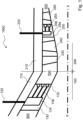
- Fig. 1 shows a partial schematic longitudinal-section view of an embodiment of a turbomachine, namely a compressor 1000.
- Compressor 1000 is divided into a bellmouth section 100 and a compression section 200.
- Section 100 is enclosed in a bellmouth section casing 110 that is part of the stator of the compressor.
- Section 200 is enclosed in a compression section casing 210 that is part of the stator of the compressor.
- Casings 110 and 210 are joined together and may be in a single piece or in multiple pieces fixed between each other.
- a flow path 500 stretches inside compressor 1000.
- a rotation axis of the compressor 1000 is indicated as XX.
- Bellmouth section 100 includes an array of struts 130 that are parts of the stator of the compressor.
- Compression section 200 includes stator vanes and rotor blades.
- moving from the inlet to the outlet i.e. from a low-pressure side of the compressor (on the left of Fig. 1 ) to a high-pressure side of the compressor (on the right of Fig. 1 ), there is a first array of vanes 230, a first array of blades 240 (belonging to a first compression stage of the compressor), a second array of vanes 250, a second array of blades 260 (belonging to a second compression stage of the compressor).
- the vanes 230 and 250 are parts of the stator, and the blades 240 and 260 are parts of the rotor.
- Flow path 500 is partially defined by the airfoil surfaces of struts 130, vanes 230 and 250, blades 240 and 260; in other words, these aerodynamic components are placed inside flow path 500 of a working fluid of turbomachine 1000.
- compressor 1000 includes two cleaning assemblies, one in the bellmouth section 100 and one in the compression section 200. It is to be noted that according to variants of this embodiment, there may be only one cleaning assembly (for example only the one assembly in the bellmouth section 100 or only the one assembly in the compression section 200), or three cleaning assemblies (i.e. an assembly in the bellmouth section 100 and two assemblies in the compression section 200, one for each compression stage of the compressor), or even more cleaning assemblies.
- the first cleaning assembly in Fig. 1 includes a duct 134 and e.g. three nozzles 135 fluidly connected to duct 134 through e.g. three channels 136.
- Duct 134 receives a washing liquid from a pipe 120; in particular, duct 134 is completely internal to strut 130 and pipe 120 comes from outside of compressor 1000, goes through casing 110 and reaches duct 134.
- the nozzles eject the washing liquid into flow path 500. It is to be noted that according to variants of this embodiment, the number of nozzles may vary but being greater than one.
- compressor 1000 has a number of struts 130, in particular six struts.
- at least one of the struts has a duct and one or more nozzles; however, preferably, this is replicated in one or two or three or more or all the struts (as shown in Fig. 5 ).
- Washing liquid ejected from nozzles 135 is very effective in cleaning vanes 230 of turbomachine 1000 being immediately downstream of struts 130 of turbomachine 1000. Washing liquid ejected from nozzles 135 is still effective in cleaning blades 240 of turbomachine 1000 being in turn immediately downstream of vanes 230 of turbomachine 1000.
- the second cleaning assembly in Fig. 1 includes a duct 254 and e.g. two nozzles 255 fluidly connected to duct 254 through e.g. two channels 256.
- Duct 254 receives a washing liquid from a pipe 220; in particular, duct 254 is completely internal to vane 250 and pipe 220 comes from outside of compressor 1000, goes through casing 210 and reaches duct 254. The nozzles eject the washing liquid into flow path 500. It is to be noted that according to variants of this embodiment, the number of nozzles may vary but being greater than one.
- compressor 1000 has a number of vanes 250.
- at least one of the vanes 250 has a duct and one or more nozzles; however, preferably, this is replicated in one or more or all the vanes.
- Washing liquid ejected from nozzles 255 is very effective in cleaning blades 260 of turbomachine 1000 being immediately downstream of vanes 250 of turbomachine 1000.
- stator aerodynamic component comprising a cleaning assembly may be a bellmouth strut (for example strut 130) or an inlet guide vane (for example vane 230) or intermediate guide vane (for example vane 250).
- a stator aerodynamic component for example strut 130
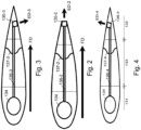
- strut 130 may be divided into a leading edge region 131, a trailing edge region 132 and an intermediate region 133.
- nozzles 135-2, 135-3, 135-4 of the component are located in trailing edge region 132 so to be in a favorable position for effective ejecting washing liquid; however, nozzles 135-2, 135-3, 135-4 are arranged differently as explained later.
- the duct 134 of the component is located in leading edge region 131 where there is big space for housing even a big strut; it is to be noted that the position of duct 134 in these three figures is the same but it may be different according to other embodiments.
- nozzle 135-2 (receiving washing fluid from a channel 136-2) arranged to eject washing liquid in an ejection direction ED-2 corresponding to a flow direction FD of flow path 500; regarding the angle, you may consider a tolerance of +/-5°.
- the nozzle is on the tip of trailing edge region 132.
- nozzle 135-3 (receiving washing fluid from a channel 136-3) arranged to eject washing liquid in an ejection direction ED-3 inclined with respect to a flow direction FD of flow path 500, the inclination being between -5° and -90°; regarding the angle, you may consider a tolerance of +/-5°.
- the nozzle is on a first lateral surface of trailing edge region 132.
- nozzle 135-4 (receiving washing fluid from a channel 136-4) arranged to eject washing liquid in an ejection direction ED-4 inclined with respect to a flow direction FD of flow path 500, the inclination being between +5° and +90°; regarding the angle, you may consider a tolerance of +/-5°.
- the nozzle is on a second lateral surface of trailing edge region 132.
- a nozzle may be designed to eject liquid in different directions, i.e. its ejection looks like a wide cone; alternatively, a cone-shaped ejection from a component may derive from the combination of the ejections from a set of nozzles mounted to the component.
- nozzles of the same component may be arranged to eject liquid in different directions.
- the upper (first radial position) nozzle of strut 130 may eject in a first direction
- the middle nozzle (second radial position) of strut 130 may eject in a second direction
- the lower nozzle (third radial position) of strut 130 may eject in a third direction.
- the component has a removable part 137-2, 137-3, 137-4, and the nozzles 135-2, 135-3, 135-4 are located in the removable part 137-2, 137-3, 137-4.
- the nozzles of the cleaning assembly and/or the duct of the cleaning assembly may be located in the removable part.
- the removal part may be useful in order to facilitate repairing compressor 1000.
- the removal part may be useful in order to facilitate customizing compressor 1000 to the requirement of e.g. a customer; in fact, for example, the body of strut 130 in these figures remain the same and, based on a request or a requirement, it is possible to easily mount part 137-2 or part 137-3 or part 137-4 to the body.
- Fig. 5 shows a possible positioning of multiple nozzles at the struts 130 of compressor 1000 of Fig. 1 not encompassed by the wording of the claims.
- nozzles located on the tips of the trailing edge regions of the struts.
- nozzles 137 located on an inner wall delimiting flow path 500 at bellmouth section 100.
- nozzles 138 located on an outer wall delimiting flow path 500 at bellmouth section 100.
- nozzles may be located on an inner and/or an outer wall delimiting flow path 500 at positions different from bellmouth. In this case, they may be located between a first stage (for example blades 240) of compressor 1000 and a last stage (for example blades 260) of compressor 1000, for example close to vanes (for example vanes 250).
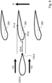
- a stationary vane 250 namely 250-6 and 250-7 and 250-8 not according to the claimed invention, are shown and their effect on rotary blades 260 of a compression stage of compressor 1000 - arrow R shows the rotation direction of blades 260.
- a nozzle 135-6 is located on the tip of the trailing edge and ejects washing liquid in an ejection direction ED-6 corresponding to flow direction FD of flow path 500.
- ED-6 ejection direction
- a nozzle 135-7 is located on the tip of the trailing edge and ejects washing liquid in an ejection direction ED-7 inclined with respect to flow direction FD of flow path 500 by an angle A-7 of approximately e.g. -15°.
- a nozzle 135-8 is located on the tip of the trailing edge and ejects washing liquid in an ejection direction ED-8 inclined with respect to flow direction FD of flow path 500 by an angle A-8 of approximately e.g. +15°.
- Nozzles 135-6, 135-7, 135-8 eject washing liquid so to reach blades 260; in particular, ejection form one nozzle reach only one blade at a time (or a limited number of vane at a time, for example two or three or four).
- nozzles 135-6, 135-7, 135-8 eject washing liquid so to reach both the pressure side and the suction side of blades 260; in Fig. 6 , portion from V to P1-6 of suction side is reached by washing liquid and portion from V to P2-6 of pressure side is reached by washing liquid, in Fig. 7 , portion from V to P1-7 (i.e.
- the quantity of washing liquid reaching the pressure side may be equal to or different from the quantity of washing liquid reaching the suction side.
- the cleaning methods disclosed herein provide that blades and/or vanes of a turbomachine are washed by ejecting a washing liquid from at least one stator aerodynamic component placed inside a flow path of a working fluid of the turbomachine; in particular, the washing liquid is ejected from one or more nozzles at least one stator aerodynamic component.
- the blades may be blades of a first stage of the turbomachine and/or blades of an intermediate stage of the turbomachine and/or blades of a last stage of the turbomachine.
- the vanes may be vanes of a first vanes array of the turbomachine and/or vanes of an intermediate vanes array of the turbomachine and/or vanes of a last vanes array of the turbomachine.
- the stator aerodynamic components as disclosed herein may be used to eject a washing liquid being for example water, in particular demineralized water, and possibly a detergent.
- the composition of the washing liquid may depend on when (for example in operating mode or in non-operating mode) and/or where cleaning is carried out.
- the stator aerodynamic components as disclosed herein may be used to eject other liquids useful for specific applications in a turbomachine.
- the cleaning method as disclosed herein may be carried out online and/or offline.
- the nozzles in the stator aerodynamic components may be activated when the turbomachine is operative, when the turbomachine is non-operative (but rotating) and both in operating mode and in non-operating mode.
- the washing liquid may be ejected for example in continuous manner or in pulsating manner.
- At least one parameter may be set or controlled when the blades and/or the vanes are washed.
- Such parameter may be for example temperature of the washing liquid, pressure of the washing liquid, composition of the washing liquid, ejection velocity of the washing liquid, ejection direction of the washing liquid.
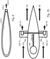
- Fig. 9 and Fig. 10 show a stator aerodynamic component, in particular a strut, of the turbomachine of Fig. 1 wherein the fluid connection between nozzle and duct is according to extreme cases.
- a duct 134-9 is directly fluidly connected to a nozzle 135-9 that ejects washing liquid in direction ED-9; in other words, the connection channel has length equal to zero (i.e. no connection channel); the duct has roughly the same cross-section area as the stator aerodynamic component.
- a duct 134 is fluidly connected to at least two nozzles 135-10 that eject washing liquid in direction ED-10 through a long channel 136-10 that, in particular, is branched (a first branch goes to a first nozzle 135-10 and a second branch goes to a second nozzle 135-10); nozzles 135-10 are located respectively on poles 139 that may project from the airfoil surface of the stator aerodynamic component (a first branch is internal to a first pole and a second branch is internal to a second pole) and that may have an aerodynamic cross-section for example smaller than the cross-section of the component (as e.g. in Fig. 10 ).
- the poles 139 may be movable (for example, they can rotate and/or translate) so that they may be located internally to the stator aerodynamic component when not used for ejecting the liquid. Such movement may be advantageously caused by a pressure of the liquid to be ejected; for example, when the pressure increases a pole moves, by effect of the pressure, out of the component and the liquid is ejected and when the pressure decreases a pole moves back, by effect of the pressure, into the component and the liquid is no longer ejected.
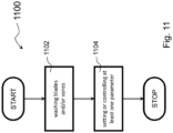
- Fig. 11 shows a flow chart 1100 of a cleaning method.
- This cleaning method comprises the steps of:- step 1102: washing blades and/or vanes of a turbomachine by ejecting a washing liquid from at least one stator aerodynamic component placed inside a flow path of a working fluid of the turbomachine, and
- the at least one parameter is selected from the group comprising temperature of the washing liquid, pressure of the washing liquid, composition of the washing liquid, ejection velocity of the washing liquid, ejection direction of the washing liquid. It is to be noted that these two steps can be performed in any suitable order and/or repeated one or more times, although in Fig. 11 there is only one step 1102 and only one step 1104. and step 1102 precedes step 1104.
- stator aerodynamic component is a component that is already a part of an existing turbomachine.
- a turbomachine may comprise stator aerodynamic components specifically designed and mounted inside its flow path for washing purposes.
- the (longitudinal and/or transversal) size of one or more components may be small and/or the shape of one or more components may such as to provide low pressure drop and/or the position and/or orientation of one or more components may be such as to provide good washing.
Landscapes
- Engineering & Computer Science (AREA)
- Mechanical Engineering (AREA)
- General Engineering & Computer Science (AREA)
- Structures Of Non-Positive Displacement Pumps (AREA)
- Nozzles (AREA)
- Cleaning By Liquid Or Steam (AREA)
- Manufacture Of Motors, Generators (AREA)
Description
- The invention relates to stator aerodynamic components with nozzles for cleaning a turbomachine, and also turbomachines comprising one or more such components.
- Turbomachines, for example rotary compressors and rotary turbines, are machines designed to process a working fluid that flows inside a flow path during operation of the machine. A turbine transfers energy from the working fluid to a rotor of the machine. A compressor transfers energy from a rotor of the machine to the working fluid. The flow path is defined partially by surfaces of a rotor of the machine and partially by surfaces of a stator of the machine.
- During operation, a turbomachine, in particular the surfaces delimiting its flow path, gets dirty; this is particularly true for turbomachines used in the "Oil & Gas" industry. Dirt may derive from the composition of the working fluid and/or from substances or droplets or particles carried by the working fluid. Dirt may stick even firmly to the surfaces delimiting the flow path; typical surfaces that get dirty are the airfoil surfaces of (rotary) blades and (stationary) vanes of a turbomachine.
-
DE 10 2015 006080 A1 discloses a compressor comprising a guide vane having a washing system.US 2014/144151 A1 discloses an engine compressor wash system.EP 1 388 656 A2 discloses a steam turbine with an extraneous matter removing system. A solution for cleaning a gas turbine compressor is known from US patent application published as "US 2007/0028947 A1 ". According toDE 10 2015 006080 - A washing assembly located at the bellmouth of the compressor upstream of its struts is easy to be installed as the bellmouth is quite big and is easily accessible being at the inlet of the machine.
- However, a washing assembly located at the bellmouth of the compressor upstream of its struts is fully effective only in cleaning the struts.
- Accordingly, it would be desirable to have a cleaning system and method effective in cleaning (stationary) vanes and/or (rotary) blades of a turbomachine, preferably also (stationary) vanes and/or (rotary) blades far from the inlet of the turbomachine.
- The present invention is defined in the accompanying claims.
- According to an aspect, the subject-matter disclosed herein relates to a stator aerodynamic component to be placed inside a flow path of a working fluid of a turbomachine; the component comprises: a duct arranged to receive a washing liquid from a pipe, and one or more nozzles fluidly connected to said duct and arranged to eject liquid into the flow path; the one or more nozzles are located internally to poles projecting from airfoil surfaces of the stator aerodynamic component.
- The stator aerodynamic components as disclosed herein are used to eject a washing liquid being for example water, in particular demineralized water, and possibly a detergent.
- A more complete appreciation of the disclosed embodiments of the invention and many of the attendant advantages thereof will be readily obtained as the same becomes better understood by reference to the following detailed description when considered in connection with the accompanying drawings, wherein:
-
Fig. 1 illustrates a partial schematic longitudinal-section view of an embodiment of a turbomachine, namely a compressor; -
Fig. 2 illustrates a schematic cross-section view of a first embodiment of a strut of the turbomachine ofFig. 1 outside the subject-matter of the claims; -
Fig. 3 illustrates a schematic cross-section view of a second embodiment of a strut of the turbomachine ofFig. 1 outside the subject-matter of the claims; -
Fig. 4 illustrates a schematic cross-section view of a third embodiment of a strut of the turbomachine ofFig. 1 outside the subject-matter of the claims; -
Fig. 5 illustrates a schematic front section view of an embodiment of the struts of the turbomachine ofFig. 1 outside the subject-matter of the claims; -
Fig. 6 illustrates a schematic cross-section view of a first embodiment of a (stationary) vane and of an embodiment of a set of (rotary) blades of the turbomachine ofFig. 1 outside the subject-matter of the claims; -
Fig. 7 illustrates a schematic cross-section view of a second embodiment of a (stationary) vane and of an embodiment of a set of (rotary) blades of the turbomachine ofFig. 1 outside the subject-matter of the claims; -
Fig. 8 illustrates a schematic cross-section view of a third embodiment of a (stationary) vane and of an embodiment of a set of (rotary) blades of the turbomachine ofFig. 1 outside the subject-matter of the claims; -
Fig. 9 illustrates a schematic cross-section view of a fourth embodiment of a strut of the turbomachine ofFig. 1 outside the subject-matter of the claims; -
Fig. 10 illustrates a schematic cross-section view of an embodiment of the turbomachine ofFig. 1 according to the invention; and -
Fig. 11 shows a flow chart of an embodiment of a cleaning method outside the subject-matter of the claims. - In order to clean a dirty surface, a washing liquid, for example water, may be sprayed onto the surface from one or more nozzles. Cleaning is very effective if the nozzle is very close to the surface to be cleaned. Dirt deposits on blades disturb aerodynamic flow around them leading to loss of entire turbine efficiency; furthermore, uneven dirt deposits on blades may cause vibrations; thus effective washing of blades is advantageous.
- In a turbomachine, a strut or a (stationary) vane is positioned near an array of (rotary) blades that are immediately downstream of the strut or vane. During rotation of the rotor, the distance between a blade of the array and the strut or vane first decreases, reaches a minimum and then increases. To be more precise, during rotation of the rotor, the distance between a leading edge region of the blade of the array and a trailing edge region of the strut or vane first decreases, reaches a minimum and then increases.
- As disclosed herein, it has been discovered that a specially configured stator aerodynamic component, for example a strut or a (stationary) vane, equipped with at least one nozzle, may advantageously be used for ejecting a washing liquid from the at least one nozzle that washes (rotary) blades and/or (stationary) vanes downstream, preferably immediately downstream, of the strut or vane. Nozzles for ejecting the washing liquid may advantageously be located at the trailing edge region of the stator aerodynamic component.
- As the strut or vane is stationary, the washing liquid may be easily fed to the strut or vane in a continuous manner through e.g. a pipe from a supply system that may be external to the turbomachine.
- Use of embodiments of the new stator aerodynamic component is contrary traditional approaches for washing turbomachines, which wash from the exterior of the turbomachine. Advantageously, embodiments of the new stator aerodynamic component and turbomachine "interior" washing method may be used for any (rotary) blades and/or (stationary) vanes even if they are far from the inlet and outlet of the turbomachine, because the cleaning system (e.g., at least a stator aerodynamic component equipped with at least one wash nozzle) is integrated into what are considered to be normal components of the turbomachine, and/or fits within the interior dimensions / spatial volume of the turbomachine to clean from the inside (or interior) of the turbomachine.
- Referring now to the drawings,
Fig. 1 shows a partial schematic longitudinal-section view of an embodiment of a turbomachine, namely acompressor 1000. -
Compressor 1000 is divided into abellmouth section 100 and acompression section 200.Section 100 is enclosed in abellmouth section casing 110 that is part of the stator of the compressor.Section 200 is enclosed in acompression section casing 210 that is part of the stator of the compressor.Casings flow path 500 stretches insidecompressor 1000. A rotation axis of thecompressor 1000 is indicated as XX. - Bellmouth
section 100 includes an array ofstruts 130 that are parts of the stator of the compressor. -
Compression section 200 includes stator vanes and rotor blades. In particular, moving from the inlet to the outlet, i.e. from a low-pressure side of the compressor (on the left ofFig. 1 ) to a high-pressure side of the compressor (on the right ofFig. 1 ), there is a first array ofvanes 230, a first array of blades 240 (belonging to a first compression stage of the compressor), a second array ofvanes 250, a second array of blades 260 (belonging to a second compression stage of the compressor). Thevanes blades -
Flow path 500 is partially defined by the airfoil surfaces ofstruts 130,vanes blades flow path 500 of a working fluid ofturbomachine 1000. - According to the embodiment of
Fig. 1 ,compressor 1000 includes two cleaning assemblies, one in thebellmouth section 100 and one in thecompression section 200. It is to be noted that according to variants of this embodiment, there may be only one cleaning assembly (for example only the one assembly in thebellmouth section 100 or only the one assembly in the compression section 200), or three cleaning assemblies (i.e. an assembly in thebellmouth section 100 and two assemblies in thecompression section 200, one for each compression stage of the compressor), or even more cleaning assemblies. - The first cleaning assembly in
Fig. 1 includes aduct 134 and e.g. threenozzles 135 fluidly connected toduct 134 through e.g. threechannels 136. Duct 134 receives a washing liquid from apipe 120; in particular,duct 134 is completely internal tostrut 130 andpipe 120 comes from outside ofcompressor 1000, goes throughcasing 110 and reachesduct 134. The nozzles eject the washing liquid intoflow path 500. It is to be noted that according to variants of this embodiment, the number of nozzles may vary but being greater than one. - As can be appreciated from e.g.
Fig. 5 ,compressor 1000 has a number ofstruts 130, in particular six struts. In the embodiment ofFig. 1 , at least one of the struts has a duct and one or more nozzles; however, preferably, this is replicated in one or two or three or more or all the struts (as shown inFig. 5 ). - Washing liquid ejected from
nozzles 135 is very effective in cleaningvanes 230 ofturbomachine 1000 being immediately downstream ofstruts 130 ofturbomachine 1000. Washing liquid ejected fromnozzles 135 is still effective in cleaningblades 240 ofturbomachine 1000 being in turn immediately downstream ofvanes 230 ofturbomachine 1000. - The second cleaning assembly in
Fig. 1 includes aduct 254 and e.g. twonozzles 255 fluidly connected toduct 254 through e.g. twochannels 256.Duct 254 receives a washing liquid from apipe 220; in particular,duct 254 is completely internal to vane 250 andpipe 220 comes from outside ofcompressor 1000, goes throughcasing 210 and reachesduct 254. The nozzles eject the washing liquid intoflow path 500. It is to be noted that according to variants of this embodiment, the number of nozzles may vary but being greater than one. - As can be appreciated,
compressor 1000 has a number ofvanes 250. In the embodiment ofFig. 1 , at least one of thevanes 250 has a duct and one or more nozzles; however, preferably, this is replicated in one or more or all the vanes. - Washing liquid ejected from
nozzles 255 is very effective in cleaningblades 260 ofturbomachine 1000 being immediately downstream ofvanes 250 ofturbomachine 1000. - From the above, it is apparent that the stator aerodynamic component comprising a cleaning assembly may be a bellmouth strut (for example strut 130) or an inlet guide vane (for example vane 230) or intermediate guide vane (for example vane 250).
- Referring to
Fig. 2 and Fig. 3 and Fig. 4 , a stator aerodynamic component, forexample strut 130, may be divided into aleading edge region 131, a trailingedge region 132 and anintermediate region 133. According to these embodiments, nozzles 135-2, 135-3, 135-4 of the component are located in trailingedge region 132 so to be in a favorable position for effective ejecting washing liquid; however, nozzles 135-2, 135-3, 135-4 are arranged differently as explained later. According to these embodiments outside the subject-matter of the claims, theduct 134 of the component is located in leadingedge region 131 where there is big space for housing even a big strut; it is to be noted that the position ofduct 134 in these three figures is the same but it may be different according to other embodiments. - Referring to
Fig. 2 , there is at least one nozzle 135-2 (receiving washing fluid from a channel 136-2) arranged to eject washing liquid in an ejection direction ED-2 corresponding to a flow direction FD offlow path 500; regarding the angle, you may consider a tolerance of +/-5°. In this case, the nozzle is on the tip of trailingedge region 132. - Referring to
Fig. 3 , there is at least one nozzle 135-3 (receiving washing fluid from a channel 136-3) arranged to eject washing liquid in an ejection direction ED-3 inclined with respect to a flow direction FD offlow path 500, the inclination being between -5° and -90°; regarding the angle, you may consider a tolerance of +/-5°. In this case, the nozzle is on a first lateral surface of trailingedge region 132. - Referring to
Fig. 4 , there is at least one nozzle 135-4 (receiving washing fluid from a channel 136-4) arranged to eject washing liquid in an ejection direction ED-4 inclined with respect to a flow direction FD offlow path 500, the inclination being between +5° and +90°; regarding the angle, you may consider a tolerance of +/-5°. In this case, the nozzle is on a second lateral surface of trailingedge region 132. - It is to be noted that a nozzle may be designed to eject liquid in different directions, i.e. its ejection looks like a wide cone; alternatively, a cone-shaped ejection from a component may derive from the combination of the ejections from a set of nozzles mounted to the component.
- It is further to be noted that nozzles of the same component may be arranged to eject liquid in different directions. For example, with reference to
Fig. 1 , the upper (first radial position) nozzle ofstrut 130 may eject in a first direction, the middle nozzle (second radial position) ofstrut 130 may eject in a second direction, the lower nozzle (third radial position) ofstrut 130 may eject in a third direction. - Referring to
Fig. 2 and Fig. 3 and Fig. 4 concerning embodiments not according to the claimed invention, the component has a removable part 137-2, 137-3, 137-4, and the nozzles 135-2, 135-3, 135-4 are located in the removable part 137-2, 137-3, 137-4. In general, in embodiments different from these figures, the nozzles of the cleaning assembly and/or the duct of the cleaning assembly may be located in the removable part. The removal part may be useful in order to facilitate repairingcompressor 1000. The removal part may be useful in order to facilitatecustomizing compressor 1000 to the requirement of e.g. a customer; in fact, for example, the body ofstrut 130 in these figures remain the same and, based on a request or a requirement, it is possible to easily mount part 137-2 or part 137-3 or part 137-4 to the body. -
Fig. 5 shows a possible positioning of multiple nozzles at thestruts 130 ofcompressor 1000 ofFig. 1 not encompassed by the wording of the claims. There are nozzles located on the tips of the trailing edge regions of the struts. There are alsonozzles 137 located on an inner wall delimitingflow path 500 atbellmouth section 100. There are alsonozzles 138 located on an outer wall delimitingflow path 500 atbellmouth section 100. These three positioning may be combined in any possible way independently from the specific combination shown inFig. 5 . - It is to be noted that, even if this is not shown in any figure, nozzles may be located on an inner and/or an outer wall delimiting
flow path 500 at positions different from bellmouth. In this case, they may be located between a first stage (for example blades 240) ofcompressor 1000 and a last stage (for example blades 260) ofcompressor 1000, for example close to vanes (for example vanes 250). - Referring to
Fig. 6 andFig. 7 andFig. 8 , three embodiments of astationary vane 250, namely 250-6 and 250-7 and 250-8 not according to the claimed invention, are shown and their effect onrotary blades 260 of a compression stage of compressor 1000 - arrow R shows the rotation direction ofblades 260. In the embodiment ofFig. 6 , a nozzle 135-6 is located on the tip of the trailing edge and ejects washing liquid in an ejection direction ED-6 corresponding to flow direction FD offlow path 500. In the embodiment ofFig. 7 , a nozzle 135-7 is located on the tip of the trailing edge and ejects washing liquid in an ejection direction ED-7 inclined with respect to flow direction FD offlow path 500 by an angle A-7 of approximately e.g. -15°. In the embodiment ofFig. 8 , a nozzle 135-8 is located on the tip of the trailing edge and ejects washing liquid in an ejection direction ED-8 inclined with respect to flow direction FD offlow path 500 by an angle A-8 of approximately e.g. +15°. - Nozzles 135-6, 135-7, 135-8 eject washing liquid so to reach
blades 260; in particular, ejection form one nozzle reach only one blade at a time (or a limited number of vane at a time, for example two or three or four). According to these embodiments, nozzles 135-6, 135-7, 135-8 eject washing liquid so to reach both the pressure side and the suction side ofblades 260; inFig. 6 , portion from V to P1-6 of suction side is reached by washing liquid and portion from V to P2-6 of pressure side is reached by washing liquid, inFig. 7 , portion from V to P1-7 (i.e. all) of suction side is reached by washing liquid and (small) portion from V to P2-7 of pressure side is reached by washing liquid; inFig. 8 , (small) portion from V to P1-8 of suction side is reached by washing liquid and portion from V to P2-8 (all) of pressure side is reached by washing liquid. In general, the quantity of washing liquid reaching the pressure side may be equal to or different from the quantity of washing liquid reaching the suction side. - As it is apparent from the above description, the cleaning methods disclosed herein provide that blades and/or vanes of a turbomachine are washed by ejecting a washing liquid from at least one stator aerodynamic component placed inside a flow path of a working fluid of the turbomachine; in particular, the washing liquid is ejected from one or more nozzles at least one stator aerodynamic component. The blades may be blades of a first stage of the turbomachine and/or blades of an intermediate stage of the turbomachine and/or blades of a last stage of the turbomachine. The vanes may be vanes of a first vanes array of the turbomachine and/or vanes of an intermediate vanes array of the turbomachine and/or vanes of a last vanes array of the turbomachine.
- The stator aerodynamic components as disclosed herein may be used to eject a washing liquid being for example water, in particular demineralized water, and possibly a detergent. The composition of the washing liquid may depend on when (for example in operating mode or in non-operating mode) and/or where cleaning is carried out. However, the stator aerodynamic components as disclosed herein may be used to eject other liquids useful for specific applications in a turbomachine.
- The cleaning method as disclosed herein may be carried out online and/or offline. In other words, the nozzles in the stator aerodynamic components may be activated when the turbomachine is operative, when the turbomachine is non-operative (but rotating) and both in operating mode and in non-operating mode.
- The washing liquid may be ejected for example in continuous manner or in pulsating manner.
- During cleaning as disclosed herein, at least one parameter may be set or controlled when the blades and/or the vanes are washed. Such parameter may be for example temperature of the washing liquid, pressure of the washing liquid, composition of the washing liquid, ejection velocity of the washing liquid, ejection direction of the washing liquid.
-
Fig. 9 and Fig. 10 show a stator aerodynamic component, in particular a strut, of the turbomachine ofFig. 1 wherein the fluid connection between nozzle and duct is according to extreme cases. - In
Fig. 9 , a duct 134-9 is directly fluidly connected to a nozzle 135-9 that ejects washing liquid in direction ED-9; in other words, the connection channel has length equal to zero (i.e. no connection channel); the duct has roughly the same cross-section area as the stator aerodynamic component. - In
Fig. 10 , according to the claimed invention aduct 134 is fluidly connected to at least two nozzles 135-10 that eject washing liquid in direction ED-10 through a long channel 136-10 that, in particular, is branched (a first branch goes to a first nozzle 135-10 and a second branch goes to a second nozzle 135-10); nozzles 135-10 are located respectively onpoles 139 that may project from the airfoil surface of the stator aerodynamic component (a first branch is internal to a first pole and a second branch is internal to a second pole) and that may have an aerodynamic cross-section for example smaller than the cross-section of the component (as e.g. inFig. 10 ). Thepoles 139 may be movable (for example, they can rotate and/or translate) so that they may be located internally to the stator aerodynamic component when not used for ejecting the liquid. Such movement may be advantageously caused by a pressure of the liquid to be ejected; for example, when the pressure increases a pole moves, by effect of the pressure, out of the component and the liquid is ejected and when the pressure decreases a pole moves back, by effect of the pressure, into the component and the liquid is no longer ejected. -
Fig. 11 shows aflow chart 1100 of a cleaning method. This cleaning method comprises the steps of:- step 1102: washing blades and/or vanes of a turbomachine by ejecting a washing liquid from at least one stator aerodynamic component placed inside a flow path of a working fluid of the turbomachine, and - step 1104: setting or controlling at least one parameter when the blades and/or the vanes are washed.
- The at least one parameter is selected from the group comprising temperature of the washing liquid, pressure of the washing liquid, composition of the washing liquid, ejection velocity of the washing liquid, ejection direction of the washing liquid. It is to be noted that these two steps can be performed in any suitable order and/or repeated one or more times, although in
Fig. 11 there is only onestep 1102 and only onestep 1104. andstep 1102 precedesstep 1104. - It is to be noted that according to the embodiments just described and shown, the stator aerodynamic component is a component that is already a part of an existing turbomachine. However, according to other embodiments, a turbomachine may comprise stator aerodynamic components specifically designed and mounted inside its flow path for washing purposes. In this case, the (longitudinal and/or transversal) size of one or more components may be small and/or the shape of one or more components may such as to provide low pressure drop and/or the position and/or orientation of one or more components may be such as to provide good washing.
Claims (9)
- A stator aerodynamic component to be placed inside a flow path (500) of a working fluid of a turbomachine (1000), the component (130, 250) comprising:- a duct (134, 254) arranged to receive a washing liquid from a pipe (120, 220),
and- one or more nozzles (135, 255) fluidly connected (136, 256) to said duct (134, 254) and arranged to eject liquid into said flow path (500);characterized in that said one or more nozzles (135-10) are located internally to poles (139) projecting from airfoil surfaces of the stator aerodynamic component. - The stator aerodynamic component of claim 1, wherein at least one first nozzle (135-10) is located internally to a first pole (139) projecting from a first airfoil surfaces of the stator aerodynamic component, and at least one second nozzle (135-10) is located internally to a second pole (139) projecting from a second airfoil surfaces of the stator aerodynamic component, the at least one first nozzle and the at least one second nozzle being fluidly connected to said duct (134).
- The stator aerodynamic component of claim 1, wherein said poles (139) have an aerodynamic cross-section being preferably smaller than the cross-section of said component (130).
- The stator aerodynamic component of claim 1, wherein said poles (139) are movable so that they may be located internally to the stator aerodynamic component when not used for ejecting said liquid.
- The stator aerodynamic component of claim 1, wherein said poles (139) are movable by effect of a pressure of said liquid.
- A turbomachine (1000), comprising at least one component (130) according to any of claims from 1 to 5.
- The turbomachine (1000) of claim 6, comprising a plurality of components (130) according to any of claims from 1 to 5.
- The turbomachine (1000) of claim 6 or 7, comprising further at least one nozzle (137, 138), said nozzle being arranged to eject liquid into a flow path (500) of a working fluid and being located on a wall delimiting said flow path (500) at a bellmouth (100) of the turbomachine (1000).
- The turbomachine of claim 6, 7 or 8, comprising further at least one nozzle, said nozzle being arranged to eject liquid into a flow path (500) of a working and being located on a wall delimiting said flow path (500) between a first stage (240) and a last stage (260) of the turbomachine (1000).
Applications Claiming Priority (2)
| Application Number | Priority Date | Filing Date | Title |
|---|---|---|---|
| IT102018000021067A IT201800021067A1 (en) | 2018-12-27 | 2018-12-27 | STATOR AERODYNAMIC COMPONENTS WITH NOZZLES AND METHODS FOR CLEANING A TURBOMACHINE |
| PCT/EP2019/025489 WO2020135931A1 (en) | 2018-12-27 | 2019-12-26 | Stator aerodynamic components with nozzles and methods for cleaning a turbomachine |
Publications (3)
| Publication Number | Publication Date |
|---|---|
| EP3902984A1 EP3902984A1 (en) | 2021-11-03 |
| EP3902984B1 true EP3902984B1 (en) | 2024-12-11 |
| EP3902984B8 EP3902984B8 (en) | 2025-02-19 |
Family
ID=65861655
Family Applications (1)
| Application Number | Title | Priority Date | Filing Date |
|---|---|---|---|
| EP19832554.0A Active EP3902984B8 (en) | 2018-12-27 | 2019-12-26 | Stator aerodynamic components with nozzles and methods for cleaning a turbomachine |
Country Status (8)
| Country | Link |
|---|---|
| US (1) | US12152498B2 (en) |
| EP (1) | EP3902984B8 (en) |
| JP (1) | JP7177275B2 (en) |
| KR (1) | KR102579575B1 (en) |
| CN (1) | CN113272523B (en) |
| AU (1) | AU2019416664B2 (en) |
| IT (1) | IT201800021067A1 (en) |
| WO (1) | WO2020135931A1 (en) |
Families Citing this family (1)
| Publication number | Priority date | Publication date | Assignee | Title |
|---|---|---|---|---|
| IT201800021067A1 (en) | 2018-12-27 | 2020-06-27 | Nuovo Pignone Tecnologie Srl | STATOR AERODYNAMIC COMPONENTS WITH NOZZLES AND METHODS FOR CLEANING A TURBOMACHINE |
Family Cites Families (16)
| Publication number | Priority date | Publication date | Assignee | Title |
|---|---|---|---|---|
| JPS56165800A (en) * | 1980-05-23 | 1981-12-19 | Hitachi Ltd | Remover of deposit from blade surface in turbo machine |
| JPH0238040B2 (en) * | 1983-06-29 | 1990-08-28 | Matsushita Electric Ind Co Ltd | SOJUSHINSOCHI |
| JPS63212798A (en) * | 1987-02-27 | 1988-09-05 | Hitachi Ltd | Axial fan dust removal device |
| JPH0610897A (en) * | 1992-06-24 | 1994-01-21 | Mitsubishi Heavy Ind Ltd | Axial flow ventilator |
| JP2002130197A (en) * | 2000-10-25 | 2002-05-09 | Mitsubishi Heavy Ind Ltd | Turbomachinery washer |
| JP3716236B2 (en) * | 2002-08-09 | 2005-11-16 | 三菱重工業株式会社 | Turbine deposit removal equipment |
| US20070028947A1 (en) * | 2005-08-04 | 2007-02-08 | General Electric Company | Gas turbine on-line compressor water wash system |
| US9016293B2 (en) | 2009-08-21 | 2015-04-28 | Gas Turbine Efficiency Sweden Ab | Staged compressor water wash system |
| EP2562430A1 (en) * | 2011-08-24 | 2013-02-27 | Siemens Aktiengesellschaft | Method for washing an axial compressor |
| US20140144151A1 (en) * | 2012-11-29 | 2014-05-29 | United Technologies Corporation | Engine Compressor Wash System |
| EP2985480A1 (en) | 2014-08-01 | 2016-02-17 | Aktiebolaget SKF | Hub bearing unit, in particular for agricultural machinery and mounting device |
| JP2016061261A (en) * | 2014-09-19 | 2016-04-25 | 三菱重工業株式会社 | Centrifugal compressor |
| JP2016196839A (en) * | 2015-04-02 | 2016-11-24 | 三菱日立パワーシステムズ株式会社 | Cleaning device for turbo type fluid machine |
| DE102015006080A1 (en) * | 2015-05-09 | 2016-11-10 | Man Diesel & Turbo Se | compressor |
| US20170204739A1 (en) | 2016-01-20 | 2017-07-20 | General Electric Company | System and Method for Cleaning a Gas Turbine Engine and Related Wash Stand |
| IT201800021067A1 (en) | 2018-12-27 | 2020-06-27 | Nuovo Pignone Tecnologie Srl | STATOR AERODYNAMIC COMPONENTS WITH NOZZLES AND METHODS FOR CLEANING A TURBOMACHINE |
-
2018
- 2018-12-27 IT IT102018000021067A patent/IT201800021067A1/en unknown
-
2019
- 2019-12-26 EP EP19832554.0A patent/EP3902984B8/en active Active
- 2019-12-26 WO PCT/EP2019/025489 patent/WO2020135931A1/en not_active Ceased
- 2019-12-26 AU AU2019416664A patent/AU2019416664B2/en active Active
- 2019-12-26 CN CN201980086691.2A patent/CN113272523B/en active Active
- 2019-12-26 US US17/309,881 patent/US12152498B2/en active Active
- 2019-12-26 KR KR1020217023248A patent/KR102579575B1/en active Active
- 2019-12-26 JP JP2021536378A patent/JP7177275B2/en active Active
Also Published As
| Publication number | Publication date |
|---|---|
| US12152498B2 (en) | 2024-11-26 |
| CN113272523A (en) | 2021-08-17 |
| WO2020135931A1 (en) | 2020-07-02 |
| EP3902984A1 (en) | 2021-11-03 |
| CA3125035A1 (en) | 2020-07-02 |
| AU2019416664B2 (en) | 2022-11-24 |
| CN113272523B (en) | 2024-02-27 |
| EP3902984B8 (en) | 2025-02-19 |
| US20220065128A1 (en) | 2022-03-03 |
| BR112021012611A2 (en) | 2021-09-08 |
| JP7177275B2 (en) | 2022-11-22 |
| JP2022514958A (en) | 2022-02-16 |
| KR20210104145A (en) | 2021-08-24 |
| KR102579575B1 (en) | 2023-09-15 |
| AU2019416664A1 (en) | 2021-07-15 |
| IT201800021067A1 (en) | 2020-06-27 |
Similar Documents
| Publication | Publication Date | Title |
|---|---|---|
| US8152934B2 (en) | Aeroengine washing system and method | |
| EP3077628B1 (en) | Methods of washing gas turbine engines and gas turbine engines | |
| EP3211186B1 (en) | System and method for cleaning a gas turbine engine and related wash stand | |
| US20140144151A1 (en) | Engine Compressor Wash System | |
| CA2759719C (en) | Engine case with wash system | |
| US6394108B1 (en) | Inside out gas turbine cleaning method | |
| MXPA06009305A (en) | Method and apparatus for cleaning a turbofan gas turbine engine. | |
| WO2005028119A1 (en) | Nozzle and method for washing gas turbine compressors | |
| JP3716236B2 (en) | Turbine deposit removal equipment | |
| AU2019416664B2 (en) | Stator aerodynamic components with nozzles and methods for cleaning a turbomachine | |
| CA3125035C (en) | Stator aerodynamic components with nozzles and methods for cleaning a turbomachine | |
| EP3077629B1 (en) | Washing nozzles and gas turbine engines | |
| JP2011021543A (en) | Steam turbine having function of washing rotor blade mounting part | |
| RU2774255C1 (en) | Aerodynamic components of the stator with nozzles and methods for cleaning the turbomachine | |
| KR101576132B1 (en) | Blade cleaning apparatus for turbine | |
| BR112021012611B1 (en) | AERODYNAMIC COMPONENT OF STATOR AND TURBOMACHINE | |
| WO2018064793A1 (en) | Collection system for a gas turbine engine wash assembly | |
| RU2331487C2 (en) | Method of and device for turbo-fan gas turbine engine cleaning | |
| JP2002130197A (en) | Turbomachinery washer |
Legal Events
| Date | Code | Title | Description |
|---|---|---|---|
| STAA | Information on the status of an ep patent application or granted ep patent |
Free format text: STATUS: UNKNOWN |
|
| STAA | Information on the status of an ep patent application or granted ep patent |
Free format text: STATUS: THE INTERNATIONAL PUBLICATION HAS BEEN MADE |
|
| PUAI | Public reference made under article 153(3) epc to a published international application that has entered the european phase |
Free format text: ORIGINAL CODE: 0009012 |
|
| STAA | Information on the status of an ep patent application or granted ep patent |
Free format text: STATUS: REQUEST FOR EXAMINATION WAS MADE |
|
| 17P | Request for examination filed |
Effective date: 20210714 |
|
| AK | Designated contracting states |
Kind code of ref document: A1 Designated state(s): AL AT BE BG CH CY CZ DE DK EE ES FI FR GB GR HR HU IE IS IT LI LT LU LV MC MK MT NL NO PL PT RO RS SE SI SK SM TR |
|
| DAV | Request for validation of the european patent (deleted) | ||
| DAX | Request for extension of the european patent (deleted) | ||
| RAP3 | Party data changed (applicant data changed or rights of an application transferred) |
Owner name: NUOVO PIGNONE TECNOLOGIE S.R.L. |
|
| P01 | Opt-out of the competence of the unified patent court (upc) registered |
Effective date: 20230526 |
|
| STAA | Information on the status of an ep patent application or granted ep patent |
Free format text: STATUS: EXAMINATION IS IN PROGRESS |
|
| 17Q | First examination report despatched |
Effective date: 20230802 |
|
| GRAP | Despatch of communication of intention to grant a patent |
Free format text: ORIGINAL CODE: EPIDOSNIGR1 |
|
| STAA | Information on the status of an ep patent application or granted ep patent |
Free format text: STATUS: GRANT OF PATENT IS INTENDED |
|
| INTG | Intention to grant announced |
Effective date: 20240927 |
|
| GRAS | Grant fee paid |
Free format text: ORIGINAL CODE: EPIDOSNIGR3 |
|
| GRAA | (expected) grant |
Free format text: ORIGINAL CODE: 0009210 |
|
| STAA | Information on the status of an ep patent application or granted ep patent |
Free format text: STATUS: THE PATENT HAS BEEN GRANTED |
|
| AK | Designated contracting states |
Kind code of ref document: B1 Designated state(s): AL AT BE BG CH CY CZ DE DK EE ES FI FR GB GR HR HU IE IS IT LI LT LU LV MC MK MT NL NO PL PT RO RS SE SI SK SM TR |
|
| RAP3 | Party data changed (applicant data changed or rights of an application transferred) |
Owner name: NUOVO PIGNONE TECHNOLOGIE - S.R.L. |
|
| REG | Reference to a national code |
Ref country code: GB Ref legal event code: FG4D |
|
| REG | Reference to a national code |
Ref country code: CH Ref legal event code: EP |
|
| REG | Reference to a national code |
Ref country code: DE Ref legal event code: R096 Ref document number: 602019063467 Country of ref document: DE |
|
| REG | Reference to a national code |
Ref country code: IE Ref legal event code: FG4D |
|
| REG | Reference to a national code |
Ref country code: DE Ref legal event code: R081 Ref document number: 602019063467 Country of ref document: DE Owner name: NUOVO PIGNONE TECNOLOGIE - S.R.L., IT Free format text: FORMER OWNER: NUOVO PIGNONE TECHNOLOGIE S.R.L., FLORENCE, IT Ref country code: DE Ref legal event code: R081 Ref document number: 602019063467 Country of ref document: DE Owner name: NUOVO PIGNONE TECHNOLOGIE - S.R.L., IT Free format text: FORMER OWNER: NUOVO PIGNONE TECHNOLOGIE S.R.L., FLORENCE, IT Ref country code: DE Ref legal event code: R081 Ref document number: 602019063467 Country of ref document: DE Owner name: NUOVO PIGNONE TECHNOLOGIE-S.R.L., IT Free format text: FORMER OWNER: NUOVO PIGNONE TECHNOLOGIE S.R.L., FLORENCE, IT |
|
| REG | Reference to a national code |
Ref country code: CH Ref legal event code: PK Free format text: BERICHTIGUNGEN Ref country code: CH Ref legal event code: PK Free format text: BERICHTIGUNG B8 |
|
| REG | Reference to a national code |
Ref country code: SE Ref legal event code: TRGR |
|
| RAP4 | Party data changed (patent owner data changed or rights of a patent transferred) |
Owner name: NUOVO PIGNONE TECNOLOGIE - S.R.L. |
|
| REG | Reference to a national code |
Ref country code: DE Ref legal event code: R081 Ref document number: 602019063467 Country of ref document: DE Owner name: NUOVO PIGNONE TECNOLOGIE - S.R.L., IT Free format text: FORMER OWNER: NUOVO PIGNONE TECHNOLOGIE - S.R.L., FLORENCE, IT |
|
| REG | Reference to a national code |
Ref country code: LT Ref legal event code: MG9D |
|
| PG25 | Lapsed in a contracting state [announced via postgrant information from national office to epo] |
Ref country code: HR Free format text: LAPSE BECAUSE OF FAILURE TO SUBMIT A TRANSLATION OF THE DESCRIPTION OR TO PAY THE FEE WITHIN THE PRESCRIBED TIME-LIMIT Effective date: 20241211 |
|
| PG25 | Lapsed in a contracting state [announced via postgrant information from national office to epo] |
Ref country code: FI Free format text: LAPSE BECAUSE OF FAILURE TO SUBMIT A TRANSLATION OF THE DESCRIPTION OR TO PAY THE FEE WITHIN THE PRESCRIBED TIME-LIMIT Effective date: 20241211 |
|
| PG25 | Lapsed in a contracting state [announced via postgrant information from national office to epo] |
Ref country code: BG Free format text: LAPSE BECAUSE OF FAILURE TO SUBMIT A TRANSLATION OF THE DESCRIPTION OR TO PAY THE FEE WITHIN THE PRESCRIBED TIME-LIMIT Effective date: 20241211 |
|
| REG | Reference to a national code |
Ref country code: NL Ref legal event code: MP Effective date: 20241211 |
|
| PG25 | Lapsed in a contracting state [announced via postgrant information from national office to epo] |
Ref country code: ES Free format text: LAPSE BECAUSE OF FAILURE TO SUBMIT A TRANSLATION OF THE DESCRIPTION OR TO PAY THE FEE WITHIN THE PRESCRIBED TIME-LIMIT Effective date: 20241211 |
|
| PG25 | Lapsed in a contracting state [announced via postgrant information from national office to epo] |
Ref country code: LV Free format text: LAPSE BECAUSE OF FAILURE TO SUBMIT A TRANSLATION OF THE DESCRIPTION OR TO PAY THE FEE WITHIN THE PRESCRIBED TIME-LIMIT Effective date: 20241211 Ref country code: GR Free format text: LAPSE BECAUSE OF FAILURE TO SUBMIT A TRANSLATION OF THE DESCRIPTION OR TO PAY THE FEE WITHIN THE PRESCRIBED TIME-LIMIT Effective date: 20250312 |
|
| PG25 | Lapsed in a contracting state [announced via postgrant information from national office to epo] |
Ref country code: RS Free format text: LAPSE BECAUSE OF FAILURE TO SUBMIT A TRANSLATION OF THE DESCRIPTION OR TO PAY THE FEE WITHIN THE PRESCRIBED TIME-LIMIT Effective date: 20250311 |
|
| PG25 | Lapsed in a contracting state [announced via postgrant information from national office to epo] |
Ref country code: NL Free format text: LAPSE BECAUSE OF FAILURE TO SUBMIT A TRANSLATION OF THE DESCRIPTION OR TO PAY THE FEE WITHIN THE PRESCRIBED TIME-LIMIT Effective date: 20241211 |
|
| REG | Reference to a national code |
Ref country code: AT Ref legal event code: MK05 Ref document number: 1750523 Country of ref document: AT Kind code of ref document: T Effective date: 20241211 |
|
| PG25 | Lapsed in a contracting state [announced via postgrant information from national office to epo] |
Ref country code: SM Free format text: LAPSE BECAUSE OF FAILURE TO SUBMIT A TRANSLATION OF THE DESCRIPTION OR TO PAY THE FEE WITHIN THE PRESCRIBED TIME-LIMIT Effective date: 20241211 |
|
| PG25 | Lapsed in a contracting state [announced via postgrant information from national office to epo] |
Ref country code: PL Free format text: LAPSE BECAUSE OF FAILURE TO SUBMIT A TRANSLATION OF THE DESCRIPTION OR TO PAY THE FEE WITHIN THE PRESCRIBED TIME-LIMIT Effective date: 20241211 |
|
| PG25 | Lapsed in a contracting state [announced via postgrant information from national office to epo] |
Ref country code: IS Free format text: LAPSE BECAUSE OF FAILURE TO SUBMIT A TRANSLATION OF THE DESCRIPTION OR TO PAY THE FEE WITHIN THE PRESCRIBED TIME-LIMIT Effective date: 20250411 |
|
| PG25 | Lapsed in a contracting state [announced via postgrant information from national office to epo] |
Ref country code: PT Free format text: LAPSE BECAUSE OF FAILURE TO SUBMIT A TRANSLATION OF THE DESCRIPTION OR TO PAY THE FEE WITHIN THE PRESCRIBED TIME-LIMIT Effective date: 20250411 |
|
| PG25 | Lapsed in a contracting state [announced via postgrant information from national office to epo] |
Ref country code: RO Free format text: LAPSE BECAUSE OF FAILURE TO SUBMIT A TRANSLATION OF THE DESCRIPTION OR TO PAY THE FEE WITHIN THE PRESCRIBED TIME-LIMIT Effective date: 20241211 Ref country code: AT Free format text: LAPSE BECAUSE OF FAILURE TO SUBMIT A TRANSLATION OF THE DESCRIPTION OR TO PAY THE FEE WITHIN THE PRESCRIBED TIME-LIMIT Effective date: 20241211 |
|
| PG25 | Lapsed in a contracting state [announced via postgrant information from national office to epo] |
Ref country code: SK Free format text: LAPSE BECAUSE OF FAILURE TO SUBMIT A TRANSLATION OF THE DESCRIPTION OR TO PAY THE FEE WITHIN THE PRESCRIBED TIME-LIMIT Effective date: 20241211 |
|
| PG25 | Lapsed in a contracting state [announced via postgrant information from national office to epo] |
Ref country code: CZ Free format text: LAPSE BECAUSE OF FAILURE TO SUBMIT A TRANSLATION OF THE DESCRIPTION OR TO PAY THE FEE WITHIN THE PRESCRIBED TIME-LIMIT Effective date: 20241211 |
|
| PG25 | Lapsed in a contracting state [announced via postgrant information from national office to epo] |
Ref country code: IT Free format text: LAPSE BECAUSE OF FAILURE TO SUBMIT A TRANSLATION OF THE DESCRIPTION OR TO PAY THE FEE WITHIN THE PRESCRIBED TIME-LIMIT Effective date: 20241211 |
|
| PG25 | Lapsed in a contracting state [announced via postgrant information from national office to epo] |
Ref country code: LU Free format text: LAPSE BECAUSE OF NON-PAYMENT OF DUE FEES Effective date: 20241226 |
|
| REG | Reference to a national code |
Ref country code: DE Ref legal event code: R097 Ref document number: 602019063467 Country of ref document: DE |
|
| PG25 | Lapsed in a contracting state [announced via postgrant information from national office to epo] |
Ref country code: MC Free format text: LAPSE BECAUSE OF FAILURE TO SUBMIT A TRANSLATION OF THE DESCRIPTION OR TO PAY THE FEE WITHIN THE PRESCRIBED TIME-LIMIT Effective date: 20241211 |
|
| REG | Reference to a national code |
Ref country code: BE Ref legal event code: MM Effective date: 20241231 |
|
| PG25 | Lapsed in a contracting state [announced via postgrant information from national office to epo] |
Ref country code: DK Free format text: LAPSE BECAUSE OF FAILURE TO SUBMIT A TRANSLATION OF THE DESCRIPTION OR TO PAY THE FEE WITHIN THE PRESCRIBED TIME-LIMIT Effective date: 20241211 |
|
| PG25 | Lapsed in a contracting state [announced via postgrant information from national office to epo] |
Ref country code: BE Free format text: LAPSE BECAUSE OF NON-PAYMENT OF DUE FEES Effective date: 20241231 |
|
| PLBE | No opposition filed within time limit |
Free format text: ORIGINAL CODE: 0009261 |
|
| STAA | Information on the status of an ep patent application or granted ep patent |
Free format text: STATUS: NO OPPOSITION FILED WITHIN TIME LIMIT |
|
| PG25 | Lapsed in a contracting state [announced via postgrant information from national office to epo] |
Ref country code: IE Free format text: LAPSE BECAUSE OF NON-PAYMENT OF DUE FEES Effective date: 20241226 |
|
| REG | Reference to a national code |
Ref country code: CH Ref legal event code: L10 Free format text: ST27 STATUS EVENT CODE: U-0-0-L10-L00 (AS PROVIDED BY THE NATIONAL OFFICE) Effective date: 20251022 |
|
| 26N | No opposition filed |
Effective date: 20250912 |
|
| REG | Reference to a national code |
Ref country code: CH Ref legal event code: U11 Free format text: ST27 STATUS EVENT CODE: U-0-0-U10-U11 (AS PROVIDED BY THE NATIONAL OFFICE) Effective date: 20260101 |
|
| PGFP | Annual fee paid to national office [announced via postgrant information from national office to epo] |
Ref country code: DE Payment date: 20251126 Year of fee payment: 7 |
|
| PGFP | Annual fee paid to national office [announced via postgrant information from national office to epo] |
Ref country code: GB Payment date: 20251119 Year of fee payment: 7 |
|
| PGFP | Annual fee paid to national office [announced via postgrant information from national office to epo] |
Ref country code: NO Payment date: 20251121 Year of fee payment: 7 |
|
| PG25 | Lapsed in a contracting state [announced via postgrant information from national office to epo] |
Ref country code: FR Free format text: LAPSE BECAUSE OF NON-PAYMENT OF DUE FEES Effective date: 20250211 |
|
| PGFP | Annual fee paid to national office [announced via postgrant information from national office to epo] |
Ref country code: SE Payment date: 20251119 Year of fee payment: 7 |
|
| PGFP | Annual fee paid to national office [announced via postgrant information from national office to epo] |
Ref country code: CH Payment date: 20260101 Year of fee payment: 7 |
|
| PG25 | Lapsed in a contracting state [announced via postgrant information from national office to epo] |
Ref country code: CY Free format text: LAPSE BECAUSE OF FAILURE TO SUBMIT A TRANSLATION OF THE DESCRIPTION OR TO PAY THE FEE WITHIN THE PRESCRIBED TIME-LIMIT Effective date: 20241211 |