EP3902207B1 - Paketweiterleitungsverfahren und netzwerkvorrichtung - Google Patents
Paketweiterleitungsverfahren und netzwerkvorrichtung Download PDFInfo
- Publication number
- EP3902207B1 EP3902207B1 EP21169051.6A EP21169051A EP3902207B1 EP 3902207 B1 EP3902207 B1 EP 3902207B1 EP 21169051 A EP21169051 A EP 21169051A EP 3902207 B1 EP3902207 B1 EP 3902207B1
- Authority
- EP
- European Patent Office
- Prior art keywords
- packet
- network device
- network
- local
- route
- Prior art date
- Legal status (The legal status is an assumption and is not a legal conclusion. Google has not performed a legal analysis and makes no representation as to the accuracy of the status listed.)
- Active
Links
Images


Classifications
-
- H—ELECTRICITY
- H04—ELECTRIC COMMUNICATION TECHNIQUE
- H04L—TRANSMISSION OF DIGITAL INFORMATION, e.g. TELEGRAPHIC COMMUNICATION
- H04L12/00—Data switching networks
- H04L12/28—Data switching networks characterised by path configuration, e.g. LAN [Local Area Networks] or WAN [Wide Area Networks]
- H04L12/46—Interconnection of networks
- H04L12/4633—Interconnection of networks using encapsulation techniques, e.g. tunneling
-
- H—ELECTRICITY
- H04—ELECTRIC COMMUNICATION TECHNIQUE
- H04L—TRANSMISSION OF DIGITAL INFORMATION, e.g. TELEGRAPHIC COMMUNICATION
- H04L12/00—Data switching networks
- H04L12/28—Data switching networks characterised by path configuration, e.g. LAN [Local Area Networks] or WAN [Wide Area Networks]
- H04L12/46—Interconnection of networks
- H04L12/4641—Virtual LANs, VLANs, e.g. virtual private networks [VPN]
- H04L12/4675—Dynamic sharing of VLAN information amongst network nodes
-
- H—ELECTRICITY
- H04—ELECTRIC COMMUNICATION TECHNIQUE
- H04L—TRANSMISSION OF DIGITAL INFORMATION, e.g. TELEGRAPHIC COMMUNICATION
- H04L45/00—Routing or path finding of packets in data switching networks
- H04L45/18—Loop-free operations
-
- H—ELECTRICITY
- H04—ELECTRIC COMMUNICATION TECHNIQUE
- H04L—TRANSMISSION OF DIGITAL INFORMATION, e.g. TELEGRAPHIC COMMUNICATION
- H04L45/00—Routing or path finding of packets in data switching networks
- H04L45/54—Organization of routing tables
-
- H—ELECTRICITY
- H04—ELECTRIC COMMUNICATION TECHNIQUE
- H04L—TRANSMISSION OF DIGITAL INFORMATION, e.g. TELEGRAPHIC COMMUNICATION
- H04L45/00—Routing or path finding of packets in data switching networks
- H04L45/58—Association of routers
- H04L45/586—Association of routers of virtual routers
-
- H—ELECTRICITY
- H04—ELECTRIC COMMUNICATION TECHNIQUE
- H04L—TRANSMISSION OF DIGITAL INFORMATION, e.g. TELEGRAPHIC COMMUNICATION
- H04L45/00—Routing or path finding of packets in data switching networks
- H04L45/64—Routing or path finding of packets in data switching networks using an overlay routing layer
-
- H—ELECTRICITY
- H04—ELECTRIC COMMUNICATION TECHNIQUE
- H04L—TRANSMISSION OF DIGITAL INFORMATION, e.g. TELEGRAPHIC COMMUNICATION
- H04L45/00—Routing or path finding of packets in data switching networks
- H04L45/66—Layer 2 routing, e.g. in Ethernet based MAN's
-
- H—ELECTRICITY
- H04—ELECTRIC COMMUNICATION TECHNIQUE
- H04L—TRANSMISSION OF DIGITAL INFORMATION, e.g. TELEGRAPHIC COMMUNICATION
- H04L63/00—Network architectures or network communication protocols for network security
- H04L63/02—Network architectures or network communication protocols for network security for separating internal from external traffic, e.g. firewalls
- H04L63/0272—Virtual private networks
-
- H—ELECTRICITY
- H04—ELECTRIC COMMUNICATION TECHNIQUE
- H04L—TRANSMISSION OF DIGITAL INFORMATION, e.g. TELEGRAPHIC COMMUNICATION
- H04L69/00—Network arrangements, protocols or services independent of the application payload and not provided for in the other groups of this subclass
- H04L69/22—Parsing or analysis of headers
-
- H—ELECTRICITY
- H04—ELECTRIC COMMUNICATION TECHNIQUE
- H04L—TRANSMISSION OF DIGITAL INFORMATION, e.g. TELEGRAPHIC COMMUNICATION
- H04L12/00—Data switching networks
- H04L12/28—Data switching networks characterised by path configuration, e.g. LAN [Local Area Networks] or WAN [Wide Area Networks]
- H04L12/46—Interconnection of networks
- H04L12/4604—LAN interconnection over a backbone network, e.g. Internet, Frame Relay
- H04L2012/4629—LAN interconnection over a backbone network, e.g. Internet, Frame Relay using multilayer switching, e.g. layer 3 switching
-
- H—ELECTRICITY
- H04—ELECTRIC COMMUNICATION TECHNIQUE
- H04L—TRANSMISSION OF DIGITAL INFORMATION, e.g. TELEGRAPHIC COMMUNICATION
- H04L45/00—Routing or path finding of packets in data switching networks
- H04L45/50—Routing or path finding of packets in data switching networks using label swapping, e.g. multi-protocol label switch [MPLS]
- H04L45/507—Label distribution
-
- H—ELECTRICITY
- H04—ELECTRIC COMMUNICATION TECHNIQUE
- H04L—TRANSMISSION OF DIGITAL INFORMATION, e.g. TELEGRAPHIC COMMUNICATION
- H04L45/00—Routing or path finding of packets in data switching networks
- H04L45/74—Address processing for routing
- H04L45/745—Address table lookup; Address filtering
Definitions
- This application relates to the field of communications technologies, and in particular, to a packet forwarding method and a network device.
- VXLAN Virtual extensible Local Area Network
- a VXLAN of the data center usually includes a core device, a plurality of peer VXLAN tunnel endpoint (VXLAN Tunnel end point, VTEP) devices, and virtual machines (virtual machine, VM) separately connected to the VTEP devices.
- the VM may be deployed on a server connected to the VTEP device.
- a virtual network function (virtual network function, VNF) network element may be distributed on a plurality of VMs, and the plurality of VMs can implement a same network function and share a same service internet (Internet Protocol, IP) address.
- IP Internet Protocol
- the document EP 3 270 546 A1 shows a message processing method, device and system, especially using a virtual routing forwarding table.
- the document WO 2016/077060 A1 shows an optimized inter-VRF route leaking in network overlay based environments.
- the document US 2017/339054 A1 shows forwarding tables for virtual networking devices, and according methods and systems.
- the document US 2010/027549 A1 shows a method and apparatus for providing virtual private network identifiers in communications networks.
- Embodiments of this application provide a packet forwarding method and a network device.
- the network device receives a packet from a transmission tunnel (namely, a packet forwarded by another tunnel endpoint device)
- the network device forwards the packet based on a virtual routing and forwarding (Virtual Routing Forwarding, VRF) table including only a route whose next hop is a local outbound interface, to prevent the packet from being forwarded to the another tunnel endpoint device again. This avoids a routing loop and ensures normal packet forwarding.
- VRF Virtual Routing Forwarding
- the network device may selectively forward a packet based on whether the packet comes from the network side, for example, a peer tunnel endpoint device on the network side, based on the first VRF table including only the local route, or based on the second VRF table including both the remote route and the local route. Specifically, when the network device receives the packet from the transmission tunnel (namely, the packet forwarded by the another tunnel endpoint device), the network device forwards the packet based on the first VRF table including only the route whose next hop is the local outbound interface, to prevent the packet from being forwarded to the another tunnel endpoint device again. In other words, this avoids the routing loop and ensures the normal packet forwarding.
- the network device may separately implement the load balancing based on the first VRF table and the second VRF table, to ensures, to some extent, balanced resource usage of the traffic forwarding.
- Names or numbers of the steps in this application do not mean that the steps in the method procedure need to be performed in a chronological/logical order indicated by the names or numbers.
- An execution sequence of the steps in the procedure that have been named or numbered may be changed based on technical objectives to be implemented, provided that a same or similar technical effect can be achieved.
- Division into units in this application is logical division and may be other division in an actual implementation. For example, a plurality of units may be combined or integrated into another system, or some features may be ignored or not performed.
- the displayed or discussed mutual couplings or direct couplings or communications connections may be implemented through some interfaces.
- the indirect couplings or communications connections between the units may be implemented in electronic or other forms. This is not limited in this application.
- units or subunits described as separate parts may or may not be physically separate, may or may not be physical units, or may be distributed in a plurality of circuit units. Some or all of the units may be selected based on actual requirements to achieve the objectives of the solutions of this application.
- telecommunications devices each use a dedicated platform structure.
- software and hardware of different telecommunications devices are independent of each other.
- a mobility management entity mobility management entity
- MME mobility management entity
- S-GW serving gateway
- P-GW packet data network gateway
- a telecommunications network element is gradually migrating from a dedicated hardware platform to a universal hardware platform in the data center, and deployed on a VM of a server in the data center in a form of a VNF network element, to form a telecommunications cloud data center network.
- the data center network transforms from a conventional virtual local area network (virtual local area network, VLAN) to a VXLAN network and a software-defined networking (network defined software, SDN), to implement adaptation and association between the network and a service, and improve resource utilization efficiency and service provisioning efficiency.
- VLAN virtual local area network
- SDN software-defined networking
- the VXLAN is a network virtualization technology in which a data packet sent from a source host is encapsulated into a user datagram protocol (User Datagram Protocol, UDP), an IP and MAC of a physical network are used as an outer header for encapsulation, and then the data packet is transmitted over the network. After the data packet reaches a destination, a tunnel endpoint decapsulates the data packet and sends data to a target host.
- UDP User Datagram Protocol
- IP and MAC IP and MAC of a physical network
- a tunnel endpoint decapsulates the data packet and sends data to a target host.
- the VXLAN technology may be used to construct a layer 2 virtual network on an existing layer 3 network, to implement layer 2 communication between VMs.
- FIG. 1 is a schematic diagram of networking of a data center according to an embodiment of this application.
- typical VXLAN networking may include a data center gateway (data center gateway, DCGW), a spine (spine) switch, a leaf (leaf) switch, and a VM.
- the DCGW may be connected to one or more spine switches, the spine switch may be connected to one or more leaf switches, and the leaf switch may be connected to one or more VMs.
- a VXLAN tunnel may be established between the DCGW and the leaf switch, and a VXLAN tunnel may also be established between leaf switches.
- a VTEP device is a network device that can encapsulate and decapsulate a VXLAN packet.
- a source IP address of the VXLAN packet is an IP address of a source end VTEP device
- a destination IP address of the VXLAN packet is an IP address of a destination end VTEP device.
- One pair of VTEP addresses corresponds to one VXLAN tunnel.
- the source end VTEP device sends the encapsulated packet to the destination end VTEP device through a tunnel, and then the destination end VTEP device decapsulates the received encapsulated packet.
- the leaf switch device in FIG. 1 may have a capability of encapsulating and decapsulating the VXLAN packet. That is, the leaf switch device in FIG. 1 is a VTEP device.
- a network virtualization edge (Network Virtualization Edge, NVE) device is a network entity that implements a network virtualization function. After a packet is encapsulated and converted by the NVE device, a layer 2 virtual network may be established between NVE devices based on a layer 3 underly network.
- the leaf switch device in FIG. 1 is an NVE device.
- the VTEP device is a type of the NVE device.
- a layer 2 gateway (Level-2 GateWay, L2GW) is similar to a layer 2 access device of a conventional network.
- the L2GW allows a tenant to access a VXLAN virtual network and allows communication between subnets on a same VXLAN network.
- a concept of a layer 3 gateway (Level-3 Gateway, L3 GW) is introduced to perform communication between VXLAN networks and communication between the VXLAN network and a non-VXLAN network.
- the L3GW may be used for cross-subnet communication of the VXLAN network and external network access.
- the leaf switch in FIG. 1 may be used as an L2GW or an L3GW, or may be used as both an L2GW and L3 GW. In other words, the leaf switch may be the L2GW/L3GW.
- traffic of a data center network may be divided into north-south traffic and east-west traffic.
- the north-south traffic refers to traffic from an external network to the data center network and traffic from the data center network to the external network.
- the north-south traffic is transmitted in a data center, one endpoint of a VXLAN tunnel is at the DCGW, and the other endpoint is at the leaf switch.
- the traffic is transmitted from the DCGW to the leaf switch or from the leaf switch to the DCGW.
- the east-west traffic refers to traffic between VMs in the data center. When the east-west traffic is transmitted in the data center, both the endpoints of the VXLAN tunnel are at leaf switches.
- the traffic is generally transmitted from one leaf switch to the other leaf switch.
- traffic flows from the DCGW to a leaf switch or from another leaf switch to a leaf switch the traffic belongs to traffic flowing from a network side.
- traffic flows from a user-side device or a user network to a leaf switch for example, the traffic flows from a VM mounted to the leaf switch to the leaf switch, the traffic belongs to traffic flowing from a user side.
- FIG. 2a is a schematic diagram of north-south traffic according to an embodiment of this application.
- a packet entering a data center from an external network is forwarded by a DCGW to a leaf switch 1 by using a spine switch 1, and is finally forwarded by the leaf switch 1 to a VM 1 connected to the leaf switch 1.
- the VM 1 sends a packet generated by the VM 1 to the leaf switch 1, the leaf switch 1 forwards the packet to the DCGW by using the spine switch 1, and finally the DCGW sends the packet to the external network.
- Both traffic from the DCGW to the VM 1 and traffic from the VM 1 to the DCGW may be referred to as the north-south traffic.
- FIG. 2b is a schematic diagram of east-west traffic according to an embodiment of this application.
- a VM 1 sends a packet generated by the VM 1 to a leaf switch 1, the leaf switch 1 forwards the packet to a leaf switch 2 by using a spine switch 1, and finally the leaf switch 2 sends the packet to a VM 3.
- Traffic from the VM 1 to the VM 3 may be referred to as the east-west traffic.
- a leaf switch can implement shortest-path forwarding for east-west traffic between two VMs in different subnets.
- a spine switch forwards the traffic to the other nearest VM, to prevent inter-subnet traffic from being diverted to a DCGW and form a traffic bottleneck.
- FIG. 3 is a schematic diagram of a service scenario according to an embodiment of this application.
- a VNF network element is distributed on a VM 1 to a VM 4, and the VM 1 to the VM 4 may share a same IP address (the IP address may be, for example, 1.1.1.1).
- the VM 1 and the VM 2 are connected to a leaf switch 1, and the VM 3 and the VM 4 are a connected to a leaf switch 2.
- a corresponding next hop may be a local VM, or may be a remote VM.
- a route whose next hop is the local VM of the leaf switch 1 is referred to as a local route
- a route whose next hop is the remote VM is referred to as a remote route.
- the remote VM is a VM mounted to another leaf switch different from the leaf switch 1.
- a VRF table of the leaf switch 1 may be specifically:
- next-hop routes corresponding to the leaf switch 1 include two local routes (the next hops are the VM 1 and the VM 2) and two remote routes (the next hops are the VM 3 and the VM 4).
- a VRF table of the leaf switch 2 may be specifically:
- next-hop routes corresponding to the leaf switch 2 include two remote routes (the next hops are the VM 1 and the VM 2) and two local routes (the next hops are the VM 3 and the VM 4).
- a local route and a remote route are equivalent on a leaf switch.
- the leaf switch may equivalently select one of a plurality of local routes and/or remote routes corresponding to the IP address, and forward the packet based on the selected route.
- a routing loop is likely to occur.
- the leaf switch 1 receives a packet whose destination address is 1.1.1.1
- the leaf switch 1 selects the VM 3 or the VM 4 from the VM 1 to the VM 4 as a next-hop route.
- the leaf switch 1 forwards the packet to the leaf switch 2 by using the spine switch 1.
- the leaf switch 2 may select the VM 1 or the VM 2 as a next-hop route. Therefore, the leaf switch 2 forwards the packet to the leaf switch 1 by using a spine switch 2. In other words, the packet is always forwarded between the leaf switch 1 and the leaf switch 2, and cannot reach the destination address, causing the routing loop.
- FIG. 4 is a schematic diagram of another scenario according to an embodiment of this application.
- a VNF network element 1 is distributed on a VM 1 and a VM 2, and the VM 1 and the VM 2 share an IP address 1.1.1.1.
- a VNF network element 2 is distributed on a VM 3 and a VM 4, and the VM 3 and the VM 4 share an IP address 2.2.2.2.
- the VM 1 to the VM 3 are connected to a leaf switch 1, and the VM 4 is connected to a leaf switch 2.
- a VRF table of the leaf switch 1 may be specifically:
- a VRF table of the leaf switch 2 may be specifically:
- VRF tables information in the foregoing VRF tables is intended to describe the application scenario of this embodiment more clearly. It can be understood that, in an actual application, content and a style of the information presented in the VRF tables may be specifically designed as required.
- a leaf switch 1 if a leaf switch 1 preferably selects a local route when forwarding a packet, when the leaf switch 1 receives a packet sent by the VM 1 or the VM 2, and a destination address of the packet is 2.2.2.2, the leaf switch 1 always selects to forward the packet to the local VM 3 according to a rule of preferably selecting a local route.
- the VM 3 is always in a heavy-load state while the VM 4 is always in an idle state. In this way, load balancing cannot be implemented.
- the foregoing description uses a network structure shown in FIG. 1 as an example. It may be understood that a possible structure of the data center network is not limited thereto.
- the data center network may alternatively not include a spine switch, or a layer 2 leaf switch is further connected to a leaf switch, and then the layer 2 leaf switch is mounted to VM user equipment, and the like.
- the layer 2 leaf switch may also be understood as a user-side device.
- the foregoing problem may still exist.
- an embodiment of this application provides a packet forwarding method.
- a network device receives a packet from a transmission tunnel (namely, a packet forwarded by another tunnel endpoint device)
- the network device forwards the packet based on a virtual routing and forwarding (Virtual Routing Forwarding, VRF) table including only a route whose next hop is a local outbound interface, to prevent the packet from being forwarded to the another tunnel endpoint device again.
- VRF Virtual Routing Forwarding
- the packet forwarding method provided in this embodiment of this application may be applied to a network architecture in which a VXLAN tunnel is deployed and that is shown in FIG. 3 or FIG. 4 , or may be applied to a network architecture in which another transmission tunnel (for example, an MPLS tunnel or an SR tunnel) is deployed. This is not limited herein.
- FIG. 5 is a schematic flowchart of a packet forwarding method 500 according to an embodiment of this application. As shown in FIG. 5 , the packet forwarding method 500 provided in this embodiment of this application includes the following steps.
- a network device receives a first packet.
- the network device is a device connected to one or more VMs in a data center network.
- the network device may be an access switch (for example, a leaf switch) or an access router connected to a server on which the one or more VMs are deployed.
- the network device may receive a packet sent by another device, and forward the packet to a VM connected to the network device.
- the network device may alternatively receive a packet sent by a VM connected to the network device, and forward the packet to another device.
- FIG. 3 or FIG. 4 is used as an example.
- the network device may be the leaf switch 1, and the another device may be the leaf switch 2.
- the network device may be the spine switch 1, and the another device may be the spine switch 2.
- the first packet may be the packet sent by the VM connected to the network device, or may be the packet sent by the another network device, for example, a packet sent by a spine switch to the network device.
- the network device forwards the first packet based on the first VRF table.
- the first VRF table consists of one or more local routes, and next-hop outbound interfaces of the one or more local routes are all local outbound interfaces.
- the network device determines whether the first packet carries the tunnel attribute information. If the first packet carries the tunnel attribute information, it indicates that the first packet is transmitted to the network device through a tunnel on a network side. For example, the first packet is sent by a VTEP device on the network side.
- the VXLAN scenario shown in FIG. 3 is still used as an example. If the first packet carries VXLAN tunnel attribute information, the first packet may be transmitted by a DCGW to the network device through a VXLAN tunnel between the DCGW and the network device, and continues to be forwarded by the network device.
- the first packet may be a packet that needs to be sent by a VM mounted to the network device, and may be sent by the network device to a VM mounted to another device (for example, another leaf switch).
- the network device forwards the first packet based on the first VRF table, to avoid a routing loop caused when the network device selects a remote route during first packet forwarding.
- the network device includes the first VRF table and a second VRF table, in other words, the network device includes two VRF tables used to implement packet forwarding.
- the first VRF table includes the one or more local routes.
- the local route is a route that is used to reach a user-side device connected to the network device, for example, a route of a VM mounted to the leaf switch 1.
- the next-hop outbound interfaces of the one or more local routes are all the local outbound interfaces, in other words, the first VRF table includes only the local routes.
- the remote route may be a route that is in the VRF table stored in the network device and that is used to reach a user-side device mounted to the another network device, for example, a route of a VM mounted to the leaf switch 2.
- the network device forwards the first packet based on the first VRF table may include: The network device determines, based on a destination address of the first packet, a first route used to forward the first packet in the first VRF table. The first route belongs to the one or more local routes. The network device forwards the first packet based on the first route. In other words, the network device determines, based on the destination address of the first packet, one or more routes that may be used to forward the first packet in the first VRF table. Prefixes of the one or more routes match the destination address of the first packet.
- the network device may determine, according to a specific forwarding policy, for example, a load balancing policy, the first route in the one or more routes as a route used to forward the first packet, and finally forward the first packet based on the first route. For example, if the network device determines, based on the destination address of the first packet, that routes that can be used to forward the first packet include the first route, a second route, and a third route in the first VRF table, the network device may select, according to the load balancing policy, the proper first route as the route used to forward the first packet.
- a specific forwarding policy for example, a load balancing policy
- the network device may determine, based on the tunnel attribute information carried in the second packet and the destination address in the second packet, a second route used to forward the second packet in the first VRF table.
- the second route belongs to the one or more local routes.
- the network device randomly selects, according to the load balancing policy, the second route as a route used to forward the second packet.
- the network device may implement load balancing of the packet forwarding based on the first VRF table and ensure proper virtual machine resource utilization.
- the load balancing policy may be implemented based on, for example, an equal-cost multi-path (Equal-Cost Multi-Path, ECMP) routing.
- Equal-Cost Multi-Path Equal-Cost Multi-Path
- the network device when the network device receives the packet carrying the tunnel attribute information, the network device forwards the packet based on the VRF table including only the local routes, to prevent the packet from being forwarded to another tunnel endpoint device again. This avoids a routing loop, and ensures normal packet forwarding.
- the network device further includes the second VRF table. If the first packet does not carry the tunnel attribute information, the network device forwards the first packet based on the second VRF table.
- the second VRF table includes a plurality of routes, and the plurality of routes includes the one or more local routes and one or more routes whose next-hop outbound interfaces are remote outbound interfaces.
- the second VRF table may include the remote route and the local routes.
- the second VRF table may be a VRF table obtained through learning by the network device. The network device obtains the second VRF table by learning a route advertised by another device on a network and a route on a local server.
- the network device establishes a border gateway protocol peer (border gateway protocol peer, BGP Peer) relationship with a route reflector (route reflector, RR) on the network.
- Border gateway protocol peer border gateway protocol peer, BGP Peer
- route reflector route reflector
- the RR may advertise a route to a BGP peer connected to the RR, so that the network device can learn the route and generate or update the second VRF table.
- that the network device forwards the first packet based on the second VRF table may be specifically implemented by configuring a logical interface of the network device.
- the logical interface "a vbdif interface" of the network device namely, a local service port, may be configured to bind with the second VRF table.
- all packets received by the network device from the vbdif interface are forwarded based on the bound second VRF table.
- the vbdif interface is the local service port in the network device, and is mainly configured to receive a packet sent by a user-side device of the network device, for example, the VM mounted to the network device, and does not receive a packet sent by the another tunnel endpoint device. Therefore, by binding the vbdif interface with the second VRF table, a packet received locally can be normally forwarded based on the second VRF table.
- the network device may obtain the first VRF table in a plurality of manners.
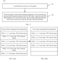
- the network device may generate the first VRF table based on the second VRF table. Specifically, the network device determines a route whose next hop is a local outbound interface in the second VRF table. In other words, the network device determines a local route in the second VRF table, and generates the first VRF table based on the route whose next hop is the local outbound interface in the second VRF table. Simply speaking, the network device may generate the first VRF table by copying the local route in the second VRF table, so that the generated first VRF table includes only the local route. For details, refer to FIG. 6a and FIG. 6b. FIG. 6a and FIG. 6b are a schematic diagram of a VRF table according to an embodiment of this application. FIG.
- FIG. 6(a) represents a second VRF table
- FIG. 6(b) represents a first VRF table generated based on the second VRF table. It can be seen from FIG. 6a and FIG. 6b that, the second VRF table includes a local route and a remote route, but the first VRF table includes only the local route. In addition, the local route included in the first VRF table is the same as the local route included in the second VRF table.
- a network device may generate the first VRF table based on a fact that an obtained route is the local route. Specifically, when the network device obtains a route, for example, when the network device receives a new route advertised by a BGP peer, the network device determines whether the obtained route is the local route. If the obtained route is the local route, the network device generates or updates the first VRF table based on the obtained local route.
- FIG. 7 is a schematic diagram of encapsulation of a VXLAN tunnel packet according to an embodiment of this application.
- an original packet includes a payload (payload), an inner internet protocol header (inner IP header), and an inner Ethernet header (inner ethernet header).
- the packet After VXALN tunnel encapsulation is performed on the packet, a VXLAN header is added to the packet, and a standard UDP header is in front of the VXLAN header. Therefore, the packet includes an outer Ethernet header (outer ethernet header), an outer internet protocol header (outer IP header), and an outer user datagram protocol header (outer UDP header).
- the VXLAN header in the packet or some data bits in the VXLAN header may be used as tunnel attribute information, to identify that the packet is from a VXLAN tunnel.
- the network device may retain some data bits in the packet, to mark a tunnel attribute of the packet and facilitate a subsequent forwarding operation performed on the packet.
- a format of the VXLAN packet refer to the standard RFC 7348. All content of the standard is introduced into the embodiments of this application herein.
- the tunnel attribute information carried in the first packet may be specifically tunnel attribute information, for example, MPLS tunnel attribute information or SR tunnel attribute information. This is not specifically limited in this embodiment of this application.
- a leaf switch 1 includes a first VRF table and a second VRF table.
- the first VRF table is specifically:
- the second VRF table further includes remote routes whose next hops are a VM 3 and a VM 4. For details, refer to the foregoing description.
- the leaf switch 1 When the leaf switch 1 includes the first VRF table and the second VRF table, after the leaf switch 1 receives a packet forwarded by a DCGW by using a spine switch 1, the leaf switch 1 may determine that the packet carries VXLAN tunnel attribute information. Therefore, the leaf switch 1 may forward the packet based on the first VRF table. For example, when a destination address of a packet is 1.1.1.1, the leaf switch 1 may determine, in the first VRF table, that a route whose next hop is the VM 1 and a route whose next hop is the VM 2 are routes that may be used to forward the packet. Then, the leaf switch 1 determines, in the foregoing two routes, one route that is used to forward the packet. In this way, the packet is forwarded to the local VM 1 or the local VM 2.
- the leaf switch 1 For a packet forwarded to the leaf switch 1 by a tunnel endpoint device, for example, the DCGW or a leaf switch 2, the leaf switch 1 implements packet forwarding based on the first VRF table, to prevent the leaf switch 1 from selecting a remote route and forwarding the packet to the leaf switch 2 again. This prevents a routing loop.
- a tunnel endpoint device for example, the DCGW or a leaf switch 2
- the leaf switch 1 when the leaf switch 1 receives a packet that does not carry the tunnel attribute information, the leaf switch 1 forwards the packet based on the second VRF table including a local route and the remote route. In other words, there is no need to preferably select the local route. Therefore, it can be ensured that the leaf switch 1 selects, according to a load balancing policy, one of the local route and the remote route as a route used to forward the packet. To be specific, it can be ensured that load balancing can be implemented when the leaf switch 1 forwards a packet (namely, a local packet) sent by a local VM, and a resource waste is avoided.
- a packet namely, a local packet
- FIG. 8 is a schematic diagram of another service scenario according to an embodiment of this application.
- a VNF network element 1 is distributed on a VM 1 and a VM 3, and the VM 1 and the VM 3 share a same IP address 1.1.1.1.
- a VNF network element 2 is distributed on a VM 2 and a VM 4, and the VM 2 and the VM 4 share a same IP address 2.2.2.2.
- the VM 1 and the VM 2 are connected to a leaf switch 1
- the VM 3 and the VM 4 are connected to a leaf switch 2.
- a first VRF table included in the leaf switch 1 is specifically:
- a second VRF table included in the leaf switch 1 is specifically:
- the leaf switch 1 When the leaf switch 1 receives a packet forwarded by a DCGW or the leaf switch 2, the leaf switch 1 forwards the packet based on the first VRF table. It is ensured that a packet whose destination address is 1.1.1.1 is forwarded to the VM 1 and a packet whose destination address is 2.2.2.2 is forwarded to the VM 2, and a case that the leaf switch 1 forwards the packet to the leaf switch 2 again does not occur.
- the leaf switch 1 forwards the packet based on the foregoing second VRF table.
- the leaf switch 1 may select, according to a load balancing policy, one route from two routes whose next hops are the VM 2 and the VM 4 as a route used to forward the packet, to implement load balancing and avoid a resource waste.
- a routing loop can be avoided.
- it can be ensured that a packet is forwarded according to the load balancing policy, and the resource waste is avoided.
- FIG. 9 is a schematic structural diagram of a network device according to an embodiment of this application.
- a network device 90 provided in this embodiment of this application may be, for example, the leaf switch 1 or the leaf switch 2 in the foregoing method embodiments.
- the network device 90 includes a first VRF table and a second VRF table.
- the network device further includes a receiving unit 901, configured to receive a first packet; and a processing unit 902, configured to: if the first packet carries tunnel attribute information, forward the first packet based on the first VRF table.
- the first VRF table consists of one or more local routes, and next-hop outbound interfaces of the one or more local routes are all local outbound interfaces.
- the processing unit 902 is further configured to: generate the first VRF table based on a fact that an obtained route is a local route; determine a route whose next hop is a local outbound interface in the second VRF table; and generate the first VRF table based on the route whose next hop is the local outbound interface in the second VRF table.
- the processing unit 902 is further configured to: if the first packet does not carry the tunnel attribute information, forward the first packet based on the second VRF table.
- the second VRF table includes a plurality of routes, and the plurality of routes includes the one or more local routes and one or more routes whose next-hop outbound interfaces are remote outbound interfaces.
- the processing unit 902 is further configured to: determine, based on a destination address of the first packet, a first route used to forward the first packet in the first VRF table, where the first route belongs to the one or more local routes; and forward the first packet based on the first route.
- the receiving unit 901 is further configured to: receive a second packet, where the second packet includes the destination address; determine, based on the tunnel attribute information carried in the second packet and the destination address in the second packet, a second route used to forward the second packet in the first VRF table, where the second route belongs to the one or more local routes; and forward the second packet based on the second route.
- the tunnel attribute information is virtual extensible local area network VXLAN tunnel attribute information, multi-protocol label switching MPLS tunnel attribute information, or segment routing SR tunnel attribute information.
- the network device is a device connected to one or more virtual machines in a data center network.
- FIG. 10 is a schematic structural diagram of a network device according to an embodiment of this application.
- a network device 100 is provided.
- the network device 100 may be, for example, the network device in the foregoing method embodiments.
- the network device 100 includes a processor 1001.
- the processor 1001 is coupled to a memory 1002.
- the memory 1002 may be independent of the processor 1001 or independent of the network device 100, for example, a memory (Memory) #3.
- the memory 1002 may alternatively be inside the processor 1001 or the network device 100 (a Memory #1 and a Memory #2).
- the memory 1002 may be a physically independent unit, or may be storage space, a network hard disk, or the like on a cloud server.
- the plurality of memories 1002 may be located at a same location or different locations, and may be used independently or in cooperation.
- the memory 1002 is configured to store a computer-readable instruction (or referred to as a computer program).
- the processor 1001 is configured to read the computer-readable instruction to implement the method provided in any one of the foregoing aspects related to the network device and the implementations thereof.
- the network device 100 further includes a transceiver 1003, configured to receive and send data.
- the processor 1001 may be a central processing unit, a general-purpose processor, a digital signal processor, an application-specific integrated circuit, a field programmable gate array or another programmable logic device, a transistor logic device, a hardware component, or any combination thereof.
- the processor may implement or execute various example logical blocks, modules, and circuits described with reference to content disclosed in this application.
- the processor may be a combination of processors implementing a computing function, for example, a combination of one or more microprocessors, or a combination of the digital signal processor and a microprocessor.
- the memory 1002 may include a volatile memory (volatile memory), for example, a random access memory (RAM).
- the memory may alternatively include a non-volatile memory (non-volatile memory), for example, a flash memory (flash memory), a hard disk drive (hard disk drive, HDD), a solid-state drive (solid-state drive, SSD), cloud storage (cloud storage), network attached storage (network attached storage), or a network drive (network drive).
- non-volatile memory for example, a flash memory (flash memory), a hard disk drive (hard disk drive, HDD), a solid-state drive (solid-state drive, SSD), cloud storage (cloud storage), network attached storage (network attached storage), or a network drive (network drive).
- flash memory flash memory
- HDD hard disk drive
- solid-state drive solid-state drive
- cloud storage cloud storage
- network attached storage network attached storage
- network drive network drive
- the disclosed system, apparatus, and method may be implemented in other manners.
- the described apparatus embodiment is merely an example.
- division into the units is merely logical function division and may be other division in an actual implementation.
- a plurality of units or components may be combined or integrated into another system, or some features may be ignored or not performed.
- the displayed or discussed mutual couplings or direct couplings or communication connections may be implemented through some interfaces.
- the indirect couplings or communication connections between the apparatuses or units may be implemented in electronic, mechanical, or other forms.
- the units described as separate parts may or may not be physically separate, and parts displayed as units may or may not be physical units, may be located in one position, or may be distributed on a plurality of network units. Some or all of the units may be selected based on actual requirements to achieve the objectives of the solutions of the embodiments.
- functional units in the embodiments of this application may be integrated into one processing unit, or each of the units may exist alone physically, or two or more units are integrated into one unit.
- the integrated unit may be implemented in a form of hardware, or may be implemented in a form of a software functional unit.
- the integrated unit When the integrated unit is implemented in the form of a software functional unit and sold or used as an independent product, the integrated unit may be stored in a computer-readable storage medium. Based on such an understanding, the technical solutions of this application essentially, or the part contributing to the prior art, or all or some of the technical solutions may be implemented in the form of a software product.
- the computer software product is stored in a storage medium and includes several instructions for instructing a computer device (which may be a personal computer, a server, or a network device) to perform all or some of the steps of the methods described in the embodiments of this application.
- the foregoing storage medium includes any medium that can store program code, for example, a USB flash drive, a read-only memory, a random access memory, a magnetic disk, or an optical disc.
Landscapes
- Engineering & Computer Science (AREA)
- Computer Networks & Wireless Communication (AREA)
- Signal Processing (AREA)
- Computer Security & Cryptography (AREA)
- Computer Hardware Design (AREA)
- Computing Systems (AREA)
- General Engineering & Computer Science (AREA)
- Data Exchanges In Wide-Area Networks (AREA)
Claims (6)
- Paketweiterleitungsverfahren, das von einem Netzgerät durchgeführt wird, wobei das Netzgerät eine erste "Virtual-Routing-Forwarding"-Tabelle, VRF-Tabelle, und eine zweite VRF-Tabelle umfasst, wobei:∘ die erste VRF-Tabelle aus einer oder mehreren lokalen Routen besteht und jede "Next-Hop"-Ausgangsschnittstelle der einen oder der mehreren lokalen Routen eine lokale Ausgangsschnittstelle des Netzgeräts ist und∘ die zweite VRF-Tabelle eine Vielzahl von Routen umfasst und die Vielzahl von Routen die eine oder die mehreren lokalen Routen und mindestens eine entfernte Route, deren "Next-Hop"-Ausgangsschnittstelle des Netzgeräts eine entfernte Ausgangsschnittstelle ist, umfasst,wobei das Verfahren die folgenden Schritte umfasst:• Empfangen (Schritt 501) eines ersten Pakets;• Bestimmen, ob das erste Paket Tunnelattributinformationen enthält, wobei die Tunnelattributinformationen angeben, dass das erste Paket durch einen netzseitigen Tunnel an das Netzgerät gesendet wird:∘ wenn das erste Paket die Tunnelattributinformationen enthält, Weiterleiten (Schritt 502) des ersten Pakets basierend auf der ersten VRF-Tabelle und,∘ wenn das erste Paket die Tunnelattributinformationen nicht enthält, Weiterleiten des ersten Pakets basierend auf der zweiten VRF-Tabelle.
- Verfahren nach Anspruch 1, wobei das Verfahren vor dem Empfangen des ersten Pakets Folgendes umfasst:
Generieren der ersten VRF-Tabelle basierend auf einer Gegebenheit, dass eine erhaltene Route eine lokale Route ist. - Verfahren nach einem der Ansprüche 1 bis 2, wobei die Tunnelattributinformationen "Virtual-Extensible-Local-Area-Network"-Tunnelattributinformationen, VXLAN-Tunnelattributinformationen, "Multi-Protocol-Label-Switching"-Tunnelattributinformationen, MPLS-Tunnelattributinformationen, oder "Segment-Routing"-Tunnelattributinformationen, SR-Tunnelattributinformationen, sind.
- Verfahren nach einem der Ansprüche 1 bis 3, wobei das Netzgerät ein mit einer Vielzahl virtueller Maschinen in einem Rechenzentrumsnetz verbundenes Gerät ist.
- Netzgerät (90), das konfiguriert ist, um alle Schritte eines der Verfahren nach den Ansprüchen 1-4 durchzuführen.
- Computerprogrammprodukt, das computerlesbare Anweisungen umfasst, die, wenn die computerlesbaren Anweisungen von einem Prozessor eines Netzgeräts ausgeführt werden, bewirken, dass das Netzgerät alle Schritte eines der Verfahren nach den Ansprüchen 1-4 durchführt.
Applications Claiming Priority (1)
| Application Number | Priority Date | Filing Date | Title |
|---|---|---|---|
| CN202010314463.0A CN113542111B (zh) | 2020-04-20 | 2020-04-20 | 一种报文转发方法及网络设备 |
Publications (2)
| Publication Number | Publication Date |
|---|---|
| EP3902207A1 EP3902207A1 (de) | 2021-10-27 |
| EP3902207B1 true EP3902207B1 (de) | 2024-11-27 |
Family
ID=75581419
Family Applications (1)
| Application Number | Title | Priority Date | Filing Date |
|---|---|---|---|
| EP21169051.6A Active EP3902207B1 (de) | 2020-04-20 | 2021-04-19 | Paketweiterleitungsverfahren und netzwerkvorrichtung |
Country Status (3)
| Country | Link |
|---|---|
| US (1) | US11706140B2 (de) |
| EP (1) | EP3902207B1 (de) |
| CN (1) | CN113542111B (de) |
Families Citing this family (5)
| Publication number | Priority date | Publication date | Assignee | Title |
|---|---|---|---|---|
| CN113660164B (zh) * | 2020-05-12 | 2024-08-23 | 华为技术有限公司 | 一种报文转发方法及网络设备 |
| US11601395B1 (en) * | 2021-12-22 | 2023-03-07 | Uab 360 It | Updating parameters in a mesh network |
| US11770362B2 (en) * | 2021-12-29 | 2023-09-26 | Uab 360 It | Access control in a mesh network |
| CN115277550B (zh) * | 2022-06-21 | 2023-11-28 | 阿里巴巴(中国)有限公司 | 虚拟网络的路由系统、路由方法及路由装置 |
| US12542738B2 (en) * | 2023-12-18 | 2026-02-03 | Cornelis Networks, Inc. | Virtual routing fields |
Family Cites Families (15)
| Publication number | Priority date | Publication date | Assignee | Title |
|---|---|---|---|---|
| US6907039B2 (en) * | 2002-07-20 | 2005-06-14 | Redback Networks Inc. | Method and apparatus for routing and forwarding between virtual routers within a single network element |
| US7792021B1 (en) * | 2005-08-22 | 2010-09-07 | Sprint Communications Company L.P. | Solutions for preventing routing loops and load balancing when connected to a multihomed autonomous system |
| US20100027549A1 (en) | 2008-07-31 | 2010-02-04 | Michael Satterlee | Method and apparatus for providing virtual private network identifier |
| US8570865B2 (en) * | 2011-02-14 | 2013-10-29 | Mellanox Technologies Ltd. | Reducing power consumption in a fat-tree network |
| US9692687B2 (en) * | 2011-03-18 | 2017-06-27 | Alcatel Lucent | Method and apparatus for rapid rerouting of LDP packets |
| CN103139068B (zh) * | 2011-11-28 | 2015-12-09 | 华为技术有限公司 | 转发报文的方法、路由器和系统 |
| US9331941B2 (en) * | 2013-08-12 | 2016-05-03 | Cisco Technology, Inc. | Traffic flow redirection between border routers using routing encapsulation |
| US9397946B1 (en) | 2013-11-05 | 2016-07-19 | Cisco Technology, Inc. | Forwarding to clusters of service nodes |
| CN103634217B (zh) * | 2013-11-13 | 2017-02-08 | 华为技术有限公司 | 路由信息发布的方法、传输报文的方法及装置 |
| US9678840B2 (en) * | 2014-04-29 | 2017-06-13 | Cisco Technology, Inc. | Fast failover for application performance based WAN path optimization with multiple border routers |
| US9634936B2 (en) * | 2014-06-30 | 2017-04-25 | Juniper Networks, Inc. | Service chaining across multiple networks |
| US10050876B2 (en) * | 2014-11-12 | 2018-08-14 | Cisco Technology, Inc. | Optimized inter-VRF (virtual routing and forwarding) route leaking in network overlay based environments |
| CN106209553B (zh) | 2015-04-30 | 2019-07-23 | 华为技术有限公司 | 报文处理方法、设备及系统 |
| CN108809847B (zh) * | 2017-05-05 | 2021-11-19 | 华为技术有限公司 | 实现负载均衡的方法、装置和网络系统 |
| CN109995654B (zh) * | 2017-12-29 | 2022-05-20 | 中兴通讯股份有限公司 | 一种基于隧道传输数据的方法及装置 |
-
2020
- 2020-04-20 CN CN202010314463.0A patent/CN113542111B/zh active Active
-
2021
- 2021-04-16 US US17/232,431 patent/US11706140B2/en active Active
- 2021-04-19 EP EP21169051.6A patent/EP3902207B1/de active Active
Also Published As
| Publication number | Publication date |
|---|---|
| US20210328922A1 (en) | 2021-10-21 |
| CN113542111B (zh) | 2024-05-14 |
| CN113542111A (zh) | 2021-10-22 |
| US11706140B2 (en) | 2023-07-18 |
| EP3902207A1 (de) | 2021-10-27 |
Similar Documents
| Publication | Publication Date | Title |
|---|---|---|
| EP3902207B1 (de) | Paketweiterleitungsverfahren und netzwerkvorrichtung | |
| US10757008B2 (en) | Flow specification protocol-based communications method, device, and system | |
| US11683272B2 (en) | Packet processing method, packet forwarding apparatus, and packet processing apparatus | |
| US20210359879A1 (en) | Packet forwarding method and network device | |
| US20220007251A1 (en) | Using location indentifier separation protocol to implement a distributed user plane function architecture for 5g mobility | |
| US10749797B2 (en) | Service label routing in a network | |
| JP7674401B2 (ja) | パケット処理方法およびネットワークデバイス | |
| US20250071054A1 (en) | Route Processing Method and Network Device | |
| EP3902211B1 (de) | Paketweiterleitungsverfahren und netzwerkvorrichtung | |
| US20220360526A1 (en) | Routing information publishing method, apparatus, and system | |
| US11929851B2 (en) | Gateway selection method, device, and system | |
| JP2024545917A (ja) | Vxlanパケット伝送方法、ネットワークデバイス、およびシステム | |
| CN117097818A (zh) | 一种报文处理的方法及相关设备 | |
| US12184545B2 (en) | Packet processing method and related apparatus |
Legal Events
| Date | Code | Title | Description |
|---|---|---|---|
| PUAI | Public reference made under article 153(3) epc to a published international application that has entered the european phase |
Free format text: ORIGINAL CODE: 0009012 |
|
| STAA | Information on the status of an ep patent application or granted ep patent |
Free format text: STATUS: REQUEST FOR EXAMINATION WAS MADE |
|
| 17P | Request for examination filed |
Effective date: 20210419 |
|
| AK | Designated contracting states |
Kind code of ref document: A1 Designated state(s): AL AT BE BG CH CY CZ DE DK EE ES FI FR GB GR HR HU IE IS IT LI LT LU LV MC MK MT NL NO PL PT RO RS SE SI SK SM TR |
|
| B565 | Issuance of search results under rule 164(2) epc |
Effective date: 20210917 |
|
| STAA | Information on the status of an ep patent application or granted ep patent |
Free format text: STATUS: EXAMINATION IS IN PROGRESS |
|
| 17Q | First examination report despatched |
Effective date: 20230310 |
|
| REG | Reference to a national code |
Free format text: PREVIOUS MAIN CLASS: H04L0012400000 Ref country code: DE Ref legal event code: R079 Ref document number: 602021022287 Country of ref document: DE Free format text: PREVIOUS MAIN CLASS: H04L0012400000 Ipc: H04L0045180000 |
|
| GRAP | Despatch of communication of intention to grant a patent |
Free format text: ORIGINAL CODE: EPIDOSNIGR1 |
|
| STAA | Information on the status of an ep patent application or granted ep patent |
Free format text: STATUS: GRANT OF PATENT IS INTENDED |
|
| INTG | Intention to grant announced |
Effective date: 20240703 |
|
| RIC1 | Information provided on ipc code assigned before grant |
Ipc: H04L 69/22 20220101ALI20240621BHEP Ipc: H04L 45/00 20220101ALI20240621BHEP Ipc: H04L 12/46 20060101ALI20240621BHEP Ipc: H04L 45/745 20220101ALI20240621BHEP Ipc: H04L 9/40 20220101ALI20240621BHEP Ipc: H04L 45/64 20220101ALI20240621BHEP Ipc: H04L 45/50 20220101ALI20240621BHEP Ipc: H04L 45/586 20220101ALI20240621BHEP Ipc: H04L 45/18 20220101AFI20240621BHEP |
|
| GRAS | Grant fee paid |
Free format text: ORIGINAL CODE: EPIDOSNIGR3 |
|
| GRAA | (expected) grant |
Free format text: ORIGINAL CODE: 0009210 |
|
| STAA | Information on the status of an ep patent application or granted ep patent |
Free format text: STATUS: THE PATENT HAS BEEN GRANTED |
|
| AK | Designated contracting states |
Kind code of ref document: B1 Designated state(s): AL AT BE BG CH CY CZ DE DK EE ES FI FR GB GR HR HU IE IS IT LI LT LU LV MC MK MT NL NO PL PT RO RS SE SI SK SM TR |
|
| REG | Reference to a national code |
Ref country code: GB Ref legal event code: FG4D |
|
| REG | Reference to a national code |
Ref country code: CH Ref legal event code: EP |
|
| REG | Reference to a national code |
Ref country code: IE Ref legal event code: FG4D |
|
| REG | Reference to a national code |
Ref country code: DE Ref legal event code: R096 Ref document number: 602021022287 Country of ref document: DE |
|
| REG | Reference to a national code |
Ref country code: LT Ref legal event code: MG9D |
|
| REG | Reference to a national code |
Ref country code: NL Ref legal event code: MP Effective date: 20241127 |
|
| PG25 | Lapsed in a contracting state [announced via postgrant information from national office to epo] |
Ref country code: IS Free format text: LAPSE BECAUSE OF FAILURE TO SUBMIT A TRANSLATION OF THE DESCRIPTION OR TO PAY THE FEE WITHIN THE PRESCRIBED TIME-LIMIT Effective date: 20250327 Ref country code: PT Free format text: LAPSE BECAUSE OF FAILURE TO SUBMIT A TRANSLATION OF THE DESCRIPTION OR TO PAY THE FEE WITHIN THE PRESCRIBED TIME-LIMIT Effective date: 20250327 Ref country code: HR Free format text: LAPSE BECAUSE OF FAILURE TO SUBMIT A TRANSLATION OF THE DESCRIPTION OR TO PAY THE FEE WITHIN THE PRESCRIBED TIME-LIMIT Effective date: 20241127 |
|
| PG25 | Lapsed in a contracting state [announced via postgrant information from national office to epo] |
Ref country code: FI Free format text: LAPSE BECAUSE OF FAILURE TO SUBMIT A TRANSLATION OF THE DESCRIPTION OR TO PAY THE FEE WITHIN THE PRESCRIBED TIME-LIMIT Effective date: 20241127 Ref country code: NL Free format text: LAPSE BECAUSE OF FAILURE TO SUBMIT A TRANSLATION OF THE DESCRIPTION OR TO PAY THE FEE WITHIN THE PRESCRIBED TIME-LIMIT Effective date: 20241127 |
|
| REG | Reference to a national code |
Ref country code: AT Ref legal event code: MK05 Ref document number: 1746824 Country of ref document: AT Kind code of ref document: T Effective date: 20241127 |
|
| PG25 | Lapsed in a contracting state [announced via postgrant information from national office to epo] |
Ref country code: BG Free format text: LAPSE BECAUSE OF FAILURE TO SUBMIT A TRANSLATION OF THE DESCRIPTION OR TO PAY THE FEE WITHIN THE PRESCRIBED TIME-LIMIT Effective date: 20241127 |
|
| PG25 | Lapsed in a contracting state [announced via postgrant information from national office to epo] |
Ref country code: ES Free format text: LAPSE BECAUSE OF FAILURE TO SUBMIT A TRANSLATION OF THE DESCRIPTION OR TO PAY THE FEE WITHIN THE PRESCRIBED TIME-LIMIT Effective date: 20241127 |
|
| PG25 | Lapsed in a contracting state [announced via postgrant information from national office to epo] |
Ref country code: NO Free format text: LAPSE BECAUSE OF FAILURE TO SUBMIT A TRANSLATION OF THE DESCRIPTION OR TO PAY THE FEE WITHIN THE PRESCRIBED TIME-LIMIT Effective date: 20250227 |
|
| PG25 | Lapsed in a contracting state [announced via postgrant information from national office to epo] |
Ref country code: LV Free format text: LAPSE BECAUSE OF FAILURE TO SUBMIT A TRANSLATION OF THE DESCRIPTION OR TO PAY THE FEE WITHIN THE PRESCRIBED TIME-LIMIT Effective date: 20241127 Ref country code: AT Free format text: LAPSE BECAUSE OF FAILURE TO SUBMIT A TRANSLATION OF THE DESCRIPTION OR TO PAY THE FEE WITHIN THE PRESCRIBED TIME-LIMIT Effective date: 20241127 Ref country code: GR Free format text: LAPSE BECAUSE OF FAILURE TO SUBMIT A TRANSLATION OF THE DESCRIPTION OR TO PAY THE FEE WITHIN THE PRESCRIBED TIME-LIMIT Effective date: 20250228 |
|
| PG25 | Lapsed in a contracting state [announced via postgrant information from national office to epo] |
Ref country code: PL Free format text: LAPSE BECAUSE OF FAILURE TO SUBMIT A TRANSLATION OF THE DESCRIPTION OR TO PAY THE FEE WITHIN THE PRESCRIBED TIME-LIMIT Effective date: 20241127 |
|
| PG25 | Lapsed in a contracting state [announced via postgrant information from national office to epo] |
Ref country code: RS Free format text: LAPSE BECAUSE OF FAILURE TO SUBMIT A TRANSLATION OF THE DESCRIPTION OR TO PAY THE FEE WITHIN THE PRESCRIBED TIME-LIMIT Effective date: 20250227 |
|
| PG25 | Lapsed in a contracting state [announced via postgrant information from national office to epo] |
Ref country code: SM Free format text: LAPSE BECAUSE OF FAILURE TO SUBMIT A TRANSLATION OF THE DESCRIPTION OR TO PAY THE FEE WITHIN THE PRESCRIBED TIME-LIMIT Effective date: 20241127 |
|
| PGFP | Annual fee paid to national office [announced via postgrant information from national office to epo] |
Ref country code: DE Payment date: 20250305 Year of fee payment: 5 |
|
| PG25 | Lapsed in a contracting state [announced via postgrant information from national office to epo] |
Ref country code: DK Free format text: LAPSE BECAUSE OF FAILURE TO SUBMIT A TRANSLATION OF THE DESCRIPTION OR TO PAY THE FEE WITHIN THE PRESCRIBED TIME-LIMIT Effective date: 20241127 |
|
| PG25 | Lapsed in a contracting state [announced via postgrant information from national office to epo] |
Ref country code: EE Free format text: LAPSE BECAUSE OF FAILURE TO SUBMIT A TRANSLATION OF THE DESCRIPTION OR TO PAY THE FEE WITHIN THE PRESCRIBED TIME-LIMIT Effective date: 20241127 |
|
| PG25 | Lapsed in a contracting state [announced via postgrant information from national office to epo] |
Ref country code: RO Free format text: LAPSE BECAUSE OF FAILURE TO SUBMIT A TRANSLATION OF THE DESCRIPTION OR TO PAY THE FEE WITHIN THE PRESCRIBED TIME-LIMIT Effective date: 20241127 |
|
| PG25 | Lapsed in a contracting state [announced via postgrant information from national office to epo] |
Ref country code: SK Free format text: LAPSE BECAUSE OF FAILURE TO SUBMIT A TRANSLATION OF THE DESCRIPTION OR TO PAY THE FEE WITHIN THE PRESCRIBED TIME-LIMIT Effective date: 20241127 |
|
| PG25 | Lapsed in a contracting state [announced via postgrant information from national office to epo] |
Ref country code: CZ Free format text: LAPSE BECAUSE OF FAILURE TO SUBMIT A TRANSLATION OF THE DESCRIPTION OR TO PAY THE FEE WITHIN THE PRESCRIBED TIME-LIMIT Effective date: 20241127 |
|
| PG25 | Lapsed in a contracting state [announced via postgrant information from national office to epo] |
Ref country code: IT Free format text: LAPSE BECAUSE OF FAILURE TO SUBMIT A TRANSLATION OF THE DESCRIPTION OR TO PAY THE FEE WITHIN THE PRESCRIBED TIME-LIMIT Effective date: 20241127 |
|
| REG | Reference to a national code |
Ref country code: DE Ref legal event code: R097 Ref document number: 602021022287 Country of ref document: DE |
|
| PG25 | Lapsed in a contracting state [announced via postgrant information from national office to epo] |
Ref country code: SE Free format text: LAPSE BECAUSE OF FAILURE TO SUBMIT A TRANSLATION OF THE DESCRIPTION OR TO PAY THE FEE WITHIN THE PRESCRIBED TIME-LIMIT Effective date: 20241127 |
|
| PLBE | No opposition filed within time limit |
Free format text: ORIGINAL CODE: 0009261 |
|
| STAA | Information on the status of an ep patent application or granted ep patent |
Free format text: STATUS: NO OPPOSITION FILED WITHIN TIME LIMIT |
|
| REG | Reference to a national code |
Ref country code: CH Ref legal event code: L10 Free format text: ST27 STATUS EVENT CODE: U-0-0-L10-L00 (AS PROVIDED BY THE NATIONAL OFFICE) Effective date: 20251008 |
|
| 26N | No opposition filed |
Effective date: 20250828 |
|
| REG | Reference to a national code |
Ref country code: CH Ref legal event code: H13 Free format text: ST27 STATUS EVENT CODE: U-0-0-H10-H13 (AS PROVIDED BY THE NATIONAL OFFICE) Effective date: 20251125 |
|
| PG25 | Lapsed in a contracting state [announced via postgrant information from national office to epo] |
Ref country code: LU Free format text: LAPSE BECAUSE OF NON-PAYMENT OF DUE FEES Effective date: 20250419 |
|
| PG25 | Lapsed in a contracting state [announced via postgrant information from national office to epo] |
Ref country code: MC Free format text: LAPSE BECAUSE OF FAILURE TO SUBMIT A TRANSLATION OF THE DESCRIPTION OR TO PAY THE FEE WITHIN THE PRESCRIBED TIME-LIMIT Effective date: 20241127 |
|
| GBPC | Gb: european patent ceased through non-payment of renewal fee |
Effective date: 20250419 |
|
| REG | Reference to a national code |
Ref country code: BE Ref legal event code: MM Effective date: 20250430 |
|
| PG25 | Lapsed in a contracting state [announced via postgrant information from national office to epo] |
Ref country code: GB Free format text: LAPSE BECAUSE OF NON-PAYMENT OF DUE FEES Effective date: 20250419 |
|
| PG25 | Lapsed in a contracting state [announced via postgrant information from national office to epo] |
Ref country code: FR Free format text: LAPSE BECAUSE OF NON-PAYMENT OF DUE FEES Effective date: 20250430 |
|
| PG25 | Lapsed in a contracting state [announced via postgrant information from national office to epo] |
Ref country code: BE Free format text: LAPSE BECAUSE OF NON-PAYMENT OF DUE FEES Effective date: 20250430 |
|
| PG25 | Lapsed in a contracting state [announced via postgrant information from national office to epo] |
Ref country code: CH Free format text: LAPSE BECAUSE OF NON-PAYMENT OF DUE FEES Effective date: 20250430 |