EP3902115A1 - Rotor, motor, and wiper motor - Google Patents
Rotor, motor, and wiper motor Download PDFInfo
- Publication number
- EP3902115A1 EP3902115A1 EP19899516.9A EP19899516A EP3902115A1 EP 3902115 A1 EP3902115 A1 EP 3902115A1 EP 19899516 A EP19899516 A EP 19899516A EP 3902115 A1 EP3902115 A1 EP 3902115A1
- Authority
- EP
- European Patent Office
- Prior art keywords
- circumferential surface
- permanent magnet
- rotor
- rotor core
- radial direction
- Prior art date
- Legal status (The legal status is an assumption and is not a legal conclusion. Google has not performed a legal analysis and makes no representation as to the accuracy of the status listed.)
- Pending
Links
Images


Classifications
-
- H—ELECTRICITY
- H02—GENERATION; CONVERSION OR DISTRIBUTION OF ELECTRIC POWER
- H02K—DYNAMO-ELECTRIC MACHINES
- H02K1/00—Details of the magnetic circuit
- H02K1/06—Details of the magnetic circuit characterised by the shape, form or construction
- H02K1/22—Rotating parts of the magnetic circuit
- H02K1/27—Rotor cores with permanent magnets
- H02K1/2706—Inner rotors
- H02K1/272—Inner rotors the magnetisation axis of the magnets being perpendicular to the rotor axis
- H02K1/274—Inner rotors the magnetisation axis of the magnets being perpendicular to the rotor axis the rotor consisting of two or more circumferentially positioned magnets
- H02K1/2753—Inner rotors the magnetisation axis of the magnets being perpendicular to the rotor axis the rotor consisting of two or more circumferentially positioned magnets the rotor consisting of magnets or groups of magnets arranged with alternating polarity
- H02K1/278—Surface mounted magnets; Inset magnets
-
- B—PERFORMING OPERATIONS; TRANSPORTING
- B60—VEHICLES IN GENERAL
- B60S—SERVICING, CLEANING, REPAIRING, SUPPORTING, LIFTING, OR MANOEUVRING OF VEHICLES, NOT OTHERWISE PROVIDED FOR
- B60S1/00—Cleaning of vehicles
- B60S1/02—Cleaning windscreens, windows or optical devices
- B60S1/04—Wipers or the like, e.g. scrapers
- B60S1/06—Wipers or the like, e.g. scrapers characterised by the drive
- B60S1/08—Wipers or the like, e.g. scrapers characterised by the drive electrically driven
-
- H—ELECTRICITY
- H02—GENERATION; CONVERSION OR DISTRIBUTION OF ELECTRIC POWER
- H02K—DYNAMO-ELECTRIC MACHINES
- H02K21/00—Synchronous motors having permanent magnets; Synchronous generators having permanent magnets
- H02K21/12—Synchronous motors having permanent magnets; Synchronous generators having permanent magnets with stationary armatures and rotating magnets
- H02K21/14—Synchronous motors having permanent magnets; Synchronous generators having permanent magnets with stationary armatures and rotating magnets with magnets rotating within the armatures
- H02K21/16—Synchronous motors having permanent magnets; Synchronous generators having permanent magnets with stationary armatures and rotating magnets with magnets rotating within the armatures having annular armature cores with salient poles
-
- H—ELECTRICITY
- H02—GENERATION; CONVERSION OR DISTRIBUTION OF ELECTRIC POWER
- H02K—DYNAMO-ELECTRIC MACHINES
- H02K7/00—Arrangements for handling mechanical energy structurally associated with dynamo-electric machines, e.g. structural association with mechanical driving motors or auxiliary dynamo-electric machines
- H02K7/10—Structural association with clutches, brakes, gears, pulleys or mechanical starters
- H02K7/116—Structural association with clutches, brakes, gears, pulleys or mechanical starters with gears
- H02K7/1163—Structural association with clutches, brakes, gears, pulleys or mechanical starters with gears where at least two gears have non-parallel axes without having orbital motion
- H02K7/1166—Structural association with clutches, brakes, gears, pulleys or mechanical starters with gears where at least two gears have non-parallel axes without having orbital motion comprising worm and worm-wheel
-
- H—ELECTRICITY
- H02—GENERATION; CONVERSION OR DISTRIBUTION OF ELECTRIC POWER
- H02K—DYNAMO-ELECTRIC MACHINES
- H02K2213/00—Specific aspects, not otherwise provided for and not covered by codes H02K2201/00 - H02K2211/00
- H02K2213/03—Machines characterised by numerical values, ranges, mathematical expressions or similar information
-
- H—ELECTRICITY
- H02—GENERATION; CONVERSION OR DISTRIBUTION OF ELECTRIC POWER
- H02K—DYNAMO-ELECTRIC MACHINES
- H02K29/00—Motors or generators having non-mechanical commutating devices, e.g. discharge tubes or semiconductor devices
- H02K29/03—Motors or generators having non-mechanical commutating devices, e.g. discharge tubes or semiconductor devices with a magnetic circuit specially adapted for avoiding torque ripples or self-starting problems
Definitions
- Patent Document 1 International Publication No. 2015/102047
- the wall thickness on the side of the inner circumferential surface of the permanent magnet can be cut correspondingly as compared with the conventional art. In other words, the radial wall thickness of the permanent magnet can be reduced. Therefore, the material cost for the permanent magnet can be reduced.
- an outer flange portion 16 projecting radially outward is formed at an opening 6a of the first motor case 6.
- an outer flange portion 17 projecting radially outward is formed at an opening 7a of the second motor case 7.
- the outer flange portions 16 and 17 are butted against each other to form the motor case 5 having an internal space. Then, in the internal space of the motor case 5, the outer circumferential surface of the stator 8 is fitted to the inner circumferential surfaces of the first motor case 6 and the second motor case 7.
- each portion of the rotor core 132 and the permanent magnet 133 in the conventional rotor 109 will be described with the same name and the same reference numeral as each portion of the rotor core 32 and the permanent magnet 33 in the rotor 9 of the present embodiment.
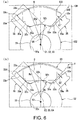
- FIG. 6 is an explanatory view of circumferential rattling of the permanent magnet, wherein (a) shows the conventional rotor 109 and (b) shows the rotor 9 of the present embodiment.
- (a) of FIG. 6 corresponds to (a) of FIG. 5 described above.
- (b) of FIG. 6 corresponds to (b) of FIG. 5 described above.
- (a) of FIG. 7 is an enlarged view of the portion B of (a) of FIG. 6 .
- (b) of FIG. 7 is an enlarged view of the portion C of (b) of FIG. 6 . Under the above configuration, as shown in (a) and (b) of FIG.
- a gap S3 remains between the radially inner side of the salient pole side surface 35a and the radially inner side of the magnet side surface 33a in a state where the magnet side surface 33a is brought into contact with the salient pole side surface 35a.
- the deceleration part 3 includes the gear case 40 to which the motor case 5 is attached, and a worm deceleration mechanism 41 housed in the gear case 40.
- the gear case 40 is made of a material having excellent heat dissipation such as aluminum die cast.
- the gear case 40 is formed in a box shape having an opening 40a on one surface, and has a gear housing portion 42 housing the worm deceleration mechanism 41 inside. Further, on a side wall 40b of the gear case 40, an opening 43 for communicating the through hole 10a of the first motor case 6 and the gear housing portion 42 is formed at a portion where the first motor case 6 is integrally molded.
- the worm wheel 45 meshed with the worm shaft 44 is provided with an output shaft 48 at the radial center of the worm wheel 45.
- the output shaft 48 is arranged coaxially with the direction of the rotation shaft of the worm wheel 45.
- the output shaft 48 protrudes through the bearing boss 49 of the gear case 40 to the outside of the gear case 40.
- a spline 48a that can be connected to an electrical component (not shown) is formed at the protruding tip of the output shaft 48.
- the cover 63 that covers the controller board 62 configured in this way is made of resin. Further, the cover 63 is formed to bulge slightly outward. Then, the inner surface side of the cover 63 is a controller housing portion 56 for housing the controller board 62 or the like. Further, the connector (not shown) is integrally molded on the outer circumferential portion of the cover 63. This connector is formed to be fitted with a connector extending from an external power source (not shown). Then, the controller board 62 is electrically connected to the terminal of the connector (not shown). As a result, the electric power of the external power source is supplied to the controller board 62.
- the external device controls the switching timing of a switching element or the like of the power module (not shown) based on the rotation position detection signal of the worm wheel 45, and controls the drive of the motor part 2.
- the output of the drive signal of the power module and the drive control of the motor part 2 may be executed by the controller part 4 instead of the external device (not shown).
- the angle ⁇ 1 formed by the salient pole side surfaces 35a facing each other of the circumferentially adjacent salient poles 35 and the angle ⁇ 2 formed by the magnet side surfaces 33a on both sides of the permanent magnet 33 in the circumferential direction are set to satisfy the above formula (2).
- the distance Lt between the outer circumferential surface 32b of the rotor core 32 and the radially outermost end of the salient pole 35 and the distance Lme between the inner circumferential surface 33b of the permanent magnet 33 and the radially outermost end of the magnet side surface 33a are set to satisfy the above formula (3).
Landscapes
- Engineering & Computer Science (AREA)
- Power Engineering (AREA)
- Mechanical Engineering (AREA)
- Permanent Field Magnets Of Synchronous Machinery (AREA)
- Iron Core Of Rotating Electric Machines (AREA)
- Connection Of Motors, Electrical Generators, Mechanical Devices, And The Like (AREA)
Abstract
Description
- The invention relates to a rotor, a motor, and a wiper motor.
- Conventionally, a SPM (surface permanent magnet) type rotor is known, in which a plurality of permanent magnets for a magnetic field are arranged side by side in the circumferential direction on an outer circumferential surface of a rotor core. Among SPM type rotors of this type, a so-called inset type rotor is also known, which includes a plurality of salient poles protruding radially outward from the outer circumferential surface of the rotor core and arranged between circumferentially adjacent permanent magnets. In this type of inset type rotor, the rotor core and the salient poles are made of a magnetic material. Since the protruding direction of the salient poles of the rotor core is radially outward, it is a direction that the interlinkage magnetic flux generated by a coil of a stator tends to flow. In addition, the salient poles generate a reluctance torque that rotates the rotor core so as to reduce the magnetic resistance (reluctance) of the magnetic path of the interlinkage magnetic flux.
- Further, due to manufacturing errors of the permanent magnets or the rotor core, the circumferential width of the permanent magnet may be larger than the width between circumferentially adjacent salient poles. In such a case, if the permanent magnet is forcibly arranged on the outer circumferential surface of the rotor core, an extra stress may be applied to the permanent magnet and damage the permanent magnet. Therefore, in many cases, the circumferential width of the permanent magnet is set to be smaller than the width between circumferentially adjacent salient poles. Also, in order to increase the rotational torque of the permanent magnet to the rotor core, the radial wall thickness of the permanent magnet may be gradually increased toward the circumferential center for the circumferential center of the permanent magnet to protrude to the radially outermost side.
- [Patent Document 1] International Publication No.
2015/102047 - As a method of fixing the permanent magnet to the rotor core, a magnet cover may be provided to cover the outer circumferential surface of the permanent magnet, and the permanent magnet may be fixed to the rotor core by the magnet cover. Here, as in the related art described above, if the circumferential width of the permanent magnet is set to be smaller than the width between circumferentially adjacent salient poles, when the permanent magnet is fixed to the rotor core by the magnet cover, the permanent magnet may rattle by the gap between the permanent magnet and the salient poles and increase the operating noise. Even if the permanent magnet is fixed to the rotor core using an adhesive, the adhesive may peel off and the permanent magnet may rattle. In addition, the rotor characteristics may deteriorate due to displacement of the permanent magnet. Furthermore, as in the related art described above, if the radial wall thickness of the permanent magnet is gradually increased toward the circumferential center, there is a problem that the material cost for the permanent magnet increases.
- Therefore, the invention provides a rotor, a motor, and a wiper motor that can suppress an increase in operating noise and deterioration in rotor characteristics, and reduce the material cost for permanent magnets.
- In order to solve the above problems, a rotor according to the invention includes a shaft rotating around a rotational axis; a rotor core fixed to the shaft and rotating with the rotational axis as a center in a radial direction; a plurality of permanent magnets arranged side by side in a circumferential direction on an outer circumferential surface of the rotor core; and a plurality of salient poles formed in a rectangular shape that is long in the radial direction as viewed from a direction of the rotational axis, protruding outward in the radial direction from the outer circumferential surface of the rotor core, and arranged between the permanent magnets adjacent to each other in the circumferential direction. An arc center of the outer circumferential surface of the rotor core between the plurality of salient poles is displaced outward in the radial direction and off-centered from the rotational axis in a manner that a center in the circumferential direction between the salient poles adjacent to each other in the circumferential direction on the outer circumferential surface of the rotor core protrudes to an outermost side in the radial direction. The permanent magnet has an inner circumferential surface in an arc shape on an inner side in the radial direction as viewed from the direction of the rotational axis, and an outer circumferential surface in an arc shape on an outer side in the radial direction as viewed from the direction of the rotational axis, and is formed line-symmetrically with the center in the circumferential direction as a center. An arc center of the inner circumferential surface of the permanent magnet is displaced outward in the radial direction and off-centered from the rotational axis so as to correspond to the outer circumferential surface of the rotor core. An angle formed by side surfaces facing each other of two salient poles adjacent to each other in the circumferential direction is the same as an angle formed by side surfaces on both sides in the circumferential direction of the permanent magnet facing the side surfaces of the salient poles in the circumferential direction. When a distance between the outer circumferential surface of the rotor core and an outermost end of the salient pole in the radial direction is Lt and a distance between the inner circumferential surface of the permanent magnet and an outermost end in the radial direction on the side surface of the permanent magnet is Lme, the distances Lt and Lme are set to satisfy Lme < Lt.
- With this configuration, even if the circumferential width of the permanent magnet is smaller than the width between the circumferentially adjacent salient poles, the backlash between the salient pole and the permanent magnet prevents the side surface of the permanent magnet from coming into surface contact with the side surface of the salient pole, and only the radially outermost side of the side surface of the magnet comes into contact with the salient pole. Therefore, even if the circumferential width of the permanent magnet is smaller than the width between the circumferentially adjacent salient poles, the circumferential movement range of the permanent magnet can be narrowed. Thus, an increase in operating noise and deterioration in rotor characteristics can be suppressed. Further, since the arc center of the inner circumferential surface of the permanent magnet is displaced radially outward, the wall thickness on the side of the inner circumferential surface of the permanent magnet can be cut correspondingly as compared with the conventional art. In other words, the radial wall thickness of the permanent magnet can be reduced. Therefore, the material cost for the permanent magnet can be reduced.
- A motor according to the invention includes a stator including an annular stator core, and a plurality of teeth protruding inward in the radial direction from an inner circumferential surface of the stator core; coils mounted on the teeth; and the above-described rotor arranged on the inner side in the radial direction with respect to the plurality of teeth. The rotor is rotated in both clockwise and counterclockwise directions as viewed from the direction of the rotational axis.
- In such a motor in which the rotor rotates in both directions, circumferential rattling of the permanent magnet can be suppressed to suppress an increase in operating noise, so the motor can be particularly preferably used.
- A wiper motor according to the invention includes the above-described motor; and a deceleration part decelerating and outputting rotation of the shaft.
- With this configuration, the wiper motor that can suppress an increase in operating noise and deterioration in rotor characteristics and reduce the material cost for permanent magnet can be provided.
- According to the invention, even if the circumferential width of the permanent magnet is smaller than the width between the circumferentially adjacent salient poles, the backlash between the salient pole and the permanent magnet prevents the side surface of the permanent magnet from coming into surface contact with the side surface of the salient pole, and only the radially outermost side of the side surface of the magnet comes into contact with the salient pole. Therefore, even if the circumferential width of the permanent magnet is smaller than the width between the circumferentially adjacent salient poles, the circumferential movement range of the permanent magnet can be narrowed. Thus, an increase in operating noise and deterioration in rotor characteristics can be suppressed. Further, since the arc center of the inner circumferential surface of the permanent magnet is displaced radially outward, the wall thickness on the side of the inner circumferential surface of the permanent magnet can be cut correspondingly as compared with the conventional art. In other words, the radial wall thickness of the permanent magnet can be reduced. Therefore, the material cost for the permanent magnet can be reduced.
-
-
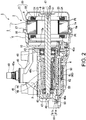
FIG. 1 is a perspective view of the wiper motor according to an embodiment of the invention. -
FIG. 2 is a cross-sectional view taken along the line A-A ofFIG. 1 . -
FIG. 3 is a cross-sectional view taken along the radial direction of the stator and the rotor according to an embodiment of the invention. -
FIG. 4 is a plan view of the rotor according to an embodiment of the invention as viewed from the axial direction. -
FIG. 5 is a plan view enlarging a part of the rotor as viewed from the axial direction, wherein (a) shows the conventional rotor and (b) shows the rotor of the present embodiment. -
FIG. 6 is an explanatory view of circumferential rattling of the permanent magnet, wherein (a) shows the conventional rotor and (b) shows the rotor of the present embodiment. -
FIG. 7 shows a part of the rotor, wherein (a) is an enlarged view of the portion B of(a) of FIG. 6 and (b) is an enlarged view of the portion C of (b) ofFIG. 6 . - Next, an embodiment of the invention will be described with reference to the drawings.
-
FIG. 1 is a perspective view of awiper motor 1.FIG. 2 is a cross-sectional view taken along the line A-A ofFIG. 1 . As shown inFIG. 1 andFIG. 2 , thewiper motor 1 serves as a drive source for a wiper mounted on a vehicle, for example. Thewiper motor 1 includes a motor part (motor) 2, adeceleration part 3 that decelerates and outputs the rotation of themotor part 2, and acontroller part 4 that controls the drive of themotor part 2. In the following description, the term "axial direction" refers to the direction of a rotational axis C1 of ashaft 31 of themotor part 2, the term "circumferential direction" refers to the circumferential direction of theshaft 31, and the term "radial direction" refers to the radial direction of theshaft 31. - The
motor part 2 includes amotor case 5, a substantiallycylindrical stator 8 housed in themotor case 5, and arotor 9 provided on the radially inner side of thestator 8 and provided to be rotatable with respect to thestator 8. Themotor part 2 is a so-called brushless motor that does not require a brush to supply electric power to thestator 8. - The
motor case 5 is made of a material having excellent heat dissipation, such as aluminum die cast. Themotor case 5 includes a first motor case 6 and a second motor case 7 which are configured so that they can be divided in the axial direction. The first motor case 6 and the second motor case 7 are each formed in a bottomed cylindrical shape. The first motor case 6 is integrally molded with agear case 40 in a manner that abottom portion 10 is joined to thegear case 40 of thedeceleration part 3. A throughhole 10a through which theshaft 31 of therotor 9 can be inserted is formed at the substantially radial center of thebottom portion 10. - In addition, an
outer flange portion 16 projecting radially outward is formed at anopening 6a of the first motor case 6. Further, anouter flange portion 17 projecting radially outward is formed at anopening 7a of the second motor case 7. Theouter flange portions motor case 5 having an internal space. Then, in the internal space of themotor case 5, the outer circumferential surface of thestator 8 is fitted to the inner circumferential surfaces of the first motor case 6 and the second motor case 7. -
FIG. 3 is a cross-sectional view taken along the radial direction of thestator 8 and therotor 9. As shown inFIG. 2 andFIG. 3 , thestator 8 has astator core 20 in which acylindrical core portion 21 having a substantially annular cross-sectional shape along the radial direction and a plurality of teeth 22 (for example, six in the present embodiment) protruding radially inward from thecore portion 21 are integrally molded. Thestator core 20 is formed by laminating a plurality of metal plates in the axial direction. Nevertheless, thestator core 20 is not necessarily formed by laminating a plurality of metal plates in the axial direction, and may be formed by, for example, pressure molding soft magnetic powder. - The
tooth 22 is integrally formed with a tooth body 101 protruding in the radial direction from the inner circumferential surface of thecore portion 21, and a collar portion 102 extending in the circumferential direction from a radially inner end of the tooth body 101. The collar portion 102 is formed to extend from the tooth body 101 toward both sides in the circumferential direction. Then, aslot 19 is formed between the circumferentially adjacent collar portions 102. - In addition, the inner circumferential surface of the
core portion 21 and theteeth 22 are covered with aninsulator 23 made of resin. Acoil 24 is wound around eachtooth 22 from above theinsulator 23. Eachcoil 24 generates a magnetic field for rotating therotor 9 by receiving power supply from thecontroller part 4. -
FIG. 4 is a plan view of therotor 9 as viewed from the axial direction. As shown inFIG. 3 andFIG. 4 , therotor 9 is rotatably provided on the radially inner side of thestator 8 via a minute gap. Therotor 9 includes ashaft 31 integrally molded with a worm shaft 44 (seeFIG. 2 ) constituting thedeceleration part 3, a substantiallycolumnar rotor core 32 fitted and fixed to the outer circumferential surface of theshaft 31 and using the axis of theshaft 31 as the rotational axis C1, and fourpermanent magnets 33 provided on the outer circumferential surface of therotor core 32. As described above, in themotor part 2, the ratio of the number of magnetic poles of thepermanent magnets 33 to the number of the slots 19 (teeth 22) is 4:6. - The
rotor core 32 is formed by laminating a plurality of metal plates in the axial direction. Nevertheless, therotor core 32 is not necessarily formed by laminating a plurality of metal plates in the axial direction, and may be formed, for example, by pressure molding soft magnetic powder. Further, a throughhole 32a penetrating in the axial direction is formed at the substantially radial center of therotor core 32. Theshaft 31 is press-fitted into the throughhole 32a. Theshaft 31 may be inserted into the throughhole 32a, and therotor core 32 may be fixed to theshaft 31 using an adhesive or the like. - Further, four
salient poles 35 are provided on the outercircumferential surface 32b of therotor core 32 at equal intervals in the circumferential direction. Thesalient pole 35 is formed to protrude radially outward and extend over theentire rotor core 32 in the axial direction. Thesalient pole 35 is formed in a rectangular shape that is long in the radial direction as viewed from the axial direction, and has salient pole side surfaces 35a on both sides in the circumferential direction and atip surface 35b on the radially outer side. On thetip surface 35b of thesalient pole 35, round chamferedportions 35c are formed at corners on both sides in the circumferential direction over the entire axial direction. Further, on thetip surface 35b of thesalient pole 35, arecess 35d is formed at the circumferential center over the entire axial direction. - An
arc portion 32c is formed at the base of thesalient pole 35, that is, at the connecting portion between the salientpole side surface 35a of thesalient pole 35 and the outercircumferential surface 32b. The salientpole side surface 35a and the outercircumferential surface 32b are connected via thearc portion 32c. An arc center C2 of the outercircumferential surface 32b of therotor core 32 is displaced radially outward and off-centered from the rotational axis C1 in a manner that the circumferential center between the circumferentially adjacentsalient poles 35 on the outercircumferential surface 32b protrudes to the radially outermost side. The outercircumferential surface 32b of therotor core 32 formed in this way is configured as amagnet housing portion 36 between two circumferentially adjacentsalient poles 35. Thepermanent magnets 33 are respectively arranged in themagnet housing portions 36. - The
permanent magnet 33 is, for example, a ferrite magnet. Thepermanent magnet 33 is formed in a substantially arc shape as viewed from the axial direction, and is formed line-symmetrically with the circumferential center as the center. Thepermanent magnet 33 has a flatmagnet side surface 33a facing the salientpole side surface 35a in the circumferential direction, an arc-shaped innercircumferential surface 33b on the radially inner side, an arc-shaped outercircumferential surface 33c on the radially outer side, aparallel surface 33d formed at the connecting portion between themagnet side surface 33a and the outercircumferential surface 33c and formed parallel on both sides in the circumferential direction, and a round chamferedportion 33e formed at the connecting portion between themagnet side surface 33a and the innercircumferential surface 33b. - The inner
circumferential surface 33b of thepermanent magnet 33 is formed in the same manner as the outercircumferential surface 32b of therotor core 32. An arc center C3 of the innercircumferential surface 33b of thepermanent magnet 33 coincides with the arc center C2 of the outercircumferential surface 32b of therotor core 32. The circumferential center of the innercircumferential surface 33b of thepermanent magnet 33 protrudes to the radially outermost side. An arc center C4 of the outercircumferential surface 33c of thepermanent magnet 33 is also displaced radially outward and off-centered from the rotational axis C1. The outercircumferential surface 33c is formed in a manner that the circumferential center protrudes to the radially outermost side. - Here, it is set that when the radius of curvature of the inner
circumferential surface 33b of thepermanent magnet 33 is Ri, and the radius of curvature of the outercircumferential surface 33c is Ro, the radii of curvature Ri and Ro satisfy: Ro > Ri ... (1). Then, the arc center C4 of the outercircumferential surface 33c of thepermanent magnet 33 coincides with the arc center C3 of the innercircumferential surface 33b of thepermanent magnet 33 and the arc center C2 of the outercircumferential surface 32b of therotor core 32. In addition, it is set that when the angle formed by the salientpole side surfaces 35a facing each other of the circumferentially adjacentsalient poles 35 is θ1, and the angle formed by the magnet side surfaces 33a on both sides of thepermanent magnet 33 in the circumferential direction is θ2, the angles θ1 and θ2 satisfy: θ1 ≒ θ2 ... (2). - Further, it is set that when the distance between the outer
circumferential surface 32b of therotor core 32 and the radially outermost end of the salientpole side surface 35a of thepermanent magnet 33, that is, the distance between the outercircumferential surface 32b excluding thearc portion 32c of therotor core 32 and the radially outermost end of thesalient pole 35, is Lt, the distance between the innercircumferential surface 33b of thepermanent magnet 33 and the radially outermost end of themagnet side surface 33a is Lme, and the radial wall thickness at the circumferential center of thepermanent magnet 33 is Lm, the distances Lt and Lme and the wall thickness Lm satisfy: Lme < Lm < Lt ... (3). - The
permanent magnet 33 is arranged in themagnet housing portion 36 of therotor core 32 and then fixed by a magnet cover 37. The magnet cover 37 is formed to cover the outercircumferential surface 33c of thepermanent magnet 33. The magnet cover 37 is formed by pressing a thin plate of magnetic material. In addition to the magnet cover 37, thepermanent magnet 33 may be attached to therotor core 32 using an adhesive or the like (not shown). With this configuration, thepermanent magnet 33 can be firmly fixed to therotor core 32. - Next, based on (a) of
FIG. 5 to(a) of FIG. 7 , the circumferential rattling of thepermanent magnet 33 of therotor 9 of the present embodiment will be described in comparison with the circumferential rattling of thepermanent magnet 133 of theconventional rotor 109.FIG. 5 is a plan view enlarging a part of the rotor as viewed from the axial direction, wherein (a) shows aconventional rotor 109 and (b) shows therotor 9 of the present embodiment. (a) and (b) ofFIG. 5 correspond toFIG. 4 described above. In the following description, in order to avoid repetition of the description of thepermanent magnet 33 in the present embodiment, each portion of therotor core 132 and thepermanent magnet 133 in theconventional rotor 109 will be described with the same name and the same reference numeral as each portion of therotor core 32 and thepermanent magnet 33 in therotor 9 of the present embodiment. - As previously mentioned, in the
rotor 9 of the present embodiment, the arc center C2 of the outercircumferential surface 32b of therotor core 32 and the arc center C3 of the innercircumferential surface 33b of thepermanent magnet 33 are displaced radially outward and off-centered from the rotational axis C1. In contrast thereto, as shown in (a) ofFIG. 5 , in theconventional rotor 109, the arc center C2 of the outercircumferential surface 32b of therotor core 132 and the arc center C3 of the innercircumferential surface 33b of thepermanent magnet 133 are not off-centered and coincide with the rotational axis C1. As shown in (a) ofFIG. 5 , a gap S1 is formed between themagnet side surface 33a on both sides of the conventionalpermanent magnet 133 in the circumferential direction and the salientpole side surface 35a facing themagnet side surface 33a in the circumferential direction. Further, as shown in (b) ofFIG. 5 , a gap S2 is formed between themagnet side surface 33a on both sides of thepermanent magnet 33 of the present embodiment in the circumferential direction and the salientpole side surface 35a facing themagnet side surface 33a in the circumferential direction. These gaps S1 and S2 have the same dimensions. -
FIG. 6 is an explanatory view of circumferential rattling of the permanent magnet, wherein (a) shows theconventional rotor 109 and (b) shows therotor 9 of the present embodiment. (a) ofFIG. 6 corresponds to (a) ofFIG. 5 described above. (b) ofFIG. 6 corresponds to (b) ofFIG. 5 described above. (a) ofFIG. 7 is an enlarged view of the portion B of (a) ofFIG. 6 .(b) of FIG. 7 is an enlarged view of the portion C of (b) ofFIG. 6 . Under the above configuration, as shown in (a) and (b) ofFIG. 6 , when thepermanent magnets salient poles 35, themagnet side surface 33a of each of thepermanent magnets pole side surface 35a. How themagnet side surface 33a comes into contact with the salientpole side surface 35a at this time differs between the present embodiment and the conventional art. - That is, with respect to the contact area of the
magnet side surface 33a with the salientpole side surface 35a in theconventional rotor 109 as shown in (a) ofFIG. 7 , the contact area of themagnet side surface 33a with the salientpole side surface 35a in therotor 9 of the present embodiment as shown in (b) ofFIG. 7 is small. More specifically, in therotor 9 of the present embodiment, only the radially outer portion of themagnet side surface 33a comes into contact with the salientpole side surface 35a (see the portion D of (b) ofFIG. 7 ). This is because the arc center C2 of the outercircumferential surface 32b of therotor core 32 and the arc center C3 of the innercircumferential surface 33b of thepermanent magnet 33 in the present embodiment are displaced radially outward and off-centered from the rotational axis C1. - In other words, if the arc centers C2 and C3 are off-centered in this way, the radii of curvature of the outer
circumferential surface 32b of therotor core 32 and the innercircumferential surface 33b of thepermanent magnet 33 become small as compared with the conventional art. Therefore, when thepermanent magnet 33 is brought close to thesalient pole 35, the inclination of themagnet side surface 33a with respect to the salientpole side surface 35a becomes large. As a result, as shown in (b) ofFIG. 7 , in therotor 9 of the present embodiment, a gap S3 remains between the radially inner side of the salientpole side surface 35a and the radially inner side of themagnet side surface 33a in a state where themagnet side surface 33a is brought into contact with the salientpole side surface 35a. - Here, in the
rotor 9 of the present embodiment, the angle θ1 formed by the salientpole side surfaces 35a facing each other of the circumferentially adjacentsalient poles 35 and the angle θ2 formed by the magnet side surfaces 33a on both sides of thepermanent magnet 33 in the circumferential direction are set to satisfy the above formula (2). Further, the distance Lt between the outercircumferential surface 32b of therotor core 32 and the radially outermost end of thesalient pole 35 and the distance Lme between the innercircumferential surface 33b of thepermanent magnet 33 and the radially outermost end of themagnet side surface 33a are set to satisfy the above formula (3). Therefore, when thepermanent magnet 33 approaches thesalient pole 35, the radially outer portion of themagnet side surface 33a is reliably brought into contact with thesalient pole 35. - Accordingly, when the
permanent magnets salient pole 35, with respect to a gap S1' between the salientpole side surface 35a and themagnet side surface 33a in theconventional rotor 109 as shown in (a) ofFIG. 6 , a gap S2' between the salientpole side surface 35a and themagnet side surface 33a in therotor 9 of the present embodiment as shown in (b) ofFIG. 6 is small. Therefore, the circumferential rattling of thepermanent magnet 33 in therotor 9 of the present embodiment is smaller than that of theconventional rotor 109. - Returning to
FIG. 1 andFIG. 2 , thedeceleration part 3 includes thegear case 40 to which themotor case 5 is attached, and aworm deceleration mechanism 41 housed in thegear case 40. Thegear case 40 is made of a material having excellent heat dissipation such as aluminum die cast. Thegear case 40 is formed in a box shape having anopening 40a on one surface, and has agear housing portion 42 housing theworm deceleration mechanism 41 inside. Further, on aside wall 40b of thegear case 40, anopening 43 for communicating the throughhole 10a of the first motor case 6 and thegear housing portion 42 is formed at a portion where the first motor case 6 is integrally molded. - Further, a substantially
cylindrical bearing boss 49 is disposed to protrude from abottom wall 40c of thegear case 40. The bearingboss 49 rotatably supports anoutput shaft 48 of theworm deceleration mechanism 41. A slide bearing (not shown) is provided on the inner circumferential surface of the bearingboss 49. An O-ring (not shown) is mounted on the inner peripheral edge of the tip of the bearingboss 49. Thus, dust and water are prevented from entering from the outside to the inside via the bearingboss 49. A plurality ofribs 52 are provided on the outer circumferential surface of the bearingboss 49. As a result, the rigidity of the bearingboss 49 is ensured. - The
worm deceleration mechanism 41 housed in thegear housing portion 42 is composed of aworm shaft 44 and aworm wheel 45 meshed with theworm shaft 44. Theworm shaft 44 is arranged coaxially with theshaft 31 of themotor part 2. Then, theworm shaft 44 is rotatably supported at both ends bybearings gear case 40. The end of theworm shaft 44 on the side of themotor part 2 protrudes through the bearing 46 to theopening 43 of thegear case 40. The protruding end of theworm shaft 44 and the end of theshaft 31 of themotor part 2 are joined, and theworm shaft 44 and theshaft 31 are integrated. Theworm shaft 44 and theshaft 31 may be integrally formed by molding a worm shaft portion and a rotation shaft portion from one base material. - The
worm wheel 45 meshed with theworm shaft 44 is provided with anoutput shaft 48 at the radial center of theworm wheel 45. Theoutput shaft 48 is arranged coaxially with the direction of the rotation shaft of theworm wheel 45. Theoutput shaft 48 protrudes through the bearingboss 49 of thegear case 40 to the outside of thegear case 40. Aspline 48a that can be connected to an electrical component (not shown) is formed at the protruding tip of theoutput shaft 48. - Furthermore, at the radial center of the
worm wheel 45, a sensor magnet (not shown) is provided on a surface opposite to the side from which theoutput shaft 48 protrudes. This sensor magnet constitutes one of the rotationposition detection part 60 that detects the rotation position of theworm wheel 45. Amagnetic detection element 61 that constitutes the other of the rotationposition detection part 60 is provided on thecontroller part 4 which is arranged to face theworm wheel 45 on the sensor magnet side (the side of theopening 40a of the gear case 40) of theworm wheel 45. - The
controller part 4 that controls the drive of themotor part 2 includes acontroller board 62 on which themagnetic detection element 61 is mounted, and acover 63 provided to close theopening 40a of thegear case 40. Then, thecontroller board 62 is arranged to face the sensor magnet side (the side of theopening 40a of the gear case 40) of theworm wheel 45. - The
controller board 62 is a so-called epoxy board on which a plurality of conductive patterns (not shown) are formed. The end portion of thecoil 24 drawn from thestator core 20 of themotor part 2 is connected to thecontroller board 62, and the terminal of the connector (none of which is shown) provided on thecover 63 is electrically connected to thecontroller board 62. Further, in addition to themagnetic detection element 61, a power module (not shown) composed of a switching element such as a FET (field effect transistor) that controls the current supplied to thecoil 24 is mounted on thecontroller board 62. Furthermore, a capacitor (not shown) or the like that smooths the voltage applied to thecontroller board 62 is mounted on thecontroller board 62. - The
cover 63 that covers thecontroller board 62 configured in this way is made of resin. Further, thecover 63 is formed to bulge slightly outward. Then, the inner surface side of thecover 63 is acontroller housing portion 56 for housing thecontroller board 62 or the like. Further, the connector (not shown) is integrally molded on the outer circumferential portion of thecover 63. This connector is formed to be fitted with a connector extending from an external power source (not shown). Then, thecontroller board 62 is electrically connected to the terminal of the connector (not shown). As a result, the electric power of the external power source is supplied to thecontroller board 62. - Here, the
controller board 62 performs advance angle energization and wide-angle energization at an electric angle θ of 121° to 180° for thecoil 24. Further, thecontroller board 62 applies a drive current with the fifth harmonic superimposed to thecoil 24. - Furthermore, on the opening edge of the
cover 63, afitting portion 81 that is fitted with an end of theside wall 40b of thegear case 40 is formed to protrude. Thefitting portion 81 is composed of twowalls cover 63. Then, the end of theside wall 40b of thegear case 40 is inserted (fitted) between these twowalls labyrinth portion 83 is formed between thegear case 40 and thecover 63. Thelabyrinth portion 83 prevents dust and water from entering from between thegear case 40 and thecover 63. Thegear case 40 and thecover 63 are fixed by fastening bolts (not shown). - Next, the operation of the
wiper motor 1 will be described. In thewiper motor 1, the electric power supplied to thecontroller board 62 via aconnector 11 is selectively supplied to eachcoil 24 of themotor part 2 via a power module (not shown). Then, the current flowing through eachcoil 24 forms a predetermined interlinkage magnetic flux on the stator 8 (teeth 22). This interlinkage magnetic flux generates a magnetic attraction force or a repulsive force (magnet torque) with the effective magnetic flux formed by thepermanent magnets 33 of therotor 9. - Further, the
salient pole 35 of therotor core 32 sets the protruding direction to a direction in which the interlinkage magnetic flux from the stator 8 (teeth 22) tends to flow, and generates a reluctance torque that rotates therotor core 32 so as to reduce the magnetic resistance (reluctance) of the magnetic path of the interlinkage magnetic flux. The torque and reluctance torque generated by thesepermanent magnets 33 continuously rotate therotor 9. - Here, on the
tip surface 35b of thesalient pole 35 in therotor core 32 of therotor 9, therecess 35d is formed at the circumferential center over the entire axial direction. Therefore, the radial interval between thetip surface 35b of thesalient pole 35 and the teeth 22 (particularly, the collar portion 22b) of thestator 8 becomes non-uniform. As a result, a sudden change in the magnetic flux density generated in the teeth 22 (particularly, the collar portion 22b) before and after thesalient pole 35 passes between theteeth 22 during the rotation of therotor 9 is suppressed, and a sudden torque fluctuation and an increase in torque ripple of therotor 9 are suppressed. - Further, the
rotor 9 has smaller circumferential rattling of thepermanent magnet 33 than theconventional rotor 109. Therotor 9 is rotated in both clockwise and counterclockwise directions as viewed from the axial direction. Thus, even if therotor 9 is rotated in both directions, the circumferential movement range of thepermanent magnet 33 with respect to therotor core 32 is suppressed as much as possible. Therefore, for example, even if the position of thepermanent magnet 33 is displaced and thepermanent magnet 33 collides with thesalient pole 35 of therotor core 32, the collision sound is reduced as much as possible. - The rotation of the
rotor 9 is transmitted to theworm shaft 44 integrated with theshaft 31, and further transmitted to theworm wheel 45 meshed with theworm shaft 44. Then, the rotation of theworm wheel 45 is transmitted to theoutput shaft 48 connected to theworm wheel 45, and theoutput shaft 48 drives a desired electrical component (for example, a wiper). - In addition, a detection signal of the rotation position of the
worm wheel 45 detected by themagnetic detection element 61 mounted on thecontroller board 62 is output to an external device (not shown). The external device (not shown) is a software function unit that functions by executing a predetermined program with a processor such as a CPU (central processing unit). The software function unit is an ECU (electronic control unit) including a processor such as a CPU, a ROM (read only memory) for storing programs, a RAM (random access memory) for temporarily storing data, and an electronic circuit such as a timer. Further, at least a part of the external device (not shown) may be an integrated circuit such as an LSI (large scale integration). - The external device (not shown) controls the switching timing of a switching element or the like of the power module (not shown) based on the rotation position detection signal of the
worm wheel 45, and controls the drive of themotor part 2. The output of the drive signal of the power module and the drive control of themotor part 2 may be executed by thecontroller part 4 instead of the external device (not shown). - As described above, in the
rotor 9 of the present embodiment, the arc center C2 of the outercircumferential surface 32b of therotor core 32 is displaced radially outward and off-centered from the rotational axis C1 in a manner that the circumferential center between the circumferentially adjacentsalient poles 35 on the outercircumferential surface 32b protrudes to the radially outermost side. Thepermanent magnet 33 is formed in a substantially arc shape as viewed from the axial direction, and is formed line-symmetrically with the circumferential center as the center. In addition, the arc center C3 of the innercircumferential surface 33b of thepermanent magnet 33 coincides with the arc center C2 of the outercircumferential surface 32b of therotor core 32. Further, the angle θ1 formed by the salientpole side surfaces 35a facing each other of the circumferentially adjacentsalient poles 35 and the angle θ2 formed by the magnet side surfaces 33a on both sides of thepermanent magnet 33 in the circumferential direction are set to satisfy the above formula (2). In addition, the distance Lt between the outercircumferential surface 32b of therotor core 32 and the radially outermost end of thesalient pole 35 and the distance Lme between the innercircumferential surface 33b of thepermanent magnet 33 and the radially outermost end of themagnet side surface 33a are set to satisfy the above formula (3). Therefore, even if the circumferential width of thepermanent magnet 33 is smaller than the width between the circumferentially adjacent salient poles 35 (see the gap S2 in (b) ofFIG. 5 ), the backlash between thesalient pole 35 and thepermanent magnet 33 prevents themagnet side surface 33a from coming into surface contact with the salientpole side surface 35a, and only the radially outermost side of themagnet side surface 33a comes into contact with thesalient pole 35. Therefore, the circumferential movement range of thepermanent magnet 33 can be narrowed, and an increase in operating noise and deterioration in rotor characteristics of therotor 9 can be suppressed. - Further, since the arc center C3 of the inner
circumferential surface 33b of thepermanent magnet 33 is displaced radially outward and off-centered from the rotational axis C1, the position of the innercircumferential surface 33b of thepermanent magnet 33 of the present embodiment can be set radially outward as compared with the position of the innercircumferential surface 33b of the conventional permanent magnet 133 (see the two-dot chain line in (b) ofFIG. 5 ). Correspondingly, the wall thickness on the side of the innercircumferential surface 33b of thepermanent magnet 33 can be cut as compared with the conventional art, and the radial wall thickness of thepermanent magnet 33 can be reduced. Therefore, the material cost for thepermanent magnet 33 can be reduced. - In addition, the arc center C4 of the outer
circumferential surface 33c of thepermanent magnet 33 is also displaced radially outward and off-centered from the rotational axis C1. The radial wall thickness Lm at the circumferential center of thepermanent magnet 33 is set to satisfy the above formula (3). Therefore, while reducing the material cost for thepermanent magnet 33, the outercircumferential surface 33c of thepermanent magnet 33 can be formed in a manner that the circumferential center protrudes to the radially outermost side, and the rotor characteristics can be improved. - Furthermore, the radius of curvature Ri of the inner
circumferential surface 33b and the radius of curvature Ro of the outercircumferential surface 33c of thepermanent magnet 33 are set to satisfy the above formula (1). Therefore, the outercircumferential surface 33c of thepermanent magnet 33 can be formed into a gentle arc shape, and the innercircumferential surface 33b can be formed into a tight arc shape with respect to the outercircumferential surface 33c. Thus, the wall thickness on the side of the innercircumferential surface 33b of thepermanent magnet 33 can be reliably cut as compared with the conventional art. Further, therotor 9 is rotated in both clockwise and counterclockwise directions as viewed from the axial direction. Thus, even if therotor 9 is rotated in both directions, the circumferential movement range of thepermanent magnet 33 with respect to therotor core 32 is suppressed as much as possible. Therefore, for example, even if the position of thepermanent magnet 33 is displaced and thepermanent magnet 33 collides with thesalient pole 35 of therotor core 32, the collision sound can be reduced as much as possible. Therefore, the above configuration can be preferably used for themotor part 2 in which therotor 9 rotates in both directions. - However, the invention is not limited to the above-described embodiment, and includes various modifications made to the above-described embodiment without departing from the spirit of the invention. For example, in the above-described embodiment, the
wiper motor 1 is taken as an example. However, besides thewiper motor 1, the above configuration of thewiper motor 1 can be adopted as a drive source of an electrical component (for example, a power window, a sunroof, an electric seat, etc.) mounted on a vehicle and for various other uses. - Further, the above-described embodiment illustrates that the arc center C4 of the outer
circumferential surface 33c of thepermanent magnet 33 is also displaced radially outward and off-centered from the rotational axis C1. However, the invention is not limited thereto, and the arc center C4 of the outercircumferential surface 33c of thepermanent magnet 33 may not be off-centered. - In addition, the above-described embodiment illustrates that the distance Lt between the outer
circumferential surface 32b of therotor core 32 and the radially outermost end of thesalient pole 35, the distance Lme between the innercircumferential surface 33b of thepermanent magnet 33 and the radially outermost end of themagnet side surface 33a, and the radial wall thickness Lm at the circumferential center of thepermanent magnet 33 are set to satisfy the above formula (3). However, the invention is not limited thereto, and it suffices if at least the distances Lt and Lme are set to satisfy Lme < Lt. With this configuration, the radially outermost side of themagnet side surface 33a can be reliably brought into contact with thesalient pole 35. - Further, the above-described embodiment illustrates that the arc center C4 of the outer
circumferential surface 33c of thepermanent magnet 33 coincides with the arc center C3 of the innercircumferential surface 33b of thepermanent magnet 33 and the arc center C2 of the outercircumferential surface 32b of therotor core 32. However, it suffices if the radius of curvature Ri of the innercircumferential surface 33b and the radius of curvature Ro of the outercircumferential surface 33c of thepermanent magnet 33 satisfy the above formula (1), and the arc center C4 of the outercircumferential surface 33c may be displaced radially outward with respect to the arc center C3 of the innercircumferential surface 33b. - 1 ... wiper motor, 2 ... motor part (motor), 3 ... deceleration part, 8 ... stator, 9 ... rotor, 22 ... teeth, 24 ... coil, 31 ... shaft, 32 ... rotor core, 32b ... outer circumferential surface, 33 ... permanent magnet, 33a ... magnet side surface (side surface), 33b ... inner circumferential surface, 33c ... outer circumferential surface, 35 ... salient pole, 35a ... salient pole side surface (side surface), C1 ... rotational axis, C2, C3, C4 ... arc center, θ1, θ2 ... angle
Claims (3)
- A rotor, comprising:a shaft rotating around a rotational axis;a rotor core fixed to the shaft and rotating with the rotational axis as a center in a radial direction;a plurality of permanent magnets arranged side by side in a circumferential direction on an outer circumferential surface of the rotor core; anda plurality of salient poles formed in a rectangular shape that is long in the radial direction as viewed from a direction of the rotational axis, protruding outward in the radial direction from the outer circumferential surface of the rotor core, and arranged between the permanent magnets adjacent to each other in the circumferential direction,wherein an arc center of the outer circumferential surface of the rotor core between the plurality of salient poles is displaced outward in the radial direction and off-centered from the rotational axis in a manner that a center in the circumferential direction between the salient poles adjacent to each other in the circumferential direction on the outer circumferential surface of the rotor core protrudes to an outermost side in the radial direction,the permanent magnet has an inner circumferential surface in an arc shape on an inner side in the radial direction as viewed from the direction of the rotational axis, and an outer circumferential surface in an arc shape on an outer side in the radial direction as viewed from the direction of the rotational axis, and is formed line-symmetrically with the center in the circumferential direction as a center,an arc center of the inner circumferential surface of the permanent magnet is displaced outward in the radial direction and off-centered from the rotational axis so as to correspond to the outer circumferential surface of the rotor core,an angle formed by side surfaces facing each other of two salient poles adjacent to each other in the circumferential direction is the same as an angle formed by side surfaces on both sides in the circumferential direction of the permanent magnet facing the side surfaces of the salient poles in the circumferential direction, andwhen a distance between the outer circumferential surface of the rotor core and an outermost end of the salient pole in the radial direction is Lt and a distance between the inner circumferential surface of the permanent magnet and an outermost end in the radial direction on the side surface of the permanent magnet is Lme, the distances Lt and Lme are set to satisfy Lme < Lt.
- A motor, comprising:a stator comprising an annular stator core, and a plurality of teeth protruding inward in the radial direction from an inner circumferential surface of the stator core;coils mounted on the teeth; andthe rotor according to claim 1 arranged on the inner side in the radial direction with respect to the plurality of teeth,wherein the rotor is rotated in both clockwise and counterclockwise directions as viewed from the direction of the rotational axis.
- A wiper motor, comprising:the motor according to claim 2; anda deceleration part decelerating and outputting rotation of the shaft.
Applications Claiming Priority (2)
| Application Number | Priority Date | Filing Date | Title |
|---|---|---|---|
| JP2018235805A JP2020099121A (en) | 2018-12-17 | 2018-12-17 | Rotor, motor, and wiper motor |
| PCT/JP2019/038725 WO2020129353A1 (en) | 2018-12-17 | 2019-10-01 | Rotor, motor, and wiper motor |
Publications (2)
| Publication Number | Publication Date |
|---|---|
| EP3902115A1 true EP3902115A1 (en) | 2021-10-27 |
| EP3902115A4 EP3902115A4 (en) | 2022-11-30 |
Family
ID=71102732
Family Applications (1)
| Application Number | Title | Priority Date | Filing Date |
|---|---|---|---|
| EP19899516.9A Pending EP3902115A4 (en) | 2018-12-17 | 2019-10-01 | ROTOR, MOTOR AND WIPER MOTOR |
Country Status (5)
| Country | Link |
|---|---|
| US (1) | US11916439B2 (en) |
| EP (1) | EP3902115A4 (en) |
| JP (2) | JP2020099121A (en) |
| CN (1) | CN113169606B (en) |
| WO (1) | WO2020129353A1 (en) |
Families Citing this family (3)
| Publication number | Priority date | Publication date | Assignee | Title |
|---|---|---|---|---|
| JP7080702B2 (en) * | 2018-04-12 | 2022-06-06 | 株式会社ミツバ | Motors and brushless wiper motors |
| JP2020099121A (en) * | 2018-12-17 | 2020-06-25 | 株式会社ミツバ | Rotor, motor, and wiper motor |
| JP2025070192A (en) * | 2023-10-19 | 2025-05-02 | 株式会社ミツバ | Rotor and manufacturing method thereof |
Family Cites Families (22)
| Publication number | Priority date | Publication date | Assignee | Title |
|---|---|---|---|---|
| JPH02111238A (en) * | 1988-10-17 | 1990-04-24 | Fanuc Ltd | Permanent magnet type synchronous motor |
| JPH02211031A (en) * | 1989-02-06 | 1990-08-22 | Teijin Seiki Co Ltd | Rotor of permanent-magnet synchronous motor |
| JPH03117338A (en) * | 1989-09-27 | 1991-05-20 | Fanuc Ltd | Rotor structure for synchronous motor |
| JP2002262533A (en) * | 2001-02-28 | 2002-09-13 | Hitachi Ltd | Permanent magnet type rotating electric machine |
| JP2004048970A (en) * | 2002-07-16 | 2004-02-12 | Meidensha Corp | Permanent-magnet rotary-electric machine |
| EP2073352B1 (en) * | 2007-12-17 | 2016-03-16 | Siemens Aktiengesellschaft | Permanently excited synchronous machine with shell magnets |
| DE112009001148B4 (en) * | 2008-05-08 | 2017-09-21 | Mitsubishi Electric Corp. | Rotating electric machine and fan using them |
| US20120001509A1 (en) * | 2010-06-30 | 2012-01-05 | Asmo Co., Ltd. | Motor and rotor |
| DE102012011445A1 (en) * | 2011-06-21 | 2012-12-27 | Asmo, Ltd. | Motor with a rotor and method of manufacturing the rotor |
| JP2015029381A (en) * | 2013-07-30 | 2015-02-12 | アスモ株式会社 | Rotor and motor |
| JP5796569B2 (en) * | 2012-12-28 | 2015-10-21 | 株式会社デンソー | Rotor and rotating electric machine using the same |
| US9515528B2 (en) * | 2014-01-06 | 2016-12-06 | Mitsubishi Electric Corporation | Permanent magnet rotary electric machine |
| JP2015204732A (en) * | 2014-04-16 | 2015-11-16 | 日本電産サンキョー株式会社 | motor |
| JP6328598B2 (en) * | 2015-10-22 | 2018-05-23 | ファナック株式会社 | Synchronous motor permanent magnet rotor |
| KR102008114B1 (en) * | 2015-11-18 | 2019-08-06 | 미쓰비시덴키 가부시키가이샤 | Electric motor and air conditioner |
| WO2018043026A1 (en) * | 2016-08-29 | 2018-03-08 | パナソニックIpマネジメント株式会社 | Surface magnet type motor |
| JP6871051B2 (en) * | 2017-04-21 | 2021-05-12 | 株式会社ミツバ | Synchronous motor and brushless motor |
| JP7169170B2 (en) * | 2018-11-15 | 2022-11-10 | 株式会社ミツバ | Rotors, motors and brushless motors |
| JP2020099121A (en) | 2018-12-17 | 2020-06-25 | 株式会社ミツバ | Rotor, motor, and wiper motor |
| JP7266180B2 (en) * | 2019-05-15 | 2023-04-28 | パナソニックIpマネジメント株式会社 | Rotor and motor with same |
| WO2021171420A1 (en) * | 2020-02-26 | 2021-09-02 | 三菱電機株式会社 | Rotor, electric motor, fan, air conditioner, and method for manufacturing rotor |
| EP4187759A4 (en) * | 2020-07-22 | 2024-01-03 | Panasonic Intellectual Property Management Co., Ltd. | ELECTRIC MOTOR |
-
2018
- 2018-12-17 JP JP2018235805A patent/JP2020099121A/en active Pending
-
2019
- 2019-10-01 WO PCT/JP2019/038725 patent/WO2020129353A1/en not_active Ceased
- 2019-10-01 US US17/312,004 patent/US11916439B2/en active Active
- 2019-10-01 EP EP19899516.9A patent/EP3902115A4/en active Pending
- 2019-10-01 CN CN201980081320.5A patent/CN113169606B/en active Active
-
2023
- 2023-03-27 JP JP2023049267A patent/JP7508629B2/en active Active
Also Published As
| Publication number | Publication date |
|---|---|
| CN113169606B (en) | 2025-11-14 |
| US11916439B2 (en) | 2024-02-27 |
| WO2020129353A1 (en) | 2020-06-25 |
| JP2020099121A (en) | 2020-06-25 |
| EP3902115A4 (en) | 2022-11-30 |
| JP7508629B2 (en) | 2024-07-01 |
| JP2023068175A (en) | 2023-05-16 |
| CN113169606A (en) | 2021-07-23 |
| US20220060069A1 (en) | 2022-02-24 |
Similar Documents
| Publication | Publication Date | Title |
|---|---|---|
| JP7508629B2 (en) | Rotor, motor, and wiper motor | |
| JP7155518B2 (en) | electric oil pump | |
| JP2008178229A (en) | Motor | |
| US12191714B2 (en) | Rotor, motor and brushless motor | |
| WO2019202916A1 (en) | Rotor, motor, and brushless wiper motor | |
| JP6870989B2 (en) | Rotor and electric motor | |
| JP7090014B2 (en) | How to manufacture rotors, motors, brushless wiper motors and rotors | |
| JP2012228024A (en) | Resolver | |
| WO2019202915A1 (en) | Motor, brushless wiper motor, and method for driving motor | |
| JP6610451B2 (en) | Motor equipment | |
| JP6655500B2 (en) | Electric motor | |
| JP7194631B2 (en) | Stator, motor and wiper motor | |
| US12119710B2 (en) | Motor having stator comprising fastening portion for suppressing tilt of the motor | |
| JP2010136590A (en) | Actuator | |
| WO2019198464A1 (en) | Motor and brushless wiper motor | |
| JP2022071593A (en) | Rotor, motor, and brushless wiper motor | |
| WO2009048181A1 (en) | Motor | |
| JP2021027717A (en) | Rotor, motor, and brushless wiper motor | |
| EP3883118B1 (en) | Motor and brushless wiper motor | |
| WO2023276678A1 (en) | Drive device | |
| CN114337088A (en) | Electric actuator | |
| JP2020178387A (en) | Motor and wiper motor | |
| JP2020108240A (en) | Servo motor | |
| CN214125011U (en) | Electric actuator | |
| JP2024064544A (en) | Rotating Electric Machine |
Legal Events
| Date | Code | Title | Description |
|---|---|---|---|
| STAA | Information on the status of an ep patent application or granted ep patent |
Free format text: STATUS: THE INTERNATIONAL PUBLICATION HAS BEEN MADE |
|
| PUAI | Public reference made under article 153(3) epc to a published international application that has entered the european phase |
Free format text: ORIGINAL CODE: 0009012 |
|
| STAA | Information on the status of an ep patent application or granted ep patent |
Free format text: STATUS: REQUEST FOR EXAMINATION WAS MADE |
|
| 17P | Request for examination filed |
Effective date: 20210611 |
|
| AK | Designated contracting states |
Kind code of ref document: A1 Designated state(s): AL AT BE BG CH CY CZ DE DK EE ES FI FR GB GR HR HU IE IS IT LI LT LU LV MC MK MT NL NO PL PT RO RS SE SI SK SM TR |
|
| DAV | Request for validation of the european patent (deleted) | ||
| DAX | Request for extension of the european patent (deleted) | ||
| A4 | Supplementary search report drawn up and despatched |
Effective date: 20221031 |
|
| RIC1 | Information provided on ipc code assigned before grant |
Ipc: H02K 7/116 20060101ALN20221025BHEP Ipc: H02K 21/16 20060101ALI20221025BHEP Ipc: H02K 1/24 20060101ALI20221025BHEP Ipc: H02K 1/278 20220101AFI20221025BHEP |
|
| REG | Reference to a national code |
Ref country code: DE Ref legal event code: R079 Free format text: PREVIOUS MAIN CLASS: H02K0001270000 Ipc: H02K0001278000 |
|
| GRAP | Despatch of communication of intention to grant a patent |
Free format text: ORIGINAL CODE: EPIDOSNIGR1 |
|
| STAA | Information on the status of an ep patent application or granted ep patent |
Free format text: STATUS: GRANT OF PATENT IS INTENDED |
|
| RIC1 | Information provided on ipc code assigned before grant |
Ipc: H02K 1/278 20220101AFI20260212BHEP Ipc: H02K 1/24 20060101ALI20260212BHEP Ipc: H02K 21/16 20060101ALI20260212BHEP Ipc: H02K 7/116 20060101ALN20260212BHEP |
|
| INTG | Intention to grant announced |
Effective date: 20260303 |
|
| GRAS | Grant fee paid |
Free format text: ORIGINAL CODE: EPIDOSNIGR3 |
|
| GRAA | (expected) grant |
Free format text: ORIGINAL CODE: 0009210 |
|
| STAA | Information on the status of an ep patent application or granted ep patent |
Free format text: STATUS: THE PATENT HAS BEEN GRANTED |