EP3902088A1 - Battery control system and saddled vehicle - Google Patents
Battery control system and saddled vehicle Download PDFInfo
- Publication number
- EP3902088A1 EP3902088A1 EP19899742.1A EP19899742A EP3902088A1 EP 3902088 A1 EP3902088 A1 EP 3902088A1 EP 19899742 A EP19899742 A EP 19899742A EP 3902088 A1 EP3902088 A1 EP 3902088A1
- Authority
- EP
- European Patent Office
- Prior art keywords
- soc
- nickel
- metal hydride
- hydride battery
- use range
- Prior art date
- Legal status (The legal status is an assumption and is not a legal conclusion. Google has not performed a legal analysis and makes no representation as to the accuracy of the status listed.)
- Granted
Links
Images








Classifications
-
- H—ELECTRICITY
- H01—ELECTRIC ELEMENTS
- H01M—PROCESSES OR MEANS, e.g. BATTERIES, FOR THE DIRECT CONVERSION OF CHEMICAL ENERGY INTO ELECTRICAL ENERGY
- H01M10/00—Secondary cells; Manufacture thereof
- H01M10/42—Methods or arrangements for servicing or maintenance of secondary cells or secondary half-cells
- H01M10/48—Accumulators combined with arrangements for measuring, testing or indicating the condition of cells, e.g. the level or density of the electrolyte
-
- H—ELECTRICITY
- H02—GENERATION; CONVERSION OR DISTRIBUTION OF ELECTRIC POWER
- H02J—ELECTRIC POWER NETWORKS; CIRCUIT ARRANGEMENTS OR SYSTEMS FOR SUPPLYING OR DISTRIBUTING ELECTRIC POWER; SYSTEMS FOR STORING ELECTRIC ENERGY
- H02J7/00—Circuit arrangements for charging or discharging batteries or for supplying loads from batteries
- H02J7/80—Circuit arrangements for charging or discharging batteries or for supplying loads from batteries including monitoring or indicating arrangements
- H02J7/82—Control of state of charge [SOC]
-
- B—PERFORMING OPERATIONS; TRANSPORTING
- B60—VEHICLES IN GENERAL
- B60L—PROPULSION OF ELECTRICALLY-PROPELLED VEHICLES; SUPPLYING ELECTRIC POWER FOR AUXILIARY EQUIPMENT OF ELECTRICALLY-PROPELLED VEHICLES; ELECTRODYNAMIC BRAKE SYSTEMS FOR VEHICLES IN GENERAL; MAGNETIC SUSPENSION OR LEVITATION FOR VEHICLES; MONITORING OPERATING VARIABLES OF ELECTRICALLY-PROPELLED VEHICLES; ELECTRIC SAFETY DEVICES FOR ELECTRICALLY-PROPELLED VEHICLES
- B60L58/00—Methods or circuit arrangements for monitoring or controlling batteries or fuel cells, specially adapted for electric vehicles
- B60L58/10—Methods or circuit arrangements for monitoring or controlling batteries or fuel cells, specially adapted for electric vehicles for monitoring or controlling batteries
- B60L58/12—Methods or circuit arrangements for monitoring or controlling batteries or fuel cells, specially adapted for electric vehicles for monitoring or controlling batteries responding to state of charge [SoC]
- B60L58/13—Maintaining the SoC within a determined range
-
- G—PHYSICS
- G01—MEASURING; TESTING
- G01R—MEASURING ELECTRIC VARIABLES; MEASURING MAGNETIC VARIABLES
- G01R31/00—Arrangements for testing electric properties; Arrangements for locating electric faults; Arrangements for electrical testing characterised by what is being tested not provided for elsewhere
- G01R31/36—Arrangements for testing, measuring or monitoring the electrical condition of accumulators or electric batteries, e.g. capacity or state of charge [SoC]
- G01R31/378—Arrangements for testing, measuring or monitoring the electrical condition of accumulators or electric batteries, e.g. capacity or state of charge [SoC] specially adapted for the type of battery or accumulator
-
- G—PHYSICS
- G01—MEASURING; TESTING
- G01R—MEASURING ELECTRIC VARIABLES; MEASURING MAGNETIC VARIABLES
- G01R31/00—Arrangements for testing electric properties; Arrangements for locating electric faults; Arrangements for electrical testing characterised by what is being tested not provided for elsewhere
- G01R31/36—Arrangements for testing, measuring or monitoring the electrical condition of accumulators or electric batteries, e.g. capacity or state of charge [SoC]
- G01R31/382—Arrangements for monitoring battery or accumulator variables, e.g. SoC
-
- H—ELECTRICITY
- H01—ELECTRIC ELEMENTS
- H01M—PROCESSES OR MEANS, e.g. BATTERIES, FOR THE DIRECT CONVERSION OF CHEMICAL ENERGY INTO ELECTRICAL ENERGY
- H01M10/00—Secondary cells; Manufacture thereof
- H01M10/34—Gastight accumulators
- H01M10/345—Gastight metal hydride accumulators
-
- H—ELECTRICITY
- H01—ELECTRIC ELEMENTS
- H01M—PROCESSES OR MEANS, e.g. BATTERIES, FOR THE DIRECT CONVERSION OF CHEMICAL ENERGY INTO ELECTRICAL ENERGY
- H01M10/00—Secondary cells; Manufacture thereof
- H01M10/42—Methods or arrangements for servicing or maintenance of secondary cells or secondary half-cells
- H01M10/425—Structural combination with electronic components, e.g. electronic circuits integrated to the outside of the casing
-
- H—ELECTRICITY
- H01—ELECTRIC ELEMENTS
- H01M—PROCESSES OR MEANS, e.g. BATTERIES, FOR THE DIRECT CONVERSION OF CHEMICAL ENERGY INTO ELECTRICAL ENERGY
- H01M10/00—Secondary cells; Manufacture thereof
- H01M10/42—Methods or arrangements for servicing or maintenance of secondary cells or secondary half-cells
- H01M10/44—Methods for charging or discharging
- H01M10/443—Methods for charging or discharging in response to temperature
-
- H—ELECTRICITY
- H02—GENERATION; CONVERSION OR DISTRIBUTION OF ELECTRIC POWER
- H02J—ELECTRIC POWER NETWORKS; CIRCUIT ARRANGEMENTS OR SYSTEMS FOR SUPPLYING OR DISTRIBUTING ELECTRIC POWER; SYSTEMS FOR STORING ELECTRIC ENERGY
- H02J7/00—Circuit arrangements for charging or discharging batteries or for supplying loads from batteries
- H02J7/90—Regulation of charging or discharging current or voltage
- H02J7/96—Regulation of charging or discharging current or voltage in response to battery voltage
-
- H—ELECTRICITY
- H02—GENERATION; CONVERSION OR DISTRIBUTION OF ELECTRIC POWER
- H02J—ELECTRIC POWER NETWORKS; CIRCUIT ARRANGEMENTS OR SYSTEMS FOR SUPPLYING OR DISTRIBUTING ELECTRIC POWER; SYSTEMS FOR STORING ELECTRIC ENERGY
- H02J7/00—Circuit arrangements for charging or discharging batteries or for supplying loads from batteries
- H02J7/90—Regulation of charging or discharging current or voltage
- H02J7/971—Regulation of charging or discharging current or voltage the charge cycle being controlled or terminated in response to non-electric parameters
- H02J7/975—Regulation of charging or discharging current or voltage the charge cycle being controlled or terminated in response to non-electric parameters in response to temperature
- H02J7/977—Regulation of charging or discharging current or voltage the charge cycle being controlled or terminated in response to non-electric parameters in response to temperature of the battery
-
- B—PERFORMING OPERATIONS; TRANSPORTING
- B60—VEHICLES IN GENERAL
- B60L—PROPULSION OF ELECTRICALLY-PROPELLED VEHICLES; SUPPLYING ELECTRIC POWER FOR AUXILIARY EQUIPMENT OF ELECTRICALLY-PROPELLED VEHICLES; ELECTRODYNAMIC BRAKE SYSTEMS FOR VEHICLES IN GENERAL; MAGNETIC SUSPENSION OR LEVITATION FOR VEHICLES; MONITORING OPERATING VARIABLES OF ELECTRICALLY-PROPELLED VEHICLES; ELECTRIC SAFETY DEVICES FOR ELECTRICALLY-PROPELLED VEHICLES
- B60L2200/00—Type of vehicles
- B60L2200/12—Bikes
-
- B—PERFORMING OPERATIONS; TRANSPORTING
- B60—VEHICLES IN GENERAL
- B60L—PROPULSION OF ELECTRICALLY-PROPELLED VEHICLES; SUPPLYING ELECTRIC POWER FOR AUXILIARY EQUIPMENT OF ELECTRICALLY-PROPELLED VEHICLES; ELECTRODYNAMIC BRAKE SYSTEMS FOR VEHICLES IN GENERAL; MAGNETIC SUSPENSION OR LEVITATION FOR VEHICLES; MONITORING OPERATING VARIABLES OF ELECTRICALLY-PROPELLED VEHICLES; ELECTRIC SAFETY DEVICES FOR ELECTRICALLY-PROPELLED VEHICLES
- B60L2240/00—Control parameters of input or output; Target parameters
- B60L2240/40—Drive Train control parameters
- B60L2240/54—Drive Train control parameters related to batteries
- B60L2240/545—Temperature
-
- B—PERFORMING OPERATIONS; TRANSPORTING
- B60—VEHICLES IN GENERAL
- B60L—PROPULSION OF ELECTRICALLY-PROPELLED VEHICLES; SUPPLYING ELECTRIC POWER FOR AUXILIARY EQUIPMENT OF ELECTRICALLY-PROPELLED VEHICLES; ELECTRODYNAMIC BRAKE SYSTEMS FOR VEHICLES IN GENERAL; MAGNETIC SUSPENSION OR LEVITATION FOR VEHICLES; MONITORING OPERATING VARIABLES OF ELECTRICALLY-PROPELLED VEHICLES; ELECTRIC SAFETY DEVICES FOR ELECTRICALLY-PROPELLED VEHICLES
- B60L2240/00—Control parameters of input or output; Target parameters
- B60L2240/40—Drive Train control parameters
- B60L2240/54—Drive Train control parameters related to batteries
- B60L2240/547—Voltage
-
- H—ELECTRICITY
- H01—ELECTRIC ELEMENTS
- H01M—PROCESSES OR MEANS, e.g. BATTERIES, FOR THE DIRECT CONVERSION OF CHEMICAL ENERGY INTO ELECTRICAL ENERGY
- H01M10/00—Secondary cells; Manufacture thereof
- H01M10/42—Methods or arrangements for servicing or maintenance of secondary cells or secondary half-cells
- H01M10/425—Structural combination with electronic components, e.g. electronic circuits integrated to the outside of the casing
- H01M2010/4271—Battery management systems including electronic circuits, e.g. control of current or voltage to keep battery in healthy state, cell balancing
-
- H—ELECTRICITY
- H01—ELECTRIC ELEMENTS
- H01M—PROCESSES OR MEANS, e.g. BATTERIES, FOR THE DIRECT CONVERSION OF CHEMICAL ENERGY INTO ELECTRICAL ENERGY
- H01M2220/00—Batteries for particular applications
- H01M2220/20—Batteries in motive systems, e.g. vehicle, ship, plane
-
- Y—GENERAL TAGGING OF NEW TECHNOLOGICAL DEVELOPMENTS; GENERAL TAGGING OF CROSS-SECTIONAL TECHNOLOGIES SPANNING OVER SEVERAL SECTIONS OF THE IPC; TECHNICAL SUBJECTS COVERED BY FORMER USPC CROSS-REFERENCE ART COLLECTIONS [XRACs] AND DIGESTS
- Y02—TECHNOLOGIES OR APPLICATIONS FOR MITIGATION OR ADAPTATION AGAINST CLIMATE CHANGE
- Y02T—CLIMATE CHANGE MITIGATION TECHNOLOGIES RELATED TO TRANSPORTATION
- Y02T10/00—Road transport of goods or passengers
- Y02T10/60—Other road transportation technologies with climate change mitigation effect
- Y02T10/7072—Electromobility specific charging systems or methods for batteries, ultracapacitors, supercapacitors or double-layer capacitors
-
- Y—GENERAL TAGGING OF NEW TECHNOLOGICAL DEVELOPMENTS; GENERAL TAGGING OF CROSS-SECTIONAL TECHNOLOGIES SPANNING OVER SEVERAL SECTIONS OF THE IPC; TECHNICAL SUBJECTS COVERED BY FORMER USPC CROSS-REFERENCE ART COLLECTIONS [XRACs] AND DIGESTS
- Y02—TECHNOLOGIES OR APPLICATIONS FOR MITIGATION OR ADAPTATION AGAINST CLIMATE CHANGE
- Y02T—CLIMATE CHANGE MITIGATION TECHNOLOGIES RELATED TO TRANSPORTATION
- Y02T90/00—Enabling technologies or technologies with a potential or indirect contribution to GHG emissions mitigation
- Y02T90/10—Technologies relating to charging of electric vehicles
- Y02T90/12—Electric charging stations
Definitions
- the present invention relates to a battery control system and a straddled vehicle having the battery control system.
- a vehicle using an internal combustion engine (hereinafter referred to as an "engine”) as its power source typically includes a rotating electrical machine installed thereon that generates electric power using the rotation of the engine.
- Patent Document Nos. 1 and 2 each disclose a straddled vehicle that uses an electric power-generating rotating electrical machine as a starter motor for driving the crank shaft of the engine at the start of the engine and as an assisting motor for assisting the power of the engine as needed while running.
- a nickel-metal hydride battery is available at relatively low cost, and it is possible to reduce the cost of the vehicle. It is possible to rotate the rotating electrical machine by supplying electric power to the rotating electrical machine from the nickel-metal hydride battery. Moreover, while generating power, the nickel-metal hydride battery can store electric power generated by the rotating electrical machine.
- a characteristic of a nickel-metal hydride battery is that the charging efficiency lowers when the temperature is high and the output lowers when the temperature is low.
- a nickel-metal hydride battery also has a problem in that it has a hysteresis and a memory effect for the relationship between voltage and SOC (State Of Charge), thereby complicating the charge/discharge control.
- a nickel-metal hydride battery for use on a vehicle, charging/discharging only over a narrow SOC range (e.g., a 40-60% range) in order to realize a stable charge/discharge control.
- a narrow SOC range e.g., a 40-60% range
- the present invention provides a battery control system, with which it is possible to precisely grasp the state of the memory effect of a nickel-metal hydride battery, and a straddled vehicle having such a battery control system.
- a battery control system is a battery control system for controlling charging/discharging of a nickel-metal hydride battery having a hysteresis characteristic for a relationship between voltage and SOC (State Of Charge), the battery control system including: a storage medium that stores information regarding a plurality of SOC use ranges having different SOC upper and lower limits; and a control circuit that selects one of the plurality of SOC use ranges depending on a condition of use of the nickel-metal hydride battery to control the charging/discharging of the nickel-metal hydride battery in accordance with the selected SOC use range, wherein: the plurality of SOC use ranges include a first use range, and a second use range that includes an SOC of the same level as the SOC lower limit of the first use range; the control circuit: determines whether a current SOC of the nickel-metal hydride battery is equal to a predetermined SOC that corresponds to the SOC lower limit of the first use range; when it is
- the discharge curves of the SOC use ranges are different from each other. Therefore, in embodiments where a plurality of SOC use ranges are selectively used, it is difficult to precisely detect the memory effect.
- the predetermined SOC that corresponds to the SOC lower limit of the first use range is included in both of the first and second use ranges. Irrespective of which one of the first and second use ranges is selected, there exists a point in time at which the SOC of the nickel-metal hydride battery becomes equal to the predetermined SOC as the SOC transitions. When it is determined that the current SOC of the nickel-metal hydride battery is equal to the predetermined SOC, information regarding the memory effect is obtained. Thus, it is possible to precisely detect the memory effect.
- the difference is small between the voltage along the discharge curve of the first use range and the voltage along the discharge curve of the second use range.
- the voltage of the nickel-metal hydride battery at a point in time when the SOC becomes equal to the predetermined SOC, at which the voltage difference is small, is detected.
- the voltage value that is detected in the region where the voltage difference is small between the SOC use ranges it is possible to precisely detect the voltage drop due to the memory effect.
- By precisely detecting the voltage drop due to the memory effect it becomes easy to repeat the charging/discharging in the selected SOC use range, and it is also possible to refresh the nickel-metal hydride battery with appropriate timing if refreshing is needed.
- the number of times the SOC of the nickel-metal hydride battery becomes equal to the predetermined SOC is counted. Based on the counted number of times, it is possible to grasp the development of the memory effect of the nickel-metal hydride battery. Then, it becomes easy to repeat the charging/discharging in the selected SOC use range, and it is also possible to refresh the nickel-metal hydride battery with appropriate timing when refreshing is needed.
- By counting the number of times at a predetermined SOC that is included in both of the first and second use ranges it is possible to precisely count the number of times without failing to count the number of times irrespective of which one of the first and second use ranges is selected.
- control circuit may: when it is determined that the current SOC is equal to the predetermined SOC, detect a voltage of the nickel-metal hydride battery at the predetermined SOC using information regarding the voltage of the nickel-metal hydride battery detected by a voltage sensor; and control the discharging of the nickel-metal hydride battery using the voltage of the nickel-metal hydride battery at the predetermined SOC.
- the difference is small between the voltage along the discharge curve of the first use range and the voltage along the discharge curve of the second use range.
- the voltage of the nickel-metal hydride battery at a point in time when the SOC becomes equal to the predetermined SOC, at which the voltage difference is small, is detected.
- control circuit may: determine whether the voltage at the predetermined SOC is less than or equal to a predetermined voltage; and when it is determined that the voltage at the predetermined SOC is less than or equal to the predetermined voltage, perform a control of refreshing the nickel-metal hydride battery.
- control circuit may correct a value of the detected voltage in accordance with the currently-selected SOC use range of the plurality of SOC use ranges.
- the voltage value at the predetermined SOC somewhat varies between different SOC use ranges. By correcting the voltage value in accordance with the currently-selected SOC use range, it is possible to more precisely detect the voltage drop due to the memory effect.
- control circuit may count the number of times the SOC of the nickel-metal hydride battery becomes equal to the predetermined SOC; determine whether the counted number of times is greater than or equal to a predetermined number of times; and when it is determined that the counted number of times is greater than or equal to the predetermined number of times, perform a control of refreshing the nickel-metal hydride battery.
- the memory effect develops, thereby decreasing the voltage that is obtained while discharging.
- the counted number of times becomes greater than or equal to the predetermined number of times, the nickel-metal hydride battery is refreshed. Thus, it is possible to restore the voltage that is obtained while discharging.
- control circuit may: count the number of times the SOC of the nickel-metal hydride battery becomes equal to the predetermined SOC; and set a lower limit of a voltage of a discharge curve of each of the plurality of SOC use ranges to be lower than a current set value depending on the counted number of times.
- the lower limit of the voltage of the discharge curve is lowered depending on the voltage drop due to the memory effect. Thus, it is possible to suppress narrowing of the SOC range that is actually used even if the memory effect develops.
- the predetermined SOC may be smaller than 50% and greater than or equal to the SOC lower limit of the first use range.
- the memory effect is likely to occur particularly in the region where SOC is less than 50% as compared with the region where SOC is 50% or more. As the region where information regarding the memory effect is obtained is set to the region where SOC is less than 50%, it is possible to perform a more appropriate discharge control.
- control circuit may: calculate a cumulative value of a current that is output from the nickel-metal hydride battery using information regarding a current of the nickel-metal hydride battery detected by a current sensor; and calculate the current SOC of the nickel-metal hydride battery using the cumulative current value.
- the SOC upper limit of the first use range may be higher than the SOC upper limit of the second use range; and the SOC lower limit of the second use range may be lower than the SOC lower limit of the first use range.
- the first use range having a high SOC upper limit and the second use range having a low SOC lower limit By selectively using the first use range having a high SOC upper limit and the second use range having a low SOC lower limit, it is possible to charge/discharge the nickel-metal hydride battery over a wide SOC range.
- the plurality of SOC use ranges may further include a third use range; an SOC upper limit of the third use range may be lower than the SOC upper limit of the first use range and higher than the SOC upper limit of the second use range; an SOC lower limit of the third use range may be lower than the SOC lower limit of the first use range and higher than the SOC lower limit of the second use range; and the third use range may include a predetermined SOC that corresponds to the SOC lower limit of the first use range.
- the predetermined SOC that corresponds to the SOC lower limit of the first use range is included in all of the first, second and third use ranges. Irrespective of which one of the first, second and third use ranges is selected, there exists a point in time at which the SOC of the nickel-metal hydride battery becomes equal to the predetermined SOC as the SOC transitions. When it is determined that the current SOC of the nickel-metal hydride battery is equal to the predetermined SOC, information regarding the memory effect is obtained. Thus, it is possible to precisely detect the memory effect.
- control circuit may change an SOC use range to be selected, from among the plurality of SOC use ranges, depending on a temperature of the nickel-metal hydride battery.
- the predetermined SOC may be of a level of the SOC lower limit of the first use range.
- the SOC of the level at the lower limit of the first use range is included in each of the use ranges. Irrespective of which one of the use ranges is selected, there exists a point in time at which the SOC of the nickel-metal hydride battery becomes equal to the predetermined SOC as the SOC transitions. When it is determined that the current SOC of the nickel-metal hydride battery is equal to the predetermined SOC, information regarding the memory effect is obtained. Thus, it is possible to precisely detect the memory effect.
- the control circuit may: charge the nickel-metal hydride battery to the SOC upper limit of the first use range; after charging the nickel-metal hydride battery to the SOC upper limit of the first use range, discharge the nickel-metal hydride battery to the lower limit of the SOC use range selected depending on a condition of use of the nickel-metal hydride battery; and after discharging the nickel-metal hydride battery to the lower limit of the selected SOC use range, charge the nickel-metal hydride battery to the SOC upper limit of the second use range selected depending on the condition of use of the nickel-metal hydride battery.
- the discharge curve and the charge curve (a discharge curve and a charge curve that are to be the reference) are obtained that connect together the SOC upper limit of the first use range and the SOC lower limit of the second use range.
- the discharge curve obtained when the second use range is selected is apart from the discharge curve to be the reference.
- the discharge curve of the second use range moves closer to the discharge curve to be the reference. If the discharge curve of the second use range moves in the process of repeating a control of changing the SOC use range, it is difficult to precisely detect the memory effect.
- the nickel-metal hydride battery is charged to the SOC upper limit of the first use range, and then discharged to the lower limit of the SOC use range selected depending on the condition of use of the nickel-metal hydride battery. After discharged to the lower limit, the nickel-metal hydride battery is charged to the upper limit of the second use range selected depending on the condition of use.
- the discharge curve of the second use range can immediately be made to conform to the discharge curve to be the reference. After the discharge curve of the second use range is made to conform to the discharge curve to be the reference, the discharge curve does not move except by the influence of the memory effect. As the discharge curve of the second use range no longer moves, it is possible to precisely detect the memory effect.
- the initial use of the nickel-metal hydride battery may be a first use of the nickel-metal hydride battery after shipping of the nickel-metal hydride battery.
- the discharge curve of the second use range can be made to conform to the discharge curve to be the reference. As the discharge curve of the second use range no longer moves except by the influence of the memory effect, it is possible to precisely detect the memory effect.
- the initial use of the nickel-metal hydride battery may be a first use of the nickel-metal hydride battery after replenishing charging of the nickel-metal hydride battery.
- the discharge curve of the second use range can be made to conform to the discharge curve to be the reference. As the discharge curve of the second use range no longer moves except by the influence of the memory effect, it is possible to precisely detect the memory effect.
- a straddled vehicle includes the battery control system described above.
- a predetermined SOC that corresponds to the SOC lower limit of the first use range is included in both of the first and second use ranges. Irrespective of which one of the first and second use ranges is selected, there exists a point in time at which the SOC of the nickel-metal hydride battery becomes equal to the predetermined SOC as the SOC transitions. When it is determined that the current SOC of the nickel-metal hydride battery is equal to the predetermined SOC, information regarding the memory effect is obtained. Thus, it is possible to precisely detect the memory effect.
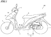
- FIG. 1 is a side view showing a motorcycle 100, which is an example of a straddled vehicle according to the embodiment of the present invention.
- the straddled vehicle is a scooter-type motorcycle.
- the straddled vehicle according to the embodiment of the present invention is not limited to a scooter-type motorcycle as illustrated herein.
- the straddled vehicle according to the embodiment of the present invention may be a motorcycle of any other type such as so-called on-road type, off-road type or moped type.
- the straddled vehicle according to the embodiment of the present invention refers to any vehicle that is straddled by a passenger, and is not limited to a two-wheeled vehicle.
- the straddled vehicle according to the embodiment of the present invention may be a three-wheeled vehicle of which the direction of travel is changed by leaning the vehicle body (LMW), or the like, or may be any other straddled vehicle such as an ATV (All Terrain Vehicle).
- LMW vehicle body
- ATV All Terrain Vehicle
- the motorcycle 100 includes a rotating electrical machine that functions as a starter/electric generator.
- the rotating electrical machine generates electric power using the rotation.
- the rotating electrical machine is used as a starter motor for driving the crank shaft of the engine at the start of the engine, and also as an assisting motor for assisting the power of the engine while running.
- the rotating electrical machine functioning as an assisting motor may be referred to herein simply as a "motor" herein.
- the motorcycle 100 shown in FIG. 1 includes a body frame 10 including a head pipe 9, a handle 4 supported on the head pipe 9, a seat 5 provided rearward of the handle 4, and a leg space 8 that is provided between the handle 4 and the seat 5 and is used by the rider to rest his/her feet thereon.
- the head pipe 9 supports a front fork 2 so that the front fork 2 can swivel left and right.
- the handle 4 is attached to the upper end of the front fork 2, and a front wheel 3 is rotatably attached to the lower end of the front fork 2.
- the seat 5 is provided on an upper portion of generally the center of the body 1.
- An ECU (Engine Control Unit) 6 and an engine unit EU are provided under the seat 5.
- the ECU 6 and the engine unit EU together form the engine system ES.
- a rear wheel 7 is rotatably attached to a lower portion of the rear end of the body 1. The rear wheel 7 is driven by the power generated by the engine unit EU.
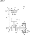
- FIG. 2 and FIG. 3 are schematic diagrams of the engine unit EU.
- the engine unit EU includes an engine 20 and a rotating electrical machine 30.
- the rotating electrical machine 30 functions as a starter/electric generator.
- FIG. 2 and FIG. 3 show a 4-stroke single-cylinder engine as an example of the engine 20.
- the engine 20 includes a cylinder CY, a piston 11, a conrod (connecting rod) 12, a crank shaft 13, an intake valve 15, an exhaust valve 16, a cam shaft 17, an injector 19 and an ignitor 18.
- the piston 11 is reciprocally provided in the cylinder CY, and is connected to the crank shaft 13 via the conrod 12.
- the cylinder CY and the piston 11 together define a combustion chamber 25.
- the combustion chamber 25 communicates with an intake passageway 22 via an intake port 21, and communicates with an exhaust passageway 24 via an exhaust port 23.
- the intake valve 15 is provided so as to open/close the intake port 21, and the exhaust valve 16 is provided so as to open/close the exhaust port 23.
- the throttle valve TL is provided along the intake passageway 22 for adjusting the flow rate of the air to be guided into the combustion chamber 25. The opening of the throttle valve TL is adjusted by operating the accelerator grip (not shown) provided on the handle 4 ( FIG. 1 ).
- the injector 19 injects fuel into the intake passageway 22.
- the ignitor 18 ignites the fuel mixture in the combustion chamber 25.
- Fuel injected by the injector 19 is mixed with the air and guided into the combustion chamber 25, and the fuel mixture is ignited in the combustion chamber 25 by the ignitor 18.
- the combustion of the fuel mixture drives the piston 11, and the reciprocation of the piston 11 is converted into the rotation of the crank shaft 13.
- the torque of the crank shaft 13 is transmitted to the rear wheel 7 of FIG. 1 , thereby driving the rear wheel 7.
- the cam shaft 17 is provided so as to rotate together with the rotation of the crank shaft 13.
- Rocker arms RA1 and RA2 are provided in contact with the cam shaft 17 so that they can swivel.
- the cam shaft 17 drives the intake valve 15 via the rocker arm RA1, and the exhaust valve 16 via the rocker arm RA2.
- a cam sprocket CS is provided at one end of the cam shaft 17.
- a cam shaft drive sprocket DS is provided on the crank shaft 13.
- a belt BL is wound between the cam sprocket CS and the cam shaft drive sprocket DS. The torque of the crank shaft 13 is transmitted to the cam shaft 17 via the belt BL.
- the rotation speed of the cam shaft 17 is 1/2 the rotation speed of the crank shaft 13, for example.
- the cam shaft 17 has cam journals 17a and 17b, an intake cam CA1 and an exhaust cam CA2.
- the cam journal 17a is arranged so as to be next to the cam sprocket CS, and the cam journal 17b is arranged at the other end of the cam shaft 17.
- the cam journals 17a and 17b are each held by a bearing (not shown) .
- the intake cam CA1 and the exhaust cam CA2 are provided between the cam journals 17a and 17b.
- the intake cam CA1 is provided so as to be next to the cam journal 17b
- the exhaust cam CA2 is provided so as to be next to the cam journal 17a.
- the intake cam CA1 drives the rocker arm RA1 of FIG. 2 when the crank angle (rotational position of the crank shaft 13) is within an angle range corresponding to the intake cycle.
- the exhaust cam CA2 drives the rocker arm RA2 of FIG. 2 when the crank angle is within an angle range corresponding to the exhaust cycle.
- a decompression mechanism DE is provided on the cam shaft 17.
- the decompression mechanism DE lifts the exhaust valve 16, independently of the exhaust cam CA2, to lower the pressure in the cylinder CY.
- the decompression mechanism is known in the art, and will not be described below.
- the rotating electrical machine 30 includes a stator 31 and a rotor 32.
- the stator 31 is secured on a crank case (not shown), and includes a plurality of stator coils 31a of U, V and W phases.
- the stator coils 31a are arranged along a circle that is centered about the rotational center of the crank shaft 13.
- the rotor 32 is secured on the crank shaft 13 so as to surround the stator 31.
- the rotor 32 includes a plurality of permanent magnets 32a.
- the plurality of permanent magnets 32a are arranged along a circle that is centered about the rotational center of the crank shaft 13.
- the rotating electrical machine 30 is capable of driving the crank shaft 13 using the electric power supplied from a nickel-metal hydride battery to be described below.
- the rotating electrical machine 30 can generate electric power from the rotation transmitted from the crank shaft 13.
- the nickel-metal hydride battery can be charged using the generated electric power. Note that a starter motor and a generator may be provided separately instead of the
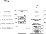
- FIG. 4 is a block diagram showing the engine system ES.
- the engine system ES operates by using electric power stored in a nickel-metal hydride battery 40 and electric power generated by the rotating electrical machine 30, for example.
- the engine system ES may include a battery for its operation, separately from the nickel-metal hydride battery 40.
- the engine system ES includes a crank angle sensor 53, a throttle opening sensor 54 and a vehicle speed sensor 55.
- the ECU 6 can detect various states of the motorcycle 100 by using the outputs from these sensors.
- the crank angle sensor 53 is a sensor for detecting the crank angle. By detecting the crank angle, it is possible to obtain the rotation speed (e.g., the number of revolutions per minute, rpm) of the engine 20.
- the throttle opening sensor 54 detects the opening of the throttle valve TL of FIG. 2 .
- the vehicle speed sensor 55 detects the running speed (vehicle speed) of the motorcycle 100.
- the crank angle sensor 53, the throttle opening sensor 54 and the vehicle speed sensor 55 each output a detection signal in accordance with the detection results to the ECU 6.
- a main switch 51 and a starter switch 52 are provided on the handle 4 ( FIG. 1 ), for example. Operation signals in accordance with the rider's operation of the main switch 51 and the starter switch 52 are output to the ECU 6.
- the nickel-metal hydride battery 40 is provided with a temperature sensor 41, a voltage sensor 42 and a current sensor 43.
- the temperature sensor 41 detects the temperature of the nickel-metal hydride battery 40.
- the temperature sensor 41 may be any temperature sensor, e.g., a thermistor, a thermocouple, etc.
- the voltage sensor 42 detects the terminal voltage of the nickel-metal hydride battery 40.
- the current sensor 43 detects the current flowing through the nickel-metal hydride battery 40.
- the temperature sensor 41, the voltage sensor 42 and the current sensor 43 each output a detection signal in accordance with the detection results to the ECU 6.
- the ECU 6 includes a microcontroller 61 and a memory 62, for example. Based on detection signals and operation signals given thereto, the ECU 6 controls the ignitor 18, the injector 19, the rotating electrical machine 30 and the nickel-metal hydride battery 40.
- the start of the engine 20 refers to the start of the combustion of a fuel mixture when the fuel injection by the injector 19 and the ignition by the ignitor 18 start.
- the stopping of the engine 20 refers to the discontinuation of the combustion of a fuel mixture following the discontinuation of at least one of the fuel injection by the injector 19 and the ignition by the ignitor 18.
- the ECU 6 of the present embodiment serves also as a battery control system for controlling the charging and discharging of the nickel-metal hydride battery 40.
- the control of the charging and discharging depending on the temperature of the nickel-metal hydride battery 40 will now be described. A control performed depending on the state of the memory effect of the nickel-metal hydride battery 40 will also be described. Note that the various numerical values shown below are illustrative, and the present invention is not limited to those numerical values.
- FIG. 5 shows a charging/discharging characteristic of the nickel-metal hydride battery 40.
- the vertical axis of FIG. 5 shows battery voltage, and the horizontal axis thereof shows SOC (State Of Charge).
- Battery voltage shown on the vertical axis is the open circuit voltage (OCV), for example.
- OCV open circuit voltage
- the microcontroller 61 can calculate the open circuit voltage by using the voltage value and the current value obtained from the voltage sensor 42 and the current sensor 43. Any of various methods known in the art can be used as the method for calculating the open circuit voltage, which will not be herein described in detail. Note that it is possible to perform the control process of the present embodiment also by using the closed circuit voltage (CCV) instead of the open circuit voltage.
- SOC shown on the horizontal axis represents, in percentage, the amount of electricity currently charged relative to the capacity of the battery.
- a discharge curve 113 shows the relationship between battery voltage and SOC when the nickel-metal hydride battery 40 is discharged from 100% SOC to 0% SOC.
- a charge curve 114 shows the relationship between battery voltage and SOC when the nickel-metal hydride battery 40 is charged from 0% SOC to 100% SOC.
- a discharge curve 123 shows the relationship between battery voltage and SOC when the nickel-metal hydride battery 40 is discharged from 90% SOC to 20% SOC.
- a charge curve 124 shows the relationship between battery voltage and SOC when the nickel-metal hydride battery 40 is charged from 20% SOC to 90% SOC.
- the memory 62 stores discharge curves, charge curves and SOC use ranges.
- the microcontroller 61 can obtain SOC from battery voltage by using a discharge curve and a charge curve read out from the memory 62.
- FIG. 5 shows an SOC use range 120.
- SOC is 90% at an upper limit 121 of the SOC use range 120 and 20% at a lower limit 122 thereof.
- the nickel-metal hydride battery 40 is charged until SOC reaches 90% and then discharged, the nickel-metal hydride battery 40 is discharged in accordance with the relationship between battery voltage and SOC along the discharge curve 123.
- the microcontroller 61 uses the output of the nickel-metal hydride battery 40 for the operation of various components of the engine system ES. For example, electric power stored in the nickel-metal hydride battery 40 is consumed by performing a control such that the rotating electrical machine 30 generates output for assisting the engine 20 while the vehicle is running.
- the nickel-metal hydride battery 40 When the nickel-metal hydride battery 40 is discharged until SOC reaches 20% and then charged, the nickel-metal hydride battery 40 is charged in accordance with the relationship between battery voltage and SOC along the charge curve 124. While charging, the microcontroller 61 performs a control such that electric power generated by the rotating electrical machine 30 is supplied to the nickel-metal hydride battery 40. Thus, the nickel-metal hydride battery 40 can be charged.
- the nickel-metal hydride battery 40 has a hysteresis characteristic wherein the discharge curve and the charge curve are significantly different from each other.
- the hysteresis characteristic of the nickel-metal hydride battery 40 complicates the charge/discharge control.
- the nickel-metal hydride battery 40 has a characteristic such that the charging efficiency lowers when the temperature is high and the output lowers when the temperature is low. Therefore, it is not easy to realize stable charging/discharging over a wide SOC use range (e.g., an SOC range from 20% to 90%).
- a plurality of SOC use ranges having different SOC upper and lower limits are selectively used depending on the temperature of the nickel-metal hydride battery 40.
- FIG. 6 shows an SOC use range 130 used when the temperature of the nickel-metal hydride battery 40 is a low temperature.
- the vertical axis of FIG. 6 shows battery voltage and the horizontal axis thereof shows SOC.
- the nickel-metal hydride battery 40 being at a low temperature means that the temperature of the nickel-metal hydride battery 40 is less than 10°C, for example.
- SOC is 90% at an upper limit 131 of the SOC use range 130 and 40% at a lower limit 132 thereof.
- the nickel-metal hydride battery 40 has a characteristic such that the output lowers when the temperature is low. Therefore, when the temperature of the nickel-metal hydride battery 40 is low, the nickel-metal hydride battery 40 is charged/discharged over a use range such that SOC does not become too low.
- the microcontroller 61 controls the charging/discharging over the SOC use range 130, which is a high value range. Thus, it is possible to suppress the lowering of the output due to the temperature of the nickel-metal hydride battery 40 being low, and to realize stable charging/discharging.
- a discharge curve 133 shows the relationship between battery voltage and SOC when the nickel-metal hydride battery 40 is discharged from 90% SOC to 40% SOC.
- a charge curve 134 shows the relationship between battery voltage and SOC when the nickel-metal hydride battery 40 is charged from 40% SOC to 90% SOC.
- the lower limit of low temperature is the lower limit temperature at which the nickel-metal hydride battery 40 is usable, for example.
- the lower limit temperature at which the nickel-metal hydride battery 40 is usable is -20°C
- the lower limit of low temperature is - 20°C.
- FIG. 7 shows an SOC use range 140 used when the temperature of the nickel-metal hydride battery 40 is a medium temperature.
- the vertical axis of FIG. 7 shows battery voltage and the horizontal axis thereof shows SOC.
- the nickel-metal hydride battery 40 being at a medium temperature means that the temperature of the nickel-metal hydride battery 40 is 10°C or more and less than 40°C, for example.
- a lower limit 142 of the SOC use range 140 shown in FIG. 7 is lower than the lower limit 132 of the SOC use range 130 shown in FIG. 6 .
- the upper limit 131 of the SOC use range 130 shown in FIG. 6 is higher than an upper limit 141 of the SOC use range 140 shown in FIG. 7 .
- SOC is 80% at the upper limit 141 of the SOC use range 140 and 30% at the lower limit 142 thereof.
- the microcontroller 61 controls the charging/discharging over the SOC use range 140.
- a discharge curve 143 shows the relationship between battery voltage and SOC when the nickel-metal hydride battery 40 is discharged from 80% SOC to 30% SOC.
- a charge curve 144 shows the relationship between battery voltage and SOC when the nickel-metal hydride battery 40 is charged from 30% SOC to 80% SOC.
- FIG. 8 shows an SOC use range 150 used when the temperature of the nickel-metal hydride battery 40 is a high temperature.
- the vertical axis of FIG. 8 shows battery voltage and the horizontal axis thereof shows SOC.
- the nickel-metal hydride battery 40 being at a high temperature means that the temperature of the nickel-metal hydride battery 40 is 40°C or more, for example.
- a lower limit 152 of the SOC use range 150 shown in FIG. 8 is lower than the lower limit 142 of the SOC use range 140 shown in FIG. 7 .
- the upper limit 141 of the SOC use range 140 shown in FIG. 7 is higher than an upper limit 151 of the SOC use range 150 shown in FIG. 8 .
- SOC is 70% at the upper limit 151 of the SOC use range 150 and 20% at the lower SOC limit 152 thereof.
- the nickel-metal hydride battery 40 has a characteristic such that the charging efficiency lowers when the temperature is high. In other words, when the temperature is high, it is difficult to charge until the SOC reaches a high value. Therefore, when the temperature of the nickel-metal hydride battery 40 is high, the nickel-metal hydride battery 40 is charged/discharged over a use range such that SOC does not become too high.
- the microcontroller 61 controls the charging/discharging over the SOC use range 150, which is a low value range.
- a discharge curve 153 shows the relationship between battery voltage and SOC when the nickel-metal hydride battery 40 is discharged from 70% SOC to 20% SOC.
- a charge curve 154 shows the relationship between battery voltage and SOC when the nickel-metal hydride battery 40 is charged from 20% SOC to 70% SOC.
- the upper limit of high temperature is the upper limit temperature at which the nickel-metal hydride battery 40 is usable, for example.
- the upper limit temperature at which the nickel-metal hydride battery 40 is usable is 60°C
- the upper limit of high temperature is 60°C.
- the memory 62 ( FIG. 4 ) stores, in advance, information regarding a plurality of SOC use ranges having different SOC upper and lower limits as described above.
- the microcontroller 61 reads out information regarding SOC use ranges from the memory 62, and sets a desired SOC use range.
- FIG. 9 is a flow chart showing a control of changing the SOC use range depending on the temperature of the nickel-metal hydride battery 40.
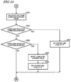
- FIG. 10 is a flow chart showing a charging/discharging control performed in accordance with the current SOC of the nickel-metal hydride battery 40.
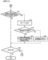
- FIG. 11 is a flow chart showing a charging/discharging control performed in conjunction with the memory effect of the nickel-metal hydride battery 40.
- step S101 the microcontroller 61 detects the temperature of the nickel-metal hydride battery 40 from the output signal of the temperature sensor 41.
- step S102 the microcontroller 61 determines whether the temperature of the nickel-metal hydride battery 40 is less than a predetermined temperature.
- the predetermined temperature is 10°C, for example.
- the microcontroller 61 selects the SOC use range 130 for low temperature (step S106). The microcontroller 61 controls the charging/discharging of the nickel-metal hydride battery 40 within the selected SOC use range 130.
- step S102 When it is determined in step S102 that the temperature of the nickel-metal hydride battery 40 is not less than the predetermined temperature, the process proceeds to step S103.
- step S103 the microcontroller 61 determines whether the temperature of the nickel-metal hydride battery 40 is in the predetermined temperature range.
- the predetermined temperature range is 10°C or more and less than 40°C, for example.
- the microcontroller 61 selects the SOC use range 140 for medium temperature (step S105). The microcontroller 61 controls the charging/discharging of the nickel-metal hydride battery 40 within the selected SOC use range 140.
- step S103 When it is determined in step S103 that the temperature of the nickel-metal hydride battery 40 is not in the predetermined temperature range, the microcontroller 61 selects the SOC use range 150 for high temperature (step S104) .
- the microcontroller 61 controls the charging/discharging of the nickel-metal hydride battery 40 within the selected SOC use range 150.
- the process changes the SOC use range to be selected from among a plurality of SOC use ranges depending on the temperature of the nickel-metal hydride battery 40.
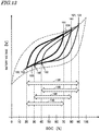
- FIG. 13 shows the SOC use range 130 for low temperature, the SOC use range 140 for medium temperature and the SOC use range 150 for high temperature.
- the vertical axis of FIG. 13 shows battery voltage and the horizontal axis thereof shows SOC.
- the microcontroller 61 performs a control of discharging the nickel-metal hydride battery 40 to the lower limit 142 of the SOC use range 140 for medium temperature. After reaching the lower limit 142, the charging of the nickel-metal hydride battery 40 is started. Thus, it is possible to change the SOC use range from the SOC use range 130 for low temperature to the SOC use range 140 for medium temperature.
- the microcontroller 61 When the SOC use range is changed from the SOC use range 140 for medium temperature to the SOC use range 150 for high temperature, the microcontroller 61 performs a control of discharging the nickel-metal hydride battery 40 to the lower limit 152 of the SOC use range 150 for high temperature. After reaching the lower limit 152, the charging of the nickel-metal hydride battery 40 is started. Thus, it is possible to change the SOC use range from the SOC use range 140 for medium temperature to the SOC use range 150 for high temperature.
- the nickel-metal hydride battery 40 when switching to a lower SOC use range, the nickel-metal hydride battery 40 is discharged to the lower limit of the target use range. Thus, it is possible to change the SOC use range.
- the microcontroller 61 performs a control of discharging the nickel-metal hydride battery 40 to the lower limit 152 of the SOC use range 150 for high temperature. After reaching the lower limit 152, the charging of the nickel-metal hydride battery 40 is started.
- the microcontroller 61 When the SOC use range is changed from the SOC use range 150 for high temperature to the SOC use range 140 for medium temperature, the microcontroller 61 performs a control of charging the nickel-metal hydride battery 40 to the upper limit 141 of the SOC use range 140 for medium temperature. After reaching the upper limit 141, the discharging of the nickel-metal hydride battery 40 is started. Thus, it is possible to change the SOC use range from the SOC use range 150 for high temperature to the SOC use range 140 for medium temperature.
- the microcontroller 61 When the SOC use range is changed from the SOC use range 140 for medium temperature to the SOC use range 130 for low temperature, the microcontroller 61 performs a control of charging the nickel-metal hydride battery 40 to the upper limit 131 of the SOC use range 130 for low temperature. After reaching the upper limit 131, the discharging of the nickel-metal hydride battery 40 is started. Thus, it is possible to change the SOC use range from the SOC use range 140 for medium temperature to the SOC use range 130 for low temperature.
- the nickel-metal hydride battery 40 is charged to the upper limit of the target use range. Thus, it is possible to change the SOC use range.
- the microcontroller 61 performs a control of charging the nickel-metal hydride battery 40 to the upper limit 131 of the SOC use range 130 for low temperature. After reaching the upper limit 131, the discharging of the nickel-metal hydride battery 40 is started. Thus, it is possible to change the SOC use range from the SOC use range 150 for high temperature to the SOC use range 130 for low temperature.
- the microcontroller 61 controls the charging/discharging of the nickel-metal hydride battery 40 in the SOC use range selected in step S104, S105, S106 of FIG. 9 . Then, the microcontroller 61 calculates the current SOC of the nickel-metal hydride battery 40 by using the cumulative value of the current that is output from the nickel-metal hydride battery 40 (step S201).
- the microcontroller 61 performs a control of charging the nickel-metal hydride battery 40 to the upper limit 131 of the SOC use range 130.
- an error can be reset at a point where the battery is charged to the upper limit of the selected SOC use range. This is because when the battery has been charged to the upper limit of the SOC use range, the precision of the relationship between voltage and SOC is high. It is possible to reduce the error in SOC by calculating the current SOC from the cumulative current value based on the SOC at the upper limit of the selected SOC use range.
- the microcontroller 61 When the nickel-metal hydride battery 40 is charged to the upper limit 131 of the SOC use range 130, the microcontroller 61 causes the nickel-metal hydride battery 40 to output a current in accordance with the action of the motorcycle 100.
- the microcontroller 61 detects the level of the current that is output from the nickel-metal hydride battery 40 based on the output signal of the current sensor 43.
- the microcontroller 61 calculates the cumulative current value from the output current and the output duration. For example, the current SOC is obtained by subtracting the cumulative current value from SOC 90% at the upper limit 131 of the SOC use range 130. By using the cumulative current value, it is possible to grasp the current SOC without using the voltage value of the nickel-metal hydride battery 40.
- step S202 the microcontroller 61 determines whether the current SOC satisfies the lower limit detection condition of the selected SOC use range.
- the lower limit detection condition is a condition that the calculated current SOC is less than or equal to the lower limit value of the selected SOC use range.
- the lower limit detection condition is a condition that the calculated current SOC is less than or equal to 40%, which is the level of the lower limit 132. Satisfying the lower limit detection condition means that the current SOC has reached, or moved past, the lower limit of the selected SOC use range.
- the microcontroller 61 sets the output limit flag to "1" (step S204).
- the microcontroller 61 controls the charging/discharging so that the amount of charging is greater than the amount of discharging.
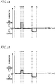
- FIG. 14 shows an example of how the nickel-metal hydride battery 40 is charged/discharged where the lower limit detection condition is not satisfied.
- FIG. 15 shows how the nickel-metal hydride battery 40 is charged/discharged where the lower limit detection condition is satisfied.
- the vertical axis of FIG. 14 and FIG. 15 shows the current that is input/output to/from the nickel-metal hydride battery 40 and the horizontal axis thereof shows time.
- the microcontroller 61 conducts a large current flow through the rotating electrical machine 30 to operate the rotating electrical machine 30, thereby starting the engine 20. While the engine 20 is rotating through the combustion of fuel, the rotating electrical machine 30 can operate as a generator. As the rotating electrical machine 30 generates electric power, the nickel-metal hydride battery 40 is charged.
- the rotating electrical machine 30 operates as an assisting motor that assists the output of the engine 20. Then, a current is supplied from the nickel-metal hydride battery 40 to the rotating electrical machine 30, and the rotating electrical machine 30 generates an assist output.
- the rotating electrical machine 30 If the passenger turns OFF the accelerator operation or performs a braking operation from time t4 to t5, the rotating electrical machine 30 generates regeneration energy, and the nickel-metal hydride battery 40 is charged.
- FIG. 15 shows how the nickel-metal hydride battery 40 is charged/discharged where the lower limit detection condition is satisfied.
- the microcontroller 61 controls the charging/discharging so that the amount of charging is greater than the amount of discharging. For example, from time t2 to t3, when the rotating electrical machine 30 generates an assist output, the current to be output from the nickel-metal hydride battery 40 is lowered, thereby suppressing the amount of discharging. It is possible to further charge the nickel-metal hydride battery 40 by keeping the amount of charging greater than the amount of discharging.
- step S203 determines whether the current SOC satisfies the upper limit detection condition of the selected SOC use range.
- the upper limit detection condition is a condition that the calculated current SOC is greater than or equal to the upper limit value of the selected SOC use range.
- the upper limit detection condition is a condition that the calculated current SOC is greater than or equal to 90%, which is the level of the upper limit 131. Satisfying the upper limit detection condition means that the current SOC has reached, or moved past, the upper limit of the selected SOC use range.
- the microcontroller 61 When it is determined that the upper limit detection condition is satisfied, the microcontroller 61 resets the cumulative current value and sets the output limit flag to "0" (steps S205 and S206). It is possible to newly calculate the current SOC from the cumulative current value based on the SOC at the upper limit of the selected SOC use range. When the output limit flag is "0", the current output limitation as illustrated in FIG. 15 is not performed.
- step S203 When it is determined in step S203 that the upper limit detection condition is not satisfied, the process proceeds to step S301 shown in FIG. 11 . Similarly, after steps S204 and S206 are performed, the process proceeds to step S301 shown in FIG. 11 .
- the lower limit detection condition is a condition that the calculated current SOC is less than or equal to the lower limit value of the selected SOC use range in the example described above
- the lower limit detection condition is not limited thereto.
- the lower limit detection condition may be a condition that the current battery voltage obtained from the output signal of the voltage sensor 42 is less than or equal to a voltage that corresponds to the lower limit SOC of the selected SOC use range.
- the voltage corresponding to the lower limit SOC is a voltage that is identified based on the relationship between the discharge curve and the level of the lower limit SOC.
- the upper limit detection condition is a condition that the calculated current SOC is greater than or equal to the upper limit value of the selected SOC use range in the example described above
- the upper limit detection condition is not limited thereto.
- the upper limit detection condition may be a condition that the current battery voltage is greater than or equal to a voltage that corresponds to the upper limit SOC of the selected SOC use range.
- the voltage corresponding to the upper limit SOC is a voltage that is identified based on the relationship between the charge curve and the level of the upper limit SOC.
- a predetermined SOC is defined as an SOC of a particular level that is included in all of the SOC use ranges 130, 140 and 150. Then, information regarding the memory effect is obtained at a point in time when the SOC of the nickel-metal hydride battery 40 becomes equal to the predetermined SOC. Thus, it is possible to precisely detect the memory effect.
- the predetermined SOC is an SOC that corresponds to the lower limit of the SOC use range 130, e.g., 40%.
- SOC 40% is an SOC of a level that is included in all of the SOC use ranges 130, 140 and 150. Therefore, irrespective of which one of the SOC use ranges 130, 140 and 150 is selected, there exists a point in time at which the SOC of the nickel-metal hydride battery 40 becomes equal to the predetermined SOC as the SOC transitions. As will be described below, information regarding the memory effect is obtained at a point in time at which the current SOC of the nickel-metal hydride battery 40 becomes equal to the predetermined SOC.
- the predetermined SOC is 40% in the description therein, the predetermined SOC is not limited thereto.
- the predetermined SOC may be of any level that is included in all of the SOC use ranges 130, 140 and 150, and it is not limited to the level of the lower limit of the use range 130.
- the predetermined SOC may be any value that is 40% or more and less than 50%.
- the memory effect is likely to occur particularly in the region where SOC is less than 50% as compared with the region where SOC is 50% or more. As the region where information regarding the memory effect is obtained is set to the region where SOC is less than 50%, it is possible to perform a more appropriate control.
- step S301 of FIG. 11 the microcontroller 61 determines whether the SOC of the nickel-metal hydride battery 40 has become equal to the predetermined SOC for the first time after reaching the upper limit of the selected SOC use range.
- the microcontroller 61 When it is determined that the current SOC of the nickel-metal hydride battery 40 is equal to the predetermined SOC, the microcontroller 61 obtains information regarding the memory effect of the nickel-metal hydride battery 40. In the example shown in FIG. 11 , the microcontroller 61 adds "1" to the count, and obtains the total count as information regarding the memory effect (step S302).
- step S303 the microcontroller 61 determines whether the count is greater than or equal to a predetermined number of times. While the predetermined number of times is 30, for example, it is not limited thereto. When it is determined that the count is greater than or equal to the predetermined number of times, the microcontroller 61 sets the memory effect saturation flag to "1" (step S305). When the memory effect saturation flag is "1", the microcontroller 61 may perform a control of refreshing the nickel-metal hydride battery 40 as will be described below.
- the memory effect develops, thereby decreasing the voltage that is obtained while discharging.
- the count becomes greater than or equal to the predetermined number of times, it is possible to restore the voltage that is obtained while discharging by refreshing the nickel-metal hydride battery 40, for example.
- step S303 When it is determined in step S303 that the count is not greater than or equal to the predetermined number of times, the process proceeds to step S304.
- step S304 the microcontroller 61 re-sets the voltage at the lower limit of each of the SOC use ranges 130, 140 and 150 depending on the development of the memory effect.
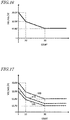
- FIG. 16 shows how the memory effect develops.
- the vertical axis of FIG. 16 shows battery voltage, and the horizontal axis thereof shows count.
- the battery voltage at the lower limit of the SOC use range lowers gradually. Then, the memory effect saturates when the count reaches 30, for example.
- FIG. 17 shows a control of lowering the lower limit voltages of the respective discharge curves 133, 143 and 153 of the SOC use ranges 130, 140 and 150 depending on the count.
- the vertical axis of FIG. 17 shows battery voltage, and the horizontal axis thereof shows count.
- the broken line 135 denotes the lower limit voltage of the discharge curve 133 of the SOC use range 130.
- the broken line 145 denotes the lower limit voltage of the discharge curve 143 of the SOC use range 140.
- the broken line 155 denotes the lower limit voltage of the discharge curve 153 of the SOC use range 150.
- the current SOC is calculated from the battery voltage
- if a voltage drop occurs due to the memory effect it may be determined that the current SOC of the nickel-metal hydride battery has reached the lower limit even though the actual SOC use range has not reached the lower limit.
- the lower limit voltage of the discharge curve is lowered depending on the degree of voltage drop due to the memory effect. Thus, it is possible to suppress narrowing of the SOC range that is actually used even if the memory effect develops.
- step S306 While the power supply of the vehicle is ON (NO in step S306), the process returns to step S101 shown in FIG. 9 , continuing the detection of the temperature.
- the currently-selected SOC use range is maintained.
- step S102 or S103 if there is a change to the temperature range, the SOC use range is changed to an SOC use range depending on the latest temperature. For example, when the temperature of the nickel-metal hydride battery 40 changes to 10°C or more and less than 40°C during a control using the SOC use range 130 for low temperature, the microcontroller 61 changes from the SOC use range 130 for low temperature to the SOC use range 140 for medium temperature.
- the microcontroller 61 changes from the SOC use range 140 for medium temperature to the SOC use range 150 for high temperature.
- a control regarding the memory effect is performed depending on the number of times the SOC of the nickel-metal hydride battery 40 becomes equal to the predetermined SOC in the description above, a control regarding the memory effect may be performed depending on the battery voltage at a point in time when the SOC of the nickel-metal hydride battery 40 becomes equal to the predetermined SOC.
- FIG. 12 is a flow chart showing a control regarding the memory effect performed depending on the battery voltage. Steps S301, S304, S305 and S306 shown in FIG. 12 are similar to those steps shown in FIG. 11 .
- step S301 shown in FIG. 12 When it is determined in step S301 shown in FIG. 12 that the current SOC of the nickel-metal hydride battery 40 is equal to the predetermined SOC, the microcontroller 61 obtains information regarding the memory effect of the nickel-metal hydride battery 40.
- the microcontroller 61 detects, from the output signal of the voltage sensor 42, the battery voltage at a point in time when the current SOC is equal to the predetermined SOC, and obtains information regarding the memory effect (step S402).
- the difference is small between the voltage along the discharge curve of the SOC use range 130, the voltage along the discharge curve of the SOC use range 140 and the voltage along the discharge curve of the SOC use range 150.
- the voltage of the nickel-metal hydride battery 40 at a point in time when the SOC becomes equal to the predetermined SOC, at which the voltage difference is small, is detected.
- step S403 the microcontroller 61 determines whether the detected battery voltage is less than or equal to a predetermined voltage. While the predetermined voltage is 12.8 V, for example, the predetermined voltage is not limited thereto. When it is determined that the detected battery voltage is less than or equal to the predetermined voltage, the microcontroller 61 sets the memory effect saturation flag to "1" (step S305). When the memory effect saturation flag is "1", the microcontroller 61 may perform a control of refreshing the nickel-metal hydride battery 40 as will be described below.
- step S403 When it is determined in step S403 that the detected battery voltage is not less than or equal to the predetermined voltage, the process proceeds to step S304.
- step S304 the microcontroller 61 re-sets the voltage at the lower limit of each of the SOC use ranges 130, 140 and 150 depending on the development of the memory effect.
- Re-setting of the lower limit voltage may be performed depending on the count as described above using FIG. 17 , or may be performed depending on the degree of battery voltage drop at a point in time when the SOC of the nickel-metal hydride battery 40 becomes equal to the predetermined SOC.
- the lower limit of the voltage of the discharge curve is lowered depending on the voltage drop due to the memory effect. Thus, it is possible to suppress narrowing of the SOC range that is actually used even if the memory effect develops.
- microcontroller 61 may correct the value of the battery voltage that is detected at a point in time when the current SOC is equal to the predetermined SOC, in accordance with the currently-selected SOC use range of the SOC use ranges 130, 140 and 150.
- the voltage value at the predetermined SOC somewhat varies between different SOC use ranges. By correcting the voltage value in accordance with the currently-selected SOC use range, it is possible to more precisely detect the voltage drop due to the memory effect.
- step S403 the corrected value and the predetermined voltage are compared with each other.
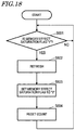
- FIG. 18 is a flow chart showing a control of refreshing the nickel-metal hydride battery 40.
- the microcontroller 61 may perform a control of refreshing the nickel-metal hydride battery 40.
- step S501 the microcontroller 61 determines whether the memory effect saturation flag is "1". When it is determined that the memory effect saturation flag is not "1", the determination is periodically repeated until the memory effect saturation flag becomes "1".
- the microcontroller 61 refreshes the nickel-metal hydride battery 40 (step S502).
- the nickel-metal hydride battery 40 is discharged until the voltage of the nickel-metal hydride battery 40 reaches the discharge termination voltage, for example.
- the nickel-metal hydride battery 40 is charged to the upper limit 131 of the SOC use range 130. Thus, it is possible to restore the battery voltage that is obtained while discharging.
- step S503 After refreshing the nickel-metal hydride battery 40, the microcontroller 61 sets the memory effect saturation flag to "0" (step S503). The number of times that is counted in step S302 ( FIG. 11 ) is reset (step S504). Then, referring back to step S501, the determination is periodically repeated until the memory effect saturation flag becomes "1" the next time.
- the initial discharge of the nickel-metal hydride battery 40 is, for example, the first discharge after shipping of the nickel-metal hydride battery 40.
- FIG. 13 shows a charging/discharging characteristic after the elapse of a certain period of time or longer since the start of use of the nickel-metal hydride battery 40 after shipping. For example, it shows a charging/discharging characteristic that is obtained after repeating a control of changing the SOC use range depending on the temperature.
- the relationship between battery voltage and SOC at the lower limit 152 of the SOC use range 150 is along the discharge curve 123.
- the relationship between battery voltage and SOC at the lower limit 142 of the SOC use range 140 is along the discharge curve 123.
- the relationship between battery voltage and SOC at the upper limit 151 of the SOC use range 150 is along the charge curve 124.
- the relationship between battery voltage and SOC at the upper limit 141 of the SOC use range 140 is along the charge curve 124.
- the discharge curve 123 is a discharge curve that is obtained by discharging from the upper limit 131 of the SOC use range 130 to the lower limit 152 of the SOC use range 150.
- the charge curve 124 is a charge curve that is obtained by charging from the lower limit 152 of the SOC use range 150 to the upper limit 131 of the SOC use range 130.
- FIG. 19 shows a charging/discharging characteristic when a period has not elapsed since the first use of the nickel-metal hydride battery 40 after shipping.
- the vertical axis of FIG. 19 shows battery voltage, and the horizontal axis thereof shows SOC.
- the relationship between battery voltage and SOC at the lower limit 152 of the SOC use range 150 is apart from the discharge curve 123.
- the relationship between battery voltage and SOC at the lower limit 142 of the SOC use range 140 is apart from the discharge curve 123.
- the relationship between battery voltage and SOC at the upper limit 151 of the SOC use range 150 is apart from the charge curve 124.
- the relationship between battery voltage and SOC at the upper limit 141 of the SOC use range 140 is apart from the charge curve 124.
- FIG. 20 shows how the discharge curves 143 and 153 and the charge curves 144 and 154 move.
- the graph on the left side of FIG. 20 shows a charging/discharging characteristic of the nickel-metal hydride battery 40 immediately after shipping.
- the graph on the right side of FIG. 20 shows a charging/discharging characteristic after the discharge curves 143 and 153 and the charge curves 144 and 154 have moved.
- the vertical axis of FIG. 20 shows battery voltage, and the horizontal axis thereof shows SOC.
- the nickel-metal hydride battery 40 exhibits a different charging/discharging characteristic depending on the status of charge.
- the nickel-metal hydride battery 40 that has been charged to the upper limit 151 of the SOC use range 150 has the discharge curve 153 and the charge curve 154 that are based on the upper limit 151.
- the nickel-metal hydride battery 40 that has been charged to the upper limit 141 of the SOC use range 140 has the discharge curve 143 and the charge curve 144 that are based on the upper limit 141.
- the discharge curves 143 and 153 and the charge curves 144 and 154 move closer to the discharge curve 123 and the charge curve 124 that are based on the upper limit 131. If the discharge curves 143 and 153 move during use as described above, it is difficult to precisely detect the memory effect.
- the nickel-metal hydride battery 40 is charged to the upper limit 131 of the SOC use range 130 at the time of initial charging/discharging.
- the upper limit 131 is of the same level as the upper limit 121. If the nickel-metal hydride battery 40 is self-discharging at the time of initial charging/discharging, the nickel-metal hydride battery 40 is charged to the upper limit 131 of the SOC use range 130 at the time of initial charging/discharging. After the nickel-metal hydride battery 40 is charged to the upper limit 131, the nickel-metal hydride battery 40 is discharged to the lower limit of the SOC use range depending on the temperature condition.
- the discharge curves 143 and 153 can be made to extend along the discharge curve 123 to be the reference. After the discharge curves 143 and 153 are made to extend along the discharge curve 123 to be the reference, the discharge curves 143 and 153 no longer move except by the influence of the memory effect. As the discharge curves 143 and 153 no longer move except by the influence of the memory effect, it is possible to precisely detect the memory effect.
- FIG. 21 and FIG. 22 are flow charts showing an initial charge/discharge control of the nickel-metal hydride battery 40.
- step S601 the microcontroller 61 determines whether the initialization flag is "1".
- the initialization flag is stored in the memory 62, for example. Where the process shown in steps S603 to S612 to be described below has not been performed, the initialization flag represents "0". Where the process shown in steps S603 to S612 has been completed, the initialization flag represents "1".
- the microcontroller 61 executes the process of changing the SOC use range depending on the temperature shown in FIG. 9 .
- the microcontroller 61 determines whether the temperature of the nickel-metal hydride battery 40 is a high temperature (step S602). As described above, the nickel-metal hydride battery 40 being at a high temperature means that the temperature of the nickel-metal hydride battery 40 is at 40°C or more, for example.
- the microcontroller 61 executes the process of changing the SOC use range depending on the temperature shown in FIG. 9 .
- the temperature of the nickel-metal hydride battery 40 is high, it is difficult to charge the nickel-metal hydride battery 40 to a high value such as SOC 90%. Therefore, when the nickel-metal hydride battery 40 is at a high temperature, the process shown in steps S603 to S612 is not performed.
- the determination of step S601 is performed again. While the operating environment of the motorcycle 100 continues to be a high temperature, the process shown in steps S603 to S612 is not performed. However, while a high-temperature operating environment continues, a control of selectively using a plurality of SOC use ranges is not performed, and there is no need to perform charging/discharging as shown in steps S603 to S612.
- the microcontroller 61 sets the output limit flag to "1" and starts charging the nickel-metal hydride battery 40 (step S603).
- the output limit flag is set to "1", and a control is performed so that the amount of charging is greater than the amount of discharging. Discharging is kept to the minimum necessary, e.g., limited to discharging at the start-up of the engine 20.
- the microcontroller 61 continues to charge the nickel-metal hydride battery 40 until the upper limit 131 of the SOC use range 130 is reached (step S604).
- the microcontroller 61 When it is determined that the nickel-metal hydride battery 40 has been charged to reach the upper limit 131 of the SOC use range 130, the microcontroller 61 starts discharging the nickel-metal hydride battery 40. As will be described below, the microcontroller 61 continues to discharge the nickel-metal hydride battery 40 until the lower limit of the SOC use range depending on the temperature condition is reached. Discharging is kept to the minimum necessary, e.g., limited only to the regenerative operation while decelerating and stopping.
- step S605 the microcontroller 61 determines whether the temperature of the nickel-metal hydride battery 40 is less than a predetermined temperature.
- the predetermined temperature is 10°C, for example.
- the microcontroller 61 selects the SOC use range 130 for low temperature (step S609) .
- the microcontroller 61 starts discharging the nickel-metal hydride battery 40 within the selected SOC use range 130 (step S610).
- the output limit flag is set to "0".
- step S605 When it is determined in step S605 that the temperature of the nickel-metal hydride battery 40 is not less than a predetermined temperature, the process proceeds to step S606.
- step S606 the microcontroller 61 determines whether the temperature of the nickel-metal hydride battery 40 is in a predetermined temperature range.
- the predetermined temperature range is 10°C or more and less than 40°C, for example.
- the microcontroller 61 selects the SOC use range 140 for medium temperature (step S608).
- the microcontroller 61 starts discharging the nickel-metal hydride battery 40 within the selected SOC use range 140 (step S610).
- step S606 When it is determined in step S606 that the temperature of the nickel-metal hydride battery 40 is not in the predetermined temperature range, the microcontroller 61 selects the SOC use range 150 for high temperature (step S607) . The microcontroller 61 starts discharging the nickel-metal hydride battery 40 within the selected SOC use range 150 (step S610) .
- the microcontroller 61 continues to discharge the nickel-metal hydride battery 40 until the lower limit of the selected SOC use range is reached (step S611) .
- the initialization flag is set to "1" (step S612).
- the process proceeds to steps S101 to S106 of FIG. 9 , and steps S201 to S206 of FIG. 10 .
- the output limit flag is always "1" in step S202, and a control is performed so that the amount of charging is greater than the amount of discharging.
- the charge curves 144 and 154 change so as to conform to the charge curve 124.
- the output limit flag is set to "0", and a control is performed so that the amount of discharging is greater than the amount of charging.
- the discharge curve 143 changes so as to conform to the discharge curve 123.
- the discharge curve 153 changes so as to conform to the discharge curve 123.
- the discharge curves 143 and 153 can be made to conform to the discharge curve 123. After performing such initial charging/discharging, the control regarding the memory effect described above is executed. As the discharge curves 143 and 153 do not move except by the influence of the memory effect, it is possible to precisely detect the memory effect.
- the initial discharge of the nickel-metal hydride battery 40 is the first discharge after shipping of the nickel-metal hydride battery 40 in the example described above, the initial discharge may be the first discharge after supplemental charging of the nickel-metal hydride battery 40.
- the discharge curves 143 and 153 can be made to conform to the discharge curve 123. As the discharge curves 143 and 153 do not move except by the influence of the memory effect, it is possible to precisely detect the memory effect even after replenishing charging.
- SOC use ranges are selectively used depending on the temperature in the description above, the present invention is not limited thereto.
- the number of SOC use ranges to be selectively used depending on the temperature may be two or may be four or more.
- a battery control system 6 controls the charging/discharging of the nickel-metal hydride battery 40 having a hysteresis characteristic for the relationship between voltage and SOC (State Of Charge).
- the battery control system 6 includes the memory 62 (storage medium) for storing information regarding the SOC use ranges 130, 140 and 150 having different SOC upper and lower limits, and the microcontroller 61 (control circuit) for selecting one of the SOC use ranges 130, 140 and 150 depending on the condition of use of the nickel-metal hydride battery 40 and performing a charge/discharge control of the nickel-metal hydride battery 40 in accordance with the selected SOC use range.
- the SOC use ranges include the first use range 130, and the second use ranges 140 and 150 each including an SOC of the same level as the SOC lower limit 132 of the first use range 130.
- the microcontroller 61 determines whether the current SOC of the nickel-metal hydride battery 40 is equal to a predetermined SOC that corresponds to the SOC lower limit 132 of the first use range 130. When it is determined that the current SOC of the nickel-metal hydride battery 40 is equal to the predetermined SOC, the microcontroller 61 obtains information regarding the memory effect of the nickel-metal hydride battery 40 and controls the discharge of the nickel-metal hydride battery 40 using the obtained information regarding the memory effect.
- the discharge curves of the SOC use ranges 130, 140 and 150 are different from each other. Therefore, in embodiments where the SOC use ranges 130, 140 and 150 are selectively used, it is difficult to precisely detect the memory effect.
- a predetermined SOC that corresponds to the SOC lower limit 132 of the first use range 130 is included in all of the first and second use ranges 130, 140 and 150. Irrespective of which one of the first and second use ranges 130, 140 and 150 is selected, there exists a point in time at which the SOC of the nickel-metal hydride battery 40 becomes equal to the predetermined SOC as the SOC transitions. When it is determined that the current SOC of the nickel-metal hydride battery 40 is equal to the predetermined SOC, information regarding the memory effect is obtained. Then, it is possible to precisely detect the memory effect.
- the difference is small between the voltage along the discharge curve of the first use range 130 and the voltage along the discharge curve of the second use ranges 140 and 150.
- the voltage of the nickel-metal hydride battery 40 at a point in time when the SOC becomes equal to the predetermined SOC, at which the voltage difference is small, is detected.
- the voltage value that is detected in the region where the voltage difference is small between the SOC use ranges 130, 140 and 150 it is possible to precisely detect the voltage drop due to the memory effect.
- By precisely detecting the voltage drop due to the memory effect it becomes easy to repeat the charging/discharging in the selected SOC use range, and it is also possible to refresh the nickel-metal hydride battery 40 with appropriate timing if refreshing is needed.
- the number of times the SOC of the nickel-metal hydride battery 40 becomes equal to the predetermined SOC is counted. Based on the counted number of times, it is possible to grasp the development of the memory effect of the nickel-metal hydride battery 40. Then, it becomes easy to repeat the charging/discharging in the selected SOC use range, and it is also possible to refresh the nickel-metal hydride battery 40 with appropriate timing if refreshing is needed.
- By counting the number of times at a predetermined SOC that is included in all of the first and second use ranges 130, 140 and 150 it is possible to precisely count the number of times without failing to count the number of times irrespective of which one of the first and second use ranges 130, 140 and 150 is selected.
- the microcontroller 61 may detect the voltage of the nickel-metal hydride battery 40 at the predetermined SOC by using information regarding the voltage of the nickel-metal hydride battery 40 detected by the voltage sensor 42, and control the discharge of the nickel-metal hydride battery 40 by using the voltage of the nickel-metal hydride battery 40 at the predetermined SOC.
- the difference is small between the voltage along the discharge curve of the first use range 130 and the voltage along the discharge curve of the second use ranges 140 and 150.
- the voltage of the nickel-metal hydride battery 40 at a point in time when the SOC becomes equal to the predetermined SOC, at which the voltage difference is small, is detected.
- a control of refreshing the nickel-metal hydride battery 40 may be performed.
- the microcontroller 61 may correct the value of the detected voltage in accordance with the currently-selected SOC use range of the SOC use ranges 130, 140 and 150.
- the voltage value at the predetermined SOC somewhat varies between different SOC use ranges. By correcting the voltage value in accordance with the currently-selected SOC use range, it is possible to more precisely detect the voltage drop due to the memory effect.
- the microcontroller 61 may count the number of times the SOC of the nickel-metal hydride battery 40 becomes equal to the predetermined SOC, determine whether the counted number of times is greater than or equal to a predetermined number of times, and if the counted number of times is greater than or equal to the predetermined number of times, perform a control of refreshing the nickel-metal hydride battery 40.
- the memory effect develops, thereby decreasing the voltage that is obtained while discharging.
- the counted number of times becomes greater than or equal to the predetermined number of times, the nickel-metal hydride battery 40 is refreshed. Thus, it is possible to restore the voltage that is obtained while discharging.
- the microcontroller 61 may count the number of times the SOC of the nickel-metal hydride battery 40 becomes equal to the predetermined SOC, and set the lower limits of the voltages of the discharge curves of the SOC use ranges 130, 140 and 150 to be lower than the current set values depending on the counted number of times.
- the lower limit of the voltage of the discharge curve is lowered depending on the voltage drop due to the memory effect. Thus, it is possible to suppress narrowing of the SOC range that is actually used even if the memory effect develops.
- the predetermined SOC may be lower than 50% and greater than or equal to the SOC lower limit 132 of the first use range 130.
- the memory effect is likely to occur particularly in the region where SOC is less than 50% as compared with the region where SOC is 50% or more. As the region where information regarding the memory effect is obtained is set to the region where SOC is less than 50%, it is possible to perform a more appropriate discharge control.
- the microcontroller 61 may use information regarding the current of the nickel-metal hydride battery 40 detected by the current sensor 43 to calculate the cumulative value of the current that is output from the nickel-metal hydride battery 40 and calculate the current SOC of the nickel-metal hydride battery 40 using the cumulative value of the current.
- the SOC upper limit 131 of the first use range 130 may be higher than the SOC upper limits 141 and 151 of the second use ranges 140 and 150, and the SOC lower limits 142 and 152 of the second use ranges 140 and 150 may be lower than the SOC lower limit 132 of the first use range 130.
- a plurality of SOC use ranges further include the third use range 140, wherein the SOC upper limit 141 of the third use range 140 is lower than the SOC upper limit 131 of the first use range 130 and higher than the SOC upper limit 151 of the second use range 150, the SOC lower limit 142 of the third use range 140 is lower than the SOC lower limit 132 of the first use range 130 and higher than the SOC lower limit 152 of the second use range 150, and the third use range 140 may include a predetermined SOC that corresponds to the SOC lower limit 132 of the first use range 130.
- the predetermined SOC that corresponds to the SOC lower limit 132 of the first use range 130 is included in all of the first, second and third use ranges 130, 140 and 150. Irrespective of which one of the first, second and third use ranges 130, 140 and 150 is selected, there exists a point in time at which the SOC of the nickel-metal hydride battery 40 becomes equal to the predetermined SOC as the SOC transitions. When it is determined that the current SOC of the nickel-metal hydride battery 40 is equal to the predetermined SOC, information regarding the memory effect is obtained. Then, it is possible to precisely detect the memory effect.
- the microcontroller 61 may change the SOC use range to be selected, from among the SOC use ranges 130, 140 and 150, depending on the temperature of the nickel-metal hydride battery 40.
- the predetermined SOC may be the level of the SOC lower limit 132 of the first use range 130.
- the SOC of the level at the lower limit 132 of the first use range 130 is included in each of the use ranges 130, 140 and 150. Irrespective of which one of the use ranges 130, 140 and 150 is selected, there exists a point in time at which the SOC of the nickel-metal hydride battery 40 becomes equal to the predetermined SOC as the SOC transitions. When it is determined that the current SOC of the nickel-metal hydride battery 40 is equal to the predetermined SOC, information regarding the memory effect is obtained. Thus, it is possible to precisely detect the memory effect.
- the microcontroller 61 may perform a control of: charging the nickel-metal hydride battery 40 to the SOC upper limit 131 of the first use range 130; discharging the nickel-metal hydride battery 40 to the lower limit of the SOC use range selected depending on the condition of use of the nickel-metal hydride battery 40 after charging the nickel-metal hydride battery 40 to the SOC upper limit 131 of the first use range 130; and charging the nickel-metal hydride battery 40 to the SOC upper limit 141, 151 of the second use range 140, 150 selected depending on the condition of use of the nickel-metal hydride battery 40 after discharging the nickel-metal hydride battery 40 to the lower limit of the selected SOC use range.
- the discharge curve 123 and the charge curve 124 (a discharge curve and a charge curve that are to be the reference) are obtained that connect together the SOC upper limit 131 of the first use range 130 and the SOC lower limit 152 of the second use range 150.
- the discharge curve obtained when the second use ranges 140 and 150 are selected is apart from the discharge curve to be the reference.
- the discharge curves of the second use ranges 140 and 150 move closer to the discharge curve to be the reference. If the discharge curves of the second use ranges 140 and 150 move in the process of repeating a control of changing the SOC use range, it is difficult to precisely detect the memory effect.
- the nickel-metal hydride battery 40 is charged to the SOC upper limit 131 of the first use range 130, and then discharged to the lower limit of the SOC use range selected depending on the condition of use of the nickel-metal hydride battery 40. After discharged to the lower limit, the nickel-metal hydride battery 40 is charged to the upper limit 141, 151 of the second use range 140, 150 selected depending on the condition of use.
- the discharge curves of the second use ranges 140 and 150 can immediately be made to conform to the discharge curve to be the reference.
- the discharge curves of the second use ranges 140 and 150 are made to conform to the discharge curve to be the reference, the discharge curves do not move except by the influence of the memory effect. As the discharge curves of the second use ranges 140 and 150 no longer move except by the influence of the memory effect, it is possible to precisely detect the memory effect.
- the initial use of the nickel-metal hydride battery 40 may be the first use of the nickel-metal hydride battery 40 after shipping.
- the discharge curves of the second use ranges 140 and 150 can be made to confirm to the discharge curve to be the reference. As the discharge curves of the second use ranges 140 and 150 no longer move except by the influence of the memory effect, it is possible to precisely detect the memory effect.
- the initial use of the nickel-metal hydride battery 40 may be the first use of the nickel-metal hydride battery 40 after replenishing charging.
- the discharge curves of the second use ranges 140 and 150 can be made to conform to the discharge curve to be the reference. As the discharge curves of the second use ranges 140 and 150 no longer move except by the influence of the memory effect, it is possible to precisely detect the memory effect.
- a straddled vehicle 100 includes the battery control system 6 described above.
- the present invention is particularly useful in technical fields where a nickel-metal hydride battery is charged/discharged.
Landscapes
- Engineering & Computer Science (AREA)
- Manufacturing & Machinery (AREA)
- Chemical & Material Sciences (AREA)
- Chemical Kinetics & Catalysis (AREA)
- Electrochemistry (AREA)
- General Chemical & Material Sciences (AREA)
- Power Engineering (AREA)
- Physics & Mathematics (AREA)
- General Physics & Mathematics (AREA)
- Sustainable Development (AREA)
- Transportation (AREA)
- Mechanical Engineering (AREA)
- Microelectronics & Electronic Packaging (AREA)
- Sustainable Energy (AREA)
- Life Sciences & Earth Sciences (AREA)
- Charge And Discharge Circuits For Batteries Or The Like (AREA)
- Secondary Cells (AREA)
- Electric Propulsion And Braking For Vehicles (AREA)
Abstract
Description
- The present invention relates to a battery control system and a straddled vehicle having the battery control system.
- A vehicle using an internal combustion engine (hereinafter referred to as an "engine") as its power source typically includes a rotating electrical machine installed thereon that generates electric power using the rotation of the engine.
- Patent Document Nos. 1 and 2 each disclose a straddled vehicle that uses an electric power-generating rotating electrical machine as a starter motor for driving the crank shaft of the engine at the start of the engine and as an assisting motor for assisting the power of the engine as needed while running.
-
- Patent Document No. 1:
Japanese Laid-Open Patent Publication No. 2004-122925 - Patent Document No. 2:
Japanese Laid-Open Patent Publication No. 2008-24255 - One may consider using a nickel-metal hydride battery as the secondary battery of such a rotating electrical machine. A nickel-metal hydride battery is available at relatively low cost, and it is possible to reduce the cost of the vehicle. It is possible to rotate the rotating electrical machine by supplying electric power to the rotating electrical machine from the nickel-metal hydride battery. Moreover, while generating power, the nickel-metal hydride battery can store electric power generated by the rotating electrical machine.
- However, a characteristic of a nickel-metal hydride battery is that the charging efficiency lowers when the temperature is high and the output lowers when the temperature is low. A nickel-metal hydride battery also has a problem in that it has a hysteresis and a memory effect for the relationship between voltage and SOC (State Of Charge), thereby complicating the charge/discharge control.
- With this characteristic of a nickel-metal hydride battery, one may consider, for a nickel-metal hydride battery for use on a vehicle, charging/discharging only over a narrow SOC range (e.g., a 40-60% range) in order to realize a stable charge/discharge control. By limiting the SOC use range to a narrow range, it is possible to realize a stable control that reduces the influence of the lowering of the charging efficiency and the lowering of the output.
- On the other hand, in order to make effective use of the performance of a nickel-metal hydride battery, it is desirable to charge/discharge over a wide SOC range. In order to appropriately control charging/discharging over a wide SOC range, it is desirable to precisely grasp the state of the memory effect of the nickel-metal hydride battery.
- The present invention provides a battery control system, with which it is possible to precisely grasp the state of the memory effect of a nickel-metal hydride battery, and a straddled vehicle having such a battery control system.
- A battery control system according to an embodiment of the present invention is a battery control system for controlling charging/discharging of a nickel-metal hydride battery having a hysteresis characteristic for a relationship between voltage and SOC (State Of Charge), the battery control system including: a storage medium that stores information regarding a plurality of SOC use ranges having different SOC upper and lower limits; and a control circuit that selects one of the plurality of SOC use ranges depending on a condition of use of the nickel-metal hydride battery to control the charging/discharging of the nickel-metal hydride battery in accordance with the selected SOC use range, wherein: the plurality of SOC use ranges include a first use range, and a second use range that includes an SOC of the same level as the SOC lower limit of the first use range; the control circuit: determines whether a current SOC of the nickel-metal hydride battery is equal to a predetermined SOC that corresponds to the SOC lower limit of the first use range; when it is determined that the current SOC is equal to the predetermined SOC, obtains information regarding a memory effect of the nickel-metal hydride battery; and controls the discharging of the nickel-metal hydride battery using the obtained information regarding the memory effect.
- By selectively using a plurality of SOC use ranges depending on the condition of use of the nickel-metal hydride battery, it is possible to charge/discharge over a wide SOC range. Being able to charge/discharge over a wide SOC range, it is possible to make effective use of the performance of the nickel-metal hydride battery.
- On the other hand, the discharge curves of the SOC use ranges are different from each other. Therefore, in embodiments where a plurality of SOC use ranges are selectively used, it is difficult to precisely detect the memory effect.
- In an embodiment of the present invention, the predetermined SOC that corresponds to the SOC lower limit of the first use range is included in both of the first and second use ranges. Irrespective of which one of the first and second use ranges is selected, there exists a point in time at which the SOC of the nickel-metal hydride battery becomes equal to the predetermined SOC as the SOC transitions. When it is determined that the current SOC of the nickel-metal hydride battery is equal to the predetermined SOC, information regarding the memory effect is obtained. Thus, it is possible to precisely detect the memory effect.
- For example, at the predetermined SOC that corresponds to the SOC lower limit of the first use range, the difference is small between the voltage along the discharge curve of the first use range and the voltage along the discharge curve of the second use range. The voltage of the nickel-metal hydride battery at a point in time when the SOC becomes equal to the predetermined SOC, at which the voltage difference is small, is detected. By using the voltage value that is detected in the region where the voltage difference is small between the SOC use ranges, it is possible to precisely detect the voltage drop due to the memory effect. By precisely detecting the voltage drop due to the memory effect, it becomes easy to repeat the charging/discharging in the selected SOC use range, and it is also possible to refresh the nickel-metal hydride battery with appropriate timing if refreshing is needed.
- For example, the number of times the SOC of the nickel-metal hydride battery becomes equal to the predetermined SOC is counted. Based on the counted number of times, it is possible to grasp the development of the memory effect of the nickel-metal hydride battery. Then, it becomes easy to repeat the charging/discharging in the selected SOC use range, and it is also possible to refresh the nickel-metal hydride battery with appropriate timing when refreshing is needed. By counting the number of times at a predetermined SOC that is included in both of the first and second use ranges, it is possible to precisely count the number of times without failing to count the number of times irrespective of which one of the first and second use ranges is selected.
- In one embodiment, the control circuit may: when it is determined that the current SOC is equal to the predetermined SOC, detect a voltage of the nickel-metal hydride battery at the predetermined SOC using information regarding the voltage of the nickel-metal hydride battery detected by a voltage sensor; and control the discharging of the nickel-metal hydride battery using the voltage of the nickel-metal hydride battery at the predetermined SOC.
- At the predetermined SOC that corresponds to the SOC lower limit of the first use range, the difference is small between the voltage along the discharge curve of the first use range and the voltage along the discharge curve of the second use range. The voltage of the nickel-metal hydride battery at a point in time when the SOC becomes equal to the predetermined SOC, at which the voltage difference is small, is detected. By using the voltage value that is detected in the region where the voltage difference is small between the SOC use ranges, it is possible to precisely detect the voltage drop due to the memory effect.
- In one embodiment, the control circuit may: determine whether the voltage at the predetermined SOC is less than or equal to a predetermined voltage; and when it is determined that the voltage at the predetermined SOC is less than or equal to the predetermined voltage, perform a control of refreshing the nickel-metal hydride battery.
- By using the voltage value that is detected in the region where the voltage difference is small between the SOC use ranges, it is possible to precisely detect the voltage drop due to the memory effect. By precisely detecting the voltage drop due to the memory effect, it is possible to refresh the nickel-metal hydride battery with appropriate timing.
- In one embodiment, the control circuit may correct a value of the detected voltage in accordance with the currently-selected SOC use range of the plurality of SOC use ranges.
- The voltage value at the predetermined SOC somewhat varies between different SOC use ranges. By correcting the voltage value in accordance with the currently-selected SOC use range, it is possible to more precisely detect the voltage drop due to the memory effect.
- In one embodiment, the control circuit may count the number of times the SOC of the nickel-metal hydride battery becomes equal to the predetermined SOC; determine whether the counted number of times is greater than or equal to a predetermined number of times; and when it is determined that the counted number of times is greater than or equal to the predetermined number of times, perform a control of refreshing the nickel-metal hydride battery.
- As the nickel-metal hydride battery is repeatedly charged/discharged, the memory effect develops, thereby decreasing the voltage that is obtained while discharging. When the counted number of times becomes greater than or equal to the predetermined number of times, the nickel-metal hydride battery is refreshed. Thus, it is possible to restore the voltage that is obtained while discharging.
- By counting the number of times at a predetermined SOC that is included in both of the first and second use ranges, it is possible to precisely count the number of times without failing to count the number of times irrespective of which one of the first and second use ranges is selected.
- In one embodiment, the control circuit may: count the number of times the SOC of the nickel-metal hydride battery becomes equal to the predetermined SOC; and set a lower limit of a voltage of a discharge curve of each of the plurality of SOC use ranges to be lower than a current set value depending on the counted number of times.
- The lower limit of the voltage of the discharge curve is lowered depending on the voltage drop due to the memory effect. Thus, it is possible to suppress narrowing of the SOC range that is actually used even if the memory effect develops.
- In one embodiment, the predetermined SOC may be smaller than 50% and greater than or equal to the SOC lower limit of the first use range.
- The memory effect is likely to occur particularly in the region where SOC is less than 50% as compared with the region where SOC is 50% or more. As the region where information regarding the memory effect is obtained is set to the region where SOC is less than 50%, it is possible to perform a more appropriate discharge control.
- In one embodiment, the control circuit may: calculate a cumulative value of a current that is output from the nickel-metal hydride battery using information regarding a current of the nickel-metal hydride battery detected by a current sensor; and calculate the current SOC of the nickel-metal hydride battery using the cumulative current value.
- By using the cumulative current value, it is possible to grasp the current SOC without using the voltage value of the nickel-metal hydride battery.
- In one embodiment, the SOC upper limit of the first use range may be higher than the SOC upper limit of the second use range; and the SOC lower limit of the second use range may be lower than the SOC lower limit of the first use range.
- By selectively using the first use range having a high SOC upper limit and the second use range having a low SOC lower limit, it is possible to charge/discharge the nickel-metal hydride battery over a wide SOC range.
- In one embodiment, the plurality of SOC use ranges may further include a third use range; an SOC upper limit of the third use range may be lower than the SOC upper limit of the first use range and higher than the SOC upper limit of the second use range; an SOC lower limit of the third use range may be lower than the SOC lower limit of the first use range and higher than the SOC lower limit of the second use range; and the third use range may include a predetermined SOC that corresponds to the SOC lower limit of the first use range.
- By selectively using the first, second and third use ranges, it is possible to charge/discharge the nickel-metal hydride battery over a wide SOC range.
- The predetermined SOC that corresponds to the SOC lower limit of the first use range is included in all of the first, second and third use ranges. Irrespective of which one of the first, second and third use ranges is selected, there exists a point in time at which the SOC of the nickel-metal hydride battery becomes equal to the predetermined SOC as the SOC transitions. When it is determined that the current SOC of the nickel-metal hydride battery is equal to the predetermined SOC, information regarding the memory effect is obtained. Thus, it is possible to precisely detect the memory effect.
- In one embodiment, the control circuit may change an SOC use range to be selected, from among the plurality of SOC use ranges, depending on a temperature of the nickel-metal hydride battery.
- By selectively using a plurality of SOC use ranges depending on the temperature of the nickel-metal hydride battery, it is possible to charge/discharge over a wide SOC range. Being able to charge/discharge over a wide SOC range, it is possible to make effective use of the performance of the nickel-metal hydride battery.
- In one embodiment, the predetermined SOC may be of a level of the SOC lower limit of the first use range.
- The SOC of the level at the lower limit of the first use range is included in each of the use ranges. Irrespective of which one of the use ranges is selected, there exists a point in time at which the SOC of the nickel-metal hydride battery becomes equal to the predetermined SOC as the SOC transitions. When it is determined that the current SOC of the nickel-metal hydride battery is equal to the predetermined SOC, information regarding the memory effect is obtained. Thus, it is possible to precisely detect the memory effect.
- In one embodiment, at the time of initial use of the nickel-metal hydride battery, the control circuit may: charge the nickel-metal hydride battery to the SOC upper limit of the first use range; after charging the nickel-metal hydride battery to the SOC upper limit of the first use range, discharge the nickel-metal hydride battery to the lower limit of the SOC use range selected depending on a condition of use of the nickel-metal hydride battery; and after discharging the nickel-metal hydride battery to the lower limit of the selected SOC use range, charge the nickel-metal hydride battery to the SOC upper limit of the second use range selected depending on the condition of use of the nickel-metal hydride battery.
- By discharging to the SOC lower limit of the second use range and charging to the SOC upper limit of the first use range, the discharge curve and the charge curve (a discharge curve and a charge curve that are to be the reference) are obtained that connect together the SOC upper limit of the first use range and the SOC lower limit of the second use range.
- At the time of initial use of the nickel-metal hydride battery, the discharge curve obtained when the second use range is selected is apart from the discharge curve to be the reference. In the process of repeating a control of changing the SOC use range depending on the condition of use of the nickel-metal hydride battery, the discharge curve of the second use range moves closer to the discharge curve to be the reference. If the discharge curve of the second use range moves in the process of repeating a control of changing the SOC use range, it is difficult to precisely detect the memory effect.
- In view of this, at the time of initial use of the nickel-metal hydride battery, the nickel-metal hydride battery is charged to the SOC upper limit of the first use range, and then discharged to the lower limit of the SOC use range selected depending on the condition of use of the nickel-metal hydride battery. After discharged to the lower limit, the nickel-metal hydride battery is charged to the upper limit of the second use range selected depending on the condition of use. Thus, the discharge curve of the second use range can immediately be made to conform to the discharge curve to be the reference. After the discharge curve of the second use range is made to conform to the discharge curve to be the reference, the discharge curve does not move except by the influence of the memory effect. As the discharge curve of the second use range no longer moves, it is possible to precisely detect the memory effect.
- In one embodiment, the initial use of the nickel-metal hydride battery may be a first use of the nickel-metal hydride battery after shipping of the nickel-metal hydride battery.
- Immediately after starting to use the nickel-metal hydride battery, the discharge curve of the second use range can be made to conform to the discharge curve to be the reference. As the discharge curve of the second use range no longer moves except by the influence of the memory effect, it is possible to precisely detect the memory effect.
- In one embodiment, the initial use of the nickel-metal hydride battery may be a first use of the nickel-metal hydride battery after replenishing charging of the nickel-metal hydride battery.
- Immediately after starting to use the nickel-metal hydride battery after the replenishing charging, the discharge curve of the second use range can be made to conform to the discharge curve to be the reference. As the discharge curve of the second use range no longer moves except by the influence of the memory effect, it is possible to precisely detect the memory effect.
- A straddled vehicle according to an embodiment of the present invention includes the battery control system described above.
- Being able to charge/discharge the nickel-metal hydride battery over a wide SOC range and to appropriately control the memory effect, it is possible to improve the performance of the straddled vehicle.
- With the battery control system according to an illustrative embodiment of the present invention, a predetermined SOC that corresponds to the SOC lower limit of the first use range is included in both of the first and second use ranges. Irrespective of which one of the first and second use ranges is selected, there exists a point in time at which the SOC of the nickel-metal hydride battery becomes equal to the predetermined SOC as the SOC transitions. When it is determined that the current SOC of the nickel-metal hydride battery is equal to the predetermined SOC, information regarding the memory effect is obtained. Thus, it is possible to precisely detect the memory effect.
-
-
FIG. 1 is a side view showing a motorcycle according to an embodiment of the present invention. -
FIG. 2 shows an engine unit according to an embodiment of the present invention. -
FIG. 3 shows an engine unit according to an embodiment of the present invention. -
FIG. 4 is a block diagram showing an engine system according to an embodiment of the present invention. -
FIG. 5 shows a charging/discharging characteristic of a nickel-metal hydride battery according to an embodiment of the present invention. -
FIG. 6 shows an SOC use range used when the temperature of a nickel-metal hydride battery is a low temperature according to an embodiment of the present invention. -
FIG. 7 shows an SOC use range used when the temperature of a nickel-metal hydride battery is a medium temperature according to an embodiment of the present invention. -
FIG. 8 shows an SOC use range used when the temperature of a nickel-metal hydride battery is a high temperature according to an embodiment of the present invention. -
FIG. 9 is a flow chart showing a process of changing the SOC use range depending on the temperature of a nickel-metal hydride battery according to an embodiment of the present invention. -
FIG. 10 is a flow chart showing a charging/discharging control in accordance with the current SOC of a nickel-metal hydride battery according to an embodiment of the present invention. -
FIG. 11 is a flow chart showing a control performed in conjunction with the memory effect of a nickel-metal hydride battery according to an embodiment of the present invention. -
FIG. 12 is a flow chart showing another example control performed in conjunction with the memory effect of a nickel-metal hydride battery according to an embodiment of the present invention. -
FIG. 13 shows an SOC use range for low temperature, an SOC use range for medium temperature and an SOC use range for high temperature according to an embodiment of the present invention. -
FIG. 14 shows an example of how a nickel-metal hydride battery is charged/discharged when a lower limit detection condition is not satisfied according to an embodiment of the present invention. -
FIG. 15 shows an example of how a nickel-metal hydride battery is charged/discharged when a lower limit detection condition is satisfied according to an embodiment of the present invention. -
FIG. 16 shows how the memory effect develops according to an embodiment of the present invention. -
FIG. 17 shows a control of lowering the lower limit voltage of a discharge curve depending on a count according to an embodiment of the present invention. -
FIG. 18 is a flow chart showing a control of refreshing a nickel-metal hydride battery according to an embodiment of the present invention. -
FIG. 19 shows a charging/discharging characteristic when a period has not elapsed since the first use of a nickel-metal hydride battery after shipping according to an embodiment of the present invention. -
FIG. 20 shows how discharge curves move according to an embodiment of the present invention. -
FIG. 21 is a flow chart showing an initial charge/discharge control of a nickel-metal hydride battery according to an embodiment of the present invention. -
FIG. 22 is a flow chart showing an initial charge/discharge control of a nickel-metal hydride battery according to an embodiment of the present invention. - An embodiment of the present invention will now be described with reference to the drawings. Like elements are denoted by like reference signs, and will not be described redundantly. The terms front, rear, up, down, left and right, as used in the description below, refer to these directions as seen from a passenger seated in the seat of the straddled vehicle. Note that the following embodiment is illustrative, and the present invention is not limited to the following embodiment.
-
FIG. 1 is a side view showing amotorcycle 100, which is an example of a straddled vehicle according to the embodiment of the present invention. In the example shown inFIG. 1 , the straddled vehicle is a scooter-type motorcycle. Note that the straddled vehicle according to the embodiment of the present invention is not limited to a scooter-type motorcycle as illustrated herein. The straddled vehicle according to the embodiment of the present invention may be a motorcycle of any other type such as so-called on-road type, off-road type or moped type. The straddled vehicle according to the embodiment of the present invention refers to any vehicle that is straddled by a passenger, and is not limited to a two-wheeled vehicle. The straddled vehicle according to the embodiment of the present invention may be a three-wheeled vehicle of which the direction of travel is changed by leaning the vehicle body (LMW), or the like, or may be any other straddled vehicle such as an ATV (All Terrain Vehicle). - The
motorcycle 100 includes a rotating electrical machine that functions as a starter/electric generator. The rotating electrical machine generates electric power using the rotation. The rotating electrical machine is used as a starter motor for driving the crank shaft of the engine at the start of the engine, and also as an assisting motor for assisting the power of the engine while running. The rotating electrical machine functioning as an assisting motor may be referred to herein simply as a "motor" herein. - The
motorcycle 100 shown inFIG. 1 includes abody frame 10 including ahead pipe 9, ahandle 4 supported on thehead pipe 9, aseat 5 provided rearward of thehandle 4, and a leg space 8 that is provided between thehandle 4 and theseat 5 and is used by the rider to rest his/her feet thereon. - The
head pipe 9 supports afront fork 2 so that thefront fork 2 can swivel left and right. Thehandle 4 is attached to the upper end of thefront fork 2, and a front wheel 3 is rotatably attached to the lower end of thefront fork 2. - The
seat 5 is provided on an upper portion of generally the center of thebody 1. An ECU (Engine Control Unit) 6 and an engine unit EU are provided under theseat 5. TheECU 6 and the engine unit EU together form the engine system ES. A rear wheel 7 is rotatably attached to a lower portion of the rear end of thebody 1. The rear wheel 7 is driven by the power generated by the engine unit EU. -
FIG. 2 andFIG. 3 are schematic diagrams of the engine unit EU. As shown inFIG. 2 , the engine unit EU includes anengine 20 and a rotatingelectrical machine 30. The rotatingelectrical machine 30 functions as a starter/electric generator.FIG. 2 andFIG. 3 show a 4-stroke single-cylinder engine as an example of theengine 20. Theengine 20 includes a cylinder CY, apiston 11, a conrod (connecting rod) 12, acrank shaft 13, anintake valve 15, anexhaust valve 16, acam shaft 17, aninjector 19 and anignitor 18. - The
piston 11 is reciprocally provided in the cylinder CY, and is connected to thecrank shaft 13 via theconrod 12. The cylinder CY and thepiston 11 together define acombustion chamber 25. Thecombustion chamber 25 communicates with anintake passageway 22 via anintake port 21, and communicates with anexhaust passageway 24 via anexhaust port 23. Theintake valve 15 is provided so as to open/close theintake port 21, and theexhaust valve 16 is provided so as to open/close theexhaust port 23. The throttle valve TL is provided along theintake passageway 22 for adjusting the flow rate of the air to be guided into thecombustion chamber 25. The opening of the throttle valve TL is adjusted by operating the accelerator grip (not shown) provided on the handle 4 (FIG. 1 ). - The
injector 19 injects fuel into theintake passageway 22. Theignitor 18 ignites the fuel mixture in thecombustion chamber 25. Fuel injected by theinjector 19 is mixed with the air and guided into thecombustion chamber 25, and the fuel mixture is ignited in thecombustion chamber 25 by theignitor 18. The combustion of the fuel mixture drives thepiston 11, and the reciprocation of thepiston 11 is converted into the rotation of thecrank shaft 13. The torque of thecrank shaft 13 is transmitted to the rear wheel 7 ofFIG. 1 , thereby driving the rear wheel 7. - The
cam shaft 17 is provided so as to rotate together with the rotation of thecrank shaft 13. Rocker arms RA1 and RA2 are provided in contact with thecam shaft 17 so that they can swivel. Thecam shaft 17 drives theintake valve 15 via the rocker arm RA1, and theexhaust valve 16 via the rocker arm RA2. - As shown in
FIG. 3 , a cam sprocket CS is provided at one end of thecam shaft 17. A cam shaft drive sprocket DS is provided on thecrank shaft 13. A belt BL is wound between the cam sprocket CS and the cam shaft drive sprocket DS. The torque of thecrank shaft 13 is transmitted to thecam shaft 17 via the belt BL. The rotation speed of thecam shaft 17 is 1/2 the rotation speed of thecrank shaft 13, for example. - The
cam shaft 17 hascam journals cam journal 17a is arranged so as to be next to the cam sprocket CS, and thecam journal 17b is arranged at the other end of thecam shaft 17. Thecam journals cam journals cam journal 17b, and the exhaust cam CA2 is provided so as to be next to thecam journal 17a. The intake cam CA1 drives the rocker arm RA1 ofFIG. 2 when the crank angle (rotational position of the crank shaft 13) is within an angle range corresponding to the intake cycle. The exhaust cam CA2 drives the rocker arm RA2 ofFIG. 2 when the crank angle is within an angle range corresponding to the exhaust cycle. - A decompression mechanism DE is provided on the
cam shaft 17. The decompression mechanism DE lifts theexhaust valve 16, independently of the exhaust cam CA2, to lower the pressure in the cylinder CY. The decompression mechanism is known in the art, and will not be described below. - The rotating
electrical machine 30 includes astator 31 and arotor 32. Thestator 31 is secured on a crank case (not shown), and includes a plurality ofstator coils 31a of U, V and W phases. The stator coils 31a are arranged along a circle that is centered about the rotational center of thecrank shaft 13. Therotor 32 is secured on thecrank shaft 13 so as to surround thestator 31. Therotor 32 includes a plurality ofpermanent magnets 32a. The plurality ofpermanent magnets 32a are arranged along a circle that is centered about the rotational center of thecrank shaft 13. The rotatingelectrical machine 30 is capable of driving thecrank shaft 13 using the electric power supplied from a nickel-metal hydride battery to be described below. The rotatingelectrical machine 30 can generate electric power from the rotation transmitted from thecrank shaft 13. The nickel-metal hydride battery can be charged using the generated electric power. Note that a starter motor and a generator may be provided separately instead of the rotatingelectrical machine 30. -
FIG. 4 is a block diagram showing the engine system ES. The engine system ES operates by using electric power stored in a nickel-metal hydride battery 40 and electric power generated by the rotatingelectrical machine 30, for example. The engine system ES may include a battery for its operation, separately from the nickel-metal hydride battery 40. - The engine system ES includes a
crank angle sensor 53, athrottle opening sensor 54 and avehicle speed sensor 55. TheECU 6 can detect various states of themotorcycle 100 by using the outputs from these sensors. - The
crank angle sensor 53 is a sensor for detecting the crank angle. By detecting the crank angle, it is possible to obtain the rotation speed (e.g., the number of revolutions per minute, rpm) of theengine 20. Thethrottle opening sensor 54 detects the opening of the throttle valve TL ofFIG. 2 . Thevehicle speed sensor 55 detects the running speed (vehicle speed) of themotorcycle 100. Thecrank angle sensor 53, thethrottle opening sensor 54 and thevehicle speed sensor 55 each output a detection signal in accordance with the detection results to theECU 6. - A
main switch 51 and a starter switch 52 are provided on the handle 4 (FIG. 1 ), for example. Operation signals in accordance with the rider's operation of themain switch 51 and the starter switch 52 are output to theECU 6. - The nickel-
metal hydride battery 40 is provided with atemperature sensor 41, avoltage sensor 42 and acurrent sensor 43. Thetemperature sensor 41 detects the temperature of the nickel-metal hydride battery 40. Thetemperature sensor 41 may be any temperature sensor, e.g., a thermistor, a thermocouple, etc. Thevoltage sensor 42 detects the terminal voltage of the nickel-metal hydride battery 40. Thecurrent sensor 43 detects the current flowing through the nickel-metal hydride battery 40. Thetemperature sensor 41, thevoltage sensor 42 and thecurrent sensor 43 each output a detection signal in accordance with the detection results to theECU 6. - The
ECU 6 includes amicrocontroller 61 and amemory 62, for example. Based on detection signals and operation signals given thereto, theECU 6 controls theignitor 18, theinjector 19, the rotatingelectrical machine 30 and the nickel-metal hydride battery 40. - For example, when the
main switch 51 is turned ON and the starter switch 52 is turned ON, theECU 6 actuates the rotatingelectrical machine 30 to drive thecrank shaft 13 of theengine 20. Thus, theengine 20 starts. The start of theengine 20 refers to the start of the combustion of a fuel mixture when the fuel injection by theinjector 19 and the ignition by theignitor 18 start. - When the
motorcycle 100 stops and themain switch 51 is turned OFF, theengine 20 stops. The stopping of theengine 20 refers to the discontinuation of the combustion of a fuel mixture following the discontinuation of at least one of the fuel injection by theinjector 19 and the ignition by theignitor 18. - The
ECU 6 of the present embodiment serves also as a battery control system for controlling the charging and discharging of the nickel-metal hydride battery 40. The control of the charging and discharging depending on the temperature of the nickel-metal hydride battery 40 will now be described. A control performed depending on the state of the memory effect of the nickel-metal hydride battery 40 will also be described. Note that the various numerical values shown below are illustrative, and the present invention is not limited to those numerical values. -
FIG. 5 shows a charging/discharging characteristic of the nickel-metal hydride battery 40. The vertical axis ofFIG. 5 shows battery voltage, and the horizontal axis thereof shows SOC (State Of Charge). - Battery voltage shown on the vertical axis is the open circuit voltage (OCV), for example. For example, the
microcontroller 61 can calculate the open circuit voltage by using the voltage value and the current value obtained from thevoltage sensor 42 and thecurrent sensor 43. Any of various methods known in the art can be used as the method for calculating the open circuit voltage, which will not be herein described in detail. Note that it is possible to perform the control process of the present embodiment also by using the closed circuit voltage (CCV) instead of the open circuit voltage. SOC shown on the horizontal axis represents, in percentage, the amount of electricity currently charged relative to the capacity of the battery. - A
discharge curve 113 shows the relationship between battery voltage and SOC when the nickel-metal hydride battery 40 is discharged from 100% SOC to 0% SOC. Acharge curve 114 shows the relationship between battery voltage and SOC when the nickel-metal hydride battery 40 is charged from 0% SOC to 100% SOC. - A
discharge curve 123 shows the relationship between battery voltage and SOC when the nickel-metal hydride battery 40 is discharged from 90% SOC to 20% SOC. Acharge curve 124 shows the relationship between battery voltage and SOC when the nickel-metal hydride battery 40 is charged from 20% SOC to 90% SOC. - The
memory 62 stores discharge curves, charge curves and SOC use ranges. Themicrocontroller 61 can obtain SOC from battery voltage by using a discharge curve and a charge curve read out from thememory 62. -
FIG. 5 shows anSOC use range 120. In the illustrated example, SOC is 90% at anupper limit 121 of theSOC use range lower limit 122 thereof. When the nickel-metal hydride battery 40 is charged until SOC reaches 90% and then discharged, the nickel-metal hydride battery 40 is discharged in accordance with the relationship between battery voltage and SOC along thedischarge curve 123. While discharging, themicrocontroller 61 uses the output of the nickel-metal hydride battery 40 for the operation of various components of the engine system ES. For example, electric power stored in the nickel-metal hydride battery 40 is consumed by performing a control such that the rotatingelectrical machine 30 generates output for assisting theengine 20 while the vehicle is running. - When the nickel-
metal hydride battery 40 is discharged until SOC reaches 20% and then charged, the nickel-metal hydride battery 40 is charged in accordance with the relationship between battery voltage and SOC along thecharge curve 124. While charging, themicrocontroller 61 performs a control such that electric power generated by the rotatingelectrical machine 30 is supplied to the nickel-metal hydride battery 40. Thus, the nickel-metal hydride battery 40 can be charged. - As shown in
FIG. 5 , the nickel-metal hydride battery 40 has a hysteresis characteristic wherein the discharge curve and the charge curve are significantly different from each other. The hysteresis characteristic of the nickel-metal hydride battery 40 complicates the charge/discharge control. Moreover, the nickel-metal hydride battery 40 has a characteristic such that the charging efficiency lowers when the temperature is high and the output lowers when the temperature is low. Therefore, it is not easy to realize stable charging/discharging over a wide SOC use range (e.g., an SOC range from 20% to 90%). - In view of this, when controlling the charging/discharging of the nickel-
metal hydride battery 40 of the present embodiment, a plurality of SOC use ranges having different SOC upper and lower limits are selectively used depending on the temperature of the nickel-metal hydride battery 40. -
FIG. 6 shows anSOC use range 130 used when the temperature of the nickel-metal hydride battery 40 is a low temperature. The vertical axis ofFIG. 6 shows battery voltage and the horizontal axis thereof shows SOC. The nickel-metal hydride battery 40 being at a low temperature means that the temperature of the nickel-metal hydride battery 40 is less than 10°C, for example. - In the example shown in
FIG. 6 , SOC is 90% at anupper limit 131 of theSOC use range lower limit 132 thereof. The nickel-metal hydride battery 40 has a characteristic such that the output lowers when the temperature is low. Therefore, when the temperature of the nickel-metal hydride battery 40 is low, the nickel-metal hydride battery 40 is charged/discharged over a use range such that SOC does not become too low. When the temperature is low, themicrocontroller 61 controls the charging/discharging over theSOC use range 130, which is a high value range. Thus, it is possible to suppress the lowering of the output due to the temperature of the nickel-metal hydride battery 40 being low, and to realize stable charging/discharging. Adischarge curve 133 shows the relationship between battery voltage and SOC when the nickel-metal hydride battery 40 is discharged from 90% SOC to 40% SOC. Acharge curve 134 shows the relationship between battery voltage and SOC when the nickel-metal hydride battery 40 is charged from 40% SOC to 90% SOC. - Note that the lower limit of low temperature is the lower limit temperature at which the nickel-
metal hydride battery 40 is usable, for example. For example, when the lower limit temperature at which the nickel-metal hydride battery 40 is usable is -20°C, the lower limit of low temperature is - 20°C. -
FIG. 7 shows anSOC use range 140 used when the temperature of the nickel-metal hydride battery 40 is a medium temperature. The vertical axis ofFIG. 7 shows battery voltage and the horizontal axis thereof shows SOC. The nickel-metal hydride battery 40 being at a medium temperature means that the temperature of the nickel-metal hydride battery 40 is 10°C or more and less than 40°C, for example. - A
lower limit 142 of theSOC use range 140 shown inFIG. 7 is lower than thelower limit 132 of theSOC use range 130 shown inFIG. 6 . Theupper limit 131 of theSOC use range 130 shown inFIG. 6 is higher than anupper limit 141 of theSOC use range 140 shown inFIG. 7 . - In the example shown in
FIG. 7 , SOC is 80% at theupper limit 141 of theSOC use range lower limit 142 thereof. When the temperature is a medium temperature, themicrocontroller 61 controls the charging/discharging over theSOC use range 140. Adischarge curve 143 shows the relationship between battery voltage and SOC when the nickel-metal hydride battery 40 is discharged from 80% SOC to 30% SOC. Acharge curve 144 shows the relationship between battery voltage and SOC when the nickel-metal hydride battery 40 is charged from 30% SOC to 80% SOC. -
FIG. 8 shows anSOC use range 150 used when the temperature of the nickel-metal hydride battery 40 is a high temperature. The vertical axis ofFIG. 8 shows battery voltage and the horizontal axis thereof shows SOC. The nickel-metal hydride battery 40 being at a high temperature means that the temperature of the nickel-metal hydride battery 40 is 40°C or more, for example. - A
lower limit 152 of theSOC use range 150 shown inFIG. 8 is lower than thelower limit 142 of theSOC use range 140 shown inFIG. 7 . Theupper limit 141 of theSOC use range 140 shown inFIG. 7 is higher than anupper limit 151 of theSOC use range 150 shown inFIG. 8 . - In the example shown in
FIG. 8 , SOC is 70% at theupper limit 151 of theSOC use range lower SOC limit 152 thereof. The nickel-metal hydride battery 40 has a characteristic such that the charging efficiency lowers when the temperature is high. In other words, when the temperature is high, it is difficult to charge until the SOC reaches a high value. Therefore, when the temperature of the nickel-metal hydride battery 40 is high, the nickel-metal hydride battery 40 is charged/discharged over a use range such that SOC does not become too high. When the temperature is high, themicrocontroller 61 controls the charging/discharging over theSOC use range 150, which is a low value range. It is possible to realize stable charging/discharging by suppressing the lowering of the charging efficiency due to the temperature being high. Adischarge curve 153 shows the relationship between battery voltage and SOC when the nickel-metal hydride battery 40 is discharged from 70% SOC to 20% SOC. Acharge curve 154 shows the relationship between battery voltage and SOC when the nickel-metal hydride battery 40 is charged from 20% SOC to 70% SOC. - Note that the upper limit of high temperature is the upper limit temperature at which the nickel-
metal hydride battery 40 is usable, for example. For example, when the upper limit temperature at which the nickel-metal hydride battery 40 is usable is 60°C, the upper limit of high temperature is 60°C. - The memory 62 (
FIG. 4 ) stores, in advance, information regarding a plurality of SOC use ranges having different SOC upper and lower limits as described above. Themicrocontroller 61 reads out information regarding SOC use ranges from thememory 62, and sets a desired SOC use range. - Using
FIG. 9 to FIG. 11 , a charging/discharging control of the nickel-metal hydride battery 40 will be described.FIG. 9 is a flow chart showing a control of changing the SOC use range depending on the temperature of the nickel-metal hydride battery 40.FIG. 10 is a flow chart showing a charging/discharging control performed in accordance with the current SOC of the nickel-metal hydride battery 40.FIG. 11 is a flow chart showing a charging/discharging control performed in conjunction with the memory effect of the nickel-metal hydride battery 40. - First, using
FIG. 9 , a control of changing the SOC use range depending on the temperature of the nickel-metal hydride battery 40 will be described. - In step S101, the
microcontroller 61 detects the temperature of the nickel-metal hydride battery 40 from the output signal of thetemperature sensor 41. In step S102, themicrocontroller 61 determines whether the temperature of the nickel-metal hydride battery 40 is less than a predetermined temperature. The predetermined temperature is 10°C, for example. When it is determined that the temperature of the nickel-metal hydride battery 40 is less than the predetermined temperature, themicrocontroller 61 selects theSOC use range 130 for low temperature (step S106). Themicrocontroller 61 controls the charging/discharging of the nickel-metal hydride battery 40 within the selectedSOC use range 130. - When it is determined in step S102 that the temperature of the nickel-
metal hydride battery 40 is not less than the predetermined temperature, the process proceeds to step S103. In step S103, themicrocontroller 61 determines whether the temperature of the nickel-metal hydride battery 40 is in the predetermined temperature range. The predetermined temperature range is 10°C or more and less than 40°C, for example. When it is determined that the temperature of the nickel-metal hydride battery 40 is in a predetermined temperature range, themicrocontroller 61 selects theSOC use range 140 for medium temperature (step S105). Themicrocontroller 61 controls the charging/discharging of the nickel-metal hydride battery 40 within the selectedSOC use range 140. - When it is determined in step S103 that the temperature of the nickel-
metal hydride battery 40 is not in the predetermined temperature range, themicrocontroller 61 selects theSOC use range 150 for high temperature (step S104) . Themicrocontroller 61 controls the charging/discharging of the nickel-metal hydride battery 40 within the selectedSOC use range 150. - As described above, in the present embodiment, the process changes the SOC use range to be selected from among a plurality of SOC use ranges depending on the temperature of the nickel-
metal hydride battery 40. -
FIG. 13 shows theSOC use range 130 for low temperature, theSOC use range 140 for medium temperature and theSOC use range 150 for high temperature. The vertical axis ofFIG. 13 shows battery voltage and the horizontal axis thereof shows SOC. By changing the SOC use range depending on the temperature of the nickel-metal hydride battery 40, it is possible to charge/discharge over a wide SOC range. For example, it is possible to charge/discharge over a range from 20% to 90%, which corresponds to the wideSOC use range 120. Being able to charge/discharge over a wide SOC range, it is possible to make effective use of the performance of the nickel-metal hydride battery 40. - Now, a method for changing the SOC use range will be described. When the SOC use range is changed from the
SOC use range 130 for low temperature to theSOC use range 140 for medium temperature, themicrocontroller 61 performs a control of discharging the nickel-metal hydride battery 40 to thelower limit 142 of theSOC use range 140 for medium temperature. After reaching thelower limit 142, the charging of the nickel-metal hydride battery 40 is started. Thus, it is possible to change the SOC use range from theSOC use range 130 for low temperature to theSOC use range 140 for medium temperature. - When the SOC use range is changed from the
SOC use range 140 for medium temperature to theSOC use range 150 for high temperature, themicrocontroller 61 performs a control of discharging the nickel-metal hydride battery 40 to thelower limit 152 of theSOC use range 150 for high temperature. After reaching thelower limit 152, the charging of the nickel-metal hydride battery 40 is started. Thus, it is possible to change the SOC use range from theSOC use range 140 for medium temperature to theSOC use range 150 for high temperature. - Thus, when switching to a lower SOC use range, the nickel-
metal hydride battery 40 is discharged to the lower limit of the target use range. Thus, it is possible to change the SOC use range. - Similarly, when the SOC use range is changed from the
SOC use range 130 for low temperature to theSOC use range 150 for high temperature, themicrocontroller 61 performs a control of discharging the nickel-metal hydride battery 40 to thelower limit 152 of theSOC use range 150 for high temperature. After reaching thelower limit 152, the charging of the nickel-metal hydride battery 40 is started. Thus, it is possible to change the SOC use range from theSOC use range 130 for low temperature to theSOC use range 150 for high temperature. - When the SOC use range is changed from the
SOC use range 150 for high temperature to theSOC use range 140 for medium temperature, themicrocontroller 61 performs a control of charging the nickel-metal hydride battery 40 to theupper limit 141 of theSOC use range 140 for medium temperature. After reaching theupper limit 141, the discharging of the nickel-metal hydride battery 40 is started. Thus, it is possible to change the SOC use range from theSOC use range 150 for high temperature to theSOC use range 140 for medium temperature. - When the SOC use range is changed from the
SOC use range 140 for medium temperature to theSOC use range 130 for low temperature, themicrocontroller 61 performs a control of charging the nickel-metal hydride battery 40 to theupper limit 131 of theSOC use range 130 for low temperature. After reaching theupper limit 131, the discharging of the nickel-metal hydride battery 40 is started. Thus, it is possible to change the SOC use range from theSOC use range 140 for medium temperature to theSOC use range 130 for low temperature. - Thus, when switching to a higher SOC use range, the nickel-
metal hydride battery 40 is charged to the upper limit of the target use range. Thus, it is possible to change the SOC use range. - Similarly, when the SOC use range is changed from the
SOC use range 150 for high temperature to theSOC use range 130 for low temperature, themicrocontroller 61 performs a control of charging the nickel-metal hydride battery 40 to theupper limit 131 of theSOC use range 130 for low temperature. After reaching theupper limit 131, the discharging of the nickel-metal hydride battery 40 is started. Thus, it is possible to change the SOC use range from theSOC use range 150 for high temperature to theSOC use range 130 for low temperature. - Next, using
FIG. 10 , a charging/discharging control performed in accordance with the current SOC of the nickel-metal hydride battery 40 will be described. - The
microcontroller 61 controls the charging/discharging of the nickel-metal hydride battery 40 in the SOC use range selected in step S104, S105, S106 ofFIG. 9 . Then, themicrocontroller 61 calculates the current SOC of the nickel-metal hydride battery 40 by using the cumulative value of the current that is output from the nickel-metal hydride battery 40 (step S201). - For example, when the
SOC use range 130 is selected, themicrocontroller 61 performs a control of charging the nickel-metal hydride battery 40 to theupper limit 131 of theSOC use range 130. There may be an error between the SOC that is obtained by using the battery voltage and the charge curve while charging and the actual SOC. However, such an error can be reset at a point where the battery is charged to the upper limit of the selected SOC use range. This is because when the battery has been charged to the upper limit of the SOC use range, the precision of the relationship between voltage and SOC is high. It is possible to reduce the error in SOC by calculating the current SOC from the cumulative current value based on the SOC at the upper limit of the selected SOC use range. - When the nickel-
metal hydride battery 40 is charged to theupper limit 131 of theSOC use range 130, themicrocontroller 61 causes the nickel-metal hydride battery 40 to output a current in accordance with the action of themotorcycle 100. Themicrocontroller 61 detects the level of the current that is output from the nickel-metal hydride battery 40 based on the output signal of thecurrent sensor 43. Themicrocontroller 61 calculates the cumulative current value from the output current and the output duration. For example, the current SOC is obtained by subtracting the cumulative current value fromSOC 90% at theupper limit 131 of theSOC use range 130. By using the cumulative current value, it is possible to grasp the current SOC without using the voltage value of the nickel-metal hydride battery 40. - In step S202, the
microcontroller 61 determines whether the current SOC satisfies the lower limit detection condition of the selected SOC use range. The lower limit detection condition is a condition that the calculated current SOC is less than or equal to the lower limit value of the selected SOC use range. For example, where theSOC use range 130 is selected, the lower limit detection condition is a condition that the calculated current SOC is less than or equal to 40%, which is the level of thelower limit 132. Satisfying the lower limit detection condition means that the current SOC has reached, or moved past, the lower limit of the selected SOC use range. - When it is determined that the lower limit detection condition is satisfied, the
microcontroller 61 sets the output limit flag to "1" (step S204). When the output limit flag is "1", themicrocontroller 61 controls the charging/discharging so that the amount of charging is greater than the amount of discharging. -
FIG. 14 shows an example of how the nickel-metal hydride battery 40 is charged/discharged where the lower limit detection condition is not satisfied.FIG. 15 shows how the nickel-metal hydride battery 40 is charged/discharged where the lower limit detection condition is satisfied. The vertical axis ofFIG. 14 and FIG. 15 shows the current that is input/output to/from the nickel-metal hydride battery 40 and the horizontal axis thereof shows time. - Referring to
FIG. 4 andFIG. 14 , as the passenger turns ON the starter switch 52 at time t1, themicrocontroller 61 conducts a large current flow through the rotatingelectrical machine 30 to operate the rotatingelectrical machine 30, thereby starting theengine 20. While theengine 20 is rotating through the combustion of fuel, the rotatingelectrical machine 30 can operate as a generator. As the rotatingelectrical machine 30 generates electric power, the nickel-metal hydride battery 40 is charged. - If the passenger performs an accelerator operation to demand a high output from time t2 to t3, the rotating
electrical machine 30 operates as an assisting motor that assists the output of theengine 20. Then, a current is supplied from the nickel-metal hydride battery 40 to the rotatingelectrical machine 30, and the rotatingelectrical machine 30 generates an assist output. - If the passenger turns OFF the accelerator operation or performs a braking operation from time t4 to t5, the rotating
electrical machine 30 generates regeneration energy, and the nickel-metal hydride battery 40 is charged. -
FIG. 15 shows how the nickel-metal hydride battery 40 is charged/discharged where the lower limit detection condition is satisfied. Where the lower limit detection condition is satisfied, themicrocontroller 61 controls the charging/discharging so that the amount of charging is greater than the amount of discharging. For example, from time t2 to t3, when the rotatingelectrical machine 30 generates an assist output, the current to be output from the nickel-metal hydride battery 40 is lowered, thereby suppressing the amount of discharging. It is possible to further charge the nickel-metal hydride battery 40 by keeping the amount of charging greater than the amount of discharging. - When it is determined in step S202 of
FIG. 10 that the lower limit detection condition is not satisfied, themicrocontroller 61 determines whether the current SOC satisfies the upper limit detection condition of the selected SOC use range (step S203). - The upper limit detection condition is a condition that the calculated current SOC is greater than or equal to the upper limit value of the selected SOC use range. For example, where the
SOC use range 130 is selected, the upper limit detection condition is a condition that the calculated current SOC is greater than or equal to 90%, which is the level of theupper limit 131. Satisfying the upper limit detection condition means that the current SOC has reached, or moved past, the upper limit of the selected SOC use range. - When it is determined that the upper limit detection condition is satisfied, the
microcontroller 61 resets the cumulative current value and sets the output limit flag to "0" (steps S205 and S206). It is possible to newly calculate the current SOC from the cumulative current value based on the SOC at the upper limit of the selected SOC use range. When the output limit flag is "0", the current output limitation as illustrated inFIG. 15 is not performed. - When it is determined in step S203 that the upper limit detection condition is not satisfied, the process proceeds to step S301 shown in
FIG. 11 . Similarly, after steps S204 and S206 are performed, the process proceeds to step S301 shown inFIG. 11 . - Note that while the lower limit detection condition is a condition that the calculated current SOC is less than or equal to the lower limit value of the selected SOC use range in the example described above, the lower limit detection condition is not limited thereto. For example, the lower limit detection condition may be a condition that the current battery voltage obtained from the output signal of the
voltage sensor 42 is less than or equal to a voltage that corresponds to the lower limit SOC of the selected SOC use range. The voltage corresponding to the lower limit SOC is a voltage that is identified based on the relationship between the discharge curve and the level of the lower limit SOC. When the lower limit detection condition is satisfied, it is assumed that the current SOC has reached, or moved past, the lower limit of the selected SOC use range. When it is determined that the lower limit detection condition is satisfied, themicrocontroller 61 sets the output limit flag to "1" and controls the charging/discharging so that the amount of charging is greater than the amount of discharging. - While the upper limit detection condition is a condition that the calculated current SOC is greater than or equal to the upper limit value of the selected SOC use range in the example described above, the upper limit detection condition is not limited thereto. For example, the upper limit detection condition may be a condition that the current battery voltage is greater than or equal to a voltage that corresponds to the upper limit SOC of the selected SOC use range. The voltage corresponding to the upper limit SOC is a voltage that is identified based on the relationship between the charge curve and the level of the upper limit SOC. When the upper limit detection condition is satisfied, it is assumed that the current SOC has reached, or moved past, the upper limit of the selected SOC use range. When it is determined that the upper limit detection condition is satisfied, the
microcontroller 61 resets the cumulative current value and sets the output limit flag to "0". - While the operation where the
SOC use range 130 is selected is illustrated in the description ofFIG. 10 above, it similarly applies also to the operation where theSOC use range - Next, a charging/discharging control performed in conjunction with the memory effect of the nickel-
metal hydride battery 40 will be described. - Now, a problem that arises when a plurality of SOC use ranges are selectively used will be described. As described above, by selectively using a plurality of SOC use ranges depending on the condition of use of the nickel-
metal hydride battery 40, it is possible to charge/discharge over a wide SOC range. On the other hand, the discharge curves 133, 143 and 153 of the SOC use ranges 130, 140 and 150 are different from each other. Therefore, in embodiments where a plurality of SOC use ranges are selectively used, it is difficult to precisely detect the memory effect. - In the present embodiment, a predetermined SOC is defined as an SOC of a particular level that is included in all of the SOC use ranges 130, 140 and 150. Then, information regarding the memory effect is obtained at a point in time when the SOC of the nickel-
metal hydride battery 40 becomes equal to the predetermined SOC. Thus, it is possible to precisely detect the memory effect. - In the present embodiment, the predetermined SOC is an SOC that corresponds to the lower limit of the
SOC use range 130, e.g., 40%.SOC 40% is an SOC of a level that is included in all of the SOC use ranges 130, 140 and 150. Therefore, irrespective of which one of the SOC use ranges 130, 140 and 150 is selected, there exists a point in time at which the SOC of the nickel-metal hydride battery 40 becomes equal to the predetermined SOC as the SOC transitions. As will be described below, information regarding the memory effect is obtained at a point in time at which the current SOC of the nickel-metal hydride battery 40 becomes equal to the predetermined SOC. - While the predetermined SOC is 40% in the description therein, the predetermined SOC is not limited thereto. The predetermined SOC may be of any level that is included in all of the SOC use ranges 130, 140 and 150, and it is not limited to the level of the lower limit of the
use range 130. For example, the predetermined SOC may be any value that is 40% or more and less than 50%. The memory effect is likely to occur particularly in the region where SOC is less than 50% as compared with the region where SOC is 50% or more. As the region where information regarding the memory effect is obtained is set to the region where SOC is less than 50%, it is possible to perform a more appropriate control. - In step S301 of
FIG. 11 , themicrocontroller 61 determines whether the SOC of the nickel-metal hydride battery 40 has become equal to the predetermined SOC for the first time after reaching the upper limit of the selected SOC use range. - When it is determined that the current SOC of the nickel-
metal hydride battery 40 is equal to the predetermined SOC, themicrocontroller 61 obtains information regarding the memory effect of the nickel-metal hydride battery 40. In the example shown inFIG. 11 , themicrocontroller 61 adds "1" to the count, and obtains the total count as information regarding the memory effect (step S302). - In step S303, the
microcontroller 61 determines whether the count is greater than or equal to a predetermined number of times. While the predetermined number of times is 30, for example, it is not limited thereto. When it is determined that the count is greater than or equal to the predetermined number of times, themicrocontroller 61 sets the memory effect saturation flag to "1" (step S305). When the memory effect saturation flag is "1", themicrocontroller 61 may perform a control of refreshing the nickel-metal hydride battery 40 as will be described below. - As the nickel-
metal hydride battery 40 is repeatedly charged/discharged, the memory effect develops, thereby decreasing the voltage that is obtained while discharging. When the count becomes greater than or equal to the predetermined number of times, it is possible to restore the voltage that is obtained while discharging by refreshing the nickel-metal hydride battery 40, for example. - By counting the number of times at a predetermined SOC that is included in all of the SOC use ranges 130, 140 and 150, it is possible to precisely count the number of times without failing to count the number of times irrespective of which one of the SOC use ranges 130, 140 and 150 is selected.
- When it is determined in step S303 that the count is not greater than or equal to the predetermined number of times, the process proceeds to step S304. In step S304, the
microcontroller 61 re-sets the voltage at the lower limit of each of the SOC use ranges 130, 140 and 150 depending on the development of the memory effect. -
FIG. 16 shows how the memory effect develops. The vertical axis ofFIG. 16 shows battery voltage, and the horizontal axis thereof shows count. When the nickel-metal hydride battery 40 is repeatedly charged/discharged, the battery voltage at the lower limit of the SOC use range lowers gradually. Then, the memory effect saturates when the count reaches 30, for example. -
FIG. 17 shows a control of lowering the lower limit voltages of the respective discharge curves 133, 143 and 153 of the SOC use ranges 130, 140 and 150 depending on the count. The vertical axis ofFIG. 17 shows battery voltage, and the horizontal axis thereof shows count. Thebroken line 135 denotes the lower limit voltage of thedischarge curve 133 of theSOC use range 130. Thebroken line 145 denotes the lower limit voltage of thedischarge curve 143 of theSOC use range 140. Thebroken line 155 denotes the lower limit voltage of thedischarge curve 153 of theSOC use range 150. - As shown in
FIG. 17 , the lower limit voltages of the respective discharge curves 133, 143 and 153 of the SOC use ranges 130, 140 and 150 depending on the count. In embodiments where the current SOC is calculated from the battery voltage, if a voltage drop occurs due to the memory effect, it may be determined that the current SOC of the nickel-metal hydride battery has reached the lower limit even though the actual SOC use range has not reached the lower limit. In the present embodiment, the lower limit voltage of the discharge curve is lowered depending on the degree of voltage drop due to the memory effect. Thus, it is possible to suppress narrowing of the SOC range that is actually used even if the memory effect develops. - While the power supply of the vehicle is ON (NO in step S306), the process returns to step S101 shown in
FIG. 9 , continuing the detection of the temperature. When there is no change to the temperature range of the nickel-metal hydride battery 40, the currently-selected SOC use range is maintained. In step S102 or S103, if there is a change to the temperature range, the SOC use range is changed to an SOC use range depending on the latest temperature. For example, when the temperature of the nickel-metal hydride battery 40 changes to 10°C or more and less than 40°C during a control using theSOC use range 130 for low temperature, themicrocontroller 61 changes from theSOC use range 130 for low temperature to theSOC use range 140 for medium temperature. For example, when the temperature of the nickel-metal hydride battery 40 changes to 40°C or more during a control using theSOC use range 140 for medium temperature, themicrocontroller 61 changes from theSOC use range 140 for medium temperature to theSOC use range 150 for high temperature. - The process ends when the power supply of the vehicle is turned OFF (YES in step S306).
- Although a control regarding the memory effect is performed depending on the number of times the SOC of the nickel-
metal hydride battery 40 becomes equal to the predetermined SOC in the description above, a control regarding the memory effect may be performed depending on the battery voltage at a point in time when the SOC of the nickel-metal hydride battery 40 becomes equal to the predetermined SOC. -
FIG. 12 is a flow chart showing a control regarding the memory effect performed depending on the battery voltage. Steps S301, S304, S305 and S306 shown inFIG. 12 are similar to those steps shown inFIG. 11 . - When it is determined in step S301 shown in
FIG. 12 that the current SOC of the nickel-metal hydride battery 40 is equal to the predetermined SOC, themicrocontroller 61 obtains information regarding the memory effect of the nickel-metal hydride battery 40. In the example shown inFIG. 12 , themicrocontroller 61 detects, from the output signal of thevoltage sensor 42, the battery voltage at a point in time when the current SOC is equal to the predetermined SOC, and obtains information regarding the memory effect (step S402). - As shown in
FIG. 13 , at the predetermined SOC that corresponds to the lower limit of theSOC use range 130, the difference is small between the voltage along the discharge curve of theSOC use range 130, the voltage along the discharge curve of theSOC use range 140 and the voltage along the discharge curve of theSOC use range 150. The voltage of the nickel-metal hydride battery 40 at a point in time when the SOC becomes equal to the predetermined SOC, at which the voltage difference is small, is detected. By using the voltage value that is detected in the region where the voltage difference is small between the SOC use ranges 130, 140 and 150, it is possible to precisely detect the voltage drop due to the memory effect. - In step S403, the
microcontroller 61 determines whether the detected battery voltage is less than or equal to a predetermined voltage. While the predetermined voltage is 12.8 V, for example, the predetermined voltage is not limited thereto. When it is determined that the detected battery voltage is less than or equal to the predetermined voltage, themicrocontroller 61 sets the memory effect saturation flag to "1" (step S305). When the memory effect saturation flag is "1", themicrocontroller 61 may perform a control of refreshing the nickel-metal hydride battery 40 as will be described below. - By using the voltage value that is detected in the region where the voltage difference is small between the SOC use ranges 130, 140 and 150, it is possible to precisely detect the voltage drop due to the memory effect. By precisely detecting the voltage drop due to the memory effect, it is possible to refresh the nickel-
metal hydride battery 40 with appropriate timing. - When it is determined in step S403 that the detected battery voltage is not less than or equal to the predetermined voltage, the process proceeds to step S304. In step S304, the
microcontroller 61 re-sets the voltage at the lower limit of each of the SOC use ranges 130, 140 and 150 depending on the development of the memory effect. - Re-setting of the lower limit voltage may be performed depending on the count as described above using
FIG. 17 , or may be performed depending on the degree of battery voltage drop at a point in time when the SOC of the nickel-metal hydride battery 40 becomes equal to the predetermined SOC. The lower limit of the voltage of the discharge curve is lowered depending on the voltage drop due to the memory effect. Thus, it is possible to suppress narrowing of the SOC range that is actually used even if the memory effect develops. - Note that the
microcontroller 61 may correct the value of the battery voltage that is detected at a point in time when the current SOC is equal to the predetermined SOC, in accordance with the currently-selected SOC use range of the SOC use ranges 130, 140 and 150. - The voltage value at the predetermined SOC somewhat varies between different SOC use ranges. By correcting the voltage value in accordance with the currently-selected SOC use range, it is possible to more precisely detect the voltage drop due to the memory effect.
- For example, assume that it is known in advance that the difference between the voltage at the predetermined SOC of the
SOC use range 130 and the voltage at the predetermined SOC of theSOC use range 150 is about 0.2 V. In such a case, a value obtained by subtracting 0.2 V from the voltage at the predetermined SOC that is detected while theSOC use range 150 is selected is obtained as the information regarding the memory effect. Then, in step S403, the corrected value and the predetermined voltage are compared with each other. Thus, it is possible to more precisely detect the voltage drop due to the memory effect. - Next, a control of refreshing the nickel-
metal hydride battery 40 will be described.FIG. 18 is a flow chart showing a control of refreshing the nickel-metal hydride battery 40. As described above, when the memory effect saturation flag is "1", themicrocontroller 61 may perform a control of refreshing the nickel-metal hydride battery 40. - In step S501, the
microcontroller 61 determines whether the memory effect saturation flag is "1". When it is determined that the memory effect saturation flag is not "1", the determination is periodically repeated until the memory effect saturation flag becomes "1". - When it is determined that the memory effect saturation flag is "1", the
microcontroller 61 refreshes the nickel-metal hydride battery 40 (step S502). In the refresh operation, the nickel-metal hydride battery 40 is discharged until the voltage of the nickel-metal hydride battery 40 reaches the discharge termination voltage, for example. After the voltage of the nickel-metal hydride battery 40 reaches the discharge termination voltage, the nickel-metal hydride battery 40 is charged to theupper limit 131 of theSOC use range 130. Thus, it is possible to restore the battery voltage that is obtained while discharging. - After refreshing the nickel-
metal hydride battery 40, themicrocontroller 61 sets the memory effect saturation flag to "0" (step S503). The number of times that is counted in step S302 (FIG. 11 ) is reset (step S504). Then, referring back to step S501, the determination is periodically repeated until the memory effect saturation flag becomes "1" the next time. - In the present embodiment, it is possible to precisely detect the degree of development of the memory effect. By precisely detecting the degree of development of the memory effect, it is possible to refresh the nickel-
metal hydride battery 40 with appropriate timing. - Next, the process when the nickel-
metal hydride battery 40 is initially discharged will be described. The initial discharge of the nickel-metal hydride battery 40 is, for example, the first discharge after shipping of the nickel-metal hydride battery 40. -
FIG. 13 shows a charging/discharging characteristic after the elapse of a certain period of time or longer since the start of use of the nickel-metal hydride battery 40 after shipping. For example, it shows a charging/discharging characteristic that is obtained after repeating a control of changing the SOC use range depending on the temperature. In the example shown inFIG. 13 , the relationship between battery voltage and SOC at thelower limit 152 of theSOC use range 150 is along thedischarge curve 123. The relationship between battery voltage and SOC at thelower limit 142 of theSOC use range 140 is along thedischarge curve 123. The relationship between battery voltage and SOC at theupper limit 151 of theSOC use range 150 is along thecharge curve 124. The relationship between battery voltage and SOC at theupper limit 141 of theSOC use range 140 is along thecharge curve 124. - The
discharge curve 123 is a discharge curve that is obtained by discharging from theupper limit 131 of theSOC use range 130 to thelower limit 152 of theSOC use range 150. Thecharge curve 124 is a charge curve that is obtained by charging from thelower limit 152 of theSOC use range 150 to theupper limit 131 of theSOC use range 130. By discharging to thelower limit 152 of theSOC use range 150 and charging to theupper limit 131 of theSOC use range 130, thedischarge curve 123 and the charge curve 124 (a discharge curve and a charge curve that are to be the reference) are obtained that connect together theupper limit 131 of theSOC use range 130 and thelower limit 152 of theSOC use range 150. -
FIG. 19 shows a charging/discharging characteristic when a period has not elapsed since the first use of the nickel-metal hydride battery 40 after shipping. The vertical axis ofFIG. 19 shows battery voltage, and the horizontal axis thereof shows SOC. - In the example shown in
FIG. 19 , the relationship between battery voltage and SOC at thelower limit 152 of theSOC use range 150 is apart from thedischarge curve 123. The relationship between battery voltage and SOC at thelower limit 142 of theSOC use range 140 is apart from thedischarge curve 123. The relationship between battery voltage and SOC at theupper limit 151 of theSOC use range 150 is apart from thecharge curve 124. The relationship between battery voltage and SOC at theupper limit 141 of theSOC use range 140 is apart from thecharge curve 124. In the process of repeating a control of changing the SOC use range depending on the temperature, the discharge curves 143 and 153 and the charge curves 144 and 154 of the SOC use ranges 140 and 150 move. -
FIG. 20 shows how the discharge curves 143 and 153 and the charge curves 144 and 154 move. The graph on the left side ofFIG. 20 shows a charging/discharging characteristic of the nickel-metal hydride battery 40 immediately after shipping. The graph on the right side ofFIG. 20 shows a charging/discharging characteristic after the discharge curves 143 and 153 and the charge curves 144 and 154 have moved. The vertical axis ofFIG. 20 shows battery voltage, and the horizontal axis thereof shows SOC. - As shown in
FIG. 20 , the nickel-metal hydride battery 40 exhibits a different charging/discharging characteristic depending on the status of charge. For example, the nickel-metal hydride battery 40 that has been charged to theupper limit 151 of theSOC use range 150 has thedischarge curve 153 and thecharge curve 154 that are based on theupper limit 151. For example, the nickel-metal hydride battery 40 that has been charged to theupper limit 141 of theSOC use range 140 has thedischarge curve 143 and thecharge curve 144 that are based on theupper limit 141. In the process of repeating a control of changing the SOC use range depending on the temperature, the discharge curves 143 and 153 and the charge curves 144 and 154 move closer to thedischarge curve 123 and thecharge curve 124 that are based on theupper limit 131. If the discharge curves 143 and 153 move during use as described above, it is difficult to precisely detect the memory effect. - In view of this, in the present embodiment, the nickel-
metal hydride battery 40 is charged to theupper limit 131 of theSOC use range 130 at the time of initial charging/discharging. Theupper limit 131 is of the same level as theupper limit 121. If the nickel-metal hydride battery 40 is self-discharging at the time of initial charging/discharging, the nickel-metal hydride battery 40 is charged to theupper limit 131 of theSOC use range 130 at the time of initial charging/discharging. After the nickel-metal hydride battery 40 is charged to theupper limit 131, the nickel-metal hydride battery 40 is discharged to the lower limit of the SOC use range depending on the temperature condition. After being discharged to the lower limit of the SOC use range, it is charged to the upper limit of the SOC use range depending on the temperature condition. Thus, the discharge curves 143 and 153 can be made to extend along thedischarge curve 123 to be the reference. After the discharge curves 143 and 153 are made to extend along thedischarge curve 123 to be the reference, the discharge curves 143 and 153 no longer move except by the influence of the memory effect. As the discharge curves 143 and 153 no longer move except by the influence of the memory effect, it is possible to precisely detect the memory effect. -
FIG. 21 andFIG. 22 are flow charts showing an initial charge/discharge control of the nickel-metal hydride battery 40. - In step S601, the
microcontroller 61 determines whether the initialization flag is "1". The initialization flag is stored in thememory 62, for example. Where the process shown in steps S603 to S612 to be described below has not been performed, the initialization flag represents "0". Where the process shown in steps S603 to S612 has been completed, the initialization flag represents "1". - When it is determined that the initialization flag is "1", the
microcontroller 61 executes the process of changing the SOC use range depending on the temperature shown inFIG. 9 . - When it is determined that the initialization flag is not "1", the
microcontroller 61 determines whether the temperature of the nickel-metal hydride battery 40 is a high temperature (step S602). As described above, the nickel-metal hydride battery 40 being at a high temperature means that the temperature of the nickel-metal hydride battery 40 is at 40°C or more, for example. - When it is determined that the nickel-
metal hydride battery 40 is at a high temperature, themicrocontroller 61 executes the process of changing the SOC use range depending on the temperature shown inFIG. 9 . When the temperature of the nickel-metal hydride battery 40 is high, it is difficult to charge the nickel-metal hydride battery 40 to a high value such asSOC 90%. Therefore, when the nickel-metal hydride battery 40 is at a high temperature, the process shown in steps S603 to S612 is not performed. When themotorcycle 100 is started the next time, the determination of step S601 is performed again. While the operating environment of themotorcycle 100 continues to be a high temperature, the process shown in steps S603 to S612 is not performed. However, while a high-temperature operating environment continues, a control of selectively using a plurality of SOC use ranges is not performed, and there is no need to perform charging/discharging as shown in steps S603 to S612. - When it is determined that the nickel-
metal hydride battery 40 is not at a high temperature, themicrocontroller 61 sets the output limit flag to "1" and starts charging the nickel-metal hydride battery 40 (step S603). The output limit flag is set to "1", and a control is performed so that the amount of charging is greater than the amount of discharging. Discharging is kept to the minimum necessary, e.g., limited to discharging at the start-up of theengine 20. - The
microcontroller 61 continues to charge the nickel-metal hydride battery 40 until theupper limit 131 of theSOC use range 130 is reached (step S604). - When it is determined that the nickel-
metal hydride battery 40 has been charged to reach theupper limit 131 of theSOC use range 130, themicrocontroller 61 starts discharging the nickel-metal hydride battery 40. As will be described below, themicrocontroller 61 continues to discharge the nickel-metal hydride battery 40 until the lower limit of the SOC use range depending on the temperature condition is reached. Discharging is kept to the minimum necessary, e.g., limited only to the regenerative operation while decelerating and stopping. - In step S605, the
microcontroller 61 determines whether the temperature of the nickel-metal hydride battery 40 is less than a predetermined temperature. The predetermined temperature is 10°C, for example. When it is determined that the temperature of the nickel-metal hydride battery 40 is less than a predetermined temperature, themicrocontroller 61 selects theSOC use range 130 for low temperature (step S609) . Themicrocontroller 61 starts discharging the nickel-metal hydride battery 40 within the selected SOC use range 130 (step S610). At the same time, in step S610, the output limit flag is set to "0". - When it is determined in step S605 that the temperature of the nickel-
metal hydride battery 40 is not less than a predetermined temperature, the process proceeds to step S606. In step S606, themicrocontroller 61 determines whether the temperature of the nickel-metal hydride battery 40 is in a predetermined temperature range. The predetermined temperature range is 10°C or more and less than 40°C, for example. When it is determined that the temperature of the nickel-metal hydride battery 40 is in the predetermined temperature range, themicrocontroller 61 selects theSOC use range 140 for medium temperature (step S608). Themicrocontroller 61 starts discharging the nickel-metal hydride battery 40 within the selected SOC use range 140 (step S610). - When it is determined in step S606 that the temperature of the nickel-
metal hydride battery 40 is not in the predetermined temperature range, themicrocontroller 61 selects theSOC use range 150 for high temperature (step S607) . Themicrocontroller 61 starts discharging the nickel-metal hydride battery 40 within the selected SOC use range 150 (step S610) . - The
microcontroller 61 continues to discharge the nickel-metal hydride battery 40 until the lower limit of the selected SOC use range is reached (step S611) . After it is determined in step S611 that the lower limit of the SOC use range depending on the temperature condition is reached, the initialization flag is set to "1" (step S612). Then, the process proceeds to steps S101 to S106 ofFIG. 9 , and steps S201 to S206 ofFIG. 10 . Since the nickel-metal hydride battery 40 is discharged to the lower limit of the SOC use range depending on the temperature condition, the output limit flag is always "1" in step S202, and a control is performed so that the amount of charging is greater than the amount of discharging. At this point, the charge curves 144 and 154 change so as to conform to thecharge curve 124. - Then, when the nickel-
metal hydride battery 40 is charged to reach theupper limit 141 of theSOC use range 140, the output limit flag is set to "0", and a control is performed so that the amount of discharging is greater than the amount of charging. At this point, thedischarge curve 143 changes so as to conform to thedischarge curve 123. Also when the nickel-metal hydride battery 40 is charged to reach theupper limit 151 of theSOC use range 150, thedischarge curve 153 changes so as to conform to thedischarge curve 123. - Thus, immediately after starting to use the nickel-
metal hydride battery 40, the discharge curves 143 and 153 can be made to conform to thedischarge curve 123. After performing such initial charging/discharging, the control regarding the memory effect described above is executed. As the discharge curves 143 and 153 do not move except by the influence of the memory effect, it is possible to precisely detect the memory effect. - While the initial discharge of the nickel-
metal hydride battery 40 is the first discharge after shipping of the nickel-metal hydride battery 40 in the example described above, the initial discharge may be the first discharge after supplemental charging of the nickel-metal hydride battery 40. Immediately after starting to use the nickel-metal hydride battery 40 after replenishing charging, the discharge curves 143 and 153 can be made to conform to thedischarge curve 123. As the discharge curves 143 and 153 do not move except by the influence of the memory effect, it is possible to precisely detect the memory effect even after replenishing charging. - Although three SOC use ranges are selectively used depending on the temperature in the description above, the present invention is not limited thereto. The number of SOC use ranges to be selectively used depending on the temperature may be two or may be four or more.
- An illustrative embodiment of the present invention has been described above.
- A
battery control system 6 according to an embodiment controls the charging/discharging of the nickel-metal hydride battery 40 having a hysteresis characteristic for the relationship between voltage and SOC (State Of Charge). Thebattery control system 6 includes the memory 62 (storage medium) for storing information regarding the SOC use ranges 130, 140 and 150 having different SOC upper and lower limits, and the microcontroller 61 (control circuit) for selecting one of the SOC use ranges 130, 140 and 150 depending on the condition of use of the nickel-metal hydride battery 40 and performing a charge/discharge control of the nickel-metal hydride battery 40 in accordance with the selected SOC use range. The SOC use ranges include thefirst use range 130, and the second use ranges 140 and 150 each including an SOC of the same level as the SOClower limit 132 of thefirst use range 130. Themicrocontroller 61 determines whether the current SOC of the nickel-metal hydride battery 40 is equal to a predetermined SOC that corresponds to the SOClower limit 132 of thefirst use range 130. When it is determined that the current SOC of the nickel-metal hydride battery 40 is equal to the predetermined SOC, themicrocontroller 61 obtains information regarding the memory effect of the nickel-metal hydride battery 40 and controls the discharge of the nickel-metal hydride battery 40 using the obtained information regarding the memory effect. - By selectively using the SOC use ranges 130, 140 and 150 depending on the condition of use of the nickel-
metal hydride battery 40, it is possible to charge/discharge over a wide SOC range. Being able to charge/discharge over a wide SOC range, it is possible to make effective use of the performance of the nickel-metal hydride battery 40. - On the other hand, the discharge curves of the SOC use ranges 130, 140 and 150 are different from each other. Therefore, in embodiments where the SOC use ranges 130, 140 and 150 are selectively used, it is difficult to precisely detect the memory effect.
- In the embodiment of the present invention, a predetermined SOC that corresponds to the SOC
lower limit 132 of thefirst use range 130 is included in all of the first and second use ranges 130, 140 and 150. Irrespective of which one of the first and second use ranges 130, 140 and 150 is selected, there exists a point in time at which the SOC of the nickel-metal hydride battery 40 becomes equal to the predetermined SOC as the SOC transitions. When it is determined that the current SOC of the nickel-metal hydride battery 40 is equal to the predetermined SOC, information regarding the memory effect is obtained. Then, it is possible to precisely detect the memory effect. - For example, at the predetermined SOC that corresponds to the SOC
lower limit 132 of thefirst use range 130, the difference is small between the voltage along the discharge curve of thefirst use range 130 and the voltage along the discharge curve of the second use ranges 140 and 150. The voltage of the nickel-metal hydride battery 40 at a point in time when the SOC becomes equal to the predetermined SOC, at which the voltage difference is small, is detected. By using the voltage value that is detected in the region where the voltage difference is small between the SOC use ranges 130, 140 and 150, it is possible to precisely detect the voltage drop due to the memory effect. By precisely detecting the voltage drop due to the memory effect, it becomes easy to repeat the charging/discharging in the selected SOC use range, and it is also possible to refresh the nickel-metal hydride battery 40 with appropriate timing if refreshing is needed. - For example, the number of times the SOC of the nickel-
metal hydride battery 40 becomes equal to the predetermined SOC is counted. Based on the counted number of times, it is possible to grasp the development of the memory effect of the nickel-metal hydride battery 40. Then, it becomes easy to repeat the charging/discharging in the selected SOC use range, and it is also possible to refresh the nickel-metal hydride battery 40 with appropriate timing if refreshing is needed. By counting the number of times at a predetermined SOC that is included in all of the first and second use ranges 130, 140 and 150, it is possible to precisely count the number of times without failing to count the number of times irrespective of which one of the first and second use ranges 130, 140 and 150 is selected. - In one embodiment, when it is determined that the current SOC is equal to the predetermined SOC, the
microcontroller 61 may detect the voltage of the nickel-metal hydride battery 40 at the predetermined SOC by using information regarding the voltage of the nickel-metal hydride battery 40 detected by thevoltage sensor 42, and control the discharge of the nickel-metal hydride battery 40 by using the voltage of the nickel-metal hydride battery 40 at the predetermined SOC. - At the predetermined SOC that corresponds to the SOC
lower limit 132 of thefirst use range 130, the difference is small between the voltage along the discharge curve of thefirst use range 130 and the voltage along the discharge curve of the second use ranges 140 and 150. The voltage of the nickel-metal hydride battery 40 at a point in time when the SOC becomes equal to the predetermined SOC, at which the voltage difference is small, is detected. By using the voltage value that is detected in the region where the voltage difference is small between the SOC use ranges 130, 140 and 150, it is possible to precisely detect the voltage drop due to the memory effect. - In one embodiment, when the
microcontroller 61 determines whether the voltage at the predetermined SOC is less than or equal to a predetermined voltage and it is determined that the voltage at the predetermined SOC is less than or equal to the predetermined voltage, a control of refreshing the nickel-metal hydride battery 40 may be performed. - By using the voltage value that is detected in the region where the voltage difference is small between the SOC use ranges 130, 140 and 150, it is possible to precisely detect the voltage drop due to the memory effect. By precisely detecting the voltage drop due to the memory effect, it is possible to refresh the nickel-
metal hydride battery 40 with appropriate timing. - In one embodiment, the
microcontroller 61 may correct the value of the detected voltage in accordance with the currently-selected SOC use range of the SOC use ranges 130, 140 and 150. - The voltage value at the predetermined SOC somewhat varies between different SOC use ranges. By correcting the voltage value in accordance with the currently-selected SOC use range, it is possible to more precisely detect the voltage drop due to the memory effect.
- In one embodiment, the
microcontroller 61 may count the number of times the SOC of the nickel-metal hydride battery 40 becomes equal to the predetermined SOC, determine whether the counted number of times is greater than or equal to a predetermined number of times, and if the counted number of times is greater than or equal to the predetermined number of times, perform a control of refreshing the nickel-metal hydride battery 40. - As the nickel-
metal hydride battery 40 is repeatedly charged/discharged, the memory effect develops, thereby decreasing the voltage that is obtained while discharging. When the counted number of times becomes greater than or equal to the predetermined number of times, the nickel-metal hydride battery 40 is refreshed. Thus, it is possible to restore the voltage that is obtained while discharging. - By counting the number of times at a predetermined SOC that is included in all of the first and second use ranges 130, 140 and 150, it is possible to precisely count the number of times without failing to count the number of times irrespective of which one of the first and second use ranges 130, 140 and 150 is selected.
- In one embodiment, the
microcontroller 61 may count the number of times the SOC of the nickel-metal hydride battery 40 becomes equal to the predetermined SOC, and set the lower limits of the voltages of the discharge curves of the SOC use ranges 130, 140 and 150 to be lower than the current set values depending on the counted number of times. - The lower limit of the voltage of the discharge curve is lowered depending on the voltage drop due to the memory effect. Thus, it is possible to suppress narrowing of the SOC range that is actually used even if the memory effect develops.
- In one embodiment, the predetermined SOC may be lower than 50% and greater than or equal to the SOC
lower limit 132 of thefirst use range 130. - The memory effect is likely to occur particularly in the region where SOC is less than 50% as compared with the region where SOC is 50% or more. As the region where information regarding the memory effect is obtained is set to the region where SOC is less than 50%, it is possible to perform a more appropriate discharge control.
- In one embodiment, the
microcontroller 61 may use information regarding the current of the nickel-metal hydride battery 40 detected by thecurrent sensor 43 to calculate the cumulative value of the current that is output from the nickel-metal hydride battery 40 and calculate the current SOC of the nickel-metal hydride battery 40 using the cumulative value of the current. - By using the cumulative current value, it is possible to grasp the current SOC without using the voltage value of the nickel-
metal hydride battery 40. - In one embodiment, the SOC
upper limit 131 of thefirst use range 130 may be higher than the SOCupper limits lower limits lower limit 132 of thefirst use range 130. - By selectively using the
first use range 130 having a high SOC upper limit and the second use ranges 140 and 150 having low SOC lower limits, it is possible to charge/discharge over a wide SOC range. - In one embodiment, a plurality of SOC use ranges further include the
third use range 140, wherein the SOCupper limit 141 of thethird use range 140 is lower than the SOCupper limit 131 of thefirst use range 130 and higher than the SOCupper limit 151 of thesecond use range 150, the SOClower limit 142 of thethird use range 140 is lower than the SOClower limit 132 of thefirst use range 130 and higher than the SOClower limit 152 of thesecond use range 150, and thethird use range 140 may include a predetermined SOC that corresponds to the SOClower limit 132 of thefirst use range 130. - By selectively using the first, second and third use ranges 130, 140 and 150, it is possible to charge/discharge over a wide SOC range.
- The predetermined SOC that corresponds to the SOC
lower limit 132 of thefirst use range 130 is included in all of the first, second and third use ranges 130, 140 and 150. Irrespective of which one of the first, second and third use ranges 130, 140 and 150 is selected, there exists a point in time at which the SOC of the nickel-metal hydride battery 40 becomes equal to the predetermined SOC as the SOC transitions. When it is determined that the current SOC of the nickel-metal hydride battery 40 is equal to the predetermined SOC, information regarding the memory effect is obtained. Then, it is possible to precisely detect the memory effect. - In one embodiment, the
microcontroller 61 may change the SOC use range to be selected, from among the SOC use ranges 130, 140 and 150, depending on the temperature of the nickel-metal hydride battery 40. - By selectively using the SOC use ranges 130, 140 and 150 depending on the temperature of the nickel-
metal hydride battery 40, it is possible to charge/discharge over a wide SOC range. Being able to charge/discharge over a wide SOC range, it is possible to make effective use of the performance of the nickel-metal hydride battery 40. - In one embodiment, the predetermined SOC may be the level of the SOC
lower limit 132 of thefirst use range 130. - The SOC of the level at the
lower limit 132 of thefirst use range 130 is included in each of the use ranges 130, 140 and 150. Irrespective of which one of the use ranges 130, 140 and 150 is selected, there exists a point in time at which the SOC of the nickel-metal hydride battery 40 becomes equal to the predetermined SOC as the SOC transitions. When it is determined that the current SOC of the nickel-metal hydride battery 40 is equal to the predetermined SOC, information regarding the memory effect is obtained. Thus, it is possible to precisely detect the memory effect. - In one embodiment, at the time of initial use of the nickel-
metal hydride battery 40, themicrocontroller 61 may perform a control of: charging the nickel-metal hydride battery 40 to the SOCupper limit 131 of thefirst use range 130; discharging the nickel-metal hydride battery 40 to the lower limit of the SOC use range selected depending on the condition of use of the nickel-metal hydride battery 40 after charging the nickel-metal hydride battery 40 to the SOCupper limit 131 of thefirst use range 130; and charging the nickel-metal hydride battery 40 to the SOCupper limit second use range metal hydride battery 40 after discharging the nickel-metal hydride battery 40 to the lower limit of the selected SOC use range. - By discharging to the SOC
lower limit 152 of thesecond use range 150 and charging to the SOCupper limit 131 of thefirst use range 130, thedischarge curve 123 and the charge curve 124 (a discharge curve and a charge curve that are to be the reference) are obtained that connect together the SOCupper limit 131 of thefirst use range 130 and the SOClower limit 152 of thesecond use range 150. - At the time of initial use of the nickel-
metal hydride battery 40, the discharge curve obtained when the second use ranges 140 and 150 are selected is apart from the discharge curve to be the reference. In the process of repeating a control of changing the SOC use range depending on the condition of use of the nickel-metal hydride battery 40, the discharge curves of the second use ranges 140 and 150 move closer to the discharge curve to be the reference. If the discharge curves of the second use ranges 140 and 150 move in the process of repeating a control of changing the SOC use range, it is difficult to precisely detect the memory effect. - In view of this, at the time of initial use of the nickel-
metal hydride battery 40, the nickel-metal hydride battery 40 is charged to the SOCupper limit 131 of thefirst use range 130, and then discharged to the lower limit of the SOC use range selected depending on the condition of use of the nickel-metal hydride battery 40. After discharged to the lower limit, the nickel-metal hydride battery 40 is charged to theupper limit second use range - In one embodiment, the initial use of the nickel-
metal hydride battery 40 may be the first use of the nickel-metal hydride battery 40 after shipping. - Immediately after starting to use the nickel-
metal hydride battery 40, the discharge curves of the second use ranges 140 and 150 can be made to confirm to the discharge curve to be the reference. As the discharge curves of the second use ranges 140 and 150 no longer move except by the influence of the memory effect, it is possible to precisely detect the memory effect. - In one embodiment, the initial use of the nickel-
metal hydride battery 40 may be the first use of the nickel-metal hydride battery 40 after replenishing charging. - Immediately after starting to use the nickel-
metal hydride battery 40 after replenishing charging, the discharge curves of the second use ranges 140 and 150 can be made to conform to the discharge curve to be the reference. As the discharge curves of the second use ranges 140 and 150 no longer move except by the influence of the memory effect, it is possible to precisely detect the memory effect. - A straddled
vehicle 100 according to the embodiment of the present invention includes thebattery control system 6 described above. - Being able to charge/discharge the nickel-
metal hydride battery 40 over a wide SOC range and to appropriately control the memory effect, it is possible to improve the performance of the straddledvehicle 100. - An embodiment of the present invention has been described above. The description of the embodiment above merely illustrates the present invention and does not limit the present invention. Other embodiments are possible that each employ a combination of components described in the embodiment above. Modifications, replacements, additions, omissions, etc., can be made to the present invention without departing from the scope defined by the claims and equivalents thereto.
- The present invention is particularly useful in technical fields where a nickel-metal hydride battery is charged/discharged.
- 1: Vehicle body, 2: Front fork, 3: Front wheel, 4: Handle, 5: Seat, 6: ECU (battery control system), 7: Rear wheel, 8: Leg space, 9: Head pipe, 10: Body frame, 11: Piston, 12: Conrod, 13: Crank shaft, 15: Intake valve, 16: Exhaust valve, 17: Cam shaft, 17a: Cam journal, 17b: Cam journal, 18: Injector, 19: Ignitor, 20: Engine, 21: Intake port, 22: Intake passageway, 23: Exhaust port, 24: Exhaust passageway, 25: Combustion chamber, 30: Rotating electric machine, 31: Stator, 31a: Stator coil, 32: Rotor, 32a: Magnet, 40: Nickel-metal hydride battery, 41: Temperature sensor, 42: Voltage sensor, 43: Current sensor, 61: Microcontroller (control circuit), 62: Memory (storage medium), 100: Motorcycle (straddled vehicle), 113: Discharge curve, 114: Charge curve, 120: SOC use range, 121: Upper limit of SOC use range, 122: Lower limit of SOC use range, 123: Discharge curve, 124: Charge curve, 130: SOC use range for low temperature, 131: Upper limit of SOC use range for low temperature, 132: Lower limit of SOC use range for low temperature, 133: Discharge curve, 134: Charge curve, 140: SOC use range for medium temperature, 141: Upper limit of SOC use range for medium temperature, 142: Lower limit of SOC use range for medium temperature, 143: Discharge curve, 144: Charge curve, 150: SOC use range for high temperature, 151: Upper limit of SOC use range for high temperature, 152: Lower limit of SOC use range for high temperature, 153: Discharge curve, 154: Charge curve
Claims (16)
- A battery control system for controlling charging/discharging of a nickel-metal hydride battery having a hysteresis characteristic for a relationship between voltage and SOC (State Of Charge), the battery control system comprising:a storage medium that stores information regarding a plurality of SOC use ranges having different SOC upper and lower limits; anda control circuit that selects one of the plurality of SOC use ranges depending on a condition of use of the nickel-metal hydride battery to control the charging/discharging of the nickel-metal hydride battery in accordance with the selected SOC use range, wherein:the plurality of SOC use ranges include a first use range, and a second use range that includes an SOC of the same level as the SOC lower limit of the first use range;the control circuit:determines whether a current SOC of the nickel-metal hydride battery is equal to a predetermined SOC that corresponds to the SOC lower limit of the first use range;when it is determined that the current SOC is equal to the predetermined SOC, obtains information regarding a memory effect of the nickel-metal hydride battery; andcontrols the discharging of the nickel-metal hydride battery using the obtained information regarding the memory effect.
- The battery control system according to claim 1, wherein the control circuit:when it is determined that the current SOC is equal to the predetermined SOC, detects a voltage of the nickel-metal hydride battery at the predetermined SOC using information regarding the voltage of the nickel-metal hydride battery detected by a voltage sensor; andcontrols the discharging of the nickel-metal hydride battery using the voltage of the nickel-metal hydride battery at the predetermined SOC.
- The battery control system according to claim 2, wherein the control circuit:determines whether the voltage at the predetermined SOC is less than or equal to a predetermined voltage; andwhen it is determined that the voltage at the predetermined SOC is less than or equal to the predetermined voltage, performs a control of refreshing the nickel-metal hydride battery.
- The battery control system according to claim 2 or 3, wherein the control circuit corrects a value of the detected voltage in accordance with the currently-selected SOC use range of the plurality of SOC use ranges.
- The battery control system according to any one of claims 1 to 4, wherein the control circuit:counts the number of times the SOC of the nickel-metal hydride battery becomes equal to the predetermined SOC;determines whether the counted number of times is greater than or equal to a predetermined number of times; andwhen it is determined that the counted number of times is greater than or equal to the predetermined number of times, performs a control of refreshing the nickel-metal hydride battery.
- The battery control system according to any one of claims 1 to 5, wherein the control circuit:counts the number of times the SOC of the nickel-metal hydride battery becomes equal to the predetermined SOC; andsets a lower limit of a voltage of a discharge curve of each of the plurality of SOC use ranges to be lower than a current set value depending on the counted number of times.
- The battery control system according to any one of claims 1 to 6, wherein the predetermined SOC is smaller than 50% and greater than or equal to the SOC lower limit of the first use range.
- The battery control system according to any one of claims 1 to 7, wherein the control circuit:calculates a cumulative value of a current that is output from the nickel-metal hydride battery using information regarding a current of the nickel-metal hydride battery detected by a current sensor; andcalculates the current SOC of the nickel-metal hydride battery using the cumulative current value.
- The battery control system according to any one of claims 1 to 8, wherein:the SOC upper limit of the first use range is higher than the SOC upper limit of the second use range; andthe SOC lower limit of the second use range is lower than the SOC lower limit of the first use range.
- The battery control system according to any one of claims 1 to 9, wherein:the plurality of SOC use ranges further include a third use range;an SOC upper limit of the third use range is lower than the SOC upper limit of the first use range and higher than the SOC upper limit of the second use range;an SOC lower limit of the third use range is lower than the SOC lower limit of the first use range and higher than the SOC lower limit of the second use range; andthe third use range includes a predetermined SOC that corresponds to the SOC lower limit of the first use range.
- The battery control system according to any one of claims 1 to 10, wherein the control circuit changes an SOC use range to be selected, from among the plurality of SOC use ranges, depending on a temperature of the nickel-metal hydride battery.
- The battery control system according to any one of claims 1 to 11, wherein the predetermined SOC is of a level of the SOC lower limit of the first use range.
- The battery control system according to any one of claims 1 to 12, wherein at the time of initial use of the nickel-metal hydride battery, the control circuit:charges the nickel-metal hydride battery to the SOC upper limit of the first use range;after charging the nickel-metal hydride battery to the SOC upper limit of the first use range, discharges the nickel-metal hydride battery to the lower limit of the SOC use range selected depending on a condition of use of the nickel-metal hydride battery; andafter discharging the nickel-metal hydride battery to the lower limit of the selected SOC use range, charges the nickel-metal hydride battery to the SOC upper limit of the second use range selected depending on the condition of use of the nickel-metal hydride battery.
- The battery control system according to claim 13, wherein the initial use of the nickel-metal hydride battery is a first use of the nickel-metal hydride battery after shipping of the nickel-metal hydride battery.
- The battery control system according to claim 13, wherein the initial use of the nickel-metal hydride battery is a first use of the nickel-metal hydride battery after replenishing charging of the nickel-metal hydride battery.
- A straddled vehicle comprising the battery control system according to any one of claims 1 to 15.
Applications Claiming Priority (2)
| Application Number | Priority Date | Filing Date | Title |
|---|---|---|---|
| JP2018236281 | 2018-12-18 | ||
| PCT/JP2019/032672 WO2020129301A1 (en) | 2018-12-18 | 2019-08-21 | Battery control system and saddled vehicle |
Publications (3)
| Publication Number | Publication Date |
|---|---|
| EP3902088A1 true EP3902088A1 (en) | 2021-10-27 |
| EP3902088A4 EP3902088A4 (en) | 2022-04-20 |
| EP3902088B1 EP3902088B1 (en) | 2023-06-14 |
Family
ID=71102784
Family Applications (1)
| Application Number | Title | Priority Date | Filing Date |
|---|---|---|---|
| EP19899742.1A Active EP3902088B1 (en) | 2018-12-18 | 2019-08-21 | Battery control system and saddled vehicle |
Country Status (4)
| Country | Link |
|---|---|
| EP (1) | EP3902088B1 (en) |
| JP (1) | JP7111835B2 (en) |
| TW (1) | TWI714236B (en) |
| WO (1) | WO2020129301A1 (en) |
Cited By (1)
| Publication number | Priority date | Publication date | Assignee | Title |
|---|---|---|---|---|
| EP4496171A1 (en) * | 2023-07-18 | 2025-01-22 | Kabushiki Kaisha Toshiba | Operation method, operation device, operation system, operation program of battery |
Families Citing this family (4)
| Publication number | Priority date | Publication date | Assignee | Title |
|---|---|---|---|---|
| JP7476704B2 (en) * | 2020-07-23 | 2024-05-01 | セイコーエプソン株式会社 | Printing device and method for controlling printing device |
| CN113933727B (en) * | 2021-09-23 | 2024-06-25 | 上海海拉电子有限公司 | SOC correction method for limit lithium iron phosphate battery |
| US20250007017A1 (en) * | 2023-06-28 | 2025-01-02 | Intel Corporation | Adaptive Battery Usage Window to Extend Battery Longevity |
| CN116877918B (en) * | 2023-07-26 | 2025-09-23 | 湖南行必达网联科技有限公司 | A method, device, equipment, vehicle computer and vehicle for calculating hydrogen storage system capacity |
Family Cites Families (9)
| Publication number | Priority date | Publication date | Assignee | Title |
|---|---|---|---|---|
| TW222721B (en) * | 1993-04-09 | 1994-04-21 | Shaw-Jye Ding | Charging device |
| JP4433535B2 (en) * | 1999-02-24 | 2010-03-17 | 株式会社日本自動車部品総合研究所 | Battery control method for power generation type electric vehicle |
| FR2790725B1 (en) * | 1999-03-11 | 2004-02-13 | Alstom | DEVICE FOR CONTROLLING THE ADHESION OF AN ELECTRIC RAIL CONVEYOR |
| JP3770220B2 (en) | 2002-10-02 | 2006-04-26 | 国産電機株式会社 | Hybrid motorcycle and power transmission device for hybrid motorcycle |
| JP4755039B2 (en) | 2006-07-25 | 2011-08-24 | ヤマハ発動機株式会社 | Hybrid motorcycle |
| JP5268085B2 (en) * | 2007-01-10 | 2013-08-21 | ヤマハモーターパワープロダクツ株式会社 | Battery capacity management device |
| US8937452B2 (en) * | 2011-02-04 | 2015-01-20 | GM Global Technology Operations LLC | Method of controlling a state-of-charge (SOC) of a vehicle battery |
| JP6717066B2 (en) * | 2016-06-10 | 2020-07-01 | トヨタ自動車株式会社 | Battery system |
| JP6863688B2 (en) * | 2016-07-01 | 2021-04-21 | トヨタ自動車株式会社 | Battery system |
-
2019
- 2019-08-21 EP EP19899742.1A patent/EP3902088B1/en active Active
- 2019-08-21 WO PCT/JP2019/032672 patent/WO2020129301A1/en not_active Ceased
- 2019-08-21 JP JP2020561148A patent/JP7111835B2/en active Active
- 2019-08-27 TW TW108130610A patent/TWI714236B/en active
Cited By (2)
| Publication number | Priority date | Publication date | Assignee | Title |
|---|---|---|---|---|
| EP4496171A1 (en) * | 2023-07-18 | 2025-01-22 | Kabushiki Kaisha Toshiba | Operation method, operation device, operation system, operation program of battery |
| US12580409B2 (en) | 2023-07-18 | 2026-03-17 | Kabushiki Kaisha Toshiba | Operation method, operation device, and operation system of battery, and non-transitory storage medium |
Also Published As
| Publication number | Publication date |
|---|---|
| TWI714236B (en) | 2020-12-21 |
| JPWO2020129301A1 (en) | 2021-10-14 |
| TW202035191A (en) | 2020-10-01 |
| EP3902088B1 (en) | 2023-06-14 |
| EP3902088A4 (en) | 2022-04-20 |
| JP7111835B2 (en) | 2022-08-02 |
| WO2020129301A1 (en) | 2020-06-25 |
Similar Documents
| Publication | Publication Date | Title |
|---|---|---|
| EP3902088B1 (en) | Battery control system and saddled vehicle | |
| JP5734339B2 (en) | Series hybrid vehicle | |
| JP3443692B2 (en) | Controllable ignition device | |
| JP2014172540A (en) | Control device for hybrid vehicle | |
| JP2007069860A (en) | Hybrid vehicle engine misfire control system | |
| EP3767778B1 (en) | Battery control system for nickel-metal hydride battery | |
| JP2012040989A (en) | Vehicle control apparatus | |
| JP4735741B2 (en) | Power control device | |
| US11052748B2 (en) | Controlling apparatus and controlling method of hybrid vehicle | |
| CN1815846B (en) | Apparatus and method of controlling generator, and motorcycle | |
| JP2010077836A (en) | Idling speed determination device | |
| JP7391107B2 (en) | straddle vehicle | |
| JP4968045B2 (en) | Ignition control device for internal combustion engine | |
| JP2011063047A (en) | Controller for hybrid vehicle | |
| TWI573933B (en) | Engine system and straddled vehicle | |
| JP4325598B2 (en) | Power generation control device for internal combustion engine | |
| JP5677505B2 (en) | Power generation control device and power generation control method | |
| WO2021117738A1 (en) | Straddled vehicle | |
| WO2020262225A1 (en) | Leaning vehicle | |
| JP4315114B2 (en) | Hybrid vehicle drive system | |
| KR20210066039A (en) | Hybrid motorcycle drive change device and method | |
| TWI764427B (en) | straddle vehicle | |
| JP2016205200A (en) | Control device | |
| JP2010013982A (en) | Fuel injection control device | |
| JP2015065779A (en) | Battery charge control device for vehicle |
Legal Events
| Date | Code | Title | Description |
|---|---|---|---|
| STAA | Information on the status of an ep patent application or granted ep patent |
Free format text: STATUS: THE INTERNATIONAL PUBLICATION HAS BEEN MADE |
|
| PUAI | Public reference made under article 153(3) epc to a published international application that has entered the european phase |
Free format text: ORIGINAL CODE: 0009012 |
|
| STAA | Information on the status of an ep patent application or granted ep patent |
Free format text: STATUS: REQUEST FOR EXAMINATION WAS MADE |
|
| 17P | Request for examination filed |
Effective date: 20210630 |
|
| AK | Designated contracting states |
Kind code of ref document: A1 Designated state(s): AL AT BE BG CH CY CZ DE DK EE ES FI FR GB GR HR HU IE IS IT LI LT LU LV MC MK MT NL NO PL PT RO RS SE SI SK SM TR |
|
| DAV | Request for validation of the european patent (deleted) | ||
| DAX | Request for extension of the european patent (deleted) | ||
| A4 | Supplementary search report drawn up and despatched |
Effective date: 20220322 |
|
| RIC1 | Information provided on ipc code assigned before grant |
Ipc: H01M 10/42 20060101ALI20220316BHEP Ipc: G01R 31/382 20190101ALI20220316BHEP Ipc: B60L 58/13 20190101ALI20220316BHEP Ipc: H01M 10/48 20060101ALI20220316BHEP Ipc: H01M 10/44 20060101ALI20220316BHEP Ipc: G01R 31/378 20190101ALI20220316BHEP Ipc: B60L 58/12 20190101ALI20220316BHEP Ipc: B60L 3/00 20190101ALI20220316BHEP Ipc: H02J 7/00 20060101AFI20220316BHEP |
|
| GRAP | Despatch of communication of intention to grant a patent |
Free format text: ORIGINAL CODE: EPIDOSNIGR1 |
|
| STAA | Information on the status of an ep patent application or granted ep patent |
Free format text: STATUS: GRANT OF PATENT IS INTENDED |
|
| INTG | Intention to grant announced |
Effective date: 20230103 |
|
| GRAS | Grant fee paid |
Free format text: ORIGINAL CODE: EPIDOSNIGR3 |
|
| GRAA | (expected) grant |
Free format text: ORIGINAL CODE: 0009210 |
|
| STAA | Information on the status of an ep patent application or granted ep patent |
Free format text: STATUS: THE PATENT HAS BEEN GRANTED |
|
| AK | Designated contracting states |
Kind code of ref document: B1 Designated state(s): AL AT BE BG CH CY CZ DE DK EE ES FI FR GB GR HR HU IE IS IT LI LT LU LV MC MK MT NL NO PL PT RO RS SE SI SK SM TR |
|
| REG | Reference to a national code |
Ref country code: CH Ref legal event code: EP |
|
| REG | Reference to a national code |
Ref country code: DE Ref legal event code: R096 Ref document number: 602019031203 Country of ref document: DE |
|
| P01 | Opt-out of the competence of the unified patent court (upc) registered |
Effective date: 20230527 |
|
| REG | Reference to a national code |
Ref country code: AT Ref legal event code: REF Ref document number: 1579949 Country of ref document: AT Kind code of ref document: T Effective date: 20230715 |
|
| REG | Reference to a national code |
Ref country code: LT Ref legal event code: MG9D |
|
| REG | Reference to a national code |
Ref country code: NL Ref legal event code: MP Effective date: 20230614 |
|
| PG25 | Lapsed in a contracting state [announced via postgrant information from national office to epo] |
Ref country code: SE Free format text: LAPSE BECAUSE OF FAILURE TO SUBMIT A TRANSLATION OF THE DESCRIPTION OR TO PAY THE FEE WITHIN THE PRESCRIBED TIME-LIMIT Effective date: 20230614 Ref country code: NO Free format text: LAPSE BECAUSE OF FAILURE TO SUBMIT A TRANSLATION OF THE DESCRIPTION OR TO PAY THE FEE WITHIN THE PRESCRIBED TIME-LIMIT Effective date: 20230914 Ref country code: ES Free format text: LAPSE BECAUSE OF FAILURE TO SUBMIT A TRANSLATION OF THE DESCRIPTION OR TO PAY THE FEE WITHIN THE PRESCRIBED TIME-LIMIT Effective date: 20230614 |
|
| REG | Reference to a national code |
Ref country code: AT Ref legal event code: MK05 Ref document number: 1579949 Country of ref document: AT Kind code of ref document: T Effective date: 20230614 |
|
| PG25 | Lapsed in a contracting state [announced via postgrant information from national office to epo] |
Ref country code: RS Free format text: LAPSE BECAUSE OF FAILURE TO SUBMIT A TRANSLATION OF THE DESCRIPTION OR TO PAY THE FEE WITHIN THE PRESCRIBED TIME-LIMIT Effective date: 20230614 Ref country code: NL Free format text: LAPSE BECAUSE OF FAILURE TO SUBMIT A TRANSLATION OF THE DESCRIPTION OR TO PAY THE FEE WITHIN THE PRESCRIBED TIME-LIMIT Effective date: 20230614 Ref country code: LV Free format text: LAPSE BECAUSE OF FAILURE TO SUBMIT A TRANSLATION OF THE DESCRIPTION OR TO PAY THE FEE WITHIN THE PRESCRIBED TIME-LIMIT Effective date: 20230614 Ref country code: LT Free format text: LAPSE BECAUSE OF FAILURE TO SUBMIT A TRANSLATION OF THE DESCRIPTION OR TO PAY THE FEE WITHIN THE PRESCRIBED TIME-LIMIT Effective date: 20230614 Ref country code: HR Free format text: LAPSE BECAUSE OF FAILURE TO SUBMIT A TRANSLATION OF THE DESCRIPTION OR TO PAY THE FEE WITHIN THE PRESCRIBED TIME-LIMIT Effective date: 20230614 Ref country code: GR Free format text: LAPSE BECAUSE OF FAILURE TO SUBMIT A TRANSLATION OF THE DESCRIPTION OR TO PAY THE FEE WITHIN THE PRESCRIBED TIME-LIMIT Effective date: 20230915 |
|
| PG25 | Lapsed in a contracting state [announced via postgrant information from national office to epo] |
Ref country code: FI Free format text: LAPSE BECAUSE OF FAILURE TO SUBMIT A TRANSLATION OF THE DESCRIPTION OR TO PAY THE FEE WITHIN THE PRESCRIBED TIME-LIMIT Effective date: 20230614 |
|
| PG25 | Lapsed in a contracting state [announced via postgrant information from national office to epo] |
Ref country code: SK Free format text: LAPSE BECAUSE OF FAILURE TO SUBMIT A TRANSLATION OF THE DESCRIPTION OR TO PAY THE FEE WITHIN THE PRESCRIBED TIME-LIMIT Effective date: 20230614 |
|
| PG25 | Lapsed in a contracting state [announced via postgrant information from national office to epo] |
Ref country code: IS Free format text: LAPSE BECAUSE OF FAILURE TO SUBMIT A TRANSLATION OF THE DESCRIPTION OR TO PAY THE FEE WITHIN THE PRESCRIBED TIME-LIMIT Effective date: 20231014 |
|
| PG25 | Lapsed in a contracting state [announced via postgrant information from national office to epo] |
Ref country code: SM Free format text: LAPSE BECAUSE OF FAILURE TO SUBMIT A TRANSLATION OF THE DESCRIPTION OR TO PAY THE FEE WITHIN THE PRESCRIBED TIME-LIMIT Effective date: 20230614 Ref country code: SK Free format text: LAPSE BECAUSE OF FAILURE TO SUBMIT A TRANSLATION OF THE DESCRIPTION OR TO PAY THE FEE WITHIN THE PRESCRIBED TIME-LIMIT Effective date: 20230614 Ref country code: RO Free format text: LAPSE BECAUSE OF FAILURE TO SUBMIT A TRANSLATION OF THE DESCRIPTION OR TO PAY THE FEE WITHIN THE PRESCRIBED TIME-LIMIT Effective date: 20230614 Ref country code: PT Free format text: LAPSE BECAUSE OF FAILURE TO SUBMIT A TRANSLATION OF THE DESCRIPTION OR TO PAY THE FEE WITHIN THE PRESCRIBED TIME-LIMIT Effective date: 20231016 Ref country code: IS Free format text: LAPSE BECAUSE OF FAILURE TO SUBMIT A TRANSLATION OF THE DESCRIPTION OR TO PAY THE FEE WITHIN THE PRESCRIBED TIME-LIMIT Effective date: 20231014 Ref country code: EE Free format text: LAPSE BECAUSE OF FAILURE TO SUBMIT A TRANSLATION OF THE DESCRIPTION OR TO PAY THE FEE WITHIN THE PRESCRIBED TIME-LIMIT Effective date: 20230614 Ref country code: CZ Free format text: LAPSE BECAUSE OF FAILURE TO SUBMIT A TRANSLATION OF THE DESCRIPTION OR TO PAY THE FEE WITHIN THE PRESCRIBED TIME-LIMIT Effective date: 20230614 Ref country code: AT Free format text: LAPSE BECAUSE OF FAILURE TO SUBMIT A TRANSLATION OF THE DESCRIPTION OR TO PAY THE FEE WITHIN THE PRESCRIBED TIME-LIMIT Effective date: 20230614 |
|
| PG25 | Lapsed in a contracting state [announced via postgrant information from national office to epo] |
Ref country code: PL Free format text: LAPSE BECAUSE OF FAILURE TO SUBMIT A TRANSLATION OF THE DESCRIPTION OR TO PAY THE FEE WITHIN THE PRESCRIBED TIME-LIMIT Effective date: 20230614 |
|
| PG25 | Lapsed in a contracting state [announced via postgrant information from national office to epo] |
Ref country code: MC Free format text: LAPSE BECAUSE OF FAILURE TO SUBMIT A TRANSLATION OF THE DESCRIPTION OR TO PAY THE FEE WITHIN THE PRESCRIBED TIME-LIMIT Effective date: 20230614 |
|
| REG | Reference to a national code |
Ref country code: DE Ref legal event code: R097 Ref document number: 602019031203 Country of ref document: DE |
|
| REG | Reference to a national code |
Ref country code: CH Ref legal event code: PL |
|
| PG25 | Lapsed in a contracting state [announced via postgrant information from national office to epo] |
Ref country code: MC Free format text: LAPSE BECAUSE OF FAILURE TO SUBMIT A TRANSLATION OF THE DESCRIPTION OR TO PAY THE FEE WITHIN THE PRESCRIBED TIME-LIMIT Effective date: 20230614 |
|
| PG25 | Lapsed in a contracting state [announced via postgrant information from national office to epo] |
Ref country code: LU Free format text: LAPSE BECAUSE OF NON-PAYMENT OF DUE FEES Effective date: 20230821 |
|
| PLBE | No opposition filed within time limit |
Free format text: ORIGINAL CODE: 0009261 |
|
| STAA | Information on the status of an ep patent application or granted ep patent |
Free format text: STATUS: NO OPPOSITION FILED WITHIN TIME LIMIT |
|
| PG25 | Lapsed in a contracting state [announced via postgrant information from national office to epo] |
Ref country code: LU Free format text: LAPSE BECAUSE OF NON-PAYMENT OF DUE FEES Effective date: 20230821 Ref country code: DK Free format text: LAPSE BECAUSE OF FAILURE TO SUBMIT A TRANSLATION OF THE DESCRIPTION OR TO PAY THE FEE WITHIN THE PRESCRIBED TIME-LIMIT Effective date: 20230614 Ref country code: CH Free format text: LAPSE BECAUSE OF NON-PAYMENT OF DUE FEES Effective date: 20230831 |
|
| PG25 | Lapsed in a contracting state [announced via postgrant information from national office to epo] |
Ref country code: SI Free format text: LAPSE BECAUSE OF FAILURE TO SUBMIT A TRANSLATION OF THE DESCRIPTION OR TO PAY THE FEE WITHIN THE PRESCRIBED TIME-LIMIT Effective date: 20230614 |
|
| REG | Reference to a national code |
Ref country code: BE Ref legal event code: MM Effective date: 20230831 |
|
| 26N | No opposition filed |
Effective date: 20240315 |
|
| REG | Reference to a national code |
Ref country code: IE Ref legal event code: MM4A |
|
| GBPC | Gb: european patent ceased through non-payment of renewal fee |
Effective date: 20230914 |
|
| PG25 | Lapsed in a contracting state [announced via postgrant information from national office to epo] |
Ref country code: SI Free format text: LAPSE BECAUSE OF FAILURE TO SUBMIT A TRANSLATION OF THE DESCRIPTION OR TO PAY THE FEE WITHIN THE PRESCRIBED TIME-LIMIT Effective date: 20230614 |
|
| PG25 | Lapsed in a contracting state [announced via postgrant information from national office to epo] |
Ref country code: IE Free format text: LAPSE BECAUSE OF NON-PAYMENT OF DUE FEES Effective date: 20230821 |
|
| PG25 | Lapsed in a contracting state [announced via postgrant information from national office to epo] |
Ref country code: GB Free format text: LAPSE BECAUSE OF NON-PAYMENT OF DUE FEES Effective date: 20230914 |
|
| PG25 | Lapsed in a contracting state [announced via postgrant information from national office to epo] |
Ref country code: IE Free format text: LAPSE BECAUSE OF NON-PAYMENT OF DUE FEES Effective date: 20230821 Ref country code: GB Free format text: LAPSE BECAUSE OF NON-PAYMENT OF DUE FEES Effective date: 20230914 |
|
| PG25 | Lapsed in a contracting state [announced via postgrant information from national office to epo] |
Ref country code: BE Free format text: LAPSE BECAUSE OF NON-PAYMENT OF DUE FEES Effective date: 20230831 |
|
| PG25 | Lapsed in a contracting state [announced via postgrant information from national office to epo] |
Ref country code: BG Free format text: LAPSE BECAUSE OF FAILURE TO SUBMIT A TRANSLATION OF THE DESCRIPTION OR TO PAY THE FEE WITHIN THE PRESCRIBED TIME-LIMIT Effective date: 20230614 |
|
| PG25 | Lapsed in a contracting state [announced via postgrant information from national office to epo] |
Ref country code: BG Free format text: LAPSE BECAUSE OF FAILURE TO SUBMIT A TRANSLATION OF THE DESCRIPTION OR TO PAY THE FEE WITHIN THE PRESCRIBED TIME-LIMIT Effective date: 20230614 |
|
| PG25 | Lapsed in a contracting state [announced via postgrant information from national office to epo] |
Ref country code: CY Free format text: LAPSE BECAUSE OF FAILURE TO SUBMIT A TRANSLATION OF THE DESCRIPTION OR TO PAY THE FEE WITHIN THE PRESCRIBED TIME-LIMIT; INVALID AB INITIO Effective date: 20190821 |
|
| PG25 | Lapsed in a contracting state [announced via postgrant information from national office to epo] |
Ref country code: HU Free format text: LAPSE BECAUSE OF FAILURE TO SUBMIT A TRANSLATION OF THE DESCRIPTION OR TO PAY THE FEE WITHIN THE PRESCRIBED TIME-LIMIT; INVALID AB INITIO Effective date: 20190821 |
|
| PGFP | Annual fee paid to national office [announced via postgrant information from national office to epo] |
Ref country code: DE Payment date: 20250820 Year of fee payment: 7 |
|
| PGFP | Annual fee paid to national office [announced via postgrant information from national office to epo] |
Ref country code: IT Payment date: 20250825 Year of fee payment: 7 |
|
| PGFP | Annual fee paid to national office [announced via postgrant information from national office to epo] |
Ref country code: FR Payment date: 20250828 Year of fee payment: 7 |
|
| PG25 | Lapsed in a contracting state [announced via postgrant information from national office to epo] |
Ref country code: TR Free format text: LAPSE BECAUSE OF FAILURE TO SUBMIT A TRANSLATION OF THE DESCRIPTION OR TO PAY THE FEE WITHIN THE PRESCRIBED TIME-LIMIT Effective date: 20230614 |