EP3902071A1 - Molding method of waterproof member for a coated electric wire - Google Patents
Molding method of waterproof member for a coated electric wire Download PDFInfo
- Publication number
- EP3902071A1 EP3902071A1 EP21169598.6A EP21169598A EP3902071A1 EP 3902071 A1 EP3902071 A1 EP 3902071A1 EP 21169598 A EP21169598 A EP 21169598A EP 3902071 A1 EP3902071 A1 EP 3902071A1
- Authority
- EP
- European Patent Office
- Prior art keywords
- electric wire
- mold
- molding
- coated electric
- portions
- Prior art date
- Legal status (The legal status is an assumption and is not a legal conclusion. Google has not performed a legal analysis and makes no representation as to the accuracy of the status listed.)
- Granted
Links
Images






Classifications
-
- H—ELECTRICITY
- H01—ELECTRIC ELEMENTS
- H01R—ELECTRICALLY-CONDUCTIVE CONNECTIONS; STRUCTURAL ASSOCIATIONS OF A PLURALITY OF MUTUALLY-INSULATED ELECTRICAL CONNECTING ELEMENTS; COUPLING DEVICES; CURRENT COLLECTORS
- H01R43/00—Apparatus or processes specially adapted for manufacturing, assembling, maintaining, or repairing of line connectors or current collectors or for joining electric conductors
- H01R43/005—Apparatus or processes specially adapted for manufacturing, assembling, maintaining, or repairing of line connectors or current collectors or for joining electric conductors for making dustproof, splashproof, drip-proof, waterproof, or flameproof connection, coupling, or casing
-
- H—ELECTRICITY
- H01—ELECTRIC ELEMENTS
- H01R—ELECTRICALLY-CONDUCTIVE CONNECTIONS; STRUCTURAL ASSOCIATIONS OF A PLURALITY OF MUTUALLY-INSULATED ELECTRICAL CONNECTING ELEMENTS; COUPLING DEVICES; CURRENT COLLECTORS
- H01R13/00—Details of coupling devices of the kinds covered by groups H01R12/70 or H01R24/00 - H01R33/00
- H01R13/46—Bases; Cases
- H01R13/52—Dustproof, splashproof, drip-proof, waterproof, or flameproof cases
- H01R13/5205—Sealing means between cable and housing, e.g. grommet
- H01R13/5208—Sealing means between cable and housing, e.g. grommet having at least two cable receiving openings
-
- B—PERFORMING OPERATIONS; TRANSPORTING
- B29—WORKING OF PLASTICS; WORKING OF SUBSTANCES IN A PLASTIC STATE IN GENERAL
- B29C—SHAPING OR JOINING OF PLASTICS; SHAPING OF MATERIAL IN A PLASTIC STATE, NOT OTHERWISE PROVIDED FOR; AFTER-TREATMENT OF THE SHAPED PRODUCTS, e.g. REPAIRING
- B29C39/00—Shaping by casting, i.e. introducing the moulding material into a mould or between confining surfaces without significant moulding pressure; Apparatus therefor
- B29C39/02—Shaping by casting, i.e. introducing the moulding material into a mould or between confining surfaces without significant moulding pressure; Apparatus therefor for making articles of definite length, i.e. discrete articles
- B29C39/10—Shaping by casting, i.e. introducing the moulding material into a mould or between confining surfaces without significant moulding pressure; Apparatus therefor for making articles of definite length, i.e. discrete articles incorporating preformed parts or layers, e.g. casting around inserts or for coating articles
-
- B—PERFORMING OPERATIONS; TRANSPORTING
- B29—WORKING OF PLASTICS; WORKING OF SUBSTANCES IN A PLASTIC STATE IN GENERAL
- B29C—SHAPING OR JOINING OF PLASTICS; SHAPING OF MATERIAL IN A PLASTIC STATE, NOT OTHERWISE PROVIDED FOR; AFTER-TREATMENT OF THE SHAPED PRODUCTS, e.g. REPAIRING
- B29C45/00—Injection moulding, i.e. forcing the required volume of moulding material through a nozzle into a closed mould; Apparatus therefor
- B29C45/14—Injection moulding, i.e. forcing the required volume of moulding material through a nozzle into a closed mould; Apparatus therefor incorporating preformed parts or layers, e.g. injection moulding around inserts or for coating articles
-
- B—PERFORMING OPERATIONS; TRANSPORTING
- B29—WORKING OF PLASTICS; WORKING OF SUBSTANCES IN A PLASTIC STATE IN GENERAL
- B29C—SHAPING OR JOINING OF PLASTICS; SHAPING OF MATERIAL IN A PLASTIC STATE, NOT OTHERWISE PROVIDED FOR; AFTER-TREATMENT OF THE SHAPED PRODUCTS, e.g. REPAIRING
- B29C45/00—Injection moulding, i.e. forcing the required volume of moulding material through a nozzle into a closed mould; Apparatus therefor
- B29C45/14—Injection moulding, i.e. forcing the required volume of moulding material through a nozzle into a closed mould; Apparatus therefor incorporating preformed parts or layers, e.g. injection moulding around inserts or for coating articles
- B29C45/14065—Positioning or centering articles in the mould
-
- B—PERFORMING OPERATIONS; TRANSPORTING
- B29—WORKING OF PLASTICS; WORKING OF SUBSTANCES IN A PLASTIC STATE IN GENERAL
- B29C—SHAPING OR JOINING OF PLASTICS; SHAPING OF MATERIAL IN A PLASTIC STATE, NOT OTHERWISE PROVIDED FOR; AFTER-TREATMENT OF THE SHAPED PRODUCTS, e.g. REPAIRING
- B29C45/00—Injection moulding, i.e. forcing the required volume of moulding material through a nozzle into a closed mould; Apparatus therefor
- B29C45/14—Injection moulding, i.e. forcing the required volume of moulding material through a nozzle into a closed mould; Apparatus therefor incorporating preformed parts or layers, e.g. injection moulding around inserts or for coating articles
- B29C45/14336—Coating a portion of the article, e.g. the edge of the article
- B29C45/14409—Coating profiles or strips by injecting end or corner or intermediate parts
-
- B—PERFORMING OPERATIONS; TRANSPORTING
- B29—WORKING OF PLASTICS; WORKING OF SUBSTANCES IN A PLASTIC STATE IN GENERAL
- B29C—SHAPING OR JOINING OF PLASTICS; SHAPING OF MATERIAL IN A PLASTIC STATE, NOT OTHERWISE PROVIDED FOR; AFTER-TREATMENT OF THE SHAPED PRODUCTS, e.g. REPAIRING
- B29C45/00—Injection moulding, i.e. forcing the required volume of moulding material through a nozzle into a closed mould; Apparatus therefor
- B29C45/14—Injection moulding, i.e. forcing the required volume of moulding material through a nozzle into a closed mould; Apparatus therefor incorporating preformed parts or layers, e.g. injection moulding around inserts or for coating articles
- B29C45/14336—Coating a portion of the article, e.g. the edge of the article
- B29C45/14426—Coating the end of wire-like or rod-like or cable-like or blade-like or belt-like articles
-
- B—PERFORMING OPERATIONS; TRANSPORTING
- B29—WORKING OF PLASTICS; WORKING OF SUBSTANCES IN A PLASTIC STATE IN GENERAL
- B29C—SHAPING OR JOINING OF PLASTICS; SHAPING OF MATERIAL IN A PLASTIC STATE, NOT OTHERWISE PROVIDED FOR; AFTER-TREATMENT OF THE SHAPED PRODUCTS, e.g. REPAIRING
- B29C45/00—Injection moulding, i.e. forcing the required volume of moulding material through a nozzle into a closed mould; Apparatus therefor
- B29C45/14—Injection moulding, i.e. forcing the required volume of moulding material through a nozzle into a closed mould; Apparatus therefor incorporating preformed parts or layers, e.g. injection moulding around inserts or for coating articles
- B29C45/14549—Coating rod-like, wire-like or belt-like articles
-
- B—PERFORMING OPERATIONS; TRANSPORTING
- B29—WORKING OF PLASTICS; WORKING OF SUBSTANCES IN A PLASTIC STATE IN GENERAL
- B29C—SHAPING OR JOINING OF PLASTICS; SHAPING OF MATERIAL IN A PLASTIC STATE, NOT OTHERWISE PROVIDED FOR; AFTER-TREATMENT OF THE SHAPED PRODUCTS, e.g. REPAIRING
- B29C45/00—Injection moulding, i.e. forcing the required volume of moulding material through a nozzle into a closed mould; Apparatus therefor
- B29C45/14—Injection moulding, i.e. forcing the required volume of moulding material through a nozzle into a closed mould; Apparatus therefor incorporating preformed parts or layers, e.g. injection moulding around inserts or for coating articles
- B29C45/14549—Coating rod-like, wire-like or belt-like articles
- B29C45/14565—Coating rod-like, wire-like or belt-like articles at spaced locations, e.g. coaxial-cable wires
-
- B—PERFORMING OPERATIONS; TRANSPORTING
- B29—WORKING OF PLASTICS; WORKING OF SUBSTANCES IN A PLASTIC STATE IN GENERAL
- B29C—SHAPING OR JOINING OF PLASTICS; SHAPING OF MATERIAL IN A PLASTIC STATE, NOT OTHERWISE PROVIDED FOR; AFTER-TREATMENT OF THE SHAPED PRODUCTS, e.g. REPAIRING
- B29C45/00—Injection moulding, i.e. forcing the required volume of moulding material through a nozzle into a closed mould; Apparatus therefor
- B29C45/14—Injection moulding, i.e. forcing the required volume of moulding material through a nozzle into a closed mould; Apparatus therefor incorporating preformed parts or layers, e.g. injection moulding around inserts or for coating articles
- B29C45/14639—Injection moulding, i.e. forcing the required volume of moulding material through a nozzle into a closed mould; Apparatus therefor incorporating preformed parts or layers, e.g. injection moulding around inserts or for coating articles for obtaining an insulating effect, e.g. for electrical components
-
- B—PERFORMING OPERATIONS; TRANSPORTING
- B29—WORKING OF PLASTICS; WORKING OF SUBSTANCES IN A PLASTIC STATE IN GENERAL
- B29C—SHAPING OR JOINING OF PLASTICS; SHAPING OF MATERIAL IN A PLASTIC STATE, NOT OTHERWISE PROVIDED FOR; AFTER-TREATMENT OF THE SHAPED PRODUCTS, e.g. REPAIRING
- B29C45/00—Injection moulding, i.e. forcing the required volume of moulding material through a nozzle into a closed mould; Apparatus therefor
- B29C45/17—Component parts, details or accessories; Auxiliary operations
- B29C45/26—Moulds
- B29C45/2602—Mould construction elements
-
- H—ELECTRICITY
- H01—ELECTRIC ELEMENTS
- H01R—ELECTRICALLY-CONDUCTIVE CONNECTIONS; STRUCTURAL ASSOCIATIONS OF A PLURALITY OF MUTUALLY-INSULATED ELECTRICAL CONNECTING ELEMENTS; COUPLING DEVICES; CURRENT COLLECTORS
- H01R13/00—Details of coupling devices of the kinds covered by groups H01R12/70 or H01R24/00 - H01R33/00
- H01R13/46—Bases; Cases
- H01R13/52—Dustproof, splashproof, drip-proof, waterproof, or flameproof cases
- H01R13/5216—Dustproof, splashproof, drip-proof, waterproof, or flameproof cases characterised by the sealing material, e.g. gels or resins
-
- H—ELECTRICITY
- H01—ELECTRIC ELEMENTS
- H01R—ELECTRICALLY-CONDUCTIVE CONNECTIONS; STRUCTURAL ASSOCIATIONS OF A PLURALITY OF MUTUALLY-INSULATED ELECTRICAL CONNECTING ELEMENTS; COUPLING DEVICES; CURRENT COLLECTORS
- H01R4/00—Electrically-conductive connections between two or more conductive members in direct contact, i.e. touching one another; Means for effecting or maintaining such contact; Electrically-conductive connections having two or more spaced connecting locations for conductors and using contact members penetrating insulation
- H01R4/70—Insulation of connections
-
- H—ELECTRICITY
- H01—ELECTRIC ELEMENTS
- H01R—ELECTRICALLY-CONDUCTIVE CONNECTIONS; STRUCTURAL ASSOCIATIONS OF A PLURALITY OF MUTUALLY-INSULATED ELECTRICAL CONNECTING ELEMENTS; COUPLING DEVICES; CURRENT COLLECTORS
- H01R43/00—Apparatus or processes specially adapted for manufacturing, assembling, maintaining, or repairing of line connectors or current collectors or for joining electric conductors
- H01R43/20—Apparatus or processes specially adapted for manufacturing, assembling, maintaining, or repairing of line connectors or current collectors or for joining electric conductors for assembling or disassembling contact members with insulating base, case or sleeve
- H01R43/24—Assembling by moulding on contact members
-
- B—PERFORMING OPERATIONS; TRANSPORTING
- B29—WORKING OF PLASTICS; WORKING OF SUBSTANCES IN A PLASTIC STATE IN GENERAL
- B29C—SHAPING OR JOINING OF PLASTICS; SHAPING OF MATERIAL IN A PLASTIC STATE, NOT OTHERWISE PROVIDED FOR; AFTER-TREATMENT OF THE SHAPED PRODUCTS, e.g. REPAIRING
- B29C45/00—Injection moulding, i.e. forcing the required volume of moulding material through a nozzle into a closed mould; Apparatus therefor
- B29C45/14—Injection moulding, i.e. forcing the required volume of moulding material through a nozzle into a closed mould; Apparatus therefor incorporating preformed parts or layers, e.g. injection moulding around inserts or for coating articles
- B29C45/14065—Positioning or centering articles in the mould
- B29C2045/14122—Positioning or centering articles in the mould using fixed mould wall projections for centering the insert
-
- B—PERFORMING OPERATIONS; TRANSPORTING
- B29—WORKING OF PLASTICS; WORKING OF SUBSTANCES IN A PLASTIC STATE IN GENERAL
- B29C—SHAPING OR JOINING OF PLASTICS; SHAPING OF MATERIAL IN A PLASTIC STATE, NOT OTHERWISE PROVIDED FOR; AFTER-TREATMENT OF THE SHAPED PRODUCTS, e.g. REPAIRING
- B29C70/00—Shaping composites, i.e. plastics material comprising reinforcements, fillers or preformed parts, e.g. inserts
- B29C70/68—Shaping composites, i.e. plastics material comprising reinforcements, fillers or preformed parts, e.g. inserts by incorporating or moulding on preformed parts, e.g. inserts or layers, e.g. foam blocks
- B29C70/74—Moulding material on a relatively small portion of the preformed part, e.g. outsert moulding
-
- B—PERFORMING OPERATIONS; TRANSPORTING
- B29—WORKING OF PLASTICS; WORKING OF SUBSTANCES IN A PLASTIC STATE IN GENERAL
- B29L—INDEXING SCHEME ASSOCIATED WITH SUBCLASS B29C, RELATING TO PARTICULAR ARTICLES
- B29L2031/00—Other particular articles
- B29L2031/34—Electrical apparatus, e.g. sparking plugs or parts thereof
- B29L2031/36—Plugs, connectors, or parts thereof
-
- H—ELECTRICITY
- H01—ELECTRIC ELEMENTS
- H01R—ELECTRICALLY-CONDUCTIVE CONNECTIONS; STRUCTURAL ASSOCIATIONS OF A PLURALITY OF MUTUALLY-INSULATED ELECTRICAL CONNECTING ELEMENTS; COUPLING DEVICES; CURRENT COLLECTORS
- H01R13/00—Details of coupling devices of the kinds covered by groups H01R12/70 or H01R24/00 - H01R33/00
- H01R13/40—Securing contact members in or to a base or case; Insulating of contact members
- H01R13/405—Securing in non-demountable manner, e.g. moulding, riveting
-
- Y—GENERAL TAGGING OF NEW TECHNOLOGICAL DEVELOPMENTS; GENERAL TAGGING OF CROSS-SECTIONAL TECHNOLOGIES SPANNING OVER SEVERAL SECTIONS OF THE IPC; TECHNICAL SUBJECTS COVERED BY FORMER USPC CROSS-REFERENCE ART COLLECTIONS [XRACs] AND DIGESTS
- Y02—TECHNOLOGIES OR APPLICATIONS FOR MITIGATION OR ADAPTATION AGAINST CLIMATE CHANGE
- Y02A—TECHNOLOGIES FOR ADAPTATION TO CLIMATE CHANGE
- Y02A30/00—Adapting or protecting infrastructure or their operation
- Y02A30/14—Extreme weather resilient electric power supply systems, e.g. strengthening power lines or underground power cables
Definitions
- the present invention relates to a molding method of a waterproof member configured to cover a coating of a coated electric wire.
- a related art waterproof structure includes a waterproof member for ensuring waterproofness between an attachment hole of an attachment portion and a coated electric wire inserted through the attachment hole.
- a connector having such waterproof structure in the related art includes a primary molded portion (waterproof member) formed of an insulating elastic material that covers an exposed portion of a conductor of a wire harness (electric wire) including a conductor and a coating portion, and a secondary molded portion formed of an insulating resin that covers almost the entirety of the primary molded portion and a part of a terminal (see, for example, JP2013-41677A ).
- an elastic member such as an elastomer is used in the primary molded portion contacting an outer peripheral surface of an electric wire coating (hereinafter, simply referred to as a "coating") of the wire harness in a pressed manner, so that a connector having good waterproofness is manufactured.
- the waterproof member since a portion of the waterproof member covering the coating of the electric wire has a cylindrical shape, it is necessary to fit upper and lower molds each having a semicircular cavity (molding portion) at the time of injection molding. Since the electric wire has a large variation in diameter and the coating thereof is often soft, it is necessary to compress and mold the electric wire using the upper and lower molds when the waterproof member is primarily molded. However, when the diameter of the electric wire is increased, a cross-sectional area of the electric wire is increased with respect to a cross-sectional area of a clamping portion of the upper and lower molds.
- the coating may be interposed in a gap between the upper and lower molds, the coating may be damaged or broke, and an insulation property or a waterproof property may be deteriorated.
- the coating is deformed by an injection pressure at the time of injection molding, a gap may be formed between the upper and lower molds and burrs may be generated, which may cause poor external appearance.
- Illustrative aspects of the present invention provide a molding method of a waterproof member configured to prevent deterioration in waterproof function due to poor external appearance of a coated electric wire, and damage or breakage of a coating of the coated electric wire.
- a molding method of a waterproof member is provided.
- the waterproof member is molded by a pair of molds.
- the waterproof member is configured to surround a part of a coated electric wire in an extending direction of the coated electric wire in which the coated electric wire extends.
- the pair of molds includes a first mold and a second mold.
- the first mold has a first mold division surface.
- the second mold has a second mold division surface.
- the first mold division surface includes a first molding portion and a first electric wire mold clamping portion.
- the second mold division surface includes a second molding portion and a second electric wire mold clamping portion.
- the first and second molding portions are configured to mold the waterproof member when the waterproof member is injection-molded.
- the first and second electric wire mold clamping portions are configured to, when the first mold is attached to the second mold with the coated electric wire being disposed between the first and second molds, sandwich the coated electric wire at both sides of each of the first and second molding portions in the extending direction of the coated electric wire.
- the first electric wire mold clamping portion includes a first convex portion having a first semi-cylindrical concave surface configured to contact an outer peripheral surface of the coated electric wire and a side wall erected on an end of the first convex portion in the extending direction of the coated electric wire, the end being connected to the first molding portion.
- the second electric wire mold clamping portion includes a first concave portion including a second semi-cylindrical concave surface configured to contact the outer peripheral surface of the coated electric wire while being opposed to the first convex portion, the first concave portion having a U-shaped cross section.
- the second molding portion includes a side wall entering groove formed by cutting out a part of the second molding portion, the side wall entering groove being configured such that, when the first mold is attached to the second mold, the side wall enters the side wall entering groove.
- the method includes molding the waterproof member accommodated in the first concave portion with the waterproof member being pressed by the first convex portion toward a first direction in which the first mold is attached to the second mold.
- Fig. 1 is a perspective view showing an opened state/ a mold open state of a pair of molds 51 and 61 used in a molding method of a waterproof member according to an embodiment of the present invention.
- Figs. 2A and 2B are perspective views showing first and second mold division surfaces 51a and 61a of the pair of molds 51 and 61 shown in Fig. 1 .
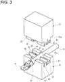
- Fig. 3 is a perspective view showing a state in which a coated electric wire 15 is set in the pair of molds 51 and 61 shown in Fig. 1 .
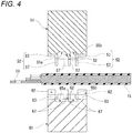
- Fig. 4 is a cross-sectional view taken along an extending direction of the coated electric wire 15 in the pair of molds 51 and 61 shown in Fig. 1 .
- the pair of molds 51 and 61 are molds for injection-molding a seal portion 25 and a burr cut portion 27 that are waterproof members surrounding a part of the coated electric wire 15 in the extending direction.
- the coated electric wire 15 according to the present embodiment is a coated electric wire applied to a so-called over-molded connector in which a part of a terminal 19 connected to a conductor 17 at an end portion and the end portion are covered with an insulating housing 13 (see Fig. 10B ).
- the seal portion 25 and the burr cut portion 27 are formed by injection molding using an insulating elastic member such as a thermoplastic elastomer.
- the mold 51 (first mold) is a movable mold having a first mold division surface 51a
- the mold 61 (second mold) is a fixed mold having a second mold division surface 61a
- the first mold division surface 51a according to the embodiment is formed with a molding portion 55a and a molding portion 55b for injection molding the seal portion 25 and the burr cut portion 27, and four electric wire mold clamping portions 52 that is configured to, when the coated electric wire 15 is set between the molds 51, 61 and the mold 51 is attached to the mold 61, hold/ sandwich an outer peripheral surface of the coated electric wire 15 at both sides of each of the molding portions 55a and 55b in the extending direction of the coated electric wire 15.
- Each of the electric wire mold clamping portions 52 includes a convex portion 53 (first convex portion) having a semi-cylindrical concave surface 54 (first semi-cylindrical concave surface) that comes into contact with an outer peripheral surface of the coated electric wire 15, and side walls 57 erected on an end of the convex portion 53 in the extending direction of the coated electric wire 15.
- the end of the convex portion 53 is the one which is connected/adjacent to the molding portions 55a, 55b.
- the semi-cylindrical concave surface 54 of the convex portion 53 is a concave surface that has an arc cross section having a radius of curvature substantially the same as a radius of curvature of the coated electric wire 15 and having a central angle less than 180 degrees.
- Two electric wire clamping portions 52 positioned in the middle of the mold 51 in the extending direction have an integrated structure in which the semi-cylindrical concave surfaces 54 of respective convex portions 53 are continuous with the two electric wire clamping portions 52.
- the second mold division surface 61a is formed with a molding portion 65a and a molding portion 65b (second molding portion) for injection molding the seal portion 25 and the burr cut portion 27, and four electric wire mold clamping portions 62 configured to, when the coated electric wire 15 is set between the molds 51, 61 and the mold 51 is attached to the mold 61, hold/sandwich the outer peripheral surface of the coated electric wire 15 at both sides of each of the molding portions 65a and 65b in the extending direction of the coated electric wire 15.
- Each of the electric wire mold clamping portions 62 includes a concave portion 63 to face the convex portion 53 and a side wall entering groove 67 to face the side wall 57.
- the concave portion 63 has a U-shaped cross section and includes a semi-cylindrical concave surface 64 (second semi-cylindrical concave surface) that comes into contact with the outer peripheral surface of the coated electric wire 15.
- the side wall entering groove 67 is formed by cutting out a part of the molding portion 65a or the molding portion 65b, and configured such that the side wall 57 can be inserted into the side wall entering groove 67.
- the semi-cylindrical concave surface 64 of the concave portion 63 is formed continuously with a pair of parallel surfaces at opening end sides of the concave portion 63.
- the semi-cylindrical concave surface 64 is a concave surface having an arc cross section whose radius of curvature is substantially the same as the radius of curvature of the coated electric wire 15.
- the radius of curvature of the semi-cylindrical concave surface 64 is slightly smaller than the radius of curvature of the coated electric wire 15, as shown in Fig.
- a coating of the coated electric wire 15 accommodated in the concave portion 63 can be elastically deformed and pressed, and a gap between the coated electric wire 15 and an adjacent electric wire mold clamping portion 62 can be eliminated.
- Two electric wire clamping portions 62 positioned in the middle of the mold 61 in the extending direction have an integrated structure in which the semi-cylindrical concave surfaces 64 of respective concave portions 63 are continuous with the two electric wire clamping portions 62.
- Fig. 5A is a side view showing the pair of molds 51 and 61 during a course of mold clamping
- Fig. 5B is a cross-sectional view taken along the extending direction of the coated electric wire 15 in Fig. 5A
- Fig. 6A is a cross-sectional view taken along a line A-A in Fig. 5A
- Fig. 6B is a cross-sectional view taken along a line B-B in Fig. 5A .
- FIG. 7A is a side view showing the pair of molds 51 and 61 in a mold clamped state
- Fig. 7B is a cross-sectional view taken along the extending direction of the coated electric wire 15 in Fig. 7A
- Fig. 8A is a cross-sectional view taken along a line C-C in Fig. 7A
- Fig. 8B is a cross-sectional view taken along a line D-D in Fig. 7A
- Fig. 9 is a perspective view showing a mold open state of the pair of molds 51 and 61 after the seal portion 25 and the burr cut portion 27 are molded at a part of the coated electric wire 15.
- the coated electric wire 15 is disposed between the mold 51 and the mold 61, and a part of the coated electric wire 15 in the extending direction is accommodated in the concave portion 63 of the electric wire mold clamping portion 62 formed on the second mold division surface 61a of the mold 61.
- the mold 51 is moved toward the mold 61.
- the molding portions 55a and 55b and the electric wire mold clamping portion 52 that are formed on the first mold division surface 51a respectively face the molding portions 65a and 65b and the electric wire mold clamping portion 62 that are formed on the second mold division surface 61a.
- the coated electric wire 15 accommodated in the concave portion 63 having a U-shaped cross section and including the semi-cylindrical concave surface 64 in the electric wire mold clamping portion 62 is pressed and biased in a clamping direction (a first direction) by the convex portion 53 including the semi-cylindrical concave surface 54.
- the clamping direction is a direction in which the mold 51 is attached to the mold 61. That is, the coated electric wire 15 accommodated in the concave portion 63 having a depth larger than a diameter of the coated electric wire 15 is interposed between the semi-cylindrical concave surface 64 of the concave portion 63 and the semi-cylindrical concave surface 54 of the convex portion 53. Therefore, the coated electric wire 15 is easily disposed in the electric wire mold clamping portion 62, and is less likely to be caught at the time of mold clamping.
- side walls 57 respectively erected on the ends of the convex portions 53, the ends being adjacent to/connected to the molding portions 55a, 55b, in the extending direction of the coated electric wire 15 are inserted into the side wall entering grooves 67 each formed by cutting out a part of the molding portion 65a or the molding portion 65b, so that gaps S generated among the coated electric wire 15, the concave portion 63 in the electric wire mold clamping portion 62, and the convex portion 53 are prevented from communicating with the molding portions 55a and 65a or communicating with the molding portions 55b and 65b.
- the convex portion 53 presses and biases the coated electric wire 15, the coating of the coated electric wire 15 is less likely to be damaged. Then, after the molten resin that entered the molding spaces is solidified, as shown in Fig. 9 , the mold 51 is retracted and separated from the mold 61, and then the coated electric wire 15 is taken out from the mold 61.
- Fig. 10A is a perspective view showing the coated electric wire 15 on which the seal portion 25 and the burr cut portion 27 are formed at a part of the coated electric wire 15 in the extending direction
- Fig. 10B is a perspective view showing a connector 11 in which the housing 13 is formed on the coated electric wire 15 in Fig. 10A by secondary molding
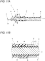
- Fig. 11A is a longitudinal cross-sectional view showing the connector 11 shown in Fig. 10B
- Fig. 11B is an enlarged view showing main parts of the seal portion 25 and the burr cut portion 27.
- the seal portion 25 and the burr cut portion 27 are formed on the outer peripheral surface of the coated electric wire 15, which was taken out from the mold 16, such that the seal portion 25 and the burr cut portion 27 partially surround the coated electric wire 15 in the extending direction.
- the seal portion 25 includes a cylindrical portion 26 that covers an outer peripheral surface of the coating of the coated electric wire 15, and bulging portions 30 that protrude from two end portions of the cylindrical portion 26 toward an axial direction of the cylindrical portion 26.
- the bulging portion 30 is a portion where the molten resin flows into a molding space defined by a part of the side wall 57 inserted into the side wall entering groove 67 and a part of the molding portion 65a and the molten resin is solidified.
- the bulging portion 30 is unique to the seal portion 25 that is injection-molded using the pair of molds 51 and 61 according to the embodiment. Similar to the seal portion 25, the burr cut portion 27 also includes a cylindrical portion 28 that covers the outer peripheral surface of the coating of the coated electric wire 15, and bulging portions 30 that protrude from two end portions of the cylindrical portion 28 toward the axial direction of the cylindrical portion 28.
- the coated electric wire 15 on which the seal portion 25 and the burr cut portion 27 surrounding a part of the coated electric wire 15 in the extending direction are primarily molded is applied to the connector 11 in which the seal portion 25 and a part of the terminal 19 at an end portion are secondarily molded as the housing 13 using an insulating resin such as a thermoplastic resin.
- the burr cut portion 27 is formed continuously with one end portion of the housing 13.
- the terminal 19 is conductively connected to the conductor 17 at an end portion of the coated electric wire 15.
- a connection portion 29 between the terminal 19 and the conductor 17 is covered with the housing 13.
- An electrical contact portion 23 of the terminal which is at an opposite side of the connection portion 29 protrudes to the outside of the housing 13.
- the housing 13 is formed of an insulating resin (for example, PBT) having higher rigidity than an elastic material used for the seal portion 25 and the burr cut portion 27.
- the housing 13 integrally covers the seal portion 25 at an end portion of the coated electric wire 15 and the connection portion 29 of the terminal 19.
- the housing 13 covers the entirety of the seal portion 25.
- the housing 13 has a flange portion 31 that protrudes outward in a radial direction at a substantially central portion of the housing 13 in a direction along the coated electric wire 15.
- the flange portion 31 serves as a contact portion to be brought into contact with an attachment portion having an attachment hole.
- a peripheral groove 33 is formed on an outer periphery of the housing 13 further on a terminal side relative to the flange portion 31.
- An annular elastic seal member (not shown) is mounted in the peripheral groove 33.
- the seal portion 25 and the burr cut portion 27 that are primarily molded are separated from each other by a predetermined distance.
- the seal portion 25 and the burr cut portion 27 are annular bodies having different outer diameters and are in close contact with the outer peripheral surface of the coating 21.
- an outer diameter of the burr cut portion 27 is formed to be larger than an outer diameter of the seal portion 25.
- the burr cut portion 27 serves as contact portion against burrs and cuttings formed in a mold, and also functions as a second seal portion that seals the housing 13 and the coating 21 in a watertight manner.
- the burr cut portion 27 serves as a contact portion for this purpose. Burrs and cuttings form a plurality of sharp tip shaped portions arranged like mountains that may contact/sandwich the coated electric wire 15. Therefore, in a case where the housing 13 is directly formed on the outer peripheral surface of the coated electric wire 15, the coating 21 may be damaged when the coated electric wire 15 is disposed in the mold. In the connector 11, since burrs and cuttings provided in the mold used in the secondary molding come into contact with an outer periphery of the burr cut portion 27 formed by primary molding, the coating of the coated electric wire 15 is not damaged due to the burrs and cuttings.
- Fig. 12 is a perspective view showing a mold open state of a pair of molds 51A and 61A used in a molding method of a waterproof member according to another embodiment of the present invention.
- Fig. 13 is a perspective view showing first and second mold division surfaces 51a and 61a of the pair of molds 51A and 61A shown in Fig. 12 .
- Figs. 14A and 14B are cross-sectional views taken along the extending direction of the coated electric wire 15 in the pair of molds 51A and 61A shown in Fig. 12 , in which Fig. 14A shows a mold open state and Fig. 14B shows a mold clamped state. Components the same as those of the molds 51 and 61 according to the embodiment are denoted by the same reference numerals, and a description thereof will be omitted.
- an electric wire deformation preventing portion 59 configured to restrict bending of the coated electric wire 15 along the extending direction is provided in a protruding manner on an inner surface of the molding portion 55b in the mold 51A according to the another embodiment.
- an electric wire deformation preventing portion 69 configured to restrict bending of the coated electric wire 15 along the extending direction is provided in a protruding manner on an inner surface of the molding portion 65b in the mold 61A.
- the coated electric wire 15 is disposed between the mold 51A and the mold 61A as shown in Fig. 14A , and then the mold 51A and the mold 61A are clamped as shown in Fig. 14B .
- the molding portion 55b and the molding portion 65b that mold the burr cut portion 27A according to the another embodiment are made relatively longer along the extending direction of the coated electric wire 15 than the molding portion 55b and the molding portion 65b that mold the burr cut portion 27 according to the embodiment. Therefore, the coated electric wire 15 according to the another embodiment is likely to bend along the extending direction in the molding space defined by the molding portions 55b and 65b.
- the electric wire deformation preventing portions 59 and 69 are provided in a protruding manner respectively on inner surfaces of the molding portions 55b and 65b, as shown in Fig. 14B , it is possible to restrict the coated electric wire 15 from bending along the extending direction in the molding space defined by the molding portions 55b and 65b. Therefore, it is possible to prevent the occurrence of a portion of the burr cut portion 27A where a thickness of the burr cut portion 27A is reduced due to bending of the coated electric wire 15 along the extending direction in the molding space (i.e., the occurrence of short circuit), and prevent the occurrence of burrs caused by leakage of the molten resin from the gap generated in the electric wire clamping portions 52, 62.
- Fig. 15A is a perspective view and Fig. 15B is a side view showing the coated electric wire 15 on which the seal portion 25 and the burr cut portion 27 are formed at a part of the coated electric wire 15 in the extending direction according to the another embodiment of the present invention.
- the seal portion 25 and the burr cut portion 27A that surround a part of the coated electric wire 15 in the extending direction are formed on the outer peripheral surface of the coated electric wire 15 that was taken out from the molds 51A and 61A.
- the burr cut portion 27A includes a pair of concave portions 37 and 39 on an outer peripheral surface of a cylindrical portion 28A that covers an outer peripheral surface of the coating of the coated electric wire 15.
- the concave portions 37 and 39 are portions formed by the electric wire deformation preventing portions 59 and 69 provided in a protruding manner respectively on the inner surfaces of the molding portions 55b and 65b, and the concave portions 37 and 39 are unique to the burr cut portion 27A injection-molded by the pair of molds 51A and 61A according to the another embodiment.
- Fig. 16 is a perspective view showing a mold open state of a pair of molds 71 and 81 used in a molding method of a waterproof member according to a yet another embodiment of the present invention.
- Fig. 17 is a perspective view showing first and second mold division surfaces 71a and 81a of the pair of molds 71 and 81 shown in Fig. 16 .
- Fig. 18 is a cross-sectional view taken along the extending direction of the coated electric wire 15 in the pair of molds 71 and 81 shown in Fig. 16 .
- Fig. 19 is a cross-sectional view showing a mold clamped state of the pair of molds 71 and 81 shown in Fig. 18 .
- Components the same as those of the molds 51 and 61 according to the embodiment are denoted by the same reference numerals, and a description thereof will be omitted.
- the mold 71 according to the yet another embodiment is a movable mold having the first mold division surface 71a
- the mold 81 is a fixed mold having the second mold division surface 81a.
- the first mold division surface 71a according to the yet another embodiment is formed with a molding portion 75a and a molding portion 75b for injection-molding a seal portion 25B and a burr cut portion 27B, and electric wire mold clamping portions 72 and electric wire mold clamping portions 76 configured to sandwich an outer peripheral surface of the coated electric wire 15 at both sides of each of the molding portions 75a and 75b in the extending direction of the coated electric wire 15.
- the second mold division surface 81a is formed with a molding portion 85a and a molding portion 85b for injection-molding the seal portion 25B and the burr cut portion 27B, and electric wire mold clamping portions 82 and electric wire mold clamping portions 86 configured to sandwich the outer peripheral surface of the coated electric wire 15 at both sides of each of the molding portions 85a and 85b in the extending direction of the coated electric wire 15.
- Each of the electric wire mold clamping portions 76 of the first mold division surface 71a includes a convex portion 79 (first convex portion) having a semi-cylindrical concave surface 70 that comes into contact with an outer peripheral surface of the coated electric wire 15, and side walls 78 erected on ends of the convex portions 79 in the extending direction of the coated electric wire 15, the ends being connected to the molding portion 75a or the molding portion 75b.
- the semi-cylindrical concave surface 70 of the convex portion 79 is a concave surface that has an arc cross section having a radius of curvature substantially the same as a radius of curvature of the coated electric wire 15 and having a central angle less than 180 degrees.
- Two electric wire clamping portions 76 positioned in the middle of the mold 71 in the extending direction have an integrated structure in which the semi-cylindrical concave surfaces 70 of respective convex portions 79 are continuous with the two electric wire clamping portions 76.
- Each of the electric wire mold clamping portions 86 of the second mold division surface 81a includes a concave portion 89 facing the convex portion 79, and a side wall entering groove 88 facing the side wall 78.
- the concave portion 89 (first concave portion) has a U-shaped cross section and includes a semi-cylindrical concave surface 90 that comes into contact with the outer peripheral surface of the coated electric wire 15.
- the side wall entering groove 88 is formed by cutting out a part of the molding portion 85a or the molding portion 85b, and the side wall 78 can be inserted into the side wall entering groove 88.
- the semi-cylindrical concave surface 90 of the concave portion 89 is formed continuously with a pair of parallel surfaces at opening end sides of the concave portion 89.
- the semi-cylindrical concave surface 90 is a concave surface having an arc cross section whose radius of curvature is substantially the same as the radius of curvature of the coated electric wire 15.
- Two electric wire clamping portions 86 positioned in the middle of the mold 81 in the extending direction have an integrated structure in which the semi-cylindrical concave surfaces 90 of respective concave portions 89 are continuous with the two electric wire clamping portions 86.
- Each of the electric wire mold clamping portions 82 of the second mold division surface 81a includes a convex portion 83 (second convex portion) having a semi-cylindrical concave surface 84 that comes into contact with an outer peripheral surface of the coated electric wire 15, and side walls 87 erected on ends of the convex portions 83 in the extending direction of the coated electric wire 15, the ends being connected to the molding portion 85a or the molding portion 85b.
- the semi-cylindrical concave surface 84 of the convex portion 83 is a concave surface that has an arc cross section having a radius of curvature substantially the same as a radius of curvature of the coated electric wire 15 and having a central angle less than 180 degrees.
- Each of the electric wire mold clamping portions 72 of the first mold division surface 71a includes a concave portion 73 (second concave portion) facing the convex portion 83, and a side wall entering groove 77 facing the side wall 87.
- the concave portion 73 has a U-shaped cross section and includes a semi-cylindrical concave surface 74 that comes into contact with the outer peripheral surface of the coated electric wire 15.
- the side wall entering groove 77 is formed by cutting out a part of the molding portion 75a or the molding portion 75b, and the side wall 87 can be inserted into the side wall entering groove 77.
- the semi-cylindrical concave surface 74 of the concave portion 73 is formed continuously with a pair of parallel surfaces at opening end sides of the concave portion 73.
- the semi-cylindrical concave surface 74 is a concave surface having an arc cross section whose radius of curvature is substantially the same as the radius of curvature of the coated electric wire 15.
- each convex portion 79 and each concave portion 73 are formed on both sides (first and second sides) of the molding portion 75a or the molding portion 75b on the first mold division surface 71a in the extending direction
- each concave portion 89 and each convex portion 83 are formed on two sides (first and second sides) of the molding portion 85a or the molding portion 85b on the second mold division surface 81a in the extending direction.
- the coated electric wire 15 is interposed between the electric wire mold clamping portions 72 and 82 and between the electric wire mold clamping portions 76 and 86 at both sides of the molding portions 75a, 85a or the molding portions 75b, 85b, and the coated electric wire 15 is pressed and biased in opposite directions at the two sides of the molding portions 75a, 85a or the molding portions 75b, 85b.
- the coated electric wire 15 is pressed toward the first direction at the first sides of the molding portions 75a, 75b, 85a, 85b and toward a second direction opposite to the first direction at the second sides of the molding portions 75a, 75b, 85a, 85b, the second sides being opposite to the first sides in the extending direction of the coated electric wire 15.
- the coated electric wire 15 is less likely to bend along the extending direction in a molding space defined by the molding portions 75a, 85a or the molding portions 75b, 85b.
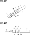
- Fig. 20A is a perspective view and Fig. 20B is a side view showing the coated electric wire on which the seal portion 25B and the burr cut portion 27B are formed at a part of the coated electric wire 15 in the extending direction according to the yet another embodiment of the present invention.
- the seal portion 25B and the burr cut portion 27B that surround a part of the coated electric wire 15 in the extending direction are formed on the outer peripheral surface of the coated electric wire 15 that was taken out from the molds 71 and 81.
- the seal portion 25B includes the cylindrical portion 26 that covers an outer peripheral surface of the coating of the coated electric wire 15, and bulging portions 30B that protrude from two end portions of the cylindrical portion 26 toward an axial direction.
- the bulging portion 30B is a portion where the molten resin flows into a molding space defined by a part of the side walls 87 and 78 inserted into the side wall entering grooves 77 and 88 and a part of the molding portions 75a, 75b, 85a, and 85b and the molten resin is solidified.
- the bulging portion 30B is unique to the seal portion 25B that is injection-molded using the pair of molds 71 and 81 according to the yet another embodiment.
- a molding method of a waterproof member is provided.
- the waterproof member (for example, the seal portion 25, the burr cut portion 27) is molded by a pair of molds (51, 61) and is configured to surround a part of a coated electric wire (15) in an extending direction of the coated electric wire (15) in which the coated electric wire (15) extends.
- the pair of molds (51, 61) includes a first mold (51) and a second mold (61) having a first mold division surface (51a) and a second mold division surface (61a), respectively.
- the first mold division surface (51a) includes a first molding portion (55a, 55b) and a first electric wire mold clamping portion (52) and the second mold division surface (61a) includes a second molding portion (65a, 65b) and a second electric wire mold clamping portion (62).
- the first and second molding portions (55a, 55b, 65a, 65b) are configured to mold the waterproof member (for example, the seal portion 25, the burr cut portion 27) when the waterproof member is injection-molded.
- the first and second electric wire mold clamping portions (52, 62) are configured to, when the first mold (51) is attached to the second mold (61) with the coated electric wire (15) being disposed between the first and second molds (51, 61), sandwich the coated electric wire (15) at both sides of each of the first and second molding portions (55a, 55b, 65a, 65b) in the extending direction of the coated electric wire (15).
- the first electric wire mold clamping portion (52) includes a first convex portion (53) having a first semi-cylindrical concave surface (54) configured to contact an outer peripheral surface of the coated electric wire (15) and a side wall (57) erected on an end of the first convex portion (53) in the extending direction of the coated electric wire (15), the end being connected to the first molding portion (55a, 55b).
- the second electric wire mold clamping portion (62) includes a first concave portion (63) including a second semi-cylindrical concave surface (64) configured to contact the outer peripheral surface of the coated electric wire (15) while being opposed to the first convex portion (53), the first concave portion (63) having a U-shaped cross section.
- the second molding portion (65a, 65b) includes a side wall entering groove (67) formed by cutting out a part of the second molding portion (65a, 65b), the side wall entering groove (67) being configured such that, when the first mold (51) is attached to the second mold (61), the side wall (57) enters the side wall entering groove (67).
- the method includes molding the waterproof member (25, 27) accommodated in the first concave portion (63) with the waterproof member (25, 27) being pressed by the first convex portion (53) toward a first direction in which the first mold (51) is attached to the second mold (61).
- the pair of molds are aligned so as to sandwich the coated electric wire in parallel by the electric wire mold clamping portions respectively formed at both sides of each of the molding portions in the extending direction of the coated electric wire, and the pair of molds are clamped, a molding portion for injection-molding the waterproof member is defined between the pair of molds. Then, the coated electric wire accommodated in the concave portion having a U-shaped cross section and including the semi-cylindrical concave surface in the electric wire mold clamping portion is pressed and biased in a clamping direction by the convex portion including the semi-cylindrical concave surface.
- the coated electric wire is accommodated in the concave portion having a depth larger than a diameter of the coated electric wire and the coated electric wire is interposed between the semi-cylindrical concave surface of the concave portion and the semi-cylindrical concave surface of the convex portion. Therefore, the coated electric wire is easily disposed in the electric wire mold clamping portion and is less likely to be caught at the time of mold clamping.
- the side wall erected on an end of the convex portion in the extending direction of the coated electric wire, the end being connected to the molding portion is inserted into the side wall entering groove formed by cutting out a part of the molding portions, so that a gap generated among the coated electric wire, the concave portion and the convex portion in the electric wire mold clamping portion is prevented from communicating with the molding portions. Therefore, when the molten resin in the molding portions is injected out, the molten resin that entered the molding portions does not leak out from the gap formed among the concave portion, the convex portion, and the coated electric wire.
- An electric wire deformation preventing portion (59, 69) may be provided in a protruding manner on an inner surface of at least one of the first and second molding portions (55b, 65b), the electric wire deformation preventing portion (59, 69) being configured to restrict bending of the coated electric wire (15) in the first and second molding portions (55b, 65b).
- the first mold division surface (71a) may include the first convex portion (79) and a second concave portion (73) including a third semi-cylindrical concave surface configured to contact the outer peripheral surface of the coated electric wire (15) while being opposed to a second convex portion (83), the second concave portion (73) having a U-shaped cross section, the first convex portion (79) and the second concave portion (73) being provided on first and second sides of the first molding portion (75a, 75b) in the extending direction of the coated electric wire (15).
- the second mold division surface (81a) may include the first concave portion (89) and the second convex portion (83) having a fourth semi-cylindrical concave surface configured to contact the outer peripheral surface of the coated electric wire (15), the first concave portion (89) and the second convex portion (83) being provided on first and second sides of the second molding portion (85a, 85b) in the extending direction of the coated electric wire (15).
- the waterproof member (for example, the seal portion 25B, the burr cut portion 27B) may be molded while the coated electric wire (15) is pressed toward the first direction at the first sides of the first and second molding portions (75a, 75b, 85a, 85b) and toward a second direction opposite to the first direction at the second sides of the first and second molding portions (75a, 75b, 85a, 85b), the second sides being opposite to the first sides in the extending direction of the coated electric wire (15).
- the coated electric wire interposed between the electric wire clamping portions at both (two) sides of each of the molding portions is pressed and biased in opposite clamping directions at the two sides of each of the molding portions.
- the coated electric wire is less likely to bend along the extending direction in the molding portions. Therefore, it is possible to prevent the occurrence of a portion of the waterproof member where a thickness of waterproof member is reduced due to bending of the coated electric wire along the extending direction in the molding portion (i.e., occurrence of short circuit), and prevent the occurrence of burrs caused by leakage of the molten resin from the gap generated in the electric wire clamping portion.
Landscapes
- Engineering & Computer Science (AREA)
- Manufacturing & Machinery (AREA)
- Mechanical Engineering (AREA)
- Chemical & Material Sciences (AREA)
- Dispersion Chemistry (AREA)
- Moulds For Moulding Plastics Or The Like (AREA)
- Injection Moulding Of Plastics Or The Like (AREA)
- Connector Housings Or Holding Contact Members (AREA)
- Manufacturing Of Electrical Connectors (AREA)
Abstract
Description
- The present invention relates to a molding method of a waterproof member configured to cover a coating of a coated electric wire.
- A related art waterproof structure includes a waterproof member for ensuring waterproofness between an attachment hole of an attachment portion and a coated electric wire inserted through the attachment hole. A connector having such waterproof structure in the related art includes a primary molded portion (waterproof member) formed of an insulating elastic material that covers an exposed portion of a conductor of a wire harness (electric wire) including a conductor and a coating portion, and a secondary molded portion formed of an insulating resin that covers almost the entirety of the primary molded portion and a part of a terminal (see, for example,
JP2013-41677A - In the waterproof member, since a portion of the waterproof member covering the coating of the electric wire has a cylindrical shape, it is necessary to fit upper and lower molds each having a semicircular cavity (molding portion) at the time of injection molding. Since the electric wire has a large variation in diameter and the coating thereof is often soft, it is necessary to compress and mold the electric wire using the upper and lower molds when the waterproof member is primarily molded. However, when the diameter of the electric wire is increased, a cross-sectional area of the electric wire is increased with respect to a cross-sectional area of a clamping portion of the upper and lower molds. As a result, the coating may be interposed in a gap between the upper and lower molds, the coating may be damaged or broke, and an insulation property or a waterproof property may be deteriorated. In addition, when the diameter of the electric wire is reduced, the coating is deformed by an injection pressure at the time of injection molding, a gap may be formed between the upper and lower molds and burrs may be generated, which may cause poor external appearance.
- Illustrative aspects of the present invention provide a molding method of a waterproof member configured to prevent deterioration in waterproof function due to poor external appearance of a coated electric wire, and damage or breakage of a coating of the coated electric wire.
- According to an illustrative aspect of the present invention, a molding method of a waterproof member is provided. The waterproof member is molded by a pair of molds. The waterproof member is configured to surround a part of a coated electric wire in an extending direction of the coated electric wire in which the coated electric wire extends. The pair of molds includes a first mold and a second mold. The first mold has a first mold division surface. The second mold has a second mold division surface. The first mold division surface includes a first molding portion and a first electric wire mold clamping portion. The second mold division surface includes a second molding portion and a second electric wire mold clamping portion. The first and second molding portions are configured to mold the waterproof member when the waterproof member is injection-molded. The first and second electric wire mold clamping portions are configured to, when the first mold is attached to the second mold with the coated electric wire being disposed between the first and second molds, sandwich the coated electric wire at both sides of each of the first and second molding portions in the extending direction of the coated electric wire. The first electric wire mold clamping portion includes a first convex portion having a first semi-cylindrical concave surface configured to contact an outer peripheral surface of the coated electric wire and a side wall erected on an end of the first convex portion in the extending direction of the coated electric wire, the end being connected to the first molding portion. The second electric wire mold clamping portion includes a first concave portion including a second semi-cylindrical concave surface configured to contact the outer peripheral surface of the coated electric wire while being opposed to the first convex portion, the first concave portion having a U-shaped cross section. The second molding portion includes a side wall entering groove formed by cutting out a part of the second molding portion, the side wall entering groove being configured such that, when the first mold is attached to the second mold, the side wall enters the side wall entering groove. The method includes molding the waterproof member accommodated in the first concave portion with the waterproof member being pressed by the first convex portion toward a first direction in which the first mold is attached to the second mold.
- Other aspects and advantages of the invention will be apparent from the following description, the drawings and the claims.
-
-
Fig. 1 is a perspective view showing an opened state of a pair of molds used in a molding method of a waterproof member according to an embodiment of the present invention; -
Figs. 2A and 2B are perspective views showing first and second mold division surfaces of the pair of molds shown inFig. 1 ; -
Fig. 3 is a perspective view showing a state in which a coated electric wire is set in the pair of molds shown inFig. 1 ; -
Fig. 4 is a cross-sectional view taken along an extending direction of the coated electric wire in the pair of molds shown inFig. 1 ; -
Fig. 5A is a side view showing the pair of molds during a course of mold clamping, andFig. 5B is a cross-sectional view taken along the extending direction of the coated electric wire inFig. 5A ; -
Fig. 6A is a cross-sectional view taken along a line A-A inFig. 5A , andFig. 6B is a cross-sectional view taken along a line B-B inFig. 5A ; -
Fig. 7A is a side view showing the pair of molds in a mold clamped state, andFig. 7B is a cross-sectional view taken along the extending direction of the coated electric wire inFig. 7A ; -
Fig. 8A is a cross-sectional view taken along a line C-C inFig. 7A , andFig. 8B is a cross-sectional view taken along a line D-D inFig. 7A ; -
Fig. 9 is a perspective view showing the opened state of the pair of molds after a waterproof member is molded at a part of the coated electric wire; -
Fig. 10A is a perspective view showing the coated electric wire on which the waterproof member is formed at a part of the coated electric wire in the extending direction, andFig. 10B is a perspective view showing a connector in which a housing is formed on the coated electric wire inFig. 10A by secondary molding; -
Fig. 11A is a longitudinal sectional view showing the connector shown inFig. 10B , andFig. 11B is an enlarged view showing a main part of the waterproof member; -
Fig. 12 is a perspective view showing an opened state of a pair of molds used in a molding method of a waterproof member according to another embodiment of the present invention; -
Fig. 13 is a perspective view showing first and second mold division surfaces of the pair of molds shown inFig. 12 ; -
Figs. 14A and 14B are cross-sectional views taken along the extending direction of the coated electric wire in the pair of molds shown inFig. 12 , in whichFig. 14A shows the opened state andFig. 14B shows a mold clamped state; -
Fig. 15A is a perspective view andFig. 15B is a side view showing the coated electric wire on which the waterproof member is formed at a part of the coated electric wire in the extending direction according to the another embodiment of the present invention; -
Fig. 16 is a perspective view showing an opened state of a pair of molds used in a molding method of a waterproof member according to a yet another embodiment of the present invention; -
Fig. 17 is a perspective view showing first and second mold division surfaces of the pair of molds shown inFig. 16 ; -
Fig. 18 is a cross-sectional view taken along the extending direction of the coated electric wire in the pair of molds shown inFig. 16 ; -
Fig. 19 is a cross-sectional view showing a mold clamped state of the pair of molds shown inFig. 18 ; and -
Fig. 20A is a perspective view andFig. 20B is a side view showing the coated electric wire on which the waterproof member is formed at a part of the coated electric wire in the extending direction according to the yet another embodiment of the present invention. - Hereinafter, embodiments according to the present invention will be described with reference to the drawings.
Fig. 1 is a perspective view showing an opened state/ a mold open state of a pair ofmolds Figs. 2A and 2B are perspective views showing first and second mold division surfaces 51a and 61a of the pair ofmolds Fig. 1 .Fig. 3 is a perspective view showing a state in which a coatedelectric wire 15 is set in the pair ofmolds Fig. 1 .Fig. 4 is a cross-sectional view taken along an extending direction of the coatedelectric wire 15 in the pair ofmolds Fig. 1 . - The pair of
molds seal portion 25 and aburr cut portion 27 that are waterproof members surrounding a part of the coatedelectric wire 15 in the extending direction. The coatedelectric wire 15 according to the present embodiment is a coated electric wire applied to a so-called over-molded connector in which a part of a terminal 19 connected to aconductor 17 at an end portion and the end portion are covered with an insulating housing 13 (seeFig. 10B ). Theseal portion 25 and the burr cutportion 27 are formed by injection molding using an insulating elastic member such as a thermoplastic elastomer. - As shown in
Figs. 1 to 4 , the mold 51 (first mold) according to the embodiment is a movable mold having a firstmold division surface 51a, and the mold 61 (second mold) is a fixed mold having a secondmold division surface 61a. The firstmold division surface 51a according to the embodiment is formed with amolding portion 55a and amolding portion 55b for injection molding theseal portion 25 and the burr cutportion 27, and four electric wiremold clamping portions 52 that is configured to, when the coatedelectric wire 15 is set between themolds mold 51 is attached to themold 61, hold/ sandwich an outer peripheral surface of the coatedelectric wire 15 at both sides of each of themolding portions electric wire 15. - Each of the electric wire
mold clamping portions 52 includes a convex portion 53 (first convex portion) having a semi-cylindrical concave surface 54 (first semi-cylindrical concave surface) that comes into contact with an outer peripheral surface of the coatedelectric wire 15, andside walls 57 erected on an end of theconvex portion 53 in the extending direction of the coatedelectric wire 15. The end of theconvex portion 53 is the one which is connected/adjacent to themolding portions concave surface 54 of theconvex portion 53 is a concave surface that has an arc cross section having a radius of curvature substantially the same as a radius of curvature of the coatedelectric wire 15 and having a central angle less than 180 degrees. Two electricwire clamping portions 52 positioned in the middle of themold 51 in the extending direction have an integrated structure in which the semi-cylindricalconcave surfaces 54 of respectiveconvex portions 53 are continuous with the two electricwire clamping portions 52. - The second
mold division surface 61a according to the embodiment is formed with amolding portion 65a and amolding portion 65b (second molding portion) for injection molding theseal portion 25 and the burr cutportion 27, and four electric wiremold clamping portions 62 configured to, when the coatedelectric wire 15 is set between themolds mold 51 is attached to themold 61, hold/sandwich the outer peripheral surface of the coatedelectric wire 15 at both sides of each of themolding portions electric wire 15. - Each of the electric wire
mold clamping portions 62 includes aconcave portion 63 to face theconvex portion 53 and a sidewall entering groove 67 to face theside wall 57. Theconcave portion 63 has a U-shaped cross section and includes a semi-cylindrical concave surface 64 (second semi-cylindrical concave surface) that comes into contact with the outer peripheral surface of the coatedelectric wire 15. The sidewall entering groove 67 is formed by cutting out a part of themolding portion 65a or themolding portion 65b, and configured such that theside wall 57 can be inserted into the sidewall entering groove 67. The semi-cylindricalconcave surface 64 of theconcave portion 63 is formed continuously with a pair of parallel surfaces at opening end sides of theconcave portion 63. The semi-cylindricalconcave surface 64 is a concave surface having an arc cross section whose radius of curvature is substantially the same as the radius of curvature of the coatedelectric wire 15. When the radius of curvature of the semi-cylindricalconcave surface 64 is slightly smaller than the radius of curvature of the coatedelectric wire 15, as shown inFig. 3 , a coating of the coatedelectric wire 15 accommodated in theconcave portion 63 can be elastically deformed and pressed, and a gap between the coatedelectric wire 15 and an adjacent electric wiremold clamping portion 62 can be eliminated. Two electricwire clamping portions 62 positioned in the middle of themold 61 in the extending direction have an integrated structure in which the semi-cylindricalconcave surfaces 64 of respectiveconcave portions 63 are continuous with the two electricwire clamping portions 62. - Next, a molding method of a waterproof member for injection molding the
seal portion 25 and the burr cutportion 27 surrounding a part of the coatedelectric wire 15 in the extending direction by using the pair ofmolds Fig. 5A is a side view showing the pair ofmolds Fig. 5B is a cross-sectional view taken along the extending direction of the coatedelectric wire 15 inFig. 5A .Fig. 6A is a cross-sectional view taken along a line A-A inFig. 5A , andFig. 6B is a cross-sectional view taken along a line B-B inFig. 5A .Fig. 7A is a side view showing the pair ofmolds Fig. 7B is a cross-sectional view taken along the extending direction of the coatedelectric wire 15 inFig. 7A .Fig. 8A is a cross-sectional view taken along a line C-C inFig. 7A , andFig. 8B is a cross-sectional view taken along a line D-D inFig. 7A .Fig. 9 is a perspective view showing a mold open state of the pair ofmolds seal portion 25 and the burr cutportion 27 are molded at a part of the coatedelectric wire 15. - First, as shown in
Figs. 3 and4 , the coatedelectric wire 15 is disposed between themold 51 and themold 61, and a part of the coatedelectric wire 15 in the extending direction is accommodated in theconcave portion 63 of the electric wiremold clamping portion 62 formed on the secondmold division surface 61a of themold 61. - Next, as shown in
Figs. 5A, 5B ,6A, and 6B , themold 51 is moved toward themold 61. When themold 51 is moved toward themold 61, themolding portions mold clamping portion 52 that are formed on the firstmold division surface 51a respectively face themolding portions mold clamping portion 62 that are formed on the secondmold division surface 61a. - Then, as shown in
Figs. 7A, 7B ,8A, and 8B , when the pair ofmolds electric wire 15 in parallel by the electric wiremold clamping portions respective molding portions electric wire 15, and the pair ofmolds seal portion 25 and the burr cutportion 27 are respectively defined between themolding portions electric wire 15, and between themolding portions - Then, the coated
electric wire 15 accommodated in theconcave portion 63 having a U-shaped cross section and including the semi-cylindricalconcave surface 64 in the electric wiremold clamping portion 62 is pressed and biased in a clamping direction (a first direction) by theconvex portion 53 including the semi-cylindricalconcave surface 54. The clamping direction is a direction in which themold 51 is attached to themold 61. That is, the coatedelectric wire 15 accommodated in theconcave portion 63 having a depth larger than a diameter of the coatedelectric wire 15 is interposed between the semi-cylindricalconcave surface 64 of theconcave portion 63 and the semi-cylindricalconcave surface 54 of theconvex portion 53. Therefore, the coatedelectric wire 15 is easily disposed in the electric wiremold clamping portion 62, and is less likely to be caught at the time of mold clamping. - In addition, as shown in
Figs. 8A and 8B ,side walls 57 respectively erected on the ends of theconvex portions 53, the ends being adjacent to/connected to themolding portions electric wire 15 are inserted into the sidewall entering grooves 67 each formed by cutting out a part of themolding portion 65a or themolding portion 65b, so that gaps S generated among the coatedelectric wire 15, theconcave portion 63 in the electric wiremold clamping portion 62, and theconvex portion 53 are prevented from communicating with themolding portions molding portions - Therefore, when a molten resin is injected into the molding spaces between the
molding portions molding portions concave portion 63, theconvex portion 53, and the coatedelectric wire 15. Therefore, as shown inFig. 8A , it is not necessary to provide sharp burr cut portions at two end portions (end portions in a left-right direction inFig. 8A ) of the semi-cylindricalconcave surface 54 of theconvex portion 53 in order to bring the semi-cylindricalconcave surface 54 of theconvex portion 53 into close contact with the outer periphery of the coatedelectric wire 15. Therefore, when theconvex portion 53 presses and biases the coatedelectric wire 15, the coating of the coatedelectric wire 15 is less likely to be damaged. Then, after the molten resin that entered the molding spaces is solidified, as shown inFig. 9 , themold 51 is retracted and separated from themold 61, and then the coatedelectric wire 15 is taken out from themold 61. -
Fig. 10A is a perspective view showing the coatedelectric wire 15 on which theseal portion 25 and the burr cutportion 27 are formed at a part of the coatedelectric wire 15 in the extending direction, andFig. 10B is a perspective view showing aconnector 11 in which thehousing 13 is formed on the coatedelectric wire 15 inFig. 10A by secondary molding.Fig. 11A is a longitudinal cross-sectional view showing theconnector 11 shown inFig. 10B , andFig. 11B is an enlarged view showing main parts of theseal portion 25 and the burr cutportion 27. - As shown in
Fig. 10A , theseal portion 25 and the burr cutportion 27 are formed on the outer peripheral surface of the coatedelectric wire 15, which was taken out from the mold 16, such that theseal portion 25 and the burr cutportion 27 partially surround the coatedelectric wire 15 in the extending direction. Theseal portion 25 includes acylindrical portion 26 that covers an outer peripheral surface of the coating of the coatedelectric wire 15, and bulgingportions 30 that protrude from two end portions of thecylindrical portion 26 toward an axial direction of thecylindrical portion 26. The bulgingportion 30 is a portion where the molten resin flows into a molding space defined by a part of theside wall 57 inserted into the sidewall entering groove 67 and a part of themolding portion 65a and the molten resin is solidified. The bulgingportion 30 is unique to theseal portion 25 that is injection-molded using the pair ofmolds seal portion 25, the burr cutportion 27 also includes acylindrical portion 28 that covers the outer peripheral surface of the coating of the coatedelectric wire 15, and bulgingportions 30 that protrude from two end portions of thecylindrical portion 28 toward the axial direction of thecylindrical portion 28. - As shown in
Fig. 10B , the coatedelectric wire 15 on which theseal portion 25 and the burr cutportion 27 surrounding a part of the coatedelectric wire 15 in the extending direction are primarily molded is applied to theconnector 11 in which theseal portion 25 and a part of the terminal 19 at an end portion are secondarily molded as thehousing 13 using an insulating resin such as a thermoplastic resin. At this time, the burr cutportion 27 is formed continuously with one end portion of thehousing 13. - As shown in
Fig. 11A , in theconnector 11, the terminal 19 is conductively connected to theconductor 17 at an end portion of the coatedelectric wire 15. Aconnection portion 29 between the terminal 19 and theconductor 17 is covered with thehousing 13. Anelectrical contact portion 23 of the terminal which is at an opposite side of theconnection portion 29 protrudes to the outside of thehousing 13. - The
housing 13 is formed of an insulating resin (for example, PBT) having higher rigidity than an elastic material used for theseal portion 25 and the burr cutportion 27. Thehousing 13 integrally covers theseal portion 25 at an end portion of the coatedelectric wire 15 and theconnection portion 29 of the terminal 19. Thehousing 13 covers the entirety of theseal portion 25. Thehousing 13 has aflange portion 31 that protrudes outward in a radial direction at a substantially central portion of thehousing 13 in a direction along the coatedelectric wire 15. Theflange portion 31 serves as a contact portion to be brought into contact with an attachment portion having an attachment hole. Aperipheral groove 33 is formed on an outer periphery of thehousing 13 further on a terminal side relative to theflange portion 31. An annular elastic seal member (not shown) is mounted in theperipheral groove 33. - As shown in
Fig. 11B , theseal portion 25 and the burr cutportion 27 that are primarily molded are separated from each other by a predetermined distance. Theseal portion 25 and the burr cutportion 27 are annular bodies having different outer diameters and are in close contact with the outer peripheral surface of thecoating 21. In the embodiment, an outer diameter of the burr cutportion 27 is formed to be larger than an outer diameter of theseal portion 25. The burr cutportion 27 serves as contact portion against burrs and cuttings formed in a mold, and also functions as a second seal portion that seals thehousing 13 and thecoating 21 in a watertight manner. - In secondary molding using an injection molding machine, when the molten resin is injected in a pressed manner into a cavity of a mold at the time of molding the
housing 13, it is necessary to prevent generation of burrs due to leakage of the molten resin. The burr cutportion 27 serves as a contact portion for this purpose. Burrs and cuttings form a plurality of sharp tip shaped portions arranged like mountains that may contact/sandwich the coatedelectric wire 15. Therefore, in a case where thehousing 13 is directly formed on the outer peripheral surface of the coatedelectric wire 15, thecoating 21 may be damaged when the coatedelectric wire 15 is disposed in the mold. In theconnector 11, since burrs and cuttings provided in the mold used in the secondary molding come into contact with an outer periphery of the burr cutportion 27 formed by primary molding, the coating of the coatedelectric wire 15 is not damaged due to the burrs and cuttings. - Therefore, according to the molding method of a waterproof member in the embodiment, it is possible to prevent deterioration of a waterproof function due to poor external appearance of the coated
electric wire 15 and damage or breakage of the coating of the coatedelectric wire 15. -
Fig. 12 is a perspective view showing a mold open state of a pair ofmolds Fig. 13 is a perspective view showing first and second mold division surfaces 51a and 61a of the pair ofmolds Fig. 12 .Figs. 14A and 14B are cross-sectional views taken along the extending direction of the coatedelectric wire 15 in the pair ofmolds Fig. 12 , in whichFig. 14A shows a mold open state andFig. 14B shows a mold clamped state. Components the same as those of themolds - As shown in
Figs. 12 and13 , an electric wiredeformation preventing portion 59 configured to restrict bending of the coatedelectric wire 15 along the extending direction is provided in a protruding manner on an inner surface of themolding portion 55b in themold 51A according to the another embodiment. In addition, an electric wiredeformation preventing portion 69 configured to restrict bending of the coatedelectric wire 15 along the extending direction is provided in a protruding manner on an inner surface of themolding portion 65b in themold 61A. - When the pair of molds S1A and 61A according to the another embodiment is used to injection-mold the
seal portion 25 and the burr cutportion 27A that surround a part of the coatedelectric wire 15 in the extending direction, the coatedelectric wire 15 is disposed between themold 51A and themold 61A as shown inFig. 14A , and then themold 51A and themold 61A are clamped as shown inFig. 14B . - At this time, the
molding portion 55b and themolding portion 65b that mold the burr cutportion 27A according to the another embodiment are made relatively longer along the extending direction of the coatedelectric wire 15 than themolding portion 55b and themolding portion 65b that mold the burr cutportion 27 according to the embodiment. Therefore, the coatedelectric wire 15 according to the another embodiment is likely to bend along the extending direction in the molding space defined by themolding portions - However, since the electric wire
deformation preventing portions molding portions Fig. 14B , it is possible to restrict the coatedelectric wire 15 from bending along the extending direction in the molding space defined by themolding portions portion 27A where a thickness of the burr cutportion 27A is reduced due to bending of the coatedelectric wire 15 along the extending direction in the molding space (i.e., the occurrence of short circuit), and prevent the occurrence of burrs caused by leakage of the molten resin from the gap generated in the electricwire clamping portions -
Fig. 15A is a perspective view andFig. 15B is a side view showing the coatedelectric wire 15 on which theseal portion 25 and the burr cutportion 27 are formed at a part of the coatedelectric wire 15 in the extending direction according to the another embodiment of the present invention. As shown inFigs. 15A and 15B , theseal portion 25 and the burr cutportion 27A that surround a part of the coatedelectric wire 15 in the extending direction are formed on the outer peripheral surface of the coatedelectric wire 15 that was taken out from themolds portion 27A includes a pair ofconcave portions cylindrical portion 28A that covers an outer peripheral surface of the coating of the coatedelectric wire 15. Theconcave portions deformation preventing portions molding portions concave portions portion 27A injection-molded by the pair ofmolds - Therefore, according to the molding method of a waterproof member in the another embodiment, it is possible to prevent deterioration of a waterproof function due to poor external appearance of the coated
electric wire 15 and damage or breakage of the coating of the coatedelectric wire 15. -
Fig. 16 is a perspective view showing a mold open state of a pair ofmolds Fig. 17 is a perspective view showing first and second mold division surfaces 71a and 81a of the pair ofmolds Fig. 16 .Fig. 18 is a cross-sectional view taken along the extending direction of the coatedelectric wire 15 in the pair ofmolds Fig. 16 .Fig. 19 is a cross-sectional view showing a mold clamped state of the pair ofmolds Fig. 18 . Components the same as those of themolds - As shown in
Figs. 16 to 18 , themold 71 according to the yet another embodiment is a movable mold having the firstmold division surface 71a, and themold 81 is a fixed mold having the secondmold division surface 81a. The firstmold division surface 71a according to the yet another embodiment is formed with amolding portion 75a and amolding portion 75b for injection-molding aseal portion 25B and aburr cut portion 27B, and electric wiremold clamping portions 72 and electric wiremold clamping portions 76 configured to sandwich an outer peripheral surface of the coatedelectric wire 15 at both sides of each of themolding portions electric wire 15. - The second
mold division surface 81a according to the yet another embodiment is formed with amolding portion 85a and amolding portion 85b for injection-molding theseal portion 25B and the burr cutportion 27B, and electric wiremold clamping portions 82 and electric wiremold clamping portions 86 configured to sandwich the outer peripheral surface of the coatedelectric wire 15 at both sides of each of themolding portions electric wire 15. - Each of the electric wire
mold clamping portions 76 of the firstmold division surface 71a includes a convex portion 79 (first convex portion) having a semi-cylindricalconcave surface 70 that comes into contact with an outer peripheral surface of the coatedelectric wire 15, andside walls 78 erected on ends of theconvex portions 79 in the extending direction of the coatedelectric wire 15, the ends being connected to themolding portion 75a or themolding portion 75b. The semi-cylindricalconcave surface 70 of theconvex portion 79 is a concave surface that has an arc cross section having a radius of curvature substantially the same as a radius of curvature of the coatedelectric wire 15 and having a central angle less than 180 degrees. Two electricwire clamping portions 76 positioned in the middle of themold 71 in the extending direction have an integrated structure in which the semi-cylindricalconcave surfaces 70 of respectiveconvex portions 79 are continuous with the two electricwire clamping portions 76. - Each of the electric wire
mold clamping portions 86 of the secondmold division surface 81a includes aconcave portion 89 facing theconvex portion 79, and a sidewall entering groove 88 facing theside wall 78. The concave portion 89 (first concave portion) has a U-shaped cross section and includes a semi-cylindricalconcave surface 90 that comes into contact with the outer peripheral surface of the coatedelectric wire 15. The sidewall entering groove 88 is formed by cutting out a part of themolding portion 85a or themolding portion 85b, and theside wall 78 can be inserted into the sidewall entering groove 88. The semi-cylindricalconcave surface 90 of theconcave portion 89 is formed continuously with a pair of parallel surfaces at opening end sides of theconcave portion 89. The semi-cylindricalconcave surface 90 is a concave surface having an arc cross section whose radius of curvature is substantially the same as the radius of curvature of the coatedelectric wire 15. Two electricwire clamping portions 86 positioned in the middle of themold 81 in the extending direction have an integrated structure in which the semi-cylindricalconcave surfaces 90 of respectiveconcave portions 89 are continuous with the two electricwire clamping portions 86. - Each of the electric wire
mold clamping portions 82 of the secondmold division surface 81a includes a convex portion 83 (second convex portion) having a semi-cylindricalconcave surface 84 that comes into contact with an outer peripheral surface of the coatedelectric wire 15, andside walls 87 erected on ends of theconvex portions 83 in the extending direction of the coatedelectric wire 15, the ends being connected to themolding portion 85a or themolding portion 85b. The semi-cylindricalconcave surface 84 of theconvex portion 83 is a concave surface that has an arc cross section having a radius of curvature substantially the same as a radius of curvature of the coatedelectric wire 15 and having a central angle less than 180 degrees. - Each of the electric wire
mold clamping portions 72 of the firstmold division surface 71a includes a concave portion 73 (second concave portion) facing theconvex portion 83, and a sidewall entering groove 77 facing theside wall 87. Theconcave portion 73 has a U-shaped cross section and includes a semi-cylindricalconcave surface 74 that comes into contact with the outer peripheral surface of the coatedelectric wire 15. The sidewall entering groove 77 is formed by cutting out a part of themolding portion 75a or themolding portion 75b, and theside wall 87 can be inserted into the sidewall entering groove 77. The semi-cylindricalconcave surface 74 of theconcave portion 73 is formed continuously with a pair of parallel surfaces at opening end sides of theconcave portion 73. The semi-cylindricalconcave surface 74 is a concave surface having an arc cross section whose radius of curvature is substantially the same as the radius of curvature of the coatedelectric wire 15. - That is, each
convex portion 79 and eachconcave portion 73 are formed on both sides (first and second sides) of themolding portion 75a or themolding portion 75b on the firstmold division surface 71a in the extending direction, and eachconcave portion 89 and eachconvex portion 83 are formed on two sides (first and second sides) of themolding portion 85a or themolding portion 85b on the secondmold division surface 81a in the extending direction. - According to the pair of
molds electric wire 15 is interposed between the electric wiremold clamping portions mold clamping portions molding portions molding portions electric wire 15 is pressed and biased in opposite directions at the two sides of themolding portions molding portions electric wire 15 is pressed toward the first direction at the first sides of themolding portions molding portions electric wire 15. In this case, even when themolding portions molding portions electric wire 15, the coatedelectric wire 15 is less likely to bend along the extending direction in a molding space defined by themolding portions molding portions seal portion 25B and a portion of the burr cutportion 27B where a thickness ofseal portion 25B and a thickness of the burr cutportion 27A are reduced due to bending of the coatedelectric wire 15 along the extending direction in the molding space (i.e., occurrence of short circuit), and prevent the occurrence of burrs caused by leakage of the molten resin from the gap generated in the electricwire clamping portions mold clamping portions -
Fig. 20A is a perspective view andFig. 20B is a side view showing the coated electric wire on which theseal portion 25B and the burr cutportion 27B are formed at a part of the coatedelectric wire 15 in the extending direction according to the yet another embodiment of the present invention. As shown inFigs. 20A and 20B , theseal portion 25B and the burr cutportion 27B that surround a part of the coatedelectric wire 15 in the extending direction are formed on the outer peripheral surface of the coatedelectric wire 15 that was taken out from themolds - The
seal portion 25B includes thecylindrical portion 26 that covers an outer peripheral surface of the coating of the coatedelectric wire 15, and bulgingportions 30B that protrude from two end portions of thecylindrical portion 26 toward an axial direction. The bulgingportion 30B is a portion where the molten resin flows into a molding space defined by a part of theside walls wall entering grooves molding portions portion 30B is unique to theseal portion 25B that is injection-molded using the pair ofmolds - Therefore, according to the molding method of a waterproof member in the yet another embodiment, it is possible to prevent deterioration of a waterproof function due to poor external appearance of the coated
electric wire 15 and damage or breakage of the coating of the coatedelectric wire 15. - While the present invention has been described with reference to certain exemplary embodiments thereof, the scope of the present invention is not limited to the exemplary embodiments described above, and it will be understood by those skilled in the art that various changes and modifications may be made therein without departing from the scope of the present invention as defined by the appended claims.
- According to an aspect of the embodiments described above, a molding method of a waterproof member is provided. The waterproof member (for example, the
seal portion 25, the burr cut portion 27) is molded by a pair of molds (51, 61) and is configured to surround a part of a coated electric wire (15) in an extending direction of the coated electric wire (15) in which the coated electric wire (15) extends. The pair of molds (51, 61) includes a first mold (51) and a second mold (61) having a first mold division surface (51a) and a second mold division surface (61a), respectively. The first mold division surface (51a) includes a first molding portion (55a, 55b) and a first electric wire mold clamping portion (52) and the second mold division surface (61a) includes a second molding portion (65a, 65b) and a second electric wire mold clamping portion (62). The first and second molding portions (55a, 55b, 65a, 65b) are configured to mold the waterproof member (for example, theseal portion 25, the burr cut portion 27) when the waterproof member is injection-molded. The first and second electric wire mold clamping portions (52, 62) are configured to, when the first mold (51) is attached to the second mold (61) with the coated electric wire (15) being disposed between the first and second molds (51, 61), sandwich the coated electric wire (15) at both sides of each of the first and second molding portions (55a, 55b, 65a, 65b) in the extending direction of the coated electric wire (15). The first electric wire mold clamping portion (52) includes a first convex portion (53) having a first semi-cylindrical concave surface (54) configured to contact an outer peripheral surface of the coated electric wire (15) and a side wall (57) erected on an end of the first convex portion (53) in the extending direction of the coated electric wire (15), the end being connected to the first molding portion (55a, 55b). The second electric wire mold clamping portion (62) includes a first concave portion (63) including a second semi-cylindrical concave surface (64) configured to contact the outer peripheral surface of the coated electric wire (15) while being opposed to the first convex portion (53), the first concave portion (63) having a U-shaped cross section. The second molding portion (65a, 65b) includes a side wall entering groove (67) formed by cutting out a part of the second molding portion (65a, 65b), the side wall entering groove (67) being configured such that, when the first mold (51) is attached to the second mold (61), the side wall (57) enters the side wall entering groove (67). The method includes molding the waterproof member (25, 27) accommodated in the first concave portion (63) with the waterproof member (25, 27) being pressed by the first convex portion (53) toward a first direction in which the first mold (51) is attached to the second mold (61). - According to the molding method of the waterproof member having the above described configuration, when the coated electric wire is disposed between the first and second mold division surfaces, the pair of molds are aligned so as to sandwich the coated electric wire in parallel by the electric wire mold clamping portions respectively formed at both sides of each of the molding portions in the extending direction of the coated electric wire, and the pair of molds are clamped, a molding portion for injection-molding the waterproof member is defined between the pair of molds. Then, the coated electric wire accommodated in the concave portion having a U-shaped cross section and including the semi-cylindrical concave surface in the electric wire mold clamping portion is pressed and biased in a clamping direction by the convex portion including the semi-cylindrical concave surface. That is, the coated electric wire is accommodated in the concave portion having a depth larger than a diameter of the coated electric wire and the coated electric wire is interposed between the semi-cylindrical concave surface of the concave portion and the semi-cylindrical concave surface of the convex portion. Therefore, the coated electric wire is easily disposed in the electric wire mold clamping portion and is less likely to be caught at the time of mold clamping. In addition, the side wall erected on an end of the convex portion in the extending direction of the coated electric wire, the end being connected to the molding portion is inserted into the side wall entering groove formed by cutting out a part of the molding portions, so that a gap generated among the coated electric wire, the concave portion and the convex portion in the electric wire mold clamping portion is prevented from communicating with the molding portions. Therefore, when the molten resin in the molding portions is injected out, the molten resin that entered the molding portions does not leak out from the gap formed among the concave portion, the convex portion, and the coated electric wire. Therefore, it is not necessary to provide sharped burr cut portions at two end portions of the semi-cylindrical concave surface of the convex portion in order to bring the semi-cylindrical concave surface of the convex portion into close contact with an outer periphery of the coated electric wire. Therefore, when the convex portion presses and biases the coated electric wire, the coating of the coated electric wire is less likely to be damaged.
- An electric wire deformation preventing portion (59, 69) may be provided in a protruding manner on an inner surface of at least one of the first and second molding portions (55b, 65b), the electric wire deformation preventing portion (59, 69) being configured to restrict bending of the coated electric wire (15) in the first and second molding portions (55b, 65b).
- With this configuration, when the molding portion is made relatively long in the extending direction of the coated electric wire, since the electric wire deformation preventing portion is provided in a protruding manner on the inner surface of the molding portions, it is possible to prevent the coated electric wire from being bent in/inside the molding portion. Therefore, it is possible to prevent the occurrence of a portion of the waterproof member where a thickness of waterproof member is reduced due to bending of the coated electric wire along the extending direction in the molding portions (i.e., occurrence of short circuit), and prevent the occurrence of burrs caused by leakage of the molten resin from the gap generated in the electric wire clamping portion.
- The first mold division surface (71a) may include the first convex portion (79) and a second concave portion (73) including a third semi-cylindrical concave surface configured to contact the outer peripheral surface of the coated electric wire (15) while being opposed to a second convex portion (83), the second concave portion (73) having a U-shaped cross section, the first convex portion (79) and the second concave portion (73) being provided on first and second sides of the first molding portion (75a, 75b) in the extending direction of the coated electric wire (15). The second mold division surface (81a) may include the first concave portion (89) and the second convex portion (83) having a fourth semi-cylindrical concave surface configured to contact the outer peripheral surface of the coated electric wire (15), the first concave portion (89) and the second convex portion (83) being provided on first and second sides of the second molding portion (85a, 85b) in the extending direction of the coated electric wire (15). The waterproof member (for example, the
seal portion 25B, the burr cutportion 27B) may be molded while the coated electric wire (15) is pressed toward the first direction at the first sides of the first and second molding portions (75a, 75b, 85a, 85b) and toward a second direction opposite to the first direction at the second sides of the first and second molding portions (75a, 75b, 85a, 85b), the second sides being opposite to the first sides in the extending direction of the coated electric wire (15). - With this configuration, the coated electric wire interposed between the electric wire clamping portions at both (two) sides of each of the molding portions is pressed and biased in opposite clamping directions at the two sides of each of the molding portions. In this case, even when the molding portion is made relatively long along the extending direction of the coated electric wire, the coated electric wire is less likely to bend along the extending direction in the molding portions. Therefore, it is possible to prevent the occurrence of a portion of the waterproof member where a thickness of waterproof member is reduced due to bending of the coated electric wire along the extending direction in the molding portion (i.e., occurrence of short circuit), and prevent the occurrence of burrs caused by leakage of the molten resin from the gap generated in the electric wire clamping portion.
Claims (3)
- A molding method of a waterproof member,
wherein the waterproof member is molded by a pair of molds and is configured to surround a part of a coated electric wire in an extending direction of the coated electric wire in which the coated electric wire extends,
wherein the pair of molds includes a first mold and a second mold having a first mold division surface and a second mold division surface, respectively,
wherein the first mold division surface includes: a first molding portion; and a first electric wire mold clamping portion and the second mold division surface includes: a second molding portion; and a second electric wire mold clamping portion,
wherein the first and second molding portions are configured to mold the waterproof member when the waterproof member is injection-molded,
wherein the first and second electric wire mold clamping portions are configured to, when the first mold is attached to the second mold with the coated electric wire being disposed between the first and second molds, sandwich the coated electric wire at both sides of each of the first and second molding portions in the extending direction of the coated electric wire,
wherein the first electric wire mold clamping portion includes: a first convex portion having a first semi-cylindrical concave surface configured to contact an outer peripheral surface of the coated electric wire; and a side wall erected on an end of the first convex portion in the extending direction of the coated electric wire, the end being connected to the first molding portion,
wherein the second electric wire mold clamping portion includes: a first concave portion including a second semi-cylindrical concave surface configured to contact the outer peripheral surface of the coated electric wire while being opposed to the first convex portion, the first concave portion having a U-shaped cross section;
wherein the second molding portion includes a side wall entering groove formed by cutting out a part of the second molding portion, the side wall entering groove being configured such that, when the first mold is attached to the second mold, the side wall enters the side wall entering groove,
the method comprising:
molding the waterproof member accommodated in the first concave portion with the waterproof member being pressed by the first convex portion toward a first direction in which the first mold is attached to the second mold. - The method according to claim 1,
wherein an electric wire deformation preventing portion is provided in a protruding manner on an inner surface of at least one of the first and second molding portions, the electric wire deformation preventing portion being configured to restrict bending of the coated electric wire in the first and second molding portions. - The method according to claim 1,
wherein the first mold division surface includes: the first convex portion; and a second concave portion including a third semi-cylindrical concave surface configured to contact the outer peripheral surface of the coated electric wire while being opposed to a second convex portion, the second concave portion having a U-shaped cross section, the first convex portion and the second concave portion being provided on first and second sides of the first molding portion in the extending direction of the coated electric wire,
wherein the second mold division surface includes: the first concave portion; and the second convex portion having a fourth semi-cylindrical concave surface configured to contact the outer peripheral surface of the coated electric wire, the first concave portion and the second convex portion being provided on first and second sides of the second molding portion in the extending direction of the coated electric wire, and
wherein the waterproof member is molded while the coated electric wire is pressed toward the first direction at the first sides of the first and second molding portions and toward a second direction opposite to the first direction at the second sides of the first and second molding portions, the second sides being opposite to the first sides in the extending direction of the coated electric wire.
Applications Claiming Priority (1)
| Application Number | Priority Date | Filing Date | Title |
|---|---|---|---|
| JP2020077398A JP7216044B2 (en) | 2020-04-24 | 2020-04-24 | Method for molding waterproof member |
Publications (2)
| Publication Number | Publication Date |
|---|---|
| EP3902071A1 true EP3902071A1 (en) | 2021-10-27 |
| EP3902071B1 EP3902071B1 (en) | 2022-04-13 |
Family
ID=75625457
Family Applications (1)
| Application Number | Title | Priority Date | Filing Date |
|---|---|---|---|
| EP21169598.6A Active EP3902071B1 (en) | 2020-04-24 | 2021-04-21 | Molding method of waterproof member for a coated electric wire |
Country Status (4)
| Country | Link |
|---|---|
| US (1) | US11469540B2 (en) |
| EP (1) | EP3902071B1 (en) |
| JP (1) | JP7216044B2 (en) |
| CN (1) | CN113547692B (en) |
Families Citing this family (1)
| Publication number | Priority date | Publication date | Assignee | Title |
|---|---|---|---|---|
| JP7701255B2 (en) * | 2021-12-09 | 2025-07-01 | 日本航空電子工業株式会社 | Manufacturing method of electronic component and electronic component |
Citations (3)
| Publication number | Priority date | Publication date | Assignee | Title |
|---|---|---|---|---|
| US5620711A (en) * | 1994-11-04 | 1997-04-15 | Yazaki Corporation | Mold for forming a waterproof cable |
| US20080132104A1 (en) * | 2005-01-14 | 2008-06-05 | Eiichiro Iwase | Wire, Detector Having Wire, and Die for Wire |
| JP2013041677A (en) | 2011-08-11 | 2013-02-28 | Yazaki Corp | Connector and manufacturing method therefor |
Family Cites Families (17)
| Publication number | Priority date | Publication date | Assignee | Title |
|---|---|---|---|---|
| US3542328A (en) * | 1969-02-19 | 1970-11-24 | Western Electric Co | Mold having v-shaped guides to prevent pinching a lead on a component during an encapsulation process |
| JPS5750352B2 (en) * | 1975-02-17 | 1982-10-27 | ||
| JPS5398360A (en) * | 1977-02-08 | 1978-08-28 | Matsushita Electric Ind Co Ltd | Manufacturing of cord bushing |
| US4314960A (en) * | 1979-06-11 | 1982-02-09 | Lyall Electric, Inc. | Molding resin around electrical connector having leads extending therefrom |
| JP3200016B2 (en) * | 1996-06-14 | 2001-08-20 | 株式会社小糸製作所 | Bushing molding method and molding die for vehicle lighting cord, and structure of bushing |
| US5971733A (en) * | 1998-05-13 | 1999-10-26 | Huang; Chyong-Yen | Flat plug molding device |
| JP2000208232A (en) * | 1999-01-11 | 2000-07-28 | D D K Ltd | Manufacture of harness and metal mold used therefor |
| JP4914579B2 (en) * | 2005-06-13 | 2012-04-11 | 矢崎総業株式会社 | Harness molding apparatus and harness molding method |
| US20100047376A1 (en) * | 2006-08-29 | 2010-02-25 | Marc-Olivier Imbeau | Nerve cuff injection mold and method of making a nerve cuff |
| JP5777861B2 (en) * | 2010-06-14 | 2015-09-09 | 古河電気工業株式会社 | Production method of wire harness and wire terminal anticorrosion structure |
| JP5686064B2 (en) * | 2011-07-26 | 2015-03-18 | 住友電装株式会社 | Crimping die and method for manufacturing electric wire with terminal |
| EP2567733B1 (en) * | 2011-09-08 | 2014-01-01 | Sorin CRM SAS | Method for producing a connector head for a multipolar probe of an active implantable medical device |
| JP2013097922A (en) * | 2011-10-28 | 2013-05-20 | Yazaki Corp | Core wire waterproofing structure and core wire waterproofing method |
| DE102014208425A1 (en) * | 2013-11-28 | 2015-05-28 | Continental Teves Ag & Co. Ohg | Method for producing a sensor |
| JP2017039284A (en) * | 2015-08-21 | 2017-02-23 | 日立金属株式会社 | Manufacturing method of cable with mold resin |
| NL2018822B1 (en) * | 2017-05-01 | 2018-11-09 | Pcs Dev Co B V | System for installing single core power cables |
| JP6996416B2 (en) * | 2018-05-11 | 2022-01-17 | 日立金属株式会社 | Wire harness and its manufacturing method |
-
2020
- 2020-04-24 JP JP2020077398A patent/JP7216044B2/en active Active
-
2021
- 2021-04-21 EP EP21169598.6A patent/EP3902071B1/en active Active
- 2021-04-22 CN CN202110436272.6A patent/CN113547692B/en active Active
- 2021-04-23 US US17/239,153 patent/US11469540B2/en active Active
Patent Citations (3)
| Publication number | Priority date | Publication date | Assignee | Title |
|---|---|---|---|---|
| US5620711A (en) * | 1994-11-04 | 1997-04-15 | Yazaki Corporation | Mold for forming a waterproof cable |
| US20080132104A1 (en) * | 2005-01-14 | 2008-06-05 | Eiichiro Iwase | Wire, Detector Having Wire, and Die for Wire |
| JP2013041677A (en) | 2011-08-11 | 2013-02-28 | Yazaki Corp | Connector and manufacturing method therefor |
Also Published As
| Publication number | Publication date |
|---|---|
| EP3902071B1 (en) | 2022-04-13 |
| JP2021174667A (en) | 2021-11-01 |
| US20210336377A1 (en) | 2021-10-28 |
| US11469540B2 (en) | 2022-10-11 |
| JP7216044B2 (en) | 2023-01-31 |
| CN113547692B (en) | 2023-03-14 |
| CN113547692A (en) | 2021-10-26 |
Similar Documents
| Publication | Publication Date | Title |
|---|---|---|
| EP3683897B1 (en) | Waterproof structure | |
| EP2916394A1 (en) | Connector | |
| US20060113101A1 (en) | Coaxial cable with angle connector | |
| JP5390838B2 (en) | Flat cable and flat cable connector | |
| KR20090048637A (en) | Waterproof connector and its manufacturing method | |
| US20150214655A1 (en) | Connector | |
| JP2021034153A (en) | Seal component and connector | |
| US11276962B2 (en) | Connector and manufacturing method thereof | |
| WO2007100056A1 (en) | Case provided with connector and method for manufacturing such case | |
| EP3902071B1 (en) | Molding method of waterproof member for a coated electric wire | |
| JP6871284B2 (en) | Resin molded body | |
| US20200227907A1 (en) | Waterproof Structure | |
| US5879178A (en) | Waterproof connector housing | |
| US10608352B2 (en) | Connector and connector assembly | |
| JP2011060426A (en) | Connector | |
| US20240162645A1 (en) | Connector | |
| WO2019239910A1 (en) | Multicore wire waterproof structure | |
| US5729898A (en) | Method of making electrical socket | |
| JPH0864301A (en) | Water-proof connector | |
| KR200209901Y1 (en) | Cable Contain Connector | |
| US20250087923A1 (en) | Connector | |
| JP7411519B2 (en) | Connectors and connector manufacturing methods | |
| CN114976711B (en) | Relay connector | |
| CN116526222B (en) | Cable assembly | |
| KR102764388B1 (en) | Cable device for DC motor with waterproof seal, manufacturing method and DC motor including thereof |
Legal Events
| Date | Code | Title | Description |
|---|---|---|---|
| PUAI | Public reference made under article 153(3) epc to a published international application that has entered the european phase |
Free format text: ORIGINAL CODE: 0009012 |
|
| STAA | Information on the status of an ep patent application or granted ep patent |
Free format text: STATUS: REQUEST FOR EXAMINATION WAS MADE |
|
| 17P | Request for examination filed |
Effective date: 20210421 |
|
| AK | Designated contracting states |
Kind code of ref document: A1 Designated state(s): AL AT BE BG CH CY CZ DE DK EE ES FI FR GB GR HR HU IE IS IT LI LT LU LV MC MK MT NL NO PL PT RO RS SE SI SK SM TR |
|
| B565 | Issuance of search results under rule 164(2) epc |
Effective date: 20210924 |
|
| GRAP | Despatch of communication of intention to grant a patent |
Free format text: ORIGINAL CODE: EPIDOSNIGR1 |
|
| STAA | Information on the status of an ep patent application or granted ep patent |
Free format text: STATUS: GRANT OF PATENT IS INTENDED |
|
| RIC1 | Information provided on ipc code assigned before grant |
Ipc: H01R 13/405 20060101ALN20220104BHEP Ipc: H01R 4/70 20060101ALI20220104BHEP Ipc: B29C 45/14 20060101ALI20220104BHEP Ipc: H01R 43/24 20060101ALI20220104BHEP Ipc: H01B 17/58 20060101ALI20220104BHEP Ipc: B29C 70/74 20060101ALI20220104BHEP Ipc: H01R 13/52 20060101ALI20220104BHEP Ipc: H01R 43/00 20060101AFI20220104BHEP |
|
| RIC1 | Information provided on ipc code assigned before grant |
Ipc: H01R 13/405 20060101ALN20220112BHEP Ipc: H01R 4/70 20060101ALI20220112BHEP Ipc: B29C 45/14 20060101ALI20220112BHEP Ipc: H01R 43/24 20060101ALI20220112BHEP Ipc: H01B 17/58 20060101ALI20220112BHEP Ipc: B29C 70/74 20060101ALI20220112BHEP Ipc: H01R 13/52 20060101ALI20220112BHEP Ipc: H01R 43/00 20060101AFI20220112BHEP |
|
| INTG | Intention to grant announced |
Effective date: 20220126 |
|
| GRAS | Grant fee paid |
Free format text: ORIGINAL CODE: EPIDOSNIGR3 |
|
| GRAA | (expected) grant |
Free format text: ORIGINAL CODE: 0009210 |
|
| STAA | Information on the status of an ep patent application or granted ep patent |
Free format text: STATUS: THE PATENT HAS BEEN GRANTED |
|
| AK | Designated contracting states |
Kind code of ref document: B1 Designated state(s): AL AT BE BG CH CY CZ DE DK EE ES FI FR GB GR HR HU IE IS IT LI LT LU LV MC MK MT NL NO PL PT RO RS SE SI SK SM TR |
|
| REG | Reference to a national code |
Ref country code: GB Ref legal event code: FG4D |
|
| REG | Reference to a national code |
Ref country code: CH Ref legal event code: EP |
|
| REG | Reference to a national code |
Ref country code: DE Ref legal event code: R096 Ref document number: 602021000051 Country of ref document: DE |
|
| REG | Reference to a national code |
Ref country code: IE Ref legal event code: FG4D |
|
| REG | Reference to a national code |
Ref country code: AT Ref legal event code: REF Ref document number: 1484143 Country of ref document: AT Kind code of ref document: T Effective date: 20220515 |
|
| REG | Reference to a national code |
Ref country code: LT Ref legal event code: MG9D |
|
| REG | Reference to a national code |
Ref country code: NL Ref legal event code: MP Effective date: 20220413 |
|
| REG | Reference to a national code |
Ref country code: AT Ref legal event code: MK05 Ref document number: 1484143 Country of ref document: AT Kind code of ref document: T Effective date: 20220413 |
|
| PG25 | Lapsed in a contracting state [announced via postgrant information from national office to epo] |
Ref country code: NL Free format text: LAPSE BECAUSE OF FAILURE TO SUBMIT A TRANSLATION OF THE DESCRIPTION OR TO PAY THE FEE WITHIN THE PRESCRIBED TIME-LIMIT Effective date: 20220413 |
|
| PG25 | Lapsed in a contracting state [announced via postgrant information from national office to epo] |
Ref country code: SE Free format text: LAPSE BECAUSE OF FAILURE TO SUBMIT A TRANSLATION OF THE DESCRIPTION OR TO PAY THE FEE WITHIN THE PRESCRIBED TIME-LIMIT Effective date: 20220413 Ref country code: PT Free format text: LAPSE BECAUSE OF FAILURE TO SUBMIT A TRANSLATION OF THE DESCRIPTION OR TO PAY THE FEE WITHIN THE PRESCRIBED TIME-LIMIT Effective date: 20220816 Ref country code: NO Free format text: LAPSE BECAUSE OF FAILURE TO SUBMIT A TRANSLATION OF THE DESCRIPTION OR TO PAY THE FEE WITHIN THE PRESCRIBED TIME-LIMIT Effective date: 20220713 Ref country code: LT Free format text: LAPSE BECAUSE OF FAILURE TO SUBMIT A TRANSLATION OF THE DESCRIPTION OR TO PAY THE FEE WITHIN THE PRESCRIBED TIME-LIMIT Effective date: 20220413 Ref country code: HR Free format text: LAPSE BECAUSE OF FAILURE TO SUBMIT A TRANSLATION OF THE DESCRIPTION OR TO PAY THE FEE WITHIN THE PRESCRIBED TIME-LIMIT Effective date: 20220413 Ref country code: GR Free format text: LAPSE BECAUSE OF FAILURE TO SUBMIT A TRANSLATION OF THE DESCRIPTION OR TO PAY THE FEE WITHIN THE PRESCRIBED TIME-LIMIT Effective date: 20220714 Ref country code: FI Free format text: LAPSE BECAUSE OF FAILURE TO SUBMIT A TRANSLATION OF THE DESCRIPTION OR TO PAY THE FEE WITHIN THE PRESCRIBED TIME-LIMIT Effective date: 20220413 Ref country code: ES Free format text: LAPSE BECAUSE OF FAILURE TO SUBMIT A TRANSLATION OF THE DESCRIPTION OR TO PAY THE FEE WITHIN THE PRESCRIBED TIME-LIMIT Effective date: 20220413 Ref country code: BG Free format text: LAPSE BECAUSE OF FAILURE TO SUBMIT A TRANSLATION OF THE DESCRIPTION OR TO PAY THE FEE WITHIN THE PRESCRIBED TIME-LIMIT Effective date: 20220713 Ref country code: AT Free format text: LAPSE BECAUSE OF FAILURE TO SUBMIT A TRANSLATION OF THE DESCRIPTION OR TO PAY THE FEE WITHIN THE PRESCRIBED TIME-LIMIT Effective date: 20220413 |
|
| PG25 | Lapsed in a contracting state [announced via postgrant information from national office to epo] |
Ref country code: RS Free format text: LAPSE BECAUSE OF FAILURE TO SUBMIT A TRANSLATION OF THE DESCRIPTION OR TO PAY THE FEE WITHIN THE PRESCRIBED TIME-LIMIT Effective date: 20220413 Ref country code: PL Free format text: LAPSE BECAUSE OF FAILURE TO SUBMIT A TRANSLATION OF THE DESCRIPTION OR TO PAY THE FEE WITHIN THE PRESCRIBED TIME-LIMIT Effective date: 20220413 Ref country code: LV Free format text: LAPSE BECAUSE OF FAILURE TO SUBMIT A TRANSLATION OF THE DESCRIPTION OR TO PAY THE FEE WITHIN THE PRESCRIBED TIME-LIMIT Effective date: 20220413 Ref country code: IS Free format text: LAPSE BECAUSE OF FAILURE TO SUBMIT A TRANSLATION OF THE DESCRIPTION OR TO PAY THE FEE WITHIN THE PRESCRIBED TIME-LIMIT Effective date: 20220813 |
|
| REG | Reference to a national code |
Ref country code: DE Ref legal event code: R097 Ref document number: 602021000051 Country of ref document: DE |
|
| PG25 | Lapsed in a contracting state [announced via postgrant information from national office to epo] |
Ref country code: SM Free format text: LAPSE BECAUSE OF FAILURE TO SUBMIT A TRANSLATION OF THE DESCRIPTION OR TO PAY THE FEE WITHIN THE PRESCRIBED TIME-LIMIT Effective date: 20220413 Ref country code: SK Free format text: LAPSE BECAUSE OF FAILURE TO SUBMIT A TRANSLATION OF THE DESCRIPTION OR TO PAY THE FEE WITHIN THE PRESCRIBED TIME-LIMIT Effective date: 20220413 Ref country code: RO Free format text: LAPSE BECAUSE OF FAILURE TO SUBMIT A TRANSLATION OF THE DESCRIPTION OR TO PAY THE FEE WITHIN THE PRESCRIBED TIME-LIMIT Effective date: 20220413 Ref country code: MC Free format text: LAPSE BECAUSE OF FAILURE TO SUBMIT A TRANSLATION OF THE DESCRIPTION OR TO PAY THE FEE WITHIN THE PRESCRIBED TIME-LIMIT Effective date: 20220413 Ref country code: EE Free format text: LAPSE BECAUSE OF FAILURE TO SUBMIT A TRANSLATION OF THE DESCRIPTION OR TO PAY THE FEE WITHIN THE PRESCRIBED TIME-LIMIT Effective date: 20220413 Ref country code: DK Free format text: LAPSE BECAUSE OF FAILURE TO SUBMIT A TRANSLATION OF THE DESCRIPTION OR TO PAY THE FEE WITHIN THE PRESCRIBED TIME-LIMIT Effective date: 20220413 Ref country code: CZ Free format text: LAPSE BECAUSE OF FAILURE TO SUBMIT A TRANSLATION OF THE DESCRIPTION OR TO PAY THE FEE WITHIN THE PRESCRIBED TIME-LIMIT Effective date: 20220413 |
|
| PLBE | No opposition filed within time limit |
Free format text: ORIGINAL CODE: 0009261 |
|
| STAA | Information on the status of an ep patent application or granted ep patent |
Free format text: STATUS: NO OPPOSITION FILED WITHIN TIME LIMIT |
|
| 26N | No opposition filed |
Effective date: 20230116 |
|
| PG25 | Lapsed in a contracting state [announced via postgrant information from national office to epo] |
Ref country code: AL Free format text: LAPSE BECAUSE OF FAILURE TO SUBMIT A TRANSLATION OF THE DESCRIPTION OR TO PAY THE FEE WITHIN THE PRESCRIBED TIME-LIMIT Effective date: 20220413 |
|
| PG25 | Lapsed in a contracting state [announced via postgrant information from national office to epo] |
Ref country code: FR Free format text: LAPSE BECAUSE OF NON-PAYMENT OF DUE FEES Effective date: 20220613 |
|
| PGFP | Annual fee paid to national office [announced via postgrant information from national office to epo] |
Ref country code: DE Payment date: 20230228 Year of fee payment: 3 |
|
| PG25 | Lapsed in a contracting state [announced via postgrant information from national office to epo] |
Ref country code: LU Free format text: LAPSE BECAUSE OF NON-PAYMENT OF DUE FEES Effective date: 20230421 |
|
| REG | Reference to a national code |
Ref country code: BE Ref legal event code: MM Effective date: 20230430 |
|
| PG25 | Lapsed in a contracting state [announced via postgrant information from national office to epo] |
Ref country code: IT Free format text: LAPSE BECAUSE OF FAILURE TO SUBMIT A TRANSLATION OF THE DESCRIPTION OR TO PAY THE FEE WITHIN THE PRESCRIBED TIME-LIMIT Effective date: 20220413 |
|
| REG | Reference to a national code |
Ref country code: IE Ref legal event code: MM4A |
|
| PG25 | Lapsed in a contracting state [announced via postgrant information from national office to epo] |
Ref country code: BE Free format text: LAPSE BECAUSE OF NON-PAYMENT OF DUE FEES Effective date: 20230430 |
|
| PG25 | Lapsed in a contracting state [announced via postgrant information from national office to epo] |
Ref country code: IE Free format text: LAPSE BECAUSE OF NON-PAYMENT OF DUE FEES Effective date: 20230421 |
|
| PG25 | Lapsed in a contracting state [announced via postgrant information from national office to epo] |
Ref country code: IE Free format text: LAPSE BECAUSE OF NON-PAYMENT OF DUE FEES Effective date: 20230421 |
|
| PG25 | Lapsed in a contracting state [announced via postgrant information from national office to epo] |
Ref country code: HU Free format text: LAPSE BECAUSE OF FAILURE TO SUBMIT A TRANSLATION OF THE DESCRIPTION OR TO PAY THE FEE WITHIN THE PRESCRIBED TIME-LIMIT; INVALID AB INITIO Effective date: 20210421 |
|
| REG | Reference to a national code |
Ref country code: DE Ref legal event code: R119 Ref document number: 602021000051 Country of ref document: DE |
|
| PG25 | Lapsed in a contracting state [announced via postgrant information from national office to epo] |
Ref country code: BG Free format text: LAPSE BECAUSE OF FAILURE TO SUBMIT A TRANSLATION OF THE DESCRIPTION OR TO PAY THE FEE WITHIN THE PRESCRIBED TIME-LIMIT Effective date: 20220413 |
|
| PG25 | Lapsed in a contracting state [announced via postgrant information from national office to epo] |
Ref country code: BG Free format text: LAPSE BECAUSE OF FAILURE TO SUBMIT A TRANSLATION OF THE DESCRIPTION OR TO PAY THE FEE WITHIN THE PRESCRIBED TIME-LIMIT Effective date: 20220413 |
|
| REG | Reference to a national code |
Ref country code: CH Ref legal event code: PL |
|
| PG25 | Lapsed in a contracting state [announced via postgrant information from national office to epo] |
Ref country code: DE Free format text: LAPSE BECAUSE OF NON-PAYMENT OF DUE FEES Effective date: 20241105 |
|
| PG25 | Lapsed in a contracting state [announced via postgrant information from national office to epo] |
Ref country code: DE Free format text: LAPSE BECAUSE OF NON-PAYMENT OF DUE FEES Effective date: 20241105 Ref country code: CH Free format text: LAPSE BECAUSE OF NON-PAYMENT OF DUE FEES Effective date: 20240430 |
|
| PG25 | Lapsed in a contracting state [announced via postgrant information from national office to epo] |
Ref country code: CY Free format text: LAPSE BECAUSE OF FAILURE TO SUBMIT A TRANSLATION OF THE DESCRIPTION OR TO PAY THE FEE WITHIN THE PRESCRIBED TIME-LIMIT; INVALID AB INITIO Effective date: 20210421 |
|
| PG25 | Lapsed in a contracting state [announced via postgrant information from national office to epo] |
Ref country code: TR Free format text: LAPSE BECAUSE OF FAILURE TO SUBMIT A TRANSLATION OF THE DESCRIPTION OR TO PAY THE FEE WITHIN THE PRESCRIBED TIME-LIMIT Effective date: 20220413 |
|
| GBPC | Gb: european patent ceased through non-payment of renewal fee |
Effective date: 20250421 |
|
| PG25 | Lapsed in a contracting state [announced via postgrant information from national office to epo] |
Ref country code: GB Free format text: LAPSE BECAUSE OF NON-PAYMENT OF DUE FEES Effective date: 20250421 |
|
| PG25 | Lapsed in a contracting state [announced via postgrant information from national office to epo] |
Ref country code: SI Free format text: LAPSE BECAUSE OF FAILURE TO SUBMIT A TRANSLATION OF THE DESCRIPTION OR TO PAY THE FEE WITHIN THE PRESCRIBED TIME-LIMIT Effective date: 20220413 |