EP3902024A1 - Sealed battery - Google Patents
Sealed battery Download PDFInfo
- Publication number
- EP3902024A1 EP3902024A1 EP19898426.2A EP19898426A EP3902024A1 EP 3902024 A1 EP3902024 A1 EP 3902024A1 EP 19898426 A EP19898426 A EP 19898426A EP 3902024 A1 EP3902024 A1 EP 3902024A1
- Authority
- EP
- European Patent Office
- Prior art keywords
- battery case
- sealing assembly
- battery
- section
- thickness
- Prior art date
- Legal status (The legal status is an assumption and is not a legal conclusion. Google has not performed a legal analysis and makes no representation as to the accuracy of the status listed.)
- Granted
Links
Images


Classifications
-
- H—ELECTRICITY
- H01—ELECTRIC ELEMENTS
- H01M—PROCESSES OR MEANS, e.g. BATTERIES, FOR THE DIRECT CONVERSION OF CHEMICAL ENERGY INTO ELECTRICAL ENERGY
- H01M50/00—Constructional details or processes of manufacture of the non-active parts of electrochemical cells other than fuel cells, e.g. hybrid cells
- H01M50/30—Arrangements for facilitating escape of gases
- H01M50/342—Non-re-sealable arrangements
- H01M50/3425—Non-re-sealable arrangements in the form of rupturable membranes or weakened parts, e.g. pierced with the aid of a sharp member
-
- H—ELECTRICITY
- H01—ELECTRIC ELEMENTS
- H01M—PROCESSES OR MEANS, e.g. BATTERIES, FOR THE DIRECT CONVERSION OF CHEMICAL ENERGY INTO ELECTRICAL ENERGY
- H01M50/00—Constructional details or processes of manufacture of the non-active parts of electrochemical cells other than fuel cells, e.g. hybrid cells
- H01M50/10—Primary casings; Jackets or wrappings
- H01M50/147—Lids or covers
- H01M50/148—Lids or covers characterised by their shape
- H01M50/152—Lids or covers characterised by their shape for cells having curved cross-section, e.g. round or elliptic
-
- H—ELECTRICITY
- H01—ELECTRIC ELEMENTS
- H01M—PROCESSES OR MEANS, e.g. BATTERIES, FOR THE DIRECT CONVERSION OF CHEMICAL ENERGY INTO ELECTRICAL ENERGY
- H01M50/00—Constructional details or processes of manufacture of the non-active parts of electrochemical cells other than fuel cells, e.g. hybrid cells
- H01M50/50—Current conducting connections for cells or batteries
- H01M50/531—Electrode connections inside a battery casing
-
- H—ELECTRICITY
- H01—ELECTRIC ELEMENTS
- H01M—PROCESSES OR MEANS, e.g. BATTERIES, FOR THE DIRECT CONVERSION OF CHEMICAL ENERGY INTO ELECTRICAL ENERGY
- H01M50/00—Constructional details or processes of manufacture of the non-active parts of electrochemical cells other than fuel cells, e.g. hybrid cells
- H01M50/10—Primary casings; Jackets or wrappings
- H01M50/102—Primary casings; Jackets or wrappings characterised by their shape or physical structure
- H01M50/107—Primary casings; Jackets or wrappings characterised by their shape or physical structure having curved cross-section, e.g. round or elliptic
-
- H—ELECTRICITY
- H01—ELECTRIC ELEMENTS
- H01M—PROCESSES OR MEANS, e.g. BATTERIES, FOR THE DIRECT CONVERSION OF CHEMICAL ENERGY INTO ELECTRICAL ENERGY
- H01M50/00—Constructional details or processes of manufacture of the non-active parts of electrochemical cells other than fuel cells, e.g. hybrid cells
- H01M50/10—Primary casings; Jackets or wrappings
- H01M50/147—Lids or covers
- H01M50/166—Lids or covers characterised by the methods of assembling casings with lids
- H01M50/167—Lids or covers characterised by the methods of assembling casings with lids by crimping
-
- Y—GENERAL TAGGING OF NEW TECHNOLOGICAL DEVELOPMENTS; GENERAL TAGGING OF CROSS-SECTIONAL TECHNOLOGIES SPANNING OVER SEVERAL SECTIONS OF THE IPC; TECHNICAL SUBJECTS COVERED BY FORMER USPC CROSS-REFERENCE ART COLLECTIONS [XRACs] AND DIGESTS
- Y02—TECHNOLOGIES OR APPLICATIONS FOR MITIGATION OR ADAPTATION AGAINST CLIMATE CHANGE
- Y02E—REDUCTION OF GREENHOUSE GAS [GHG] EMISSIONS, RELATED TO ENERGY GENERATION, TRANSMISSION OR DISTRIBUTION
- Y02E60/00—Enabling technologies; Technologies with a potential or indirect contribution to GHG emissions mitigation
- Y02E60/10—Energy storage using batteries
Definitions
- the present disclosure relates to a sealed battery.
- PATENT LITERATURE 1 discloses a sealed battery comprising a sealing assembly including: a vent member the outer shape of which is a circular shape; a metal plate arranged more inside the battery case than the vent member and connected to the center part of the vent member; and an annular insulating member interposed between the outer periphery of the vent member and the outer periphery of the metal plate.
- the vent member includes an inclined region the thickness of which continuously decreases along the radial direction from its inner periphery to its outer periphery, and has a downward projecting shape expanding toward the inside of the battery case.
- Sealing assemblies have a function as a safety vent which fractures when the internal pressure of the battery case rises upon occurrence of abnormality in the battery and enables discharge of gas, and sealed batteries are being requested to inhibit a variation in working pressure of the vent among those to make gas discharge performance more stable.
- the sealing assemblies are requested to have predetermined shock resistance so as not to be damaged due to external force which can acts on the batteries in the process of production of these, in the normal state of use of these, or in the other situation.
- a sealed battery which is an aspect of the present disclosure comprises: a battery case including a bottomed tubular exterior can and a sealing assembly sealing an opening of the exterior can; and an electrode assembly housed in the battery case, wherein the sealing assembly includes a metal plate, and the metal plate includes a projection expanding toward the outside of the battery case, and a flange part formed around the projection.
- the projection includes an inclined part inclined so as to be gradually apart from the electrode assembly as going toward an inside from an outside of the sealing assembly in a radial direction, and a thin part that has a smaller thickness than a portion except the inclined part and takes priority in fracturing when an internal pressure of the battery case exceeds a predetermined threshold is formed in at least part of the inclined part.
- a sealed battery which achieves stable gas discharge performance upon occurrence of abnormality in the battery and has excellent shock resistance.
- a conventional sealing assembly has a downward projecting shape as exemplarily shown in PATENT LITERATURE 1, and when the internal pressure of the battery rises, forms a discharge path through shear breakage of an engraved part formed on the metal plate.
- PATENT LITERATURE 1 exemplarily shown in PATENT LITERATURE 1
- the thickness of the engraved part has needed to be very small.
- a sealing assembly of a sealed battery according to the present disclosure is designed such that a thin part of an inclined part is caused to fracture using tensile stress which acts on the inclined part when the internal pressure of the battery rises.
- the gas discharge performance can be realized to be further more stable while maintaining the thickness of the inclined part in such a range that the desired shock resistance can be secured.
- excellent shock resistance and excellent gas discharge performance can be compatible with each other.
- a cylindrical battery in which a winding-type electrode assembly 14 is housed in a cylindrical battery case 15 the battery may be a rectangular battery comprising a rectangular battery case.
- the electrode assembly may be a laminate type one configured by alternately laminating a plurality of positive electrodes and a plurality of negative electrodes via separators.
- the side of a sealing assembly 17 of the battery case 15 will be described as being "upward", and the bottom part side of an exterior can 16 thereof will be described as being "downward” for convenience of description.
- FIG. 1 is a sectional view of a sealed battery 10 which is an example of embodiments.
- the sealed battery 10 comprising: the battery case 15 including the bottomed tubular exterior can 16 and the sealing assembly 17 sealing an opening of the exterior can 16; and the electrode assembly 14 housed in the battery case 15.
- an electrolyte is housed in the battery case 15.
- the electrode assembly 14 includes a positive electrode 11, a negative electrode 12, and separators 13 interposed between the positive electrode 11 and the negative electrode 12.
- the electrode assembly 14 has a winding structure configured by winding the positive electrode 11 and the negative electrode 12 via the separators 13.
- the sealed battery 10 comprises a resin-made gasket 23 arranged between the exterior can 16 and the sealing assembly 17.
- the electrolyte may be any of an aqueous electrolyte and a non-aqueous electrolyte.
- a preferable example of the sealed battery 10 is a non-aqueous electrolyte secondary battery, such as a lithium ion battery, using a non-aqueous electrolyte.
- the non-aqueous electrolyte includes, for example, a non-aqueous solvent and an electrolyte salt dissolved in the non-aqueous solvent.
- the non-aqueous solvent there are used esters, ethers, nitriles, amides, mixed solvents of two or more of these, and the like.
- the non-aqueous solvent may contain a halogen-substituted substance having halogen atom(s) such as fluorine substituted for at least one or some of hydrogens in these solvents.
- the non-aqueous electrolyte is not limited to a liquid electrolyte but may be a solid electrolyte using a gelatinous polymer or the like.
- a lithium salt such as LiPF 6 .
- the electrode assembly 14 includes the positive electrode 11 which is long, the negative electrode 12 which is long, the two separators 13 which are long, a positive electrode lead 20 joined to the positive electrode 11, and a negative electrode lead 21 joined to the negative electrode 12.
- the negative electrode 12 is formed in dimensions one size larger than those of the positive electrode 11. Namely, the negative electrode 12 is formed to be longer in the longitudinal direction and the transverse direction (up-down direction) than the positive electrode 11.
- the two separators 13 are formed in dimensions one size larger, at least, than the positive electrode 11, and are arranged, for example, so as to interpose the positive electrode 11.
- the positive electrode 11 includes a positive electrode current collector, and positive electrode mixture layers provided on both sides of the positive electrode current collector.
- the positive electrode current collector there can be used a foil of a metal such as aluminum and aluminum alloy, which is stable in the potential range of the positive electrode 11, a film having the metal disposed in its surface layers, or the other material.
- the positive electrode mixture layer includes a positive electrode active material, a conductive agent such as acetylene black, and a binder such as polyvinylidene fluoride (PVdF).
- the positive electrode 11 can be produced by applying positive electrode mixture slurry including the positive electrode active material, the conductive agent, the binder, and the like onto the positive electrode current collector, and drying, and compressing afterward, the coating film to form the positive electrode mixture layers on both sides of the positive electrode current collector.
- a lithium-transition metal composite oxide is used, for example.
- metal elements contained in the lithium-transition metal composite oxide include Ni, Co, Mn, Al, B, Mg, Ti, V, Cr, Fe, Cu, Zn, Ga, Sr, Zr, Nb, In, Sn, Ta, and W.
- a preferable example of the lithium-transition metal composite oxide is a lithium-transition metal composite oxide containing at least one of Ni, Co, and Mn. Specific examples thereof include a composite oxide containing Ni, Co, and Mn, and a composite oxide containing Ni, Co, and Al.
- the negative electrode 12 has a negative electrode current collector, and negative electrode mixture layers provided on both sides of the negative electrode current collector.
- the negative electrode current collector there can be used a foil of a metal such as copper and copper alloy, which is stable in the potential range of the negative electrode 12, a film having the metal disposed in its surface layers, or the other material.
- the negative electrode mixture layer includes a negative electrode active material, and a binder such as styrene-butadiene rubber (SBR).
- SBR styrene-butadiene rubber
- the negative electrode 12 can be produced by applying negative electrode mixture slurry including the negative electrode active material, the binder, and the like onto the negative electrode current collector, and drying, and compressing afterward, the coating film to form the negative electrode mixture layers on both sides of the negative electrode current collector.
- the negative electrode active material there is used, for example, graphite such as natural graphite such as flaky graphite, lumpy graphite, and earthy graphite, artificial graphite such as artificial lumpy graphite and graphitized mesophase carbon microbeads, or the other material.
- graphite such as natural graphite such as flaky graphite, lumpy graphite, and earthy graphite
- artificial graphite such as artificial lumpy graphite and graphitized mesophase carbon microbeads
- the negative electrode active material there may be used a metal which is alloyed with lithium, such as Si and Sn, an alloy containing the metal, a compound containing the metal, or the like, and these may be used together with the graphite.
- Specific examples of the compound include silicon compounds expressed as SiO x (0.5 ⁇ x ⁇ 1.6).
- Insulating plates 18 and 19 are arranged on the top and the bottom of the electrode assembly 14.
- the positive electrode lead 20 attached to the positive electrode 11 extends to the sealing assembly 17 side through a through hole of the insulating plate 18, and the negative electrode lead 21 attached to the negative electrode 12 extends to the bottom part side of the exterior can 16 through the outside of the insulating plate 19.
- the positive electrode lead 20 is connected to the inner surface, of the sealing assembly 17, that faces the inside of the battery case 15 by welding or the like, and sealing assembly 17 is a positive electrode external terminal.
- the negative electrode lead 21 is connected to the inner surface of the bottom part of the exterior can 16 by welding or the like, and the exterior can 16 is a negative electrode external terminal.
- the battery case 15 is constituted of the bottomed tubular exterior can 16 and the sealing assembly 17 sealing the opening of the exterior can 16.
- the exterior can 16 is a bottomed cylindrical metal-made container.
- the gasket 23 is provided between the exterior can 16 and the sealing assembly 17 and seals the inner space of the battery case 15.
- the exterior can 16 includes a grooved part 22 which is formed, for example, by spinning processing on its lateral surface part from the outside and supports the sealing assembly 17.
- the grooved part 22 is preferably formed into an annular shape along the circumferential direction of the exterior can 16, and supports the sealing assembly 17 on its upper surface.
- the upper end part of the exterior can 16 is folded to the inside of the battery case 15 and crimped on the peripheral edge of the sealing assembly 17.
- the opening of the exterior can 16 has a circular shape in plan view, and likewise, the sealing assembly 17 also has a circular shape in plan view.
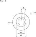
- FIG. 2 is a sectional view of the sealing assembly 17 and FIG. 3 is a plan view of the sealing assembly 17.
- the sealing assembly 17 includes a metal plate and has a projection 30 obtained by allowing the metal plate to expand toward the outside of the battery case 15, and a flange part 31 formed around the projection 30.
- the projection 30 has an upward projecting shape convex toward the upside and includes an inclined part 33 inclined so as to be gradually apart from the electrode assembly 14 as going toward the inside from the outside of the sealing assembly 17 in the radial direction. Further, a thin part which has a smaller thickness than the portion except the inclined part 33 and takes priority in fracturing when the internal pressure of the battery case 15 exceeds a predetermined threshold is formed in at least part of the inclined part 33.
- the predetermined threshold is properly set based on a battery capacity, a use, and the like.
- the sealing assembly 17 is fixed to the exterior can 16 via the gasket 23 by the flange part 31 pinched and held by the upper end part of the exterior can 16 folded to the inside of the battery case 15 and the grooved part 22.
- the flange part 31 is arranged along the radial direction of the exterior can 16.
- the projection 30 has a circular shape in plan view and preferably has a substantially perfect circular shape in plan view.
- substantially perfect circular means to include a perfect circular shape and shapes which can be substantially recognized as a perfect circle.
- the flange part 31 preferably has an annular shape in plan view having substantially constant inner diameter and outer diameter. The outer diameter of the flange 31 can be properly modified to meet the shape of the battery case in the case of applying the sealing assembly 17 to a rectangular battery, or the other case.
- the sealing assembly 17 does not have a downward projecting shape convex toward the inside of the battery case 15 and does not have an inversion part to deform from a downward projecting shape to an upward projecting shape when the internal pressure of the battery rises.
- a conventional sealing assembly having such an inversion part since the thickness of the inversion part needs to be small in order to allow plastic deformation, it is difficult to enhance the shock resistance of the sealing assembly.
- the shock resistance can be enhanced in such a range that the thin part fractures when the internal pressure of the battery rises.
- the projection 30 preferably has a top part 32 enclosed by the inclined part 33.
- the top part 32 is a portion most expanding toward the outside of the battery case 15.
- the top part 32 and the inclined part 33 are preferably flat, and a bent part exists at the boundary position between those.
- the top part 32 is formed to be substantially parallel to the flange part 31 and arranged along the radial direction of the exterior can 16.
- the top part 32 is formed into a substantially perfect circular shape in plan view with the center of the sealing assembly 17 and the projection 30 in the radial direction being as its center.
- a diameter ⁇ 1 of the top part 32 is preferably 20% to 70% of the diameter of the sealing assembly 17, still preferably 35% to 50% thereof.
- the inclined part 33 is formed into an annular shape in plan view between the flange part 31 and the top part 32 and formed into a tapered shape which is gradually apart from the electrode assembly 14 as going closer to the top part 32.
- a bent part having the inclined part 33 bent toward the upside exists at the boundary position between the flange part 31 and the inclined part 33.
- An angle ⁇ formed by the outer surface of the flange part 31 and the outer surface of the inclined part 33 is preferably 90° to 160°, still preferably 90° to 135°. When the angle ⁇ is in the range, tensile stress readily acts on the inclined part 33 when the internal pressure of the battery case 15 rises, and it is easy to cause the thin part to fracture.
- the inclined part 33 preferably has an annular shape in plan view having substantially constant inner diameter and outer diameter.
- the inclined part 33 is formed into an annular shape in plan view with the center of the sealing assembly 17 and the projection 30 in the radial direction being as its center.
- a diameter ⁇ 2 of the projection 30 is, for example, 50% to 80% of the diameter of the sealing assembly 17 or 55% to 70% thereof.
- the diameter ⁇ 1 of the top part 32 is, for example, 60% to 80% of the diameter ⁇ 2 of the projection 30 or 65% to 75% thereof.
- the thin part of the inclined part 33 fractures when the internal pressure of the battery case 15 rises upon occurrence of abnormality in the sealed battery 10. Since when the internal pressure of the battery case 15 rises, the tensile stress acts on the inclined part 33, forming the thin part in the inclined part 33 can cause the thin part to fracture using the tensile stress. Therefore, according to the sealing assembly 17, the gas discharge performance can be realized to be further more stable while maintaining the thickness of the inclined part 33 in such a range that the desired shock resistance can be secured.
- the sealed battery 10 may have a structure in which the negative electrode lead 21 is connected to the flange part 31.
- the sealing assembly 17 is the negative electrode external terminal.
- the sealing assembly 17 may be constituted of a plurality of components in the range which does not impair the object(s) of the present disclosure. Note that in order to reduce the number of components, to reduce the thickness of the sealing assembly 17, and to reduce production costs, the sealing assembly 17 is preferably constituted of one metal plate.
- the sealing assembly 17 is, for example, manufactured by performing press processing on one metal plate so as to be convex toward the outside of the battery case 15.
- a preferable example of the metal plate is an aluminum alloy plate the main component of which is aluminum.
- the thickness of the metal plate is not specially limited but is 0.2 mm to 2 mm, for example.
- the thicknesses of the top part 32 and the flange part 31 of the projection 30 may be the same or may be different.
- a thickness T2 of the thin part is not specially limited as long as the desired shock resistance can be secured and it fractures when the internal pressure of the battery case 15 rises, but the thickness is preferably set to be 30% to 50% relative to a thickness T1 of the top part 32, still preferably 35% to 45%.
- an average thickness or a thickness at the thinnest portion is preferably set as a reference (the same holds true for the thickness T1).
- a specific example of the thickness T2 is 0.1 mm to 0.3 mm. With the thickness T2 being in this range, high durability and stable gas discharge performance can be compatible with each other.
- the thickness T2 is preferably set to be 30% to 50% relative to the thickness of the flange part 31, still preferably 35% to 45%.
- the thin part is preferably formed in a range exceeding 20% of the inclined part 33.
- “exceeding 20% of the inclined part 33” means that the area of the thin part exceeds 20% of the total area of the inclined part 33 in the state where the sealing assembly 17 is viewed in plan view (or in bottom view).
- the thin part may be formed in a range exceeding 50% of the inclined part 33 or may be formed in a range exceeding 90% thereof.
- the width of the thin part is preferably constant along the circumferential direction of the inclined part 33.
- the thin part is formed in the whole inclined part 33.
- the thickness T2 of the thin part is substantially constant across the whole inclined part 33.
- the thickness of the inclined part 33 is smaller than the thicknesses of the other portions (the flange part 31 and the top part 32) across the whole inclined part 33.
- the inclined part 33 has, for example, a thickness which is 30% to 50% of the thickness T1 of the top part 32 or 35% to 45% thereof.
- the thickness T1 is also constant across the whole top part 32.
Landscapes
- Chemical & Material Sciences (AREA)
- Chemical Kinetics & Catalysis (AREA)
- Electrochemistry (AREA)
- General Chemical & Material Sciences (AREA)
- Sealing Battery Cases Or Jackets (AREA)
- Gas Exhaust Devices For Batteries (AREA)
- Connection Of Batteries Or Terminals (AREA)
Abstract
Description
- The present disclosure relates to a sealed battery.
- There is conventionally widely known a sealed battery comprising a battery case including a bottomed tubular exterior can and a sealing assembly sealing an opening of the exterior can (for example, refer to PATENT LITERATURE 1). PATENT LITERATURE 1 discloses a sealed battery comprising a sealing assembly including: a vent member the outer shape of which is a circular shape; a metal plate arranged more inside the battery case than the vent member and connected to the center part of the vent member; and an annular insulating member interposed between the outer periphery of the vent member and the outer periphery of the metal plate. In the sealing assembly, the vent member includes an inclined region the thickness of which continuously decreases along the radial direction from its inner periphery to its outer periphery, and has a downward projecting shape expanding toward the inside of the battery case.
- PATENT LITERATURE 1:
WO2016/157749 - Sealing assemblies have a function as a safety vent which fractures when the internal pressure of the battery case rises upon occurrence of abnormality in the battery and enables discharge of gas, and sealed batteries are being requested to inhibit a variation in working pressure of the vent among those to make gas discharge performance more stable. In addition, the sealing assemblies are requested to have predetermined shock resistance so as not to be damaged due to external force which can acts on the batteries in the process of production of these, in the normal state of use of these, or in the other situation.
- A sealed battery which is an aspect of the present disclosure comprises: a battery case including a bottomed tubular exterior can and a sealing assembly sealing an opening of the exterior can; and an electrode assembly housed in the battery case, wherein the sealing assembly includes a metal plate, and the metal plate includes a projection expanding toward the outside of the battery case, and a flange part formed around the projection. The projection includes an inclined part inclined so as to be gradually apart from the electrode assembly as going toward an inside from an outside of the sealing assembly in a radial direction, and a thin part that has a smaller thickness than a portion except the inclined part and takes priority in fracturing when an internal pressure of the battery case exceeds a predetermined threshold is formed in at least part of the inclined part.
- According to an aspect of the present disclosure, there may be provided a sealed battery which achieves stable gas discharge performance upon occurrence of abnormality in the battery and has excellent shock resistance.
-
-
FIG. 1 is a sectional view of a sealed battery which is an example of embodiments. -
FIG. 2 is a sectional view of a sealing assembly which is an example of embodiments. -
FIG. 3 is a plan view of a sealing assembly which is an example of embodiments. - For the sealed battery, it is an important problem to realize the stable gas discharge performance upon occurrence of abnormality while securing predetermined shock resistance. The inventors have intensively conducted study on such a problem in order to solve it and have found a novel sealing assembly in which a thin part is formed in an inclined part of a projection expanding toward the outside of the battery case. In general, a conventional sealing assembly has a downward projecting shape as exemplarily shown in PATENT LITERATURE 1, and when the internal pressure of the battery rises, forms a discharge path through shear breakage of an engraved part formed on the metal plate. In this case, in order to cause the engraved part to fracture stably at low internal pressure, the thickness of the engraved part has needed to be very small. Meanwhile, it has been difficult to secure the strength of the sealing assembly so as to be durable against external force such as drop shock and vibration, when the thickness of the engraved part is too small.
- A sealing assembly of a sealed battery according to the present disclosure is designed such that a thin part of an inclined part is caused to fracture using tensile stress which acts on the inclined part when the internal pressure of the battery rises. In this case, the gas discharge performance can be realized to be further more stable while maintaining the thickness of the inclined part in such a range that the desired shock resistance can be secured. In other words, according to the sealing assembly of the present disclosure, excellent shock resistance and excellent gas discharge performance can be compatible with each other.
- Hereafter, an example of embodiments of the present disclosure will be described in detail. While there is hereafter exemplarily illustrated, as an example of embodiments of a sealed battery according to the present disclosure, a cylindrical battery in which a winding-
type electrode assembly 14 is housed in acylindrical battery case 15, the battery may be a rectangular battery comprising a rectangular battery case. Moreover, the electrode assembly may be a laminate type one configured by alternately laminating a plurality of positive electrodes and a plurality of negative electrodes via separators. In the present specification, the side of asealing assembly 17 of thebattery case 15 will be described as being "upward", and the bottom part side of an exterior can 16 thereof will be described as being "downward" for convenience of description. -
FIG. 1 is a sectional view of a sealedbattery 10 which is an example of embodiments. As exemplarily shown inFIG. 1 , the sealedbattery 10 comprising: thebattery case 15 including the bottomed tubular exterior can 16 and thesealing assembly 17 sealing an opening of the exterior can 16; and theelectrode assembly 14 housed in thebattery case 15. Moreover, an electrolyte is housed in thebattery case 15. Theelectrode assembly 14 includes apositive electrode 11, anegative electrode 12, andseparators 13 interposed between thepositive electrode 11 and thenegative electrode 12. Theelectrode assembly 14 has a winding structure configured by winding thepositive electrode 11 and thenegative electrode 12 via theseparators 13. Moreover, the sealedbattery 10 comprises a resin-madegasket 23 arranged between the exterior can 16 and thesealing assembly 17. - The electrolyte may be any of an aqueous electrolyte and a non-aqueous electrolyte. A preferable example of the sealed
battery 10 is a non-aqueous electrolyte secondary battery, such as a lithium ion battery, using a non-aqueous electrolyte. The non-aqueous electrolyte includes, for example, a non-aqueous solvent and an electrolyte salt dissolved in the non-aqueous solvent. For the non-aqueous solvent, there are used esters, ethers, nitriles, amides, mixed solvents of two or more of these, and the like. The non-aqueous solvent may contain a halogen-substituted substance having halogen atom(s) such as fluorine substituted for at least one or some of hydrogens in these solvents. The non-aqueous electrolyte is not limited to a liquid electrolyte but may be a solid electrolyte using a gelatinous polymer or the like. For the electrolyte salt, there is used a lithium salt such as LiPF6. - The
electrode assembly 14 includes thepositive electrode 11 which is long, thenegative electrode 12 which is long, the twoseparators 13 which are long, apositive electrode lead 20 joined to thepositive electrode 11, and anegative electrode lead 21 joined to thenegative electrode 12. In order to inhibit precipitation of lithium, thenegative electrode 12 is formed in dimensions one size larger than those of thepositive electrode 11. Namely, thenegative electrode 12 is formed to be longer in the longitudinal direction and the transverse direction (up-down direction) than thepositive electrode 11. The twoseparators 13 are formed in dimensions one size larger, at least, than thepositive electrode 11, and are arranged, for example, so as to interpose thepositive electrode 11. - The
positive electrode 11 includes a positive electrode current collector, and positive electrode mixture layers provided on both sides of the positive electrode current collector. For the positive electrode current collector, there can be used a foil of a metal such as aluminum and aluminum alloy, which is stable in the potential range of thepositive electrode 11, a film having the metal disposed in its surface layers, or the other material. The positive electrode mixture layer includes a positive electrode active material, a conductive agent such as acetylene black, and a binder such as polyvinylidene fluoride (PVdF). Thepositive electrode 11 can be produced by applying positive electrode mixture slurry including the positive electrode active material, the conductive agent, the binder, and the like onto the positive electrode current collector, and drying, and compressing afterward, the coating film to form the positive electrode mixture layers on both sides of the positive electrode current collector. - For the positive electrode active material, a lithium-transition metal composite oxide is used, for example. Examples of metal elements contained in the lithium-transition metal composite oxide include Ni, Co, Mn, Al, B, Mg, Ti, V, Cr, Fe, Cu, Zn, Ga, Sr, Zr, Nb, In, Sn, Ta, and W. A preferable example of the lithium-transition metal composite oxide is a lithium-transition metal composite oxide containing at least one of Ni, Co, and Mn. Specific examples thereof include a composite oxide containing Ni, Co, and Mn, and a composite oxide containing Ni, Co, and Al.
- The
negative electrode 12 has a negative electrode current collector, and negative electrode mixture layers provided on both sides of the negative electrode current collector. For the negative electrode current collector, there can be used a foil of a metal such as copper and copper alloy, which is stable in the potential range of thenegative electrode 12, a film having the metal disposed in its surface layers, or the other material. The negative electrode mixture layer includes a negative electrode active material, and a binder such as styrene-butadiene rubber (SBR). Thenegative electrode 12 can be produced by applying negative electrode mixture slurry including the negative electrode active material, the binder, and the like onto the negative electrode current collector, and drying, and compressing afterward, the coating film to form the negative electrode mixture layers on both sides of the negative electrode current collector. - For the negative electrode active material, there is used, for example, graphite such as natural graphite such as flaky graphite, lumpy graphite, and earthy graphite, artificial graphite such as artificial lumpy graphite and graphitized mesophase carbon microbeads, or the other material. For the negative electrode active material, there may be used a metal which is alloyed with lithium, such as Si and Sn, an alloy containing the metal, a compound containing the metal, or the like, and these may be used together with the graphite. Specific examples of the compound include silicon compounds expressed as SiOx (0.5≤x≤1.6).
-
Insulating plates electrode assembly 14. In the example ofFIG. 1 , thepositive electrode lead 20 attached to thepositive electrode 11 extends to the sealingassembly 17 side through a through hole of the insulatingplate 18, and thenegative electrode lead 21 attached to thenegative electrode 12 extends to the bottom part side of the exterior can 16 through the outside of the insulatingplate 19. Thepositive electrode lead 20 is connected to the inner surface, of the sealingassembly 17, that faces the inside of thebattery case 15 by welding or the like, and sealingassembly 17 is a positive electrode external terminal. Thenegative electrode lead 21 is connected to the inner surface of the bottom part of the exterior can 16 by welding or the like, and the exterior can 16 is a negative electrode external terminal. - As mentioned above, the
battery case 15 is constituted of the bottomed tubular exterior can 16 and the sealingassembly 17 sealing the opening of the exterior can 16. The exterior can 16 is a bottomed cylindrical metal-made container. Thegasket 23 is provided between the exterior can 16 and the sealingassembly 17 and seals the inner space of thebattery case 15. The exterior can 16 includes agrooved part 22 which is formed, for example, by spinning processing on its lateral surface part from the outside and supports the sealingassembly 17. Thegrooved part 22 is preferably formed into an annular shape along the circumferential direction of the exterior can 16, and supports the sealingassembly 17 on its upper surface. Moreover, the upper end part of the exterior can 16 is folded to the inside of thebattery case 15 and crimped on the peripheral edge of the sealingassembly 17. The opening of the exterior can 16 has a circular shape in plan view, and likewise, the sealingassembly 17 also has a circular shape in plan view. - Hereafter, the sealing
assembly 17 will be described in detail with reference toFIG. 2 andFIG. 3 .FIG. 2 is a sectional view of the sealingassembly 17 andFIG. 3 is a plan view of the sealingassembly 17. - As exemplarily shown in
FIG. 2 andFIG. 3 , the sealingassembly 17 includes a metal plate and has aprojection 30 obtained by allowing the metal plate to expand toward the outside of thebattery case 15, and aflange part 31 formed around theprojection 30. Theprojection 30 has an upward projecting shape convex toward the upside and includes aninclined part 33 inclined so as to be gradually apart from theelectrode assembly 14 as going toward the inside from the outside of the sealingassembly 17 in the radial direction. Further, a thin part which has a smaller thickness than the portion except theinclined part 33 and takes priority in fracturing when the internal pressure of thebattery case 15 exceeds a predetermined threshold is formed in at least part of theinclined part 33. The predetermined threshold is properly set based on a battery capacity, a use, and the like. - The sealing
assembly 17 is fixed to the exterior can 16 via thegasket 23 by theflange part 31 pinched and held by the upper end part of the exterior can 16 folded to the inside of thebattery case 15 and thegrooved part 22. Theflange part 31 is arranged along the radial direction of the exterior can 16. Theprojection 30 has a circular shape in plan view and preferably has a substantially perfect circular shape in plan view. Herein, "substantially perfect circular" means to include a perfect circular shape and shapes which can be substantially recognized as a perfect circle. Theflange part 31 preferably has an annular shape in plan view having substantially constant inner diameter and outer diameter. The outer diameter of theflange 31 can be properly modified to meet the shape of the battery case in the case of applying the sealingassembly 17 to a rectangular battery, or the other case. - The sealing
assembly 17 does not have a downward projecting shape convex toward the inside of thebattery case 15 and does not have an inversion part to deform from a downward projecting shape to an upward projecting shape when the internal pressure of the battery rises. As to a conventional sealing assembly having such an inversion part, since the thickness of the inversion part needs to be small in order to allow plastic deformation, it is difficult to enhance the shock resistance of the sealing assembly. On the other hand, as to the sealingassembly 17 not having an inversion part, the shock resistance can be enhanced in such a range that the thin part fractures when the internal pressure of the battery rises. - The
projection 30 preferably has atop part 32 enclosed by theinclined part 33. Thetop part 32 is a portion most expanding toward the outside of thebattery case 15. Thetop part 32 and theinclined part 33 are preferably flat, and a bent part exists at the boundary position between those. Thetop part 32 is formed to be substantially parallel to theflange part 31 and arranged along the radial direction of the exterior can 16. In the example shown inFIG. 3 , thetop part 32 is formed into a substantially perfect circular shape in plan view with the center of the sealingassembly 17 and theprojection 30 in the radial direction being as its center. A diameter φ1 of thetop part 32 is preferably 20% to 70% of the diameter of the sealingassembly 17, still preferably 35% to 50% thereof. - The
inclined part 33 is formed into an annular shape in plan view between theflange part 31 and thetop part 32 and formed into a tapered shape which is gradually apart from theelectrode assembly 14 as going closer to thetop part 32. A bent part having theinclined part 33 bent toward the upside exists at the boundary position between theflange part 31 and theinclined part 33. An angle θ formed by the outer surface of theflange part 31 and the outer surface of theinclined part 33 is preferably 90° to 160°, still preferably 90° to 135°. When the angle θ is in the range, tensile stress readily acts on theinclined part 33 when the internal pressure of thebattery case 15 rises, and it is easy to cause the thin part to fracture. - The
inclined part 33 preferably has an annular shape in plan view having substantially constant inner diameter and outer diameter. In the example shown inFIG. 3 , theinclined part 33 is formed into an annular shape in plan view with the center of the sealingassembly 17 and theprojection 30 in the radial direction being as its center. A diameter φ2 of theprojection 30 is, for example, 50% to 80% of the diameter of the sealingassembly 17 or 55% to 70% thereof. The diameter φ1 of thetop part 32 is, for example, 60% to 80% of the diameter φ2 of theprojection 30 or 65% to 75% thereof. - In the sealing
assembly 17, the thin part of theinclined part 33 fractures when the internal pressure of thebattery case 15 rises upon occurrence of abnormality in the sealedbattery 10. Since when the internal pressure of thebattery case 15 rises, the tensile stress acts on theinclined part 33, forming the thin part in theinclined part 33 can cause the thin part to fracture using the tensile stress. Therefore, according to the sealingassembly 17, the gas discharge performance can be realized to be further more stable while maintaining the thickness of theinclined part 33 in such a range that the desired shock resistance can be secured. - The sealed
battery 10 may have a structure in which thenegative electrode lead 21 is connected to theflange part 31. In this case, the sealingassembly 17 is the negative electrode external terminal. Moreover, the sealingassembly 17 may be constituted of a plurality of components in the range which does not impair the object(s) of the present disclosure. Note that in order to reduce the number of components, to reduce the thickness of the sealingassembly 17, and to reduce production costs, the sealingassembly 17 is preferably constituted of one metal plate. - The sealing
assembly 17 is, for example, manufactured by performing press processing on one metal plate so as to be convex toward the outside of thebattery case 15. A preferable example of the metal plate is an aluminum alloy plate the main component of which is aluminum. The thickness of the metal plate is not specially limited but is 0.2 mm to 2 mm, for example. The thicknesses of thetop part 32 and theflange part 31 of theprojection 30 may be the same or may be different. - A thickness T2 of the thin part is not specially limited as long as the desired shock resistance can be secured and it fractures when the internal pressure of the
battery case 15 rises, but the thickness is preferably set to be 30% to 50% relative to a thickness T1 of thetop part 32, still preferably 35% to 45%. When the thickness T2 is not constant, an average thickness or a thickness at the thinnest portion is preferably set as a reference (the same holds true for the thickness T1). A specific example of the thickness T2 is 0.1 mm to 0.3 mm. With the thickness T2 being in this range, high durability and stable gas discharge performance can be compatible with each other. Moreover, the thickness T2 is preferably set to be 30% to 50% relative to the thickness of theflange part 31, still preferably 35% to 45%. - The thin part is preferably formed in a range exceeding 20% of the
inclined part 33. Herein, "exceeding 20% of theinclined part 33" means that the area of the thin part exceeds 20% of the total area of theinclined part 33 in the state where the sealingassembly 17 is viewed in plan view (or in bottom view). The thin part may be formed in a range exceeding 50% of theinclined part 33 or may be formed in a range exceeding 90% thereof. The width of the thin part is preferably constant along the circumferential direction of theinclined part 33. - In the present embodiment, the thin part is formed in the whole
inclined part 33. Moreover, the thickness T2 of the thin part is substantially constant across the wholeinclined part 33. In other words, the thickness of theinclined part 33 is smaller than the thicknesses of the other portions (theflange part 31 and the top part 32) across the wholeinclined part 33. Theinclined part 33 has, for example, a thickness which is 30% to 50% of the thickness T1 of thetop part 32 or 35% to 45% thereof. In the present embodiment, the thickness T1 is also constant across the wholetop part 32. - 10 sealed battery, 11 positive electrode, 12 negative electrode, 13 separator, 14 electrode assembly, 15 battery case, 16 exterior can, 17 sealing assembly, 18, 19 insulating plate, 20 positive electrode lead, 21 negative electrode lead, 22 grooved part, 23 gasket, 30 projection, 31 flange part, 32 top part, 33 inclined part
Claims (4)
- A sealed battery, comprising:a battery case including a bottomed tubular exterior can and a sealing assembly sealing an opening of the exterior can; andan electrode assembly housed in the battery case, whereinthe sealing assembly includes a metal plate,the metal plate includesa projection expanding toward the outside of the battery case, anda flange part formed around the projection,the projection includes an inclined part inclined so as to be gradually apart from the electrode assembly as going toward an inside from an outside of the sealing assembly in a radial direction, anda thin part that has a smaller thickness than a portion except the inclined part and takes priority in fracturing when an internal pressure of the battery case exceeds a predetermined threshold is formed in at least part of the inclined part.
- The sealed battery according to claim 1, whereinthe metal plate constitutes a top plate of the sealing assembly, andan electrode lead connected to a positive electrode or a negative electrode of the electrode assembly is welded to the flange part.
- The sealed battery according to claim 1 or 2, whereinthe projection includes a flat top part enclosed by the inclined part, anda thickness of the thin part is 30% to 50% of a thickness of the top part.
- The sealed battery according to any one of claims 1 to 3, wherein the thin part is formed in a range exceeding 20% of the inclined part.
Applications Claiming Priority (2)
| Application Number | Priority Date | Filing Date | Title |
|---|---|---|---|
| JP2018239241 | 2018-12-21 | ||
| PCT/JP2019/044541 WO2020129480A1 (en) | 2018-12-21 | 2019-11-13 | Sealed battery |
Publications (3)
| Publication Number | Publication Date |
|---|---|
| EP3902024A1 true EP3902024A1 (en) | 2021-10-27 |
| EP3902024A4 EP3902024A4 (en) | 2022-03-02 |
| EP3902024B1 EP3902024B1 (en) | 2026-04-01 |
Family
ID=71100438
Family Applications (1)
| Application Number | Title | Priority Date | Filing Date |
|---|---|---|---|
| EP19898426.2A Active EP3902024B1 (en) | 2018-12-21 | 2019-11-13 | Sealed battery |
Country Status (5)
| Country | Link |
|---|---|
| US (1) | US12176567B2 (en) |
| EP (1) | EP3902024B1 (en) |
| JP (1) | JP7531402B2 (en) |
| CN (1) | CN113169399A (en) |
| WO (1) | WO2020129480A1 (en) |
Families Citing this family (3)
| Publication number | Priority date | Publication date | Assignee | Title |
|---|---|---|---|---|
| CN115699437B (en) * | 2020-11-25 | 2025-02-18 | 宁德时代新能源科技股份有限公司 | Battery cell and manufacturing method and system thereof, battery and electric device |
| EP4318768A4 (en) * | 2021-03-25 | 2025-05-21 | Panasonic Energy Co., Ltd. | Sealed battery |
| CN118476093A (en) * | 2021-12-24 | 2024-08-09 | 松下新能源株式会社 | Cylindrical battery |
Family Cites Families (9)
| Publication number | Priority date | Publication date | Assignee | Title |
|---|---|---|---|---|
| KR100978092B1 (en) * | 2008-05-30 | 2010-08-25 | 삼성에스디아이 주식회사 | Cap assembly and secondary battery having the same |
| JP2014086242A (en) * | 2012-10-23 | 2014-05-12 | Panasonic Corp | Sealed secondary battery |
| CN104956516B (en) | 2013-01-31 | 2017-09-26 | 三洋电机株式会社 | Enclosed-type battery |
| WO2014171293A1 (en) * | 2013-04-16 | 2014-10-23 | 株式会社ソーデナガノ | Cell case |
| WO2015146078A1 (en) * | 2014-03-28 | 2015-10-01 | 三洋電機株式会社 | Cylindrical sealed battery and battery pack |
| JP6538650B2 (en) * | 2014-03-28 | 2019-07-03 | 三洋電機株式会社 | Cylindrical sealed battery |
| US10615401B2 (en) | 2015-03-27 | 2020-04-07 | Sanyo Electric Co., Ltd. | Cylindrical batteries |
| KR101850182B1 (en) * | 2015-04-10 | 2018-04-18 | 주식회사 엘지화학 | Cap Assembly Of Cylindrical Type Secondary Battery And Manufacturing Method Thereof |
| KR102761907B1 (en) * | 2017-01-05 | 2025-02-05 | 삼성에스디아이 주식회사 | Secondary Battery |
-
2019
- 2019-11-13 US US17/311,834 patent/US12176567B2/en active Active
- 2019-11-13 CN CN201980080921.4A patent/CN113169399A/en active Pending
- 2019-11-13 WO PCT/JP2019/044541 patent/WO2020129480A1/en not_active Ceased
- 2019-11-13 JP JP2020561221A patent/JP7531402B2/en active Active
- 2019-11-13 EP EP19898426.2A patent/EP3902024B1/en active Active
Also Published As
| Publication number | Publication date |
|---|---|
| JPWO2020129480A1 (en) | 2021-11-11 |
| US12176567B2 (en) | 2024-12-24 |
| JP7531402B2 (en) | 2024-08-09 |
| EP3902024A4 (en) | 2022-03-02 |
| WO2020129480A1 (en) | 2020-06-25 |
| CN113169399A (en) | 2021-07-23 |
| EP3902024B1 (en) | 2026-04-01 |
| US20220021072A1 (en) | 2022-01-20 |
Similar Documents
| Publication | Publication Date | Title |
|---|---|---|
| EP3913701B1 (en) | Sealed battery | |
| US11876245B2 (en) | Sealed battery comprising an elastic deformation part that is folded | |
| EP1717878B1 (en) | Core member for a cylindrical lithium secondary battery | |
| US20220231357A1 (en) | Cylindrical battery | |
| JP7686570B2 (en) | Cylindrical battery | |
| US12176567B2 (en) | Sealed battery | |
| EP4318768A1 (en) | Sealed battery | |
| EP4120447A1 (en) | Hermetically sealed battery | |
| US20230114471A1 (en) | Cylindrical battery | |
| JP2022031997A (en) | Sealed battery | |
| WO2023054005A1 (en) | Cylindrical battery | |
| EP4080648B1 (en) | Cylindrical battery | |
| EP4270613A1 (en) | Hermetically sealed battery | |
| US20250273834A1 (en) | Cylindrical battery | |
| EP4456280A1 (en) | Cylindrical battery | |
| WO2024185394A1 (en) | Gasket, cylindrical battery, and cylindrical battery manufacturing method | |
| WO2023189790A1 (en) | Cylindrical battery | |
| US11824168B2 (en) | Battery | |
| EP4679620A1 (en) | Cylindrical battery | |
| US20250379301A1 (en) | Sealed battery | |
| EP4583298A1 (en) | Cylindrical battery | |
| WO2023181853A1 (en) | Cylindrical battery | |
| WO2024070513A1 (en) | Cylindrical battery | |
| CN116711144A (en) | Cylindrical battery | |
| WO2013002173A1 (en) | Sealed battery |
Legal Events
| Date | Code | Title | Description |
|---|---|---|---|
| STAA | Information on the status of an ep patent application or granted ep patent |
Free format text: STATUS: THE INTERNATIONAL PUBLICATION HAS BEEN MADE |
|
| PUAI | Public reference made under article 153(3) epc to a published international application that has entered the european phase |
Free format text: ORIGINAL CODE: 0009012 |
|
| STAA | Information on the status of an ep patent application or granted ep patent |
Free format text: STATUS: REQUEST FOR EXAMINATION WAS MADE |
|
| 17P | Request for examination filed |
Effective date: 20210518 |
|
| AK | Designated contracting states |
Kind code of ref document: A1 Designated state(s): AL AT BE BG CH CY CZ DE DK EE ES FI FR GB GR HR HU IE IS IT LI LT LU LV MC MK MT NL NO PL PT RO RS SE SI SK SM TR |
|
| REG | Reference to a national code |
Ref country code: DE Ref legal event code: R079 Free format text: PREVIOUS MAIN CLASS: H01M0002040000 Ipc: H01M0050152000 Ref document number: 602019083234 Country of ref document: DE |
|
| A4 | Supplementary search report drawn up and despatched |
Effective date: 20220127 |
|
| RIC1 | Information provided on ipc code assigned before grant |
Ipc: H01M 50/342 20210101ALI20220121BHEP Ipc: H01M 50/531 20210101ALI20220121BHEP Ipc: H01M 50/167 20210101ALI20220121BHEP Ipc: H01M 50/107 20210101ALI20220121BHEP Ipc: H01M 50/152 20210101AFI20220121BHEP |
|
| DAV | Request for validation of the european patent (deleted) | ||
| DAX | Request for extension of the european patent (deleted) | ||
| GRAP | Despatch of communication of intention to grant a patent |
Free format text: ORIGINAL CODE: EPIDOSNIGR1 |
|
| STAA | Information on the status of an ep patent application or granted ep patent |
Free format text: STATUS: GRANT OF PATENT IS INTENDED |
|
| INTG | Intention to grant announced |
Effective date: 20251015 |
|
| P01 | Opt-out of the competence of the unified patent court (upc) registered |
Free format text: CASE NUMBER: UPC_APP_0016417_3902024/2025 Effective date: 20251209 |
|
| GRAS | Grant fee paid |
Free format text: ORIGINAL CODE: EPIDOSNIGR3 |
|
| GRAA | (expected) grant |
Free format text: ORIGINAL CODE: 0009210 |
|
| STAA | Information on the status of an ep patent application or granted ep patent |
Free format text: STATUS: THE PATENT HAS BEEN GRANTED |
|
| RAP3 | Party data changed (applicant data changed or rights of an application transferred) |
Owner name: SANYO ELECTRIC CO., LTD. |
|
| RAP1 | Party data changed (applicant data changed or rights of an application transferred) |
Owner name: PANASONIC ENERGY CO., LTD. |
|
| AK | Designated contracting states |
Kind code of ref document: B1 Designated state(s): AL AT BE BG CH CY CZ DE DK EE ES FI FR GB GR HR HU IE IS IT LI LT LU LV MC MK MT NL NO PL PT RO RS SE SI SK SM TR |
|
| REG | Reference to a national code |
Ref country code: CH Ref legal event code: F10 Free format text: ST27 STATUS EVENT CODE: U-0-0-F10-F00 (AS PROVIDED BY THE NATIONAL OFFICE) Effective date: 20260401 Ref country code: GB Ref legal event code: FG4D |
|
| REG | Reference to a national code |
Ref country code: DE Ref legal event code: R096 Ref document number: 602019083234 Country of ref document: DE |
|
| REG | Reference to a national code |
Ref country code: IE Ref legal event code: FG4D |
|
| REG | Reference to a national code |
Ref country code: NL Ref legal event code: MP Effective date: 20260401 |