EP3901602A1 - Method of manufacturing magnetostrictive torque sensor shaft - Google Patents
Method of manufacturing magnetostrictive torque sensor shaft Download PDFInfo
- Publication number
- EP3901602A1 EP3901602A1 EP19900001.9A EP19900001A EP3901602A1 EP 3901602 A1 EP3901602 A1 EP 3901602A1 EP 19900001 A EP19900001 A EP 19900001A EP 3901602 A1 EP3901602 A1 EP 3901602A1
- Authority
- EP
- European Patent Office
- Prior art keywords
- shaft
- torque sensor
- heat treatment
- magnetostrictive torque
- manufacturing
- Prior art date
- Legal status (The legal status is an assumption and is not a legal conclusion. Google has not performed a legal analysis and makes no representation as to the accuracy of the status listed.)
- Granted
Links
Images




Classifications
-
- G—PHYSICS
- G01—MEASURING; TESTING
- G01L—MEASURING FORCE, STRESS, TORQUE, WORK, MECHANICAL POWER, MECHANICAL EFFICIENCY, OR FLUID PRESSURE
- G01L3/00—Measuring torque, work, mechanical power, or mechanical efficiency, in general
- G01L3/02—Rotary-transmission dynamometers
- G01L3/04—Rotary-transmission dynamometers wherein the torque-transmitting element comprises a torsionally-flexible shaft
- G01L3/10—Rotary-transmission dynamometers wherein the torque-transmitting element comprises a torsionally-flexible shaft involving electric or magnetic means for indicating
- G01L3/101—Rotary-transmission dynamometers wherein the torque-transmitting element comprises a torsionally-flexible shaft involving electric or magnetic means for indicating involving magnetic or electromagnetic means
- G01L3/102—Rotary-transmission dynamometers wherein the torque-transmitting element comprises a torsionally-flexible shaft involving electric or magnetic means for indicating involving magnetic or electromagnetic means involving magnetostrictive means
-
- B—PERFORMING OPERATIONS; TRANSPORTING
- B24—GRINDING; POLISHING
- B24C—ABRASIVE OR RELATED BLASTING WITH PARTICULATE MATERIAL
- B24C1/00—Methods for use of abrasive blasting for producing particular effects; Use of auxiliary equipment in connection with such methods
- B24C1/10—Methods for use of abrasive blasting for producing particular effects; Use of auxiliary equipment in connection with such methods for compacting surfaces, e.g. shot-peening
-
- C—CHEMISTRY; METALLURGY
- C21—METALLURGY OF IRON
- C21D—MODIFYING THE PHYSICAL STRUCTURE OF FERROUS METALS; GENERAL DEVICES FOR HEAT TREATMENT OF FERROUS OR NON-FERROUS METALS OR ALLOYS; MAKING METAL MALLEABLE, e.g. BY DECARBURISATION OR TEMPERING
- C21D1/00—General methods or devices for heat treatment, e.g. annealing, hardening, quenching or tempering
- C21D1/06—Surface hardening
-
- C—CHEMISTRY; METALLURGY
- C21—METALLURGY OF IRON
- C21D—MODIFYING THE PHYSICAL STRUCTURE OF FERROUS METALS; GENERAL DEVICES FOR HEAT TREATMENT OF FERROUS OR NON-FERROUS METALS OR ALLOYS; MAKING METAL MALLEABLE, e.g. BY DECARBURISATION OR TEMPERING
- C21D1/00—General methods or devices for heat treatment, e.g. annealing, hardening, quenching or tempering
- C21D1/18—Hardening; Quenching with or without subsequent tempering
- C21D1/25—Hardening, combined with annealing between 300 degrees Celsius and 600 degrees Celsius, i.e. heat refining ("Vergüten")
-
- C—CHEMISTRY; METALLURGY
- C21—METALLURGY OF IRON
- C21D—MODIFYING THE PHYSICAL STRUCTURE OF FERROUS METALS; GENERAL DEVICES FOR HEAT TREATMENT OF FERROUS OR NON-FERROUS METALS OR ALLOYS; MAKING METAL MALLEABLE, e.g. BY DECARBURISATION OR TEMPERING
- C21D1/00—General methods or devices for heat treatment, e.g. annealing, hardening, quenching or tempering
- C21D1/74—Methods of treatment in inert gas, controlled atmosphere, vacuum or pulverulent material
- C21D1/76—Adjusting the composition of the atmosphere
-
- C—CHEMISTRY; METALLURGY
- C21—METALLURGY OF IRON
- C21D—MODIFYING THE PHYSICAL STRUCTURE OF FERROUS METALS; GENERAL DEVICES FOR HEAT TREATMENT OF FERROUS OR NON-FERROUS METALS OR ALLOYS; MAKING METAL MALLEABLE, e.g. BY DECARBURISATION OR TEMPERING
- C21D7/00—Modifying the physical properties of iron or steel by deformation
- C21D7/02—Modifying the physical properties of iron or steel by deformation by cold working
- C21D7/04—Modifying the physical properties of iron or steel by deformation by cold working of the surface
- C21D7/06—Modifying the physical properties of iron or steel by deformation by cold working of the surface by shot-peening or the like
-
- C—CHEMISTRY; METALLURGY
- C21—METALLURGY OF IRON
- C21D—MODIFYING THE PHYSICAL STRUCTURE OF FERROUS METALS; GENERAL DEVICES FOR HEAT TREATMENT OF FERROUS OR NON-FERROUS METALS OR ALLOYS; MAKING METAL MALLEABLE, e.g. BY DECARBURISATION OR TEMPERING
- C21D8/00—Modifying the physical properties of ferrous metals or ferrous alloys by deformation combined with, or followed by, heat treatment
- C21D8/06—Modifying the physical properties of ferrous metals or ferrous alloys by deformation combined with, or followed by, heat treatment during manufacturing of rods or wires
-
- C—CHEMISTRY; METALLURGY
- C21—METALLURGY OF IRON
- C21D—MODIFYING THE PHYSICAL STRUCTURE OF FERROUS METALS; GENERAL DEVICES FOR HEAT TREATMENT OF FERROUS OR NON-FERROUS METALS OR ALLOYS; MAKING METAL MALLEABLE, e.g. BY DECARBURISATION OR TEMPERING
- C21D9/00—Heat treatment, e.g. annealing, hardening, quenching or tempering, adapted for particular articles; Furnaces therefor
- C21D9/0075—Heat treatment, e.g. annealing, hardening, quenching or tempering, adapted for particular articles; Furnaces therefor for rods of limited length
-
- C—CHEMISTRY; METALLURGY
- C21—METALLURGY OF IRON
- C21D—MODIFYING THE PHYSICAL STRUCTURE OF FERROUS METALS; GENERAL DEVICES FOR HEAT TREATMENT OF FERROUS OR NON-FERROUS METALS OR ALLOYS; MAKING METAL MALLEABLE, e.g. BY DECARBURISATION OR TEMPERING
- C21D9/00—Heat treatment, e.g. annealing, hardening, quenching or tempering, adapted for particular articles; Furnaces therefor
- C21D9/28—Heat treatment, e.g. annealing, hardening, quenching or tempering, adapted for particular articles; Furnaces therefor for plain shafts
-
- H—ELECTRICITY
- H10—SEMICONDUCTOR DEVICES; ELECTRIC SOLID-STATE DEVICES NOT OTHERWISE PROVIDED FOR
- H10N—ELECTRIC SOLID-STATE DEVICES NOT OTHERWISE PROVIDED FOR
- H10N35/00—Magnetostrictive devices
- H10N35/01—Manufacture or treatment
-
- Y—GENERAL TAGGING OF NEW TECHNOLOGICAL DEVELOPMENTS; GENERAL TAGGING OF CROSS-SECTIONAL TECHNOLOGIES SPANNING OVER SEVERAL SECTIONS OF THE IPC; TECHNICAL SUBJECTS COVERED BY FORMER USPC CROSS-REFERENCE ART COLLECTIONS [XRACs] AND DIGESTS
- Y10—TECHNICAL SUBJECTS COVERED BY FORMER USPC
- Y10T—TECHNICAL SUBJECTS COVERED BY FORMER US CLASSIFICATION
- Y10T29/00—Metal working
- Y10T29/47—Burnishing
- Y10T29/479—Burnishing by shot peening or blasting
Definitions
- the present invention relates to a method for manufacturing a magnetostrictive torque sensor shaft.
- the magnetostrictive torque sensor uses a shaft having magnetostrictive characteristic whose magnetic permeability changes when stress is applied, and detects a torque applied to the shaft by detecting a change in magnetic permeability of the shaft when the torque is applied and the shaft is twisted as a change in inductance of a detecting coil.
- the citation list information relating to the invention according to the present application includes Patent Document 1 .
- Patent Document 1 JP2018-112451A
- a steel material used for the shaft comprises a non-magnetic structure called retained austenite.
- the retained austenite is gamma-iron ( ⁇ -Fe) with face-centered cubic lattice structure in which the other elements are dissolved.
- the shaft includes a large amount of the non-magnetic retained austenite, the change in magnetic permeability when the torque is applied reduces, and thus it leads to decrease in sensitivity of the magnetostrictive torque sensor.
- the toughness of the shaft may decrease, so that the shaft may be cracked.
- the magnetostrictive torque sensor is used for, e.g., a transmission stroke control or an engine output control. Therefore, it is desirable to have a small error as much as possible to perform a reliable shift transmission.
- the object of the present invention is to provide a method for manufacturing a magnetostrictive torque sensor shaft to which a sensor portion of the magnetostrictive torque sensor is to be attached, the method comprising heat treatment step of subjecting an iron-based shaft member to a carburizing, quenching, and tempering process, and a shot peening step of performing shot peening using a steel shot media having a Vickers hardness at least equal to 1100 and at most equal to 1300 and being free of boron, at least in a position on the shaft member, after the heat treatment step, to which the sensor portion is to be attached.
- FIG. 1 A is a side view showing an example of a sensor portion of the torque sensor that is attached to a shaft.
- FIG. 1 B is a cross-sectional view taken along line A-A in FIG. 1 A .
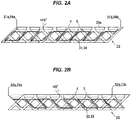
- FIG. 2 A is a plan view schematically showing a state in which a bobbin is deployed, which illustrates a first detecting coil and a fourth detecting coil.
- FIG. 2 B is a plan view schematically showing a state in which the bobbin is deployed, which illustrates a second detecting coil and a third detecting coil.
- FIG. 3 is a circuit diagram showing an example of a measuring part to measure torque applied to the shaft by detection signal of the torque sensor.
- the sensor portion 2 of the torque sensor 1 is attached around a magnetostrictive torque sensor shaft (hereinafter, simply referred to as a shaft) 100 having magnetostrictive characteristics.
- the torque sensor 1 measures torque (rotational torque) applied to the shaft 100.
- the shaft 100 comprises a material having magnetostrictive characteristics (such as SCr 420, SCM 420 , SNCM 616 , SUS 440C , and SUS 630 ), and is formed in a cylindrical shape (rod shape).
- the shaft 100 is used for torque transmission in a powertrain system of a vehicle or a torque transmission in an engine of a vehicle.
- the sensor portion 2 comprises a coil 21 and a magnetic ring 22.
- the magnetic ring 22 comprises a magnetic material (a ferromagnetic material) and is formed in a hollow cylindrical shape.
- the coil 21 is inserted into a hollow portion of the magnetic ring 22.
- the magnetic ring 22 serves to suppress leakage of a magnetic flux generated by the detecting coil 3 of the coil 21 to the outside, thereby decreasing the sensitivity.
- the coil 21 comprises a bobbin 23 comprising a non-magnetic resin, and a plurality of detecting coils 3 formed by winding insulated wires around an outer periphery of the bobbin 23.
- the bobbin 23 is provided coaxially with the shaft 100 in such a manner as to be separated from the shaft 100 , and is formed in a hollow cylindrical shape.
- a plurality of first inclined grooves 4 inclined at a predetermined angle (herein +45° ) with respect to an axial direction of the shaft 100 and a plurality of second inclined grooves 5 inclined at a predetermined angle (herein -45 °) with respect to a direction opposite to the first inclined grooves 4 along the axial direction are formed on an outer peripheral surface of the bobbin 23 .
- the first inclined grooves 4 and the second inclined grooves 5 are formed of grooves concaved in a radial direction of the bobbin 23.
- the coil 21 comprises first to fourth detecting coils 31 to 34 as the detecting coils 3.
- the first detecting coil 31 and the fourth detecting coil 34 are formed by winding insulated wires around the bobbin 23 along the first inclined grooves 4 .
- the second detecting coil 32 and the third detecting coil 33 are formed by winding insulated wires around the bobbin 23 along the second inclined grooves 5.
- reference signs 31 a and 31 b respectively indicate input and output ends of one layer of the first detecting coil 31
- reference signs 34 a and 34 b respectively indicate input and output ends of one layer of the fourth detecting coil 34
- reference signs 32 a and 32 b respectively indicate input and output ends of one layer of the second detecting coil 32
- reference signs 33 a and 33 b respectively indicate input and output ends of one layer of the third detecting coil 33
- FIGS. 2 A and 2 B shows winding of the insulated wires for one turn.
- Each of the detecting coils 31 to 34 is formed by repeatedly winding the insulated wires to a target number of turns.
- the method for winding the insulated wires shown in FIGS. 2 A and 2 B is merely an example.
- the detecting coils 31 to 34 may be formed by using the other methods of winding.
- the first detecting coil 31 and the fourth detecting coil 34 are provided for detecting a change in magnetic permeability of the shaft 100 in a first direction inclined at a predetermined angle (herein +45°) with respect to the axial direction of the shaft 100 .
- the second detecting coil 32 and the third detecting coil 33 are provided for detecting a change in magnetic permeability of the shaft 100 in a second direction inclined at the predetermined angle (herein -45 °) opposite to the first direction along the axial direction of the shaft 100.
- a measuring part 41 measures the torque applied to the shaft 100 by detecting changes in inductance of the first to fourth detecting coils 31 to 34.
- the measuring part 41 comprises a bridge circuit 42 configured by annularly arranging the first detecting coil 31 , the second detecting coil 32 , the fourth detecting coil 34 , and the third detecting coil 33 in this order, a transmitter 43 for applying alternating current (AC) voltage between a contact point a arranged between the first detecting coil 31 and the second detecting coil 32 and a contact point b arranged between the third detecting coil 33 and the fourth detecting coil 34 , a voltage measuring circuit 44 for detecting voltage between a contact point c arranged between the first detecting coil 31 and the third detecting coil 33 and a contact point d arranged between the second detecting coil 32 and the fourth detecting coil 34 , and a torque calculating part 45 for calculating a torque applied to the shaft 100 based on the voltage measured by the voltage measuring circuit 44.
- the bridge circuit 42 is configured by arranging the first detecting coil 31 and the fourth detecting coil 34 at one of two sides facing each other, and arranging the second detecting coil 32 and the third detecting coil 33 at the
- inductances L 1 to L4 of the first to fourth detecting coil 31 to 34 are equal when the torque is not applied to the shaft 100 , and the voltage detected by the voltage measuring circuit 44 becomes approximately zero.
- the magnetic permeability in the direction of + 45° with respect to the axial direction decreases (or increases) while the magnetic permeability in the direction of -45° with respect to the axial direction increases (or decreases).
- the inductances in the first detecting coil 31 and the fourth detecting coil 34 decrease (or increase) while the inductances in the second detecting coil 32 and the third detecting coil 33 increase (or decrease), when the torque is applied to the shaft 100 while the AC voltage is applied from the transmitter 43.
- the voltage detected by the voltage measuring circuit 44 changes, and thus the torque calculating part 45 calculates the torque applied to the shaft 100 based on the change in voltage.
- the first detecting coil 31 and the fourth detecting coil 34 have the same structure as the second detecting coil 32 and the third detecting coil 33 except the winding direction being different, the effects of the temperature or the like on the inductances of the first to fourth detecting coils 31 to 34 can be canceled by using the bridge circuit 42 shown in FIG. 3 . And thus, the torque applied to the shaft 100 can be accurately detected.
- the torque sensor 1 when the inductances in the first detecting coil 31 and the fourth detecting coil 34 increase (or decrease), while the inductances in the second detecting coil 32 and the third detecting coil 33 decrease (or increase).
- the detection sensitivity can be further improved by using the bridge circuit 42 shown in FIG. 3 .
- an iron-based shaft member subjected to a carburizing, quenching and tempering process, thereafter shot peening, and then surface polishing is used as the shaft 100.
- the method for manufacturing the shaft 100 comprises a heat treatment step of subjecting an iron-based shaft member to a carburizing, quenching, and tempering process, a shot peening step of performing shot peening at least in a position on the shaft member, after the heat treatment step, to which the sensor portion is to be attached, and a surface polishing step of subjecting the shaft member after the shot peening to surface polishing.
- iron-based materials such as SCr 420 (chromium steel), SCM 420 (chromium-molybdenum steel), SNCM 616 (nickel-chromium molybdenum steel), SUS 440 C (martensitic stainless), SUS 630 (precipitation hardening stainless steel), and the like can be used.
- SCr 420 is used for the shaft member.
- the mechanical strength including the toughness of the shaft 100 can be enhanced by performing the carburizing, quenching, and tempering process on the entire shaft member.
- surface hardness of the shaft member after the heat treatment step is determined as not less than HV (Vickers hardness) 650. This is because if the surface hardness of the shaft member after the heat treatment step is low, the sensor sensitivity may decrease, or the hysteresis error may increase.
- the surface hardness of the shaft member after the heat treatment step is preferably at least equal to HV 650 in order to suppress deterioration of the sensor sensitivity and the hysteresis error.
- the heat treatment step it is preferable to perform heat treatment in such a manner that the surface hardness of the shaft member after the heat treatment step is not less than HV 650.
- the heat treatment step is performed by gas carburization (at 920 °C for 3 hours, then at 830 °C for 15 min, and then oil quenching and tempering at 200 °C for 1.5 hours).
- the shaft member is crooked when being subjected to the heat treatment step.
- the grinding step it is preferable to perform grinding in such a manner that a grinding amount (grinding depth) at the part (referred to as the measuring part), to which the sensor portion 2 is to be attached, is even in the circumferential direction.
- the shaft member before the heat treatment is preferably slightly larger than the finished outer diameter (for example, the shaft member before the heat treatment having a diameter of about 0.2 mm).
- the shaft member after the heat treatment is subjected to the shot peening.
- Martensitic transformation occurs at the surface (a region distant with a predetermined depth from the surface) of the shaft 100 by shot peening the shaft member after heat treatment, so that non-magnetic retained austenite decreases, and ferromagnetic martensite can increase.
- the change in magnetic permeability when the torque is applied increases by reducing the non-magnetic area on the surface of the shaft 100 and increasing the magnetic area on the surface of the shaft 100. And thus, the sensitivity of the torque sensor 1 can be improved.
- the retained austenite is iron ( ⁇ -Fe) with face-centered cubic lattice structure in which the other elements are dissolved.
- the martensite is a solid solution in which carbon enters into a crystal of iron with body-centered tetragonal lattice structure.
- the surface of the shaft member is work hardened by shot peening the shaft member after the heat treatment and thus the hysteresis characteristic is improved. More specifically, by shot peening the shaft member after the heat treatment, the magnetic domains (areas in which the direction of the magnetic moment is aligned) on the surface of the shaft 100 are subdivided, and the retained austenite serving as a pinning site for preventing movement of the magnetic domain wall, which is the boundary of the magnetic domains, is reduced. As a result, when the applied torque is released, the magnetic domains and the magnetic walls will be easily returned to the original state, and thus the hysteresis error decreases.
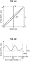
- the sensitivity of the torque sensor 1 is defined by dividing the sensor output V (mV) by the torque T (Nm) applied to the shaft 100 , and expressed as V/T (mV/Nm).
- the angle error in addition to the hysteresis error, the variation of the sensor output in the circumferential direction of the shaft 100 (hereinafter referred to as the angle error) is evaluated.
- the angle error means an error generated when the shaft is rotated.
- the angle error is expressed as (Vmax-Vmin)/Vs (%), where the maximum value of the sensor output is Vmax and the minimum value is Vmin.
- the sum of the hysteresis error and the angle error is referred to as a total error.
- a target value of the total error is not more than 3.0 % .
- chromium steel (SCr 420 ) was used for the shaft member of the shaft 100 , and optimum shot peening conditions was studied.
- the diameter of the shaft 100 was set as 18 mm.
- the shot media was injected while rotating the shaft 100 at a low speed (e.g., 6 rpm).
- FIG. 5 A shows error measuring result when using a steel shot media having the Vickers hardness of 700 (HV) and setting injection pressure as 0.4 MPa and 0.55 MPa.
- the total error is increased to not less than 4 % when using the shot media having the Vickers hardness of 700 (HV).
- the error (hysteresis error and angle error) shown in FIG. 5A represents the maximum value including temperature characteristics (measured under conditions of ambient temperature from - 40 °C to 150 °C).
- the horizontal axis of FIG. 5 A represents the injection time of the shot media, and the injection time of the shot media is represented by dividing the total injection time by the length of the shaft 100 . That is, the injection time of the shot media represents the injection time per 1 cm in the axial direction of the shaft 100 (hereinafter, simply referred to as the injection time).
- FIG. 5 B shows error measuring result when using a steel shot media having the Vickers hardness of 1200 (HV) and setting injection pressure as 0.4 MPa and 0.55 MPa.
- HV Vickers hardness
- the inventors studied the reason why the angle error increases. As the result of studies, the inventors have found that the angle error is largely increased due to Fe 2 B formed on the surface of the shaft member caused by boron included in the shot media.
- the steel shot media having the Vickers hardness of 1200 (HV) is doped with Fe 2 B in order to increase the hardness of the shot media.
- Fe 2 B is formed on the surface of the shaft member when such a shot media is used.
- Fe 2 B is considered to have a large angle error due to the large crystal magnetic anisotropy.
- shot peening is performed by using a shot media having the Vickers hardness of 1200 (HV) and not including (i.e., being free of) boron in the shot peening step in order to reduce the angle error.
- the shot media comprising zirconia (ZrO 2 ) is used.
- the shot media may have the Vickers Hardness of not less than 1100 and not more than 1300 (HV).
- Fe 2 B is not generated on the surface of the shaft member in shot peening by using the zirconia shot media that does not include boron.
- the shot media having high hardness such as Vickers hardness of 1200 (HV) is used, it is possible to suppress the increase in angle error. And thus, both the hysteresis error and the angle error can decrease and the sensor sensitivity can be improved.
- FIG. 6 shows error measuring results when the particle diameter is set as not less than 0.6 mm and not more than 0.8 mm, or not less than 0.4 mm and not more than 0.6 mm, and injection pressure is set as 0.4 MPa or 0.55 MPa.
- the zirconia shot media having the Vickers hardness of 1200 (HV) and setting injection pressure of not less than 0.4 MPa and not more than 0.55 MPa it is preferable to use the shot media having the particle diameter of not less than 0.4 mm and not more than 0.6 mm.
- the total error is minimized when setting the injection pressure of 0.4 MPa and the injection time of 20 sec/cm.
- FIG. 7 shows the error measuring result of ten samples of the shaft 100 that have been prepared under this condition for minimizing the total error. As shown in FIG. 7 , although the total error varies within approximately 0.5 %, each sample indicates the hysteresis of not more than 0.2 % and the angle error of not more than 1.0 %, and thus the total error of not more than 3.0 %. It was confirmed that the target value has been obtained.
- a method for manufacturing a torque sensor 1 comprises a heat treatment step of subjecting an iron-based shaft member to a carburizing, quenching, and tempering process, and a shot peening step of performing shot peening using a steel shot media having a Vickers hardness at least equal to 1100 and at most equal to 1300 and being free of boron, at least in a position on the shaft member, after the heat treatment step, to which the sensor portion 2 is to be attached.
- the non-magnetic retained austenite can decrease only on the surface of the shaft 100 by providing the shot peening step, and thus the deterioration of the toughness of the shaft 100 can be suppressed.
- the hysteresis error can decrease and the sensor sensitivity can be improved by performing the shot peening step with using a shot media having the high hardness of 1200 (HV).
- the angle error may increase due to the influence of boron when using the steel shot media having the Vickers hardness of 1200 (HV), since such a shot media includes boron.
- Fe 2 B is not generated on the surface of the shaft member and thus the angle error can decrease.
Landscapes
- Chemical & Material Sciences (AREA)
- Engineering & Computer Science (AREA)
- Physics & Mathematics (AREA)
- Mechanical Engineering (AREA)
- Organic Chemistry (AREA)
- Crystallography & Structural Chemistry (AREA)
- Materials Engineering (AREA)
- Metallurgy (AREA)
- Thermal Sciences (AREA)
- Electromagnetism (AREA)
- General Physics & Mathematics (AREA)
- Manufacturing & Machinery (AREA)
- Power Steering Mechanism (AREA)
- Heat Treatment Of Articles (AREA)
Abstract
Description
- The present invention relates to a method for manufacturing a magnetostrictive torque sensor shaft.
- Conventionally, a magnetostrictive torque sensor has been known. The magnetostrictive torque sensor uses a shaft having magnetostrictive characteristic whose magnetic permeability changes when stress is applied, and detects a torque applied to the shaft by detecting a change in magnetic permeability of the shaft when the torque is applied and the shaft is twisted as a change in inductance of a detecting coil.
- The citation list information relating to the invention according to the present application includes
Patent Document 1. - Patent Document 1:
JP2018-112451A - It has been known that a steel material used for the shaft comprises a non-magnetic structure called retained austenite. The retained austenite is gamma-iron (γ-Fe) with face-centered cubic lattice structure in which the other elements are dissolved.
- When the shaft includes a large amount of the non-magnetic retained austenite, the change in magnetic permeability when the torque is applied reduces, and thus it leads to decrease in sensitivity of the magnetostrictive torque sensor.
- However, if the amount of the retained austenite in the entire shaft reduces by adjusting the conditions of heat treatment or the like, the toughness of the shaft may decrease, so that the shaft may be cracked.
- In addition, the magnetostrictive torque sensor is used for, e.g., a transmission stroke control or an engine output control. Therefore, it is desirable to have a small error as much as possible to perform a reliable shift transmission.
- Therefore, it is an object of the present invention to provide a method for manufacturing a magnetostrictive torque sensor shaft capable of improving sensor sensitivity and reducing an error while securing toughness.
- For solving the above-mentioned problems, the object of the present invention is to provide a method for manufacturing a magnetostrictive torque sensor shaft to which a sensor portion of the magnetostrictive torque sensor is to be attached, the method comprising heat treatment step of subjecting an iron-based shaft member to a carburizing, quenching, and tempering process, and a shot peening step of performing shot peening using a steel shot media having a Vickers hardness at least equal to 1100 and at most equal to 1300 and being free of boron, at least in a position on the shaft member, after the heat treatment step, to which the sensor portion is to be attached. Advantageous Effects of Invention
- According to the present invention, it is possible to provide a method for manufacturing a magnetostrictive torque sensor shaft capable of improving sensor sensitivity and reducing errors while securing toughness.
-
-
FIG. 1A is a side view showing an example of a sensor portion of a magnetostrictive torque sensor that is attached to a shaft. -
FIG. 1B is a cross-sectional view taken along line A-A inFIG. 1A . -
FIG. 2A is a plan view schematically showing a state in which a bobbin is deployed, which illustrates a first detecting coil and a fourth detecting coil. -
FIG. 2B is a pl3an view schematically showing a state in which the bobbin is deployed, which illustrates a second detecting coil and a third detecting coil. -
FIG. 3 is a circuit diagram showing an example of a measuring part for measuring torque applied to the shaft by detection signal of the torque sensor. -
FIG. 4A is a diagram that illustrates sensitivity and hysteresis error. -
FIG. 4B is a diagram that illustrates an angle error. -
FIG. 5A is a diagram showing a measurement result of an error when a steel shot media having a Vickers hardness of 700 is used. -
FIG. 5B is a diagram showing a measurement result of an error when a steel shot media having a Vickers hardness of 1200 is used. -
FIG. 6 is a diagram showing a measurement result of an error when a zirconia shot media having a Vickers hardness of 1200 is used. -
FIG. 7 is a diagram showing a measurement result of distribution of an error when a zirconia shot media having a Vickers hardness of 1200 is used and a predetermined shot condition is set. - (Embodiments)
- Embodiments of the present invention will be explained in conjunction with appended drawings.
- Firstly, a magnetostrictive torque sensor (hereinafter simply referred to as a torque sensor) will be explained.
FIG. 1A is a side view showing an example of a sensor portion of the torque sensor that is attached to a shaft.FIG. 1B is a cross-sectional view taken along line A-A inFIG. 1A .FIG. 2A is a plan view schematically showing a state in which a bobbin is deployed, which illustrates a first detecting coil and a fourth detecting coil.FIG. 2B is a plan view schematically showing a state in which the bobbin is deployed, which illustrates a second detecting coil and a third detecting coil.FIG. 3 is a circuit diagram showing an example of a measuring part to measure torque applied to the shaft by detection signal of the torque sensor. - As shown in
FIGS. 1A and 1B, thesensor portion 2 of thetorque sensor 1 is attached around a magnetostrictive torque sensor shaft (hereinafter, simply referred to as a shaft) 100 having magnetostrictive characteristics. Thetorque sensor 1 measures torque (rotational torque) applied to theshaft 100. - The
shaft 100 comprises a material having magnetostrictive characteristics (such as SCr420, SCM420, SNCM616, SUS440C, and SUS630), and is formed in a cylindrical shape (rod shape). For example, theshaft 100 is used for torque transmission in a powertrain system of a vehicle or a torque transmission in an engine of a vehicle. - The
sensor portion 2 comprises acoil 21 and amagnetic ring 22. Themagnetic ring 22 comprises a magnetic material (a ferromagnetic material) and is formed in a hollow cylindrical shape. Thecoil 21 is inserted into a hollow portion of themagnetic ring 22. Themagnetic ring 22 serves to suppress leakage of a magnetic flux generated by the detectingcoil 3 of thecoil 21 to the outside, thereby decreasing the sensitivity. - The
coil 21 comprises abobbin 23 comprising a non-magnetic resin, and a plurality of detectingcoils 3 formed by winding insulated wires around an outer periphery of thebobbin 23. Thebobbin 23 is provided coaxially with theshaft 100 in such a manner as to be separated from theshaft 100, and is formed in a hollow cylindrical shape. A plurality of firstinclined grooves 4 inclined at a predetermined angle (herein +45°) with respect to an axial direction of theshaft 100 and a plurality of secondinclined grooves 5 inclined at a predetermined angle (herein -45°) with respect to a direction opposite to the firstinclined grooves 4 along the axial direction are formed on an outer peripheral surface of thebobbin 23. The firstinclined grooves 4 and the secondinclined grooves 5 are formed of grooves concaved in a radial direction of thebobbin 23. - As shown in
FIGS. 2A and 2B, thecoil 21 comprises first to fourth detectingcoils 31 to 34 as the detectingcoils 3. The first detectingcoil 31 and the fourth detectingcoil 34 are formed by winding insulated wires around thebobbin 23 along the firstinclined grooves 4. The second detectingcoil 32 and the third detectingcoil 33 are formed by winding insulated wires around thebobbin 23 along the secondinclined grooves 5. - In
FIG. 2A ,reference signs coil 31, andreference signs coil 34. InFIG. 2B ,reference signs coil 32, andreference signs coil 33. In addition,FIGS. 2A and 2B shows winding of the insulated wires for one turn. Each of the detectingcoils 31 to 34 is formed by repeatedly winding the insulated wires to a target number of turns. In addition, the method for winding the insulated wires shown inFIGS. 2A and 2B is merely an example. The detecting coils 31 to 34 may be formed by using the other methods of winding. - The first detecting
coil 31 and the fourth detectingcoil 34 are provided for detecting a change in magnetic permeability of theshaft 100 in a first direction inclined at a predetermined angle (herein +45°) with respect to the axial direction of theshaft 100. The second detectingcoil 32 and the third detectingcoil 33 are provided for detecting a change in magnetic permeability of theshaft 100 in a second direction inclined at the predetermined angle (herein -45°) opposite to the first direction along the axial direction of theshaft 100. - As shown in
FIG. 3 , a measuringpart 41 measures the torque applied to theshaft 100 by detecting changes in inductance of the first to fourth detectingcoils 31 to 34. - The measuring
part 41 comprises abridge circuit 42 configured by annularly arranging the first detectingcoil 31, the second detectingcoil 32, the fourth detectingcoil 34, and the third detectingcoil 33 in this order, atransmitter 43 for applying alternating current (AC) voltage between a contact point a arranged between the first detectingcoil 31 and the second detectingcoil 32 and a contact point b arranged between the third detectingcoil 33 and the fourth detectingcoil 34, avoltage measuring circuit 44 for detecting voltage between a contact point c arranged between the first detectingcoil 31 and the third detectingcoil 33 and a contact point d arranged between the second detectingcoil 32 and the fourth detectingcoil 34, and atorque calculating part 45 for calculating a torque applied to theshaft 100 based on the voltage measured by thevoltage measuring circuit 44. Thebridge circuit 42 is configured by arranging the first detectingcoil 31 and the fourth detectingcoil 34 at one of two sides facing each other, and arranging the second detectingcoil 32 and the third detectingcoil 33 at the other of the two sides facing each other. - In the measuring
part 41, inductances L1 to L4 of the first to fourth detectingcoil 31 to 34 are equal when the torque is not applied to theshaft 100, and the voltage detected by thevoltage measuring circuit 44 becomes approximately zero. - When the torque is applied to the
shaft 100, the magnetic permeability in the direction of +45° with respect to the axial direction decreases (or increases) while the magnetic permeability in the direction of -45° with respect to the axial direction increases (or decreases). Thus, the inductances in the first detectingcoil 31 and the fourth detectingcoil 34 decrease (or increase) while the inductances in the second detectingcoil 32 and the third detectingcoil 33 increase (or decrease), when the torque is applied to theshaft 100 while the AC voltage is applied from thetransmitter 43. As a result, the voltage detected by thevoltage measuring circuit 44 changes, and thus thetorque calculating part 45 calculates the torque applied to theshaft 100 based on the change in voltage. - Since the first detecting
coil 31 and the fourth detectingcoil 34 have the same structure as the second detectingcoil 32 and the third detectingcoil 33 except the winding direction being different, the effects of the temperature or the like on the inductances of the first to fourth detectingcoils 31 to 34 can be canceled by using thebridge circuit 42 shown inFIG. 3 . And thus, the torque applied to theshaft 100 can be accurately detected. In addition, for thetorque sensor 1, when the inductances in the first detectingcoil 31 and the fourth detectingcoil 34 increase (or decrease), while the inductances in the second detectingcoil 32 and the third detectingcoil 33 decrease (or increase). Thus, the detection sensitivity can be further improved by using thebridge circuit 42 shown inFIG. 3 . - In the present embodiment, an iron-based shaft member subjected to a carburizing, quenching and tempering process, thereafter shot peening, and then surface polishing is used as the
shaft 100. - That is, the method for manufacturing the
shaft 100 according to the present embodiment comprises a heat treatment step of subjecting an iron-based shaft member to a carburizing, quenching, and tempering process, a shot peening step of performing shot peening at least in a position on the shaft member, after the heat treatment step, to which the sensor portion is to be attached, and a surface polishing step of subjecting the shaft member after the shot peening to surface polishing. - For the shaft member used for the
shaft 100, iron-based materials such as SCr420 (chromium steel), SCM420 (chromium-molybdenum steel), SNCM616 (nickel-chromium molybdenum steel), SUS440C (martensitic stainless), SUS630 (precipitation hardening stainless steel), and the like can be used. In the present embodiment, SCr420 is used for the shaft member. - The mechanical strength including the toughness of the
shaft 100 can be enhanced by performing the carburizing, quenching, and tempering process on the entire shaft member. In the present embodiment, surface hardness of the shaft member after the heat treatment step is determined as not less than HV (Vickers hardness) 650. This is because if the surface hardness of the shaft member after the heat treatment step is low, the sensor sensitivity may decrease, or the hysteresis error may increase. The surface hardness of the shaft member after the heat treatment step is preferably at least equal to HV 650 in order to suppress deterioration of the sensor sensitivity and the hysteresis error. That is, in the heat treatment step, it is preferable to perform heat treatment in such a manner that the surface hardness of the shaft member after the heat treatment step is not less than HV 650. In the present embodiment, the heat treatment step is performed by gas carburization (at 920°C for 3 hours, then at 830°C for 15 min, and then oil quenching and tempering at 200°C for 1.5 hours). - The shaft member is crooked when being subjected to the heat treatment step. Thus, it is preferable to perform a step of press-unbending the shaft member and a grinding step of grinding the surface of the shaft member to provide the shaft member with a straight shape, in addition to the heat treatment step. In the grinding step, it is preferable to perform grinding in such a manner that a grinding amount (grinding depth) at the part (referred to as the measuring part), to which the
sensor portion 2 is to be attached, is even in the circumferential direction. This is because that a composition varies along the depth direction (radial direction) of the shaft member, and when the grinding amount (grinding depth) is uneven in the measuring part, portions with different compositions are generated on the surface of the measuring part and may cause the angle errors to be described later. In order to obtain the desired outer diameter after the grinding step, the shaft member before the heat treatment is preferably slightly larger than the finished outer diameter (for example, the shaft member before the heat treatment having a diameter of about 0.2 mm). - In the shot peening step, the shaft member after the heat treatment is subjected to the shot peening. Martensitic transformation (diffusionless transformation) occurs at the surface (a region distant with a predetermined depth from the surface) of the
shaft 100 by shot peening the shaft member after heat treatment, so that non-magnetic retained austenite decreases, and ferromagnetic martensite can increase. As a result, the change in magnetic permeability when the torque is applied increases by reducing the non-magnetic area on the surface of theshaft 100 and increasing the magnetic area on the surface of theshaft 100. And thus, the sensitivity of thetorque sensor 1 can be improved. The retained austenite is iron (γ-Fe) with face-centered cubic lattice structure in which the other elements are dissolved. The martensite is a solid solution in which carbon enters into a crystal of iron with body-centered tetragonal lattice structure. - In addition, the surface of the shaft member is work hardened by shot peening the shaft member after the heat treatment and thus the hysteresis characteristic is improved. More specifically, by shot peening the shaft member after the heat treatment, the magnetic domains (areas in which the direction of the magnetic moment is aligned) on the surface of the
shaft 100 are subdivided, and the retained austenite serving as a pinning site for preventing movement of the magnetic domain wall, which is the boundary of the magnetic domains, is reduced. As a result, when the applied torque is released, the magnetic domains and the magnetic walls will be easily returned to the original state, and thus the hysteresis error decreases. - As shown in
FIG. 4A , the sensitivity of thetorque sensor 1 is defined by dividing the sensor output V (mV) by the torque T (Nm) applied to theshaft 100, and expressed as V/T (mV/Nm). The sensor sensitivity is expressed as (V2-V1)/(T2×T1) = Vs/Ts, where the torque T applied to theshaft 100 is not less than -T1 and not more than +T1, the sensor output corresponding to the torque -T1 is V1, and the sensor output corresponding to the torque +T1 is V2. The hysteresis error, which is also referred to as a linearity error, is a ratio of the maximum value Vh of a sensor output difference at the same torque between the torque increase and the torque decrease with respect to the sensor output Vs (= V2-V1), and is expressed as Vh/Vs (%FS, FS means a full-scale). - In the present embodiment, in addition to the hysteresis error, the variation of the sensor output in the circumferential direction of the shaft 100 (hereinafter referred to as the angle error) is evaluated. As shown in
FIG. 4B , the angle error means an error generated when the shaft is rotated. The angle error is expressed as (Vmax-Vmin)/Vs (%), where the maximum value of the sensor output is Vmax and the minimum value is Vmin. Hereinafter, the sum of the hysteresis error and the angle error is referred to as a total error. In the present embodiment, a target value of the total error is not more than 3.0%. - In the present embodiment, chromium steel (SCr420) was used for the shaft member of the
shaft 100, and optimum shot peening conditions was studied. In the present embodiment, the diameter of theshaft 100 was set as 18 mm. When performing the shot peening, the shot media was injected while rotating theshaft 100 at a low speed (e.g., 6 rpm). - Firstly,
FIG. 5A shows error measuring result when using a steel shot media having the Vickers hardness of 700 (HV) and setting injection pressure as 0.4 MPa and 0.55 MPa. As shown inFIG. 5A , the total error is increased to not less than 4% when using the shot media having the Vickers hardness of 700 (HV). The error (hysteresis error and angle error) shown inFIG. 5A represents the maximum value including temperature characteristics (measured under conditions of ambient temperature from - 40°C to 150°C). The horizontal axis ofFIG. 5A represents the injection time of the shot media, and the injection time of the shot media is represented by dividing the total injection time by the length of theshaft 100. That is, the injection time of the shot media represents the injection time per 1 cm in the axial direction of the shaft 100 (hereinafter, simply referred to as the injection time). - Next,
FIG. 5B shows error measuring result when using a steel shot media having the Vickers hardness of 1200 (HV) and setting injection pressure as 0.4 MPa and 0.55 MPa. As shown inFIG. 5B , when using the shot media having the Vickers hardness of 1200 (HV), the hysteresis error decreases as compared with the case using the shot media having the Vickers hardness of 700 (HV). Meanwhile, the angle error increases. As a result, the total error increases. - As described above, it has been found that the total error cannot be reduced only by increasing the hardness of the shot media. Therefore, the inventors studied the reason why the angle error increases. As the result of studies, the inventors have found that the angle error is largely increased due to Fe2B formed on the surface of the shaft member caused by boron included in the shot media.
- In more detail, the steel shot media having the Vickers hardness of 1200 (HV) is doped with Fe2B in order to increase the hardness of the shot media. Thus, Fe2B is formed on the surface of the shaft member when such a shot media is used. Fe2B is considered to have a large angle error due to the large crystal magnetic anisotropy.
- Thus, in the present embodiment, shot peening is performed by using a shot media having the Vickers hardness of 1200 (HV) and not including (i.e., being free of) boron in the shot peening step in order to reduce the angle error. In more detail, the shot media comprising zirconia (ZrO2) is used. In the meantime, since hardness in the shot media varies, the shot media may have the Vickers Hardness of not less than 1100 and not more than 1300 (HV).
- Further, Fe2B is not generated on the surface of the shaft member in shot peening by using the zirconia shot media that does not include boron. As a result, even though the shot media having high hardness such as Vickers hardness of 1200 (HV) is used, it is possible to suppress the increase in angle error. And thus, both the hysteresis error and the angle error can decrease and the sensor sensitivity can be improved.
- For the case using the zirconia shot media having the Vickers hardness of 1200 (HV), optimum shot peening conditions were studied.
FIG. 6 shows error measuring results when the particle diameter is set as not less than 0.6 mm and not more than 0.8 mm, or not less than 0.4 mm and not more than 0.6 mm, and injection pressure is set as 0.4 MPa or 0.55 MPa. - As shown in
FIG. 6 , when using the zirconia shot media having the Vickers hardness of 1200 (HV) and setting injection pressure of not less than 0.4 MPa and not more than 0.55 MPa, it is preferable to use the shot media having the particle diameter of not less than 0.4 mm and not more than 0.6 mm. In addition, it was understood from the measuring result inFIG. 6 that the total error is minimized when setting the injection pressure of 0.4 MPa and the injection time of 20 sec/cm. -
FIG. 7 shows the error measuring result of ten samples of theshaft 100 that have been prepared under this condition for minimizing the total error. As shown inFIG. 7 , although the total error varies within approximately 0.5 %, each sample indicates the hysteresis of not more than 0.2 % and the angle error of not more than 1.0 %, and thus the total error of not more than 3.0 %. It was confirmed that the target value has been obtained. - As described above, a method for manufacturing a
torque sensor 1 according to the present embodiment comprises a heat treatment step of subjecting an iron-based shaft member to a carburizing, quenching, and tempering process, and a shot peening step of performing shot peening using a steel shot media having a Vickers hardness at least equal to 1100 and at most equal to 1300 and being free of boron, at least in a position on the shaft member, after the heat treatment step, to which thesensor portion 2 is to be attached. - The non-magnetic retained austenite can decrease only on the surface of the
shaft 100 by providing the shot peening step, and thus the deterioration of the toughness of theshaft 100 can be suppressed. The hysteresis error can decrease and the sensor sensitivity can be improved by performing the shot peening step with using a shot media having the high hardness of 1200 (HV). However, the angle error may increase due to the influence of boron when using the steel shot media having the Vickers hardness of 1200 (HV), since such a shot media includes boron. In the present embodiment, by using the shot media free of boron, Fe2B is not generated on the surface of the shaft member and thus the angle error can decrease. As a result, it is possible to obtain thetorque sensor 1 having high sensor sensitivity while securing toughness and having the total error of not more than 3.0%. - Next, the technical concept grasped from the above-described embodiment is described with reference to the signs or the like in the embodiment. However, each reference sign or the like in the following description is not limited to a member or the like specifically showing the elements in the following claims in the embodiment.
- [1] A method for manufacturing a magnetostrictive torque sensor shaft (100) to which a sensor portion (2) of a magnetostrictive torque sensor (1) is to be attached, the method comprising: heat treatment step of subjecting an iron-based shaft member to a carburizing, quenching, and tempering process; and a shot peening step of performing shot peening using a steel shot media having a Vickers hardness at least equal to 1100 and at most equal to 1300 and being free of boron, at least in a position on the shaft member, after the heat treatment step, to which the sensor portion (2) is to be attached.
- [2] The method for manufacturing the magnetostrictive torque sensor shaft according to [1], wherein the shot media comprising zirconia is used.
- [3] The method for manufacturing the magnetostrictive torque sensor shaft according to any one of [1] to [3], wherein the shot media having a particle diameter of not less than 0.6 mm is used, and an injection pressure is not less than 0.4 MPa and not more than 0.55 MPa in the shot peening step.
- [4] The method for manufacturing the magnetostrictive torque sensor shaft according to any one of [1] to [3], wherein the shaft member comprises chromium steel.
- [5] The method for manufacturing the magnetostrictive torque sensor shaft according to any one of [1] to [4], wherein the heat treatment process is performed in such a manner that a surface hardness of the shaft member after the heat treatment process comprises the Vickers hardness of not less than 650 HV.
- Although the embodiments of the invention have been described, the invention according to claims is not to be limited to the embodiments. In addition, please note that all combinations of the features described in the embodiments are not necessary to solve the problem of the invention. Furthermore, the various kinds of modifications can be implemented without departing from the gist of the invention.
- To provide a method for manufacturing a magnetostrictive torque sensor shaft capable of improving sensor sensitivity and reducing an error while securing toughness. Reference Signs List
-
- 1
- TORQUE SENSOR (MAGNETOSTRICTIVE TORQUE SENSOR)
- 2
- SENSOR PORTION
- 3
- DETECTING COIL
- 100
- SHAFT (MAGNETOSTRICTIVE TORQUE SENSOR SHAFT)
Claims (9)
- A method for manufacturing a magnetostrictive torque sensor shaft to which a sensor portion of a magnetostrictive torque sensor is to be attached, the method comprising:heat treatment step of subjecting an iron-based shaft member to a carburizing, quenching, and tempering process; anda shot peening step of performing shot peening using a steel shot media having a Vickers hardness at least equal to 1100 and at most equal to 1300 and being free of boron, at least in a position on the shaft member, after the heat treatment step, to which the sensor portion is to be attached.
- The method for manufacturing the magnetostrictive torque sensor shaft according to claim 1, wherein the shot media comprising zirconia is used.
- The method for manufacturing the magnetostrictive torque sensor shaft according to claim 1 or 2, wherein the shot media having a particle diameter of not less than 0.6 mm is used, and an injection pressure is not less than 0.4 MPa and not more than 0.55 MPa in the shot peening step.
- The method for manufacturing the magnetostrictive torque sensor shaft according to claim 1 or 2, wherein the shaft member comprises chromium steel.
- The method for manufacturing the magnetostrictive torque sensor shaft according to claim 3, wherein the shaft member comprises chromium steel.
- The method for manufacturing the magnetostrictive torque sensor shaft according to claim 1 or 2, wherein the heat treatment process is performed in such a manner that a surface hardness of the shaft member after the heat treatment process comprises the Vickers hardness of not less than 650 HV.
- The method for manufacturing the magnetostrictive torque sensor shaft according to claim 3, wherein the heat treatment process is performed in such a manner that a surface hardness of the shaft member after the heat treatment process comprises the Vickers hardness of not less than 650 HV.
- The method for manufacturing the magnetostrictive torque sensor shaft according to claim 4, wherein the heat treatment process is performed in such a manner that a surface hardness of the shaft member after the heat treatment process comprises the Vickers hardness of not less than 650 HV.
- The method for manufacturing the magnetostrictive torque sensor shaft according to claim 5, wherein the heat treatment process is performed in such a manner that a surface hardness of the shaft member after the heat treatment process comprises the Vickers hardness of not less than 650 HV.
Applications Claiming Priority (2)
| Application Number | Priority Date | Filing Date | Title |
|---|---|---|---|
| JP2018238574A JP7008616B2 (en) | 2018-12-20 | 2018-12-20 | Manufacturing method of shaft for magnetostrictive torque sensor |
| PCT/JP2019/048462 WO2020129770A1 (en) | 2018-12-20 | 2019-12-11 | Method of manufacturing magnetostrictive torque sensor shaft |
Publications (3)
| Publication Number | Publication Date |
|---|---|
| EP3901602A1 true EP3901602A1 (en) | 2021-10-27 |
| EP3901602A4 EP3901602A4 (en) | 2022-09-14 |
| EP3901602B1 EP3901602B1 (en) | 2025-04-23 |
Family
ID=71100436
Family Applications (1)
| Application Number | Title | Priority Date | Filing Date |
|---|---|---|---|
| EP19900001.9A Active EP3901602B1 (en) | 2018-12-20 | 2019-12-11 | Method of manufacturing magnetostrictive torque sensor shaft |
Country Status (5)
| Country | Link |
|---|---|
| US (1) | US12152949B2 (en) |
| EP (1) | EP3901602B1 (en) |
| JP (1) | JP7008616B2 (en) |
| CN (1) | CN113196024A (en) |
| WO (1) | WO2020129770A1 (en) |
Families Citing this family (2)
| Publication number | Priority date | Publication date | Assignee | Title |
|---|---|---|---|---|
| JP7173697B2 (en) * | 2018-12-20 | 2022-11-16 | 日立金属株式会社 | METHOD OF MANUFACTURING SHAFT FOR MAGNETOSTRICTIVE TORQUE SENSOR |
| TWI857618B (en) * | 2023-05-23 | 2024-10-01 | 中國鋼鐵股份有限公司 | Surface strengthening continuous heat treatment method and surface strengthening continuous heat treatment mechanism |
Family Cites Families (25)
| Publication number | Priority date | Publication date | Assignee | Title |
|---|---|---|---|---|
| US1840237A (en) * | 1930-05-26 | 1932-01-05 | Cincinnati Grinders Inc | Work holder for straightening machines |
| US4823620A (en) * | 1986-02-10 | 1989-04-25 | Nissan Motor Company, Ltd. | Magnetostrictive device for measuring torsional torque |
| US5205145A (en) * | 1989-09-25 | 1993-04-27 | Kubota Corporation | Method of producing torque sensor shafts |
| US5280729A (en) * | 1991-04-30 | 1994-01-25 | Nissan Motor Co., Ltd. | Magnetostrictive torque detecting apparatus |
| JP3100433B2 (en) * | 1991-09-06 | 2000-10-16 | 株式会社小松製作所 | Detection shaft for torque sensor and method of manufacturing the same |
| US5409415A (en) * | 1992-07-02 | 1995-04-25 | Nikkato Corp. | Shot method |
| EP0609463B1 (en) * | 1992-08-24 | 1999-11-17 | Kubota Corporation | Method for manufacturing magnetostriction type torque sensor shaft, and the shaft |
| JPH06158158A (en) * | 1992-11-30 | 1994-06-07 | Tougou Seisakusho:Kk | Production of coil spring |
| JP3379824B2 (en) * | 1994-06-14 | 2003-02-24 | 株式会社不二機販 | Method of manufacturing surface hardened metal shot |
| US5526664A (en) * | 1994-09-07 | 1996-06-18 | Progressive Technologies, Inc. | Method of forming a textured pattern on a metal plate which pattern is transformed to a plastic part, and a press plate and plastic part produced thereby |
| EP0803582B1 (en) * | 1996-04-26 | 2002-06-19 | Denso Corporation | Method of stress inducing transformation of austenite stainless steel and method of producing composite magnetic members |
| JPH1029160A (en) * | 1996-07-12 | 1998-02-03 | Sintokogio Ltd | Shot-peening method for high hardness metal products and high hardness metal products |
| JP3246657B2 (en) * | 1998-01-14 | 2002-01-15 | 日産自動車株式会社 | Manufacturing method of high surface pressure member |
| JP2002036115A (en) * | 2000-07-31 | 2002-02-05 | Sintokogio Ltd | Shot-pinning processing method and article to be processed |
| JP2002340701A (en) * | 2001-05-18 | 2002-11-27 | Hitachi Metals Ltd | Method for manufacturing magnetostrictive torque sensor shaft |
| JP2004037240A (en) * | 2002-07-03 | 2004-02-05 | Suzuki Motor Corp | Magnetostrictive torque sensor shaft and method of manufacturing the same |
| EP1516940B1 (en) | 2003-09-18 | 2010-09-15 | Mahindra & Mahindra Ltd. | Method for producing gears and/or shaft components with superior bending fatigue strength and pitting fatigue life from conventional alloy steel |
| KR100828250B1 (en) * | 2004-03-26 | 2008-05-07 | 캐논 가부시끼가이샤 | Electrophotography photosensitive body, method for producing electrophotography photosensitive body, process cartridge and electrophotograph |
| US8332998B2 (en) * | 2005-08-25 | 2012-12-18 | Sintokogio, Ltd. | Shot-peening process |
| JP4895108B2 (en) | 2006-09-15 | 2012-03-14 | 日産自動車株式会社 | FeGaAl alloy and magnetostrictive torque sensor |
| JP5164539B2 (en) * | 2007-11-28 | 2013-03-21 | 大同特殊鋼株式会社 | Shot peening method |
| JP6301125B2 (en) * | 2013-12-17 | 2018-03-28 | Ntn株式会社 | In-wheel motor drive device |
| JP6333579B2 (en) * | 2014-03-04 | 2018-05-30 | Ntn株式会社 | In-wheel motor drive device |
| JP6661502B2 (en) * | 2016-09-23 | 2020-03-11 | 本田技研工業株式会社 | Magnetostrictive torque sensor and method of manufacturing magnetostrictive torque sensor |
| JP6740908B2 (en) * | 2017-01-11 | 2020-08-19 | 日立金属株式会社 | Method for manufacturing shaft for magnetostrictive torque sensor |
-
2018
- 2018-12-20 JP JP2018238574A patent/JP7008616B2/en active Active
-
2019
- 2019-12-11 CN CN201980084090.8A patent/CN113196024A/en active Pending
- 2019-12-11 EP EP19900001.9A patent/EP3901602B1/en active Active
- 2019-12-11 US US17/416,850 patent/US12152949B2/en active Active
- 2019-12-11 WO PCT/JP2019/048462 patent/WO2020129770A1/en not_active Ceased
Also Published As
| Publication number | Publication date |
|---|---|
| JP2020101404A (en) | 2020-07-02 |
| EP3901602B1 (en) | 2025-04-23 |
| WO2020129770A1 (en) | 2020-06-25 |
| US20220026294A1 (en) | 2022-01-27 |
| EP3901602A4 (en) | 2022-09-14 |
| US12152949B2 (en) | 2024-11-26 |
| JP7008616B2 (en) | 2022-01-25 |
| CN113196024A (en) | 2021-07-30 |
Similar Documents
| Publication | Publication Date | Title |
|---|---|---|
| CN108303203B (en) | Method for manufacturing shaft for magnetostrictive torque sensor | |
| KR920006454B1 (en) | Magnetic elastic torque transducer, manufacturing method thereof and torque detecting method | |
| KR100365836B1 (en) | Collarless circularly magnetized torque transducer and method for measuring torque using same | |
| JP6242412B2 (en) | Redundant torque sensor-multiband array | |
| Kobayashi et al. | Evaluation of case depth in induction-hardened steels: Magnetic hysteresis measurements and hardness-depth profiling by differential permeability analysis | |
| JP2004037240A (en) | Magnetostrictive torque sensor shaft and method of manufacturing the same | |
| EP3901602B1 (en) | Method of manufacturing magnetostrictive torque sensor shaft | |
| US11346731B2 (en) | Detection circuit and detection method for magnetostrictive torque sensor | |
| CN105683603A (en) | Steel bearing assembly with magnetic pattern | |
| US11732318B2 (en) | Method for manufacturing magnetostrictive torque sensor shaft | |
| Serbin et al. | On the possibility of evaluating magnetostriction characteristics of bulk ferromagnets based on their magnetic properties | |
| Gorkunov et al. | The influence of elastic deformations on the hysteresis properties of a two-layer ferromagnet composed of components with magnetostrictions of opposite signs | |
| JP6880469B2 (en) | Manufacturing method of shaft for magnetostrictive torque sensor | |
| JP4876393B2 (en) | Torque detection device | |
| JP4919013B2 (en) | Magnetostrictive ring and magnetostrictive ring type torque sensor | |
| JP2005008971A (en) | Martensitic stainless steel for torque sensor shaft | |
| US20180149529A1 (en) | Arrangement and use of a workpiece made of steel for measuring a force or a torque | |
| Nonomura et al. | Effect of excitation magnetic field on characteristics of magnetostrictive torque sensors | |
| JPH0290030A (en) | Detecting device for torque |
Legal Events
| Date | Code | Title | Description |
|---|---|---|---|
| STAA | Information on the status of an ep patent application or granted ep patent |
Free format text: STATUS: THE INTERNATIONAL PUBLICATION HAS BEEN MADE |
|
| PUAI | Public reference made under article 153(3) epc to a published international application that has entered the european phase |
Free format text: ORIGINAL CODE: 0009012 |
|
| STAA | Information on the status of an ep patent application or granted ep patent |
Free format text: STATUS: REQUEST FOR EXAMINATION WAS MADE |
|
| 17P | Request for examination filed |
Effective date: 20210618 |
|
| AK | Designated contracting states |
Kind code of ref document: A1 Designated state(s): AL AT BE BG CH CY CZ DE DK EE ES FI FR GB GR HR HU IE IS IT LI LT LU LV MC MK MT NL NO PL PT RO RS SE SI SK SM TR |
|
| DAV | Request for validation of the european patent (deleted) | ||
| DAX | Request for extension of the european patent (deleted) | ||
| A4 | Supplementary search report drawn up and despatched |
Effective date: 20220817 |
|
| RIC1 | Information provided on ipc code assigned before grant |
Ipc: G01L 3/10 20060101AFI20220810BHEP |
|
| GRAP | Despatch of communication of intention to grant a patent |
Free format text: ORIGINAL CODE: EPIDOSNIGR1 |
|
| STAA | Information on the status of an ep patent application or granted ep patent |
Free format text: STATUS: GRANT OF PATENT IS INTENDED |
|
| INTG | Intention to grant announced |
Effective date: 20241115 |
|
| GRAS | Grant fee paid |
Free format text: ORIGINAL CODE: EPIDOSNIGR3 |
|
| GRAA | (expected) grant |
Free format text: ORIGINAL CODE: 0009210 |
|
| STAA | Information on the status of an ep patent application or granted ep patent |
Free format text: STATUS: THE PATENT HAS BEEN GRANTED |
|
| AK | Designated contracting states |
Kind code of ref document: B1 Designated state(s): AL AT BE BG CH CY CZ DE DK EE ES FI FR GB GR HR HU IE IS IT LI LT LU LV MC MK MT NL NO PL PT RO RS SE SI SK SM TR |
|
| REG | Reference to a national code |
Ref country code: GB Ref legal event code: FG4D |
|
| REG | Reference to a national code |
Ref country code: CH Ref legal event code: EP |
|
| REG | Reference to a national code |
Ref country code: DE Ref legal event code: R096 Ref document number: 602019069164 Country of ref document: DE |
|
| REG | Reference to a national code |
Ref country code: IE Ref legal event code: FG4D |
|
| REG | Reference to a national code |
Ref country code: NL Ref legal event code: MP Effective date: 20250423 |
|
| PG25 | Lapsed in a contracting state [announced via postgrant information from national office to epo] |
Ref country code: NL Free format text: LAPSE BECAUSE OF FAILURE TO SUBMIT A TRANSLATION OF THE DESCRIPTION OR TO PAY THE FEE WITHIN THE PRESCRIBED TIME-LIMIT Effective date: 20250423 |
|
| REG | Reference to a national code |
Ref country code: AT Ref legal event code: MK05 Ref document number: 1788159 Country of ref document: AT Kind code of ref document: T Effective date: 20250423 |
|
| PG25 | Lapsed in a contracting state [announced via postgrant information from national office to epo] |
Ref country code: PT Free format text: LAPSE BECAUSE OF FAILURE TO SUBMIT A TRANSLATION OF THE DESCRIPTION OR TO PAY THE FEE WITHIN THE PRESCRIBED TIME-LIMIT Effective date: 20250825 Ref country code: ES Free format text: LAPSE BECAUSE OF FAILURE TO SUBMIT A TRANSLATION OF THE DESCRIPTION OR TO PAY THE FEE WITHIN THE PRESCRIBED TIME-LIMIT Effective date: 20250423 Ref country code: FI Free format text: LAPSE BECAUSE OF FAILURE TO SUBMIT A TRANSLATION OF THE DESCRIPTION OR TO PAY THE FEE WITHIN THE PRESCRIBED TIME-LIMIT Effective date: 20250423 |
|
| REG | Reference to a national code |
Ref country code: LT Ref legal event code: MG9D |
|
| PG25 | Lapsed in a contracting state [announced via postgrant information from national office to epo] |
Ref country code: NO Free format text: LAPSE BECAUSE OF FAILURE TO SUBMIT A TRANSLATION OF THE DESCRIPTION OR TO PAY THE FEE WITHIN THE PRESCRIBED TIME-LIMIT Effective date: 20250723 Ref country code: GR Free format text: LAPSE BECAUSE OF FAILURE TO SUBMIT A TRANSLATION OF THE DESCRIPTION OR TO PAY THE FEE WITHIN THE PRESCRIBED TIME-LIMIT Effective date: 20250724 |
|
| PG25 | Lapsed in a contracting state [announced via postgrant information from national office to epo] |
Ref country code: PL Free format text: LAPSE BECAUSE OF FAILURE TO SUBMIT A TRANSLATION OF THE DESCRIPTION OR TO PAY THE FEE WITHIN THE PRESCRIBED TIME-LIMIT Effective date: 20250423 |
|
| PG25 | Lapsed in a contracting state [announced via postgrant information from national office to epo] |
Ref country code: BG Free format text: LAPSE BECAUSE OF FAILURE TO SUBMIT A TRANSLATION OF THE DESCRIPTION OR TO PAY THE FEE WITHIN THE PRESCRIBED TIME-LIMIT Effective date: 20250423 |
|
| PG25 | Lapsed in a contracting state [announced via postgrant information from national office to epo] |
Ref country code: HR Free format text: LAPSE BECAUSE OF FAILURE TO SUBMIT A TRANSLATION OF THE DESCRIPTION OR TO PAY THE FEE WITHIN THE PRESCRIBED TIME-LIMIT Effective date: 20250423 |
|
| PG25 | Lapsed in a contracting state [announced via postgrant information from national office to epo] |
Ref country code: AT Free format text: LAPSE BECAUSE OF FAILURE TO SUBMIT A TRANSLATION OF THE DESCRIPTION OR TO PAY THE FEE WITHIN THE PRESCRIBED TIME-LIMIT Effective date: 20250423 |
|
| PG25 | Lapsed in a contracting state [announced via postgrant information from national office to epo] |
Ref country code: RS Free format text: LAPSE BECAUSE OF FAILURE TO SUBMIT A TRANSLATION OF THE DESCRIPTION OR TO PAY THE FEE WITHIN THE PRESCRIBED TIME-LIMIT Effective date: 20250723 |
|
| PG25 | Lapsed in a contracting state [announced via postgrant information from national office to epo] |
Ref country code: IS Free format text: LAPSE BECAUSE OF FAILURE TO SUBMIT A TRANSLATION OF THE DESCRIPTION OR TO PAY THE FEE WITHIN THE PRESCRIBED TIME-LIMIT Effective date: 20250823 |
|
| PG25 | Lapsed in a contracting state [announced via postgrant information from national office to epo] |
Ref country code: LV Free format text: LAPSE BECAUSE OF FAILURE TO SUBMIT A TRANSLATION OF THE DESCRIPTION OR TO PAY THE FEE WITHIN THE PRESCRIBED TIME-LIMIT Effective date: 20250423 |
|
| PG25 | Lapsed in a contracting state [announced via postgrant information from national office to epo] |
Ref country code: DK Free format text: LAPSE BECAUSE OF FAILURE TO SUBMIT A TRANSLATION OF THE DESCRIPTION OR TO PAY THE FEE WITHIN THE PRESCRIBED TIME-LIMIT Effective date: 20250423 Ref country code: SM Free format text: LAPSE BECAUSE OF FAILURE TO SUBMIT A TRANSLATION OF THE DESCRIPTION OR TO PAY THE FEE WITHIN THE PRESCRIBED TIME-LIMIT Effective date: 20250423 |
|
| PG25 | Lapsed in a contracting state [announced via postgrant information from national office to epo] |
Ref country code: CZ Free format text: LAPSE BECAUSE OF FAILURE TO SUBMIT A TRANSLATION OF THE DESCRIPTION OR TO PAY THE FEE WITHIN THE PRESCRIBED TIME-LIMIT Effective date: 20250423 |
|
| PG25 | Lapsed in a contracting state [announced via postgrant information from national office to epo] |
Ref country code: EE Free format text: LAPSE BECAUSE OF FAILURE TO SUBMIT A TRANSLATION OF THE DESCRIPTION OR TO PAY THE FEE WITHIN THE PRESCRIBED TIME-LIMIT Effective date: 20250423 |
|
| REG | Reference to a national code |
Ref country code: DE Ref legal event code: R097 Ref document number: 602019069164 Country of ref document: DE |
|
| PG25 | Lapsed in a contracting state [announced via postgrant information from national office to epo] |
Ref country code: SK Free format text: LAPSE BECAUSE OF FAILURE TO SUBMIT A TRANSLATION OF THE DESCRIPTION OR TO PAY THE FEE WITHIN THE PRESCRIBED TIME-LIMIT Effective date: 20250423 Ref country code: RO Free format text: LAPSE BECAUSE OF FAILURE TO SUBMIT A TRANSLATION OF THE DESCRIPTION OR TO PAY THE FEE WITHIN THE PRESCRIBED TIME-LIMIT Effective date: 20250423 |
|
| PG25 | Lapsed in a contracting state [announced via postgrant information from national office to epo] |
Ref country code: IT Free format text: LAPSE BECAUSE OF FAILURE TO SUBMIT A TRANSLATION OF THE DESCRIPTION OR TO PAY THE FEE WITHIN THE PRESCRIBED TIME-LIMIT Effective date: 20250423 |
|
| PLBE | No opposition filed within time limit |
Free format text: ORIGINAL CODE: 0009261 |
|
| STAA | Information on the status of an ep patent application or granted ep patent |
Free format text: STATUS: NO OPPOSITION FILED WITHIN TIME LIMIT |
|
| REG | Reference to a national code |
Ref country code: CH Ref legal event code: L10 Free format text: ST27 STATUS EVENT CODE: U-0-0-L10-L00 (AS PROVIDED BY THE NATIONAL OFFICE) Effective date: 20260304 |
|
| 26N | No opposition filed |
Effective date: 20260126 |