EP3901562A1 - Method for the compensation of measurement error of a coordinate measuring machine and a measuring machine using said method - Google Patents
Method for the compensation of measurement error of a coordinate measuring machine and a measuring machine using said method Download PDFInfo
- Publication number
- EP3901562A1 EP3901562A1 EP20171027.4A EP20171027A EP3901562A1 EP 3901562 A1 EP3901562 A1 EP 3901562A1 EP 20171027 A EP20171027 A EP 20171027A EP 3901562 A1 EP3901562 A1 EP 3901562A1
- Authority
- EP
- European Patent Office
- Prior art keywords
- signal
- probe
- state observer
- measuring machine
- stylus
- Prior art date
- Legal status (The legal status is an assumption and is not a legal conclusion. Google has not performed a legal analysis and makes no representation as to the accuracy of the status listed.)
- Granted
Links
Images


Classifications
-
- G—PHYSICS
- G01—MEASURING; TESTING
- G01B—MEASURING LENGTH, THICKNESS OR SIMILAR LINEAR DIMENSIONS; MEASURING ANGLES; MEASURING AREAS; MEASURING IRREGULARITIES OF SURFACES OR CONTOURS
- G01B21/00—Measuring arrangements or details thereof, where the measuring technique is not covered by the other groups of this subclass, unspecified or not relevant
- G01B21/02—Measuring arrangements or details thereof, where the measuring technique is not covered by the other groups of this subclass, unspecified or not relevant for measuring length, width, or thickness
- G01B21/04—Measuring arrangements or details thereof, where the measuring technique is not covered by the other groups of this subclass, unspecified or not relevant for measuring length, width, or thickness by measuring coordinates of points
- G01B21/045—Correction of measurements
-
- G—PHYSICS
- G01—MEASURING; TESTING
- G01B—MEASURING LENGTH, THICKNESS OR SIMILAR LINEAR DIMENSIONS; MEASURING ANGLES; MEASURING AREAS; MEASURING IRREGULARITIES OF SURFACES OR CONTOURS
- G01B5/00—Measuring arrangements characterised by the use of mechanical techniques
- G01B5/0011—Arrangements for eliminating or compensation of measuring errors due to temperature or weight
- G01B5/0016—Arrangements for eliminating or compensation of measuring errors due to temperature or weight due to weight
Definitions
- the present invention relates to a method for the compensation of measurement errors of a coordinate measuring machine and a measuring machine using said method.
- coordinate measuring machines comprise members movable along coordinate axes in order to move a probe in a measuring volume.
- the probe comprises a first body configured to be fixed to a chuck of the measuring machine and a mobile part provided with an elongated stylus having one or more measuring tips configured to interact with the workpiece.
- the mobile part comprises a second body, from which the stylus extends and which is connected to the first body by elastic elements that allow limited relative displacement following contact of the tip of the stylus with the workpiece.
- Said relative displacement is detected by a sensor forming part of a detection circuit connected to a control unit of the machine and configured to generate enabling signals for storage of the coordinates of the point of contact between the probe's tip and the workpiece, calculated as a function of the position of the machine axes and the relative displacement or deflection of the probe.
- the stylus may be subjected to mechanical vibrations due to the contact forces exchanged with the workpiece and the finite stiffness of the stylus itself.
- the vibrations of the stylus affect the relative position of the tip with respect to the second body, causing a deterioration in measurement accuracy.
- One method commonly used to limit the negative effects of the mechanical vibrations of the stylus on measurement accuracy is to filter the measurement signals by means of a low-pass filter. This method has the drawback of reducing the measurement bandwidth, reducing the amount of acquirable information in a given time interval and therefore limiting the speed of scanning of the workpiece and/or the density of acquired measurement points.
- the object of the present invention is to overcome, at least in part, the drawbacks of the known art.
- a method for the compensation of measurement errors of a measuring machine comprising a mobile unit and a probe configured to be moved by the mobile unit in a measuring volume, wherein the probe comprises a first body configured to be fixed to the mobile unit and a mobile part comprising a second body, which is attached to the first body and is movable with respect to the first body, and a stylus having at least one tip at one end configured to cooperate with a workpiece; the method comprising the steps of:
- the present method it is possible to compensate for measurement errors due to the mechanical vibrations of the stylus, maintaining high measurement bandwidth and thus allowing a high scanning speed and/or high density of acquired measurement points.
- the method comprises the step of acquiring a third signal related to the acceleration of the second body; the observer receiving the third signal as an input.
- the observer is an optimal observer, preferably a Kalman filter.
- a further object of the present invention is to provide a measuring machine that mitigates, at least in part, the drawbacks of the known art.
- a measuring machine that comprises:
- the measuring machine it is possible to carry out fast and accurate measurements, compensating for measurement errors due to deformation of the stylus.
- the machine comprises a third sensor configured to generate a third signal related to the acceleration of the second body; the state observer receives the third signal as input.
- reference numeral 1 indicates, as a whole, a coordinate-type measuring machine used for taking precision measurements of an object to be measured.
- the measuring machine 1 comprises a bench 2 equipped with a flat, horizontal, top surface 3, or reference plane.
- the measuring machine 1 also comprises a motorised first carriage 5 that slides on the bench 2 along a first horizontal axis (Y-axis) of an X-Y-Z Cartesian reference system of the measuring volume.
- the first carriage 5 has a gantry-type structure and comprises two vertical uprights 6, 7 and an upper horizontal crossbeam 8 that extends between the upper ends of the uprights 6, 7.
- upright 6 comprises a slide 9 sliding on guides (not shown) parallel to the Y-axis and provided, in a known manner, close to a longitudinal edge of the bench 2.
- the crossbeam 8 carries a second carriage 11 configured to slide along the former on guides (not shown) in a direction parallel to a second axis (X-axis) of the reference system.
- the second carriage 11 carries a mobile unit 12 having a vertical axis, movable along its axis parallel to a third axis (Z-axis) of the reference system.
- the mobile unit 12 is configured to carry a probe 13 at the bottom.
- the probe 13 comprises a body 14 with a vertical axis A1 configured to be fixed to the mobile unit 12 ( Figure 1 ) and a mobile part 15 comprising a body 16 having a vertical axis A2, which is attached to body 14 and is movable with respect to body 14, and a stylus 18 having at least one spherical tip 19 with centre C at one end configured to cooperate with a workpiece 20.
- Figure 2 is a one-dimensional schematization, in which body 16 is attached to body 14 by an elastic assembly 17, which is represented by a single spring with stiffness K1 configured to act solely along the X-axis.
- body 16 is attached to body 14 by three elastic elements, each of which is configured to act along a respective X-Y-Z coordinate axis.
- the stylus 18 has a finite flexural stiffness, the component of which in the direction of the X-axis, referring to the one-dimensional schematization Figure 2 , is indicated by K2.
- the stylus 18 has flexural stiffness both in the direction of the X-axis and in the direction of the Y-axis.
- the position of axis A1 of body 14 along the X-axis is indicated by P1.
- the position of axis A2 of body 16 along the X-axis is indicated by P0.
- the position of the centre C of the tip 19 along the X-axis is indicated by P2.
- the probe 13 is subjected to vibrations caused by the interaction of the probe 13 with the workpiece 20 and by the acceleration to which the probe 13 is subjected. These vibrations are dynamic phenomena such that the position of the tip 19 changes continuously with time.
- the measuring machine 1 comprises:
- state observer means a filter configured to receive signals related to variables measured by a system, use a model of the system, and provide an estimate of the state of the system in real time and in a continuous manner.
- the measuring machine 1 comprises a sensor 26 configured to acquire a value of the acceleration P ⁇ 0 of body 16 and generate a third signal related thereto (this also indicated by P ⁇ 0 ).
- the state observer 25 also receives the third signal P ⁇ 0 as input.
- sensor 21 is an accelerometer integral with body 14.
- sensor 21 is constituted by a processing unit that acquires a signal related to the position P1 of body 14 and calculates the acceleration P ⁇ 1 via double differentiation of said signal.
- Sensor 26 is an accelerometer integral with body 16.
- Sensor 22 can be an LVDT associated with the extension of the spring 17.
- Figure 3 shows a one-dimensional model of the probe 13, used by the state observer 25 to estimate the deformation of the probe 13, wherein body 14 is fixed, body 16 can move along the X-axis, and the stylus 18 ( Figure 2 ) can flex, causing displacement of the position of the centre C of the tip 19 along the X-axis.
- m, P ⁇ 1 and a 0 n are considered outputs of respective low-pass filters.
- the frequency bands of m, P ⁇ 1 and a 0 n are limited.
- equations [8], [9] and [10] are first order.
- the diagram of Figure 4 explains equation [9] in relation to P ⁇ 1 .
- Equations [5, 8, 9, 10, 11] are grouped in a single differential matrix equation for the model.
- Equations [6, 12, 13] are grouped in a single matrix equation for the output of the state observer 25.
- the representation of the above-described model is known as a state variable system. From this representation, it is possible to synthetize the state observer 25, which provides an estimate of the real measurement m.
- the synthesis of the state observer 25 can be performed in accordance with known theories, for example, as described by D. Simon in “Optimal state estimation: Kalman, H ⁇ , and nonlinear approaches", John Wiley & Sons, Inc., 2006 .
- the state observer 25 is an optimal observer, preferably a Kalman filter.
- the state observer 25 is synthetized via an H ⁇ technique.
- the state observer 25 is a deterministic observer synthetized via the pole-placement technique.
- control unit 24 comprises, in a manner in itself known, a first compensation function of the quasi-static component of the measurement error due to deflection of the stylus 18 in contact with the workpiece 20. Furthermore, the control unit 24 comprises, in a manner in itself known, a second compensation function of the quasi-static component of the measurement error due to the quasi-constant acceleration of body 14.
- the quasi-static components of the model state estimated by the state observer 25 are cut off by an action of manual modification to the parameter of the synthetized observer, so as to consider only the dynamic state component estimated by the state observer 25.
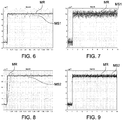
- Figures 6-9 show responses in the estimated measurement MS1, MS2 by the state observer 25 to a step MR of 10 ⁇ m in the real measurement m.
- Figures 7 and 9 are respective enlargements of Figures 6 and 8 in the area of said step.
- the variances in noise v and w can be manually changed, so as to differently weigh the signals P ⁇ 1, P0-P1 and P ⁇ 0 coming from sensors 21, 22 and 26, respectively.
- the variance in noise w a 0 n is set relatively low before Kalman filter synthesis.
- the response of the estimated measurement MS1 is relatively quick, but subject to a lot of noise.
- the variance in noise w a 0 n is set relatively high.
- the response of the estimated measurement MS2 is relatively slow, but subject to less nose with respect to the response of the estimated measurement MS1.
- equation [5] is returned to.
- each of the coefficients M0, K1 and K2 of equations [16] vary with time, as they are obtained via a formula that contains n, and n is a function of time.
- the 3D model is converted into a one-dimensional model again. Therefore, the above-described method can be applied.
- the main difference of the model obtained starting from the three-dimensional formulation of the system's state equations lies in the fact that the constants of the model K1, K2 and M0 vary over time.
- the constants K1, K2 and M0 vary slowly with respect to the dynamics of the system, at each time frame, once the specific values of the system's constants K1, K2 and M0, and consequently of the matrices A, B and C, are assigned, the Kalman filter is synthetized as if the system was invariant over time.
Landscapes
- Physics & Mathematics (AREA)
- General Physics & Mathematics (AREA)
- A Measuring Device Byusing Mechanical Method (AREA)
- Length Measuring Devices With Unspecified Measuring Means (AREA)
Abstract
Description
- The present invention relates to a method for the compensation of measurement errors of a coordinate measuring machine and a measuring machine using said method.
- As is known, coordinate measuring machines comprise members movable along coordinate axes in order to move a probe in a measuring volume. In greater detail, the probe comprises a first body configured to be fixed to a chuck of the measuring machine and a mobile part provided with an elongated stylus having one or more measuring tips configured to interact with the workpiece. The mobile part comprises a second body, from which the stylus extends and which is connected to the first body by elastic elements that allow limited relative displacement following contact of the tip of the stylus with the workpiece. Said relative displacement is detected by a sensor forming part of a detection circuit connected to a control unit of the machine and configured to generate enabling signals for storage of the coordinates of the point of contact between the probe's tip and the workpiece, calculated as a function of the position of the machine axes and the relative displacement or deflection of the probe.
- During the operations of scanning of a workpiece, the stylus may be subjected to mechanical vibrations due to the contact forces exchanged with the workpiece and the finite stiffness of the stylus itself. In particular, the vibrations of the stylus affect the relative position of the tip with respect to the second body, causing a deterioration in measurement accuracy.
- One method commonly used to limit the negative effects of the mechanical vibrations of the stylus on measurement accuracy is to filter the measurement signals by means of a low-pass filter. This method has the drawback of reducing the measurement bandwidth, reducing the amount of acquirable information in a given time interval and therefore limiting the speed of scanning of the workpiece and/or the density of acquired measurement points.
- The object of the present invention is to overcome, at least in part, the drawbacks of the known art.
- According to the present invention, a method is provided for the compensation of measurement errors of a measuring machine comprising a mobile unit and a probe configured to be moved by the mobile unit in a measuring volume, wherein the probe comprises a first body configured to be fixed to the mobile unit and a mobile part comprising a second body, which is attached to the first body and is movable with respect to the first body, and a stylus having at least one tip at one end configured to cooperate with a workpiece; the method comprising the steps of:
- providing a mathematical model of the probe;
- acquiring a first signal related to the acceleration of the first body;
- acquiring a second signal related to the relative displacement between the first and second bodies; and
- estimating deformation of the probe by means of a state observer, which uses said mathematical model and receives as input the first signal and the second signal.
- Thanks to the present method, it is possible to compensate for measurement errors due to the mechanical vibrations of the stylus, maintaining high measurement bandwidth and thus allowing a high scanning speed and/or high density of acquired measurement points.
- Preferably, the method comprises the step of acquiring a third signal related to the acceleration of the second body; the observer receiving the third signal as an input.
- In particular, the observer is an optimal observer, preferably a Kalman filter.
- In this way, it is possible to estimate the deformation of the stylus, i.e. compensate for the measurement error, in an optimal manner.
- A further object of the present invention is to provide a measuring machine that mitigates, at least in part, the drawbacks of the known art.
- According to the present invention, is provided a measuring machine that comprises:
- a mobile unit;
- a probe configured to be moved by the mobile unit in a measuring volume, wherein the probe comprises a first body configured to be fixed to the mobile unit and a mobile part comprising a second body, which is attached to the first body and is movable with respect to the first body, and a stylus having at least one tip at one end configured to cooperate with a workpiece;
- a first sensor configured to generate a first signal related to the acceleration of the first body;
- a second sensor configured to generate a second signal related to the relative displacement between the first and second bodies;
- a memory containing a mathematical model of the probe; and
- a control unit configured to estimate a deformation of the probe) by means of a state observer, which uses said mathematical model and receives as input the first signal and the second signal.
- Thanks to the measuring machine according to the present invention, it is possible to carry out fast and accurate measurements, compensating for measurement errors due to deformation of the stylus.
- In particular, the machine comprises a third sensor configured to generate a third signal related to the acceleration of the second body; the state observer receives the third signal as input.
- In particular, it is possible to increase measurement accuracy by estimating the deflection of the stylus by means of an optimal observer, preferably by means of a Kalman filter.
- Further characteristics and advantages of the present invention will become apparent from the description that follows of a non-limitative embodiment, with reference to the accompanying figures, wherein:
-
Figure 1 is a perspective view of a measuring machine made according to the present invention; -
Figure 2 is a schematic representation of a probe of the measuring machine ofFigure 1 ; -
Figure 3 is a schematic model of the probe ofFigure 2 ; -
Figure 4 is a block diagram of a generic low-pass filter of the model of the probe for narrow-band noise modelling; -
Figure 5 is a block diagram of the system comprising the probe ofFigure 2 and a state observer; and -
Figures 6, 7, 8 and 9 are comparative graphs that show the response to a step in the measurement estimated by a state observer in respective operating configurations. - Referring to
Figure 1 ,reference numeral 1 indicates, as a whole, a coordinate-type measuring machine used for taking precision measurements of an object to be measured. - The
measuring machine 1 comprises abench 2 equipped with a flat, horizontal,top surface 3, or reference plane. Themeasuring machine 1 also comprises a motorisedfirst carriage 5 that slides on thebench 2 along a first horizontal axis (Y-axis) of an X-Y-Z Cartesian reference system of the measuring volume. - The
first carriage 5 has a gantry-type structure and comprises twovertical uprights horizontal crossbeam 8 that extends between the upper ends of theuprights - At the bottom, upright 6 comprises a
slide 9 sliding on guides (not shown) parallel to the Y-axis and provided, in a known manner, close to a longitudinal edge of thebench 2. - The
crossbeam 8 carries asecond carriage 11 configured to slide along the former on guides (not shown) in a direction parallel to a second axis (X-axis) of the reference system. - The
second carriage 11 carries amobile unit 12 having a vertical axis, movable along its axis parallel to a third axis (Z-axis) of the reference system. Themobile unit 12 is configured to carry aprobe 13 at the bottom. - With reference to
Figure 2 , theprobe 13 comprises abody 14 with a vertical axis A1 configured to be fixed to the mobile unit 12 (Figure 1 ) and amobile part 15 comprising abody 16 having a vertical axis A2, which is attached tobody 14 and is movable with respect tobody 14, and astylus 18 having at least onespherical tip 19 with centre C at one end configured to cooperate with aworkpiece 20.Figure 2 is a one-dimensional schematization, in whichbody 16 is attached tobody 14 by anelastic assembly 17, which is represented by a single spring with stiffness K1 configured to act solely along the X-axis. - In reality,
body 16 is attached tobody 14 by three elastic elements, each of which is configured to act along a respective X-Y-Z coordinate axis. - The
stylus 18 has a finite flexural stiffness, the component of which in the direction of the X-axis, referring to the one-dimensional schematizationFigure 2 , is indicated by K2. - In reality, the
stylus 18 has flexural stiffness both in the direction of the X-axis and in the direction of the Y-axis. - In the case described and illustrated herein, the position of axis A1 of
body 14 along the X-axis is indicated by P1. The position of axis A2 ofbody 16 along the X-axis is indicated by P0. The position of the centre C of thetip 19 along the X-axis is indicated by P2. - In the case of not making contact with the
workpiece 20, thespring 17 keepsbody 16 in a rest position where P0 coincides with P1 and the deflection of thestylus 18 is null. Therefore, also P2 coincides with P0 and P1. - If the
tip 19 is in contact with theworkpiece 20,body 16 moves along the X-axis with respect tobody 14 and thestylus 18 deflects. In this configuration, P0, P1 and P2 do not coincide. - For the sake of clarity, if the stiffness K2 of the
stylus 18 was infinite, the movement of thetip 19 would be coincident with the movement of thebody 16, and P0 would coincide with P2. - During the scanning operations of the
workpiece 20, theprobe 13 is subjected to vibrations caused by the interaction of theprobe 13 with theworkpiece 20 and by the acceleration to which theprobe 13 is subjected. These vibrations are dynamic phenomena such that the position of thetip 19 changes continuously with time. - Furthermore, the
measuring machine 1 comprises: - a
sensor 21 configured to acquire a value of the acceleration P̈1 ofbody 14, and generate a first signal related thereto (this also indicated by P̈1); - a
sensor 22 configured to acquire a value of the relative displacement P0-P1 betweenbody 14 andbody 16, and generate a second signal related thereto (this also indicated by P0-P1); - a
memory 23 containing a mathematical model of theprobe 13; and - a
control unit 24 configured to estimate the deformation of theprobe 13 by means of astate observer 25, which uses said mathematical model and receives as input the first signal P̈1 and the second signal P0-P1. - In the present description, the term state observer means a filter configured to receive signals related to variables measured by a system, use a model of the system, and provide an estimate of the state of the system in real time and in a continuous manner.
- According to one embodiment of the present invention, the measuring
machine 1 comprises asensor 26 configured to acquire a value of the acceleration P̈0 ofbody 16 and generate a third signal related thereto (this also indicated by P̈0). In this configuration, thestate observer 25 also receives the third signal P̈0 as input. - In particular,
sensor 21 is an accelerometer integral withbody 14. In accordance with a variant of the present invention,sensor 21 is constituted by a processing unit that acquires a signal related to the position P1 ofbody 14 and calculates the acceleration P̈1 via double differentiation of said signal.Sensor 26 is an accelerometer integral withbody 16.Sensor 22 can be an LVDT associated with the extension of thespring 17. -
Figure 3 shows a one-dimensional model of theprobe 13, used by thestate observer 25 to estimate the deformation of theprobe 13, whereinbody 14 is fixed,body 16 can move along the X-axis, and the stylus 18 (Figure 2 ) can flex, causing displacement of the position of the centre C of thetip 19 along the X-axis. - The position P0 of
body 16 and the velocity Ṗ0 ofbody 16 represent the state of the model, while the position P1 ofbody 14 and the position P2 of thetip 19 are the model's inputs. Therefore, the state equation of said model is given by:
body 16. - Advantageously, P0, P1 and P2 are replaced in the state equation by the following quantities:


stylus 18, e is the measurement error, and m is the real measurement. The state equation can then be written as:
- To take into account the noise that affects
sensor 26, equation [1] is rewritten as:
sensor 26, and where:
- By means of a dummy model, m, P̈1 and a 0n are considered outputs of respective low-pass filters. In other words, the frequency bands of m, P̈1 and a 0n are limited. These filtered signals are given by:




- The meaning of equations [8], [9] and [10] is that each narrow-band noise can be represented by a white noise followed by an appropriate low-pass filter. All the low-pass filters of equations [8], [9] and [10] are first order. For example, the diagram of
Figure 4 explains equation [9] in relation to P̈1. - With reference to
Figure 5 , dm and P1̈ m represent the values measured and received as input by thestate observer 25. These values are affected by noise and are given by:

- Equations [5, 8, 9, 10, 11] are grouped in a single differential matrix equation for the model.
- Equations [6, 12, 13] are grouped in a single matrix equation for the output of the
state observer 25. Thus, the model is represented by:
-

-

-

-

-

sensors - The representation of the above-described model is known as a state variable system. From this representation, it is possible to synthetize the
state observer 25, which provides an estimate of the real measurement m. - The synthesis of the
state observer 25 can be performed in accordance with known theories, for example, as described by D. Simon in "Optimal state estimation: Kalman, H∞, and nonlinear approaches", John Wiley & Sons, Inc., 2006. - According to a preferred, non-limitative embodiment of the present invention, the
state observer 25 is an optimal observer, preferably a Kalman filter. - According to a variant of the present invention, the
state observer 25 is synthetized via an H∞ technique. - According to a further variant of the present invention, the
state observer 25 is a deterministic observer synthetized via the pole-placement technique. - According to a preferred embodiment, the
control unit 24 comprises, in a manner in itself known, a first compensation function of the quasi-static component of the measurement error due to deflection of thestylus 18 in contact with theworkpiece 20. Furthermore, thecontrol unit 24 comprises, in a manner in itself known, a second compensation function of the quasi-static component of the measurement error due to the quasi-constant acceleration ofbody 14. - Thus, the quasi-static components of the model state estimated by the
state observer 25 are cut off by an action of manual modification to the parameter of the synthetized observer, so as to consider only the dynamic state component estimated by thestate observer 25. -
Figures 6-9 show responses in the estimated measurement MS1, MS2 by thestate observer 25 to a step MR of 10µm in the real measurement m. In particular,Figures 7 and 9 are respective enlargements ofFigures 6 and 8 in the area of said step. - The variances in noise v and w can be manually changed, so as to differently weigh the signals P̈1, P0-P1 and P̈0 coming from
sensors - For example, with reference to
Figures 6 and 7 , the variance in noise w a0n is set relatively low before Kalman filter synthesis. In this configuration, the response of the estimated measurement MS1 is relatively quick, but subject to a lot of noise. - With reference to
Figures 8 and 9 , the variance in noise w a0n is set relatively high. In this configuration, the response of the estimated measurement MS2 is relatively slow, but subject to less nose with respect to the response of the estimated measurement MS1. - Considering a 3D model of the
probe 13, the mathematical relations are similar to the above-described one-dimensional model, with the difference that some scalar variables become 3D vectors and 3X3 matrices. In particular, with reference to equation [1]: - d , P0, P1 are 3D vectors;
- K1, K2 are 3x3 stifness matrices, as is their sum K1+K2;
- M0 is a 3x3 matrix;
- P̈0, P0, P1 and P2 are 3D vectors.
- One of the more complex aspects is the model for vectors in 3D space, wherein the
tip 19 is free to move in two directions, sliding on a surface of theworkpiece 20, and is locked in a direction normal to the surface of theworkpiece 20. In addition to being complex, this model is not linear. In consequence, the following simplifications are proposed: - a one-dimensional model is considered in the normal direction n with respect to the surface of the
workpiece 20; - it is assumed that the normal n remains constant or changes slowly with respect the vibration dynamics;
- each 3x3 matrix M is converted into a scalar variable by the matrix multiplication n' * M * n, wherein M is one of the above-listed matrices and n' is the transposed vector of the normal n;
- each coefficient of the model changes slowly as a function of the variation of n and of a constant 3x3 matrix M;
- the vector variables P0, P1, P2, etc. become scalar variables.
- More specifically, the model described by equation [5] is transformed into the following three-dimensional model:

P̈ 1 are 3x1 vectors. - The conversion of the 3x3 matrices into scalars takes place according to the following formulae:

- The conversion of 3x1 vectors into scalars takes place according to the following formulae:

- By applying the transformations of equations [16] and [17] to the three-dimensional model [15], the form of equation [5] is returned to. With respect to the treatment of the one-dimensional model, each of the coefficients M0, K1 and K2 of equations [16] vary with time, as they are obtained via a formula that contains n, and n is a function of time.
- In other words, due to the assumptions and simplifications listed above, the 3D model is converted into a one-dimensional model again. Therefore, the above-described method can be applied. The main difference of the model obtained starting from the three-dimensional formulation of the system's state equations lies in the fact that the constants of the model K1, K2 and M0 vary over time. With a simplification justified by the fact that the constants K1, K2 and M0 vary slowly with respect to the dynamics of the system, at each time frame, once the specific values of the system's constants K1, K2 and M0, and consequently of the matrices A, B and C, are assigned, the Kalman filter is synthetized as if the system was invariant over time.
- Finally, it is clear that variants can be made regarding the present invention with respect to the described embodiments without departing from the scope of the appended claims.
Claims (12)
- A method for the compensation of measurement errors of a measuring machine (1) comprising a mobile unit (12) and a probe (13) configured to be moved by the mobile unit (12) into a measuring volume, wherein the probe (13) comprises a first body (14) configured to be fixed to the mobile unit (12) and a mobile part comprising a second body (16), which is attached to the first body (14) and is movable with respect to the first body (14), and a stylus (18) having at least one tip (19) at one end configured to cooperate with a workpiece (20); the method comprising the steps of:- providing a mathematical model of the probe (13);- acquiring a first signal (P̈1) related to the acceleration of the first body (14);- acquiring a second signal (P0-P1) related to the relative displacement between the first and second bodies (14, 16); and- estimating a deformation of the probe (13) by means of a state observer (25), which uses said mathematical model and receives as input the first signal (P̈1) and the second signal (P0-P1).
- The method as claimed in Claim 1, and comprising the step of acquiring a third signal (P̈0) related to the acceleration of the second body (16); the state observer (25) receiving the third signal (P̈0) as an input.
- The method as claimed in Claim 2, and comprising the steps of filtering through a low-pass filter the first signal (P̈1) and the second signal (P0-P1); the state observer (25) receiving said filtered signals (P̈1, P0-P1) as inputs.
- The method as claimed in any one of the foregoing Claims, and comprising the step of filtering through a high-pass filter the first signal (P̈1) and the second signal (P0-P1) so as to eliminate the quasi-static component.
- The method as claimed in any one of the foregoing Claims, wherein the stylus (18) deflection is estimated continuously and in real time.
- The method as claimed in any one of the foregoing Claims, wherein the state observer (25) is deterministic.
- The method as claimed in any one of the Claims 1 to 5, wherein the state observer (25) is an optimal observer.
- The method as claimed in Claim 7, wherein the state observer (25) is a Kalman filter.
- The method as claimed in any one of the foregoing Claims, wherein the mathematical model of the probe (13) is a one-dimensional model.
- The method as claimed in any one of the Claims 1 to 7, wherein the mathematical model of the probe (13) is at least a two-dimensional model.
- A measuring machine comprising:- a mobile unit (12);- a probe (13) configured to be moved by the mobile unit (12) in a measuring volume, wherein the probe (13) comprises a first body (14) configured to be fixed to the mobile unit (12) and a mobile part comprising a second body (16), which is attached to the first body (14) and is movable with respect to the first body (14), and a stylus (18) having at least one tip (19) at one end configured to cooperate with a workpiece (20);- a first sensor (21) configured to generate a first signal (P̈1) related to the acceleration of the first body (14);- a second sensor (22) configured to generate a second signal (P0-P1) related to the relative displacement between the first and second bodies (14, 16);- a memory (23) containing a mathematical model of the probe (13); and- a control unit (24) configured to estimate a deformation of the probe (13) by means of a state observer (25), which uses said mathematical model and receives as input the first signal (P̈1) and the second signal (P0-P1).
- The measuring machine as claimed in Claim 11, and comprising a third sensor (26) configured to generate a third signal (P̈0) related to the acceleration of the second body (16); the state observer (25) receiving the third signal (P̈0) as an input.
Priority Applications (1)
| Application Number | Priority Date | Filing Date | Title |
|---|---|---|---|
| EP20171027.4A EP3901562B1 (en) | 2020-04-23 | 2020-04-23 | Method for the compensation of measurement errors of a coordinate measuring machine and a measuring machine using said method |
Applications Claiming Priority (1)
| Application Number | Priority Date | Filing Date | Title |
|---|---|---|---|
| EP20171027.4A EP3901562B1 (en) | 2020-04-23 | 2020-04-23 | Method for the compensation of measurement errors of a coordinate measuring machine and a measuring machine using said method |
Publications (2)
| Publication Number | Publication Date |
|---|---|
| EP3901562A1 true EP3901562A1 (en) | 2021-10-27 |
| EP3901562B1 EP3901562B1 (en) | 2024-03-20 |
Family
ID=71266251
Family Applications (1)
| Application Number | Title | Priority Date | Filing Date |
|---|---|---|---|
| EP20171027.4A Active EP3901562B1 (en) | 2020-04-23 | 2020-04-23 | Method for the compensation of measurement errors of a coordinate measuring machine and a measuring machine using said method |
Country Status (1)
| Country | Link |
|---|---|
| EP (1) | EP3901562B1 (en) |
Cited By (1)
| Publication number | Priority date | Publication date | Assignee | Title |
|---|---|---|---|---|
| CN116400642A (en) * | 2023-06-09 | 2023-07-07 | 成都飞机工业(集团)有限责任公司 | Machine tool accuracy compensation method, device, storage medium and electronic equipment |
Citations (3)
| Publication number | Priority date | Publication date | Assignee | Title |
|---|---|---|---|---|
| US20090271997A1 (en) * | 2006-11-17 | 2009-11-05 | Otto Ruck | Method and apparatus for determining spatial coordinates at a multiplicity of measurement points |
| US20180106586A1 (en) * | 2016-10-14 | 2018-04-19 | Carl Zeiss Industrielle Messtechnik Gmbh | Determining a position of a movable part of a coordinate measuring machine |
| EP3421931A1 (en) * | 2017-06-30 | 2019-01-02 | Hexagon Metrology GmbH | Coordinate measuring machine for coordinate measurement of workpieces and method for measuring the coordinates of workpieces on a coordinate measuring machine |
-
2020
- 2020-04-23 EP EP20171027.4A patent/EP3901562B1/en active Active
Patent Citations (3)
| Publication number | Priority date | Publication date | Assignee | Title |
|---|---|---|---|---|
| US20090271997A1 (en) * | 2006-11-17 | 2009-11-05 | Otto Ruck | Method and apparatus for determining spatial coordinates at a multiplicity of measurement points |
| US20180106586A1 (en) * | 2016-10-14 | 2018-04-19 | Carl Zeiss Industrielle Messtechnik Gmbh | Determining a position of a movable part of a coordinate measuring machine |
| EP3421931A1 (en) * | 2017-06-30 | 2019-01-02 | Hexagon Metrology GmbH | Coordinate measuring machine for coordinate measurement of workpieces and method for measuring the coordinates of workpieces on a coordinate measuring machine |
Non-Patent Citations (1)
| Title |
|---|
| D. SIMON: "Optimal state estimation: Kalman, H , and nonlinear approaches", 2006, JOHN WILEY & SONS, INC. |
Cited By (2)
| Publication number | Priority date | Publication date | Assignee | Title |
|---|---|---|---|---|
| CN116400642A (en) * | 2023-06-09 | 2023-07-07 | 成都飞机工业(集团)有限责任公司 | Machine tool accuracy compensation method, device, storage medium and electronic equipment |
| CN116400642B (en) * | 2023-06-09 | 2023-10-03 | 成都飞机工业(集团)有限责任公司 | Machine tool accuracy compensation method, device, storage medium and electronic equipment |
Also Published As
| Publication number | Publication date |
|---|---|
| EP3901562B1 (en) | 2024-03-20 |
Similar Documents
| Publication | Publication Date | Title |
|---|---|---|
| AU2012234336B2 (en) | Coordinate measuring machine | |
| US5594668A (en) | Method for correcting coordinate measurement on workpieces based on bending characteristics | |
| DE69814198T2 (en) | Measuring method and measuring instrument with trigger probe | |
| US9593927B2 (en) | Dynamical monitoring and modelling of a coordinate measuring machine | |
| JP6483775B2 (en) | Determining the position of moving parts of coordinate measuring machines | |
| US9459096B2 (en) | Method of calibration of a mathematical model of a coordinate measuring machine for the compensation of dynamic errors due to deformation | |
| US6412329B1 (en) | Method of and apparatus for reducing vibrations on probes carried by coordinate measuring machines | |
| US10969221B2 (en) | Active damping of a measuring device | |
| JP5331802B2 (en) | Measuring instrument and method for correcting measurement error due to dynamic deformation thereof | |
| US7752766B2 (en) | Method and apparatus for determining spatial coordinates at a multiplicity of measurement points | |
| US9097504B2 (en) | Shape measuring machine and method of correcting shape measurement error | |
| US20140222373A1 (en) | Dynamical monitoring of a coordinate measuring machine using recursive filtering | |
| CN105588533A (en) | Shape measuring device and shape measuring method | |
| EP3901562B1 (en) | Method for the compensation of measurement errors of a coordinate measuring machine and a measuring machine using said method | |
| DE10321962B4 (en) | Method and apparatus for simulating a yaw rate and using simulated yaw rates for initial calibration of yaw rate sensors or for in-service recalibration of yaw rate sensors | |
| Schlegel et al. | Dynamic calibration of force transducers using sinusoidal excitations | |
| JP2016057082A (en) | Shape measurement device and shape measurement method | |
| JP2026515537A (en) | Force transducer measurement damping compensation |
Legal Events
| Date | Code | Title | Description |
|---|---|---|---|
| PUAI | Public reference made under article 153(3) epc to a published international application that has entered the european phase |
Free format text: ORIGINAL CODE: 0009012 |
|
| STAA | Information on the status of an ep patent application or granted ep patent |
Free format text: STATUS: THE APPLICATION HAS BEEN PUBLISHED |
|
| AK | Designated contracting states |
Kind code of ref document: A1 Designated state(s): AL AT BE BG CH CY CZ DE DK EE ES FI FR GB GR HR HU IE IS IT LI LT LU LV MC MK MT NL NO PL PT RO RS SE SI SK SM TR |
|
| B565 | Issuance of search results under rule 164(2) epc |
Effective date: 20201020 |
|
| STAA | Information on the status of an ep patent application or granted ep patent |
Free format text: STATUS: REQUEST FOR EXAMINATION WAS MADE |
|
| 17P | Request for examination filed |
Effective date: 20220427 |
|
| RBV | Designated contracting states (corrected) |
Designated state(s): AL AT BE BG CH CY CZ DE DK EE ES FI FR GB GR HR HU IE IS IT LI LT LU LV MC MK MT NL NO PL PT RO RS SE SI SK SM TR |
|
| GRAP | Despatch of communication of intention to grant a patent |
Free format text: ORIGINAL CODE: EPIDOSNIGR1 |
|
| STAA | Information on the status of an ep patent application or granted ep patent |
Free format text: STATUS: GRANT OF PATENT IS INTENDED |
|
| INTG | Intention to grant announced |
Effective date: 20231017 |
|
| GRAS | Grant fee paid |
Free format text: ORIGINAL CODE: EPIDOSNIGR3 |
|
| GRAA | (expected) grant |
Free format text: ORIGINAL CODE: 0009210 |
|
| STAA | Information on the status of an ep patent application or granted ep patent |
Free format text: STATUS: THE PATENT HAS BEEN GRANTED |
|
| AK | Designated contracting states |
Kind code of ref document: B1 Designated state(s): AL AT BE BG CH CY CZ DE DK EE ES FI FR GB GR HR HU IE IS IT LI LT LU LV MC MK MT NL NO PL PT RO RS SE SI SK SM TR |
|
| RAP3 | Party data changed (applicant data changed or rights of an application transferred) |
Owner name: HEXAGON METROLOGY S.P.A. |
|
| REG | Reference to a national code |
Ref country code: GB Ref legal event code: FG4D |
|
| REG | Reference to a national code |
Ref country code: CH Ref legal event code: EP |
|
| REG | Reference to a national code |
Ref country code: DE Ref legal event code: R096 Ref document number: 602020027395 Country of ref document: DE |
|
| REG | Reference to a national code |
Ref country code: IE Ref legal event code: FG4D |
|
| PG25 | Lapsed in a contracting state [announced via postgrant information from national office to epo] |
Ref country code: LT Free format text: LAPSE BECAUSE OF FAILURE TO SUBMIT A TRANSLATION OF THE DESCRIPTION OR TO PAY THE FEE WITHIN THE PRESCRIBED TIME-LIMIT Effective date: 20240320 |
|
| REG | Reference to a national code |
Ref country code: LT Ref legal event code: MG9D |
|
| PG25 | Lapsed in a contracting state [announced via postgrant information from national office to epo] |
Ref country code: GR Free format text: LAPSE BECAUSE OF FAILURE TO SUBMIT A TRANSLATION OF THE DESCRIPTION OR TO PAY THE FEE WITHIN THE PRESCRIBED TIME-LIMIT Effective date: 20240621 |
|
| PG25 | Lapsed in a contracting state [announced via postgrant information from national office to epo] |
Ref country code: HR Free format text: LAPSE BECAUSE OF FAILURE TO SUBMIT A TRANSLATION OF THE DESCRIPTION OR TO PAY THE FEE WITHIN THE PRESCRIBED TIME-LIMIT Effective date: 20240320 Ref country code: RS Free format text: LAPSE BECAUSE OF FAILURE TO SUBMIT A TRANSLATION OF THE DESCRIPTION OR TO PAY THE FEE WITHIN THE PRESCRIBED TIME-LIMIT Effective date: 20240620 |
|
| REG | Reference to a national code |
Ref country code: NL Ref legal event code: MP Effective date: 20240320 |
|
| PG25 | Lapsed in a contracting state [announced via postgrant information from national office to epo] |
Ref country code: RS Free format text: LAPSE BECAUSE OF FAILURE TO SUBMIT A TRANSLATION OF THE DESCRIPTION OR TO PAY THE FEE WITHIN THE PRESCRIBED TIME-LIMIT Effective date: 20240620 Ref country code: NO Free format text: LAPSE BECAUSE OF FAILURE TO SUBMIT A TRANSLATION OF THE DESCRIPTION OR TO PAY THE FEE WITHIN THE PRESCRIBED TIME-LIMIT Effective date: 20240620 Ref country code: LT Free format text: LAPSE BECAUSE OF FAILURE TO SUBMIT A TRANSLATION OF THE DESCRIPTION OR TO PAY THE FEE WITHIN THE PRESCRIBED TIME-LIMIT Effective date: 20240320 Ref country code: HR Free format text: LAPSE BECAUSE OF FAILURE TO SUBMIT A TRANSLATION OF THE DESCRIPTION OR TO PAY THE FEE WITHIN THE PRESCRIBED TIME-LIMIT Effective date: 20240320 Ref country code: GR Free format text: LAPSE BECAUSE OF FAILURE TO SUBMIT A TRANSLATION OF THE DESCRIPTION OR TO PAY THE FEE WITHIN THE PRESCRIBED TIME-LIMIT Effective date: 20240621 Ref country code: FI Free format text: LAPSE BECAUSE OF FAILURE TO SUBMIT A TRANSLATION OF THE DESCRIPTION OR TO PAY THE FEE WITHIN THE PRESCRIBED TIME-LIMIT Effective date: 20240320 Ref country code: BG Free format text: LAPSE BECAUSE OF FAILURE TO SUBMIT A TRANSLATION OF THE DESCRIPTION OR TO PAY THE FEE WITHIN THE PRESCRIBED TIME-LIMIT Effective date: 20240320 |
|
| REG | Reference to a national code |
Ref country code: AT Ref legal event code: MK05 Ref document number: 1668165 Country of ref document: AT Kind code of ref document: T Effective date: 20240320 |
|
| PG25 | Lapsed in a contracting state [announced via postgrant information from national office to epo] |
Ref country code: SE Free format text: LAPSE BECAUSE OF FAILURE TO SUBMIT A TRANSLATION OF THE DESCRIPTION OR TO PAY THE FEE WITHIN THE PRESCRIBED TIME-LIMIT Effective date: 20240320 Ref country code: LV Free format text: LAPSE BECAUSE OF FAILURE TO SUBMIT A TRANSLATION OF THE DESCRIPTION OR TO PAY THE FEE WITHIN THE PRESCRIBED TIME-LIMIT Effective date: 20240320 |
|
| PG25 | Lapsed in a contracting state [announced via postgrant information from national office to epo] |
Ref country code: NL Free format text: LAPSE BECAUSE OF FAILURE TO SUBMIT A TRANSLATION OF THE DESCRIPTION OR TO PAY THE FEE WITHIN THE PRESCRIBED TIME-LIMIT Effective date: 20240320 |
|
| PG25 | Lapsed in a contracting state [announced via postgrant information from national office to epo] |
Ref country code: NL Free format text: LAPSE BECAUSE OF FAILURE TO SUBMIT A TRANSLATION OF THE DESCRIPTION OR TO PAY THE FEE WITHIN THE PRESCRIBED TIME-LIMIT Effective date: 20240320 |
|
| PG25 | Lapsed in a contracting state [announced via postgrant information from national office to epo] |
Ref country code: IS Free format text: LAPSE BECAUSE OF FAILURE TO SUBMIT A TRANSLATION OF THE DESCRIPTION OR TO PAY THE FEE WITHIN THE PRESCRIBED TIME-LIMIT Effective date: 20240720 |
|
| PG25 | Lapsed in a contracting state [announced via postgrant information from national office to epo] |
Ref country code: SM Free format text: LAPSE BECAUSE OF FAILURE TO SUBMIT A TRANSLATION OF THE DESCRIPTION OR TO PAY THE FEE WITHIN THE PRESCRIBED TIME-LIMIT Effective date: 20240320 Ref country code: PT Free format text: LAPSE BECAUSE OF FAILURE TO SUBMIT A TRANSLATION OF THE DESCRIPTION OR TO PAY THE FEE WITHIN THE PRESCRIBED TIME-LIMIT Effective date: 20240722 |
|
| PG25 | Lapsed in a contracting state [announced via postgrant information from national office to epo] |
Ref country code: ES Free format text: LAPSE BECAUSE OF FAILURE TO SUBMIT A TRANSLATION OF THE DESCRIPTION OR TO PAY THE FEE WITHIN THE PRESCRIBED TIME-LIMIT Effective date: 20240320 |
|
| PG25 | Lapsed in a contracting state [announced via postgrant information from national office to epo] |
Ref country code: EE Free format text: LAPSE BECAUSE OF FAILURE TO SUBMIT A TRANSLATION OF THE DESCRIPTION OR TO PAY THE FEE WITHIN THE PRESCRIBED TIME-LIMIT Effective date: 20240320 Ref country code: CZ Free format text: LAPSE BECAUSE OF FAILURE TO SUBMIT A TRANSLATION OF THE DESCRIPTION OR TO PAY THE FEE WITHIN THE PRESCRIBED TIME-LIMIT Effective date: 20240320 |
|
| PG25 | Lapsed in a contracting state [announced via postgrant information from national office to epo] |
Ref country code: AT Free format text: LAPSE BECAUSE OF FAILURE TO SUBMIT A TRANSLATION OF THE DESCRIPTION OR TO PAY THE FEE WITHIN THE PRESCRIBED TIME-LIMIT Effective date: 20240320 |
|
| PG25 | Lapsed in a contracting state [announced via postgrant information from national office to epo] |
Ref country code: PL Free format text: LAPSE BECAUSE OF FAILURE TO SUBMIT A TRANSLATION OF THE DESCRIPTION OR TO PAY THE FEE WITHIN THE PRESCRIBED TIME-LIMIT Effective date: 20240320 |
|
| PG25 | Lapsed in a contracting state [announced via postgrant information from national office to epo] |
Ref country code: SK Free format text: LAPSE BECAUSE OF FAILURE TO SUBMIT A TRANSLATION OF THE DESCRIPTION OR TO PAY THE FEE WITHIN THE PRESCRIBED TIME-LIMIT Effective date: 20240320 |
|
| PG25 | Lapsed in a contracting state [announced via postgrant information from national office to epo] |
Ref country code: SM Free format text: LAPSE BECAUSE OF FAILURE TO SUBMIT A TRANSLATION OF THE DESCRIPTION OR TO PAY THE FEE WITHIN THE PRESCRIBED TIME-LIMIT Effective date: 20240320 Ref country code: SK Free format text: LAPSE BECAUSE OF FAILURE TO SUBMIT A TRANSLATION OF THE DESCRIPTION OR TO PAY THE FEE WITHIN THE PRESCRIBED TIME-LIMIT Effective date: 20240320 Ref country code: RO Free format text: LAPSE BECAUSE OF FAILURE TO SUBMIT A TRANSLATION OF THE DESCRIPTION OR TO PAY THE FEE WITHIN THE PRESCRIBED TIME-LIMIT Effective date: 20240320 Ref country code: PT Free format text: LAPSE BECAUSE OF FAILURE TO SUBMIT A TRANSLATION OF THE DESCRIPTION OR TO PAY THE FEE WITHIN THE PRESCRIBED TIME-LIMIT Effective date: 20240722 Ref country code: PL Free format text: LAPSE BECAUSE OF FAILURE TO SUBMIT A TRANSLATION OF THE DESCRIPTION OR TO PAY THE FEE WITHIN THE PRESCRIBED TIME-LIMIT Effective date: 20240320 Ref country code: IS Free format text: LAPSE BECAUSE OF FAILURE TO SUBMIT A TRANSLATION OF THE DESCRIPTION OR TO PAY THE FEE WITHIN THE PRESCRIBED TIME-LIMIT Effective date: 20240720 Ref country code: ES Free format text: LAPSE BECAUSE OF FAILURE TO SUBMIT A TRANSLATION OF THE DESCRIPTION OR TO PAY THE FEE WITHIN THE PRESCRIBED TIME-LIMIT Effective date: 20240320 Ref country code: EE Free format text: LAPSE BECAUSE OF FAILURE TO SUBMIT A TRANSLATION OF THE DESCRIPTION OR TO PAY THE FEE WITHIN THE PRESCRIBED TIME-LIMIT Effective date: 20240320 Ref country code: CZ Free format text: LAPSE BECAUSE OF FAILURE TO SUBMIT A TRANSLATION OF THE DESCRIPTION OR TO PAY THE FEE WITHIN THE PRESCRIBED TIME-LIMIT Effective date: 20240320 Ref country code: AT Free format text: LAPSE BECAUSE OF FAILURE TO SUBMIT A TRANSLATION OF THE DESCRIPTION OR TO PAY THE FEE WITHIN THE PRESCRIBED TIME-LIMIT Effective date: 20240320 |
|
| REG | Reference to a national code |
Ref country code: CH Ref legal event code: PL |
|
| PG25 | Lapsed in a contracting state [announced via postgrant information from national office to epo] |
Ref country code: LU Free format text: LAPSE BECAUSE OF NON-PAYMENT OF DUE FEES Effective date: 20240423 |
|
| REG | Reference to a national code |
Ref country code: DE Ref legal event code: R097 Ref document number: 602020027395 Country of ref document: DE |
|
| REG | Reference to a national code |
Ref country code: BE Ref legal event code: MM Effective date: 20240430 |
|
| PG25 | Lapsed in a contracting state [announced via postgrant information from national office to epo] |
Ref country code: LU Free format text: LAPSE BECAUSE OF NON-PAYMENT OF DUE FEES Effective date: 20240423 |
|
| PG25 | Lapsed in a contracting state [announced via postgrant information from national office to epo] |
Ref country code: MC Free format text: LAPSE BECAUSE OF FAILURE TO SUBMIT A TRANSLATION OF THE DESCRIPTION OR TO PAY THE FEE WITHIN THE PRESCRIBED TIME-LIMIT Effective date: 20240320 |
|
| PG25 | Lapsed in a contracting state [announced via postgrant information from national office to epo] |
Ref country code: DK Free format text: LAPSE BECAUSE OF FAILURE TO SUBMIT A TRANSLATION OF THE DESCRIPTION OR TO PAY THE FEE WITHIN THE PRESCRIBED TIME-LIMIT Effective date: 20240320 |
|
| PG25 | Lapsed in a contracting state [announced via postgrant information from national office to epo] |
Ref country code: BE Free format text: LAPSE BECAUSE OF NON-PAYMENT OF DUE FEES Effective date: 20240430 |
|
| PLBE | No opposition filed within time limit |
Free format text: ORIGINAL CODE: 0009261 |
|
| STAA | Information on the status of an ep patent application or granted ep patent |
Free format text: STATUS: NO OPPOSITION FILED WITHIN TIME LIMIT |
|
| PG25 | Lapsed in a contracting state [announced via postgrant information from national office to epo] |
Ref country code: MC Free format text: LAPSE BECAUSE OF FAILURE TO SUBMIT A TRANSLATION OF THE DESCRIPTION OR TO PAY THE FEE WITHIN THE PRESCRIBED TIME-LIMIT Effective date: 20240320 Ref country code: DK Free format text: LAPSE BECAUSE OF FAILURE TO SUBMIT A TRANSLATION OF THE DESCRIPTION OR TO PAY THE FEE WITHIN THE PRESCRIBED TIME-LIMIT Effective date: 20240320 Ref country code: BE Free format text: LAPSE BECAUSE OF NON-PAYMENT OF DUE FEES Effective date: 20240430 Ref country code: CH Free format text: LAPSE BECAUSE OF NON-PAYMENT OF DUE FEES Effective date: 20240430 |
|
| 26N | No opposition filed |
Effective date: 20241223 |
|
| GBPC | Gb: european patent ceased through non-payment of renewal fee |
Effective date: 20240620 |
|
| PG25 | Lapsed in a contracting state [announced via postgrant information from national office to epo] |
Ref country code: IE Free format text: LAPSE BECAUSE OF NON-PAYMENT OF DUE FEES Effective date: 20240423 |
|
| PG25 | Lapsed in a contracting state [announced via postgrant information from national office to epo] |
Ref country code: SI Free format text: LAPSE BECAUSE OF FAILURE TO SUBMIT A TRANSLATION OF THE DESCRIPTION OR TO PAY THE FEE WITHIN THE PRESCRIBED TIME-LIMIT Effective date: 20240320 |
|
| PG25 | Lapsed in a contracting state [announced via postgrant information from national office to epo] |
Ref country code: FR Free format text: LAPSE BECAUSE OF NON-PAYMENT OF DUE FEES Effective date: 20240520 |
|
| PG25 | Lapsed in a contracting state [announced via postgrant information from national office to epo] |
Ref country code: GB Free format text: LAPSE BECAUSE OF NON-PAYMENT OF DUE FEES Effective date: 20240620 |
|
| PG25 | Lapsed in a contracting state [announced via postgrant information from national office to epo] |
Ref country code: CY Free format text: LAPSE BECAUSE OF FAILURE TO SUBMIT A TRANSLATION OF THE DESCRIPTION OR TO PAY THE FEE WITHIN THE PRESCRIBED TIME-LIMIT; INVALID AB INITIO Effective date: 20200423 |
|
| PG25 | Lapsed in a contracting state [announced via postgrant information from national office to epo] |
Ref country code: HU Free format text: LAPSE BECAUSE OF FAILURE TO SUBMIT A TRANSLATION OF THE DESCRIPTION OR TO PAY THE FEE WITHIN THE PRESCRIBED TIME-LIMIT; INVALID AB INITIO Effective date: 20200423 |
|
| REG | Reference to a national code |
Ref country code: DE Ref legal event code: R081 Ref document number: 602020027395 Country of ref document: DE Owner name: HEXAGON INNOVATION HUB GMBH, CH Free format text: FORMER OWNER: HEXAGON METROLOGY S.P.A., GRUGLIASCO, IT |
|
| PG25 | Lapsed in a contracting state [announced via postgrant information from national office to epo] |
Ref country code: TR Free format text: LAPSE BECAUSE OF FAILURE TO SUBMIT A TRANSLATION OF THE DESCRIPTION OR TO PAY THE FEE WITHIN THE PRESCRIBED TIME-LIMIT Effective date: 20240320 |
|
| PGFP | Annual fee paid to national office [announced via postgrant information from national office to epo] |
Ref country code: IT Payment date: 20260403 Year of fee payment: 7 |
|
| PGFP | Annual fee paid to national office [announced via postgrant information from national office to epo] |
Ref country code: DE Payment date: 20260421 Year of fee payment: 7 |