EP3421931A1 - Coordinate measuring machine for coordinate measurement of workpieces and method for measuring the coordinates of workpieces on a coordinate measuring machine - Google Patents
Coordinate measuring machine for coordinate measurement of workpieces and method for measuring the coordinates of workpieces on a coordinate measuring machine Download PDFInfo
- Publication number
- EP3421931A1 EP3421931A1 EP18170799.3A EP18170799A EP3421931A1 EP 3421931 A1 EP3421931 A1 EP 3421931A1 EP 18170799 A EP18170799 A EP 18170799A EP 3421931 A1 EP3421931 A1 EP 3421931A1
- Authority
- EP
- European Patent Office
- Prior art keywords
- probe
- acceleration
- optical sensor
- sensor
- acceleration sensor
- Prior art date
- Legal status (The legal status is an assumption and is not a legal conclusion. Google has not performed a legal analysis and makes no representation as to the accuracy of the status listed.)
- Withdrawn
Links
Images


Classifications
-
- G—PHYSICS
- G01—MEASURING; TESTING
- G01B—MEASURING LENGTH, THICKNESS OR SIMILAR LINEAR DIMENSIONS; MEASURING ANGLES; MEASURING AREAS; MEASURING IRREGULARITIES OF SURFACES OR CONTOURS
- G01B21/00—Measuring arrangements or details thereof, where the measuring technique is not covered by the other groups of this subclass, unspecified or not relevant
- G01B21/02—Measuring arrangements or details thereof, where the measuring technique is not covered by the other groups of this subclass, unspecified or not relevant for measuring length, width, or thickness
- G01B21/04—Measuring arrangements or details thereof, where the measuring technique is not covered by the other groups of this subclass, unspecified or not relevant for measuring length, width, or thickness by measuring coordinates of points
- G01B21/045—Correction of measurements
Definitions
- the invention relates to a coordinate measuring machine for coordinate measurement of workpieces and to a method for measuring coordinates on workpieces on a coordinate measuring machine.
- the prior art includes a method for coordinate measurement on workpieces on a coordinate measuring machine.
- the coordinate measuring machine points a probe containing a push button and a button associated with the push button, which generates a tactile signal when touching a workpiece with the probe, based on which scale values are determined, representing the position of the probe at the contact of the workpiece, the probe additionally a Acceleration sensor contains, which generates an acceleration signal during acceleration of the probe, wherein the key signal and the acceleration signal for evaluation of a control and evaluation are fed and wherein the control and evaluation unit determines the said scale values in such a way by subtracting the key signal and the acceleration signal an evaluation signal is determined from one another and only on the basis of this evaluation signal are the scale values which represent the position of the probe during the contact of the workpiece.
- the acceleration sensor is used to check the probe signal, whether there is a touch or not.
- a method for coordinate measurement is to be specified in which erroneous probing be prevented without changing the conditions under which a probing is detected.
- This prior art method does not provide a correction method by which deformation of the coordinate measuring machine structures at high speeds can be detected and corrected.
- the technical problem underlying the invention is a coordinate measuring machine for coordinate measurement of workpieces and a method for coordinate measurement specify on workpieces with which a deformation of the structures of the coordinate measuring machine can be corrected for measurements at high speeds.
- the method according to the invention for coordinate measurement on workpieces on a coordinate measuring machine with a probe and / or an optical sensor wherein the probe and / or the optical sensor has an acceleration sensor which generates an acceleration signal during acceleration of the probe and / or the optical sensor, wherein the probe and or the optical sensor with mechanical devices is moved relative to the workpiece, with scales from which scale values are determined, the position of the probe and / or the optical sensor is determined as a position value for at least one axis, characterized in that the Acceleration signal of the acceleration sensor of the probe and / or the optical sensor and a position signal of a scale of an axis and / or at least one further acceleration sensor, which is arranged on one of the mechanical devices and the acceleration of at least one mechani detected, converted by integrating and / or differentiating into mutually attributable physical quantities, and that the difference is formed from these variables, and that the difference for correcting the measured values and / or the travel path and / or the travel speed are used.
- the gantry has two feet that move the gantry in an axis, such as the X-axis of the coordinate measuring machine.
- a foot is a powered foot.
- the second foot usually runs.
- either a positional value of the scale, for example, arranged on the workpiece table and the position of the driven foot can be detected and used to determine a correction value. It is also possible to arrange a further acceleration sensor in the driven portal foot, which supplies an acceleration signal.
- an acceleration sensor is arranged, which generates an acceleration signal during accelerations of the probe and / or the optical sensor.
- This acceleration signal is offset with either the scale position, that is, the position of, for example, the portal or other moving structure of the coordinate measuring machine, or it is the acceleration signal of the acceleration sensor of the probe and / or the optical sensor with the acceleration signal of the further acceleration sensor, the mechanical Device is arranged, charged.
- the acceleration signals or position signals are added by integrating and / or differentiating converted into billable physical quantities. This means that either all signals are converted into acceleration signals, velocities or position values by integrating and / or differentiating. Subsequently, the difference can be formed from these variables. This difference is used to correct the measured values and / or the travel and / or the travel speed.
- a relative movement between the components is detected.
- This relative movement can be, for example, in the described tracking of a portal foot.
- the probe has a button and a touch sensor associated with the probe, which generates a tact signal when touching a workpiece with the button, are determined in the scale values, the position of the probe due to the scale values in the Touching the workpiece is determined.
- This is a tactile Antastvefahren.
- the probe has an optical sensor, with which a non-contact measurement of the workpiece takes place.
- the button and the optical sensor can be switched on the probe.
- the method according to the invention relates to the arrangement of an acceleration sensor in the probe or in the optical sensor.
- the acceleration signal of the acceleration sensor of the probe and / or the optical sensor is integrated twice and that a difference is formed from a position value of an axis and the integrated value of the acceleration signal.
- the position value of an axis is differentiated twice and that the difference is formed from the differentiated position value and the acceleration signal of the acceleration sensor of the probe and / or of the optical sensor.
- the different sizes are each converted into mutually offset physical quantities by differentiating and / or integrating to form the difference of the sizes. This difference can in turn be used to correct the measured values and / or the travel and / or the travel speed.
- the acceleration of the at least one mechanical device is detected and that the difference of the acceleration signal at the on the probe and / or. or the acceleration sensor of the at least one additional acceleration sensor arranged on the optical sensor and the acceleration signal of the acceleration sensor arranged on the probe and / or on the optical sensor and the acceleration sensor of the at least one further acceleration sensor are integrated at least once and that the difference is formed from the integrated values.
- two acceleration sensors are provided, namely once the acceleration sensor in the probe and / or in the optical sensor and another acceleration sensor, which is arranged on at least one of the mechanical devices.
- either the difference of the two acceleration signals can be integrated once. It is also possible to first integrate both acceleration signals and then to form the difference from the integrated values. These values can also be used to correct the measured values and / or the travel path and / or the travel speed.
- the acceleration signal of the acceleration sensor of the probe and / or the optical sensor is integrated once and a position value of an axis is differentiated once and a difference is formed from these values.
- a speed is provided as a physical quantity. The difference between these speeds can be formed. It is then possible to integrate this speed. This gives a position signal, which in turn can be used for correction.
- the physical quantities "position” are differentiated twice, or the physical quantities “acceleration” are integrated twice.
- the billing is advantageously carried out by the subtraction of the values, that is, by subtraction. Other billing methods are also possible. It is also possible to enter the measured values in a Kalman filter.
- a further advantageous embodiment of the invention provides that the difference axis-wise from the acceleration signal of the acceleration sensor of the probe and / or the optical sensor, each having a position value of a scale of an axis after conversion into a uniform physical size or with one Acceleration signal of the acceleration sensor is formed.
- the acceleration signal of the acceleration sensor of the probe and / or the optical sensor is formed either with a respective position value of a scale of an axis or with an acceleration signal of the acceleration sensor of an axis.
- a further advantageous embodiment of the invention provides that the correction of the measured values is carried out after acquiring the measured values, or that a correction of the travel path and / or the travel speed is carried out during the measuring process.
- the first embodiment first the measured values are acquired and the measured values are subsequently corrected.
- the correction of the travel path and / or the travel speed is performed during the measurement process. This compensates the dynamics.
- the probe and / or the optical sensor is driven a little further or a little less when probing, depending on whether accelerated or decelerated.
- the future is anticipated in advance, in order to determine before starting the workpiece already, whether less far or has to continue.
- a further advantageous embodiment of the invention provides that the correction of the measured values in a Single point probing or in a scanning process or in a non-contact measurement is performed.
- the correction according to the invention can be carried out in these methods, regardless of whether it is a single point probing or a scanning method or a non-contact measurement.
- the coordinate measuring machine for measuring workpieces with a probe with a probe with a tactile sensor, which is designed as a touching the probe on a workpiece a Tastsignal generating push button, or with a probe with an optical sensor, or with an optical sensor, and with an acceleration sensor, which is designed as an acceleration sensor generating an acceleration signal during accelerations of the probe and / or the optical sensor, with mechanical devices, via which the probe and / or the optical sensor is movable relative to the workpiece, with scales from which scale values can be determined, from which the position of the probe and / or the optical sensor can be determined, with at least one control and evaluation unit, characterized in that at least one further acceleration sensor is arranged on at least one of the mechanical devices and that the at least one evaluation and control unit is formed as a from the acceleration signal of the acceleration sensor and the acceleration signal of the further acceleration sensor of an axis forming the difference and the difference once or twice integrating evaluation and control unit and that the evaluation and control unit as a difference to Correction of the measured values
- the acceleration in the probe and / or in the optical sensor is detected as an acceleration signal.
- the acceleration signal of this mechanical device is detected in at least one mechanical device via which the probe and / or the optical sensor is moved relative to the workpiece.
- the difference is formed. This difference is integrated once or twice.
- the coordinate measuring machine for measuring workpieces for carrying out the method according to the invention with a probe with a probe, with a tactile sensor, which is designed as a touching when the probe on a workpiece a Tastsignal generating push button, or with a probe with an optical sensor, or with an optical sensor, and with an acceleration sensor, which is designed as an acceleration sensor generating an acceleration signal during accelerations of the probe and / or the optical sensor, with mechanical devices, via which the probe and / or the optical sensor is movable relative to the workpiece, with scales from which scale values can be determined, from which the position of the probe and / or the optical sensor can be determined, with at least one control and evaluation unit, characterized in that the at least one control and evaluation as a the acceleration rssignal the acceleration sensor of the probe and / or the optical sensor and a position signal of a scale of an axis by integrating and / or differentiating to be accountable physical variables converting and from these sizes the difference forming evaluation and control unit is formed,
- the acceleration sensor is provided, which is arranged in the probe and / or in the optical sensor.
- the second value used is the position signal of a scale of an axis. Integrating and / or differentiating together formable physical variables. The difference between these physical quantities forms a correction value which is provided for the correction of the measured values and / or the travel path and / or the travel speed.
- An advantageous embodiment of the coordinate measuring machine according to the invention provides that the mechanical devices are designed to be movable relative to the scale and that the at least one further acceleration sensor is arranged on the movable part of the mechanical device.
- the mechanical devices are arranged relative to each other and movable in each case to their assigned scale.
- This can be a tool table and the portal.
- This may also be the portal and a carriage movably arranged on the portal.
- it may also be a sleeve movably arranged on the sleeve.
- a scale is provided on the tool table and in the portal, in particular in the portal foot, a donor device.
- the further acceleration sensor can be arranged in the portal foot.
- Another scale is arranged on a traverse of the portal.
- a donor device is then provided in the carriage movably arranged on the portal.
- an acceleration sensor is arranged in the carriage.
- the quill is movably arranged on the carriage.
- the sleeve on a scale and a donor device is arranged in the carriage.
- the acceleration sensor is arranged in the quill here.
- a respective encoder device for determining the scale values is arranged on the one or more scales.
- a further advantageous embodiment of the invention provides that the at least one further acceleration sensor is arranged on a portal and / or on a carriage and / or on a quill of the coordinate measuring machine.
- a further advantageous embodiment of the invention provides that the acceleration sensor arranged in the probe and / or in the optical sensor is arranged on the housing-fixed part of the probe and / or the optical sensor.
- the acceleration sensors are designed as piezoelectric sensors and / or as strain gauges and / or as magnetic sensors.
- the acceleration sensors can be designed differently. It may be a piezoelectric sensor having a piezoelectric Meßdorfnauf commentary and a mass body attached thereto. But it can also be used a strain gauge, to which a mass body is attached, or a magnetic sensor, in which a suspended on a spring mass body by a magnet in a coil induces an electrical voltage. Also known, for example, miniaturized acceleration sensors, so-called micro-electro-mechanical systems (MEMS), which are made of silicon.
- MEMS micro-electro-mechanical systems
- sensors are spring-mass systems in which the springs are only a few microns wide silicon lands and also the mass body is made of silicon, wherein measured by the deflection during acceleration between the spring-suspended part and a fixed reference electrode, a change in the electrical capacitance can be.
- Piezoresistive resistors are also used in MEMS to measure the deflection.
- the acceleration sensor can have any desired configuration and be fastened at any point in the region of the probe head and / or the optical sensor, but on the housing-fixed part of the probe head and / or the optical sensor.
- the coordinate measuring machine is designed as a coordinate measuring machine which carries out a scanning method or a single-point scanning.
- the coordinate measuring machine can also be designed as a non-contact measurements coordinate measuring machine.
- the coordinate measuring machine on which the method according to the invention is carried out, can be designed differently. It can be, for example, a portal measuring device, a bridge measuring device, a horizontal arm measuring device or a measuring device with hinges, so that it does not arrive at the mechanism with which the probe and / or the optical sensor is moved relative to the workpiece.
- the difference is formed. This difference is integrated once or twice.
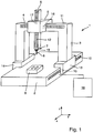
- Fig. 1 shows a coordinate measuring machine 1 with a basic bed 2.
- a portal 3 is arranged displaceably in the X direction.
- a carriage 5 is arranged displaceably in the Y direction.
- a displaceable in the Z direction quill 6 is arranged.
- a probe 7 is arranged on which in turn a tactile sensor, in the present example, a stylus 8 is arranged.
- a workpiece 9 is arranged for measurement with the coordinate measuring machine 1.
- the scale 10 is arranged on the base bed 2, the scale 11 is arranged on the cross member 4 of the portal 3 and the scale 12 is disposed on the sleeve 6.
- the gantry 3 has a driven portal foot 13 and a non-driven portal foot 14.
- the scale 10 detects the position of the driven gantry foot 13.
- the gauges are assigned giver devices 15, 16, 17, which are shown only schematically.
- the donor device 15 is arranged in the portal foot 13 and interacts with the scale 10.
- the encoder device 16 is arranged on the carriage 5 and cooperates with the scale 11.
- the encoder device 17 is also arranged in the carriage 5 and cooperates with the scale 12 of the sleeve 6.
- an evaluation and control device 18 is provided (shown only schematically).
- an acceleration sensor 19 is arranged in the probe 7.
- the position of the portal foot 13 by means of the encoder device 15 and the scale 10 is determined.
- the acceleration sensor 19 in the probe 7 detects an acceleration signal.
- the position signal of the portal foot 13 is differentiated twice, so that an acceleration is obtained.
- the difference is formed with the acceleration signal of the acceleration sensor 19 of the probe 7 and this variable is used to correct the measured values and / or the travel path and / or the travel speed.
- the position of the portal foot 13 in relation to the scale 10 is also detected by means of the encoder device 15 of the portal foot 13.
- the acceleration signal of the acceleration sensor 19 is detected in the probe 7.
- the acceleration signal is integrated twice so that a position is obtained as a physical quantity.
- a subtraction of the integrated acceleration signal of the acceleration sensor 19 of the probe 7 and the position signal of the portal foot 13 is performed. This value obtained is used to correct the measured values and / or the travel path and / or the travel speed.
- This method can also be carried out in place of or in addition to the described method with the position signal of the encoder device 15 with the position signals of the encoder devices 16 and / or 17.
- the acceleration signal of the acceleration sensor 19 is only offset with the position signal of the encoder device 15.
- the acceleration signal of the acceleration sensor 19 can also be offset only or additionally with the position signal of the encoder device 16.
- the position signal of the acceleration sensor 19 can additionally or exclusively be offset with the position signal of the encoder device 17.
- an optical sensor (not shown) can be substituted.
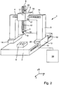
- Fig. 2 shows the coordinate measuring machine 1. The same parts are provided with the same reference numbers.
- a further acceleration sensor 20 is arranged in the portal foot, which is shown only schematically.
- the acceleration signal of the acceleration sensor 19 is detected in the probe 7.
- the acceleration signal of the acceleration sensor 20 in the portal foot 13 is detected.
- the integrated or non-integrated acceleration signal of the acceleration sensor 19 of the probe 7 is always used. This signal is individually offset with the acceleration signals of the acceleration sensors 20, 21 or 22. It is possible to determine the correction values for each axis.
- the portal foot which is the driven portal foot of the portal 3
- the portal foot 14 runs down, causing a deformation of the portal.
- This deformation affects the actual travel of the probe 7.
- this deformation can be compensated by means of a corresponding correction of the measured values and / or the travel path and / or the travel speed.
- the acceleration signal of the acceleration sensor 19 of the probe 7 with the acceleration signal of the acceleration sensor 20 of the portal foot 13 according to the method according to the invention.
- the signal of the acceleration sensors 16 or 17 can also be used in each case.
- Fig. 3 shows the carriage 5, which is arranged on the cross member 4 of the portal 3 of the coordinate measuring machine 1.
- the acceleration sensor 19 is disposed in the housing-fixed part.
- the sensor 21 which measures an acceleration signal of the carriage 5, is arranged in the carriage 5.
- the carriage is movable in the Y direction, as shown by the arrow.
- Fig. 4 shows the in Fig. 3 illustrated quill.
- the carriage 5 is moved in the direction of arrow A. Due to the inertia of the mass, the carriage 5 is in the axis B, while the quill 6 and the probe 7 run after. In Fig. 4 this trailing is much more illustrated for clarity than it is in reality.
- the acceleration signal of the acceleration sensor 21 is detected and the acceleration signal of the acceleration sensor 19. These two signals are subtracted from each other and it is integrated once or twice. It is also possible to integrate the signals once or twice and then to form the difference of the signals. From these values, in particular when integrated twice, the distance to which the sleeve is undesirably deflected relative to axis B is detected.
- the correction value can either be used to compensate for the dynamics of the deflection. For example, it is possible to let the carriage 5 continue to travel by the path of the deflection. It can with the correction value be driven to the dynamically corrected location.
- the other possibility is to subsequently correct the measured values with the detected and determined correction values.
- Fig. 5 shows a coordinate measuring machine 1 with an optical sensor 24.
- the same parts are provided with the same reference numerals.
- the procedure is analogous to Fig. 1 applied. It is only the tactile probe 7 has been substituted for the optical sensor 24.
Abstract
Verfahren und Koordinatenmessgerät zur Koordinatenmessung an Werkstücken mit einem Tastkopf, wobei Maßstabswerte ermittelt werden, wobei aufgrund der Maßstabswerte die Position des Tastkopfes bei der Berührung des Werkstückes ermittelt wird, wobei der Tastkopf einen Beschleunigungssensor aufweist, wobei das Beschleunigungssignal des Beschleunigungssensors des Tastkopfes und ein Positionssignal eines Maßstabes einer Achse und/oder wenigstens eines weiteren Beschleunigungssensors, der die Beschleunigung wenigstens einer mechanischen Vorrichtung des Koordinatenmessgerätes erfasst, durch Integrieren und/oder Differenzieren zu miteinander verrechenbaren physikalischen Größen umgewandelt werden, wobei aus diesen Größen die Differenz gebildet wird, wobei die Differenz zur Korrektur der Messwerte und/oder des Verfahrweges und/oder der Verfahrgeschwindigkeit verwendet werden. (Fig. 1).

Description
Die Erfindung betrifft ein Koordinatenmessgerät zur Koordinatenmessung von Werkstücken sowie ein Verfahren zur Koordinatenmessung an Werkstücken auf einem Koordinatenmessgerät.The invention relates to a coordinate measuring machine for coordinate measurement of workpieces and to a method for measuring coordinates on workpieces on a coordinate measuring machine.
Zum Stand der Technik (
Gemäß diesem Stand der Technik wird der Beschleunigungssensor verwendet, um das Tastkopfsignal zu überprüfen, dahingehend, ob eine Berührung vorliegt oder nicht.According to this prior art, the acceleration sensor is used to check the probe signal, whether there is a touch or not.
Gemäß diesem Stand der Technik soll ein Verfahren zur Koordinatenmessung angegeben werden, bei der fehlerhafte Antastungen verhindert werden, ohne die Bedingungen zu verändern, unter denen eine Antastung erkannt wird.According to this prior art, a method for coordinate measurement is to be specified in which erroneous probing be prevented without changing the conditions under which a probing is detected.
Dieses zum Stand der Technik gehörende Verfahren gibt kein Korrekturverfahren an, mit dem eine Verformung der Strukturen des Koordinatenmessgerätes bei hohen Geschwindigkeiten erfasst und korrigiert werden kann.This prior art method does not provide a correction method by which deformation of the coordinate measuring machine structures at high speeds can be detected and corrected.
Das der Erfindung zugrundeliegende technische Problem besteht darin, ein Koordinatenmessgerät zur Koordinatenmessung von Werkstücken sowie ein Verfahren zur Koordinatenmessung an Werkstücken anzugeben, mit denen eine Verformung der Strukturen des Koordinatenmessgerätes bei Messungen mit hohen Geschwindigkeiten korrigiert werden können.The technical problem underlying the invention is a coordinate measuring machine for coordinate measurement of workpieces and a method for coordinate measurement specify on workpieces with which a deformation of the structures of the coordinate measuring machine can be corrected for measurements at high speeds.
Dieses technische Problem wird durch ein Verfahren mit den Merkmalen gemäß Anspruch 1 sowie durch ein Koordinatenmessgerät mit den Merkmalen gemäß Anspruch 11 gelöst.This technical problem is solved by a method having the features according to
Das erfindungsgemäße Verfahren zur Koordinatenmessung an Werkstücken auf einem Koordinatenmessgerät mit einem Tastkopf und/oder einem optischen Sensorwobei der Tastkopf und/oder der optische Sensor einen Beschleunigungssensor aufweist, der bei Beschleunigungen des Tastkopfes und/oder des optischen Sensors ein Beschleunigungssignal erzeugt, wobei der Tastkopf und/oder der optische Sensor mit mechanischen Vorrichtungen relativ zum Werkstück bewegt wird, wobei mit Maßstäben, aus denen Maßstabswerte ermittelt werden, die Position des Tastkopfes und/oder des optischen Sensors als Positionswert für mindestens eine Achse ermittelt wird, zeichnet sich dadurch aus, dass das Beschleunigungssignal des Beschleunigungssensors des Tastkopfes und/oder des optischen Sensors und ein Positionssignal eines Maßstabes einer Achse und/oder wenigstens eines weiteren Beschleunigungssensors, der an einer der mechanischen Vorrichtungen angeordnet ist und die Beschleunigung der wenigstens einen mechanischen Vorrichtung erfasst, durch Integrieren und/oder Differenzieren zu miteinander verrechenbaren physikalischen Größen umgewandelt werden, und dass aus diesen Größen die Differenz gebildet wird, und dass die Differenz zur Korrektur der Messwerte und/oder des Verfahrweges und/oder der Verfahrgeschwindigkeit verwendet werden.The method according to the invention for coordinate measurement on workpieces on a coordinate measuring machine with a probe and / or an optical sensor, wherein the probe and / or the optical sensor has an acceleration sensor which generates an acceleration signal during acceleration of the probe and / or the optical sensor, wherein the probe and or the optical sensor with mechanical devices is moved relative to the workpiece, with scales from which scale values are determined, the position of the probe and / or the optical sensor is determined as a position value for at least one axis, characterized in that the Acceleration signal of the acceleration sensor of the probe and / or the optical sensor and a position signal of a scale of an axis and / or at least one further acceleration sensor, which is arranged on one of the mechanical devices and the acceleration of at least one mechani detected, converted by integrating and / or differentiating into mutually attributable physical quantities, and that the difference is formed from these variables, and that the difference for correcting the measured values and / or the travel path and / or the travel speed are used.
Mit dem erfindungsgemäßen Verfahren ist es möglich, Korrekturwerte zu ermitteln, die Messfehler kompensieren, die beim Messen mit hohen Geschwindigkeiten auftreten, dadurch dass sich die Struktur des Koordinatenmessgerätes verformt. Diese Verformung bildet sich als Formabweichung in den Messergebnissen ab.With the method according to the invention it is possible to determine correction values which compensate measurement errors, which occur when measuring at high speeds, characterized in that the structure of the coordinate measuring machine deforms. This deformation is reflected as a shape deviation in the measurement results.
Geht man beispielsweise von einem Koordinatenmessgerät in Portalbauweise aus, so weist das Portal zwei Füße auf, die das Portal in einer Achse, beispielsweise der X-Achse des Koordinatenmessgerätes bewegen. Ein Fuß ist ein angetriebener Fuß. Der zweite Fuß läuft in der Regel nach.For example, assuming a gantry-type coordinate measuring machine, the gantry has two feet that move the gantry in an axis, such as the X-axis of the coordinate measuring machine. A foot is a powered foot. The second foot usually runs.
Um beispielsweise das Nachlaufen des einen Fußes und die damit einhergehende Verformung des Portales zu erfassen, kann entweder ein Positionswert des Maßstabes, der beispielsweise am Werkstücktisch angeordnet ist und die Position des angetriebenen Fußes erfasst und verwendet werden, um einen Korrekturwert zu ermitteln. Es ist auch möglich, in dem angetriebenen Portalfuß einen weiteren Beschleunigungssensor anzuordnen, der ein Beschleunigungssignal liefert.For example, to detect the run-on of the one foot and the concomitant deformation of the portal, either a positional value of the scale, for example, arranged on the workpiece table and the position of the driven foot can be detected and used to determine a correction value. It is also possible to arrange a further acceleration sensor in the driven portal foot, which supplies an acceleration signal.
In dem Tastkopf und/oder dem optischen Sensor ist ein Beschleunigungssensor angeordnet, der bei Beschleunigungen des Tastkopfes und/oder des optischen Sensors ein Beschleunigungssignal erzeugt. Dieses Beschleunigungssignal wird mit entweder der Maßstabsposition, das heißt der Position beispielsweise des Portales oder einer anderen bewegten Struktur des Koordinatenmessgerätes verrechnet, oder es wird das Beschleunigungssignal des Beschleunigungssensors des Tastkopfes und/oder des optischen Sensors mit dem Beschleunigungssignal des weiteren Beschleunigungssensors, der an der mechanischen Vorrichtung angeordnet ist, verrechnet. Hierzu werden durch Integrieren und/oder Differenzieren die Beschleunigungssignale oder Positionssignale zu miteinander verrechenbaren physikalischen Größen umgewandelt. Das bedeutet, dass entweder sämtliche Signale in Beschleunigungssignale, Geschwindigkeiten oder Positionswerte durch Integrieren und/oder Differenzieren umgewandelt werden. Anschließend kann aus diesen Größen die Differenz gebildet werden. Diese Differenz wird zur Korrektur der Messwerte und/oder des Verfahrweges und/oder der Verfahrgeschwindigkeit verwendet.In the probe and / or the optical sensor, an acceleration sensor is arranged, which generates an acceleration signal during accelerations of the probe and / or the optical sensor. This acceleration signal is offset with either the scale position, that is, the position of, for example, the portal or other moving structure of the coordinate measuring machine, or it is the acceleration signal of the acceleration sensor of the probe and / or the optical sensor with the acceleration signal of the further acceleration sensor, the mechanical Device is arranged, charged. For this purpose, the acceleration signals or position signals are added by integrating and / or differentiating converted into billable physical quantities. This means that either all signals are converted into acceleration signals, velocities or position values by integrating and / or differentiating. Subsequently, the difference can be formed from these variables. This difference is used to correct the measured values and / or the travel and / or the travel speed.
Über die beiden Werte, das heißt das Beschleunigungssignal des Beschleunigungssensors des Tastkopfes und/oder des optischen Sensors und das Positionssignal oder das Beschleunigungssignal des weiteren Beschleunigungssensors, der an einer mechanischen Vorrichtung angeordnet ist, wird eine Relativbewegung zwischen den Komponenten erfasst. Hierdurch können Dynamikunterschiede erfasst werden. Diese Relativbewegung kann beispielsweise in dem beschriebenen Nachlaufen eines Portalfußes liegen.About the two values, that is, the acceleration signal of the acceleration sensor of the probe and / or the optical sensor and the position signal or the acceleration signal of the further acceleration sensor, which is arranged on a mechanical device, a relative movement between the components is detected. As a result, dynamic differences can be detected. This relative movement can be, for example, in the described tracking of a portal foot.
Gemäß einer vorteilhaften Ausführungsform der Erfindung ist vorgesehen, dass der Tastkopf einen Taster und einen dem Taster zugeordneten Tastsensor aufweist, der bei Berührung eines Werkstückes mit dem Taster ein Tastsignal erzeugt, bei dem Maßstabswerte ermittelt werden, wobei aufgrund der Maßstabswerte die Position des Tastkopfes bei der Berührung des Werkstückes ermittelt wird. Es handelt sich hierbei um ein taktiles Antastvefahren.According to an advantageous embodiment of the invention, it is provided that the probe has a button and a touch sensor associated with the probe, which generates a tact signal when touching a workpiece with the button, are determined in the scale values, the position of the probe due to the scale values in the Touching the workpiece is determined. This is a tactile Antastvefahren.
Eine andere vorteilhafte Ausführungsform der Erfindung sieht vor, dass der Tastkopf einen optischen Sensor aufweist, mit dem eine berührungslose Messung des Werkstückes erfolgt.Another advantageous embodiment of the invention provides that the probe has an optical sensor, with which a non-contact measurement of the workpiece takes place.
Der Taster und der optische Sensor können an dem Tastkopf eingewechselt werden.The button and the optical sensor can be switched on the probe.
Gemäß dem erfindungsgemäßen Verfahren besteht auch die Möglichkeit, dass der gesamte Tastkopf gegen einen optischen Sensor eingewechselt wird.According to the method of the invention, there is also the possibility that the entire probe head is exchanged for an optical sensor.
Es gibt also die folgenden Möglichkeiten:
- a) an dem Tastkopf ist ein taktiler und/oder ein optischer Sensor angeordnet, oder
- b) es ist an Stelle des Tastkopfes ein optischer Sensor vorgesehen.
- a) on the probe a tactile and / or an optical sensor is arranged, or
- b) an optical sensor is provided instead of the probe.
Das erfindungsgemäße Verfahren bezieht sich auf die Anordnung eines Beschleunigungssensors in dem Tastkopf oder in dem optischen Sensor.The method according to the invention relates to the arrangement of an acceleration sensor in the probe or in the optical sensor.
Gemäß einer vorteilhaften Ausführungsform der Erfindung ist vorgesehen, dass das Beschleunigungssignal des Beschleunigungssensors des Tastkopfes und/oder des optischen Sensors zweimal integriert wird und dass aus einem Positionswert einer Achse und dem integrierten Wert des Beschleunigungssignales eine Differenz gebildet wird.According to an advantageous embodiment of the invention, it is provided that the acceleration signal of the acceleration sensor of the probe and / or the optical sensor is integrated twice and that a difference is formed from a position value of an axis and the integrated value of the acceleration signal.
Es besteht auch die Möglichkeit, dass der Positionswert einer Achse zweimal differenziert wird und dass die Differenz aus dem differenzierten Positionswert und dem Beschleunigungssignal des Beschleunigungssensors des Tastkopfes und/oder des optischen Sensors gebildet wird.There is also the possibility that the position value of an axis is differentiated twice and that the difference is formed from the differentiated position value and the acceleration signal of the acceleration sensor of the probe and / or of the optical sensor.
Auch hierbei werden wieder die verschiedenen Größen jeweils zu miteinander verrechenbaren physikalischen Größen durch Differenzieren und/oder Integrieren umgewandelt, um die Differenz der Größen zu bilden. Diese Differenz kann wiederum zur Korrektur der Messwerte und/oder des Verfahrweges und/oder der Verfahrgeschwindigkeit verwendet werden.Again, the different sizes are each converted into mutually offset physical quantities by differentiating and / or integrating to form the difference of the sizes. This difference can in turn be used to correct the measured values and / or the travel and / or the travel speed.
Gemäß einer weiteren vorteilhaften Ausführungsform der Erfindung ist vorgesehen, dass mit dem wenigstens einen weiteren Beschleunigungssensor, der an wenigstens einer der mechanischen Vorrichtungen angeordnet ist, die Beschleunigung der wenigstens einen mechanischen Vorrichtung erfasst wird und dass die Differenz des Beschleunigungssignales des an dem am Tastkopf und/oder des an dem optischen Sensor angeordneten Beschleunigungssensors und dem Beschleunigungssignal des wenigstens einen zusätzlichen Beschleunigungssensors wenigstens einmal integriert wird, oder dass das Beschleunigungssignal des an dem Tastkopf und/oder an dem optischen Sensor angeordneten Beschleunigungssensors und des Beschleunigungssensors des wenigstens einen weiteren Beschleunigungssensors wenigstens einmal integriert wird und dass aus den integrierten Werten die Differenz gebildet wird.According to a further advantageous embodiment of the invention it is provided that with the at least one further acceleration sensor, which is arranged on at least one of the mechanical devices, the acceleration of the at least one mechanical device is detected and that the difference of the acceleration signal at the on the probe and / or. or the acceleration sensor of the at least one additional acceleration sensor arranged on the optical sensor and the acceleration signal of the acceleration sensor arranged on the probe and / or on the optical sensor and the acceleration sensor of the at least one further acceleration sensor are integrated at least once and that the difference is formed from the integrated values.
Bei dieser Ausführungsform sind zwei Beschleunigungssensoren vorgesehen, nämlich einmal der Beschleunigungssensor in dem Tastkopf und/oder in dem optischen Sensor und ein weiterer Beschleunigungssensor, der an wenigstens einer der mechanischen Vorrichtungen angeordnet ist.In this embodiment, two acceleration sensors are provided, namely once the acceleration sensor in the probe and / or in the optical sensor and another acceleration sensor, which is arranged on at least one of the mechanical devices.
Bei diesem Ausführungsbeispiel kann entweder die Differenz der beiden Beschleunigungssignale einmal integriert werden. Es besteht auch die Möglichkeit, beide Beschleunigungssignale erst zu integrieren und anschließend aus den integrierten Werten die Differenz zu bilden. Auch diese Werte können wiederum zur Korrektur der Messwerte und/oder des Verfahrweges und/oder der Verfahrgeschwindigkeit verwendet werden.In this embodiment, either the difference of the two acceleration signals can be integrated once. It is also possible to first integrate both acceleration signals and then to form the difference from the integrated values. These values can also be used to correct the measured values and / or the travel path and / or the travel speed.
Gemäß einer weiteren vorteilhaften Ausführungsform der Erfindung wird das Beschleunigungssignal des Beschleunigungssensors des Tastkopfes und/oder des optischen Sensors einmal integriert und ein Positionswert einer Achse wird einmal differenziert und aus diesen Werten wird eine Differenz gebildet. In diesem Fall ist als physikalische Größe eine Geschwindigkeit vorgesehen. Es kann die Differenz aus diesen Geschwindigkeiten gebildet werden. Es besteht anschließend die Möglichkeit, diese Geschwindigkeit zu integrieren. Hierdurch erhält man ein Positionssignal, welches wiederum zur Korrektur herangezogen werden kann.According to a further advantageous embodiment of the invention, the acceleration signal of the acceleration sensor of the probe and / or the optical sensor is integrated once and a position value of an axis is differentiated once and a difference is formed from these values. In this case, a speed is provided as a physical quantity. The difference between these speeds can be formed. It is then possible to integrate this speed. This gives a position signal, which in turn can be used for correction.
Gemäß einer weiteren vorteilhaften Ausführungsform der Erfindung ist vorgesehen, dass die physikalischen Größen "Position" zweimal differenziert werden, oder die physikalischen Größen "Beschleunigung" zweimal integriert werden. Das bedeutet, dass entweder die miteinander zu verrechnenden physikalischen Größen in Beschleunigungswerte umgewandelt werden und miteinander verrechnet werden, oder dass die Beschleunigungen in Geschwindigkeiten umgerechnet werden und dann ebenfalls miteinander verrechnet werden können. Die Verrechnung erfolgt vorteilhaft durch die Differenzbildung der Werte, das heißt durch Subtraktion. Andere Verrechnungsmethoden sind auch möglich. Es besteht auch die Möglichkeit, die Messwerte in einen Kalman-Filter einzugeben.According to a further advantageous embodiment of the invention it is provided that the physical quantities "position" are differentiated twice, or the physical quantities "acceleration" are integrated twice. This means that either the physical quantities to be offset together are converted into acceleration values and offset against each other, or that the accelerations are converted into speeds and can then also be offset against each other. The billing is advantageously carried out by the subtraction of the values, that is, by subtraction. Other billing methods are also possible. It is also possible to enter the measured values in a Kalman filter.
Eine weitere vorteilhafte Ausführungsform der Erfindung sieht vor, dass die Differenz achsenweise aus dem Beschleunigungssignal des Beschleunigungssensors des Tastkopfes und/oder des optischen Sensors mit jeweils einem Positionswert eines Maßstabes einer Achse nach Umwandlung in eine einheitliche physikalische Größe oder mit jeweils einem Beschleunigungssignal des Beschleunigungssensors gebildet wird.A further advantageous embodiment of the invention provides that the difference axis-wise from the acceleration signal of the acceleration sensor of the probe and / or the optical sensor, each having a position value of a scale of an axis after conversion into a uniform physical size or with one Acceleration signal of the acceleration sensor is formed.
Bei der achsenweisen Korrektur wird das Beschleunigungssignal des Beschleunigungssensors des Tastkopfes und/oder des optischen Sensors entweder mit jeweils einem Positionswert eines Maßstabes einer Achse oder mit jeweils einem Beschleunigungssignal des Beschleunigungssensors einer Achse gebildet.In the axis-wise correction, the acceleration signal of the acceleration sensor of the probe and / or the optical sensor is formed either with a respective position value of a scale of an axis or with an acceleration signal of the acceleration sensor of an axis.
Eine weitere vorteilhafte Ausführungsform der Erfindung sieht vor, dass die Korrektur der Messwerte nach Erfassen der Messwerte durchgeführt wird, oder dass eine Korrektur des Verfahrweges und/oder der Verfahrgeschwindigkeit während des Messvorganges durchgeführt wird. Bei der ersten Ausführungsform werden erst die Messwerte erfasst und die Messwerte im Nachhinein korrigiert.A further advantageous embodiment of the invention provides that the correction of the measured values is carried out after acquiring the measured values, or that a correction of the travel path and / or the travel speed is carried out during the measuring process. In the first embodiment, first the measured values are acquired and the measured values are subsequently corrected.
Bei der zweiten Ausführungsform wird die Korrektur des Verfahrweges und/oder der Verfahrgeschwindigkeit während des Messvorganges durchgeführt. Hierdurch wird die Dynamik kompensiert. Je nach Korrektur wird beispielsweise der Tastkopf und/oder der optische Sensor bei der Antastung etwas weiter oder etwas weniger weit gefahren, je nachdem, ob beschleunigt oder abgebremst wird. Hierbei wird vorausschauend in die Zukunft gerechnet, um vor dem Anfahren des Werkstückes schon zu ermitteln, ob weniger weit oder weiter gefahren werden muss. In diesem Fall kann mit dem Korrekturwert an die dynamisch korrigierte Stelle mit dem Tastkopf gefahren werden. Es handelt sich hierbei um eine Online-Korrektur.In the second embodiment, the correction of the travel path and / or the travel speed is performed during the measurement process. This compensates the dynamics. Depending on the correction, for example, the probe and / or the optical sensor is driven a little further or a little less when probing, depending on whether accelerated or decelerated. In this case, the future is anticipated in advance, in order to determine before starting the workpiece already, whether less far or has to continue. In this case it is possible to move with the correction value to the dynamically corrected point with the probe. This is an online correction.
Eine weitere vorteilhafte Ausführungsform der Erfindung sieht vor, dass die Korrektur der Messwerte bei einer Einzelpunktantastung oder bei einem Scanverfahren oder bei einer berührungslosen Messung durchgeführt wird.A further advantageous embodiment of the invention provides that the correction of the measured values in a Single point probing or in a scanning process or in a non-contact measurement is performed.
Die erfindungsgemäße Korrektur kann bei diesen Verfahren durchgeführt werden unabhängig davon, ob es sich um eine Einzelpunktantastung handelt oder um ein Scanverfahren oder um eine berührungslose Messung.The correction according to the invention can be carried out in these methods, regardless of whether it is a single point probing or a scanning method or a non-contact measurement.
Das erfindungsgemäße Koordinatenmessgerät zur Vermessung von Werkstücken mit einem Tastkopf mit einem Taster mit einem Tastsensor, der als ein bei Berührung des Tasters an einem Werkstück ein Tastsignal erzeugender Tastsensor ausgebildet ist, oder mit einem Tastkopf mit einem optischen Sensor, oder mit einem optischen Sensor, und mit einem Beschleunigungssensor, der als ein bei Beschleunigungen des Tastkopfes und/oder des optischen Sensors ein Beschleunigungssignal erzeugender Beschleunigungssensor ausgebildet ist, mit mechanischen Vorrichtungen, über die der Tastkopf und/oder der optische Sensor relativ zum Werkstück bewegbar ist, mit Maßstäben, aus denen Maßstabswerte ermittelbar sind, aus denen die Position des Tastkopfes und/oder des optischen Sensors ermittelbar ist, mit wenigstens einer Steuer- und Auswerteeinheit, zeichnet sich dadurch aus, dass wenigstens ein weiterer Beschleunigungssensor an wenigstens einer der mechanischen Vorrichtungen angeordnet ist und dass die wenigstens eine Auswerte- und Steuereinheit als eine aus dem Beschleunigungssignal des Beschleunigungssensors und dem Beschleunigungssignal des weiteren Beschleunigungssensors einer Achse die Differenz bildende und die Differenz ein- oder zweimal integrierende Auswerte- und Steuereinheit ausgebildet ist und dass die Auswerte- und Steuereinheit als eine die Differenz zur Korrektur der Messwerte und/oder des Verfahrweges und/oder der Verfahrgeschwindigkeit verwendende Auswerte- und Steuereinheit ausgebildet ist.The coordinate measuring machine according to the invention for measuring workpieces with a probe with a probe with a tactile sensor, which is designed as a touching the probe on a workpiece a Tastsignal generating push button, or with a probe with an optical sensor, or with an optical sensor, and with an acceleration sensor, which is designed as an acceleration sensor generating an acceleration signal during accelerations of the probe and / or the optical sensor, with mechanical devices, via which the probe and / or the optical sensor is movable relative to the workpiece, with scales from which scale values can be determined, from which the position of the probe and / or the optical sensor can be determined, with at least one control and evaluation unit, characterized in that at least one further acceleration sensor is arranged on at least one of the mechanical devices and that the at least one evaluation and control unit is formed as a from the acceleration signal of the acceleration sensor and the acceleration signal of the further acceleration sensor of an axis forming the difference and the difference once or twice integrating evaluation and control unit and that the evaluation and control unit as a difference to Correction of the measured values and / or the travel and / or the travel speed using evaluation and control unit is formed.
Durch diese erfindungsgemäße Ausführungsform wird zum einen die Beschleunigung in dem Tastkopf und/oder in dem optischen Sensor als Beschleunigungssignal erfasst. Zum anderen wird in wenigstens einer mechanischen Vorrichtung, über die der Tastkopf und/oder der optische Sensor relativ zum Werkstück bewegt wird, das Beschleunigungssignal dieser mechanischen Vorrichtung erfasst.By means of this embodiment according to the invention, on the one hand, the acceleration in the probe and / or in the optical sensor is detected as an acceleration signal. On the other hand, in at least one mechanical device via which the probe and / or the optical sensor is moved relative to the workpiece, the acceleration signal of this mechanical device is detected.
Aus dem Beschleunigungssignal des Tastkopfes und/oder des optischen Sensors und einem Beschleunigungssignal einer der mechanischen Vorrichtungen wird die Differenz gebildet. Diese Differenz wird einmal oder zweimal integriert.From the acceleration signal of the probe and / or the optical sensor and an acceleration signal of one of the mechanical devices, the difference is formed. This difference is integrated once or twice.
Das erfindungsgemäße Koordinatenmessgerät zur Vermessung von Werkstücken zur Durchführung des erfindungsgemäßen Verfahrens mit einem Tastkopf mit einem Taster, mit einem Tastsensor, der als ein bei Berührung des Tasters an einem Werkstück ein Tastsignal erzeugender Tastsensor ausgebildet ist, oder mit einem Tastkopf mit einem optischen Sensor, oder mit einem optischen Sensor, und mit einem Beschleunigungssensor, der als ein bei Beschleunigungen des Tastkopfes und/oder des optischen Sensors ein Beschleunigungssignal erzeugender Beschleunigungssensor ausgebildet ist, mit mechanischen Vorrichtungen, über die der Tastkopf und/oder der optische Sensor relativ zum Werkstück bewegbar ist, mit Maßstäben, aus denen Maßstabswerte ermittelbar sind, aus denen die Position des Tastkopfes und/oder des optischen Sensors ermittelbar ist, mit wenigstens einer Steuer- und Auswerteeinheit, zeichnet sich dadurch aus, dass die wenigstens eine Steuer- und Auswerteeinheit als eine das Beschleunigungssignal des Beschleunigungssensors des Tastkopfes und/oder des optischen Sensors und ein Positionssignal eines Maßstabes einer Achse durch Integrieren und/oder Differenzieren zu miteinander verrechenbaren physikalischen Größen umwandelnde und aus diesen Größen die Differenz bildende Auswerte- und Steuereinheit ausgebildet ist, und dass die Auswerte- und Steuereinheit als eine die Differenz zur Korrektur der Messwerte und/oder des Verfahrweges und/oder der Verfahrgeschwindigkeit verwendende Auswerte- und Steuereinheit ausgebildet ist.The coordinate measuring machine according to the invention for measuring workpieces for carrying out the method according to the invention with a probe with a probe, with a tactile sensor, which is designed as a touching when the probe on a workpiece a Tastsignal generating push button, or with a probe with an optical sensor, or with an optical sensor, and with an acceleration sensor, which is designed as an acceleration sensor generating an acceleration signal during accelerations of the probe and / or the optical sensor, with mechanical devices, via which the probe and / or the optical sensor is movable relative to the workpiece, with scales from which scale values can be determined, from which the position of the probe and / or the optical sensor can be determined, with at least one control and evaluation unit, characterized in that the at least one control and evaluation as a the acceleration igungssignal the acceleration sensor of the probe and / or the optical sensor and a position signal of a scale of an axis by integrating and / or differentiating to be accountable physical variables converting and from these sizes the difference forming evaluation and control unit is formed, and that the evaluation and control unit as a the difference is designed to correct the measured values and / or the travel path and / or the travel speed using evaluation and control unit.
Bei dieser Ausführungsform des Koordinatenmessgerätes ist lediglich der Beschleunigungssensor vorgesehen, der im Tastkopf und/oder in dem optischen Sensor angeordnet ist. Als zweiter Wert wird das Positionssignal eines Maßstabes einer Achse verwendet. Durch Integrieren und/oder Differenzieren werden miteinander verrechenbare physikalische Größen gebildet. Die Differenz dieser physikalischen Größen bilden einen Korrekturwert, der zur Korrektur der Messwerte und/oder des Verfahrweges und/oder der Verfahrgeschwindigkeit vorgesehen ist.In this embodiment of the coordinate measuring machine, only the acceleration sensor is provided, which is arranged in the probe and / or in the optical sensor. The second value used is the position signal of a scale of an axis. Integrating and / or differentiating together formable physical variables. The difference between these physical quantities forms a correction value which is provided for the correction of the measured values and / or the travel path and / or the travel speed.
Eine vorteilhafte Ausführungsform des erfindungsgemäßen Koordinatenmessgerätes sieht vor, dass die mechanischen Vorrichtungen relativ zum Maßstab beweglich ausgebildet sind und dass der wenigstens eine weitere Beschleunigungssensor am beweglichen Teil der mechanischen Vorrichtung angeordnet ist.An advantageous embodiment of the coordinate measuring machine according to the invention provides that the mechanical devices are designed to be movable relative to the scale and that the at least one further acceleration sensor is arranged on the movable part of the mechanical device.
Die mechanischen Vorrichtungen sind relativ zueinander und jeweils zu ihrem zugeordneten Maßstab beweglich angeordnet. Es kann sich hierbei um einen Werkzeugtisch und das Portal handeln. Es kann sich hierbei auch um das Portal und einen an dem Portal beweglich angeordneten Schlitten handeln. Darüber hinaus kann es sich auch um eine an dem Schlitten beweglich angeordnete Pinole handeln.The mechanical devices are arranged relative to each other and movable in each case to their assigned scale. This can be a tool table and the portal. This may also be the portal and a carriage movably arranged on the portal. In addition, it may also be a sleeve movably arranged on the sleeve.
Beispielsweise ist an dem Werkzeugtisch ein Maßstab vorgesehen und in dem Portal, insbesondere in dem Portalfuß eine Gebervorrichtung. In diesem Fall kann der weitere Beschleunigungssensor in dem Portalfuß angeordnet sein.For example, a scale is provided on the tool table and in the portal, in particular in the portal foot, a donor device. In this case, the further acceleration sensor can be arranged in the portal foot.
Ein weiterer Maßstab ist an einer Traverse des Portales angeordnet. Eine Gebervorrichtung ist dann in dem beweglich an dem Portal angeordneten Schlitten vorgesehen. In diesem Fall ist in dem Schlitten ein Beschleunigungssensor angeordnet. Die Pinole ist beweglich an dem Schlitten angeordnet. Hierzu weist die Pinole einen Maßstab auf und eine Gebervorrichtung ist in dem Schlitten angeordnet. Der Beschleunigungssensor ist hierbei in der Pinole angeordnet.Another scale is arranged on a traverse of the portal. A donor device is then provided in the carriage movably arranged on the portal. In this case, an acceleration sensor is arranged in the carriage. The quill is movably arranged on the carriage. For this purpose, the sleeve on a scale and a donor device is arranged in the carriage. The acceleration sensor is arranged in the quill here.
Gemäß einer vorteilhaften Ausführungsform der Erfindung ist an dem oder den Maßstäben jeweils eine Gebervorrichtung zur Ermittlung der Maßstabswerte angeordnet.According to an advantageous embodiment of the invention, a respective encoder device for determining the scale values is arranged on the one or more scales.
Eine weitere vorteilhafte Ausführungsform der Erfindung sieht vor, dass der wenigstens eine weitere Beschleunigungssensor an einem Portal und/oder an einem Schlitten und/oder an einer Pinole des Koordinatenmessgerätes angeordnet ist.A further advantageous embodiment of the invention provides that the at least one further acceleration sensor is arranged on a portal and / or on a carriage and / or on a quill of the coordinate measuring machine.
Eine weitere vorteilhafte Ausführungsform der Erfindung sieht vor, dass der im Tastkopf und/oder im optischen Sensor angeordnete Beschleunigungssensor am gehäusefesten Teil des Tastkopfes und/oder des optischen Sensors angeordnet ist.A further advantageous embodiment of the invention provides that the acceleration sensor arranged in the probe and / or in the optical sensor is arranged on the housing-fixed part of the probe and / or the optical sensor.
Hierdurch wird die Beschleunigung des Tastkopfes und/oder des optischen Sensors selbst erfasst.As a result, the acceleration of the probe and / or the optical sensor itself is detected.
Gemäß einer weiteren vorteilhaften Ausführungsform der Erfindung ist vorgesehen, dass die Beschleunigungssensoren als piezoelektrische Sensoren und/oder als Dehnungsmessstreifen und/oder als magnetische Sensoren ausgebildet sind. Die Beschleunigungssensoren können unterschiedlich ausgestaltet sein. Es kann sich hierbei um einen piezoelektrischen Sensor handeln, der einen piezoelektrischen Messgrößenaufnehmer und einen hieran befestigen Massekörper aufweist. Es kann aber auch ein Dehnungsmessstreifen verwendet werden, an dem ein Massekörper befestigt ist, oder ein magnetischer Sensor, bei dem ein an einer Feder aufgehängter Massekörper durch einen Magneten in einer Spule eine elektrische Spannung induziert. Bekannt sind beispielsweise auch miniaturisierte Beschleunigungssensoren, so genannte mikro-elektromechanische Systeme (MEMS), die aus Silizium hergestellt werden. Diese Sensoren sind Feder-Masse-Systeme, bei denen die Federn nur wenige mikrometerbreite Silizium-Stege sind und auch der Massekörper aus Silizium hergestellt ist, wobei durch die Auslenkung bei Beschleunigung zwischen dem gefedert aufgehängten Teil und einer festen Bezugselektrode eine Änderung der elektrischen Kapazität gemessen werden kann. Auch piezoresistive Widerstände werden in MEMS genutzt, um die Auslenkung zu messen.According to a further advantageous embodiment of the invention, it is provided that the acceleration sensors are designed as piezoelectric sensors and / or as strain gauges and / or as magnetic sensors. The acceleration sensors can be designed differently. It may be a piezoelectric sensor having a piezoelectric Meßgrößenaufnehmer and a mass body attached thereto. But it can also be used a strain gauge, to which a mass body is attached, or a magnetic sensor, in which a suspended on a spring mass body by a magnet in a coil induces an electrical voltage. Also known, for example, miniaturized acceleration sensors, so-called micro-electro-mechanical systems (MEMS), which are made of silicon. These sensors are spring-mass systems in which the springs are only a few microns wide silicon lands and also the mass body is made of silicon, wherein measured by the deflection during acceleration between the spring-suspended part and a fixed reference electrode, a change in the electrical capacitance can be. Piezoresistive resistors are also used in MEMS to measure the deflection.
Der Beschleunigungssensor kann prinzipiell beliebig ausgestaltet sein und an einer beliebigen Stelle im Bereich des Tastkopfes und/oder des optischen Sensors, jedoch am gehäusefesten Teil des Tastkopfes und/oder des optischen Sensors befestigt sein.In principle, the acceleration sensor can have any desired configuration and be fastened at any point in the region of the probe head and / or the optical sensor, but on the housing-fixed part of the probe head and / or the optical sensor.
Gemäß einer weiteren vorteilhaften Ausführungsform der Erfindung ist vorgesehen, dass das Koordinatenmessgerät als ein ein Scanverfahren oder eine Einzelpunktantastung durchführendes Koordinatenmessgerät ausgebildet ist. Das Koordinatenmessgerät kann auch als ein berührungslose Messungen durchführendes Koordinatenmessgerät ausgebildet sein.According to a further advantageous embodiment of the invention, it is provided that the coordinate measuring machine is designed as a coordinate measuring machine which carries out a scanning method or a single-point scanning. The coordinate measuring machine can also be designed as a non-contact measurements coordinate measuring machine.
Das Koordinatenmessgerät, auf dem das erfindungsgemäße Verfahren ausgeführt wird, kann unterschiedlich ausgestaltet sein. Es kann sich beispielsweise um ein Portalmessgerät, ein Brückenmessgerät, ein Horizontalarmmessgerät oder ein Messgerät mit Drehgelenken handeln, so dass es auf die Mechanik, mit der der Tastkopf und/oder der optische Sensor relativ zum Werkstück bewegt wird, nicht ankommt.The coordinate measuring machine, on which the method according to the invention is carried out, can be designed differently. It can be, for example, a portal measuring device, a bridge measuring device, a horizontal arm measuring device or a measuring device with hinges, so that it does not arrive at the mechanism with which the probe and / or the optical sensor is moved relative to the workpiece.
Aus dem Beschleunigungssignal des Tastkopfes und/oder des optischen Sensors und einem Beschleunigungssignal einer der mechanischen Vorrichtungen wird die Differenz gebildet. Diese Differenz wird einmal oder zweimal integriert.From the acceleration signal of the probe and / or the optical sensor and an acceleration signal of one of the mechanical devices, the difference is formed. This difference is integrated once or twice.
Weitere Merkmale und Vorteile der Erfindung ergeben sich anhand der zugehörigen Zeichnungen, in denen verschiedene Ausführungsformen eines erfindungsgemäßen Koordinatenmessgerätes nur beispielhaft dargestellt sind, ohne die Erfindung auf diese Ausführungsbeispiele zu beschränken. In den Zeichnungen zeigen:
- Fig. 1
- ein Koordinatenmessgerät in perspektivischer Ansicht mit einem im Tastkopf angeordneten Beschleunigungssensor;
- Fig. 2
- ein Koordinatenmessgerät in perspektivischer Ansicht mit einem im Tastkopf angeordneten Beschleunigungssensor und weiteren Beschleunigungssensoren in den mechanischen Vorrichtungen;
- Fig. 3
- eine schematische Darstellung eines Schlittens auf Traverse und einer Pinole und eines Tastkopfes in Ruhestellung;
- Fig. 4
- eine schematische Darstellung des Schlittens auf Traverse und der Pinole und des Tastkopfes gemäß
Fig. 3 in Bewegung; - Fig. 5
- ein Koordinatenmessgerät in perspektivischer Ansicht mit einem in einem optischen Sensor angeordneten Beschleunigungssensor.
- Fig. 1
- a coordinate measuring machine in a perspective view with an arranged in the probe acceleration sensor;
- Fig. 2
- a coordinate measuring machine in perspective view with a arranged in the probe Acceleration sensor and other acceleration sensors in the mechanical devices;
- Fig. 3
- a schematic representation of a carriage on traverse and a quill and a probe in the rest position;
- Fig. 4
- a schematic representation of the carriage on traverse and the quill and the probe according to
Fig. 3 moving; - Fig. 5
- a coordinate measuring machine in perspective view with an arranged in an optical sensor acceleration sensor.
Auf dem Grundbrett 2, welches den Werkstücktisch darstellt, ist ein Werkstück 9 zur Vermessung mit dem Koordinatenmessgerät 1 angeordnet.On the
Zur Erfassung der Positionen des Portales 3 des Schlittens 5 und der Pinole 6 sind Maßstäbe 10, 11, 12 vorgesehen. Der Maßstab 10 ist an dem Grundbett 2 angeordnet, der Maßstab 11 ist an der Traverse 4 des Portales 3 angeordnet und der Maßstab 12 ist an der Pinole 6 angeordnet. Das Portal 3 weist einen angetriebenen Portalfuß 13 auf und einen nicht angetriebenen Portalfuß 14. Der Maßstab 10 erfasst die Position des angetriebenen Portalfußes 13. Den Maßstäben zugeordnet sind Gebervorrichtungen 15, 16, 17, die lediglich schematisch dargestellt sind. Die Gebervorrichtung 15 ist in dem Portalfuß 13 angeordnet und wirkt mit dem Maßstab 10 zusammen. Die Gebervorrichtung 16 ist an dem Schlitten 5 angeordnet und wirkt mit dem Maßstab 11 zusammen. Die Gebervorrichtung 17 ist ebenfalls in dem Schlitten 5 angeordnet und wirkt mit dem Maßstab 12 der Pinole 6 zusammen.For detecting the positions of the
Zur Auswertung der Gebervorrichtungen 15, 16, 17 sowie zur Steuerung des Antriebes (nicht dargestellt) ist (lediglich schematisch dargestellt) eine Auswerte- und Steuereinrichtung 18 vorgesehen.For evaluation of the
Im Tastkopf 7 ist ein Beschleunigungssensor 19 angeordnet.In the
Gemäß einer ersten Ausführungsform der Erfindung wird die Position des Portalfußes 13 mittels der Gebervorrichtung 15 und dem Maßstab 10 bestimmt.According to a first embodiment of the invention, the position of the
Der Beschleunigungssensor 19 in dem Tastkopf 7 erfasst ein Beschleunigungssignal.The
Das Positionssignal des Portalfußes 13 wird zweimal differenziert, so dass eine Beschleunigung erhalten wird. Es wird die Differenz mit dem Beschleunigungssignal des Beschleunigungssensors 19 des Tastkopfes 7 gebildet und diese Größe wird zur Korrektur der Messwerte und/oder des Verfahrweges und/oder der Verfahrgeschwindigkeit verwendet.The position signal of the
Gemäß einer weiteren Ausführungsform der Erfindung wird ebenfalls mittels der Gebervorrichtung 15 des Portalfußes 13 die Position des Portalfußes 13 in Relation zum Maßstab 10 erfasst. Darüber hinaus wird das Beschleunigungssignal des Beschleunigungssensors 19 in den Tastkopf 7 erfasst. Das Beschleunigungssignal wird zweimal integriert, so dass als physikalische Größe eine Position erhalten wird. Es wird eine Subtraktion des aufintegrierten Beschleunigungssignales des Beschleunigungssensors 19 des Tastkopfes 7 und des Positionssignales des Portalfußes 13 durchgeführt. Dieser erhaltene Wert wird zur Korrektur der Messwerte und/oder des Verfahrweges und/oder der Verfahrgeschwindigkeit verwendet.According to a further embodiment of the invention, the position of the
Dieses Verfahren kann auch anstelle oder zusätzlich zu dem beschriebenen Verfahren mit dem Positionssignal der Gebervorrichtung 15 mit den Positionssignalen der Gebervorrichtungen 16 und/oder 17 durchgeführt werden.This method can also be carried out in place of or in addition to the described method with the position signal of the
Es besteht die Möglichkeit, dass das Beschleunigungssignal des Beschleunigungssensors 19 nur mit dem Positionssignal der Gebervorrichtung 15 verrechnet wird. Das Beschleunigungssignal des Beschleunigungssensors 19 kann auch nur oder auch zusätzlich mit dem Positionssignal der Gebervorrichtung 16 verrechnet werden. Das Positionssignal des Beschleunigungssensors 19 kann zusätzlich oder auch ausschließlich mit dem Positionssignal der Gebervorrichtung 17 verrechnet werden.There is the possibility that the acceleration signal of the
An dem Tastkopf 7 kann an Stelle des Taststiftes 8 auch ein optischer Sensor (nicht dargestellt) eingewechselt werden.On the
Zusätzlich zu der Gebervorrichtung 15 ist in dem Portalfuß ein weiterer Beschleunigungssensor 20 angeordnet, der lediglich schematisch dargestellt ist.In addition to the
Gemäß einer weiteren Ausführungsform der Erfindung wird das Beschleunigungssignal des Beschleunigungssensors 19 im Tastkopf 7 erfasst. Darüber hinaus wird das Beschleunigungssignal des Beschleunigungssensors 20 im Portalfuß 13 erfasst.According to a further embodiment of the invention, the acceleration signal of the
Es bestehen nun folgende Möglichkeiten:
- 1) Die Differenz aus beiden Beschleunigungssignalen wird gebildet und der Differenzwert wird einmal oder zweimal integriert. Der erhaltene Wert wird zur Korrektur der Messwerte und/oder des Verfahrweges und/oder der Verfahrgeschwindigkeit verwendet.
- 2) Das
Beschleunigungssignal des Beschleunigungssensors 19 desTastkopfes 7 und das Beschleunigungssignal des Beschleunigungssensors 20 des Portalfußes 13 werden erfasst. Beide Signale werden einmal oder zweimal integriert. Anschließend wird die Differenz der jeweils einmal oder zweimal aufintegrierten Signale gebildet. Dieser Wert wird zur Korrektur der Messwerte und/oder des Verfahrweges und/oder der Verfahrgeschwindigkeit verwendet.
- 1) The difference between both acceleration signals is formed and the difference value is integrated once or twice. The value obtained is used to correct the measured values and / or the travel and / or the travel speed.
- 2) The acceleration signal of the
acceleration sensor 19 of theprobe 7 and the acceleration signal of theacceleration sensor 20 of theportal foot 13 are detected. Both signals are integrated once or twice. Subsequently, the difference of the signals integrated once or twice is formed. This value is used to correct the measured values and / or the travel distance and / or the travel speed.
Es besteht die Möglichkeit, zusätzliche Beschleunigungssensoren in dem Schlitten und der Pinole anzuordnen. Lediglich schematisch sind hierzu in dem Schlitten der Beschleunigungssensor 21 und in der Pinole der Beschleunigungssensor 22 dargestellt.It is possible to arrange additional acceleration sensors in the carriage and quill. Only schematically are this purpose in the carriage of the
Zur Differenzbildung wird immer das integrierte oder nicht integrierte Beschleunigungssignal des Beschleunigungssensors 19 des Tastkopfes 7 verwendet. Dieses Signal wird einzeln mit den Beschleunigungssignalen der Beschleunigungssensoren 20, 21 oder 22 verrechnet. Es kann für jede Achse eine Ermittlung der Korrekturwerte erfolgen.To calculate the difference, the integrated or non-integrated acceleration signal of the
Mit dem erfindungsgemäßen Verfahren ist es möglich, eine Verformung von Strukturen des Koordinatenmessgerätes 1 zu erfassen.With the method according to the invention, it is possible to detect a deformation of structures of the coordinate measuring
Wird beispielsweise der Portalfuß, der der angetriebene Portalfuß des Portales 3 ist, bewegt, so läuft der Portalfuß 14 nach, wodurch eine Verformung des Portales entsteht. Diese Verformung wirkt sich auf den tatsächlichen Verfahrweg des Tastkopfes 7 aus. Mit dem erfindungsgemäßen Verfahren und dem erfindungsgemäßen Koordinatenmessgerät 1 kann diese Verformung über eine entsprechende Korrektur der Messwerte und/oder des Verfahrweges und/oder der Verfahrgeschwindigkeit kompensiert werden.If, for example, the portal foot, which is the driven portal foot of the
Es besteht gemäß der Erfindung auch die Möglichkeit, das Beschleunigungssignal des Beschleunigungssensors 19 des Tastkopfes 7 mit dem Beschleunigungssignal des Beschleunigungssensors 20 des Portalfußes 13 gemäß dem erfindungsgemäßen Verfahren zu verrechnen. Für die Y- oder Z-Achse kann auch jeweils das Signal der Beschleunigungssensoren 16 oder 17 verwendet werden. Es besteht jedoch auch die Möglichkeit, keine weiteren Beschleunigungssensoren 16 oder 17 vorzusehen, sondern in der Y- und Z-Richtung die Positionssignale zur Ermittlung des Korrekturwertes heranzuziehen, wie zur der
Um das Nachlaufen zu erfassen und anschließend korrigieren zu können, wird das Beschleunigungssignal des Beschleunigungssensors 21 erfasst sowie das Beschleunigungssignal des Beschleunigungssensors 19. Diese beiden Signale werden voneinander subtrahiert und es wird ein- oder zweimal integriert. Es besteht auch die Möglichkeit, die Signale erst ein- oder zweimal zu integrieren und dann die Differenz der Signale zu bilden. Aus diesen Werten, insbesondere wenn zweimal integriert wird, wird die Wegstrecke erfasst, um die die Pinole sich unerwünschterweise auslenkt gegenüber der Achse B.In order to detect the Nachlauf and then correct, the acceleration signal of the
Der Korrekturwert kann entweder verwendet werden, um die Dynamik der Auslenkung zu kompensieren. Es besteht zum Beispiel die Möglichkeit, den Schlitten 5 um den Weg der Auslenkung weiter fahren zu lassen. Es kann mit dem Korrekturwert an die dynamisch korrigierte Stelle gefahren werden.The correction value can either be used to compensate for the dynamics of the deflection. For example, it is possible to let the
Die andere Möglichkeit besteht darin, im Nachhinein die Messwerte mit den erfassten und ermittelten Korrekturwerten zu korrigieren.The other possibility is to subsequently correct the measured values with the detected and determined correction values.
- 11
- Koordinatenmessgerätcoordinate measuring machine
- 22
- Grundbettbasic bed
- 33
- Portalportal
- 44
- Traversetraverse
- 55
- Schlittencarriage
- 66
- PinolePinole
- 77
- Tastkopfprobe
- 88th
- Taststiftfeeler
- 99
- Werkstückworkpiece
- 1010
- Maßstab Grundbett/PortalScale basic bed / portal
- 1111
- Maßstab Portal/SchlittenScale portal / sled
- 1212
- Maßstab Schlitten/PinoleScale slide / quill
- 1313
- Portalfuß angetriebenPortal foot driven
- 1414
- Portalfuß nicht angetriebenPortal foot not driven
- 1515
- Gebervorrichtung PortalDonor device portal
- 1616
- Gebervorrichtung SchlittenEncoder device slide
- 1717
- Gebervorrichtung PinoleEncoder device quill
- 1818
- Auswerte- und SteuereinrichtungEvaluation and control device
- 1919
- Beschleunigungssensor TastkopfAccelerometer probe
- 2020
- Beschleunigungssensor PortalAccelerometer portal
- 2121
- Beschleunigungssensor SchlittenAcceleration sensor slide
- 2222
- Beschleunigungssensor PinoleAcceleration sensor quill
- 2323
- Tastkugelprobe ball
- 2424
- optischer Sensoroptical sensor
- AA
- Pfeilarrow
Claims (18)
dadurch gekennzeichnet, dass das Beschleunigungssignal des Beschleunigungssensors (19) des Tastkopfes (7) und/oder des optischen Sensors (24) und ein Positionssignal eines Maßstabes (10, 11, 12) einer Achse und/oder wenigstens eines weiteren Beschleunigungssensors (20, 21, 22), der an einer der mechanischen Vorrichtungen angeordnet ist und die Beschleunigung der wenigstens einen mechanischen Vorrichtung (3, 5, 6) erfasst, durch Integrieren und/oder Differenzieren zu miteinander verrechenbaren physikalischen Größen umgewandelt werden, und dass aus diesen Größen die Differenz gebildet wird, und dass die Differenz zur Korrektur der Messwerte und/oder des Verfahrweges und/oder der Verfahrgeschwindigkeit verwendet werden.Method for coordinate measurement on workpieces on a coordinate measuring machine (1) with a probe head (7) and / or an optical sensor (24), wherein the probe head (7) and / or the optical sensor has an acceleration sensor (19) which during acceleration of the Probe (7) and / or the optical sensor (24) generates an acceleration signal, wherein the probe (7) and / or the optical sensor with mechanical devices relative to the workpiece (9) is moved, wherein by scales (10, 11, 12 ) from which scale values are determined, the position of the probe head (7) and / or the optical sensor (24) is determined as the position value for at least one axis (X, Y, Z),
characterized in that the acceleration signal of the acceleration sensor (19) of the probe (7) and / or the optical sensor (24) and a position signal of a scale (10, 11, 12) of an axis and / or at least one further acceleration sensor (20, 21 , 22), which is arranged on one of the mechanical devices and detects the acceleration of the at least one mechanical device (3, 5, 6), are converted by integrating and / or differentiating into physical variables that can be offset against each other, and that the difference is formed, and that the difference for the correction of the measured values and / or the travel path and / or the travel speed are used.
dadurch gekennzeichnet, dass die Korrektur der Messwerte nach Erfassen der Messwerte durchgeführt wird oder dass eine Korrektur des Verfahrweges und/oder der Verfahrgeschwindigkeit während des Messvorganges durchgeführt wird.Method according to one of the preceding claims,
characterized in that the correction of the measured values is carried out after acquiring the measured values or that a correction of the travel path and / or the travel speed is carried out during the measuring process.
Applications Claiming Priority (1)
| Application Number | Priority Date | Filing Date | Title |
|---|---|---|---|
| DE102017114713.6A DE102017114713A1 (en) | 2017-06-30 | 2017-06-30 | Coordinate measuring device for coordinate measurement of workpieces and method for coordinate measurement on workpieces on a coordinate measuring machine |
Publications (1)
| Publication Number | Publication Date |
|---|---|
| EP3421931A1 true EP3421931A1 (en) | 2019-01-02 |
Family
ID=62116356
Family Applications (1)
| Application Number | Title | Priority Date | Filing Date |
|---|---|---|---|
| EP18170799.3A Withdrawn EP3421931A1 (en) | 2017-06-30 | 2018-05-04 | Coordinate measuring machine for coordinate measurement of workpieces and method for measuring the coordinates of workpieces on a coordinate measuring machine |
Country Status (2)
| Country | Link |
|---|---|
| EP (1) | EP3421931A1 (en) |
| DE (1) | DE102017114713A1 (en) |
Cited By (1)
| Publication number | Priority date | Publication date | Assignee | Title |
|---|---|---|---|---|
| EP3901562A1 (en) * | 2020-04-23 | 2021-10-27 | Hexagon Metrology S.p.A. | Method for the compensation of measurement error of a coordinate measuring machine and a measuring machine using said method |
Families Citing this family (2)
| Publication number | Priority date | Publication date | Assignee | Title |
|---|---|---|---|---|
| DE102019127499B4 (en) * | 2019-10-11 | 2021-11-04 | Carl Zeiss Industrielle Messtechnik Gmbh | Coordinate measuring machine and control method of a coordinate measuring machine |
| DE102020110995A1 (en) | 2020-04-22 | 2021-10-28 | Carl Zeiss Industrielle Messtechnik Gmbh | Coordinate measuring machine |
Citations (8)
| Publication number | Priority date | Publication date | Assignee | Title |
|---|---|---|---|---|
| EP0684448A2 (en) * | 1994-05-27 | 1995-11-29 | Carl Zeiss | Procedure for coordinate measuring on workpieces |
| DE19637554A1 (en) * | 1995-09-19 | 1997-03-20 | Deutsche Forsch Luft Raumfahrt | Correcting measurement faults at measuring robot |
| DE19900587A1 (en) * | 1999-01-09 | 2000-07-13 | Reiner Foerst | Sensors on beams of moving system such as human body measure positions and angles relative to reference |
| WO2007122362A1 (en) * | 2006-04-21 | 2007-11-01 | Renishaw Plc | Method of error correction |
| DE102006036320A1 (en) * | 2006-08-03 | 2008-02-07 | Pepperl + Fuchs Gmbh | Moving target object e.g. motor vehicle, position determining device, has acceleration sensor connected with evaluating unit for providing positioning signal in consideration of measuring data of acceleration sensor |
| US20090287444A1 (en) * | 2008-05-13 | 2009-11-19 | Mitutoyo Corporation | Coordinate measuring machine |
| DE102010018250A1 (en) | 2010-04-23 | 2011-10-27 | Carl Zeiss Industrielle Messtechnik Gmbh | Method for measuring coordinates on workpieces on a coordinate measuring machine |
| WO2015082935A1 (en) * | 2013-12-06 | 2015-06-11 | Renishaw Plc | Calibrating the position of motion systems by using inertial sensors |
-
2017
- 2017-06-30 DE DE102017114713.6A patent/DE102017114713A1/en active Pending
-
2018
- 2018-05-04 EP EP18170799.3A patent/EP3421931A1/en not_active Withdrawn
Patent Citations (8)
| Publication number | Priority date | Publication date | Assignee | Title |
|---|---|---|---|---|
| EP0684448A2 (en) * | 1994-05-27 | 1995-11-29 | Carl Zeiss | Procedure for coordinate measuring on workpieces |
| DE19637554A1 (en) * | 1995-09-19 | 1997-03-20 | Deutsche Forsch Luft Raumfahrt | Correcting measurement faults at measuring robot |
| DE19900587A1 (en) * | 1999-01-09 | 2000-07-13 | Reiner Foerst | Sensors on beams of moving system such as human body measure positions and angles relative to reference |
| WO2007122362A1 (en) * | 2006-04-21 | 2007-11-01 | Renishaw Plc | Method of error correction |
| DE102006036320A1 (en) * | 2006-08-03 | 2008-02-07 | Pepperl + Fuchs Gmbh | Moving target object e.g. motor vehicle, position determining device, has acceleration sensor connected with evaluating unit for providing positioning signal in consideration of measuring data of acceleration sensor |
| US20090287444A1 (en) * | 2008-05-13 | 2009-11-19 | Mitutoyo Corporation | Coordinate measuring machine |
| DE102010018250A1 (en) | 2010-04-23 | 2011-10-27 | Carl Zeiss Industrielle Messtechnik Gmbh | Method for measuring coordinates on workpieces on a coordinate measuring machine |
| WO2015082935A1 (en) * | 2013-12-06 | 2015-06-11 | Renishaw Plc | Calibrating the position of motion systems by using inertial sensors |
Cited By (1)
| Publication number | Priority date | Publication date | Assignee | Title |
|---|---|---|---|---|
| EP3901562A1 (en) * | 2020-04-23 | 2021-10-27 | Hexagon Metrology S.p.A. | Method for the compensation of measurement error of a coordinate measuring machine and a measuring machine using said method |
Also Published As
| Publication number | Publication date |
|---|---|
| DE102017114713A1 (en) | 2019-01-03 |
Similar Documents
| Publication | Publication Date | Title |
|---|---|---|
| DE60311527T3 (en) | WORKPIECE INSPECTION PROCESS AND DEVICE | |
| DE3011003C2 (en) | Method and device for determining measured values on a workpiece | |
| DE102010052503B4 (en) | Method for controlling a coordinate measuring machine and coordinate measuring machine | |
| EP2486369B1 (en) | Coordinate measuring device having positional change sensors | |
| EP0301390B1 (en) | Feeler head for coordinate measuring machines | |
| DE602005005839T2 (en) | USE OF SURFACE TESTS | |
| DE102015209193A1 (en) | Method for detecting dynamic vibrations of a roughness sensor, method for measuring the roughness of a workpiece surface, computer program product and measuring device configured to carry out the method. | |
| DE4436507A1 (en) | Coordinate measurement of workpiece using coordinate measuring unit | |
| DE10124493A1 (en) | High precision correction of continuously-measured workpiece co-ordinates, takes accelerations and dynamic flexural behavior of sensor into account | |
| EP2561312B1 (en) | Method for measuring the coordinates of workpieces on a coordinate-measuring device | |
| WO2009130169A1 (en) | Measuring method for an articulated-arm coordinate measuring machine | |
| EP3421931A1 (en) | Coordinate measuring machine for coordinate measurement of workpieces and method for measuring the coordinates of workpieces on a coordinate measuring machine | |
| EP0684448B1 (en) | Coordinate measurement on workpieces with corrections of accelerations | |
| DE102019208946A1 (en) | Method and device for determining a position of an axis of rotation of a turntable as well as turntable and coordinate measuring machine | |
| DE10258579B4 (en) | measuring device | |
| EP1839011B1 (en) | Method for determining a space coordinate of a measuring point on a test object and corresponding coordinate measuring device | |
| DE102010015780A1 (en) | Operation of a coordinate measuring machine or a machine tool | |
| EP3480557A1 (en) | Method for measuring a workpiece using a coordinate measuring machine | |
| DE102017003641B4 (en) | Method for measuring coordinates or properties of a workpiece surface | |
| DE10157174A1 (en) | Method and device for the spatial measurement of workpieces on a machine tool | |
| EP3351895B1 (en) | Measuring device and method for operating a measuring device | |
| DE3826783C1 (en) | Multicoordinate measuring instrument | |
| EP2663832A1 (en) | Method and arrangement for calibrating sensors of a tactile coordinate measuring device that provide measured values | |
| DE10313895B3 (en) | Device for determining machine tool and/or production machine component position has contactless measurement arrangement joined to crossbeam to detect deflection relative to auxiliary crossbeam | |
| DE102014201438B4 (en) | Device and method for mounting a detection device for detecting properties of a measurement object |
Legal Events
| Date | Code | Title | Description |
|---|---|---|---|
| PUAI | Public reference made under article 153(3) epc to a published international application that has entered the european phase |
Free format text: ORIGINAL CODE: 0009012 |
|
| AK | Designated contracting states |
Kind code of ref document: A1 Designated state(s): AL AT BE BG CH CY CZ DE DK EE ES FI FR GB GR HR HU IE IS IT LI LT LU LV MC MK MT NL NO PL PT RO RS SE SI SK SM TR |
|
| AX | Request for extension of the european patent |
Extension state: BA ME |
|
| RIN1 | Information on inventor provided before grant (corrected) |
Inventor name: KIRCHHOF, MICHAEL |
|
| STAA | Information on the status of an ep patent application or granted ep patent |
Free format text: STATUS: REQUEST FOR EXAMINATION WAS MADE |
|
| 17P | Request for examination filed |
Effective date: 20190628 |
|
| RBV | Designated contracting states (corrected) |
Designated state(s): AL AT BE BG CH CY CZ DE DK EE ES FI FR GB GR HR HU IE IS IT LI LT LU LV MC MK MT NL NO PL PT RO RS SE SI SK SM TR |
|
| STAA | Information on the status of an ep patent application or granted ep patent |
Free format text: STATUS: THE APPLICATION IS DEEMED TO BE WITHDRAWN |
|
| 18D | Application deemed to be withdrawn |
Effective date: 20201201 |