EP3901548A2 - Generativ gefertigte trägerstruktur für sperrschicht - Google Patents
Generativ gefertigte trägerstruktur für sperrschicht Download PDFInfo
- Publication number
- EP3901548A2 EP3901548A2 EP21164462.0A EP21164462A EP3901548A2 EP 3901548 A2 EP3901548 A2 EP 3901548A2 EP 21164462 A EP21164462 A EP 21164462A EP 3901548 A2 EP3901548 A2 EP 3901548A2
- Authority
- EP
- European Patent Office
- Prior art keywords
- container
- interior
- exterior
- wall
- fluid
- Prior art date
- Legal status (The legal status is an assumption and is not a legal conclusion. Google has not performed a legal analysis and makes no representation as to the accuracy of the status listed.)
- Withdrawn
Links
Images


Classifications
-
- B—PERFORMING OPERATIONS; TRANSPORTING
- B33—ADDITIVE MANUFACTURING TECHNOLOGY
- B33Y—ADDITIVE MANUFACTURING, i.e. MANUFACTURING OF THREE-DIMENSIONAL [3D] OBJECTS BY ADDITIVE DEPOSITION, ADDITIVE AGGLOMERATION OR ADDITIVE LAYERING, e.g. BY 3D PRINTING, STEREOLITHOGRAPHY OR SELECTIVE LASER SINTERING
- B33Y10/00—Processes of additive manufacturing
-
- F—MECHANICAL ENGINEERING; LIGHTING; HEATING; WEAPONS; BLASTING
- F28—HEAT EXCHANGE IN GENERAL
- F28D—HEAT-EXCHANGE APPARATUS, NOT PROVIDED FOR IN ANOTHER SUBCLASS, IN WHICH THE HEAT-EXCHANGE MEDIA DO NOT COME INTO DIRECT CONTACT
- F28D9/00—Heat-exchange apparatus having stationary plate-like or laminated conduit assemblies for both heat-exchange media, the media being in contact with different sides of a conduit wall
- F28D9/0062—Heat-exchange apparatus having stationary plate-like or laminated conduit assemblies for both heat-exchange media, the media being in contact with different sides of a conduit wall the conduits for one heat-exchange medium being formed by spaced plates with inserted elements
-
- F—MECHANICAL ENGINEERING; LIGHTING; HEATING; WEAPONS; BLASTING
- F16—ENGINEERING ELEMENTS AND UNITS; GENERAL MEASURES FOR PRODUCING AND MAINTAINING EFFECTIVE FUNCTIONING OF MACHINES OR INSTALLATIONS; THERMAL INSULATION IN GENERAL
- F16J—PISTONS; CYLINDERS; SEALINGS
- F16J12/00—Pressure vessels in general
-
- F—MECHANICAL ENGINEERING; LIGHTING; HEATING; WEAPONS; BLASTING
- F28—HEAT EXCHANGE IN GENERAL
- F28D—HEAT-EXCHANGE APPARATUS, NOT PROVIDED FOR IN ANOTHER SUBCLASS, IN WHICH THE HEAT-EXCHANGE MEDIA DO NOT COME INTO DIRECT CONTACT
- F28D1/00—Heat-exchange apparatus having stationary conduit assemblies for one heat-exchange medium only, the media being in contact with different sides of the conduit wall, in which the other heat-exchange medium is a large body of fluid, e.g. domestic or motor car radiators
- F28D1/02—Heat-exchange apparatus having stationary conduit assemblies for one heat-exchange medium only, the media being in contact with different sides of the conduit wall, in which the other heat-exchange medium is a large body of fluid, e.g. domestic or motor car radiators with heat-exchange conduits immersed in the body of fluid
- F28D1/03—Heat-exchange apparatus having stationary conduit assemblies for one heat-exchange medium only, the media being in contact with different sides of the conduit wall, in which the other heat-exchange medium is a large body of fluid, e.g. domestic or motor car radiators with heat-exchange conduits immersed in the body of fluid with plate-like or laminated conduits
-
- F—MECHANICAL ENGINEERING; LIGHTING; HEATING; WEAPONS; BLASTING
- F28—HEAT EXCHANGE IN GENERAL
- F28D—HEAT-EXCHANGE APPARATUS, NOT PROVIDED FOR IN ANOTHER SUBCLASS, IN WHICH THE HEAT-EXCHANGE MEDIA DO NOT COME INTO DIRECT CONTACT
- F28D9/00—Heat-exchange apparatus having stationary plate-like or laminated conduit assemblies for both heat-exchange media, the media being in contact with different sides of a conduit wall
- F28D9/0081—Heat-exchange apparatus having stationary plate-like or laminated conduit assemblies for both heat-exchange media, the media being in contact with different sides of a conduit wall the conduits for one heat-exchange medium being formed by a single plate-like element ; the conduits for one heat-exchange medium being integrated in one single plate-like element
-
- F—MECHANICAL ENGINEERING; LIGHTING; HEATING; WEAPONS; BLASTING
- F28—HEAT EXCHANGE IN GENERAL
- F28F—DETAILS OF HEAT-EXCHANGE AND HEAT-TRANSFER APPARATUS, OF GENERAL APPLICATION
- F28F1/00—Tubular elements; Assemblies of tubular elements
- F28F1/003—Multiple wall conduits, e.g. for leak detection
-
- F—MECHANICAL ENGINEERING; LIGHTING; HEATING; WEAPONS; BLASTING
- F28—HEAT EXCHANGE IN GENERAL
- F28F—DETAILS OF HEAT-EXCHANGE AND HEAT-TRANSFER APPARATUS, OF GENERAL APPLICATION
- F28F13/00—Arrangements for modifying heat-transfer, e.g. increasing, decreasing
- F28F13/003—Arrangements for modifying heat-transfer, e.g. increasing, decreasing by using permeable mass, perforated or porous materials
-
- F—MECHANICAL ENGINEERING; LIGHTING; HEATING; WEAPONS; BLASTING
- F28—HEAT EXCHANGE IN GENERAL
- F28F—DETAILS OF HEAT-EXCHANGE AND HEAT-TRANSFER APPARATUS, OF GENERAL APPLICATION
- F28F3/00—Plate-like or laminated elements; Assemblies of plate-like or laminated elements
- F28F3/005—Arrangements for preventing direct contact between different heat-exchange media
-
- F—MECHANICAL ENGINEERING; LIGHTING; HEATING; WEAPONS; BLASTING
- F28—HEAT EXCHANGE IN GENERAL
- F28F—DETAILS OF HEAT-EXCHANGE AND HEAT-TRANSFER APPARATUS, OF GENERAL APPLICATION
- F28F3/00—Plate-like or laminated elements; Assemblies of plate-like or laminated elements
- F28F3/02—Elements or assemblies thereof with means for increasing heat-transfer area, e.g. with fins, with recesses, with corrugations
- F28F3/04—Elements or assemblies thereof with means for increasing heat-transfer area, e.g. with fins, with recesses, with corrugations the means being integral with the element
-
- F—MECHANICAL ENGINEERING; LIGHTING; HEATING; WEAPONS; BLASTING
- F28—HEAT EXCHANGE IN GENERAL
- F28F—DETAILS OF HEAT-EXCHANGE AND HEAT-TRANSFER APPARATUS, OF GENERAL APPLICATION
- F28F3/00—Plate-like or laminated elements; Assemblies of plate-like or laminated elements
- F28F3/12—Elements constructed in the shape of a hollow panel, e.g. with channels
-
- F—MECHANICAL ENGINEERING; LIGHTING; HEATING; WEAPONS; BLASTING
- F28—HEAT EXCHANGE IN GENERAL
- F28F—DETAILS OF HEAT-EXCHANGE AND HEAT-TRANSFER APPARATUS, OF GENERAL APPLICATION
- F28F9/00—Casings; Header boxes; Auxiliary supports for elements; Auxiliary members within casings
- F28F9/001—Casings in the form of plate-like arrangements; Frames enclosing a heat exchange core
-
- B—PERFORMING OPERATIONS; TRANSPORTING
- B33—ADDITIVE MANUFACTURING TECHNOLOGY
- B33Y—ADDITIVE MANUFACTURING, i.e. MANUFACTURING OF THREE-DIMENSIONAL [3D] OBJECTS BY ADDITIVE DEPOSITION, ADDITIVE AGGLOMERATION OR ADDITIVE LAYERING, e.g. BY 3D PRINTING, STEREOLITHOGRAPHY OR SELECTIVE LASER SINTERING
- B33Y80/00—Products made by additive manufacturing
-
- F—MECHANICAL ENGINEERING; LIGHTING; HEATING; WEAPONS; BLASTING
- F28—HEAT EXCHANGE IN GENERAL
- F28F—DETAILS OF HEAT-EXCHANGE AND HEAT-TRANSFER APPARATUS, OF GENERAL APPLICATION
- F28F13/00—Arrangements for modifying heat-transfer, e.g. increasing, decreasing
- F28F2013/005—Thermal joints
-
- F—MECHANICAL ENGINEERING; LIGHTING; HEATING; WEAPONS; BLASTING
- F28—HEAT EXCHANGE IN GENERAL
- F28F—DETAILS OF HEAT-EXCHANGE AND HEAT-TRANSFER APPARATUS, OF GENERAL APPLICATION
- F28F2265/00—Safety or protection arrangements; Arrangements for preventing malfunction
- F28F2265/22—Safety or protection arrangements; Arrangements for preventing malfunction for draining
Definitions
- the present disclosure relates to heat exchangers.
- the present disclosure relates to a support structure positioned in a barrier layer of a heat exchanger.
- a vessel includes an exterior container, an interior container, and a support structure.
- the exterior container is formed by an exterior wall that prevents transmission of a fluid.
- the interior container is by an interior layer disposed within the exterior container such that the exterior container encapsulates the interior container.
- the interior layer and the exterior wall are separated by a gap defining a barrier void.
- the interior layer prevents transmission of a fluid across the interior layer.
- the support structure is disposed within the barrier void between the exterior wall and the interior layer.
- the support structure comprises a lattice and is integrally formed with the exterior wall and the interior layer. The support structure is connected to and extends between the exterior wall and the interior layer.
- a heat exchanger includes an exterior container, an interior container, a stack of layers, and a third portion.
- the exterior container is formed by an exterior wall that is non-permeable to a fluid.
- the interior container is formed by an interior wall that is non-permeable to a fluid.
- the interior container is disposed within the exterior container such that the exterior container encapsulates the interior container.
- the interior wall and the exterior wall are separated by a gap that defines a barrier void.
- Each layer of the stack of layers includes a portion of the interior container and a portion of the external container.
- the third portion is disposed within the barrier void and between the exterior wall and the interior wall.
- the third portion is integrally formed with the exterior wall and the interior wall via additive manufacturing.
- the third portion includes a lattice and is connected to and extends between the exterior wall and the interior wall.
- a method of making a vessel includes forming a first portion with layer-by-layer additive manufacturing.
- the first portion defines an exterior container with at least one exterior wall that is non-permeable to a fluid.
- the second portion is formed with layer-by-layer additive manufacturing and defines at least one interior wall that is non-permeable to the fluid.
- the second portion defines an interior container encapsulated by the first container.
- the at least one third portion is formed with layer-by-layer additive manufacturing and has a lattice structure disposed between the at least one exterior wall and the at least one interior wall.
- the third portion is integrally formed with the first portion and the second portion.
- FIG. 1 is a perspective partial cross-section view of pressure vessel 10 and shows exterior container 12, (with exterior wall 14), inlet 16, outlet 18, interior container 20 (with interior wall 22), gap 24, and third portion 26.
- Pressure vessel 10 is a container configured to hold a pressurized fluid or fluids.
- pressure vessel 10 is configured as a double-wall pressure vessel.
- Pressure vessel 10 can be a reactive fluid heat exchanger.
- Exterior container 12 and interior container 20 are enclosed capsules.
- Exterior wall 14 and interior wall 22 are curved sheets of solid material.
- exterior wall 14 and interior wall 22 include cylindrical shapes with rounded ends.
- Inlet 16 and outlet 18 are fluidic ports.
- Gap 24 is a space or void.
- gap 24 is a barrier void or barrier layer of pressure vessel 10.
- the terms "barrier void" and “barrier layer” are used synonymously.
- gap 24 is shown as a double-wall barrier passage.
- Third portion 26 is a support structure. In this example, third portion 26 includes a lattice of solid material.
- pressure vessel 10 can be disposed in an aircraft and/or fluidly connected to a fluid management system of the aircraft, such as an air cycle machine or an environmental control system.
- Exterior container 12 contains or encapsulates interior container 20, gap 24, and third portion 26.
- Exterior wall 14 is disposed outward of interior wall 22 and is integrally formed together with third portion 26 via layer-by-layer additive manufacturing.
- Inlet 16 and outlet 18 are disposed in different portions of exterior wall 14. Inlet 16 and outlet 18 extend into pressure vessel 10 and connect to interior wall 22 such that inlet 16 and outlet 18 fluidly connect an interior cavity of interior container 20 to an ambient environment external to pressure vessel 10.
- Interior container 20 is disposed and mounted within exterior container 12.
- Interior wall 22 is disposed inside of exterior wall 14 and is integrally connected to third portion 26 via layer-by-layer additive manufacturing.
- Gap 24 is disposed and extends between exterior wall 14 and interior wall 22.
- Third portion 26 is disposed in gap 24 and is integrally connected to exterior wall 14 and interior wall 22 via layer-by-layer additive manufacturing.
- pressure vessel 10 is a heat exchanger configured to transfer thermal energy to/from a first fluid inside of interior container 20 from/to a second fluid outside of exterior container 12.
- Pressure vessel 10 and its components are produced via layer-by-layer additive manufacturing such that every component of pressure vessel 10 is integrally formed together as a single piece of material.
- Exterior container 12 and interior container 20 contain and/or encapsulate a fluid or fluids.
- Exterior wall 14 provides an outer barrier of external container 12 and is configured to prevent transmission of a fluid across exterior wall 14.
- Inlet 16 receives a fluid from outside of pressure vessel 10 and transports the fluid into interior container 20.
- Outlet 18 transports the fluid from inside of interior container 20 to outside of pressure vessel 10.
- inlet 16 and/or outlet 18 can be fluidly connected to a component or components of the environmental control system or another engine component of the aircraft.
- Interior wall 22 is a structural wall that serves as an inner fluid barrier of interior container 20.
- Gap 24 acts as a barrier layer and potential flow path in the case of a leak of a fluid from either exterior wall 14 or interior wall 22 into gap 24.
- Gap 24 also is a barrier layer and safety mechanism to prevent mixing of reactive fluids.
- gap 24 provides a flow path for any fluid that leaks into gap 24 either through internal layer 22 or exterior wall 14.
- Third portion 26 provides structural support and thermal energy conduction between exterior wall 14 and interior wall 22. In this example, third portion 26 can be used to maximize thermal conduction.
- third portion 26 is accomplished by layer-by-layer additive manufacturing. Additionally, third portion 26 is designed to allow for layer-by-layer additive manufacture construction without the requirement of third portions during the build process as well as allowing for powder removal after manufacture of pressure vessel 10.
- the density and geometry of third portion 26 in gap 24 are selected based on associated structural loading of pressure vessel 10 to allow for rupture of interior wall 22 (e.g., that can be in contact with the higher pressure fluid), for leakage of the fluid into gap 24 without failure, and for leakage also to be passed through exterior wall 14. Gap 24 can then be routed to collection points (not shown) to allow for any leakages to be detected and thereby indicating necessary replacement or repair of pressure vessel 10.
- pressure vessel 10 with third portion 26 provides a lightweight means for routing a leak to a safe location while still providing heat transfer capability through a lattice (i.e., third portion 26) between the walls (i.e., exterior wall 14 and interior wall 22) of pressure vessel 10.
- Third portion 26 acts as a thermal load carrying element to improve heat transfer between exterior wall 14 and interior wall 22.
- Third portion 26 is arranged to maximize thermal load carrying while also limiting structural and thermal stresses across pressure vessel 10.
- Third portion 26 remains dense enough to act as a structural load carrying member and is permeable enough to allow a fluid to pass through whether from leakage into gap 24. In this way, pressure vessel 10 with integrally formed third portion 26 provides integral pressure vessel walls containing a barrier passage (e.g., gap 24) therebetween.
- pressure vessel 10 with third portion 26 Another benefit of pressure vessel 10 with third portion 26 is a reduced weight of pressure vessel 10 due to the thickness of the walls (e.g., exterior wall 14 and interior wall 22) being reduced due to the structural load carrying capability of third portion 26.
- Geometries of pressure vessel 10 and of third portion 26 can be contoured and conformal to meet packaging needs and can be optimized based on structural loading requirements of pressure vessel 10.
- Gap 24 with third portion 26 can be carried or transitioned through associated piping (e.g., inlet 16 and outlet 18) and headers without the added weight and/or complexity of multiple components. Likewise, dimensions of gap 24 can be varied depending on the required flow rate(s) and pressure of the fluid in specific areas of pressure vessel 10.
- Third portion 26 also provides improved thermal energy transfer between fluid internal and external to pressure vessel 10. For example, a conduction path between exterior container 12 and interior container 20 is improved compared to traditional designs without third portion 26.
- FIGS. 2A-2H are cross-section views of various designs of third portion 26, which are respectively depicted across FIGS. 2A-2H as third portions 26A-26H.
- Third portions 26A-26H are lattices with various shapes and configurations.
- FIG. 2A shows third portion 26A (with rods 28A and opening 30A) and pipe 32A.
- the lattice configuration of third portion 26A includes rods 28A and openings 30A.
- Rods 28A are elongate pieces of solid material.
- a diameter of each of rods 28A can be from 0.001 inches to 0.05 inches.
- rods 28A can include a variable diameter that expands towards the ends of each of rods 28A.
- a diameter of rods 28A can include a constant diameter.
- Openings 30A are spaces or voids. As shown in FIGS.
- pipes 32A-32H are included in the image to provide an example structure disposed adjacent to and in connection with third portions 26A-26H.
- pipes 32A-32H can be either one of exterior wall 14 or interior wall 22 shown in FIG. 1 .
- Rods 28A are connected to and integrally formed with inner surfaces of pipe 32A via layer-by-layer additive manufacturing.
- rods 28A are interconnected such that adjacent and adjoining rods connect to each other at orthogonal or right angles.
- the connection points of rods 28A can be called nodes.
- Openings 30A extend between rods 28A.
- openings 30A include a generally cuboid shape due to the orthogonal arrangement of rods 28A.
- openings 30A are all interconnected to form an open volume that is a continuous open cell network of voids and spaces.
- Rods 28A of third portion 26A are structural load carrying members. Openings 30A make third portion 26A permeable enough to allow a fluid to pass through structural member 26A, whether from fluid leakage into gap 24 (see e.g., FIG. 1 ) or for draining the fluid to a collection or supply point disposed in pressure vessel 10.
- the lattice configuration of structure 26A is formed by layer-by-layer additive manufacturing. The design described herein permits construction of third portion 26A without the need for supports during the build process and allows for powder removal after manufacture of pressure vessel 10.
- a density and a geometric design of third portion 26A is also developed based on the associated structural loading to allow for a rupture in interior wall 22 (that can be in contact with a higher pressure fluid) and/or leakage of a fluid of into gap 24 without failure of pressure vessel 10.
- Third portion 26B shown in FIG. 2B includes an orthogonal configuration of rods 28B similar to third portion 26A shown in FIG. 2A .
- a diameter of rods 28B of third portions 26B is larger and increases more near ends of each of rods 28B. Due to this, a shape of openings 30B include more of an ellipsoid or spherical shape as compared to openings 30A. Due to the increased thickness of rods 28B and size of connection points or nodes of third portion 26B, third portion 26B can provide increased structural support as well as increased thermal conductivity.
- Third portion 26C shown in FIG. 2C includes a sheet-like configuration with multiple sheets 28C stacked next to each other.
- Sheets 28C include openings 30C, which include a generally circular or octagonal shape.
- a greater amount of structural support can be provided along a particular axis of third portion 26C, such as in a direction of planes of sheets 28C (e.g., in a horizontal direction as shown in FIG. 2C ).
- Third portion 28D shown in FIG. 2D includes an angular array of rods 30D.
- This angular array of rods 28D causes openings 30D to include more of a pyramidal shape as compared to openings 30A-30C.
- Such an angular array of rods 28D in third portion 26D can provide structural support along a plurality of directions in comparison to along one or two directional planes.
- Third portion 26E in FIG. 2E is similar to third portion 26D, however third portion 26E includes rods 28E that are longer than rods 28D as well as openings 30E that are larger than openings 30D.
- third portion 26F in FIG. 2F includes rods 28F that are shorter than both rods 28D and 28E, as well as openings 30F that are smaller than openings 30D and 30E. These variations in sizes provide for varying degrees of structural support and thermal energy transfer between fluids flowing through interior container 20 and flowing across exterior container 12.
- the shape of third portions 26D, 26E, and 26F include a truss configuration.
- Third portions 26G and 26H in FIGS. 2G and 2H include a screen or mesh configuration of rods 28G and 28H, respectively.
- structural support 26H is less dense than structural support 26G, allowing for a higher rate of flow of a fluid across and through rods 28H of third portion 26H than through rods 28G of third portion 26G.
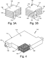
- FIG. 3A is a perspective view of interior container 120 and shows interior wall 122, layers 134, first header 136, second header 138, and port 140.
- FIG. 3B is a perspective view of exterior container 112 and shows exterior wall 114, layers 142, connections 144, and drain port 146.
- FIGS. 3A and 3B are herein discussed in tandem.
- interior container 120 is an interior container of a heat exchanger.
- Interior wall 122 is an external surface of interior container 120.
- Layers 134 are levels or discrete planar portions of interior container 120.
- First header 136 and second header 138 are conduits configured to direct a flow of a fluid.
- Port 140 is a tube or orifice in first header 136.
- Exterior container 112 is an external container of the heat exchanger.
- Exterior wall 114 is an external surface of external container 112.
- Layers 142 are levels or discrete planar portions of exterior container 112.
- Connections 144 and drain port 146 are channels.
- interior container 120 is shown in isolation.
- interior container 120 is shown as disposed inside of exterior container 112.
- Interior wall 122 wraps and extends around interior container 120 to form an external fluidic barrier of interior container 120.
- Layers 134 of interior container 120 are disposed in a stack pattern and are in fluid communication with each other via first and second headers 136 and 138.
- First header 136 and second header 138 are disposed on opposite corners of interior container 120. Both of first header 136 and second header 138 are connected to and in fluid communication with each of layers 134.
- Port 140 is mounted onto and fluidly connected to first header 136. In another example, there can be a second corresponding port similarly situated on second header 138.
- Exterior container 112 surrounds and contains interior container 120.
- Exterior wall 114 surrounds and contains interior wall 122 of interior container 120. Layers 142 of exterior container 114 are disposed in a stack pattern similar to layers 134 of interior container 120. Connections 144 extend between and fluidly connected adjacent layers 142 of external container 114. Drain port 146 is disposed on a bottom corner of exterior container 112. Drain port 146 is fluidly connected to an internal cavity of exterior container 112 formed by exterior wall 114.
- a first fluid is passed through interior container 120 and a second fluid is drawn across the outside of exterior wall of 114 of exterior container 112.
- the first fluid enters into first header 136 via port 140, into layers 134 of interior container 120, and out of interior container 120 through second header 138.
- thermal energy is transferred across interior wall 122 and exterior wall 114 between the first and second fluids.
- connections 144 provide a fluidic pathway by which the leaked fluid can travel through and towards drain port 146. Once the leaked fluid reaches drain port 146, the fluid can be withdrawn, detected, and/or sensed to indicate the presence of a leak.
- FIG. 4 is a perspective view of a single layer 142 of the stack of layers 142 and shows exterior container 112, exterior wall 114, interior container 120, interior wall 122, gap 124, and third portion 126.
- FIG. 4 shows a portion of exterior wall 114 cut-away to show gap 124 and third portion 126.
- layer 142 is one of layers 142 shown in FIG. 3B .
- Gap 124 is a space or void disposed and extending between interior wall 122 of interior container 120 and exterior wall 114 of exterior container 112.
- gap 124 is a barrier passage of a heat exchanger.
- Third portion 126 is a lattice of solid material disposed in gap 124.
- third portion 126 is shown as including orthogonal intersection points such as those displayed in FIG. 2A .
- the lattice type and/or configuration of third portion 126 in FIG. 4 can include any of the lattice configurations shown in FIGS. 2A-2H .
- exterior wall 114 forms an enclosed container that encases interior container 120 and third portion 126.
- Gaps 124 form a flow path envelope surrounding interior container 120.
- Gap 124 is in fluid communication with drain port 146 via connections 144 (see e.g., drain port 146 and connections 144 in FIG. 3B ).
- Third portion 126 is connected to and integrally formed with exterior wall 114 and interior wall 122 via layer-by-layer additive manufacturing.
- interfacing fluid channels typically contain fluids at varying pressures as well as varying temperatures and transients related to the structural and thermal loads.
- the interfacing fluid channels typically contain fluids at varying pressures as well as varying temperatures and transients related to the structural and thermal loads.
- differential thermal expansion occurs creating significant mechanical stress in the structure(s) between them.
- Other loads such as varying pressures or rapid thermal transients will similarly develop.
- gap 124 e.g., a barrier layer
- third portion 126 that both acts as a structural element of the heat exchanger as well as a thermal energy conductor.
- various parameters that control the lattice e.g., rod diameter, lattice solid vs.
- open volume number of interconnected rods/struts, spacing of central lattice nodes, rod size at lattice node, conformality of lattice to interfacing structures, pressure drop of lattice structure with passing fluid flow, etc.
- third portion 126 in the heat exchanger can be varied depending a location of third portion 126 in the heat exchanger as well as being based on a direct relationship between interfacing fluid channels, distance from headers (e.g., first and second headers 136 and 138), distance from mounting connections, distance from fluid inlets and exits (e.g., port 140), and distance from heat exchanger walls.
- the aforementioned lattice variables can be adjusted to provide stiffness, and support other structural elements, in reacting to the pressure load along the first direction but incorporate reduced stiffness in the second direction of the thermal loads allowing the heat exchanger to further deform thereby reducing stress.
- the lattice configuration of third portion 126 can be tuned to meet performance criteria or operational parameters of the heat exchanger.
- tuning of the lattice configuration of third portion 126 can be defined as locally controlling all the variables that make up the lattice to allow optimization of the overall heat exchanger. If the heat exchanger was defined into a rectangular or polar array of different nodes, the lattice variables can be tuned at each of those nodes to allow optimization of the overall heat exchanger design needs. A further tuning of the lattice can provide optimization of the lattice thermal energy transfer between fluids and the overall lattice weight (for weight sensitive applications).
- a methodology for defining the lattice geometry of third portion 126 can be to include an iterative cycle and the use of a multi-physics analysis model.
- a baseline model can be analyzed by utilizing computational flow dynamics and/or finite element analysis to calculate the associated global stresses created from the associated loads (e.g., temperature deltas between the first and second fluids, an external skin surface temperature of the heat exchanger, temperature transients, pressure deltas between interfacing fluids, mounting loads, etc.).
- the lattice configuration of third portion 126 can be generated manually based on operator knowledge and further upon analysis iterations completed and/or through specific topology optimization or lattice optimization tools. Due to the number of variables and complex loading of which the lattice is being tuned for, certain requirements can be prioritized the methodology to be developed. For example, tuning the lattice so as to increase or reduce thermal performance in order to improve the life of the heat exchanger.
- a vessel includes an exterior container, an interior container, and a support structure.
- the exterior container is formed by an exterior wall that prevents transmission of a fluid.
- the interior container is by an interior layer disposed within the exterior container such that the exterior container encapsulates the interior container.
- the interior layer and the exterior wall are separated by a gap defining a barrier void.
- the interior layer prevents transmission of a fluid across the interior layer.
- the support structure is disposed within the barrier void between the exterior wall and the interior layer.
- the support structure comprises a lattice and is integrally formed with the exterior wall and the interior layer. The support structure is connected to and extends between the exterior wall and the interior layer.
- the vessel of the preceding paragraph can optionally include, additionally and/or alternatively, any one or more of the following features, configurations and/or additional components.
- the vessel can be a heat exchanger comprising a stack of layers, wherein each layer can comprise a portion of the interior container and/or a portion of the external container.
- the third portion can be configured to transfer thermal energy between the first portion and the second portion.
- the third portion can be configured to transfer vibrational loads between the first portion and the second portion.
- the interior wall and the exterior wall can be separated by a gap that defines a barrier void, wherein the barrier void can form a flow path envelope surrounding the interior container.
- the interior wall and the exterior wall can be separated by a gap that defines a barrier void, wherein the barrier void can be in fluid communication with a drain port of the vessel.
- the lattice structure of the third portion can comprise a truss pattern.
- a heat exchanger includes an exterior container, an interior container, a stack of layers, and a third portion.
- the exterior container is formed by an exterior wall that is non-permeable to a fluid.
- the interior container is formed by an interior wall that is non-permeable to a fluid.
- the interior container is disposed within the exterior container such that the exterior container encapsulates the interior container.
- the interior wall and the exterior wall are separated by a gap that defines a barrier void.
- Each layer of the stack of layers includes a portion of the interior container and a portion of the external container.
- the third portion is disposed within the barrier void and between the exterior wall and the interior wall.
- the third portion is integrally formed with the exterior wall and the interior wall via additive manufacturing.
- the third portion includes a lattice and is connected to and extends between the exterior wall and the interior wall.
- the heat exchanger of the preceding paragraph can optionally include, additionally and/or alternatively, any one or more of the following features, configurations and/or additional components.
- a plurality of connections can extend between the layers of the stack of layers, wherein each connection of the plurality of connections fluidly can connect adjacent layers of the stack of layers.
- a drain port can be disposed in the exterior container, wherein the drain port can be in fluid communication with the plurality of connections and/or with the barrier void.
- the lattice pattern of the third portion can comprise a truss pattern.
- a method of making a vessel includes forming a first portion with layer-by-layer additive manufacturing.
- the first portion defines an exterior container with at least one exterior wall that is non-permeable to a fluid.
- the second portion is formed with layer-by-layer additive manufacturing and defines at least one interior wall that is non-permeable to the fluid.
- the second portion defines an interior container encapsulated by the first container.
- the at least one third portion is formed with layer-by-layer additive manufacturing and has a lattice structure disposed between the at least one exterior wall and the at least one interior wall.
- the third portion is integrally formed with the first portion and the second portion.
- the method of the preceding paragraph can optionally include, additionally and/or alternatively, any one or more of the following steps, features, configurations and/or additional components.
- a stack of layers can be formed, wherein each layer can comprise a portion of the interior container and a portion of the external container, wherein the vessel can be a heat exchanger.
- the third portion can be configured to transfer thermal energy between the first portion and the second portion.
- the third portion can be configured to transfer vibrational loads between the first portion and the second portion.
- the interior wall and/or the exterior wall can be formed such that the interior wall and the exterior wall can be separated by a gap that defines a barrier void, wherein the barrier void can form a flow path envelope surrounding the interior container.
- the interior wall and/or the exterior wall can be formed such that the interior wall and the exterior wall can be separated by a gap that defines a barrier void, wherein the barrier void can be in fluid communication with a drain port of the vessel.
- the lattice structure of the third portion can be formed to include a truss pattern.
Landscapes
- Engineering & Computer Science (AREA)
- General Engineering & Computer Science (AREA)
- Mechanical Engineering (AREA)
- Physics & Mathematics (AREA)
- Thermal Sciences (AREA)
- Chemical & Material Sciences (AREA)
- Manufacturing & Machinery (AREA)
- Materials Engineering (AREA)
- Dispersion Chemistry (AREA)
- Heat-Exchange Devices With Radiators And Conduit Assemblies (AREA)
- Packages (AREA)
- Filling Or Discharging Of Gas Storage Vessels (AREA)
Applications Claiming Priority (1)
| Application Number | Priority Date | Filing Date | Title |
|---|---|---|---|
| US202063001776P | 2020-03-30 | 2020-03-30 |
Publications (2)
| Publication Number | Publication Date |
|---|---|
| EP3901548A2 true EP3901548A2 (de) | 2021-10-27 |
| EP3901548A3 EP3901548A3 (de) | 2021-12-01 |
Family
ID=75203111
Family Applications (1)
| Application Number | Title | Priority Date | Filing Date |
|---|---|---|---|
| EP21164462.0A Withdrawn EP3901548A3 (de) | 2020-03-30 | 2021-03-24 | Generativ gefertigte trägerstruktur für sperrschicht |
Country Status (2)
| Country | Link |
|---|---|
| US (1) | US20210302103A1 (de) |
| EP (1) | EP3901548A3 (de) |
Families Citing this family (4)
| Publication number | Priority date | Publication date | Assignee | Title |
|---|---|---|---|---|
| US11988469B2 (en) * | 2020-03-30 | 2024-05-21 | Hamilton Sundstrand Corporation | Additively manufactured permeable barrier layer and method of manufacture |
| EP4541496A1 (de) * | 2023-10-17 | 2025-04-23 | Linde GmbH | Verfahren zur herstellung einer düseneinheit für einen druckbehälter |
| NL2036886B1 (nl) * | 2024-01-24 | 2025-08-06 | Jaxxco Capital B V | Buffervat, systeem voor het opslaan van thermische vloeistof, werkwijze voor het vervaardigen van een dergelijk buffervat, en een set onderdelen |
| US12415670B2 (en) * | 2024-02-23 | 2025-09-16 | Blue Origin Manufacturing, LLC | Systems and methods for fluid barriers through permeable structures |
Family Cites Families (12)
| Publication number | Priority date | Publication date | Assignee | Title |
|---|---|---|---|---|
| FR1544973A (fr) * | 1966-11-18 | 1968-11-08 | Marston Excelsior Ltd | échangeur de chaleur du type à plaques |
| GB1185469A (en) * | 1966-11-18 | 1970-03-25 | Marston Excelsior Ltd | Plate-Type Heat Exchanger. |
| US4210199A (en) * | 1978-06-14 | 1980-07-01 | Doucette Industries, Inc. | Heat exchange system |
| JPH0612216B2 (ja) * | 1985-02-27 | 1994-02-16 | バブコツク日立株式会社 | 熱交換器 |
| US6668561B1 (en) * | 2002-06-27 | 2003-12-30 | Northrop Grumman Corporation | Pressure regulated structure |
| GB0427362D0 (en) * | 2004-12-14 | 2005-01-19 | Sustainable Engine Systems Ltd | Heat exchanger |
| CN100398416C (zh) * | 2006-06-13 | 2008-07-02 | 黄晓东 | 安全环保型埋地储油罐 |
| EP2256067B1 (de) * | 2008-02-03 | 2013-01-09 | Shanghai Huapeng Explosion- Proof Science And Technology Co., Ltd. | Explosionssicherer Lagertank |
| US10371462B2 (en) * | 2015-09-21 | 2019-08-06 | Lockheed Martin Corporation | Integrated multi-chamber heat exchanger |
| US10527362B2 (en) * | 2015-09-21 | 2020-01-07 | Lockheed Martin Corporation | Integrated multi-chamber heat exchanger |
| US10589878B2 (en) * | 2016-12-12 | 2020-03-17 | The Boeing Company | Additively manufactured reinforced structure |
| US11300365B2 (en) * | 2018-06-19 | 2022-04-12 | General Electric Company | Heat exchanger and leak detection system |
-
2021
- 2021-03-24 EP EP21164462.0A patent/EP3901548A3/de not_active Withdrawn
- 2021-03-26 US US17/214,318 patent/US20210302103A1/en not_active Abandoned
Also Published As
| Publication number | Publication date |
|---|---|
| EP3901548A3 (de) | 2021-12-01 |
| US20210302103A1 (en) | 2021-09-30 |
Similar Documents
| Publication | Publication Date | Title |
|---|---|---|
| US20210302103A1 (en) | Additively manufactured support structure for barrier layer | |
| AU2017235996B2 (en) | Additively manufactured reinforced structure | |
| CN107742014B (zh) | 基于增材制造的相变储能装置点阵夹层结构的设计方法 | |
| JP2018528382A (ja) | 熱交換器 | |
| EP4085227B1 (de) | Blockartiger wärmetauscher für einen wärmerohrreaktor | |
| US11988469B2 (en) | Additively manufactured permeable barrier layer and method of manufacture | |
| US20230009377A1 (en) | Spinodal structures with bi-continuous topologies for heat transfer applications | |
| US11293348B2 (en) | Turbomachine fitted with a thermo-acoustic system | |
| Wei et al. | A simplified numerical method based on anisotropic porous media model for the precooler of the hypersonic precooled engine | |
| JP6834540B2 (ja) | マイクロ流路熱交換器およびその製造方法 | |
| Chang et al. | Numerical investigation on cooling performance and control effect of a novel evaporation-driven cooling unit for Mars extravehicular space suit application | |
| KR20230173688A (ko) | 극저온 물질을 저장하는 내부 공동부를 형성하는 열교환 채널 | |
| US11209219B1 (en) | Circumferential flow foam heat exchanger | |
| WO1992007227A1 (en) | High temperature heat pipes and components and devices utilizing such heat pipes | |
| Izenson et al. | Lightweight, durable PCM heat exchanger for spacecraft thermal control | |
| JP6342494B2 (ja) | 支持要素、関連する低温流体回路および関連する方法 | |
| Simas | Evaporador para termossifão bifásico em circuito fabricado por difusão, visando aplicações veiculares | |
| US20230400260A1 (en) | Fractal store | |
| CN115930653A (zh) | 压力平衡绝热间隙 | |
| Valdarno et al. | Thermo-mechanical analysis and design of an additive manufactured evaporator for a two-phase mechanically pumped loop | |
| EP4425084A1 (de) | Rohr-in-kreisel-wärmetauscher | |
| JP2021134985A (ja) | 熱交換器用流路切換装置 | |
| EP3854588B1 (de) | Doppelwandiger druckbehälter mit feuerunterdrückenden elementen im zwischenraum | |
| DONG et al. | An innovative hollow-cable dome for indoor cooling application | |
| CN120351671A (zh) | 一种微重力环境下的两相储液器及其制备工艺 |
Legal Events
| Date | Code | Title | Description |
|---|---|---|---|
| PUAI | Public reference made under article 153(3) epc to a published international application that has entered the european phase |
Free format text: ORIGINAL CODE: 0009012 |
|
| STAA | Information on the status of an ep patent application or granted ep patent |
Free format text: STATUS: THE APPLICATION HAS BEEN PUBLISHED |
|
| AK | Designated contracting states |
Kind code of ref document: A2 Designated state(s): AL AT BE BG CH CY CZ DE DK EE ES FI FR GB GR HR HU IE IS IT LI LT LU LV MC MK MT NL NO PL PT RO RS SE SI SK SM TR |
|
| PUAL | Search report despatched |
Free format text: ORIGINAL CODE: 0009013 |
|
| AK | Designated contracting states |
Kind code of ref document: A3 Designated state(s): AL AT BE BG CH CY CZ DE DK EE ES FI FR GB GR HR HU IE IS IT LI LT LU LV MC MK MT NL NO PL PT RO RS SE SI SK SM TR |
|
| RIC1 | Information provided on ipc code assigned before grant |
Ipc: B33Y 80/00 20150101ALI20211027BHEP Ipc: B33Y 10/00 20150101ALI20211027BHEP Ipc: F17C 3/10 20060101ALI20211027BHEP Ipc: F17C 3/04 20060101ALI20211027BHEP Ipc: F17C 1/00 20060101ALI20211027BHEP Ipc: F28F 13/00 20060101ALI20211027BHEP Ipc: F28F 9/00 20060101ALI20211027BHEP Ipc: F28F 3/12 20060101ALI20211027BHEP Ipc: F28F 3/00 20060101ALI20211027BHEP Ipc: F28F 1/00 20060101ALI20211027BHEP Ipc: F28D 9/00 20060101ALI20211027BHEP Ipc: F28D 1/03 20060101AFI20211027BHEP |
|
| STAA | Information on the status of an ep patent application or granted ep patent |
Free format text: STATUS: REQUEST FOR EXAMINATION WAS MADE |
|
| 17P | Request for examination filed |
Effective date: 20220531 |
|
| RBV | Designated contracting states (corrected) |
Designated state(s): AL AT BE BG CH CY CZ DE DK EE ES FI FR GB GR HR HU IE IS IT LI LT LU LV MC MK MT NL NO PL PT RO RS SE SI SK SM TR |
|
| STAA | Information on the status of an ep patent application or granted ep patent |
Free format text: STATUS: EXAMINATION IS IN PROGRESS |
|
| 17Q | First examination report despatched |
Effective date: 20230303 |
|
| STAA | Information on the status of an ep patent application or granted ep patent |
Free format text: STATUS: THE APPLICATION HAS BEEN WITHDRAWN |
|
| 18W | Application withdrawn |
Effective date: 20230817 |