EP3901460A1 - Fluid machinery system and method for controlling same - Google Patents
Fluid machinery system and method for controlling same Download PDFInfo
- Publication number
- EP3901460A1 EP3901460A1 EP19899756.1A EP19899756A EP3901460A1 EP 3901460 A1 EP3901460 A1 EP 3901460A1 EP 19899756 A EP19899756 A EP 19899756A EP 3901460 A1 EP3901460 A1 EP 3901460A1
- Authority
- EP
- European Patent Office
- Prior art keywords
- fluid machine
- fluid
- time
- operation time
- stop
- Prior art date
- Legal status (The legal status is an assumption and is not a legal conclusion. Google has not performed a legal analysis and makes no representation as to the accuracy of the status listed.)
- Granted
Links
Images


Classifications
-
- F—MECHANICAL ENGINEERING; LIGHTING; HEATING; WEAPONS; BLASTING
- F04—POSITIVE - DISPLACEMENT MACHINES FOR LIQUIDS; PUMPS FOR LIQUIDS OR ELASTIC FLUIDS
- F04B—POSITIVE-DISPLACEMENT MACHINES FOR LIQUIDS; PUMPS
- F04B49/00—Control, e.g. of pump delivery, or pump pressure of, or safety measures for, machines, pumps, or pumping installations, not otherwise provided for, or of interest apart from, groups F04B1/00 - F04B47/00
- F04B49/08—Regulating by delivery pressure
-
- F—MECHANICAL ENGINEERING; LIGHTING; HEATING; WEAPONS; BLASTING
- F04—POSITIVE - DISPLACEMENT MACHINES FOR LIQUIDS; PUMPS FOR LIQUIDS OR ELASTIC FLUIDS
- F04B—POSITIVE-DISPLACEMENT MACHINES FOR LIQUIDS; PUMPS
- F04B49/00—Control, e.g. of pump delivery, or pump pressure of, or safety measures for, machines, pumps, or pumping installations, not otherwise provided for, or of interest apart from, groups F04B1/00 - F04B47/00
- F04B49/06—Control using electricity
-
- F—MECHANICAL ENGINEERING; LIGHTING; HEATING; WEAPONS; BLASTING
- F04—POSITIVE - DISPLACEMENT MACHINES FOR LIQUIDS; PUMPS FOR LIQUIDS OR ELASTIC FLUIDS
- F04B—POSITIVE-DISPLACEMENT MACHINES FOR LIQUIDS; PUMPS
- F04B23/00—Pumping installations or systems
- F04B23/04—Combinations of two or more pumps
-
- F—MECHANICAL ENGINEERING; LIGHTING; HEATING; WEAPONS; BLASTING
- F04—POSITIVE - DISPLACEMENT MACHINES FOR LIQUIDS; PUMPS FOR LIQUIDS OR ELASTIC FLUIDS
- F04B—POSITIVE-DISPLACEMENT MACHINES FOR LIQUIDS; PUMPS
- F04B23/00—Pumping installations or systems
- F04B23/04—Combinations of two or more pumps
- F04B23/06—Combinations of two or more pumps the pumps being all of reciprocating positive-displacement type
-
- F—MECHANICAL ENGINEERING; LIGHTING; HEATING; WEAPONS; BLASTING
- F04—POSITIVE - DISPLACEMENT MACHINES FOR LIQUIDS; PUMPS FOR LIQUIDS OR ELASTIC FLUIDS
- F04B—POSITIVE-DISPLACEMENT MACHINES FOR LIQUIDS; PUMPS
- F04B41/00—Pumping installations or systems specially adapted for elastic fluids
- F04B41/02—Pumping installations or systems specially adapted for elastic fluids having reservoirs
-
- F—MECHANICAL ENGINEERING; LIGHTING; HEATING; WEAPONS; BLASTING
- F04—POSITIVE - DISPLACEMENT MACHINES FOR LIQUIDS; PUMPS FOR LIQUIDS OR ELASTIC FLUIDS
- F04B—POSITIVE-DISPLACEMENT MACHINES FOR LIQUIDS; PUMPS
- F04B41/00—Pumping installations or systems specially adapted for elastic fluids
- F04B41/06—Combinations of two or more pumps
-
- F—MECHANICAL ENGINEERING; LIGHTING; HEATING; WEAPONS; BLASTING
- F04—POSITIVE - DISPLACEMENT MACHINES FOR LIQUIDS; PUMPS FOR LIQUIDS OR ELASTIC FLUIDS
- F04B—POSITIVE-DISPLACEMENT MACHINES FOR LIQUIDS; PUMPS
- F04B49/00—Control, e.g. of pump delivery, or pump pressure of, or safety measures for, machines, pumps, or pumping installations, not otherwise provided for, or of interest apart from, groups F04B1/00 - F04B47/00
- F04B49/02—Stopping, starting, unloading or idling control
-
- F—MECHANICAL ENGINEERING; LIGHTING; HEATING; WEAPONS; BLASTING
- F04—POSITIVE - DISPLACEMENT MACHINES FOR LIQUIDS; PUMPS FOR LIQUIDS OR ELASTIC FLUIDS
- F04B—POSITIVE-DISPLACEMENT MACHINES FOR LIQUIDS; PUMPS
- F04B49/00—Control, e.g. of pump delivery, or pump pressure of, or safety measures for, machines, pumps, or pumping installations, not otherwise provided for, or of interest apart from, groups F04B1/00 - F04B47/00
- F04B49/06—Control using electricity
- F04B49/065—Control using electricity and making use of computers
-
- F—MECHANICAL ENGINEERING; LIGHTING; HEATING; WEAPONS; BLASTING
- F04—POSITIVE - DISPLACEMENT MACHINES FOR LIQUIDS; PUMPS FOR LIQUIDS OR ELASTIC FLUIDS
- F04B—POSITIVE-DISPLACEMENT MACHINES FOR LIQUIDS; PUMPS
- F04B49/00—Control, e.g. of pump delivery, or pump pressure of, or safety measures for, machines, pumps, or pumping installations, not otherwise provided for, or of interest apart from, groups F04B1/00 - F04B47/00
- F04B49/20—Control, e.g. of pump delivery, or pump pressure of, or safety measures for, machines, pumps, or pumping installations, not otherwise provided for, or of interest apart from, groups F04B1/00 - F04B47/00 by changing the driving speed
-
- F—MECHANICAL ENGINEERING; LIGHTING; HEATING; WEAPONS; BLASTING
- F04—POSITIVE - DISPLACEMENT MACHINES FOR LIQUIDS; PUMPS FOR LIQUIDS OR ELASTIC FLUIDS
- F04D—NON-POSITIVE-DISPLACEMENT PUMPS
- F04D13/00—Pumping installations or systems
- F04D13/12—Combinations of two or more pumps
-
- F—MECHANICAL ENGINEERING; LIGHTING; HEATING; WEAPONS; BLASTING
- F04—POSITIVE - DISPLACEMENT MACHINES FOR LIQUIDS; PUMPS FOR LIQUIDS OR ELASTIC FLUIDS
- F04D—NON-POSITIVE-DISPLACEMENT PUMPS
- F04D15/00—Control, e.g. regulation, of pumps, pumping installations or systems
- F04D15/0066—Control, e.g. regulation, of pumps, pumping installations or systems by changing the speed, e.g. of the driving engine
-
- F—MECHANICAL ENGINEERING; LIGHTING; HEATING; WEAPONS; BLASTING
- F04—POSITIVE - DISPLACEMENT MACHINES FOR LIQUIDS; PUMPS FOR LIQUIDS OR ELASTIC FLUIDS
- F04D—NON-POSITIVE-DISPLACEMENT PUMPS
- F04D15/00—Control, e.g. regulation, of pumps, pumping installations or systems
- F04D15/0072—Installation or systems with two or more pumps, wherein the flow path through the stages can be changed, e.g. series-parallel
-
- F—MECHANICAL ENGINEERING; LIGHTING; HEATING; WEAPONS; BLASTING
- F04—POSITIVE - DISPLACEMENT MACHINES FOR LIQUIDS; PUMPS FOR LIQUIDS OR ELASTIC FLUIDS
- F04D—NON-POSITIVE-DISPLACEMENT PUMPS
- F04D15/00—Control, e.g. regulation, of pumps, pumping installations or systems
- F04D15/0088—Testing machines
-
- F—MECHANICAL ENGINEERING; LIGHTING; HEATING; WEAPONS; BLASTING
- F04—POSITIVE - DISPLACEMENT MACHINES FOR LIQUIDS; PUMPS FOR LIQUIDS OR ELASTIC FLUIDS
- F04D—NON-POSITIVE-DISPLACEMENT PUMPS
- F04D15/00—Control, e.g. regulation, of pumps, pumping installations or systems
- F04D15/02—Stopping of pumps, or operating valves, on occurrence of unwanted conditions
- F04D15/029—Stopping of pumps, or operating valves, on occurrence of unwanted conditions for pumps operating in parallel
-
- F—MECHANICAL ENGINEERING; LIGHTING; HEATING; WEAPONS; BLASTING
- F04—POSITIVE - DISPLACEMENT MACHINES FOR LIQUIDS; PUMPS FOR LIQUIDS OR ELASTIC FLUIDS
- F04D—NON-POSITIVE-DISPLACEMENT PUMPS
- F04D25/00—Pumping installations or systems
- F04D25/16—Combinations of two or more pumps ; Producing two or more separate gas flows
-
- F—MECHANICAL ENGINEERING; LIGHTING; HEATING; WEAPONS; BLASTING
- F04—POSITIVE - DISPLACEMENT MACHINES FOR LIQUIDS; PUMPS FOR LIQUIDS OR ELASTIC FLUIDS
- F04D—NON-POSITIVE-DISPLACEMENT PUMPS
- F04D27/00—Control, e.g. regulation, of pumps, pumping installations or pumping systems specially adapted for elastic fluids
-
- F—MECHANICAL ENGINEERING; LIGHTING; HEATING; WEAPONS; BLASTING
- F04—POSITIVE - DISPLACEMENT MACHINES FOR LIQUIDS; PUMPS FOR LIQUIDS OR ELASTIC FLUIDS
- F04D—NON-POSITIVE-DISPLACEMENT PUMPS
- F04D27/00—Control, e.g. regulation, of pumps, pumping installations or pumping systems specially adapted for elastic fluids
- F04D27/02—Surge control
- F04D27/0261—Surge control by varying driving speed
-
- F—MECHANICAL ENGINEERING; LIGHTING; HEATING; WEAPONS; BLASTING
- F25—REFRIGERATION OR COOLING; COMBINED HEATING AND REFRIGERATION SYSTEMS; HEAT PUMP SYSTEMS; MANUFACTURE OR STORAGE OF ICE; LIQUEFACTION SOLIDIFICATION OF GASES
- F25B—REFRIGERATION MACHINES, PLANTS OR SYSTEMS; COMBINED HEATING AND REFRIGERATION SYSTEMS; HEAT PUMP SYSTEMS
- F25B49/00—Arrangement or mounting of control or safety devices
- F25B49/02—Arrangement or mounting of control or safety devices for compression type machines, plants or systems
- F25B49/022—Compressor control arrangements
-
- F—MECHANICAL ENGINEERING; LIGHTING; HEATING; WEAPONS; BLASTING
- F25—REFRIGERATION OR COOLING; COMBINED HEATING AND REFRIGERATION SYSTEMS; HEAT PUMP SYSTEMS; MANUFACTURE OR STORAGE OF ICE; LIQUEFACTION SOLIDIFICATION OF GASES
- F25B—REFRIGERATION MACHINES, PLANTS OR SYSTEMS; COMBINED HEATING AND REFRIGERATION SYSTEMS; HEAT PUMP SYSTEMS
- F25B5/00—Compression machines, plants or systems, with several evaporator circuits, e.g. for varying refrigerating capacity
- F25B5/02—Compression machines, plants or systems, with several evaporator circuits, e.g. for varying refrigerating capacity arranged in parallel
-
- F—MECHANICAL ENGINEERING; LIGHTING; HEATING; WEAPONS; BLASTING
- F04—POSITIVE - DISPLACEMENT MACHINES FOR LIQUIDS; PUMPS FOR LIQUIDS OR ELASTIC FLUIDS
- F04B—POSITIVE-DISPLACEMENT MACHINES FOR LIQUIDS; PUMPS
- F04B2203/00—Motor parameters
- F04B2203/02—Motor parameters of rotating electric motors
- F04B2203/0214—Number of working motor-pump units
-
- F—MECHANICAL ENGINEERING; LIGHTING; HEATING; WEAPONS; BLASTING
- F04—POSITIVE - DISPLACEMENT MACHINES FOR LIQUIDS; PUMPS FOR LIQUIDS OR ELASTIC FLUIDS
- F04B—POSITIVE-DISPLACEMENT MACHINES FOR LIQUIDS; PUMPS
- F04B2205/00—Fluid parameters
- F04B2205/06—Pressure in a (hydraulic) circuit
- F04B2205/063—Pressure in a (hydraulic) circuit in a reservoir linked to the pump outlet
-
- F—MECHANICAL ENGINEERING; LIGHTING; HEATING; WEAPONS; BLASTING
- F04—POSITIVE - DISPLACEMENT MACHINES FOR LIQUIDS; PUMPS FOR LIQUIDS OR ELASTIC FLUIDS
- F04B—POSITIVE-DISPLACEMENT MACHINES FOR LIQUIDS; PUMPS
- F04B2207/00—External parameters
- F04B2207/04—Settings
- F04B2207/043—Settings of time
-
- F—MECHANICAL ENGINEERING; LIGHTING; HEATING; WEAPONS; BLASTING
- F25—REFRIGERATION OR COOLING; COMBINED HEATING AND REFRIGERATION SYSTEMS; HEAT PUMP SYSTEMS; MANUFACTURE OR STORAGE OF ICE; LIQUEFACTION SOLIDIFICATION OF GASES
- F25B—REFRIGERATION MACHINES, PLANTS OR SYSTEMS; COMBINED HEATING AND REFRIGERATION SYSTEMS; HEAT PUMP SYSTEMS
- F25B2500/00—Problems to be solved
- F25B2500/26—Problems to be solved characterised by the startup of the refrigeration cycle
Definitions
- the present invention relates to a fluid machine system, particularly to a control method of an operation number control device that controls a plurality of fluid machines.
- An industrial machine such as a gas compression device is a device that requires regular maintenance, and meanwhile, it may be difficult to stop the industrial machine for maintenance depending on a customer that introduces the industrial machine or an application.
- Patent Document 1 and the like disclose a control method performed by an operation number control device such that a plurality of fluid machines installed can undergo maintenance or be replaced at the same time.
- Patent Document 1 describes a method for controlling the number of pumps in operation which controls the number of a plurality of the pumps in operation to control the water level or flow rate.
- the method for controlling the number of pumps in operation is characterized in that the operation time of each of the pumps is accumulated and the order of operations is determined based on accumulated operation time values to level the operation times and the number of starts of all the pumps.
- Patent Document 1 JP S58-161011 A
- Patent Document 1 is characterized in that when a gas compression device is added due to an increase in usage amount of compressed gas in connection with an increase in production capacity of the equipment or the like, or when the difference of operation time with the device already in use is large and the operation rate is also high, a device having a long operation time frequently repeats operation and stop or a device having a short operation time always continues to operate.
- the compression device for the purpose of preventing the acceleration of wear degradation of a sliding portion caused by a rise in temperature in connection with a continuous operation or the like, when the equipment has spare capacity in its entirety, after a certain time has elapsed, the compression device is rotated to a compression device at stop to be stopped and cooled, so that the life of the component is extended.
- An object of the present invention is, in light of the above problems, to provide a control method capable of securing the cooling times of all of fluid machines by stop of the operation of the fluid machines while leveling operation times even in operation number control for the fluid machines having different operation times in an operation number control device for the fluid machines.
- the present invention includes a plurality of fluid machines; and an operation number control device capable of individually controlling start and stop of the fluid machines.
- the operation number control device sets a continuous operation time for each of the fluid machines based on total operation times of the fluid machine and other fluid machines.
- the operation number control device causes the fluid machine at stop to start and causes the fluid machine to stop.
- the operation number control device and a method for controlling the fluid machines that can level the operation times while securing the stop time required to cool each of the fluid machines to suppress wear degradation of a sliding component in operation number control for the fluid machines even in the case of a combination of the devices having very much different operation times.
- an operation number control device for gas compression devices which compress air will be described as an example.
- Fig. 1 is a system configuration diagram of the operation number control device for the gas compression devices in the present embodiment.
- compression devices 7A and 7B an operation number control device 1 that controls the operating states of the compression devices, and a tank 9 that stores compressed gas discharged from the compression devices are schematically configured.
- the operation number control device 1 includes a pressure sensor 3 that measures the pressure of the compressed gas stored in the tank 9, a control circuit 2 that determines the number of a plurality of the compression devices in operation or the compressor to be operated according to the pressure information, and an operation switch 4 and a stop switch 5 that determine the operating states of all the devices.
- the operation number control device 1 When the operation switch 4 of the operation number control device 1 is pressed, the operation number control device 1 causes both or one of the compression devices 7A and 7B to operate, causes the pressure sensor 3 to measure the pressure of the compressed gas that is discharged from the compression devices and stored in the tank 9, and causes the control circuit 2 to increase or decrease the number of the compression devices in operation and to select a compression device to be operated according to the pressure.
- Fig. 2 is a configuration diagram of an operation number control system of the present invention when a gas compression device 7C is added due to an increase in usage amount of the compressed gas in connection with an increase in production capacity of the equipment or the like.
- continuous operation time setting means 20 is newly operated by the control circuit 2.
- Fig. 3 shows an operation pattern of the gas compression devices at this time.
- the control circuit 2 determines which compression device should be operated before causing the compression device to operate. At this time, since the operation time of the compression device 7C is the shortest and the operation time of the compression device 7A is the longest, the order of start of operation is determined to be 7C, 7B, and 7A.
- the operation time referred to here represents the total operation time which is the sum of operation times from a predetermined time such as when the compression device 7 is produced or sold to the current time.
- the continuous operation time setting means 20 determines the continuous operation time of each of the compressors. At this time, the continuous operation time setting means 20 sets the shortest operation time of the compression device to be longer than a standard operation time Tc set in advance, for example, to Tc ⁇ 2, and sets the operation time of the compression device having the longest operation time to Tc/2.
- the continuous operation time referred to here represents the time from the next start of operation of the compression device 7 to the next stop of operation.
- the case of three compression devices is described as an example; however, two compression devices or four or more compression devices may be provided, and in that case, the shortest and shortest operation times are set to operation times (two times the standard operation time and a half of the standard operation time) .
- a predetermined coefficient may be set for each of the numbers of the devices according to the operation time, and only the maximum and minimum operation times may be set to values obtained by multiplying the standard operation time Tc by a specific multiplier or divisor.
- the operation of the compression device 7C is started first, and when the pressure measured by the pressure sensor 3 does not reach pressure set in advance, the operation time of the compression device 7B having the next shortest operation time is set to the continuous operation time Tc, and the compression device 7B is started.
- the operation of the compression device 7B is stopped at the same time the continuous operation time of the compression device 7A is set to Tc/2 and the compression device 7A is started.
- the compression device to be started next is controlled according to the pressure and presence or non-presence of the compression device at rest, so that while the leveling of the operation times of the compression devices is realized, the cooling of all the compression devices including also the compression device having a short operation time can be realized with appropriate stop periods, and a premature wear degradation of the compression devices can be prevented. Therefore, the extended life can be expected.
- step 11 the continuous operation time setting means 20 determines whether or not the continuous operation time set in advance of any one of the compression devices in operation has elapsed.
- the process proceeds to the next step 12 and it is determined whether or not there is a compression device at stop.
- the process proceeds to step 13 and it is determined whether or not a predetermined stop period Th or more set for the compression device at stop has elapsed.
- the process proceeds to step 14 and the rotation process is performed, but in the case of being determined to be No in any one of steps 11 to 13, the process proceeds to step 99 and return is performed without the rotation process being performed.
- step 14 the total operation times of all the compression devices connected to the operation number control device 1 are calculated, and the process proceeds to step 15.
- step 15 a compression device having the shortest operation time is selected as a rotation device from the compression devices at stop, and the process proceeds to step 16.
- step 16 it is determined whether or not the operation time of the rotation device selected is the shortest among the compression devices. In the case of YES, the process proceeds to the next step 17, the continuous operation time of the rotation device is set to Tc ⁇ 2, and the process proceeds to step 18. In the case of No, the process proceeds to the next step 26.
- step 26 it is determined whether or not the operation time of the rotation device is the longest among the compression devices. In the case of YES, the process proceeds to step 27, the continuous operation time of the rotation device is set to Tc/2, and the process proceeds to step 18. In the case of No, the continuous operation time is set to Tc and the process proceeds to step 18.
- step 18 a compression device of which the continuous operation time has elapsed is stopped, and the process proceeds to the next step 19.
- step 19 the operation of the rotation device is started, the clocking of the continuous operation time determined in the determination process of step 16, 26, or 36 is started, the process proceeds to the next step 99, and return is performed.
- the operation number control device 1 determines the continuous operation times of the compression devices 7A, 7B, and 7C according to the total operation times to cause the compression devices 7A, 7B, and 7C to operate, and suppresses restart of the operation for the stop time Th during stop, so that while the leveling of the operation times is realized, an appropriate cooling period can be secured.
- the continuous operation time of the compression device is obtained by multiplying the standard operation time by the coefficient set in advance; however, when the total operation times are very much different from each other, it is also considered a case where the leveling of the operation times of the compression devices is not completed until a compression device having the longest total operation time reaches maintenance time.
- remaining times T remain from the total operation times to maintenance of the compression devices each are calculated, an average remaining time T remain_ave is calculated, and the operation times of the compression devices each are determined from a ratio between the remaining times T remain and the average remaining time, and thus control can be performed such that the leveling of the total operation times of the compression devices is completed before the compression device having the longest total operation time reaches the maintenance time.
- Equation (1) is computed to calculate the remaining time T remain to maintenance of each of the compression devices.
- T mnt maintenance time
- T ope the operation time of the compression device.
- Equation (2) is computed.
- T remain_ave T remain_7A + T remain_7B + T remain_7C / 3
- T remain_7A is the remaining time of the compression device 7A
- T remain_7B is the remaining time of the compression device 7B
- T remain_7c is the remaining time of the compression device 7C.
- Equation (3) a continuous operation time T run_iong is obtained from the remaining time T remain and the average remaining time T remain_ave for a compression device having the shortest operation time.
- T run_iong is the continuous operation time of the compression device having a short operation time
- k is an acceleration coefficient
- Tc is the standard continuous operation time
- Equation (3) when the result of the computation of Equation (3) exceeds the maximum operation time assumed for the compression device, the operation time is fixed at a predetermined continuous operation time T run_max .
- Equation (4) a continuous operation time T run_short is obtained from the remaining time T remain and the average remaining time T remain_ave for a compression device having the longest operation time.
- Equation (4) The computational equation at this time is expressed as Equation (4).
- Equation (4) when the result of the computation of Equation (4) is smaller than the minimum operation time assumed for the compression device, in order to prevent the operation from ending in a very short time, the operation time is fixed at a predetermined continuous operation time T run_min , so that noise and annoying sound caused by frequent rotation of the compression devices, damage to an electric circuit caused by an inrush current, or contact wear of an electromagnetic contactor is prevented.
- Tc ⁇ 2, Tc/2, and Tc in steps 17, 27, and 37 of Fig. 6 are replaced with the continuous operation times T run , namely, T run_long , T run_short , T run obtained in Equations (3), (4), and (5), and the operation is controlled.
- the compression device having a short operation time can be continuously operated preferentially and for a longer time than the other compression devices, and it is possible to provide the operation number control device and a method for controlling the compression devices that can level the operation times to the maintenance times in the operation number control device for the compression devices.
- whether the operation number control device 1 and the plurality of compression devices 7 are contained in one package as a product or a system in which products contained in a plurality of packages are combined is not particularly limited. Namely, the control described in the above embodiments is performed on the product including the operation number control device 1 and the plurality of compression devices 7 in one package, so that for example, when one compression device 7 is replaced due to a failure or when the compression device 7 is added to a space that is empty at the time of sale, the compression devices 7 can be operated such that the operation times of the compression devices 7 are leveled.
- the operation number control device 1 which is a package type can be introduced to cause the compression devices 7 to operate such that the operation times of the compression devices 7 are leveled.
- each of the compression devices 7 includes a control substrate, but is configured to operate as described in the present embodiments according to an operation or stop signal or the like from the control circuit 2 provided in the operation number control device 1.
- each of the compression devices 7 may be configured to transmit a current operating status or information regarding operation time via a communication line through which a start or stop signal and the like from the operation number control device 1 are received.
- the operation number control device 1 may be configured to count the operation time of each of the compression devices 7 based on the premise that a user inputs the operation time of each of the compression devices 7 into the operation number control device 1 during construction of the system and each of the compression devices 1 operates according to a start or stop signal from the operation number control device 1 after the system is constructed.
- the present invention can be adopted in a compression device system or in a package of compression devices including a plurality of compression devices such as a twin or single screw type, a reciprocating type, or a turbo type.
- the present invention can also be adopted in a compression device that compresses a mixed gas such as air or a compression device that compresses a single gas such as nitrogen gas or oxygen gas, as the compression device.
- the present invention can be adopted in a system or package including a plurality of fluid machines such as chillers or pumps including the same mechanism, other than the compression device.
- the present invention is not limited to the above-described embodiments, and includes various modification examples.
- the above-described embodiments have been described in detail to describe the present invention in an easy-to-understand manner, and the present invention is not necessarily limited to including all the configurations described.
- a part of the configuration of an embodiment can be replaced with the configuration of another embodiment, and the configuration of another embodiment can be added to the configuration of an embodiment.
- other configurations can be added to, removed from, or replaced with a part of the configuration of each of the embodiments.
Landscapes
- Engineering & Computer Science (AREA)
- Mechanical Engineering (AREA)
- General Engineering & Computer Science (AREA)
- Physics & Mathematics (AREA)
- Thermal Sciences (AREA)
- Computer Hardware Design (AREA)
- Control Of Positive-Displacement Pumps (AREA)
Abstract
Description
- The present invention relates to a fluid machine system, particularly to a control method of an operation number control device that controls a plurality of fluid machines.
- An industrial machine such as a gas compression device is a device that requires regular maintenance, and meanwhile, it may be difficult to stop the industrial machine for maintenance depending on a customer that introduces the industrial machine or an application.
- For this reason, in order to suppress the frequency of stop of production equipment as far as possible,
Patent Document 1 and the like disclose a control method performed by an operation number control device such that a plurality of fluid machines installed can undergo maintenance or be replaced at the same time. -
Patent Document 1 describes a method for controlling the number of pumps in operation which controls the number of a plurality of the pumps in operation to control the water level or flow rate. The method for controlling the number of pumps in operation is characterized in that the operation time of each of the pumps is accumulated and the order of operations is determined based on accumulated operation time values to level the operation times and the number of starts of all the pumps. - Patent Document 1:
JP S58-161011 A -
Patent Document 1 is characterized in that when a gas compression device is added due to an increase in usage amount of compressed gas in connection with an increase in production capacity of the equipment or the like, or when the difference of operation time with the device already in use is large and the operation rate is also high, a device having a long operation time frequently repeats operation and stop or a device having a short operation time always continues to operate. - In the gas compression device, for the purpose of preventing the acceleration of wear degradation of a sliding portion caused by a rise in temperature in connection with a continuous operation or the like, when the equipment has spare capacity in its entirety, after a certain time has elapsed, the compression device is rotated to a compression device at stop to be stopped and cooled, so that the life of the component is extended.
- In that case, when the operation rate of the equipment in its entirety is high as described above or in operation number control for a plurality of inverter-equipped compression devices, even if a compression device has a long operation time, the compression device is operated for a certain time by rotation, and thus the reduction or leveling of the operation times cannot be realized as expected, the maintenance timings cannot be synchronized, and the like, which are problems.
- An object of the present invention is, in light of the above problems, to provide a control method capable of securing the cooling times of all of fluid machines by stop of the operation of the fluid machines while leveling operation times even in operation number control for the fluid machines having different operation times in an operation number control device for the fluid machines.
- In order to solve the above problems, the present invention includes a plurality of fluid machines; and an operation number control device capable of individually controlling start and stop of the fluid machines. The operation number control device sets a continuous operation time for each of the fluid machines based on total operation times of the fluid machine and other fluid machines. When among fluid machines in operation, there is a fluid machine for which the continuous operation time set for the fluid machine has elapsed and there is a fluid machine at stop, the operation number control device causes the fluid machine at stop to start and causes the fluid machine to stop.
- According to the present invention, it is possible to provide the operation number control device and a method for controlling the fluid machines that can level the operation times while securing the stop time required to cool each of the fluid machines to suppress wear degradation of a sliding component in operation number control for the fluid machines even in the case of a combination of the devices having very much different operation times.
-
-
Fig. 1 a diagram describing an operation number control system for existing gas compression devices that is a premise of a first embodiment. -
Fig. 2 is a diagram describing the operation number control system after a gas compression device is added in the first embodiment. -
Fig. 3 is an operation pattern chart showing an operation of leveling the operation times of the gas compression devices in the first embodiment. -
Fig. 4 is an operation pattern chart in a method of the related art in a second embodiment. -
Fig. 5 is an operation pattern chart showing an operation when start suppression control is added in the second embodiment. -
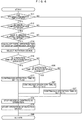
Fig. 6 is a flowchart illustrating a process of selecting a rotation device from compression devices, setting continuous operation times, and performing the start suppression control when the start suppression control is added in the second embodiment. - Hereinafter, embodiments of the present invention will be described with reference to the drawings
- In the present embodiment, an operation number control device for gas compression devices which compress air will be described as an example.
-
Fig. 1 is a system configuration diagram of the operation number control device for the gas compression devices in the present embodiment. InFig. 1 ,compression devices number control device 1 that controls the operating states of the compression devices, and atank 9 that stores compressed gas discharged from the compression devices are schematically configured. The operationnumber control device 1 includes apressure sensor 3 that measures the pressure of the compressed gas stored in thetank 9, acontrol circuit 2 that determines the number of a plurality of the compression devices in operation or the compressor to be operated according to the pressure information, and anoperation switch 4 and astop switch 5 that determine the operating states of all the devices. - When the
operation switch 4 of the operationnumber control device 1 is pressed, the operationnumber control device 1 causes both or one of thecompression devices pressure sensor 3 to measure the pressure of the compressed gas that is discharged from the compression devices and stored in thetank 9, and causes thecontrol circuit 2 to increase or decrease the number of the compression devices in operation and to select a compression device to be operated according to the pressure. - Next,
Fig. 2 is a configuration diagram of an operation number control system of the present invention when agas compression device 7C is added due to an increase in usage amount of the compressed gas in connection with an increase in production capacity of the equipment or the like. InFig. 2 , continuous operation time setting means 20 is newly operated by thecontrol circuit 2.Fig. 3 shows an operation pattern of the gas compression devices at this time. - First, when the
operation switch 4 is pressed to make a request for an operation, thecontrol circuit 2 determines which compression device should be operated before causing the compression device to operate. At this time, since the operation time of thecompression device 7C is the shortest and the operation time of thecompression device 7A is the longest, the order of start of operation is determined to be 7C, 7B, and 7A. The operation time referred to here represents the total operation time which is the sum of operation times from a predetermined time such as when the compression device 7 is produced or sold to the current time. - Next, the continuous operation time setting means 20 determines the continuous operation time of each of the compressors. At this time, the continuous operation time setting means 20 sets the shortest operation time of the compression device to be longer than a standard operation time Tc set in advance, for example, to Tc × 2, and sets the operation time of the compression device having the longest operation time to Tc/2. The continuous operation time referred to here represents the time from the next start of operation of the compression device 7 to the next stop of operation.
- Here, in the present embodiment, the case of three compression devices is described as an example; however, two compression devices or four or more compression devices may be provided, and in that case, the shortest and shortest operation times are set to operation times (two times the standard operation time and a half of the standard operation time) . However, a predetermined coefficient may be set for each of the numbers of the devices according to the operation time, and only the maximum and minimum operation times may be set to values obtained by multiplying the standard operation time Tc by a specific multiplier or divisor.
- Next, the operation of the
compression device 7C is started first, and when the pressure measured by thepressure sensor 3 does not reach pressure set in advance, the operation time of thecompression device 7B having the next shortest operation time is set to the continuous operation time Tc, and thecompression device 7B is started. - Next, when the compressed gas generated and the compressed gas consumed in this state are in balance, the current operation is continued, and when the continuous operation time Tc of the
compression device 7B set in advance has elapsed, a process of determining the switching of the compression device is performed. At this time, since thecompression device 7A is in a standby state, thecontrol circuit 2 determines that rotation can be performed, and again, thecontrol circuit 2 causes thecontinuous operation time 20 to recalculate and set the continuous operation time of each of the compression devices from the operation time of each of the compression devices. - Since the
compression device 7A has the longest operation time among the three compression devices, the operation of thecompression device 7B is stopped at the same time the continuous operation time of thecompression device 7A is set to Tc/2 and thecompression device 7A is started. - Hereinafter, when the continuous operation time of each of the
compression devices - In a case where rotation or operation number control is performed in the control of the compression devices, when two compression devices have reached a predetermined operation time substantially at the same time, there is a case where as shown in
Fig. 4 , thecompression device 7C is operated again as a rotation device for thecompression device 7A immediately after thecompression device 7C is stopped, and thus a sufficient cooling period cannot be secured. At this time, since an operation and a stop operation are performed at a plurality of times for a short time, noise is generated. For this reason, in the present embodiment, even when the compression device has reached a specified operation time set by the continuous operation time setting means 20, in the case of immediately after stop of the rotation device, a function of extending the operation without performing rotation is newly added. - The second embodiment will be described with reference to
Figs. 5 and6 . First, instep 11, the continuous operation time setting means 20 determines whether or not the continuous operation time set in advance of any one of the compression devices in operation has elapsed. In the case of YES, the process proceeds to thenext step 12 and it is determined whether or not there is a compression device at stop. In the case of being determined to be YES, the process proceeds to step 13 and it is determined whether or not a predetermined stop period Th or more set for the compression device at stop has elapsed. In the case of being determined to be YES in step 13, the process proceeds to step 14 and the rotation process is performed, but in the case of being determined to be No in any one ofsteps 11 to 13, the process proceeds tostep 99 and return is performed without the rotation process being performed. - In the next step 14, the total operation times of all the compression devices connected to the operation
number control device 1 are calculated, and the process proceeds tostep 15. - In
step 15, a compression device having the shortest operation time is selected as a rotation device from the compression devices at stop, and the process proceeds tostep 16. - In
step 16, it is determined whether or not the operation time of the rotation device selected is the shortest among the compression devices. In the case of YES, the process proceeds to thenext step 17, the continuous operation time of the rotation device is set to Tc × 2, and the process proceeds tostep 18. In the case of No, the process proceeds to the next step 26. - In step 26, it is determined whether or not the operation time of the rotation device is the longest among the compression devices. In the case of YES, the process proceeds to step 27, the continuous operation time of the rotation device is set to Tc/2, and the process proceeds to step 18. In the case of No, the continuous operation time is set to Tc and the process proceeds to step 18.
- In the
next step 18, a compression device of which the continuous operation time has elapsed is stopped, and the process proceeds to the next step 19. In step 19, the operation of the rotation device is started, the clocking of the continuous operation time determined in the determination process ofstep 16, 26, or 36 is started, the process proceeds to thenext step 99, and return is performed. - Therefore, the operation
number control device 1 determines the continuous operation times of thecompression devices compression devices - In the related art or in the first and second embodiments, the continuous operation time of the compression device is obtained by multiplying the standard operation time by the coefficient set in advance; however, when the total operation times are very much different from each other, it is also considered a case where the leveling of the operation times of the compression devices is not completed until a compression device having the longest total operation time reaches maintenance time. Therefore, in a third embodiment, remaining times Tremain from the total operation times to maintenance of the compression devices each are calculated, an average remaining time Tremain_ave is calculated, and the operation times of the compression devices each are determined from a ratio between the remaining times Tremain and the average remaining time, and thus control can be performed such that the leveling of the total operation times of the compression devices is completed before the compression device having the longest total operation time reaches the maintenance time.
- Specifically, first, Equation (1) is computed to calculate the remaining time Tremain to maintenance of each of the compression devices.
- [Equation 1]

- Here, Tmnt is maintenance time and Tope is the operation time of the compression device.
- Next, the average remaining time Tremain_ave of the entirety of the compression device system is obtained from the remaining times Tremain of the compression devices. Namely, Equation (2) is computed.
- [Equation 2]

- Here, Tremain_7A is the remaining time of the
compression device 7A, Tremain_7B is the remaining time of thecompression device 7B, and Tremain_7c is the remaining time of thecompression device 7C. - Then, a continuous operation time Trun_iong is obtained from the remaining time Tremain and the average remaining time Tremain_ave for a compression device having the shortest operation time. Namely, Equation (3) is computed.
- [Equation 3]

- Here, Trun_iong is the continuous operation time of the compression device having a short operation time, k is an acceleration coefficient, and Tc is the standard continuous operation time.
- However, when the result of the computation of Equation (3) exceeds the maximum operation time assumed for the compression device, the operation time is fixed at a predetermined continuous operation time Trun_max.
- Next, a continuous operation time Trun_short is obtained from the remaining time Tremain and the average remaining time Tremain_ave for a compression device having the longest operation time. The computational equation at this time is expressed as Equation (4).
- [Equation 4]

- However, when the result of the computation of Equation (4) is smaller than the minimum operation time assumed for the compression device, in order to prevent the operation from ending in a very short time, the operation time is fixed at a predetermined continuous operation time Trun_min, so that noise and annoying sound caused by frequent rotation of the compression devices, damage to an electric circuit caused by an inrush current, or contact wear of an electromagnetic contactor is prevented.
- Then, continuous operation times Trun are obtained using Equation (5) for the remaining compression devices.
- [Equation 5]

- Then, Tc × 2, Tc/2, and Tc in
steps 17, 27, and 37 ofFig. 6 are replaced with the continuous operation times Trun, namely, Trun_long, Trun_short, Trun obtained in Equations (3), (4), and (5), and the operation is controlled. - Therefore, according to the present invention, even in the operation number control for a combination of the compression devices having very much different operation times, the compression device having a short operation time can be continuously operated preferentially and for a longer time than the other compression devices, and it is possible to provide the operation number control device and a method for controlling the compression devices that can level the operation times to the maintenance times in the operation number control device for the compression devices.
- In the above embodiments, whether the operation
number control device 1 and the plurality of compression devices 7 are contained in one package as a product or a system in which products contained in a plurality of packages are combined is not particularly limited. Namely, the control described in the above embodiments is performed on the product including the operationnumber control device 1 and the plurality of compression devices 7 in one package, so that for example, when one compression device 7 is replaced due to a failure or when the compression device 7 is added to a space that is empty at the time of sale, the compression devices 7 can be operated such that the operation times of the compression devices 7 are leveled. In addition, when the compression device 7 which is a package type is newly added to an environment where one or more compression devices 7 which are a package type are already operated, or the like, the operationnumber control device 1 which is a package type can be introduced to cause the compression devices 7 to operate such that the operation times of the compression devices 7 are leveled. - Particularly, in the case of a system in which the operation
number control device 1 and the plurality of compression devices 7 are all formed as separate products, each of the compression devices 7 includes a control substrate, but is configured to operate as described in the present embodiments according to an operation or stop signal or the like from thecontrol circuit 2 provided in the operationnumber control device 1. In addition, each of the compression devices 7 may be configured to transmit a current operating status or information regarding operation time via a communication line through which a start or stop signal and the like from the operationnumber control device 1 are received. The operationnumber control device 1 may be configured to count the operation time of each of the compression devices 7 based on the premise that a user inputs the operation time of each of the compression devices 7 into the operationnumber control device 1 during construction of the system and each of thecompression devices 1 operates according to a start or stop signal from the operationnumber control device 1 after the system is constructed. - Incidentally, the present invention can be adopted in a compression device system or in a package of compression devices including a plurality of compression devices such as a twin or single screw type, a reciprocating type, or a turbo type. In addition, the present invention can also be adopted in a compression device that compresses a mixed gas such as air or a compression device that compresses a single gas such as nitrogen gas or oxygen gas, as the compression device. Further, the present invention can be adopted in a system or package including a plurality of fluid machines such as chillers or pumps including the same mechanism, other than the compression device.
- Incidentally, the present invention is not limited to the above-described embodiments, and includes various modification examples. For example, the above-described embodiments have been described in detail to describe the present invention in an easy-to-understand manner, and the present invention is not necessarily limited to including all the configurations described. In addition, a part of the configuration of an embodiment can be replaced with the configuration of another embodiment, and the configuration of another embodiment can be added to the configuration of an embodiment. In addition, other configurations can be added to, removed from, or replaced with a part of the configuration of each of the embodiments.
-
- 1
- Operation number control device
- 2
- Control circuit
- 3
- Pressure sensor
- 4
- Operation switch
- 5
- Stop switch
- 7
- Compression device
- 9
- Air tank
- 20
- Continuous operation time setting means
Claims (10)
- A fluid machine system comprising:a plurality of fluid machines; andan operation number control device capable of individually controlling start and stop of the fluid machines,wherein the operation number control device sets a continuous operation time for each of the fluid machines based on total operation times of the fluid machine and other fluid machines, andwhen among fluid machines in operation, there is a fluid machine for which the continuous operation time set for the fluid machine has elapsed and there is a fluid machine at stop, the operation number control device causes the fluid machine at stop to start and causes the fluid machine to stop.
- The fluid machine system according to claim 1,
wherein when among the fluid machines in operation, there is the fluid machine for which the continuous operation time set for the fluid machine has elapsed, and when there is the fluid machine at stop and an elapsed time from stop of the fluid machine at stop is shorter than a predetermined time, the operation number control device causes the fluid machine at stop to start after the predetermined time has elapsed, and causes the fluid machine to stop. - The fluid machine system according to claim 1,
wherein in setting the continuous operation time of each of the fluid machines, the operation number control device sets the continuous operation time of a fluid machine having a long total operation time to a time shorter than the continuous operation time of a fluid machine having a short total operation time. - The fluid machine system according to claim 3,
wherein in setting the continuous operation time of each of the fluid machines, the operation number control device sets the continuous operation time of each of the fluid machines before a fluid machine having a longest total operation time reaches a maintenance time. - The fluid machine system according to claim 1,
wherein when the fluid machine system starts, the operation number control device causes a fluid machine having a longest continuous operation time to start first. - A method for controlling a fluid machine system, the method comprising:setting a continuous operation time for each of a plurality of fluid machines based on total operation times of the fluid machine and other fluid machines, andcausing a fluid machine at stop to start and causing the fluid machine to stop when among fluid machines in operation, there is a fluid machine for which the continuous operation time set for the fluid machine has elapsed and there is a fluid machine at stop.
- The method for controlling a fluid machine system according to claim 6,
wherein when among the fluid machines in operation, there is the fluid machine for which the continuous operation time set for the fluid machine has elapsed, and when there is the fluid machine at stop and an elapsed time from stop of the fluid machine at stop is shorter than a predetermined time, the fluid machine at stop is started after the predetermined time has elapsed, and the fluid machine is stopped. - The method for controlling a fluid machine system according to claim 6,
wherein in setting the continuous operation time of each of the fluid machines, the continuous operation time of a fluid machine having a long total operation time is set to a time shorter than the continuous operation time of a fluid machine having a short total operation time. - The method for controlling a fluid machine system according to claim 8,
wherein in setting the continuous operation time of each of the fluid machines, the continuous operation time of each of the fluid machines is set before a fluid machine having a longest total operation time reaches a maintenance time. - The method for controlling a fluid machine system according to claim 6,
wherein when the fluid machine system starts, a fluid machine having a longest continuous operation time is started first.
Applications Claiming Priority (2)
| Application Number | Priority Date | Filing Date | Title |
|---|---|---|---|
| JP2018237869A JP7261579B2 (en) | 2018-12-20 | 2018-12-20 | Fluid mechanical system and its control method |
| PCT/JP2019/046725 WO2020129572A1 (en) | 2018-12-20 | 2019-11-29 | Fluid machinery system and method for controlling same |
Publications (3)
| Publication Number | Publication Date |
|---|---|
| EP3901460A1 true EP3901460A1 (en) | 2021-10-27 |
| EP3901460A4 EP3901460A4 (en) | 2022-08-10 |
| EP3901460B1 EP3901460B1 (en) | 2024-07-17 |
Family
ID=71101160
Family Applications (1)
| Application Number | Title | Priority Date | Filing Date |
|---|---|---|---|
| EP19899756.1A Active EP3901460B1 (en) | 2018-12-20 | 2019-11-29 | Fluid machine system and method for controlling same |
Country Status (5)
| Country | Link |
|---|---|
| US (1) | US12044232B2 (en) |
| EP (1) | EP3901460B1 (en) |
| JP (1) | JP7261579B2 (en) |
| CN (1) | CN112368479B (en) |
| WO (1) | WO2020129572A1 (en) |
Families Citing this family (5)
| Publication number | Priority date | Publication date | Assignee | Title |
|---|---|---|---|---|
| DE102020203755A1 (en) * | 2020-03-24 | 2021-09-30 | Bauer Kompressoren Gmbh | FILTER UNIT FOR A COMPRESSOR |
| JP2022085322A (en) * | 2020-11-27 | 2022-06-08 | 株式会社クボタ | Operation control method |
| JP7568565B2 (en) * | 2021-03-30 | 2024-10-16 | 株式会社日立産機システム | Gas Compression System |
| BE1029908B1 (en) * | 2021-11-08 | 2023-06-05 | Atlas Copco Airpower Nv | METHOD AND METHOD FOR REMOTE MANAGEMENT OF A COMPRESSED AIR DISTRIBUTION SYSTEM |
| US12338810B1 (en) * | 2024-02-05 | 2025-06-24 | Dongguan Hesheng Machinery & Electric Co., Ltd. | Inflation control system having multiple air compressors |
Family Cites Families (17)
| Publication number | Priority date | Publication date | Assignee | Title |
|---|---|---|---|---|
| JPS58161011A (en) | 1982-03-19 | 1983-09-24 | Toshiba Corp | Method for controlling number of operated pumps |
| US4502842A (en) * | 1983-02-02 | 1985-03-05 | Colt Industries Operating Corp. | Multiple compressor controller and method |
| US5190442A (en) * | 1991-09-06 | 1993-03-02 | Jorritsma Johannes N | Electronic pumpcontrol system |
| JP4258522B2 (en) | 2000-09-05 | 2009-04-30 | トヨタ自動車株式会社 | Electric oil pump control device |
| JP3867521B2 (en) | 2000-09-05 | 2007-01-10 | トヨタ自動車株式会社 | Electric oil pump control device |
| JP2003029802A (en) | 2001-07-18 | 2003-01-31 | Toshiba Corp | Operating time control device |
| JP4098154B2 (en) * | 2003-05-15 | 2008-06-11 | アネスト岩田株式会社 | Management method of maintenance timing in gas compressor assembly system |
| CN1940294B (en) * | 2005-09-30 | 2011-06-01 | 株式会社日立制作所 | Controls for air compressors |
| JP2007291857A (en) | 2006-04-20 | 2007-11-08 | Nidec Sankyo Corp | Metering pump device |
| JP5094156B2 (en) | 2007-02-22 | 2012-12-12 | 株式会社日立産機システム | Water supply equipment |
| JP2009133253A (en) | 2007-11-30 | 2009-06-18 | Mitsubishi Electric Corp | Pump operation control system |
| CN101660529B (en) | 2008-08-29 | 2011-06-08 | 上海斯可络压缩机有限公司 | On-line control method of screw compressor |
| JP2011038434A (en) | 2009-08-07 | 2011-02-24 | Mitsui Seiki Kogyo Co Ltd | Operation control method for a plurality of compressors composed of simultaneous use of the same form, commercial machine and inverter machine, simultaneous use of commercial machine and always fixed commercial machine and simultaneous use of commercial machine, inverter machine and always fixed commercial machine |
| JP5464247B1 (en) * | 2012-09-26 | 2014-04-09 | ダイキン工業株式会社 | Control device |
| CN104968939B (en) | 2013-02-08 | 2018-01-09 | 株式会社日立产机系统 | Fluid compression system and its control device |
| CN105222265B (en) | 2014-06-23 | 2018-05-25 | 青岛海尔空调电子有限公司 | The outer machine balanced running control method of VRF Air Conditioning System and VRF Air Conditioning System |
| JP5996677B2 (en) | 2015-01-05 | 2016-09-21 | 株式会社Ihi回転機械 | Compressor number control device |
-
2018
- 2018-12-20 JP JP2018237869A patent/JP7261579B2/en active Active
-
2019
- 2019-11-29 US US17/274,700 patent/US12044232B2/en active Active
- 2019-11-29 CN CN201980043786.6A patent/CN112368479B/en active Active
- 2019-11-29 WO PCT/JP2019/046725 patent/WO2020129572A1/en not_active Ceased
- 2019-11-29 EP EP19899756.1A patent/EP3901460B1/en active Active
Also Published As
| Publication number | Publication date |
|---|---|
| JP7261579B2 (en) | 2023-04-20 |
| WO2020129572A1 (en) | 2020-06-25 |
| US20220049691A1 (en) | 2022-02-17 |
| US12044232B2 (en) | 2024-07-23 |
| EP3901460A4 (en) | 2022-08-10 |
| CN112368479B (en) | 2022-10-25 |
| CN112368479A (en) | 2021-02-12 |
| JP2020101094A (en) | 2020-07-02 |
| EP3901460B1 (en) | 2024-07-17 |
Similar Documents
| Publication | Publication Date | Title |
|---|---|---|
| EP3901460B1 (en) | Fluid machine system and method for controlling same | |
| CN104295477B (en) | The integrating control operation method of multiple air compressors | |
| CN106155797B (en) | Terminal equipment and switching method of performance modes thereof | |
| US8478551B2 (en) | Systems and methods of profiling power cycles in a battery for indicating detrimental battery operation | |
| CN106950448A (en) | Device and method for life detection of relay protection device | |
| US7252483B2 (en) | Method of managing time, at which maintenance in a gas compressor multiple system should be carried out | |
| KR101389793B1 (en) | Apparatus and method for monitoring and analyzing motor | |
| JP2010208770A (en) | Group supervisory operation system of elevator | |
| JP2013194628A (en) | Air compressor control method and air compressor control system | |
| EP1768431A1 (en) | Network selection for a multimode terminal. | |
| JP3555884B2 (en) | Battery life determining method and device | |
| JP5798405B2 (en) | Method and apparatus for forcibly switching compressor equipment | |
| US20210293231A1 (en) | Air compressor | |
| JP2002359673A (en) | Portable communication terminal and power management method for the portable communication terminal | |
| JP4170596B2 (en) | Control device and radio device | |
| JP2005156303A (en) | Battery capacity determining apparatus | |
| JP5504214B2 (en) | Gas compression device | |
| JPH08296565A (en) | Control device for the number of compressors | |
| Facchinetti et al. | Modeling and real-time control of an industrial air multi-compressor system | |
| KR101055054B1 (en) | Battery remaining capacity alarm method of mobile communication terminal | |
| KR20200092686A (en) | Linear compressor and method for controlling linear compressor | |
| JPH08300433A (en) | Control device of hydraulic mechanism in injection molding machine | |
| WO2025052787A1 (en) | Compressor and method for monitoring compressor | |
| KR20130129697A (en) | Multiple compressor control system and method of controlling the same | |
| JP2023517646A (en) | Pump speed control method and apparatus, computer program, computer readable medium storing computer program adapted thereto, and pump |
Legal Events
| Date | Code | Title | Description |
|---|---|---|---|
| STAA | Information on the status of an ep patent application or granted ep patent |
Free format text: STATUS: THE INTERNATIONAL PUBLICATION HAS BEEN MADE |
|
| PUAI | Public reference made under article 153(3) epc to a published international application that has entered the european phase |
Free format text: ORIGINAL CODE: 0009012 |
|
| STAA | Information on the status of an ep patent application or granted ep patent |
Free format text: STATUS: REQUEST FOR EXAMINATION WAS MADE |
|
| 17P | Request for examination filed |
Effective date: 20210720 |
|
| AK | Designated contracting states |
Kind code of ref document: A1 Designated state(s): AL AT BE BG CH CY CZ DE DK EE ES FI FR GB GR HR HU IE IS IT LI LT LU LV MC MK MT NL NO PL PT RO RS SE SI SK SM TR |
|
| DAV | Request for validation of the european patent (deleted) | ||
| DAX | Request for extension of the european patent (deleted) | ||
| REG | Reference to a national code |
Ref legal event code: R079 Ref country code: DE Ref document number: 602019055536 Country of ref document: DE Free format text: PREVIOUS MAIN CLASS: F04B0049060000 Ipc: F04B0041020000 |
|
| A4 | Supplementary search report drawn up and despatched |
Effective date: 20220708 |
|
| RIC1 | Information provided on ipc code assigned before grant |
Ipc: F04B 49/08 20060101ALI20220704BHEP Ipc: F04B 49/06 20060101ALI20220704BHEP Ipc: F04B 49/02 20060101ALI20220704BHEP Ipc: F04B 41/06 20060101ALI20220704BHEP Ipc: F04B 41/02 20060101AFI20220704BHEP |
|
| GRAP | Despatch of communication of intention to grant a patent |
Free format text: ORIGINAL CODE: EPIDOSNIGR1 |
|
| STAA | Information on the status of an ep patent application or granted ep patent |
Free format text: STATUS: GRANT OF PATENT IS INTENDED |
|
| INTG | Intention to grant announced |
Effective date: 20240219 |
|
| GRAS | Grant fee paid |
Free format text: ORIGINAL CODE: EPIDOSNIGR3 |
|
| GRAA | (expected) grant |
Free format text: ORIGINAL CODE: 0009210 |
|
| STAA | Information on the status of an ep patent application or granted ep patent |
Free format text: STATUS: THE PATENT HAS BEEN GRANTED |
|
| AK | Designated contracting states |
Kind code of ref document: B1 Designated state(s): AL AT BE BG CH CY CZ DE DK EE ES FI FR GB GR HR HU IE IS IT LI LT LU LV MC MK MT NL NO PL PT RO RS SE SI SK SM TR |
|
| REG | Reference to a national code |
Ref country code: CH Ref legal event code: EP |
|
| REG | Reference to a national code |
Ref country code: DE Ref legal event code: R096 Ref document number: 602019055536 Country of ref document: DE |
|
| REG | Reference to a national code |
Ref country code: IE Ref legal event code: FG4D |
|
| REG | Reference to a national code |
Ref country code: LT Ref legal event code: MG9D |
|
| REG | Reference to a national code |
Ref country code: NL Ref legal event code: MP Effective date: 20240717 |
|
| PG25 | Lapsed in a contracting state [announced via postgrant information from national office to epo] |
Ref country code: PT Free format text: LAPSE BECAUSE OF FAILURE TO SUBMIT A TRANSLATION OF THE DESCRIPTION OR TO PAY THE FEE WITHIN THE PRESCRIBED TIME-LIMIT Effective date: 20241118 |
|
| REG | Reference to a national code |
Ref country code: AT Ref legal event code: MK05 Ref document number: 1704373 Country of ref document: AT Kind code of ref document: T Effective date: 20240717 |
|
| PG25 | Lapsed in a contracting state [announced via postgrant information from national office to epo] |
Ref country code: NL Free format text: LAPSE BECAUSE OF FAILURE TO SUBMIT A TRANSLATION OF THE DESCRIPTION OR TO PAY THE FEE WITHIN THE PRESCRIBED TIME-LIMIT Effective date: 20240717 |
|
| PG25 | Lapsed in a contracting state [announced via postgrant information from national office to epo] |
Ref country code: PT Free format text: LAPSE BECAUSE OF FAILURE TO SUBMIT A TRANSLATION OF THE DESCRIPTION OR TO PAY THE FEE WITHIN THE PRESCRIBED TIME-LIMIT Effective date: 20241118 Ref country code: NL Free format text: LAPSE BECAUSE OF FAILURE TO SUBMIT A TRANSLATION OF THE DESCRIPTION OR TO PAY THE FEE WITHIN THE PRESCRIBED TIME-LIMIT Effective date: 20240717 |
|
| PG25 | Lapsed in a contracting state [announced via postgrant information from national office to epo] |
Ref country code: NO Free format text: LAPSE BECAUSE OF FAILURE TO SUBMIT A TRANSLATION OF THE DESCRIPTION OR TO PAY THE FEE WITHIN THE PRESCRIBED TIME-LIMIT Effective date: 20241017 |
|
| PG25 | Lapsed in a contracting state [announced via postgrant information from national office to epo] |
Ref country code: GR Free format text: LAPSE BECAUSE OF FAILURE TO SUBMIT A TRANSLATION OF THE DESCRIPTION OR TO PAY THE FEE WITHIN THE PRESCRIBED TIME-LIMIT Effective date: 20241018 Ref country code: FI Free format text: LAPSE BECAUSE OF FAILURE TO SUBMIT A TRANSLATION OF THE DESCRIPTION OR TO PAY THE FEE WITHIN THE PRESCRIBED TIME-LIMIT Effective date: 20240717 Ref country code: PL Free format text: LAPSE BECAUSE OF FAILURE TO SUBMIT A TRANSLATION OF THE DESCRIPTION OR TO PAY THE FEE WITHIN THE PRESCRIBED TIME-LIMIT Effective date: 20240717 |
|
| PG25 | Lapsed in a contracting state [announced via postgrant information from national office to epo] |
Ref country code: BG Free format text: LAPSE BECAUSE OF FAILURE TO SUBMIT A TRANSLATION OF THE DESCRIPTION OR TO PAY THE FEE WITHIN THE PRESCRIBED TIME-LIMIT Effective date: 20240717 |
|
| PG25 | Lapsed in a contracting state [announced via postgrant information from national office to epo] |
Ref country code: LV Free format text: LAPSE BECAUSE OF FAILURE TO SUBMIT A TRANSLATION OF THE DESCRIPTION OR TO PAY THE FEE WITHIN THE PRESCRIBED TIME-LIMIT Effective date: 20240717 |
|
| PG25 | Lapsed in a contracting state [announced via postgrant information from national office to epo] |
Ref country code: IS Free format text: LAPSE BECAUSE OF FAILURE TO SUBMIT A TRANSLATION OF THE DESCRIPTION OR TO PAY THE FEE WITHIN THE PRESCRIBED TIME-LIMIT Effective date: 20241117 Ref country code: AT Free format text: LAPSE BECAUSE OF FAILURE TO SUBMIT A TRANSLATION OF THE DESCRIPTION OR TO PAY THE FEE WITHIN THE PRESCRIBED TIME-LIMIT Effective date: 20240717 |
|
| PG25 | Lapsed in a contracting state [announced via postgrant information from national office to epo] |
Ref country code: HR Free format text: LAPSE BECAUSE OF FAILURE TO SUBMIT A TRANSLATION OF THE DESCRIPTION OR TO PAY THE FEE WITHIN THE PRESCRIBED TIME-LIMIT Effective date: 20240717 |
|
| PG25 | Lapsed in a contracting state [announced via postgrant information from national office to epo] |
Ref country code: RS Free format text: LAPSE BECAUSE OF FAILURE TO SUBMIT A TRANSLATION OF THE DESCRIPTION OR TO PAY THE FEE WITHIN THE PRESCRIBED TIME-LIMIT Effective date: 20241017 Ref country code: ES Free format text: LAPSE BECAUSE OF FAILURE TO SUBMIT A TRANSLATION OF THE DESCRIPTION OR TO PAY THE FEE WITHIN THE PRESCRIBED TIME-LIMIT Effective date: 20240717 |
|
| PG25 | Lapsed in a contracting state [announced via postgrant information from national office to epo] |
Ref country code: RS Free format text: LAPSE BECAUSE OF FAILURE TO SUBMIT A TRANSLATION OF THE DESCRIPTION OR TO PAY THE FEE WITHIN THE PRESCRIBED TIME-LIMIT Effective date: 20241017 Ref country code: PL Free format text: LAPSE BECAUSE OF FAILURE TO SUBMIT A TRANSLATION OF THE DESCRIPTION OR TO PAY THE FEE WITHIN THE PRESCRIBED TIME-LIMIT Effective date: 20240717 Ref country code: NO Free format text: LAPSE BECAUSE OF FAILURE TO SUBMIT A TRANSLATION OF THE DESCRIPTION OR TO PAY THE FEE WITHIN THE PRESCRIBED TIME-LIMIT Effective date: 20241017 Ref country code: LV Free format text: LAPSE BECAUSE OF FAILURE TO SUBMIT A TRANSLATION OF THE DESCRIPTION OR TO PAY THE FEE WITHIN THE PRESCRIBED TIME-LIMIT Effective date: 20240717 Ref country code: IS Free format text: LAPSE BECAUSE OF FAILURE TO SUBMIT A TRANSLATION OF THE DESCRIPTION OR TO PAY THE FEE WITHIN THE PRESCRIBED TIME-LIMIT Effective date: 20241117 Ref country code: HR Free format text: LAPSE BECAUSE OF FAILURE TO SUBMIT A TRANSLATION OF THE DESCRIPTION OR TO PAY THE FEE WITHIN THE PRESCRIBED TIME-LIMIT Effective date: 20240717 Ref country code: GR Free format text: LAPSE BECAUSE OF FAILURE TO SUBMIT A TRANSLATION OF THE DESCRIPTION OR TO PAY THE FEE WITHIN THE PRESCRIBED TIME-LIMIT Effective date: 20241018 Ref country code: FI Free format text: LAPSE BECAUSE OF FAILURE TO SUBMIT A TRANSLATION OF THE DESCRIPTION OR TO PAY THE FEE WITHIN THE PRESCRIBED TIME-LIMIT Effective date: 20240717 Ref country code: ES Free format text: LAPSE BECAUSE OF FAILURE TO SUBMIT A TRANSLATION OF THE DESCRIPTION OR TO PAY THE FEE WITHIN THE PRESCRIBED TIME-LIMIT Effective date: 20240717 Ref country code: BG Free format text: LAPSE BECAUSE OF FAILURE TO SUBMIT A TRANSLATION OF THE DESCRIPTION OR TO PAY THE FEE WITHIN THE PRESCRIBED TIME-LIMIT Effective date: 20240717 Ref country code: AT Free format text: LAPSE BECAUSE OF FAILURE TO SUBMIT A TRANSLATION OF THE DESCRIPTION OR TO PAY THE FEE WITHIN THE PRESCRIBED TIME-LIMIT Effective date: 20240717 |
|
| PG25 | Lapsed in a contracting state [announced via postgrant information from national office to epo] |
Ref country code: RO Free format text: LAPSE BECAUSE OF FAILURE TO SUBMIT A TRANSLATION OF THE DESCRIPTION OR TO PAY THE FEE WITHIN THE PRESCRIBED TIME-LIMIT Effective date: 20240717 Ref country code: SM Free format text: LAPSE BECAUSE OF FAILURE TO SUBMIT A TRANSLATION OF THE DESCRIPTION OR TO PAY THE FEE WITHIN THE PRESCRIBED TIME-LIMIT Effective date: 20240717 Ref country code: DK Free format text: LAPSE BECAUSE OF FAILURE TO SUBMIT A TRANSLATION OF THE DESCRIPTION OR TO PAY THE FEE WITHIN THE PRESCRIBED TIME-LIMIT Effective date: 20240717 |
|
| REG | Reference to a national code |
Ref country code: DE Ref legal event code: R097 Ref document number: 602019055536 Country of ref document: DE |
|
| PG25 | Lapsed in a contracting state [announced via postgrant information from national office to epo] |
Ref country code: EE Free format text: LAPSE BECAUSE OF FAILURE TO SUBMIT A TRANSLATION OF THE DESCRIPTION OR TO PAY THE FEE WITHIN THE PRESCRIBED TIME-LIMIT Effective date: 20240717 |
|
| PG25 | Lapsed in a contracting state [announced via postgrant information from national office to epo] |
Ref country code: CZ Free format text: LAPSE BECAUSE OF FAILURE TO SUBMIT A TRANSLATION OF THE DESCRIPTION OR TO PAY THE FEE WITHIN THE PRESCRIBED TIME-LIMIT Effective date: 20240717 |
|
| PG25 | Lapsed in a contracting state [announced via postgrant information from national office to epo] |
Ref country code: SK Free format text: LAPSE BECAUSE OF FAILURE TO SUBMIT A TRANSLATION OF THE DESCRIPTION OR TO PAY THE FEE WITHIN THE PRESCRIBED TIME-LIMIT Effective date: 20240717 |
|
| PLBE | No opposition filed within time limit |
Free format text: ORIGINAL CODE: 0009261 |
|
| STAA | Information on the status of an ep patent application or granted ep patent |
Free format text: STATUS: NO OPPOSITION FILED WITHIN TIME LIMIT |
|
| 26N | No opposition filed |
Effective date: 20250422 |
|
| REG | Reference to a national code |
Ref country code: CH Ref legal event code: PL |
|
| PG25 | Lapsed in a contracting state [announced via postgrant information from national office to epo] |
Ref country code: MC Free format text: LAPSE BECAUSE OF FAILURE TO SUBMIT A TRANSLATION OF THE DESCRIPTION OR TO PAY THE FEE WITHIN THE PRESCRIBED TIME-LIMIT Effective date: 20240717 |
|
| PG25 | Lapsed in a contracting state [announced via postgrant information from national office to epo] |
Ref country code: LU Free format text: LAPSE BECAUSE OF NON-PAYMENT OF DUE FEES Effective date: 20241129 |
|
| REG | Reference to a national code |
Ref country code: CH Ref legal event code: PL |
|
| PG25 | Lapsed in a contracting state [announced via postgrant information from national office to epo] |
Ref country code: CH Free format text: LAPSE BECAUSE OF NON-PAYMENT OF DUE FEES Effective date: 20241130 |
|
| PG25 | Lapsed in a contracting state [announced via postgrant information from national office to epo] |
Ref country code: SE Free format text: LAPSE BECAUSE OF FAILURE TO SUBMIT A TRANSLATION OF THE DESCRIPTION OR TO PAY THE FEE WITHIN THE PRESCRIBED TIME-LIMIT Effective date: 20240717 |
|
| PG25 | Lapsed in a contracting state [announced via postgrant information from national office to epo] |
Ref country code: IE Free format text: LAPSE BECAUSE OF NON-PAYMENT OF DUE FEES Effective date: 20241129 |
|
| PGFP | Annual fee paid to national office [announced via postgrant information from national office to epo] |
Ref country code: DE Payment date: 20251130 Year of fee payment: 7 |
|
| PGFP | Annual fee paid to national office [announced via postgrant information from national office to epo] |
Ref country code: GB Payment date: 20251120 Year of fee payment: 7 |
|
| PGFP | Annual fee paid to national office [announced via postgrant information from national office to epo] |
Ref country code: FR Payment date: 20251120 Year of fee payment: 7 |
|
| PGFP | Annual fee paid to national office [announced via postgrant information from national office to epo] |
Ref country code: BE Payment date: 20251118 Year of fee payment: 7 |
|
| PG25 | Lapsed in a contracting state [announced via postgrant information from national office to epo] |
Ref country code: IT Free format text: LAPSE BECAUSE OF FAILURE TO SUBMIT A TRANSLATION OF THE DESCRIPTION OR TO PAY THE FEE WITHIN THE PRESCRIBED TIME-LIMIT Effective date: 20240717 |
|
| PG25 | Lapsed in a contracting state [announced via postgrant information from national office to epo] |
Ref country code: HU Free format text: LAPSE BECAUSE OF FAILURE TO SUBMIT A TRANSLATION OF THE DESCRIPTION OR TO PAY THE FEE WITHIN THE PRESCRIBED TIME-LIMIT; INVALID AB INITIO Effective date: 20191129 |
|
| PG25 | Lapsed in a contracting state [announced via postgrant information from national office to epo] |
Ref country code: CY Free format text: LAPSE BECAUSE OF FAILURE TO SUBMIT A TRANSLATION OF THE DESCRIPTION OR TO PAY THE FEE WITHIN THE PRESCRIBED TIME-LIMIT; INVALID AB INITIO Effective date: 20191129 |