EP3901446A1 - Recoil stator rope reel and recoil stator - Google Patents
Recoil stator rope reel and recoil stator Download PDFInfo
- Publication number
- EP3901446A1 EP3901446A1 EP20745294.7A EP20745294A EP3901446A1 EP 3901446 A1 EP3901446 A1 EP 3901446A1 EP 20745294 A EP20745294 A EP 20745294A EP 3901446 A1 EP3901446 A1 EP 3901446A1
- Authority
- EP
- European Patent Office
- Prior art keywords
- rope
- reel
- rope reel
- arch portion
- arch
- Prior art date
- Legal status (The legal status is an assumption and is not a legal conclusion. Google has not performed a legal analysis and makes no representation as to the accuracy of the status listed.)
- Granted
Links
Images


Classifications
-
- F—MECHANICAL ENGINEERING; LIGHTING; HEATING; WEAPONS; BLASTING
- F02—COMBUSTION ENGINES; HOT-GAS OR COMBUSTION-PRODUCT ENGINE PLANTS
- F02N—STARTING OF COMBUSTION ENGINES; STARTING AIDS FOR SUCH ENGINES, NOT OTHERWISE PROVIDED FOR
- F02N3/00—Other muscle-operated starting apparatus
- F02N3/02—Other muscle-operated starting apparatus having pull-cords
-
- F—MECHANICAL ENGINEERING; LIGHTING; HEATING; WEAPONS; BLASTING
- F02—COMBUSTION ENGINES; HOT-GAS OR COMBUSTION-PRODUCT ENGINE PLANTS
- F02N—STARTING OF COMBUSTION ENGINES; STARTING AIDS FOR SUCH ENGINES, NOT OTHERWISE PROVIDED FOR
- F02N15/00—Other power-operated starting apparatus; Component parts, details, or accessories, not provided for in, or of interest apart from groups F02N5/00 - F02N13/00
- F02N15/006—Assembling or mounting of starting devices
-
- F—MECHANICAL ENGINEERING; LIGHTING; HEATING; WEAPONS; BLASTING
- F02—COMBUSTION ENGINES; HOT-GAS OR COMBUSTION-PRODUCT ENGINE PLANTS
- F02N—STARTING OF COMBUSTION ENGINES; STARTING AIDS FOR SUCH ENGINES, NOT OTHERWISE PROVIDED FOR
- F02N5/00—Starting apparatus having mechanical power storage
- F02N5/02—Starting apparatus having mechanical power storage of spring type
Definitions
- the present disclosure relates to a recoil starter capable of applying a starting rotational force to an engine by pulling a rope.
- a recoil starter in which a rope reel is rotated by pulling a rope wound around the rope reel, and the rotation of the rope reel is transmitted to a rotation member coupled to a crankshaft of an engine, and the crankshaft of the engine is rotated by the rotation member to start the engine.
- An end of the rope wound around the rope reel is pulled out to an outside of a case so that one of ends of the rope can be pulled, and the other end of the rope is attached to the rope reel.
- the end of the rope attached to the rope reel is locked to a side surface of the rope reel by forming a knot.
- the knot of the rope is not fixed to a side of a starter case covering the rope reel but to a side surface of the rope reel on an engine side. According to the above configuration, since there is no need to provide a gap for holding the knot of the rope between the rope reel and the starter case covering the rope reel, the starter case and the rope reel can be disposed as close as possible to each other. Therefore, a width of the recoil starter can be reduced as much as possible, and the recoil starter can be made compact.
- a method of sandwiching the front end portion of the rope near the knot can be considered.
- the front end portion sandwiched near the knot may come off due to loosening of the rope.
- a method of fixing the front end portion of the rope by means of an adhesive or the like may be considered.
- the front end portion of the rope is fixed by means of an adhesive or the like, there is a problem that the rope cannot be replaced.
- the present disclosure is to provide a rope reel for a recoil starter in which a front end portion of a rope does not interfere with a rotation member on an engine side and the rope is easily replaced. Further, the present disclosure also relates to an end of a rope wound around the rope reel for a recoil starter.
- a rope reel provided in a recoil starter includes a rope holding groove configured such that a rope is wound around the rope holding groove, a flange portion disposed on both sides of the rope holding groove, a through hole provided in the flange portion and configured to allow an end of the rope wound around the rope holding groove to pass through, and an arch portion provided on a side surface of the rope reel and adjacent to the through hole.
- the arch portion is configured such that the rope is inserted in the arch portion, and the arch portion is capable of holding the inserted rope along the side surface of the rope reel.
- the rope reel for a recoil starter includes the through hole provided in the flange portion so as to allow the end of the rope wound around the rope holding groove to pass therethrough, and the arch portion provided on the side surface of the rope reel and adjacent to the through hole, and the rope can be inserted through the arch portion and the arch portion can hold the inserted rope along the side surface of the rope reel.
- the rope reel can be disposed close to the rotation member, and the degree of freedom in layout can be increased. For example, a width of the recoil starter can be reduced and the recoil starter can be reduced in size. Further, since the rope can be removed simply by pulling out the rope from the arch portion, the rope can be easily replaced.
- a recoil starter 10 starts an engine by applying a rotational force to an engine crankshaft 42.
- the recoil starter 10 includes a starter case 11, a rope reel 20, a ratchet member 40, a drive pulley 41, and the like.
- the starter case 11 is disposed so as to cover a side surface portion of the engine while accommodating main components of the recoil starter 10.
- a reel support shaft 11a protruding inward so as to face the engine crankshaft 42 is provided.
- the rope reel 20 to be described later is rotatably attached to the reel support shaft 11a.
- the rope reel 20 is a wheel-shaped member, and includes a rope holding groove 21 configured such that a rope 30 is wound around the rope reel 20.
- the reel support shaft 11a passes through a hole formed in a central portion of the rope reel 20, and thus the rope reel 20 is rotatably attached to the reel support shaft 11a.
- One end of the rope 30 wound around the rope reel 20 is fixed to the rope reel 20, and the other end of the rope 30 is drawn out to an outside of the starter case 11. Therefore, the rope reel 20 is configured to rotate around the reel support shaft 11a by an operator vigorously pulling the drawn out rope 30.
- the rope reel 20 When the operator releases the drawn out rope 30, the rope reel 20 is reversely rotated by a return spring, and the rope 30 is automatically wound up.
- the return spring is a spiral spring, and one end of the return spring is fixed to the starter case 11 and the other end is fixed to the rope reel 20.
- a rotational force is accumulated in the return spring.
- the rope reel 20 is reversely rotated due to the spring force accumulated in the return spring, and the rope reel 20 winds up the rope 30.
- the ratchet member 40 is attached to the rope reel 20 so as to rotate integrally with the rope reel 20.
- the ratchet member 40 is swingably attached to a side surface of the rope reel 20, and the ratchet member 40 is formed so as to engage with an inner peripheral surface of a drive pulley 41 to be described later, by swinging the ratchet member 40. Since a structure in the related art may be applied to the ratchet member 40, although a configuration of the ratchet member 40 is not described in detail, the ratchet member 40 is configured to engage with the drive pulley 41 only when the rope reel 20 attempts to rotate in a predetermined direction (a direction in which the engine is started) with respect to the drive pulley 41.
- the ratchet member 40 swings to engage with the drive pulley 41, and the rotational force of the rope reel 20 is transmitted to the drive pulley 41. Meanwhile, when the rope reel 20 is rotating in a winding direction of the rope 30 or when the rope reel 20 is not rotating, the ratchet member 40 swings in a retracting direction and does not engage with the drive pulley 41. As a result, the rope reel 20 and the drive pulley 41 do not transmit rotational force to each other.
- the drive pulley 41 is a tubular member and is connected to the engine crankshaft 42.
- the drive pulley 41 is rotatably supported coaxially with the rotation shaft (reel support shaft 11a) of the rope reel 20.
- the engine crankshaft 42 integrally coupled to the drive pulley 41 rotates, and a starting rotational force is applied to the engine.
- a rotation member 43 that rotates integrally with the engine crankshaft 42 is attached to the engine crankshaft 42 according to the present embodiment.
- a rotation member 43 having a fan shape for blowing air to the engine is attached.
- an end of the rope 30 attached to the rope reel 20 is locked to a side surface of the rope reel 20 by forming a knot 30b.
- the knot 30b of the rope 30 is fixed to a side surface of the rope reel 20 disposed on an engine side. According to the above configuration, there is no need to provide a gap for holding the knot 30b of the rope 30 between the starter case 11 covering the rope reel 20 and the rope reel 20, so that the starter case 11 and the rope reel 20 can be disposed as close as possible to each other. Therefore, a width of the recoil starter 10 can be reduced as much as possible.
- the rope reel 20 can hold the end of the rope 30, and is formed so as to prevent interference between the rotation member 43 and the front end portion 30a of the rope 30.
- the rope reel 20 includes flange portions 22 disposed on both sides of the rope holding groove 21, an end accommodating portion 23 provided on the side surface of the rope reel 20, and an arch portion 24 provided on the side surface of the rope reel 20 adjacent to the end accommodating portion 23.
- the flange portions 22 are formed in a pair so as to face each other, and the rope holding groove 21 is formed between the pair of flange portions 22. As shown in Figs. 4 and 5 , the flange portion 22 disposed on the engine side in the pair of flange portions 22 is provided with a through hole 22a configured to allow an end of the rope 30 wound around the rope holding groove 21 to pass therethrough.
- the end accommodating portion 23 is configured to accommodate the knot 30b of the rope 30, and is formed by walls 23a surrounding a periphery of the through hole 22a.
- the end accommodating portion 23 is surrounded by the walls 23a provided so as to protrude from one side of the rope reel 20 in an axial direction of the rope reel 20. Further, since front end portions of the walls 23a are not covered, as shown in Fig. 2A , the knot 30b of the rope 30 is exposed on the side surface of the rope reel 20.
- an insertion hole 23b is formed in the wall 23a of the end accommodating portion 23.
- the insertion hole 23b is formed in at least one of the walls 23a forming the end accommodating portion 23.
- the insertion hole 23b when viewed from the through hole 22a, the insertion hole 23b is formed in the wall 23a disposed in a peripheral direction.
- the insertion hole 23b establishes communication between the end accommodating portion 23 and the arch portion 24.
- the insertion hole 23b is configured such that the rope 30 is guided to the arch portion 24 by inserting the rope 30 into the insertion hole 23b from the end accommodating portion 23.
- the arch portion 24 is configured to hold a portion of the rope 30 on the front end side with respect to the knot 30b.
- An annular insertion path through which the rope 30 can be inserted is formed in the arch portion 24, and the arch portion 24 can hold the interested rope 30 along the side surface of the rope reel 20.
- the arch portion 24 according to the present embodiment is formed continuously with the insertion hole 23b formed in the wall 23a of the end accommodating portion 23. In other words, the end accommodating portion 23 is provided on one side and the arch portion 24 is provided on the other side across the wall 23a in which the insertion hole 23b is formed.
- the arch portion 24 is disposed adjacent to the end accommodating portion 23 along a peripheral direction of the flange portion 22. Therefore, as shown in Fig. 2A , the end of the rope 30 held by the arch portion 24 is also held along the peripheral direction of the flange portion 22.
- the arch portion 24 includes a pair of side walls 24c erected perpendicularly to the side surface of the rope reel 20, and an upper wall 24a connecting upper end portions of the pair of side walls 24c. More specifically, a substantially U-shaped arch portion 24 is formed by the pair of side walls 24c and the upper wall 24a.
- a width of the arch portion 24 (a width of the pair of side walls 24c and a width between the side surface of the rope reel 20 and the upper wall 24a) is designed to be slightly larger than a diameter of the rope 30 in order to facilitate insertion of the front end portion 30a of the rope 30.
- the upper wall 24a is provided with a notch 24b at an end portion far from the through hole 22a (or the end accommodating portion 23) (in other words, the upper wall 24a is provided with a notch 24b at a side where the rope 30 is guided out from the arch portion 24).
- the notch 24b By providing the notch 24b, when the front end portion 30a of the rope 30 passes through the arch portion 24, the front end portion 30a is easily pulled out from the notch 24b.
- an opening 24d for exposing the rope 30 is formed in the side wall 24c.
- a scale 25 on which a position of the front end portion 30a of the rope 30 passing through the arch portion 24 is confirmed is provided on the side surface of the rope reel 20.
- the scale 25 is formed on an extension line of the arch portion 24 (at a position away from the arch portion 24) along the peripheral direction of the flange portion 22 at a predetermined interval from the arch portion 24.
- the scale 25 is displayed on a side surface of the rope reel 20 by a method in the related art such as engraving, molding, printing, or the like.
- the front end portion 30a of the rope 30 that is not held by the arch portion 24 can be prevented from becoming too long, and thus the front end portion 30a of the rope 30 can be prevented from interfering with a member on the engine side.
- the rope 30 in order to pass the end of the rope 30 wound around the rope holding groove 21, the through hole 22a provided in the flange portion 22 and the arch portion 24 provided on the side surface of the rope reel 20 adjacent to the through hole 22a are provided, the rope 30 can be inserted through the arch portion 24 and the inserted rope 30 can be held along the side surface of the rope reel 20. Therefore, since the front end portion 30a of the rope 30 can be firmly fixed by being inserted into the arch portion 24, the front end portion 30a of the rope 30 does not interfere with the rotation member 43 on the engine side.
- the rope reel 20 can be disposed close to the rotation member 43, and the degree of freedom in layout can be increased.
- the width of the recoil starter 10 can be reduced and the recoil starter 10 can be reduced in size.
- the rope 30 can be removed simply by pulling out the rope 30 from the arch portion 24, the rope 30 can be easily replaced.
- the walls 23a are formed so as to surround the periphery of the through hole 22a to form the end accommodating portion 23 for accommodating the knot 30b of the rope 30, and the arch portion 24 is formed continuously with the insertion hole 23b formed in the wall 23a of the end accommodating portion 23.
- the knot 30b of the rope 30 may be formed with reference to a height of the wall 23a of the end accommodating portion 23, the rope 30 can be easily attached.
- the rope 30 is held by the arch portion 24 simply by inserting the end of the rope 30 on the front end side with respect to the knot 30b into the insertion hole 23b formed in the wall 23a of the end accommodating portion 23, the rope 30 can be prevented from interfering with the rotation member 43 on the engine side.
- the opening 24d for exposing the rope 30 is formed in the side surface of the arch portion 24. Therefore, since the rope 30 can be operated from the opening 24d when the rope 30 is inserted or removed, the work of attaching or detaching the rope 30 can be easily performed.
- the side surface of the rope reel 20 is provided with the scale 25 for checking the position of the front end portion 30a of the rope 30 passing through the arch portion 24. According to such a configuration, since the length of the end of the rope 30 can be managed by the scale 25, the rope 30 can be attached so as not to interfere with the rotation member 43 on the engine side.
- the arch portion 24 is formed integrally with the rope reel 20 and is not a separate component, an increase in cost due to providing a separate component can be avoided.
- a shape of the arch portion 24 is not limited to the shape described in the above embodiment, and various shapes can be considered.
- a semi-cylindrical arch portion 24 may be formed.
- the end accommodating portion 23 is omitted, and the end accommodating portion 23 may have a simple shape by omitting it.
- the arch portion 24 may be formed by a holding member 27 that is detachable with respect to the side surface of the rope reel 20.
- a holding member 27 that is detachable with respect to the side surface of the rope reel 20.
- a locking claw 27a having a barb shape may be provided at a front end of the holding member 27, and an attachment hole 28 that can be engaged with the locking claw 27a may be provided in the side surface of the rope reel 20.
- the holding member 27 may be attached to the side surface of the rope reel 20 by engaging the locking claw 27a with the attachment hole 28, and the arch portion 24 that is annularly closed may be formed on the side surface of the rope reel 20 by attaching the holding member 27.
- the arch portion 24 is formed by the detachable holding member 27 in this way, the end of the rope 30 can be pressed later, and thus the assemblability is improved. Further, in such a configuration, since there is no need to consider the ease of insertion of the rope 30 into the arch portion 24, the width of the arch portion 24 does not need to be larger than the diameter of the rope 30. Therefore, the width of the arch portion 24 can be set so as to press the rope 30, and a holding force of the rope 30 can be increased.
Landscapes
- Engineering & Computer Science (AREA)
- Chemical & Material Sciences (AREA)
- Combustion & Propulsion (AREA)
- Mechanical Engineering (AREA)
- General Engineering & Computer Science (AREA)
- Storing, Repeated Paying-Out, And Re-Storing Of Elongated Articles (AREA)
- Harvester Elements (AREA)
- Storage Of Web-Like Or Filamentary Materials (AREA)
Abstract
Description
- The present disclosure relates to a recoil starter capable of applying a starting rotational force to an engine by pulling a rope.
- As a starting device for starting an engine, there is known a recoil starter in which a rope reel is rotated by pulling a rope wound around the rope reel, and the rotation of the rope reel is transmitted to a rotation member coupled to a crankshaft of an engine, and the crankshaft of the engine is rotated by the rotation member to start the engine.
- An end of the rope wound around the rope reel is pulled out to an outside of a case so that one of ends of the rope can be pulled, and the other end of the rope is attached to the rope reel. For example, in a configuration described in
JP2012-251561A - However, in the configuration described in
JP2012-251561A - As a method of preventing the interference, a method of sandwiching the front end portion of the rope near the knot can be considered. However, in the method of sandwiching the front end portion of the rope, the front end portion sandwiched near the knot may come off due to loosening of the rope.
- As another method of preventing the interference, a method of fixing the front end portion of the rope by means of an adhesive or the like may be considered. However, if the front end portion of the rope is fixed by means of an adhesive or the like, there is a problem that the rope cannot be replaced.
- The present disclosure is to provide a rope reel for a recoil starter in which a front end portion of a rope does not interfere with a rotation member on an engine side and the rope is easily replaced. Further, the present disclosure also relates to an end of a rope wound around the rope reel for a recoil starter.
- According to an aspect of the present invention, a rope reel provided in a recoil starter includes a rope holding groove configured such that a rope is wound around the rope holding groove, a flange portion disposed on both sides of the rope holding groove, a through hole provided in the flange portion and configured to allow an end of the rope wound around the rope holding groove to pass through, and an arch portion provided on a side surface of the rope reel and adjacent to the through hole. The arch portion is configured such that the rope is inserted in the arch portion, and the arch portion is capable of holding the inserted rope along the side surface of the rope reel.
- According to the above aspect of the present invention, the rope reel for a recoil starter includes the through hole provided in the flange portion so as to allow the end of the rope wound around the rope holding groove to pass therethrough, and the arch portion provided on the side surface of the rope reel and adjacent to the through hole, and the rope can be inserted through the arch portion and the arch portion can hold the inserted rope along the side surface of the rope reel. According to the above configuration, since a front end portion of the rope can be firmly fixed by being inserted into the arch portion, the front end portion of the rope does not interfere with a rotation member at an engine side. Further, since the front end portion of the rope is held along the side surface of the rope reel, the rope reel can be disposed close to the rotation member, and the degree of freedom in layout can be increased. For example, a width of the recoil starter can be reduced and the recoil starter can be reduced in size. Further, since the rope can be removed simply by pulling out the rope from the arch portion, the rope can be easily replaced.
-
- [
Fig. 1] Fig. 1 is a cross-sectional view showing a recoil starter in a state in which an end of a rope is not held. - [
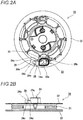
Fig. 2A] Fig. 2A is a side view showing a rope reel to which a rope is attached. - [
Fig. 2B] Fig. 2B is a front view showing the rope reel. - [
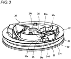
Fig. 3] Fig. 3 is a perspective view showing the rope reel to which the rope is attached. - [
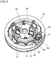
Fig. 4] Fig. 4 is a perspective view showing the rope reel. - [
Fig. 5] Fig. 5 is a perspective view of the rope reel as viewed from another angle. - [
Fig. 6] Fig. 6 is a perspective view showing a rope reel according to a first modification. - [
Fig. 7A] Fig. 7A is a perspective view showing a rope reel according to a second modification. - [
Fig. 7B] Fig. 7B is a partially enlarged perspective view showing the rope reel according to the second modification. - Embodiments of the present invention will be described with reference to the drawings.
- A
recoil starter 10 according to the present embodiment starts an engine by applying a rotational force to anengine crankshaft 42. As shown inFig. 1 , therecoil starter 10 includes astarter case 11, arope reel 20, aratchet member 40, adrive pulley 41, and the like. - The
starter case 11 is disposed so as to cover a side surface portion of the engine while accommodating main components of therecoil starter 10. At a center of thestarter case 11, areel support shaft 11a protruding inward so as to face theengine crankshaft 42 is provided. Therope reel 20 to be described later is rotatably attached to thereel support shaft 11a. - The
rope reel 20 is a wheel-shaped member, and includes arope holding groove 21 configured such that arope 30 is wound around therope reel 20. Thereel support shaft 11a passes through a hole formed in a central portion of therope reel 20, and thus therope reel 20 is rotatably attached to thereel support shaft 11a. One end of therope 30 wound around therope reel 20 is fixed to therope reel 20, and the other end of therope 30 is drawn out to an outside of thestarter case 11. Therefore, therope reel 20 is configured to rotate around thereel support shaft 11a by an operator vigorously pulling the drawn outrope 30. - When the operator releases the drawn out
rope 30, therope reel 20 is reversely rotated by a return spring, and therope 30 is automatically wound up. The return spring is a spiral spring, and one end of the return spring is fixed to thestarter case 11 and the other end is fixed to therope reel 20. When therope reel 20 rotates by pulling out therope 30, a rotational force is accumulated in the return spring. Further, when the pulledrope 30 is released, therope reel 20 is reversely rotated due to the spring force accumulated in the return spring, and therope reel 20 winds up therope 30. - The
ratchet member 40 is attached to therope reel 20 so as to rotate integrally with therope reel 20. Theratchet member 40 is swingably attached to a side surface of therope reel 20, and theratchet member 40 is formed so as to engage with an inner peripheral surface of adrive pulley 41 to be described later, by swinging theratchet member 40. Since a structure in the related art may be applied to theratchet member 40, although a configuration of theratchet member 40 is not described in detail, theratchet member 40 is configured to engage with thedrive pulley 41 only when therope reel 20 attempts to rotate in a predetermined direction (a direction in which the engine is started) with respect to thedrive pulley 41. - That is, when the
rope reel 20 is rotated by performing an operation of pulling out therope 30, theratchet member 40 swings to engage with thedrive pulley 41, and the rotational force of therope reel 20 is transmitted to thedrive pulley 41. Meanwhile, when therope reel 20 is rotating in a winding direction of therope 30 or when therope reel 20 is not rotating, theratchet member 40 swings in a retracting direction and does not engage with thedrive pulley 41. As a result, therope reel 20 and thedrive pulley 41 do not transmit rotational force to each other. - The
drive pulley 41 is a tubular member and is connected to theengine crankshaft 42. Thedrive pulley 41 is rotatably supported coaxially with the rotation shaft (reel support shaft 11a) of therope reel 20. When the rotational force of therope reel 20 is transmitted to the drivepulley 41 and thedrive pulley 41 starts to rotate, theengine crankshaft 42 integrally coupled to the drivepulley 41 rotates, and a starting rotational force is applied to the engine. - In addition to the drive
pulley 41, arotation member 43 that rotates integrally with theengine crankshaft 42 is attached to theengine crankshaft 42 according to the present embodiment. For example, arotation member 43 having a fan shape for blowing air to the engine is attached. - In the
recoil starter 10 described above, an end of therope 30 attached to therope reel 20 is locked to a side surface of therope reel 20 by forming aknot 30b. As shown inFig. 1 , theknot 30b of therope 30 is fixed to a side surface of therope reel 20 disposed on an engine side. According to the above configuration, there is no need to provide a gap for holding theknot 30b of therope 30 between thestarter case 11 covering therope reel 20 and therope reel 20, so that thestarter case 11 and therope reel 20 can be disposed as close as possible to each other. Therefore, a width of therecoil starter 10 can be reduced as much as possible. - However, as shown in
Fig. 1 , if a portion of therope 30 on the front end side with respect to theknot 30b is not fixed, afront end portion 30a of therope 30 may interfere with therotation member 43 on the engine side. In this regard, therope reel 20 according to the present embodiment can hold the end of therope 30, and is formed so as to prevent interference between therotation member 43 and thefront end portion 30a of therope 30. - That is, as shown in
Figs. 2A and 2B , therope reel 20 according to the present embodiment includesflange portions 22 disposed on both sides of therope holding groove 21, anend accommodating portion 23 provided on the side surface of therope reel 20, and anarch portion 24 provided on the side surface of therope reel 20 adjacent to theend accommodating portion 23. - The
flange portions 22 are formed in a pair so as to face each other, and therope holding groove 21 is formed between the pair offlange portions 22. As shown inFigs. 4 and5 , theflange portion 22 disposed on the engine side in the pair offlange portions 22 is provided with a throughhole 22a configured to allow an end of therope 30 wound around therope holding groove 21 to pass therethrough. - The
end accommodating portion 23 is configured to accommodate theknot 30b of therope 30, and is formed bywalls 23a surrounding a periphery of the throughhole 22a.
Theend accommodating portion 23 is surrounded by thewalls 23a provided so as to protrude from one side of therope reel 20 in an axial direction of therope reel 20. Further, since front end portions of thewalls 23a are not covered, as shown inFig. 2A , theknot 30b of therope 30 is exposed on the side surface of therope reel 20. - As shown in
Fig. 5 , aninsertion hole 23b is formed in thewall 23a of theend accommodating portion 23. Theinsertion hole 23b is formed in at least one of thewalls 23a forming theend accommodating portion 23. In the present embodiment, when viewed from the throughhole 22a, theinsertion hole 23b is formed in thewall 23a disposed in a peripheral direction. Theinsertion hole 23b establishes communication between theend accommodating portion 23 and thearch portion 24. In other words, theinsertion hole 23b is configured such that therope 30 is guided to thearch portion 24 by inserting therope 30 into theinsertion hole 23b from theend accommodating portion 23. - The
arch portion 24 is configured to hold a portion of therope 30 on the front end side with respect to theknot 30b. An annular insertion path through which therope 30 can be inserted is formed in thearch portion 24, and thearch portion 24 can hold theinterested rope 30 along the side surface of therope reel 20. Thearch portion 24 according to the present embodiment is formed continuously with theinsertion hole 23b formed in thewall 23a of theend accommodating portion 23. In other words, theend accommodating portion 23 is provided on one side and thearch portion 24 is provided on the other side across thewall 23a in which theinsertion hole 23b is formed. - The
arch portion 24 is disposed adjacent to theend accommodating portion 23 along a peripheral direction of theflange portion 22. Therefore, as shown inFig. 2A , the end of therope 30 held by thearch portion 24 is also held along the peripheral direction of theflange portion 22. - The
arch portion 24 according to the present embodiment includes a pair ofside walls 24c erected perpendicularly to the side surface of therope reel 20, and anupper wall 24a connecting upper end portions of the pair ofside walls 24c. More specifically, a substantially U-shapedarch portion 24 is formed by the pair ofside walls 24c and theupper wall 24a. A width of the arch portion 24 (a width of the pair ofside walls 24c and a width between the side surface of therope reel 20 and theupper wall 24a) is designed to be slightly larger than a diameter of therope 30 in order to facilitate insertion of thefront end portion 30a of therope 30. - For example, as shown in
Fig. 4 , theupper wall 24a is provided with anotch 24b at an end portion far from the throughhole 22a (or the end accommodating portion 23) (in other words, theupper wall 24a is provided with anotch 24b at a side where therope 30 is guided out from the arch portion 24). By providing thenotch 24b, when thefront end portion 30a of therope 30 passes through thearch portion 24, thefront end portion 30a is easily pulled out from thenotch 24b. - Further, for example, as shown in
Fig. 3 , anopening 24d for exposing therope 30 is formed in theside wall 24c. By providing theopening 24d, when thefront end portion 30a of therope 30 passes through thearch portion 24, therope 30 can be operated from theopening 24d, and therope 30 can easily passes through. - In the present embodiment, a
scale 25 on which a position of thefront end portion 30a of therope 30 passing through thearch portion 24 is confirmed is provided on the side surface of therope reel 20. Thescale 25 is formed on an extension line of the arch portion 24 (at a position away from the arch portion 24) along the peripheral direction of theflange portion 22 at a predetermined interval from thearch portion 24. Thescale 25 is displayed on a side surface of therope reel 20 by a method in the related art such as engraving, molding, printing, or the like. When therope 30 is attached to therope reel 20, for example, as shown inFig. 2A , a position of theknot 30b is adjusted such that thefront end portion 30a of therope 30 has a length that does not exceed thescale 25. By attaching therope 30 in this manner, thefront end portion 30a of therope 30 that is not held by thearch portion 24 can be prevented from becoming too long, and thus thefront end portion 30a of therope 30 can be prevented from interfering with a member on the engine side. - As described above, according to the present embodiment, in order to pass the end of the
rope 30 wound around therope holding groove 21, the throughhole 22a provided in theflange portion 22 and thearch portion 24 provided on the side surface of therope reel 20 adjacent to the throughhole 22a are provided, therope 30 can be inserted through thearch portion 24 and the insertedrope 30 can be held along the side surface of therope reel 20. Therefore, since thefront end portion 30a of therope 30 can be firmly fixed by being inserted into thearch portion 24, thefront end portion 30a of therope 30 does not interfere with therotation member 43 on the engine side. Further, since thefront end portion 30a of therope 30 is held along the side surface of therope reel 20, therope reel 20 can be disposed close to therotation member 43, and the degree of freedom in layout can be increased. For example, the width of therecoil starter 10 can be reduced and therecoil starter 10 can be reduced in size. Further, since therope 30 can be removed simply by pulling out therope 30 from thearch portion 24, therope 30 can be easily replaced. - Further, the
walls 23a are formed so as to surround the periphery of the throughhole 22a to form theend accommodating portion 23 for accommodating theknot 30b of therope 30, and thearch portion 24 is formed continuously with theinsertion hole 23b formed in thewall 23a of theend accommodating portion 23. According to such a configuration, since theknot 30b of therope 30 may be formed with reference to a height of thewall 23a of theend accommodating portion 23, therope 30 can be easily attached. Further, therope 30 is held by thearch portion 24 simply by inserting the end of therope 30 on the front end side with respect to theknot 30b into theinsertion hole 23b formed in thewall 23a of theend accommodating portion 23, therope 30 can be prevented from interfering with therotation member 43 on the engine side. - Further, the
opening 24d for exposing therope 30 is formed in the side surface of thearch portion 24. Therefore, since therope 30 can be operated from theopening 24d when therope 30 is inserted or removed, the work of attaching or detaching therope 30 can be easily performed. - Further, the side surface of the
rope reel 20 is provided with thescale 25 for checking the position of thefront end portion 30a of therope 30 passing through thearch portion 24. According to such a configuration, since the length of the end of therope 30 can be managed by thescale 25, therope 30 can be attached so as not to interfere with therotation member 43 on the engine side. - Further, since the
arch portion 24 is formed integrally with therope reel 20 and is not a separate component, an increase in cost due to providing a separate component can be avoided. - A shape of the
arch portion 24 is not limited to the shape described in the above embodiment, and various shapes can be considered. - For example, as shown in
Fig. 6 , a semi-cylindricalarch portion 24 may be formed. In the example shown inFig. 6 , theend accommodating portion 23 is omitted, and theend accommodating portion 23 may have a simple shape by omitting it. - As shown in
Figs. 7A and 7B , thearch portion 24 may be formed by a holdingmember 27 that is detachable with respect to the side surface of therope reel 20. For example, a lockingclaw 27a having a barb shape may be provided at a front end of the holdingmember 27, and anattachment hole 28 that can be engaged with the lockingclaw 27a may be provided in the side surface of therope reel 20. Then, the holdingmember 27 may be attached to the side surface of therope reel 20 by engaging the lockingclaw 27a with theattachment hole 28, and thearch portion 24 that is annularly closed may be formed on the side surface of therope reel 20 by attaching the holdingmember 27. - If the
arch portion 24 is formed by the detachable holdingmember 27 in this way, the end of therope 30 can be pressed later, and thus the assemblability is improved. Further, in such a configuration, since there is no need to consider the ease of insertion of therope 30 into thearch portion 24, the width of thearch portion 24 does not need to be larger than the diameter of therope 30. Therefore, the width of thearch portion 24 can be set so as to press therope 30, and a holding force of therope 30 can be increased. - The present application is based on
Japanese Patent Application No. 2019-008412 filed on January 22, 2019
Claims (6)
- A rope reel provided on a recoil starter, comprising:a rope holding groove configured such that a rope is wound around the rope holding groove;a flange portion disposed on both sides of the rope holding groove;a through hole provided in the flange portion and configured to allow an end of the rope wound around the rope holding groove to pass through; andan arch portion provided on a side surface of the rope reel and adjacent to the through hole, whereinthe arch portion is configured such that the rope is inserted in the arch portion, and the arch portion is capable of holding the inserted rope along the side surface of the rope reel.
- The rope reel according to claim 1, further comprising:an end accommodating portion configured to accommodate a knot of the rope, whereinthe end accommodating portion includes a wall formed to surround a periphery of the through hole, and the arch portion is formed adjacently to an insertion hole formed in the wall.
- The rope reel according to claim 1 or 2, wherein
the arch portion includes an opening that exposes the rope at the side surface of the rope reel. - The rope reel according to any one of claims 1 to 3, whereinthe rope is configured to pass through the arch portion, anda scale is provided on the side surface of the rope reel so as to confirm a position of a front end portion of the rope.
- The rope reel according to any one of claims 1 to 4, wherein
the arch portion is a detachable holding member provided on the side surface of the rope reel. - A recoil starter comprising:the rope reel according to any one of claims 1 to 5, whereinthe arch portion is disposed at an engine side.
Applications Claiming Priority (2)
| Application Number | Priority Date | Filing Date | Title |
|---|---|---|---|
| JP2019008412 | 2019-01-22 | ||
| PCT/JP2020/001995 WO2020153379A1 (en) | 2019-01-22 | 2020-01-21 | Recoil stator rope reel and recoil stator |
Publications (3)
| Publication Number | Publication Date |
|---|---|
| EP3901446A1 true EP3901446A1 (en) | 2021-10-27 |
| EP3901446A4 EP3901446A4 (en) | 2022-10-12 |
| EP3901446B1 EP3901446B1 (en) | 2024-07-10 |
Family
ID=71736181
Family Applications (1)
| Application Number | Title | Priority Date | Filing Date |
|---|---|---|---|
| EP20745294.7A Active EP3901446B1 (en) | 2019-01-22 | 2020-01-21 | Recoil stator rope reel and recoil stator |
Country Status (5)
| Country | Link |
|---|---|
| US (1) | US11566594B2 (en) |
| EP (1) | EP3901446B1 (en) |
| JP (1) | JP7040823B2 (en) |
| CN (1) | CN113330209A (en) |
| WO (1) | WO2020153379A1 (en) |
Family Cites Families (21)
| Publication number | Priority date | Publication date | Assignee | Title |
|---|---|---|---|---|
| US2348547A (en) * | 1941-01-09 | 1944-05-09 | B M Kissel | Starting device |
| US2848987A (en) * | 1955-05-11 | 1958-08-26 | Motor Wheel Corp | Rewind engine starter |
| US3134376A (en) * | 1961-05-08 | 1964-05-26 | Ohlsson & Rice Inc | Engine starter reel and method of making the same |
| JPS5755969Y2 (en) * | 1977-02-26 | 1982-12-02 | ||
| JPS53117840A (en) | 1977-03-23 | 1978-10-14 | Matsushita Electric Ind Co Ltd | Cooling instrument |
| JPS5448221U (en) * | 1977-09-10 | 1979-04-04 | ||
| JPS5848914B2 (en) | 1977-09-24 | 1983-10-31 | ヤマハ株式会社 | Pitch bend device for electronic musical instruments |
| JPS59153971A (en) * | 1983-02-22 | 1984-09-01 | Sanshin Ind Co Ltd | Recoil starter |
| JPH0232868Y2 (en) * | 1985-01-24 | 1990-09-05 | ||
| US4658775A (en) * | 1985-12-23 | 1987-04-21 | Eaton Stamping Company | Rope starter for engines |
| US4841929A (en) * | 1987-12-17 | 1989-06-27 | White Consolidated Industries, Inc. | Portable rotary power tool |
| US4940028A (en) * | 1989-02-08 | 1990-07-10 | White Consolidated Industries, Inc. | Recoil pull rope reel apparatus for internal combustion engines |
| US5676103A (en) * | 1995-05-09 | 1997-10-14 | Starting Industrial Co., Ltd | Recoil starter |
| KR100962156B1 (en) * | 2002-05-20 | 2010-06-10 | 스타팅 고교 가부시키가이샤 | Recoil starter |
| US6959680B2 (en) * | 2002-07-24 | 2005-11-01 | Starting Industrial Co., Ltd. | Recoil starter |
| JP4523469B2 (en) * | 2005-03-29 | 2010-08-11 | スターテング工業株式会社 | Recoil starter |
| US8291879B2 (en) * | 2008-12-03 | 2012-10-23 | Techtronic Outdoor Products Technology Limited | Recoil starter system |
| JP5101483B2 (en) * | 2008-12-26 | 2012-12-19 | スターテング工業株式会社 | Recoil starter |
| JP5833910B2 (en) | 2011-12-19 | 2015-12-16 | スターテング工業株式会社 | Recoil starter mechanism |
| JP5416261B2 (en) | 2012-08-22 | 2014-02-12 | スターテング工業株式会社 | Recoil starter |
| JP6812312B2 (en) | 2017-06-21 | 2021-01-13 | 三菱重工業株式会社 | Plant support evaluation system and plant support evaluation method |
-
2020
- 2020-01-21 WO PCT/JP2020/001995 patent/WO2020153379A1/en not_active Ceased
- 2020-01-21 US US17/424,863 patent/US11566594B2/en active Active
- 2020-01-21 CN CN202080010838.2A patent/CN113330209A/en active Pending
- 2020-01-21 JP JP2020568173A patent/JP7040823B2/en active Active
- 2020-01-21 EP EP20745294.7A patent/EP3901446B1/en active Active
Also Published As
| Publication number | Publication date |
|---|---|
| JP7040823B2 (en) | 2022-03-23 |
| EP3901446A4 (en) | 2022-10-12 |
| CN113330209A (en) | 2021-08-31 |
| US20220090570A1 (en) | 2022-03-24 |
| EP3901446B1 (en) | 2024-07-10 |
| US11566594B2 (en) | 2023-01-31 |
| JPWO2020153379A1 (en) | 2021-10-28 |
| WO2020153379A1 (en) | 2020-07-30 |
Similar Documents
| Publication | Publication Date | Title |
|---|---|---|
| EP1312798B1 (en) | Recoil starter | |
| US4936782A (en) | Flat cable for steering device of vehicle | |
| JP2012157176A (en) | Protector for wire harness | |
| EP3901446B1 (en) | Recoil stator rope reel and recoil stator | |
| EP3613642B1 (en) | Flat cable winding device and method of assembling same | |
| CN1982691A (en) | Recoil starter | |
| JP2001114476A (en) | Wire harness winding device | |
| CN211419192U (en) | Releasing mechanism structure box | |
| JP2022116849A (en) | Cable winding device and assembly method therefor | |
| JP2521628Y2 (en) | Structure of drive unit for cable type wind regulator | |
| TWI791715B (en) | Dual-bearing reel | |
| JP5137898B2 (en) | Lapping tool | |
| JP2003337230A (en) | Optical fiber storage device and optical fiber storage method | |
| JP7411532B2 (en) | drive device | |
| JPH08256414A (en) | Protector | |
| JP2000179262A (en) | Roll blind winding shaft | |
| JP3886187B2 (en) | Shaft support device | |
| JP2991792B2 (en) | Rotary retractor shaft pretensioner | |
| JP2500212Y2 (en) | Cord winding device | |
| JP2004045620A (en) | Optical fiber storage device and optical fiber storage box | |
| JP4281598B2 (en) | Optical fiber wiring apparatus and construction method thereof | |
| JP2000355192A (en) | Transferable character correction tool | |
| JPH07159626A (en) | Optical signal cable fixture | |
| JP2015104261A (en) | Cable winding device and method for assembling the same | |
| JP2009057132A (en) | Cable / cord winder |
Legal Events
| Date | Code | Title | Description |
|---|---|---|---|
| STAA | Information on the status of an ep patent application or granted ep patent |
Free format text: STATUS: THE INTERNATIONAL PUBLICATION HAS BEEN MADE |
|
| PUAI | Public reference made under article 153(3) epc to a published international application that has entered the european phase |
Free format text: ORIGINAL CODE: 0009012 |
|
| STAA | Information on the status of an ep patent application or granted ep patent |
Free format text: STATUS: REQUEST FOR EXAMINATION WAS MADE |
|
| 17P | Request for examination filed |
Effective date: 20210721 |
|
| AK | Designated contracting states |
Kind code of ref document: A1 Designated state(s): AL AT BE BG CH CY CZ DE DK EE ES FI FR GB GR HR HU IE IS IT LI LT LU LV MC MK MT NL NO PL PT RO RS SE SI SK SM TR |
|
| DAV | Request for validation of the european patent (deleted) | ||
| DAX | Request for extension of the european patent (deleted) | ||
| A4 | Supplementary search report drawn up and despatched |
Effective date: 20220913 |
|
| RIC1 | Information provided on ipc code assigned before grant |
Ipc: F02N 15/00 20060101ALI20220907BHEP Ipc: F02N 3/02 20060101AFI20220907BHEP |
|
| GRAP | Despatch of communication of intention to grant a patent |
Free format text: ORIGINAL CODE: EPIDOSNIGR1 |
|
| STAA | Information on the status of an ep patent application or granted ep patent |
Free format text: STATUS: GRANT OF PATENT IS INTENDED |
|
| INTG | Intention to grant announced |
Effective date: 20240130 |
|
| GRAS | Grant fee paid |
Free format text: ORIGINAL CODE: EPIDOSNIGR3 |
|
| GRAA | (expected) grant |
Free format text: ORIGINAL CODE: 0009210 |
|
| STAA | Information on the status of an ep patent application or granted ep patent |
Free format text: STATUS: THE PATENT HAS BEEN GRANTED |
|
| AK | Designated contracting states |
Kind code of ref document: B1 Designated state(s): AL AT BE BG CH CY CZ DE DK EE ES FI FR GB GR HR HU IE IS IT LI LT LU LV MC MK MT NL NO PL PT RO RS SE SI SK SM TR |
|
| REG | Reference to a national code |
Ref country code: CH Ref legal event code: EP |
|
| REG | Reference to a national code |
Ref country code: DE Ref legal event code: R096 Ref document number: 602020033764 Country of ref document: DE |
|
| REG | Reference to a national code |
Ref country code: SE Ref legal event code: TRGR |
|
| REG | Reference to a national code |
Ref country code: LT Ref legal event code: MG9D |
|
| REG | Reference to a national code |
Ref country code: NL Ref legal event code: MP Effective date: 20240710 |
|
| PG25 | Lapsed in a contracting state [announced via postgrant information from national office to epo] |
Ref country code: PT Free format text: LAPSE BECAUSE OF FAILURE TO SUBMIT A TRANSLATION OF THE DESCRIPTION OR TO PAY THE FEE WITHIN THE PRESCRIBED TIME-LIMIT Effective date: 20241111 |
|
| REG | Reference to a national code |
Ref country code: AT Ref legal event code: MK05 Ref document number: 1702225 Country of ref document: AT Kind code of ref document: T Effective date: 20240710 |
|
| PG25 | Lapsed in a contracting state [announced via postgrant information from national office to epo] |
Ref country code: NL Free format text: LAPSE BECAUSE OF FAILURE TO SUBMIT A TRANSLATION OF THE DESCRIPTION OR TO PAY THE FEE WITHIN THE PRESCRIBED TIME-LIMIT Effective date: 20240710 |
|
| PG25 | Lapsed in a contracting state [announced via postgrant information from national office to epo] |
Ref country code: PT Free format text: LAPSE BECAUSE OF FAILURE TO SUBMIT A TRANSLATION OF THE DESCRIPTION OR TO PAY THE FEE WITHIN THE PRESCRIBED TIME-LIMIT Effective date: 20241111 Ref country code: NL Free format text: LAPSE BECAUSE OF FAILURE TO SUBMIT A TRANSLATION OF THE DESCRIPTION OR TO PAY THE FEE WITHIN THE PRESCRIBED TIME-LIMIT Effective date: 20240710 |
|
| PG25 | Lapsed in a contracting state [announced via postgrant information from national office to epo] |
Ref country code: NO Free format text: LAPSE BECAUSE OF FAILURE TO SUBMIT A TRANSLATION OF THE DESCRIPTION OR TO PAY THE FEE WITHIN THE PRESCRIBED TIME-LIMIT Effective date: 20241010 |
|
| PG25 | Lapsed in a contracting state [announced via postgrant information from national office to epo] |
Ref country code: FI Free format text: LAPSE BECAUSE OF FAILURE TO SUBMIT A TRANSLATION OF THE DESCRIPTION OR TO PAY THE FEE WITHIN THE PRESCRIBED TIME-LIMIT Effective date: 20240710 Ref country code: PL Free format text: LAPSE BECAUSE OF FAILURE TO SUBMIT A TRANSLATION OF THE DESCRIPTION OR TO PAY THE FEE WITHIN THE PRESCRIBED TIME-LIMIT Effective date: 20240710 Ref country code: GR Free format text: LAPSE BECAUSE OF FAILURE TO SUBMIT A TRANSLATION OF THE DESCRIPTION OR TO PAY THE FEE WITHIN THE PRESCRIBED TIME-LIMIT Effective date: 20241011 |
|
| PG25 | Lapsed in a contracting state [announced via postgrant information from national office to epo] |
Ref country code: BG Free format text: LAPSE BECAUSE OF FAILURE TO SUBMIT A TRANSLATION OF THE DESCRIPTION OR TO PAY THE FEE WITHIN THE PRESCRIBED TIME-LIMIT Effective date: 20240710 |
|
| PG25 | Lapsed in a contracting state [announced via postgrant information from national office to epo] |
Ref country code: LV Free format text: LAPSE BECAUSE OF FAILURE TO SUBMIT A TRANSLATION OF THE DESCRIPTION OR TO PAY THE FEE WITHIN THE PRESCRIBED TIME-LIMIT Effective date: 20240710 |
|
| PG25 | Lapsed in a contracting state [announced via postgrant information from national office to epo] |
Ref country code: IS Free format text: LAPSE BECAUSE OF FAILURE TO SUBMIT A TRANSLATION OF THE DESCRIPTION OR TO PAY THE FEE WITHIN THE PRESCRIBED TIME-LIMIT Effective date: 20241110 Ref country code: AT Free format text: LAPSE BECAUSE OF FAILURE TO SUBMIT A TRANSLATION OF THE DESCRIPTION OR TO PAY THE FEE WITHIN THE PRESCRIBED TIME-LIMIT Effective date: 20240710 |
|
| PG25 | Lapsed in a contracting state [announced via postgrant information from national office to epo] |
Ref country code: HR Free format text: LAPSE BECAUSE OF FAILURE TO SUBMIT A TRANSLATION OF THE DESCRIPTION OR TO PAY THE FEE WITHIN THE PRESCRIBED TIME-LIMIT Effective date: 20240710 |
|
| PG25 | Lapsed in a contracting state [announced via postgrant information from national office to epo] |
Ref country code: ES Free format text: LAPSE BECAUSE OF FAILURE TO SUBMIT A TRANSLATION OF THE DESCRIPTION OR TO PAY THE FEE WITHIN THE PRESCRIBED TIME-LIMIT Effective date: 20240710 Ref country code: RS Free format text: LAPSE BECAUSE OF FAILURE TO SUBMIT A TRANSLATION OF THE DESCRIPTION OR TO PAY THE FEE WITHIN THE PRESCRIBED TIME-LIMIT Effective date: 20241010 |
|
| PG25 | Lapsed in a contracting state [announced via postgrant information from national office to epo] |
Ref country code: RS Free format text: LAPSE BECAUSE OF FAILURE TO SUBMIT A TRANSLATION OF THE DESCRIPTION OR TO PAY THE FEE WITHIN THE PRESCRIBED TIME-LIMIT Effective date: 20241010 Ref country code: PL Free format text: LAPSE BECAUSE OF FAILURE TO SUBMIT A TRANSLATION OF THE DESCRIPTION OR TO PAY THE FEE WITHIN THE PRESCRIBED TIME-LIMIT Effective date: 20240710 Ref country code: NO Free format text: LAPSE BECAUSE OF FAILURE TO SUBMIT A TRANSLATION OF THE DESCRIPTION OR TO PAY THE FEE WITHIN THE PRESCRIBED TIME-LIMIT Effective date: 20241010 Ref country code: LV Free format text: LAPSE BECAUSE OF FAILURE TO SUBMIT A TRANSLATION OF THE DESCRIPTION OR TO PAY THE FEE WITHIN THE PRESCRIBED TIME-LIMIT Effective date: 20240710 Ref country code: IS Free format text: LAPSE BECAUSE OF FAILURE TO SUBMIT A TRANSLATION OF THE DESCRIPTION OR TO PAY THE FEE WITHIN THE PRESCRIBED TIME-LIMIT Effective date: 20241110 Ref country code: HR Free format text: LAPSE BECAUSE OF FAILURE TO SUBMIT A TRANSLATION OF THE DESCRIPTION OR TO PAY THE FEE WITHIN THE PRESCRIBED TIME-LIMIT Effective date: 20240710 Ref country code: GR Free format text: LAPSE BECAUSE OF FAILURE TO SUBMIT A TRANSLATION OF THE DESCRIPTION OR TO PAY THE FEE WITHIN THE PRESCRIBED TIME-LIMIT Effective date: 20241011 Ref country code: FI Free format text: LAPSE BECAUSE OF FAILURE TO SUBMIT A TRANSLATION OF THE DESCRIPTION OR TO PAY THE FEE WITHIN THE PRESCRIBED TIME-LIMIT Effective date: 20240710 Ref country code: ES Free format text: LAPSE BECAUSE OF FAILURE TO SUBMIT A TRANSLATION OF THE DESCRIPTION OR TO PAY THE FEE WITHIN THE PRESCRIBED TIME-LIMIT Effective date: 20240710 Ref country code: BG Free format text: LAPSE BECAUSE OF FAILURE TO SUBMIT A TRANSLATION OF THE DESCRIPTION OR TO PAY THE FEE WITHIN THE PRESCRIBED TIME-LIMIT Effective date: 20240710 Ref country code: AT Free format text: LAPSE BECAUSE OF FAILURE TO SUBMIT A TRANSLATION OF THE DESCRIPTION OR TO PAY THE FEE WITHIN THE PRESCRIBED TIME-LIMIT Effective date: 20240710 |
|
| REG | Reference to a national code |
Ref country code: DE Ref legal event code: R097 Ref document number: 602020033764 Country of ref document: DE |
|
| PG25 | Lapsed in a contracting state [announced via postgrant information from national office to epo] |
Ref country code: RO Free format text: LAPSE BECAUSE OF FAILURE TO SUBMIT A TRANSLATION OF THE DESCRIPTION OR TO PAY THE FEE WITHIN THE PRESCRIBED TIME-LIMIT Effective date: 20240710 Ref country code: DK Free format text: LAPSE BECAUSE OF FAILURE TO SUBMIT A TRANSLATION OF THE DESCRIPTION OR TO PAY THE FEE WITHIN THE PRESCRIBED TIME-LIMIT Effective date: 20240710 Ref country code: SM Free format text: LAPSE BECAUSE OF FAILURE TO SUBMIT A TRANSLATION OF THE DESCRIPTION OR TO PAY THE FEE WITHIN THE PRESCRIBED TIME-LIMIT Effective date: 20240710 |
|
| PG25 | Lapsed in a contracting state [announced via postgrant information from national office to epo] |
Ref country code: EE Free format text: LAPSE BECAUSE OF FAILURE TO SUBMIT A TRANSLATION OF THE DESCRIPTION OR TO PAY THE FEE WITHIN THE PRESCRIBED TIME-LIMIT Effective date: 20240710 |
|
| PG25 | Lapsed in a contracting state [announced via postgrant information from national office to epo] |
Ref country code: CZ Free format text: LAPSE BECAUSE OF FAILURE TO SUBMIT A TRANSLATION OF THE DESCRIPTION OR TO PAY THE FEE WITHIN THE PRESCRIBED TIME-LIMIT Effective date: 20240710 |
|
| PG25 | Lapsed in a contracting state [announced via postgrant information from national office to epo] |
Ref country code: SK Free format text: LAPSE BECAUSE OF FAILURE TO SUBMIT A TRANSLATION OF THE DESCRIPTION OR TO PAY THE FEE WITHIN THE PRESCRIBED TIME-LIMIT Effective date: 20240710 |
|
| PLBE | No opposition filed within time limit |
Free format text: ORIGINAL CODE: 0009261 |
|
| STAA | Information on the status of an ep patent application or granted ep patent |
Free format text: STATUS: NO OPPOSITION FILED WITHIN TIME LIMIT |
|
| 26N | No opposition filed |
Effective date: 20250411 |
|
| REG | Reference to a national code |
Ref country code: CH Ref legal event code: PL |
|
| PG25 | Lapsed in a contracting state [announced via postgrant information from national office to epo] |
Ref country code: LU Free format text: LAPSE BECAUSE OF NON-PAYMENT OF DUE FEES Effective date: 20250121 Ref country code: MC Free format text: LAPSE BECAUSE OF FAILURE TO SUBMIT A TRANSLATION OF THE DESCRIPTION OR TO PAY THE FEE WITHIN THE PRESCRIBED TIME-LIMIT Effective date: 20240710 |
|
| GBPC | Gb: european patent ceased through non-payment of renewal fee |
Effective date: 20250121 |
|
| PG25 | Lapsed in a contracting state [announced via postgrant information from national office to epo] |
Ref country code: GB Free format text: LAPSE BECAUSE OF NON-PAYMENT OF DUE FEES Effective date: 20250121 Ref country code: BE Free format text: LAPSE BECAUSE OF NON-PAYMENT OF DUE FEES Effective date: 20250131 |
|
| PG25 | Lapsed in a contracting state [announced via postgrant information from national office to epo] |
Ref country code: FR Free format text: LAPSE BECAUSE OF NON-PAYMENT OF DUE FEES Effective date: 20250131 |
|
| PG25 | Lapsed in a contracting state [announced via postgrant information from national office to epo] |
Ref country code: CH Free format text: LAPSE BECAUSE OF NON-PAYMENT OF DUE FEES Effective date: 20250131 |
|
| REG | Reference to a national code |
Ref country code: BE Ref legal event code: MM Effective date: 20250131 |
|
| PGFP | Annual fee paid to national office [announced via postgrant information from national office to epo] |
Ref country code: SE Payment date: 20251210 Year of fee payment: 7 |
|
| PG25 | Lapsed in a contracting state [announced via postgrant information from national office to epo] |
Ref country code: IE Free format text: LAPSE BECAUSE OF NON-PAYMENT OF DUE FEES Effective date: 20250121 |
|
| PGFP | Annual fee paid to national office [announced via postgrant information from national office to epo] |
Ref country code: DE Payment date: 20251203 Year of fee payment: 7 |
|
| PGFP | Annual fee paid to national office [announced via postgrant information from national office to epo] |
Ref country code: IT Payment date: 20251219 Year of fee payment: 7 |