JP7411532B2 - drive device - Google Patents

drive device Download PDF

Info

Publication number
JP7411532B2
JP7411532B2 JP2020178945A JP2020178945A JP7411532B2 JP 7411532 B2 JP7411532 B2 JP 7411532B2 JP 2020178945 A JP2020178945 A JP 2020178945A JP 2020178945 A JP2020178945 A JP 2020178945A JP 7411532 B2 JP7411532 B2 JP 7411532B2
Authority
JP
Japan
Prior art keywords
cam
driven member
engaging
engaged
driven
Prior art date
Legal status (The legal status is an assumption and is not a legal conclusion. Google has not performed a legal analysis and makes no representation as to the accuracy of the status listed.)
Active
Application number
JP2020178945A
Other languages
Japanese (ja)
Other versions
JP2021071196A (en
Inventor
研一朗 妹尾
Current Assignee (The listed assignees may be inaccurate. Google has not performed a legal analysis and makes no representation or warranty as to the accuracy of the list.)
Nippon Cable System Inc
Hi Lex Corp
Original Assignee
Nippon Cable System Inc
Hi Lex Corp
Priority date (The priority date is an assumption and is not a legal conclusion. Google has not performed a legal analysis and makes no representation as to the accuracy of the date listed.)
Filing date
Publication date
Application filed by Nippon Cable System Inc, Hi Lex Corp filed Critical Nippon Cable System Inc
Publication of JP2021071196A publication Critical patent/JP2021071196A/en
Application granted granted Critical
Publication of JP7411532B2 publication Critical patent/JP7411532B2/en
Active legal-status Critical Current
Anticipated expiration legal-status Critical

Links

Images

Description

本発明は、駆動装置に関する。 The present invention relates to a drive device.

例えば車椅子の車両への固定装置など、所定の対象物を所定の位置に保持する機構が知られている(たとえば、特許文献1参照)。例えば車椅子を車両内において所定の位置に保持する場合、駆動部によってワイヤを駆動して、車椅子を車両内に牽引した後、車両の運転中などにおいて車椅子が移動しないようにワイヤを所定の位置に保持して、車椅子を安定して保持する必要がある。一方、車椅子など所定の対象物を所定の位置に保持するための固定装置は、駆動部によって回転する従動部材の回転を規制するための安価でシンプルな構造を有していることが望ましい。 For example, mechanisms for holding a predetermined object in a predetermined position, such as a device for fixing a wheelchair to a vehicle, are known (for example, see Patent Document 1). For example, when holding a wheelchair in a predetermined position in a vehicle, the drive unit drives the wire to tow the wheelchair into the vehicle, and then holds the wire in a predetermined position to prevent the wheelchair from moving while the vehicle is being driven. must be held to hold the wheelchair stable. On the other hand, it is desirable that a fixing device for holding a predetermined object such as a wheelchair in a predetermined position has an inexpensive and simple structure for regulating rotation of a driven member rotated by a drive section.

シンプルな構造で対象物を所定の位置に保持するものとして、特許文献2には、クラッチ機構を用いた装置が開示されている。この特許文献2の装置は、モータと、モータによって回転するカム軸と、カム軸の径方向外側に設けられ、カム軸に対して相対回転可能なカムケースと、カムケースの上に設けられ、そのスリーブがカムケースの径方向外側に位置するプーリ本体とを有している。カムケースは、カム軸を挟んで対称に設けられた一対のレバー状のカム本体を有している。カム本体はカムケースに対してピンによって揺動自在に取り付けられており、カム軸が所定量一方向に回転すると、カム本体のクラッチ凸部が径方向外側に突出して、プーリ本体のスリーブに設けられたクラッチ凹部と係合するように構成されている。このクラッチ結合により、カム軸の回転がプーリ本体に伝達され、プーリ本体に巻き付けられた開閉紐が操作され、モータの停止によって、駆動部の駆動に対して従動する従動部材であるプーリ本体の回転は停止して、プーリ本体による操作対象は所定の位置で停止する。モータが停止したとき、特許文献2では、カム本体は、カム本体を径方向内側に付勢する戻しばねにより、クラッチ凹部と係合しない状態に戻される。 Patent Document 2 discloses a device using a clutch mechanism that holds an object in a predetermined position with a simple structure. The device of Patent Document 2 includes a motor, a camshaft rotated by the motor, a cam case provided on the radially outer side of the camshaft and rotatable relative to the camshaft, and a sleeve provided on the cam case. has a pulley body located on the radially outer side of the cam case. The cam case has a pair of lever-shaped cam bodies arranged symmetrically across the cam shaft. The cam body is swingably attached to the cam case by a pin, and when the camshaft rotates in one direction by a predetermined amount, the clutch protrusion of the cam body protrudes radially outward and engages the clutch protrusion provided in the sleeve of the pulley body. The clutch recess is configured to engage with the clutch recess. Through this clutch engagement, the rotation of the camshaft is transmitted to the pulley body, the opening/closing string wrapped around the pulley body is operated, and when the motor is stopped, the pulley body, which is a driven member that follows the drive of the drive unit, rotates. stops, and the target operated by the pulley body stops at a predetermined position. When the motor stops, in Patent Document 2, the cam body is returned to a state out of engagement with the clutch recess by a return spring that biases the cam body radially inward.

特開2013-121415号公報Japanese Patent Application Publication No. 2013-121415 特開平5-231449号公報Japanese Patent Application Publication No. 5-231449

特許文献2のような構造の場合、カム本体(以下、係合部材という)が戻しばねによってクラッチ凹部(以下、被係合部という)と係合しない状態になるため、車椅子を固定するためのワイヤやベルトなどを所定の張力を保った状態を維持することができない。また、車椅子を固定するためのワイヤやベルトなどから張力が加わった場合、特許文献2の係合部材(カム本体)と被係合部(クラッチ凹部)との間の係合は解除されにくくなる。このような状態で、係合部材(カム本体)を駆動部の回転によって径方向内側へ収納する方向へ動作させようとしても、特許文献2では、駆動部によりカム部材(カム軸)が係合部材(カム本体)を径方向外側へ突出させる方向とは反対方向に回転したとしても、係合部材(カム本体)を径方向内側へ収納する方向へ力が加わらず、駆動部の回転力によって係合部材(カム本体)を径方向内側へ収納することができない。 In the case of the structure of Patent Document 2, the cam body (hereinafter referred to as the engaging member) is not engaged with the clutch recessed portion (hereinafter referred to as the engaged portion) due to the return spring, so it is difficult to fix the wheelchair. It is not possible to maintain a predetermined tension on wires, belts, etc. Furthermore, when tension is applied from wires or belts used to secure the wheelchair, the engagement between the engaging member (cam body) and the engaged portion (clutch recess) of Patent Document 2 becomes difficult to release. . In such a state, even if an attempt is made to move the engaging member (cam body) in the direction of retracting the engaging member (cam body) radially inward by rotation of the driving part, in Patent Document 2, the cam member (cam shaft) is not engaged by the driving part. Even if the member (cam body) is rotated in the opposite direction to the direction in which the member (cam body) protrudes radially outward, no force is applied in the direction to retract the engaging member (cam body) radially inward, and the rotational force of the drive unit The engaging member (cam body) cannot be stored radially inward.

そこで、本発明は、駆動部の駆動力によってカム部材を両方向に回転させることで、カム部材によって動作する係合部材を被係合部に対して係合状態と係合解除状態とすることが可能な、駆動装置の提供を目的とする。 Therefore, the present invention allows the engaging member operated by the cam member to be brought into an engaged state and a disengaged state with respect to the engaged part by rotating the cam member in both directions by the driving force of the driving part. The purpose is to provide a drive device that is possible.

本発明の駆動装置は、駆動部と、前記駆動部の駆動力により第一方向と、前記第一方向の反対方向となる第二方向に回転するカム部材と、前記カム部材の回転によって動作する係合部材を有し、前記カム部材に対して相対回転可能な第一従動部材と、前記係合部材が係合する被係合部を有し、前記カム部材と前記第一従動部材と相対回転可能な第二従動部材とを備え、前記係合部材は、前記被係合部に係合する爪部と、前記カム部材が前記第一方向または前記第二方向に回転したときに、前記カム部材に押圧される押圧部とを有し、前記押圧部は、前記カム部材が前記第一方向に回転したときに、前記カム部材に押圧されることによって、前記係合部材が前記第二従動部材と係合する係合状態となる第一押圧部と、前記カム部材が前記第二方向に回転したときに、前記カム部材に押圧されることによって、前記係合部材が前記第二従動部材との係合が解除される係合解除状態となる第二押圧部とを有し、前記カム部材は、前記係合部材の第一押圧部を押圧することにより前記係合部材を係合状態とさせる第一カム部と、前記係合部材の第二押圧部を押圧することにより前記係合解除状態とさせる第二カム部とを有している。 The drive device of the present invention includes a drive unit, a cam member that rotates in a first direction and a second direction opposite to the first direction by the driving force of the drive unit, and operates by rotation of the cam member. a first driven member that includes an engaging member and is rotatable relative to the cam member; and an engaged portion that is engaged with the engaging member, and that is rotatable relative to the cam member and the first driven member. a rotatable second driven member, and the engaging member includes a claw portion that engages with the engaged portion, and when the cam member rotates in the first direction or the second direction, the engaging member and a pressing part pressed by the cam member, and the pressing part is pressed by the cam member when the cam member rotates in the first direction, thereby causing the engaging member to move in the second direction. When the cam member is rotated in the second direction, the engaging member is pressed by the cam member, and the engaging member is brought into contact with the second driven member. a second pressing portion that is in a disengaged state in which engagement with the member is released, and the cam member engages the engaging member by pressing the first pressing portion of the engaging member. The engagement member has a first cam portion that brings the engagement member into the disengaged state, and a second cam portion that pushes the second pressing portion of the engagement member to bring the engagement member into the disengaged state.

本発明の駆動装置によれば、駆動部の駆動力によってカム部材を両方向に回転させることで、カム部材によって動作する係合部材を被係合部に対して係合状態と係合解除状態とすることができる。 According to the drive device of the present invention, by rotating the cam member in both directions by the driving force of the drive unit, the engaging member operated by the cam member can be brought into an engaged state and a disengaged state with respect to the engaged part. can do.

本発明の第1実施形態の駆動装置の分解斜視図である。FIG. 1 is an exploded perspective view of a drive device according to a first embodiment of the present invention. 本発明の第1実施形態の駆動装置を備えた、車椅子固定装置の斜視図である。FIG. 1 is a perspective view of a wheelchair fixing device including a drive device according to a first embodiment of the present invention. 本発明の第1実施形態の駆動装置を備えた、車椅子固定装置によって車椅子が固定された状態を示す概略図である。1 is a schematic diagram showing a state in which a wheelchair is fixed by a wheelchair fixing device including a drive device according to a first embodiment of the present invention; FIG. 本発明の第1実施形態の駆動装置を備えた、車椅子固定装置の上面図である。It is a top view of a wheelchair fixing device provided with the drive device of a 1st embodiment of the present invention. 図4のV-V線断面図である。5 is a sectional view taken along the line VV in FIG. 4. FIG. 図1の駆動装置のカム部材を示す斜視図である。FIG. 2 is a perspective view showing a cam member of the drive device of FIG. 1; 図1の駆動装置が動作する前の状態を示す概略図である。FIG. 2 is a schematic diagram showing a state before the drive device of FIG. 1 operates. 図1の駆動装置の係合部材が第二従動部材に係合した係合状態を示す概略図である。FIG. 2 is a schematic diagram showing an engaged state in which the engaging member of the drive device of FIG. 1 is engaged with a second driven member. 図1の駆動装置の係合部材と第二従動部材との係合が解除された係合解除状態を示す概略図である。FIG. 2 is a schematic diagram showing a disengaged state in which the engagement member and the second driven member of the drive device in FIG. 1 are disengaged. 係合部材の爪部と第二従動部材の被係合部との間の係合部分の拡大図である。FIG. 6 is an enlarged view of the engaging portion between the claw portion of the engaging member and the engaged portion of the second driven member. 係合状態にある係合部材の第二押圧部が、カム部材の第二カム部によって押圧された状態を示す概略図である。FIG. 6 is a schematic diagram showing a state in which the second pressing portion of the engaging member in the engaged state is pressed by the second cam portion of the cam member. 第2実施形態の駆動装置が動作する前の係合解除状態を示す概略図である。FIG. 7 is a schematic diagram showing a disengaged state before the drive device of the second embodiment operates. 第2実施形態の駆動装置の係合部材が第二従動部材に係合した係合状態を示す概略図である。FIG. 7 is a schematic diagram showing an engaged state in which the engaging member of the drive device of the second embodiment is engaged with the second driven member. 第2実施形態の駆動装置において、係合部材の爪部と第二従動部材の被係合部との間の係合部分の拡大図である。FIG. 7 is an enlarged view of the engaging portion between the claw portion of the engaging member and the engaged portion of the second driven member in the drive device of the second embodiment.

以下、図面を参照し、本発明の一実施形態の駆動装置を説明する。なお、以下に示す実施形態はあくまで一例であり、本発明の駆動装置は、以下の実施形態に限定されるものではない。 DESCRIPTION OF THE PREFERRED EMBODIMENTS A driving device according to an embodiment of the present invention will be described below with reference to the drawings. Note that the embodiment shown below is just an example, and the drive device of the present invention is not limited to the following embodiment.

<第1実施形態>
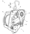
図1に示されるように、本実施形態の駆動装置1は、駆動部2と、駆動部2の駆動力により第一方向と、第一方向の反対方向となる第二方向に回転するカム部材3と、カム部材3の回転によって動作する係合部材41を有し、カム部材3に対して相対回転可能な第一従動部材4と、係合部材41が係合する被係合部51を有し、カム部材3と第一従動部材4と相対回転可能な第二従動部材5とを備えている。本実施形態では、カム部材3、第一従動部材4および第二従動部材5は、ハウジングHに収容されている(図5参照)。なお、本明細書において、カム部材3の一の回転方向を第一方向D1と呼び、第一方向D1の反対方向となる回転方向を第二方向D2と呼ぶ(図7~図9参照)。また、カム部材3が第一方向D1に回転するときの、第一従動部材4および第二従動部材5が回転する方向を同様に第一方向D1と呼び、第一従動部材4および第二従動部材5の、第一方向D1とは逆方向の回転方向を第二方向D2と呼ぶ。
<First embodiment>
As shown in FIG. 1, the drive device 1 of the present embodiment includes a drive unit 2 and a cam member that rotates in a first direction and a second direction opposite to the first direction by the drive force of the drive unit 2. 3, a first driven member 4 which has an engaging member 41 that operates by rotation of the cam member 3 and is rotatable relative to the cam member 3, and an engaged portion 51 that the engaging member 41 engages with. It includes a cam member 3, a first driven member 4, and a second driven member 5 that is relatively rotatable. In this embodiment, the cam member 3, the first driven member 4, and the second driven member 5 are housed in the housing H (see FIG. 5). In this specification, one rotational direction of the cam member 3 is referred to as a first direction D1, and a rotational direction opposite to the first direction D1 is referred to as a second direction D2 (see FIGS. 7 to 9). Further, when the cam member 3 rotates in the first direction D1, the direction in which the first driven member 4 and the second driven member 5 rotate is also called the first direction D1, and the direction in which the first driven member 4 and the second driven member 5 rotate. The rotation direction of the member 5 that is opposite to the first direction D1 is called a second direction D2.

駆動装置1は、駆動部2を駆動することによって、所定の操作対象OP(例えば図2および図3等参照)を操作する。より具体的には、駆動装置1は、駆動部2を駆動することによって、カム部材3、第一従動部材4および第二従動部材5を介して操作対象OPを操作する。なお、駆動装置1が適用される用途は、駆動部2の駆動によって、操作対象OPを操作することができれば、特に限定されない。駆動装置1によって操作される操作対象OPは、第二従動部材5に直接または間接的に接続され、第二従動部材5の回転によって所定の動作を行う。操作対象OPは、ベルトやワイヤ等の長尺部材(以下、長尺部材OPとも呼ぶ)とすることができるが、駆動装置1の動作によって操作可能なものであれば、特に限定されない。 The drive device 1 operates a predetermined operation target OP (see, for example, FIGS. 2 and 3) by driving the drive unit 2. More specifically, the drive device 1 operates the operation target OP via the cam member 3, the first driven member 4, and the second driven member 5 by driving the drive unit 2. Note that the application to which the drive device 1 is applied is not particularly limited as long as the operation target OP can be operated by driving the drive unit 2. The operation target OP operated by the drive device 1 is directly or indirectly connected to the second driven member 5, and performs a predetermined operation by rotation of the second driven member 5. The operation target OP can be an elongated member such as a belt or a wire (hereinafter also referred to as elongated member OP), but is not particularly limited as long as it can be operated by the operation of the drive device 1.

本実施形態では、駆動装置1は、図2に示されるように、長尺部材OPが巻き取りおよび繰り出される巻取部6を備え、第二従動部材5の第一方向D1および第二方向D2への回転(図7~図9参照)によって、長尺部材OPが巻き取りおよび繰り出されるように構成されている。本実施形態では、駆動装置1は、長尺部材OPの一端を固定対象(本実施形態では、図3に示される車椅子WC)に係合して、長尺部材OPを巻き取ることにより固定対象を固定するように構成されている。より具体的には、駆動装置1は、図3に示されるように、固定対象である車椅子WCを車両に固定するために、車椅子WCのフレームに取り付けられる長尺部材OPと、駆動装置1とを備えた車椅子固定装置Dに適用されている。本実施形態では、車椅子固定装置Dは、車両の車室内に複数設けられた駆動装置1を駆動することによって、長尺部材OPが巻き取られ、複数の方向から車椅子WCを牽引することで、車椅子WCを車両内で安定して保持する。本実施形態では、長尺部材OPは、図2および図3に示されるように、巻取部6に巻き取られるベルトOP1と、ベルトOP1の先端に設けられたフックOP2とを有している。しかし、長尺部材OPのベルトOP1に代えて、ワイヤなど他の長尺の部材が用いられていてもよい。また、長尺部材OPの先端に設けられたフックOP2に代えて、ワイヤの先端がループ状に形成されたものなど、他の係止部や固定部が設けられていてもよい。 In this embodiment, as shown in FIG. 2, the drive device 1 includes a winding section 6 where the elongated member OP is wound up and unwound, and the second driven member 5 is moved in the first direction D1 and the second direction D2. The elongated member OP is wound up and unwound by the rotation (see FIGS. 7 to 9). In the present embodiment, the drive device 1 engages one end of the elongated member OP with the fixed object (in this embodiment, the wheelchair WC shown in FIG. 3), and winds up the elongated member OP. is configured to be fixed. More specifically, as shown in FIG. 3, the drive device 1 includes an elongated member OP attached to the frame of the wheelchair WC, and the drive device 1 in order to fix the wheelchair WC, which is the fixation target, to the vehicle. It is applied to a wheelchair fixing device D equipped with. In the present embodiment, the wheelchair fixing device D is configured such that the elongated member OP is wound up by driving a plurality of drive devices 1 provided in the cabin of the vehicle, and the wheelchair WC is pulled from a plurality of directions. To stably hold a wheelchair WC in a vehicle. In this embodiment, the elongated member OP includes a belt OP1 that is wound around the winding section 6 and a hook OP2 provided at the tip of the belt OP1, as shown in FIGS. 2 and 3. . However, instead of the belt OP1 of the elongated member OP, another elongated member such as a wire may be used. Further, instead of the hook OP2 provided at the tip of the elongated member OP, other locking portions or fixing portions such as a wire having a loop-shaped tip may be provided.

巻取部6は、第二従動部材5が所定の方向に回転したときに、長尺部材OPが巻き取られるように、第二従動部材5に直接または間接的に接続されている。本実施形態では、第二従動部材5が第一方向D1に回転したときに、巻取部6は長尺部材OPを巻き取り、巻取部6から長尺部材OPが繰り出されたときに、第二従動部材5が第二方向D2に回転する。また、本実施形態では、巻取部6は、歯車等の伝動部材7(図1参照)を介して間接的に第二従動部材5に接続されている。巻取部6は、本実施形態では、長尺部材OPを巻き取る方向に回転するように、図示しないバネ部材によって付勢されている。 The winding section 6 is directly or indirectly connected to the second driven member 5 so that the elongated member OP is wound up when the second driven member 5 rotates in a predetermined direction. In this embodiment, when the second driven member 5 rotates in the first direction D1, the winding section 6 winds up the elongated member OP, and when the elongated member OP is unwound from the winding section 6, The second driven member 5 rotates in the second direction D2. Moreover, in this embodiment, the winding part 6 is indirectly connected to the second driven member 5 via a transmission member 7 (see FIG. 1) such as a gear. In this embodiment, the winding section 6 is biased by a spring member (not shown) so as to rotate in the direction of winding up the elongated member OP.

駆動部2は、カム部材3を回転させる駆動力を発生させる。駆動部2は、直接または間接的にカム部材3に接続されている。駆動部2の構造はカム部材3を回転させることができれば、特に限定されない。本実施形態では、駆動部2は、図1に示されるように、正逆回転可能なモータ21と、減速機構等を介してモータ21に接続され、カム部材3に接続される出力軸22とを備えている。 The drive unit 2 generates a driving force that rotates the cam member 3. The drive unit 2 is directly or indirectly connected to the cam member 3. The structure of the drive section 2 is not particularly limited as long as it can rotate the cam member 3. In this embodiment, as shown in FIG. 1, the drive unit 2 includes a motor 21 that can rotate in forward and reverse directions, and an output shaft 22 that is connected to the motor 21 via a speed reduction mechanism or the like and connected to the cam member 3. It is equipped with

カム部材3は、駆動部2の駆動力によって所定の軸X(図1、図5等参照)周りに回転する。本実施形態では、カム部材3は、駆動部2の回転方向に応じて、軸X周りに第一方向D1および第二方向D2に回転するように、駆動部2に直接または間接的に接続されている。カム部材3は、軸X周りに回転することによって、後述するように、第一従動部材4の係合部材41を、第二従動部材5と係合する係合状態(図8参照)および第二従動部材5との係合が解除される係合解除状態との間で動作させる(図9参照)。また、カム部材3は、後述するように、係合部材41が係合状態にあるときに第一方向D1に回転することによって、第一従動部材4を第一方向D1に回転させる。 The cam member 3 rotates around a predetermined axis X (see FIGS. 1, 5, etc.) by the driving force of the drive unit 2. In this embodiment, the cam member 3 is directly or indirectly connected to the drive unit 2 so as to rotate in the first direction D1 and the second direction D2 around the axis X depending on the rotation direction of the drive unit 2. ing. By rotating around the axis The second driven member 5 is operated between a disengaged state in which the engagement with the driven member 5 is disengaged (see FIG. 9). Further, as will be described later, the cam member 3 rotates in the first direction D1 when the engagement member 41 is in the engaged state, thereby rotating the first driven member 4 in the first direction D1.

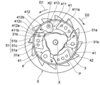
カム部材3は、図5および図6に示されるように、係合部材41の後述する第一押圧部411aを押圧することにより係合部材41を係合状態とさせる第一カム部31aと、係合部材41の後述する第二押圧部411bを押圧することにより係合解除状態とさせる第二カム部31bとを有している。カム部材3の形状および構造は、係合部材41を係合状態および係合解除状態との間で動作させることができれば特に限定されない。本実施形態では、カム部材3は、図1および図6に示されるように、駆動部2の出力軸22と接続される接続部32と、第一カム部31aおよび第二カム部31bを有するカム部31と、第二従動部材5の端面に軸支される軸部33とを有している。本実施形態では、接続部32、カム部31および軸部33は、軸X方向に沿って連続して設けられている。 As shown in FIGS. 5 and 6, the cam member 3 includes a first cam portion 31a that brings the engaging member 41 into an engaged state by pressing a first pressing portion 411a, which will be described later, of the engaging member 41. The engagement member 41 has a second cam portion 31b which is brought into the disengaged state by pressing a second pressing portion 411b (described later) of the engagement member 41. The shape and structure of the cam member 3 are not particularly limited as long as the engagement member 41 can be operated between an engaged state and a disengaged state. In this embodiment, the cam member 3 has a connecting part 32 connected to the output shaft 22 of the drive part 2, a first cam part 31a, and a second cam part 31b, as shown in FIGS. 1 and 6. It has a cam portion 31 and a shaft portion 33 that is pivotally supported by the end surface of the second driven member 5. In this embodiment, the connecting portion 32, the cam portion 31, and the shaft portion 33 are provided continuously along the axis X direction.

本実施形態では、図1および図6に示されるように、接続部32は筒状に形成され、筒状の接続部32の内面に、出力軸22の外周に設けられたスプラインとスプライン嵌合する嵌合部32a(図1参照)を有している。接続部32は、後述する第一従動部材4の第一基部42aに形成された貫通孔に挿通され、第一基部42aを軸X周りに回転できるように支持している。 In this embodiment, as shown in FIGS. 1 and 6, the connecting portion 32 is formed in a cylindrical shape, and the inner surface of the cylindrical connecting portion 32 is fitted with a spline provided on the outer periphery of the output shaft 22. It has a fitting part 32a (see FIG. 1). The connecting portion 32 is inserted into a through hole formed in a first base portion 42a of a first driven member 4, which will be described later, and supports the first base portion 42a so as to be rotatable around the axis X.

カム部31は、第一カム部31aおよび第二カム部31bを有する部位である。本実施形態では、図6に示されるように、カム部31は筒状体31cを有し、筒状体31cの外周に、当該筒状体31cの径方向外側に突出する複数(本実施形態では3つ)の山状のカムCを有している。カムCは、係合部材41に対応して設けられ、カム部材3の軸X方向の所定の位置に周回り方向に複数設けられている。なお、カム部31の形状や構造は、後述する第一カム部31aおよび第二カム部31bを有していれば、特に限定されない。本実施形態では、1つの山状のカムCに、第一カム部31aおよび第二カム部31bを有しているが、第一カム部31aおよび第二カム部31bは同一のカムCに設けられている必要はない。また、本実施形態では、カム部材3は、3つのカムC(3つの第一カム部31aおよび3つの第二カム部31b)を有しているが、カム部材3に設けられるカムCの数は特に限定されない。なお、筒状体31cは、後述する第一従動部材4の第二基部42bに形成された貫通孔に挿通され、第二基部42bを軸X周りに回転できるように支持している。カム部材3と係合部材41とは、カム部材3が軸X周り方向の一方に回転することにより、特定のカムCの第一カム部31aが1の係合部材41の第一押圧部411aを押圧し、カム部材3が軸X周り方向の他方に回転することにより、その特定のカムCの第二カム部31bが1の係合部材41に隣接して設けられた他の係合部材41の第二押圧部411bを押圧するように構成されている。 The cam portion 31 is a portion having a first cam portion 31a and a second cam portion 31b. In this embodiment, as shown in FIG. 6, the cam portion 31 has a cylindrical body 31c, and a plurality of cylindrical bodies (in this embodiment It has three mountain-shaped cams C. The cams C are provided corresponding to the engagement members 41, and a plurality of cams C are provided at predetermined positions in the axis X direction of the cam member 3 in the circumferential direction. Note that the shape and structure of the cam portion 31 are not particularly limited as long as it has a first cam portion 31a and a second cam portion 31b, which will be described later. In this embodiment, one mountain-shaped cam C has a first cam part 31a and a second cam part 31b, but the first cam part 31a and the second cam part 31b are provided in the same cam C. It doesn't have to be. Further, in this embodiment, the cam member 3 has three cams C (three first cam parts 31a and three second cam parts 31b), but the number of cams C provided in the cam member 3 is is not particularly limited. The cylindrical body 31c is inserted into a through hole formed in a second base 42b of the first driven member 4, which will be described later, and supports the second base 42b so as to be rotatable around the axis X. The cam member 3 and the engagement member 41 are such that when the cam member 3 rotates in one direction around the axis , and the cam member 3 rotates in the other direction around the axis 41, the second pressing portion 411b is pressed.

軸部33は、後述する第二従動部材5の端面に形成された孔に挿通されて、カム部材3を軸X周りに安定して回転するように支持している。 The shaft portion 33 is inserted into a hole formed in an end surface of a second driven member 5, which will be described later, and supports the cam member 3 so as to stably rotate around the axis X.

第一カム部31aは、後述するように、カム部材3が所定の方向(本実施形態では、第一方向D1)に回転したときに、第一従動部材4の係合部材41の第一押圧部411aを押圧する。これにより、係合部材41を第二従動部材5に係合する方向に移動させ、係合部材41を係合状態とする。第一カム部31aは、本実施形態では、カム部材3のカムCのうち、カム部材3の回転方向で一方側(第一方向D1側)の面に設けられている。本実施形態では、第一カム部31aは、係合部材41が係合状態および係合解除状態の両方の状態において、第一押圧部411aを第一方向D1に押圧できるように設けられている。 As will be described later, the first cam portion 31a is configured to press the engaging member 41 of the first driven member 4 when the cam member 3 rotates in a predetermined direction (first direction D1 in this embodiment). Press the portion 411a. Thereby, the engaging member 41 is moved in the direction of engaging with the second driven member 5, and the engaging member 41 is brought into the engaged state. In this embodiment, the first cam portion 31a is provided on a surface of the cam C of the cam member 3 on one side (first direction D1 side) in the rotational direction of the cam member 3. In this embodiment, the first cam portion 31a is provided so that the first pressing portion 411a can be pressed in the first direction D1 when the engagement member 41 is in both the engaged state and the disengaged state. .

本実施形態では、第一カム部31aは、カムCのうち、回転方向で一方側に形成され、周方向に湾曲した湾曲面である。しかし、第一カム部31aの形状は、第一押圧部411aを押圧することにより、係合部材41を係合状態とすることができれば特に限定されず、平面状であってもよい。また、本実施形態では、第一カム部31aは、1つのカム部材3において、カム部材3の周方向に離間して複数(3つ)設けられているが、第一カム部31aの数は特に限定されない。 In this embodiment, the first cam portion 31a is a curved surface formed on one side of the cam C in the rotational direction and curved in the circumferential direction. However, the shape of the first cam part 31a is not particularly limited as long as it can bring the engaging member 41 into the engaged state by pressing the first pressing part 411a, and may be flat. Further, in the present embodiment, a plurality (three) of the first cam portions 31a are provided in one cam member 3, spaced apart in the circumferential direction of the cam member 3, but the number of the first cam portions 31a is Not particularly limited.

第二カム部31bは、後述するように、カム部材3が所定の方向(本実施形態では、第二方向D2)に回転したときに、第一従動部材4の係合部材41の第二押圧部411bを押圧する。これにより、係合部材41を第二従動部材5との係合が解除される方向に移動させ、係合部材41を係合解除状態とする。第二カム部31bは、本実施形態では、カム部材3のカムCのうち、カム部材3の回転方向で他方側(第二方向D2側)の面に設けられている。 As will be described later, the second cam portion 31b provides a second pressing force of the engagement member 41 of the first driven member 4 when the cam member 3 rotates in a predetermined direction (in the present embodiment, the second direction D2). Press the portion 411b. Thereby, the engagement member 41 is moved in the direction in which the engagement with the second driven member 5 is released, and the engagement member 41 is brought into the disengaged state. In this embodiment, the second cam portion 31b is provided on the surface of the cam C of the cam member 3 on the other side (second direction D2 side) in the rotational direction of the cam member 3.

本実施形態では、第二カム部31bは、カムCのうち、回転方向で他方側に形成され、周方向に湾曲した湾曲面である。しかし、第二カム部31bの形状は、第二押圧部411bを押圧することにより、係合部材41を係合解除状態とすることができれば特に限定されず、平面状であってもよい。また、本実施形態では、第二カム部31bは、1つのカム部材3において、カム部材3の周方向に離間して複数(3つ)設けられているが、第二カム部31bの数は特に限定されない。また、本実施形態では、第一カム部31aおよび第二カム部31bは、同じ1つのカムCに連続した面として設けられているが、第一カム部31aおよび第二カム部31bのそれぞれは、互いに独立した別々の突出部として設けられていてもよい。 In this embodiment, the second cam portion 31b is a curved surface formed on the other side of the cam C in the rotational direction and curved in the circumferential direction. However, the shape of the second cam portion 31b is not particularly limited as long as it can bring the engagement member 41 into the disengaged state by pressing the second pressing portion 411b, and may be flat. Further, in the present embodiment, a plurality (three) of the second cam portions 31b are provided in one cam member 3, spaced apart in the circumferential direction of the cam member 3, but the number of the second cam portions 31b is Not particularly limited. Further, in this embodiment, the first cam part 31a and the second cam part 31b are provided as continuous surfaces on the same one cam C, but each of the first cam part 31a and the second cam part 31b is , may be provided as separate protrusions independent of each other.

第一従動部材4は、カム部材3に対して軸X周りに相対回転可能であるとともに、係合部材41を介してカム部材3の回転動作に従動して回転する。具体的には、カム部材3が第一方向D1に回転したとき、第一従動部材4の第一押圧部411aにカム部材3の第一カム部31aが当接するまでは、カム部材3が第一従動部材4に対して第一方向D1に回転する。第一従動部材4の第一押圧部411aにカム部材3の第一カム部31aが当接し、係合部材41を係合状態まで移動させた後、カム部材3が第一方向D1にさらに回転すると、第一従動部材4はカム部材3に従動して第一方向D1に回転する。また、カム部材3が第二方向D2に回転したとき、第一従動部材4は、第一従動部材4の第二押圧部411bにカム部材3の第二カム部31bが当接するまでは、カム部材3が第一従動部材4に対して第二方向D2に回転する。第一従動部材4の第二押圧部411bにカム部材3の第二カム部31bが当接し、係合部材41を係合解除状態まで移動させた後、カム部材3が第二方向D2に回転すると、第一従動部材4はカム部材3に従動して第二方向D2に回転する。 The first driven member 4 is rotatable relative to the cam member 3 around the axis X, and rotates following the rotational movement of the cam member 3 via the engagement member 41. Specifically, when the cam member 3 rotates in the first direction D1, the cam member 3 remains in the first position until the first cam portion 31a of the cam member 3 contacts the first pressing portion 411a of the first driven member 4. It rotates in the first direction D1 with respect to one driven member 4. After the first cam portion 31a of the cam member 3 contacts the first pressing portion 411a of the first driven member 4 and moves the engaging member 41 to the engaged state, the cam member 3 further rotates in the first direction D1. Then, the first driven member 4 is driven by the cam member 3 and rotates in the first direction D1. Further, when the cam member 3 rotates in the second direction D2, the first driven member 4 is rotated until the second cam portion 31b of the cam member 3 comes into contact with the second pressing portion 411b of the first driven member 4. The member 3 rotates in the second direction D2 relative to the first driven member 4. After the second cam portion 31b of the cam member 3 contacts the second pressing portion 411b of the first driven member 4 and moves the engagement member 41 to the disengaged state, the cam member 3 rotates in the second direction D2. Then, the first driven member 4 is driven by the cam member 3 and rotates in the second direction D2.

また、第一従動部材4は、係合部材41を介して第二従動部材5に係合して、第一従動部材4が第一方向D1に回転した際に、第二従動部材5を第一従動部材4の回転動作に従動させて第一方向D1に回転させる。 Further, the first driven member 4 engages with the second driven member 5 via the engagement member 41, and when the first driven member 4 rotates in the first direction D1, the second driven member 5 is moved to the second driven member 5. The first driven member 4 is rotated in the first direction D1 by following the rotational movement of the driven member 4.

第一従動部材4の形状および構造は、カム部材3に対して相対回転可能であるとともに、係合部材41を介してカム部材3の回転動作に従動し、係合部材41を介して第二従動部材5を回転させることができれば、特に限定されない。本実施形態では、第一従動部材4は、図1に示されるように、係合部材41と、係合部材41が設けられる基部42とを有している。 The shape and structure of the first driven member 4 are such that it is rotatable relative to the cam member 3, and is driven by the rotational movement of the cam member 3 via the engagement member 41, and the second There is no particular limitation as long as the driven member 5 can be rotated. In this embodiment, the first driven member 4 has an engaging member 41 and a base 42 on which the engaging member 41 is provided, as shown in FIG. 1 .

基部42は、係合部材41が設けられる部材である。基部42は、カム部材3および第二従動部材5に対して相対回転可能となるように、ハウジングH内で軸X周りに回転可能に支持されている。また、上述したように、第一従動部材4がカム部材3に従動して回転する場合、基部42および係合部材41がカム部材3に従動して軸X周りに回転する。基部42の形状および構造は特に限定されないが、本実施形態では、図1に示されるように、基部42は、一対の環状の板状体によって構成された第一基部42aおよび第二基部42bを備えている。第一基部42aおよび第二基部42bは、軸X方向で係合部材41を挟み込むように設けられている。第一基部42aおよび第二基部42bは、係合部材41の後述する軸部413を軸支する軸支部BRと、係合部材41を回転可能な状態で挟み込めるように、スペーサとして設けられ、互いに向かって突出した突出部Pを有している。突出部Pは、第一基部42aおよび第二基部42bの周縁領域において、周方向に互いに離間して設けられている。互いに離間した突出部Pの間の空間には、係合部材41が軸支部BRによって回転可能に設けられている。第一基部42aおよび第二基部42bは、係合部材41を軸X方向に挟み込んだ状態で、突出部Pの部分で互いに対して固定される。また、本実施形態では、カム部材3が第一基部42aおよび第二基部42bの貫通孔に挿通され、第一基部42aおよび第二基部42bのそれぞれは、カム部材3の筒状の接続部32およびカム部31の筒状体31cの外周面によって軸X周りに回転可能に支持されている。 The base portion 42 is a member on which the engagement member 41 is provided. The base portion 42 is rotatably supported within the housing H around the axis X so as to be rotatable relative to the cam member 3 and the second driven member 5. Further, as described above, when the first driven member 4 rotates following the cam member 3, the base portion 42 and the engagement member 41 rotate around the axis X following the cam member 3. Although the shape and structure of the base 42 are not particularly limited, in this embodiment, as shown in FIG. We are prepared. The first base portion 42a and the second base portion 42b are provided so as to sandwich the engagement member 41 in the axis X direction. The first base 42a and the second base 42b are provided as spacers so that the engagement member 41 can be rotatably sandwiched between the shaft support BR that pivotally supports a shaft 413 (described later) of the engagement member 41, They have protrusions P that protrude toward each other. The protrusions P are spaced apart from each other in the circumferential direction in the peripheral areas of the first base 42a and the second base 42b. In the space between the protrusions P spaced apart from each other, an engaging member 41 is rotatably provided by the shaft support BR. The first base portion 42a and the second base portion 42b are fixed to each other at the protruding portion P with the engaging member 41 sandwiched therebetween in the axis X direction. Further, in this embodiment, the cam member 3 is inserted into the through holes of the first base 42a and the second base 42b, and each of the first base 42a and the second base 42b is connected to the cylindrical connecting portion 32 of the cam member 3. The cam portion 31 is rotatably supported around the axis X by the outer circumferential surface of the cylindrical body 31c of the cam portion 31.

係合部材41は、カム部材3に押圧されることによって、第二従動部材5と係合する係合状態(図8参照)と第二従動部材5との係合が解除される係合解除状態(図9参照)との間で動作する。係合部材41は、図5に示されるように、被係合部51に係合する爪部412と、カム部材3が第一方向D1または第二方向D2に回転したときに、カム部材3に押圧される押圧部411とを有している。押圧部411は、カム部材3が第一方向D1に回転したときに、カム部材3に押圧されることによって、係合部材41が第二従動部材5と係合する係合状態(図8参照)となる第一押圧部411aと、カム部材3が第二方向D2に回転したときに、カム部材3に押圧されることによって、係合部材41が第二従動部材5との係合が解除される係合解除状態(図11の二点鎖線参照)となる第二押圧部411bとを有している。爪部412は、第一方向D1側で、後述する第二従動部材5の被係合部51と対向する第一係合部412aと、第二方向D2側で被係合部51と対向する第二係合部412bとを有している。第一係合部412aは、係合状態において、後述する被係合部51の短辺部51aと係合する。また、第二係合部412bは、後述する被係合部51の長辺部51bと対向する。本実施形態では、第二係合部412bは、長辺部51bと当接するように構成されている。なお、第二係合部412bは、係合状態において、長辺部51bの全体と当接せずに、長辺部51bとの間にクリアランスを有していてもよい。 When the engaging member 41 is pressed by the cam member 3, the engaging state is engaged with the second driven member 5 (see FIG. 8), and the disengaged state is where the engagement with the second driven member 5 is released. (see FIG. 9). As shown in FIG. 5, the engaging member 41 has a claw portion 412 that engages with the engaged portion 51, and when the cam member 3 rotates in the first direction D1 or the second direction D2, the cam member 3 It has a pressing part 411 that is pressed by. The pressing portion 411 is pressed by the cam member 3 when the cam member 3 rotates in the first direction D1, and thereby enters an engaged state in which the engaging member 41 engages with the second driven member 5 (see FIG. 8). ) When the first pressing portion 411a and the cam member 3 rotate in the second direction D2, the engagement member 41 is released from engagement with the second driven member 5 by being pressed by the cam member 3. The second pressing portion 411b is in the disengaged state (see the two-dot chain line in FIG. 11). The claw portion 412 has a first engaging portion 412a that faces an engaged portion 51 of a second driven member 5, which will be described later, on the first direction D1 side, and a first engaging portion 412a that faces the engaged portion 51 on the second direction D2 side. It has a second engaging portion 412b. In the engaged state, the first engaging portion 412a engages with a short side portion 51a of an engaged portion 51, which will be described later. Further, the second engaging portion 412b faces a long side portion 51b of the engaged portion 51, which will be described later. In this embodiment, the second engaging portion 412b is configured to abut against the long side portion 51b. In addition, the second engaging part 412b may have a clearance between the long side part 51b and the long side part 51b without contacting the entire long side part 51b in the engaged state.

係合部材41の動作の形態は、カム部材3に押圧されることによって、係合状態と係合解除状態との間で動作することができれば、特に限定されない。本実施形態では、係合部材41は、第一従動部材4において、軸Xに平行な第二の軸X2(図5参照)周りに回転するように設けられている。より具体的には、第一従動部材4は、係合部材41を回転可能に軸支する軸部413を有し、係合部材41は、軸部413の第二の軸X2周りに、基部42に対して回転する。軸部413は、本実施形態では、上述したように基部42の周縁領域において軸支部BRに回転可能に軸支されている。 The mode of operation of the engagement member 41 is not particularly limited as long as it can operate between an engaged state and a disengaged state by being pressed by the cam member 3. In this embodiment, the engagement member 41 is provided in the first driven member 4 so as to rotate around a second axis X2 (see FIG. 5) parallel to the axis X. More specifically, the first driven member 4 has a shaft portion 413 that rotatably supports the engagement member 41, and the engagement member 41 rotates around the second axis X2 of the shaft portion 413 at the base portion. Rotate relative to 42. In this embodiment, the shaft portion 413 is rotatably supported by the shaft support BR in the peripheral area of the base portion 42 as described above.

係合部材41の形状および構造は、カム部材3に押圧されることによって、係合状態と係合解除状態との間で動作することができれば、特に限定されない。本実施形態では、係合部材41の押圧部411は、軸部413からカム部材3の軸Xへ向かって延びている。より具体的には、押圧部411は、図7および図8に示されるように、係合状態および係合解除状態において(特に係合解除状態において)、カム部材3の第一カム部31aおよび第二カム部31bの回転軌跡内に入るように、軸部413からカム部材3の軸Xへ向かって突出している。爪部412は、軸部413に対し、第二従動部材5の径方向で第一押圧部411aと第二押圧部411bとの反対側に設けられている。本実施形態では、第二従動部材5の径方向で、爪部412が軸部413に対して径方向外側に位置するときには、押圧部411は軸部413に対して径方向内側に位置している。本実施形態では、係合部材41が係合解除状態にあるときに、爪部412は、軸部413から基部42の外周縁に沿って基部42の周方向に延びており、押圧部411は、軸部413から軸Xに向かって延びている。これにより、係合部材41は第二の軸X2方向に見たときに、略L字状に形成されている。係合部材41の数は特に限定されないが、本実施形態では、係合部材41は、第一従動部材4の回転方向に所定の間隔で離間して複数設けられている。これにより、係合部材41に加わる力が分散され、第二従動部材5を安定して回転させる。 The shape and structure of the engaging member 41 are not particularly limited as long as it can operate between an engaged state and a disengaged state by being pressed by the cam member 3. In this embodiment, the pressing portion 411 of the engaging member 41 extends from the shaft portion 413 toward the axis X of the cam member 3. More specifically, as shown in FIGS. 7 and 8, the pressing portion 411 presses the first cam portion 31a and the first cam portion 31a of the cam member 3 in the engaged state and the disengaged state (particularly in the disengaged state). It protrudes from the shaft portion 413 toward the axis X of the cam member 3 so as to fall within the rotation locus of the second cam portion 31b. The claw portion 412 is provided on the opposite side of the shaft portion 413 from the first pressing portion 411a and the second pressing portion 411b in the radial direction of the second driven member 5. In this embodiment, in the radial direction of the second driven member 5, when the claw portion 412 is located on the radially outer side with respect to the shaft portion 413, the pressing portion 411 is located on the radially inner side with respect to the shaft portion 413. There is. In this embodiment, when the engagement member 41 is in the disengaged state, the claw part 412 extends in the circumferential direction of the base part 42 from the shaft part 413 along the outer peripheral edge of the base part 42, and the pressing part 411 , extending from the shaft portion 413 toward the axis X. Thereby, the engaging member 41 is formed into a substantially L-shape when viewed in the second axis X2 direction. Although the number of engagement members 41 is not particularly limited, in this embodiment, a plurality of engagement members 41 are provided at predetermined intervals in the rotational direction of the first driven member 4. Thereby, the force applied to the engagement member 41 is dispersed, and the second driven member 5 is rotated stably.

また、本実施形態では、駆動装置1は、図1および図5に示されるように、係合部材41を係合解除状態となる方向に付勢するバネ部材SPを備えている。バネ部材SPは、係合部材41を係合解除状態となる方向に付勢することができれば特に限定されないが、本実施形態ではトーションバネである。バネ部材SPの一端は第一従動部材4の基部42に取り付けられ、バネ部材SPの他端は係合部材41に取り付けられている。バネ部材SPが、係合部材41を係合解除状態となる方向に付勢することによって、係合部材41が誤って係合状態となることが抑制され、駆動装置1の誤動作を抑制することができる。 Further, in this embodiment, the drive device 1 includes a spring member SP that biases the engagement member 41 in the direction of disengaging the engagement member 41, as shown in FIGS. 1 and 5. The spring member SP is not particularly limited as long as it can bias the engagement member 41 in the direction of disengaging the engagement member, but in this embodiment, it is a torsion spring. One end of the spring member SP is attached to the base 42 of the first driven member 4, and the other end of the spring member SP is attached to the engagement member 41. By urging the engagement member 41 in the direction of the disengaged state by the spring member SP, the engagement member 41 is prevented from being erroneously engaged, thereby suppressing malfunction of the drive device 1. Can be done.

第一押圧部411aは、係合部材41が係合状態となるように、カム部材3の第一カム部31aに押圧される部位である。本実施形態では、第一押圧部411aは、カム部材3が軸X周りに第一方向D1に回転することによって、第一カム部31aと回転方向で当接し、第一カム部31aによって押圧される。第一カム部31aによって第一押圧部411aが押圧されることによって、係合部材41が第二の軸X2周りに回転して、係合部材41の爪部412が第二従動部材5の被係合部51に係合する。 The first pressing portion 411a is a portion that is pressed by the first cam portion 31a of the cam member 3 so that the engaging member 41 is in an engaged state. In the present embodiment, when the cam member 3 rotates in the first direction D1 around the axis Ru. By pressing the first pressing portion 411a by the first cam portion 31a, the engaging member 41 rotates around the second axis It engages with the engaging portion 51.

第一押圧部411aは、係合部材41が係合解除状態にあるときに、第一カム部31aの回転軌跡上に位置するように、係合部材41の軸部413からカム部材3に向かって突出している。第一押圧部411aは、押圧部411のうち、第一従動部材4の回転方向で一方側(第二方向D2側)に設けられている。第一押圧部411aは、本実施形態では湾曲面として形成されているが、第一押圧部411aの形状は特に限定されない。たとえば、第一押圧部411aは平面状に形成されていてもよいし、他の形状であってもよい。 The first pressing portion 411a extends from the shaft portion 413 of the engaging member 41 toward the cam member 3 so as to be located on the rotation locus of the first cam portion 31a when the engaging member 41 is in the disengaged state. It stands out. The first pressing portion 411a is provided on one side (second direction D2 side) of the pressing portion 411 in the rotational direction of the first driven member 4. Although the first pressing portion 411a is formed as a curved surface in this embodiment, the shape of the first pressing portion 411a is not particularly limited. For example, the first pressing portion 411a may be formed in a planar shape or may have another shape.

第二押圧部411bは、係合部材41が係合解除状態となるように、カム部材3の第二カム部31bに押圧される部位である。本実施形態では、第二押圧部411bは、カム部材3が軸X周りに第二方向D2に回転することによって、第二カム部31bと回転方向で当接し、第二カム部31bによって押圧される。第二カム部31bによって第二押圧部411bが押圧されることによって、係合部材41が第二の軸X2周りに回転して、係合部材41の爪部412が第二従動部材5の被係合部51から外れ、係合部材41が係合解除状態となる。 The second pressing portion 411b is a portion that is pressed by the second cam portion 31b of the cam member 3 so that the engagement member 41 is released from engagement. In this embodiment, the second pressing part 411b comes into contact with the second cam part 31b in the rotational direction when the cam member 3 rotates in the second direction D2 around the axis Ru. By pressing the second pressing portion 411b by the second cam portion 31b, the engaging member 41 rotates around the second axis The engagement member 41 is disengaged from the engagement portion 51 and becomes disengaged.

第二押圧部411bは、係合部材41が係合状態にあるときに、第二カム部31bの回転軌跡上に位置するように、係合部材41の軸部413からカム部材3に向かって突出している。第二押圧部411bは、押圧部411のうち、第一従動部材4の回転方向で他方側(第一方向D1側)に設けられている。第二押圧部411bは、本実施形態では湾曲面として形成されているが、第二押圧部411bの形状は特に限定されない。たとえば、第二押圧部411bは平面状に形成されていてもよいし、他の形状であってもよい。 The second pressing portion 411b moves toward the cam member 3 from the shaft portion 413 of the engaging member 41 so as to be located on the rotation locus of the second cam portion 31b when the engaging member 41 is in the engaged state. It stands out. The second pressing portion 411b is provided on the other side (first direction D1 side) of the pressing portion 411 in the rotational direction of the first driven member 4. Although the second pressing portion 411b is formed as a curved surface in this embodiment, the shape of the second pressing portion 411b is not particularly limited. For example, the second pressing portion 411b may be formed in a planar shape or may have another shape.

爪部412は、第二従動部材5の被係合部51に係合する。爪部412は、上述したように、第一従動部材4の回転方向において第一方向D1側で被係合部51と対向する第一係合部412aと、第二方向D2側で被係合部51と対向する第二係合部412bとを有している。爪部412の形状および構造は、係合部材41が係合状態にあるときに、被係合部51と第一方向D1で当接することができれば、特に限定されない。本実施形態では、爪部412は、図5に示されるように、第一係合部412aと第二係合部412bとの間に設けられた先端部412cを有している。より具体的には、爪部412は、先端部412cにおいて第一係合部412aおよび第二係合部412bが交わる略三角形状の部分を有している。なお、本実施形態では、爪部412と押圧部411とは一体に形成されているが、押圧部411がカム部材3によって押圧されたときに、爪部412が動作することができれば、爪部412と押圧部411とは別体として形成されていてもよい。また、本実施形態では、先端部412cは鋭角に形成されているが、先端部は面取りされた湾曲面として構成されていてもよい。 The claw portion 412 engages with the engaged portion 51 of the second driven member 5. As described above, the claw portion 412 is engaged with the first engaging portion 412a facing the engaged portion 51 on the first direction D1 side in the rotational direction of the first driven member 4, and the engaged portion 412a on the second direction D2 side. It has a second engaging part 412b facing the part 51. The shape and structure of the claw portion 412 are not particularly limited as long as it can come into contact with the engaged portion 51 in the first direction D1 when the engaging member 41 is in the engaged state. In this embodiment, the claw portion 412 has a tip portion 412c provided between a first engagement portion 412a and a second engagement portion 412b, as shown in FIG. More specifically, the claw portion 412 has a substantially triangular portion where the first engaging portion 412a and the second engaging portion 412b intersect at the tip portion 412c. Note that in this embodiment, the claw portion 412 and the pressing portion 411 are integrally formed, but if the claw portion 412 can operate when the pressing portion 411 is pressed by the cam member 3, the claw portion 412 and the pressing portion 411 may be formed separately. Further, in this embodiment, the tip portion 412c is formed at an acute angle, but the tip portion may be configured as a chamfered curved surface.

第一係合部412aは、第二従動部材5の被係合部51に第一方向D1側で当接する(図8参照)。本実施形態では、カム部材3および第一従動部材4が第一方向D1に回転したときに、第一係合部412aは被係合部51の短辺部51aと係合して、第二従動部材5を第一方向D1に回転させることができる。また、本実施形態では、後述するように、第二従動部材5側から第二方向D2への回転力が係合部材41に加わった際に、第一係合部412aが短辺部51aと係合して、第二方向D2への第二従動部材5の回転を規制する。 The first engaging portion 412a contacts the engaged portion 51 of the second driven member 5 in the first direction D1 (see FIG. 8). In this embodiment, when the cam member 3 and the first driven member 4 rotate in the first direction D1, the first engaging portion 412a engages with the short side portion 51a of the engaged portion 51, and the second The driven member 5 can be rotated in the first direction D1. In addition, in this embodiment, as will be described later, when a rotational force from the second driven member 5 side in the second direction D2 is applied to the engagement member 41, the first engagement portion 412a engages with the short side portion 51a. When engaged, rotation of the second driven member 5 in the second direction D2 is restricted.

第二係合部412bは、第二従動部材5の被係合部51に対向する(図8参照)。本実施形態では、後述するように、第二係合部412bは、係合部材41の係合状態において、第二従動部材5側から第一方向D1への回転力が係合部材41に加わった際に、第二係合部412bが被係合部51の長辺部51bと係合して、第一方向D1への第二従動部材5の回転を規制する。なお、第二係合部412bは、係合状態において、長辺部51bの一部のみと当接し、長辺部51bとの間にクリアランスを有していてもよい。 The second engaging portion 412b faces the engaged portion 51 of the second driven member 5 (see FIG. 8). In this embodiment, as will be described later, the second engaging portion 412b is configured such that when the engaging member 41 is in the engaged state, a rotational force from the second driven member 5 side in the first direction D1 is applied to the engaging member 41. At this time, the second engaging portion 412b engages with the long side portion 51b of the engaged portion 51 to restrict rotation of the second driven member 5 in the first direction D1. In addition, the second engaging portion 412b may contact only a part of the long side portion 51b in the engaged state, and may have a clearance between the second engaging portion 412b and the long side portion 51b.

第二従動部材5は、第一方向D1と第二方向D2とに回転可能に構成されている。第二従動部材5は、係合部材41が係合する被係合部51を有し、カム部材3および第一従動部材4に対して相対回転可能に構成されている。 The second driven member 5 is configured to be rotatable in the first direction D1 and the second direction D2. The second driven member 5 has an engaged portion 51 with which the engaging member 41 engages, and is configured to be rotatable relative to the cam member 3 and the first driven member 4.

本実施形態では、第二従動部材5は、図5に示されるように、軸X周りに回転可能な状態で、ハウジングHに収容されている。具体的には、第二従動部材5は、カム部材3および第一従動部材4と同軸周りに回転するように構成されている。第二従動部材5は、操作対象OPに直接または間接的に接続され、第二従動部材5が回転することによって、操作対象OPが操作される。 In this embodiment, the second driven member 5 is housed in the housing H in a rotatable state around the axis X, as shown in FIG. Specifically, the second driven member 5 is configured to rotate about the same axis as the cam member 3 and the first driven member 4. The second driven member 5 is directly or indirectly connected to the operation target OP, and the operation target OP is operated by rotating the second driven member 5.

本実施形態では、カム部材3および第一従動部材4が第一方向D1に回転したときに、第二従動部材5は、カム部材3および第一従動部材4と連動して第一方向D1に回転するように構成されている。また、カム部材3および第一従動部材4が第二方向D2に回転したときには、後述するように、第二従動部材5は、係合部材41との間の係合が解除され、第二従動部材5は、カム部材3および第一従動部材4に対して相対回転が可能となる。 In this embodiment, when the cam member 3 and the first driven member 4 rotate in the first direction D1, the second driven member 5 rotates in the first direction D1 in conjunction with the cam member 3 and the first driven member 4. It is configured to rotate. Further, when the cam member 3 and the first driven member 4 rotate in the second direction D2, the second driven member 5 is disengaged from the engagement member 41 and the second driven member 5 is rotated in the second direction D2. The member 5 can rotate relative to the cam member 3 and the first driven member 4.

第二従動部材5の形状および構造は、第一方向D1および第二方向D2に回転可能であり、後述する被係合部51を有していれば、特に限定されない。本実施形態では、第二従動部材5は、図5に示されるように、第一従動部材4に対して、カム部材3の径方向外側に配置されている。具体的には、第二従動部材5は、カム部材3および第一従動部材4を内側に収容可能な略筒状に形成されており(図1参照)、略筒状の第二従動部材5の内周面の周方向に沿って複数の被係合部51が形成されている。より具体的には、第二従動部材5は、図1に示されるように、略筒状の本体5aと、本体5aの軸X方向の一方に設けられた端壁5bとを有している。本体5aの軸X方向の他方は開放している。端壁5bには、カム部材3の軸部33が軸支される軸受部Bが設けられている。軸受部Bは、本実施形態では、端壁5bに形成された貫通孔である。本体5aの端壁5bの外側面には、伝動部材7と噛み合う歯車Gが設けられている。歯車Gは、伝動部材7の外周の歯と噛合している。伝動部材7には軸部材Axが接続され、軸部材Axは、伝動部材7の回転に伴って回転する。軸部材Axは、巻取部6に接続されており、巻取部6の回転軸となる。本実施形態では、カム部材3および第一従動部材4に連動して第二従動部材5が第一方向D1に回転すると、歯車G、伝動部材7、巻取部6が回転して、長尺部材OPを巻取部6に巻き取るように構成されている。 The shape and structure of the second driven member 5 are not particularly limited as long as it is rotatable in the first direction D1 and the second direction D2 and has an engaged portion 51 described below. In this embodiment, the second driven member 5 is arranged on the radially outer side of the cam member 3 with respect to the first driven member 4, as shown in FIG. Specifically, the second driven member 5 is formed into a substantially cylindrical shape that can accommodate the cam member 3 and the first driven member 4 inside (see FIG. 1), and the second driven member 5 has a substantially cylindrical shape. A plurality of engaged portions 51 are formed along the circumferential direction of the inner circumferential surface. More specifically, as shown in FIG. 1, the second driven member 5 has a substantially cylindrical main body 5a and an end wall 5b provided on one side of the main body 5a in the axis X direction. . The other side of the main body 5a in the axis X direction is open. The end wall 5b is provided with a bearing portion B on which the shaft portion 33 of the cam member 3 is supported. In this embodiment, the bearing portion B is a through hole formed in the end wall 5b. A gear G that meshes with the transmission member 7 is provided on the outer surface of the end wall 5b of the main body 5a. The gear G meshes with teeth on the outer periphery of the transmission member 7. A shaft member Ax is connected to the transmission member 7, and the shaft member Ax rotates as the transmission member 7 rotates. The shaft member Ax is connected to the winding section 6 and serves as a rotating shaft of the winding section 6. In this embodiment, when the second driven member 5 rotates in the first direction D1 in conjunction with the cam member 3 and the first driven member 4, the gear G, the transmission member 7, and the winding part 6 rotate, and the long It is configured to wind up the member OP onto a winding section 6.

被係合部51は、爪部412に係合する。被係合部51の形状および構造は、爪部412と係合することができれば、特に限定されない。本実施形態では、被係合部51は、第一従動部材4の外周に対向する内周面に、ラチェット歯状に形成され、ラチェット歯状の被係合部51は、係合部材41の爪部412が被係合部51に係合しているときに、爪部412に対して第一方向D1側に設けられた短辺部51aと、短辺部51aの径方向外側の端部から(底部51cを介して)第二方向D2に延びる長辺部51bとを有している。本実施形態では、被係合部51は、短辺部51aと長辺部51bとの間に、先端部412cが位置する底部51cを有している。より具体的には、本実施形態では、被係合部51は、第二従動部材5の内周面に連続してラチェット歯状に形成された、爪部412の形状に対応する係合凹部である。本実施形態では、被係合部51は、底部51cが短辺部51aと長辺部51bとの交点となるような略三角形状の係合凹部として構成されている。なお、短辺部51aおよび長辺部51bは、湾曲していてもよいし、平面状であってもよい。 The engaged portion 51 engages with the claw portion 412 . The shape and structure of the engaged portion 51 are not particularly limited as long as it can engage with the claw portion 412. In the present embodiment, the engaged portion 51 is formed in the shape of a ratchet tooth on the inner peripheral surface facing the outer circumference of the first driven member 4 . When the claw portion 412 is engaged with the engaged portion 51, the short side portion 51a provided on the first direction D1 side with respect to the claw portion 412, and the radially outer end of the short side portion 51a. It has a long side portion 51b extending in the second direction D2 (via the bottom portion 51c). In this embodiment, the engaged portion 51 has a bottom portion 51c where the tip portion 412c is located between the short side portion 51a and the long side portion 51b. More specifically, in the present embodiment, the engaged portion 51 is an engagement recess corresponding to the shape of the claw portion 412, which is continuously formed in a ratchet tooth shape on the inner peripheral surface of the second driven member 5. It is. In this embodiment, the engaged portion 51 is configured as a substantially triangular engagement recess such that the bottom portion 51c is the intersection of the short side portion 51a and the long side portion 51b. In addition, the short side part 51a and the long side part 51b may be curved or may be planar.

短辺部51aは、爪部412の第一係合部412aと係合する。本実施形態では、短辺部51aは、図8に示されるように、カム部材3および第一従動部材4が第一方向D1に回転したときに、第一係合部412aと係合する。これにより、カム部材3および第一従動部材4の第一方向D1への回転に伴って、第二従動部材5が第一方向D1に回転することができる。また、本実施形態では、後述するように、爪部412が係合状態にあるときに、短辺部51aが第二従動部材5から第二方向D2への回転力が係合部材41に加わった際に、第一係合部412aと係合して、第二方向D2への第二従動部材5の回転を規制する。 The short side portion 51a engages with the first engaging portion 412a of the claw portion 412. In this embodiment, the short side portion 51a engages with the first engaging portion 412a when the cam member 3 and the first driven member 4 rotate in the first direction D1, as shown in FIG. Thereby, the second driven member 5 can rotate in the first direction D1 as the cam member 3 and the first driven member 4 rotate in the first direction D1. In addition, in this embodiment, as will be described later, when the claw portion 412 is in the engaged state, the short side portion 51a is affected by the rotational force applied to the engagement member 41 from the second driven member 5 in the second direction D2. At this time, the second driven member 5 is engaged with the first engaging portion 412a to restrict rotation of the second driven member 5 in the second direction D2.

長辺部51bは、爪部412の第二係合部412bに対向する。本実施形態では、長辺部51bは、カム部材3によって係合部材41の第一押圧部411aが押圧されて係合部材41が係合状態へと移動したときに、長辺部51bの少なくとも一部が第二係合部412bと当接するように構成されている。また、後述するように、長辺部51bは、係合部材41の係合状態において、第二従動部材5が第一方向D1に回転しようとしたときに、第二係合部412bと係合して、第一方向D1への第二従動部材5の回転を規制してもよい。 The long side portion 51b faces the second engaging portion 412b of the claw portion 412. In this embodiment, when the first pressing portion 411a of the engagement member 41 is pressed by the cam member 3 and the engagement member 41 moves to the engaged state, the long side portion 51b is at least A portion thereof is configured to come into contact with the second engaging portion 412b. Further, as described later, when the second driven member 5 is about to rotate in the first direction D1 in the engaged state of the engaging member 41, the long side portion 51b engages with the second engaging portion 412b. Thus, rotation of the second driven member 5 in the first direction D1 may be restricted.

本実施形態の駆動装置1では、上述したように、カム部材3が第一カム部31aと、第二カム部31bとを有している。また、駆動装置1では、係合部材41の押圧部411が、カム部材3が第一方向D1に回転したときに、カム部材3の第一カム部31aに押圧されることによって、係合部材41が第二従動部材5と係合する係合状態となる第一押圧部411aと、カム部材3が第二方向D2に回転したときに、カム部材3に押圧されることによって、係合部材41が第二従動部材5との係合が解除される係合解除状態となる第二押圧部411bとを有している。したがって、本実施形態の駆動装置1は、駆動部2の駆動力によってカム部材3を両方向に回転させることで、カム部材3によって動作する係合部材41を被係合部51に対して係合状態と係合解除状態とすることができる。 In the drive device 1 of this embodiment, as described above, the cam member 3 includes the first cam portion 31a and the second cam portion 31b. Further, in the drive device 1, when the cam member 3 rotates in the first direction D1, the pressing portion 411 of the engaging member 41 is pressed by the first cam portion 31a of the cam member 3, so that the engaging member 41 is in an engaged state where it engages with the second driven member 5, and when the cam member 3 rotates in the second direction D2, the engaging member is pressed by the cam member 3. 41 has a second pressing portion 411b that is in a disengaged state where engagement with the second driven member 5 is released. Therefore, the drive device 1 of this embodiment engages the engaging member 41 operated by the cam member 3 with the engaged part 51 by rotating the cam member 3 in both directions by the driving force of the driving part 2. state and disengaged state.

より具体的には、本実施形態では、図7および図8に示されるように、カム部材3が第一方向D1に回転したときに、係合解除状態のときの係合部材41の第一押圧部411aが、カム部材3の第一カム部31aに押圧されて、係合部材41の爪部412が被係合部51に係合するように軸部413を中心に回転する。これにより、駆動部2によってカム部材3を第一方向D1に回転させることで、係合部材41の爪部412が被係合部51に係合し、カム部材3の第一方向D1への回転が、第一従動部材4、第二従動部材5に伝達されて、第二従動部材5を回転させることができる。さらに、図11に示されるように、カム部材3が第二方向D2に回転したときに、係合状態のときの係合部材41の第二押圧部411bが、カム部材3の第二カム部31bに押圧されて、係合部材41の爪部412が被係合部51からの係合が解除されるように軸部413を中心に回転する。これにより、駆動部2によってカム部材3を第二方向D2に回転させることで、係合部材41の爪部412が軸部413を中心に係合解除状態に向かって回転して、被係合部51から外れる。したがって、爪部412と被係合部51とが係合していても、駆動部2の駆動力を利用して、容易に係合解除状態とすることができる。 More specifically, in this embodiment, as shown in FIGS. 7 and 8, when the cam member 3 rotates in the first direction D1, the first position of the engaging member 41 in the disengaged state The pressing portion 411 a is pressed by the first cam portion 31 a of the cam member 3 and rotates around the shaft portion 413 so that the claw portion 412 of the engaging member 41 engages with the engaged portion 51 . Thereby, by rotating the cam member 3 in the first direction D1 by the driving part 2, the claw part 412 of the engaging member 41 engages with the engaged part 51, and the cam member 3 is rotated in the first direction D1. The rotation is transmitted to the first driven member 4 and the second driven member 5, and the second driven member 5 can be rotated. Further, as shown in FIG. 11, when the cam member 3 rotates in the second direction D2, the second pressing portion 411b of the engaging member 41 in the engaged state is moved to the second cam portion of the cam member 3. 31b, the claw portion 412 of the engaging member 41 rotates around the shaft portion 413 so as to be disengaged from the engaged portion 51. Thereby, by rotating the cam member 3 in the second direction D2 by the drive unit 2, the claw portion 412 of the engaging member 41 rotates about the shaft portion 413 toward the disengaged state, and the engaged member It comes off from section 51. Therefore, even if the claw portion 412 and the engaged portion 51 are engaged, the engagement can be easily released using the driving force of the driving portion 2.

本実施形態では、図7および図8に示されるように、カム部材3が第一方向D1に回転したときに、係合部材41が被係合部51と係合して、第一従動部材4および第二従動部材5が第一方向D1に連動して回転し、第二従動部材5が第一方向D1に回転することによって、長尺部材OPが巻き取られて、長尺部材OPに張力がかかった状態で、固定対象(車椅子)WCが固定される(図3参照)。このように長尺部材OPに張力がかかった状態を解除するためには、カム部材3が第二方向D2に回転したときに、係合部材41が第二従動部材5を第一方向D1にわずかに回転させながら、係合部材41を係合解除状態へと移動させる(図11の二点鎖線参照)。これにより、第二従動部材5が第一従動部材4に対して相対回転可能となり、固定対象WCの固定状態が解除される。 In this embodiment, as shown in FIGS. 7 and 8, when the cam member 3 rotates in the first direction D1, the engaging member 41 engages with the engaged portion 51, and the first driven member 4 and the second driven member 5 rotate in conjunction with the first direction D1, and the second driven member 5 rotates in the first direction D1, so that the elongated member OP is wound up and turned into the elongated member OP. The object to be fixed (wheelchair) WC is fixed under tension (see FIG. 3). In order to release the tension applied to the elongated member OP in this way, when the cam member 3 rotates in the second direction D2, the engagement member 41 moves the second driven member 5 in the first direction D1. While slightly rotating, the engaging member 41 is moved to the disengaged state (see the two-dot chain line in FIG. 11). As a result, the second driven member 5 can rotate relative to the first driven member 4, and the fixed state of the fixed object WC is released.

上述したような長尺部材OPに張力がかかった状態で、係合部材41を係合解除状態にするためには、係合部材41の爪部412を図11に実線で示される位置から二点鎖線で示される位置まで回転させる必要がある。この際、係合部材41の爪部412によって、第二従動部材5を第一方向D1にわずかに回転させなければ、係合部材41は係合解除状態とならない。第二従動部材5の第一方向D1への回転は、長尺部材OPに張力が加わる回転方向となる。そのため、上述した特許文献2の構造のように、バネの付勢力によって係合解除状態とするものの場合、第二従動部材5を第一方向D1へ回転させることができない。一方、本実施形態では、係合部材41を係合状態とするときだけでなく、係合解除状態とするときも、駆動部2によってカム部材3を回転させ、カム部材3が係合部材41を押圧することで、係合解除状態としている。したがって、固定対象WCから長尺部材OPを取り外す際に、長尺部材OPに張力がかかる方向(長尺部材OPを引っ張る方向)となる第一方向D1に第二従動部材5を回転させる必要があっても、駆動部2の駆動力でカム部材3を回転させて、係合部材41を係合解除状態とすることで、容易に固定対象WCの固定状態を解除することができる。 In order to bring the engagement member 41 into the disengaged state when tension is applied to the elongated member OP as described above, move the claw portion 412 of the engagement member 41 away from the position shown by the solid line in FIG. It is necessary to rotate it to the position shown by the dotted chain line. At this time, unless the second driven member 5 is slightly rotated in the first direction D1 by the claw portion 412 of the engagement member 41, the engagement member 41 will not be brought into the disengaged state. The rotation of the second driven member 5 in the first direction D1 is a rotation direction in which tension is applied to the elongated member OP. Therefore, in the case of the structure of Patent Document 2 mentioned above, in which the engagement is released by the biasing force of the spring, the second driven member 5 cannot be rotated in the first direction D1. On the other hand, in this embodiment, the cam member 3 is rotated by the drive section 2 not only when the engaging member 41 is brought into the engaged state but also when brought into the disengaged state. By pressing , the engagement is released. Therefore, when removing the elongated member OP from the fixed object WC, it is necessary to rotate the second driven member 5 in the first direction D1, which is the direction in which tension is applied to the elongated member OP (the direction in which the elongated member OP is pulled). Even if there is, the fixed state of the fixed target WC can be easily released by rotating the cam member 3 with the driving force of the drive unit 2 and bringing the engagement member 41 into the disengaged state.

また、本実施形態では、爪部412は、カム部材3が第一押圧部411aを押圧したときに、短辺部51aと長辺部51bとに当接した状態で、第二従動部材5の径方向外側方向を方向成分に含み、第二従動部材5の第一従動部材4に対する両方向の相対回転を規制する力を第二従動部材5に付与するように構成されている。この場合、図10に示されるように、カム部材3が係合部材41の第一押圧部411aを押圧すると、係合部材41の爪部412の第二係合部412bが長辺部51bを押圧する。この第二係合部412bが長辺部51bを押圧する力Fは、図10に示されるように、第二従動部材5の径方向外側方向の分力F1を含んでいる。第二従動部材5を第一方向D1に回転させる外力が加わったとしても、この爪部412に生じる径方向外側へ向かう分力によって、係合部材41を係合解除位置へと移動させる第二従動部材5からの力に対抗することができる。したがって、第二従動部材5が第一方向D1に回転することが抑制される。また、第二従動部材5を第二方向D2に回転させる力が生じた場合は、カム部材3が第一押圧部411aを押圧したときには、第一係合部412aは短辺部51aを第二方向D2に押圧するので、第二従動部材5の第二方向D2への回転も規制される。したがって、本実施形態の駆動装置1は、駆動部2の駆動力によって動作した第二従動部材5に外力が加わっても、第二従動部材5の第一方向D1および第二方向D2への回転が規制され、第二従動部材5を動作後の位置で保持することができる。 Further, in the present embodiment, when the cam member 3 presses the first pressing portion 411a, the claw portion 412 is in contact with the short side portion 51a and the long side portion 51b, and the claw portion 412 is in contact with the second driven member 5. It is configured to apply a force to the second driven member 5 that includes the radially outer direction in the directional component and restricts the relative rotation of the second driven member 5 with respect to the first driven member 4 in both directions. In this case, as shown in FIG. 10, when the cam member 3 presses the first pressing part 411a of the engaging member 41, the second engaging part 412b of the claw part 412 of the engaging member 41 presses the long side part 51b. Press. The force F with which the second engaging portion 412b presses the long side portion 51b includes a component force F1 in the radially outward direction of the second driven member 5, as shown in FIG. Even if an external force is applied to rotate the second driven member 5 in the first direction D1, the force generated in the claw portion 412 directed outward in the radial direction causes the engagement member 41 to move to the disengagement position. The force from the driven member 5 can be countered. Therefore, rotation of the second driven member 5 in the first direction D1 is suppressed. Further, when a force to rotate the second driven member 5 in the second direction D2 is generated, when the cam member 3 presses the first pressing part 411a, the first engaging part 412a moves the short side part 51a to the second direction D2. Since it is pressed in the direction D2, rotation of the second driven member 5 in the second direction D2 is also restricted. Therefore, in the drive device 1 of the present embodiment, even if an external force is applied to the second driven member 5 operated by the driving force of the drive unit 2, the rotation of the second driven member 5 in the first direction D1 and the second direction D2 is prevented. is regulated, and the second driven member 5 can be held in the position after the operation.

つぎに、駆動装置1が車椅子固定装置に適用された例を用いて、本実施形態の駆動装置1の作用効果をより詳細に説明する。なお、以下の説明はあくまで一例であり、以下の説明により、本発明が限定されるものではない。 Next, the effects of the drive device 1 of this embodiment will be explained in more detail using an example in which the drive device 1 is applied to a wheelchair fixing device. Note that the following explanation is just an example, and the present invention is not limited by the following explanation.

まず、図3に示されるように、車両内に移動された車椅子WCに長尺部材OPを接続する。具体的には、長尺部材OPを引っ張ることによって、駆動装置1の巻取部6から長尺部材OPを繰り出し、図3に示されるように、フックOP2を車椅子WCのフレームに引っ掛ける。このとき、駆動部2は駆動されておらず、係合部材41は図7に示される係合解除状態となっており、第二従動部材5は、第一方向D1および第二方向D2に回転が可能である。したがって、長尺部材OPが繰り出されることによって巻取部6が回転し、巻取部6の回転に伴って、軸部材Ax、伝動部材7を介して、第二従動部材5は第二方向D2に回転する。 First, as shown in FIG. 3, the elongated member OP is connected to the wheelchair WC that has been moved into the vehicle. Specifically, by pulling the elongated member OP, the elongated member OP is let out from the winding section 6 of the drive device 1, and as shown in FIG. 3, the hook OP2 is hooked onto the frame of the wheelchair WC. At this time, the drive unit 2 is not driven, the engagement member 41 is in the disengaged state shown in FIG. 7, and the second driven member 5 is rotated in the first direction D1 and the second direction D2. is possible. Therefore, as the elongated member OP is fed out, the winding section 6 rotates, and as the winding section 6 rotates, the second driven member 5 is moved in the second direction D2 via the shaft member Ax and the transmission member 7. Rotate to.

車椅子WCに所定の数の長尺部材OPが接続されると、駆動部2を駆動させるために、図示しないスイッチなどの操作部が操作される。操作部によって駆動部2が駆動されると、駆動部2の駆動力によってカム部材3が第一方向D1(図7において反時計方向)に回転する。カム部材3が第一方向D1に回転すると、カム部材3の第一カム部31aによって、係合部材41の第一押圧部411aが押圧される。これにより、係合部材41は、第二の軸X2周りに時計方向に回転する。係合部材41が回転すると、係合部材41の第二係合部412bが第二従動部材5の長辺部51bに当接する。そのままカム部材3を回転させると、係合部材41および基部42を含む第一従動部材4全体が、第二従動部材5に対して第一方向D1に回転する。これにより、図8に示されるように、係合部材41の爪部412の先端部412cが、第二従動部材5の被係合部51の底部51cの位置まで移動する。そして、第一係合部412aが短辺部51aに係合し、係合部材41が第二従動部材5に係合した係合状態となる。 When a predetermined number of elongated members OP are connected to the wheelchair WC, an operation section such as a switch (not shown) is operated in order to drive the drive section 2. When the drive unit 2 is driven by the operation unit, the cam member 3 is rotated in the first direction D1 (counterclockwise in FIG. 7) by the driving force of the drive unit 2. When the cam member 3 rotates in the first direction D1, the first cam portion 31a of the cam member 3 presses the first pressing portion 411a of the engagement member 41. Thereby, the engagement member 41 rotates clockwise around the second axis X2. When the engagement member 41 rotates, the second engagement portion 412b of the engagement member 41 comes into contact with the long side portion 51b of the second driven member 5. When the cam member 3 is rotated as it is, the entire first driven member 4 including the engagement member 41 and the base 42 rotates in the first direction D1 with respect to the second driven member 5. As a result, as shown in FIG. 8, the tip portion 412c of the claw portion 412 of the engaging member 41 moves to the position of the bottom portion 51c of the engaged portion 51 of the second driven member 5. Then, the first engaging portion 412a engages with the short side portion 51a, and the engaging member 41 becomes engaged with the second driven member 5.

さらにカム部材3を回転させると、カム部材3、第一従動部材4および第二従動部材5は、互いに連動して、第一方向D1(図8において反時計方向)に回転する。これにより、第二従動部材5に歯車G、伝動部材7、軸部材Axを介して接続された巻取部6が回転して、長尺部材OPが巻取部6に巻き取られる(図1、図2および図4参照)。長尺部材OPが巻取部6に巻き取られると、車椅子WCは所定の方向から複数の長尺部材OPに引っ張られることによって、車両内で安定して保持される。 When the cam member 3 is further rotated, the cam member 3, the first driven member 4, and the second driven member 5 rotate in the first direction D1 (counterclockwise in FIG. 8) in conjunction with each other. As a result, the winding section 6 connected to the second driven member 5 via the gear G, the transmission member 7, and the shaft member Ax rotates, and the elongated member OP is wound up on the winding section 6 (Fig. 1 , see Figures 2 and 4). When the elongated member OP is wound up by the winding section 6, the wheelchair WC is stably held within the vehicle by being pulled by the plurality of elongated members OP from a predetermined direction.

駆動装置1のカム部材3、第一従動部材4および第二従動部材5の各構成部材は、図8および図10に示された係合状態で停止している。この状態において、車椅子WCを安定して保持するためには、車椅子WCに接続された複数の長尺部材OPが引き出されたり、巻き取られたりしないようにする必要がある。本実施形態では、図8に示されるように、係合部材41と被係合部51とが係合することで長尺部材OPが引き出されず、図3に示されるように、異なる複数の方向から長尺部材OPに張力が加わった状態で車椅子WCを固定することで、長尺部材OPが巻き取られないように構成されている。また、上述したように、第二係合部412bが第二被係合部51bを押圧する力Fが加わるように構成されている場合には、図10に示されるように、第二従動部材5の径方向外側方向を方向成分に含む分力F1を含んでいる。第二従動部材5を第一方向D1に回転させる外力が加わったとしても、この爪部412に生じる径方向外側へ向かう分力F1によって、係合部材41を係合解除位置へと移動させる第二従動部材5からの力に対抗することができる。したがって、第二従動部材5が第一方向D1に回転することが抑制される。また、駆動部2を停止している場合には、カム部材3が図8および図10に示される位置で停止していることにより、係合部材41に第二従動部材5から第二方向D2に力が加わっても、係合部材41の第一押圧部411aとカム部材3の第一カム部31aが当接していることにより、第二従動部材5の第二方向D2への回転を抑制する。 The cam member 3, first driven member 4, and second driven member 5 of the drive device 1 are stopped in the engaged state shown in FIGS. 8 and 10. In this state, in order to stably hold the wheelchair WC, it is necessary to prevent the plurality of elongated members OP connected to the wheelchair WC from being pulled out or wound up. In this embodiment, as shown in FIG. 8, the elongated member OP is not pulled out due to the engagement between the engaging member 41 and the engaged portion 51, and as shown in FIG. By fixing the wheelchair WC in a state where tension is applied to the elongated member OP, the elongated member OP is prevented from being wound up. Further, as described above, when the second engaging portion 412b is configured to apply the force F that presses the second engaged portion 51b, as shown in FIG. 10, the second driven member It includes a component force F1 whose directional component includes the radially outer direction of No.5. Even if an external force is applied to rotate the second driven member 5 in the first direction D1, the radially outward component force F1 generated in the claw portion 412 causes the engagement member 41 to move to the disengagement position. The force from the two driven members 5 can be countered. Therefore, rotation of the second driven member 5 in the first direction D1 is suppressed. Further, when the drive unit 2 is stopped, the cam member 3 is stopped at the position shown in FIGS. 8 and 10, so that the engagement member 41 is moved from the second driven member 5 in the second direction D2. Even if a force is applied to the first pressing portion 411a of the engaging member 41 and the first cam portion 31a of the cam member 3, the rotation of the second driven member 5 in the second direction D2 is suppressed. do.

また、第二従動部材5を第二方向D2に回転させる力が生じた場合は、カム部材3が第一押圧部411aを押圧しているときには、第一係合部412aは短辺部51aを押圧するので、第二従動部材5の第二方向D2への回転も規制される。なお、本実施形態では、第一従動部材4の軸部413から爪部412の先端部412cまでの長さL1は、第一従動部材4の軸部413から被係合部51の底部51cまでの最短距離L2よりも長い(図10参照)。したがって、第二従動部材5が第二方向D2に回転する力が加わって、係合部材41が図10に示される位置から時計方向に回転しようとしても、係合部材41の先端部412cと被係合部51の底部51cとが引っ掛かって、第二従動部材5は第二方向D2に回転することがより規制される(係合部材41が時計方向に回転すると、図10において二点鎖線で示される状態となるが、被係合部51の底部51cは、図10の破線DL上を移動するだけであるので、係合部材41は時計方向に回転できない)。 In addition, when a force to rotate the second driven member 5 in the second direction D2 is generated, when the cam member 3 is pressing the first pressing portion 411a, the first engaging portion 412a presses the short side portion 51a. Since it is pressed, rotation of the second driven member 5 in the second direction D2 is also restricted. In this embodiment, the length L1 from the shaft portion 413 of the first driven member 4 to the tip end 412c of the claw portion 412 is the length L1 from the shaft portion 413 of the first driven member 4 to the bottom portion 51c of the engaged portion 51. (see FIG. 10). Therefore, even if a force for rotating the second driven member 5 in the second direction D2 is applied and the engagement member 41 attempts to rotate clockwise from the position shown in FIG. The bottom portion 51c of the engaging portion 51 is caught, and the rotation of the second driven member 5 in the second direction D2 is further restricted (when the engaging member 41 rotates clockwise, the direction indicated by the two-dot chain line in FIG. 10 Although the state shown is reached, the bottom portion 51c of the engaged portion 51 only moves on the broken line DL in FIG. 10, so the engaging member 41 cannot rotate clockwise).

上述したように、本実施形態の駆動装置1において、係合部材41が係合状態にあることで、第二従動部材5は第一方向D1および第二方向D2へ回転することが規制される。したがって、車椅子WCに接続された長尺部材OPが巻取部6から繰り出されることおよび巻き取られることの両方が規制され、車椅子WCが安定して保持される。 As described above, in the drive device 1 of this embodiment, the second driven member 5 is restricted from rotating in the first direction D1 and the second direction D2 because the engagement member 41 is in the engaged state. . Therefore, both the unwinding and winding of the elongated member OP connected to the wheelchair WC from the winding section 6 are regulated, and the wheelchair WC is stably held.

なお、車椅子WCから長尺部材OPを取り外す際には、操作部を操作して駆動部2を逆方向に駆動する。駆動部2が逆方向に駆動されると、カム部材3が第二方向D2(図8における時計方向)に回転する。カム部材3が第二方向D2に回転すると、図9および図11に示されるように、カム部材3の第二カム部31bによって、係合部材41の第二押圧部411bが押圧される。これにより、係合部材41は、図11に二点鎖線で示されるように、第二の軸X2周りに反時計方向に回転する。係合部材41が回転すると、係合部材41の爪部412は、図9に示されるように、第二従動部材5の被係合部51から外れ、係合解除状態となる。このように、本実施形態では、駆動部2の駆動力によってカム部材3を両方向に回転させることで、カム部材3によって動作する係合部材41を被係合部51に対して、容易に係合状態と係合解除状態とすることができる。 In addition, when removing the elongate member OP from the wheelchair WC, the operating section is operated to drive the drive section 2 in the opposite direction. When the drive unit 2 is driven in the opposite direction, the cam member 3 rotates in the second direction D2 (clockwise in FIG. 8). When the cam member 3 rotates in the second direction D2, the second pressing portion 411b of the engagement member 41 is pressed by the second cam portion 31b of the cam member 3, as shown in FIGS. 9 and 11. As a result, the engagement member 41 rotates counterclockwise around the second axis X2, as shown by the two-dot chain line in FIG. When the engagement member 41 rotates, the claw portion 412 of the engagement member 41 is disengaged from the engaged portion 51 of the second driven member 5, as shown in FIG. 9, and the engagement is released. As described above, in this embodiment, by rotating the cam member 3 in both directions by the driving force of the driving part 2, the engaging member 41 operated by the cam member 3 can be easily engaged with the engaged part 51. It can be in an engaged state and a disengaged state.

係合部材41を係合解除状態とする際、図8に示される状態から、カム部材3が第二方向D2(図8における時計方向)に回転して、カム部材3の第一カム部31aが係合部材41から離れると、第二従動部材5を第一方向D1に回転させる力が弱まり、長尺部材OPに加わる張力はわずかに低下する。しかし、依然として第二従動部材5には長尺部材OPから第二方向D2への力が加わっている(または第二従動部材5を第一方向D1に回転させると長尺部材OPから第二方向D2への力が加わる)。図11に示されるように、カム部材3が第二方向D2に回転し、カム部材3の第二カム部31bが係合部材41の第二押圧部411bを押圧して、係合部材41が第二の軸X2周りに反時計方向に回転するとき、上述した長尺部材OPからの第二方向D2への力に抗して第二従動部材5を第一方向D1に回転させる必要がある。本実施形態では、係合部材41の係合解除状態への回転が、駆動部2の駆動力を用いて、カム部材3によってなされる。したがって、固定対象WCから長尺部材OPを取り外す際に、さらに長尺部材OPに張力がかかる方向となる第一方向D1に第二従動部材5を回転させる必要があっても、駆動部2の駆動力でカム部材3を回転させて、係合部材41を係合解除状態とすることで、容易に固定対象WCの固定状態を解除することができる。 When the engagement member 41 is brought into the disengaged state, the cam member 3 rotates in the second direction D2 (clockwise in FIG. 8) from the state shown in FIG. When the second driven member 5 is separated from the engagement member 41, the force for rotating the second driven member 5 in the first direction D1 is weakened, and the tension applied to the elongated member OP is slightly reduced. However, a force is still applied to the second driven member 5 from the elongated member OP in the second direction D2 (or when the second driven member 5 is rotated in the first direction D1, the force is applied from the elongated member OP in the second direction D2). force is added to D2). As shown in FIG. 11, the cam member 3 rotates in the second direction D2, the second cam portion 31b of the cam member 3 presses the second pressing portion 411b of the engagement member 41, and the engagement member 41 When rotating counterclockwise around the second axis X2, it is necessary to rotate the second driven member 5 in the first direction D1 against the force in the second direction D2 from the elongated member OP mentioned above. . In this embodiment, the engagement member 41 is rotated to the disengaged state by the cam member 3 using the driving force of the drive unit 2 . Therefore, even if it is necessary to rotate the second driven member 5 in the first direction D1, which is the direction in which tension is applied to the elongated member OP, when removing the elongated member OP from the fixed object WC, the drive unit 2 By rotating the cam member 3 using the driving force and disengaging the engagement member 41, the fixed state of the fixed object WC can be easily released.

係合部材41が係合解除状態となると、第二従動部材5は第一従動部材4に対して相対回転が可能となる。この状態において、長尺部材OPをわずかに引っ張って車椅子WCのフレームから取り外すことができる。長尺部材OPを車椅子WCから取り外した後は、長尺部材OPを巻き取る方向にバネ付勢された巻取部6によって、長尺部材OPが巻取部6に巻き取られる。これにより、長尺部材OPの取り外しが完了し、車椅子WCを車両から移動させることができる。 When the engagement member 41 is in the disengaged state, the second driven member 5 can rotate relative to the first driven member 4. In this state, the elongated member OP can be removed from the frame of the wheelchair WC by slightly pulling it. After the elongated member OP is removed from the wheelchair WC, the elongated member OP is wound up by the winding portion 6 which is spring-biased in the direction of winding up the elongated member OP. Thereby, removal of the elongated member OP is completed, and the wheelchair WC can be moved from the vehicle.

<第2実施形態>
つぎに、第2実施形態の駆動装置について、図12~図14を用いて説明する。なお、以下の説明において、上述した実施形態と共通する事項についての説明は省略し、相違点を中心に説明する。なお、本実施形態の構成と、第1実施形態で説明した内容とは組み合わせて用いることができる。
<Second embodiment>
Next, a driving device according to a second embodiment will be explained using FIGS. 12 to 14. Note that in the following description, descriptions of matters common to the above-described embodiments will be omitted, and differences will be focused on. Note that the configuration of this embodiment and the content described in the first embodiment can be used in combination.

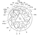
図12~図14に示されるように、本実施形態では、被係合部51の短辺部51aは、短辺部51aの径方向外側の端部E1とカム部材3の軸Xとを結んだ直線LNに対して第一方向D1側の領域で傾斜して延びている。すなわち、短辺部51aは、第1実施形態では、直線LNに対して第二方向D2側の領域に延びているのに対して、本実施形態では、直線LNに対して第一方向D1側の領域に延びている。本実施形態では、短辺部51aは、図12~図14に示されるように、短辺部51aの径方向外側の端部E1から、径方向内側に進むにつれて、直線LNとの間の距離が大きくなるように傾斜して延びている。なお、短辺部51aの径方向外側の端部E1は、短辺部51aと長辺部51bとが鋭角に交差している場合は、短辺部51aと長辺部51bとの間の交差部分とすることができる。また、本実施形態のように、短辺部51aと長辺部51bとの交差部分(底部51c)が湾曲してなだらかにつながっている場合は、その湾曲した部分と短辺部51aとの境界地点とすることができる。本実施形態では、短辺部51aに係合する第一係合部412aは、短辺部51aと同様に、係合状態で、直線LNに対して第一方向D1側の領域で傾斜して延びている。 As shown in FIGS. 12 to 14, in this embodiment, the short side portion 51a of the engaged portion 51 connects the radially outer end E1 of the short side portion 51a and the axis X of the cam member 3. It extends obliquely in a region on the first direction D1 side with respect to the straight line LN. That is, in the first embodiment, the short side portion 51a extends in the second direction D2 side with respect to the straight line LN, whereas in the present embodiment, the short side portion 51a extends in the first direction D1 side with respect to the straight line LN. It extends into the area of In the present embodiment, as shown in FIGS. 12 to 14, the short side portion 51a is radially inward from the radially outer end E1 of the short side portion 51a, and the distance between the short side portion 51a and the straight line LN is It extends at an angle so that it becomes larger. Note that when the short side 51a and the long side 51b intersect at an acute angle, the radially outer end E1 of the short side 51a is the intersection between the short side 51a and the long side 51b. It can be a part. Further, as in the present embodiment, when the intersection portion (bottom portion 51c) of the short side portion 51a and the long side portion 51b is curved and connected gently, the boundary between the curved portion and the short side portion 51a It can be a location. In this embodiment, like the short side portion 51a, the first engaging portion 412a that engages with the short side portion 51a is inclined in the region on the first direction D1 side with respect to the straight line LN in the engaged state. It is extending.

短辺部51aが、直線LNに対して第一方向D1側の領域で傾斜して延びていることにより、カム部材3を第二方向D2に回転させて、係合部材41を被係合部51から外すときに、第一係合部412aから短辺部51aに径方向内側の成分の力が加わりにくく、係合部材41が被係合部51に引っ掛かりにくく(係合部材41が軸部413周りに回転できずに被係合部51内で拘束される状態)、第二従動部材5を第一方向D1に回転させやすい。上述したように、係合部材41の爪部412を被係合部51から外すためには、短辺部51aに対向する爪部412の第一係合部412aから短辺部51aに力を加えて、第二従動部材5を第一方向D1にわずかに回転させる必要がある。この際、短辺部51aが、直線LNに対して第一方向D1側の領域で傾斜していることにより、係合部材41が係合解除状態へと回転する際に、短辺部51aに引っ掛かりにくく、爪部412から短辺部51aに加わる力によって、第二従動部材5を第一方向D1に回転させやすくなる。したがって、爪部412が被係合部51内で短辺部51aに引っ掛かって、被係合部51内から外れずに、係合解除状態へと移動できないといった不具合が生じることが抑制される。 Since the short side portion 51a extends obliquely in the region on the first direction D1 side with respect to the straight line LN, the cam member 3 can be rotated in the second direction D2, and the engaging member 41 can be moved to the engaged portion. 51, it is difficult for the force from the radially inner component to be applied from the first engaging part 412a to the short side part 51a, and the engaging member 41 is less likely to be caught on the engaged part 51 (the engaging member 41 is 413), the second driven member 5 is easily rotated in the first direction D1. As described above, in order to remove the claw portion 412 of the engaging member 41 from the engaged portion 51, force is applied to the short side portion 51a from the first engaging portion 412a of the claw portion 412 facing the short side portion 51a. In addition, it is necessary to rotate the second driven member 5 slightly in the first direction D1. At this time, since the short side portion 51a is inclined in the region on the first direction D1 side with respect to the straight line LN, when the engagement member 41 rotates to the disengaged state, the short side portion 51a It is difficult to get caught, and the force applied from the claw portion 412 to the short side portion 51a makes it easier to rotate the second driven member 5 in the first direction D1. Therefore, the problem that the claw portion 412 is caught on the short side portion 51a within the engaged portion 51 and cannot be moved to the disengaged state without coming off from the engaged portion 51 is suppressed.

また、本実施形態では、係合部材41が係合解除状態となるためには、係合部材41が、図14において、実線で示す状態から二点鎖線で示す位置まで移動する必要がある。そのため、爪部412の先端部412cは、図14において、軌跡Tを辿ることになる。このように爪部412の先端部412cが軌跡Tを辿って移動することにより、第二従動部材5は、短辺部51aの径方向内側の端部E2は、所定の回転角度で第一方向D1に移動する(図14におけるE21の位置を参照)。第1実施形態の場合も、係合部材41が係合状態から係合解除状態まで移動するときに、第二従動部材5が回転し、爪部412の先端部412cが軌跡Tを辿って移動したとき、短辺部51aの径方向内側の端部E2は、所定の回転角度で第一方向D1に移動し、図10および図11におけるE22の位置まで移動する。図14における移動後の端部E21の位置と、図10および図11における移動後の端部E22の位置からわかるように、本実施形態では、短辺部51aが、直線LNに対して第一方向D1側で傾斜して延びていることにより、直線LNに対して第二方向D2側の領域に延びている第1実施形態(図10参照)と比較して、係合部材41が係合解除状態となる際の第二従動部材5の回転角度をより小さくすることができる。したがって、たとえば、長尺部材OPから第二従動部材5に第二方向D2に力が加わる場合など、第二従動部材5を第一方向D1に回転させにくい場合であっても、係合部材41を係合解除状態へと容易に移動させることができる。 Further, in this embodiment, in order for the engagement member 41 to enter the disengaged state, the engagement member 41 needs to move from the state shown by the solid line to the position shown by the two-dot chain line in FIG. Therefore, the tip portion 412c of the claw portion 412 follows the trajectory T in FIG. As the distal end portion 412c of the claw portion 412 moves along the trajectory T in this manner, the second driven member 5 moves the radially inner end E2 of the short side portion 51a in the first direction at a predetermined rotation angle. Move to D1 (see position E21 in FIG. 14). Also in the case of the first embodiment, when the engagement member 41 moves from the engaged state to the disengaged state, the second driven member 5 rotates, and the tip 412c of the claw portion 412 moves along the trajectory T. At this time, the radially inner end E2 of the short side portion 51a moves in the first direction D1 at a predetermined rotation angle, and moves to the position E22 in FIGS. 10 and 11. As can be seen from the position of the end E21 after movement in FIG. 14 and the position of the end E22 after movement in FIGS. 10 and 11, in this embodiment, the short side 51a is the first By extending at an angle in the direction D1, the engagement member 41 is more easily engaged than in the first embodiment (see FIG. 10) in which it extends in a region on the second direction D2 side with respect to the straight line LN. The rotation angle of the second driven member 5 when entering the released state can be made smaller. Therefore, even if it is difficult to rotate the second driven member 5 in the first direction D1, such as when a force is applied from the elongated member OP to the second driven member 5 in the second direction D2, the engagement member 41 can be easily moved to the disengaged state.

なお、直線LNと、短辺部51aの径方向外側の端部E1と短辺部51aの径方向内側の端部E2とを結んだ直線とが為す角θ(以下、傾斜角度θという)は、短辺部51aが直線LNに対して第一方向D1側の領域で傾斜して延びていれば、特に限定されない。例えば、短辺部51aの傾斜角度θは、3~35°とすることができる。短辺部51aの傾斜角度θを3~35°とすることにより、係合部材41が係合解除状態へと回転する際に、短辺部51aに引っ掛かりにくく、爪部412から短辺部51aに加わる力によって、第二従動部材5を第一方向D1に回転させやすくなる。また、傾斜角度θは、15~35°とすることがより好ましい。傾斜角度θを15~35°とすることにより、より短辺部51aに引っ掛かりにくく、爪部412から短辺部51aに加わる力によって、第二従動部材5を第一方向D1に回転させやすくなるうえ、係合部材41が係合解除状態へ移動させるときの第二従動部材5の第一方向D1への回転角度をより小さくすることができる。 The angle θ (hereinafter referred to as inclination angle θ) between the straight line LN and the straight line connecting the radially outer end E1 of the short side 51a and the radially inner end E2 of the short side 51a is , there is no particular limitation as long as the short side portion 51a extends obliquely in the region on the first direction D1 side with respect to the straight line LN. For example, the inclination angle θ of the short side portion 51a may be 3 to 35°. By setting the inclination angle θ of the short side portion 51a to 3 to 35 degrees, when the engagement member 41 rotates to the disengaged state, it is difficult to get caught on the short side portion 51a, and the short side portion 51a is easily removed from the claw portion 412. The force applied thereto makes it easier to rotate the second driven member 5 in the first direction D1. Further, it is more preferable that the inclination angle θ is 15 to 35 degrees. By setting the inclination angle θ to 15 to 35 degrees, the second driven member 5 is less likely to be caught on the short side portion 51a, and the second driven member 5 can be easily rotated in the first direction D1 by the force applied from the claw portion 412 to the short side portion 51a. Moreover, the rotation angle of the second driven member 5 in the first direction D1 when the engagement member 41 is moved to the disengaged state can be made smaller.

また、本実施形態では、短辺部51aは、図14に示されるように、短辺部51aの中央領域に凹部CVを有している。短辺部51aには、短辺部51aと、短辺部51aに対向する第一係合部412aとの間の摺動性を高めるグリスが塗布され、この凹部CVにグリスが貯留される。そのため、短辺部51aと第一係合部412aとの間の摺動性を高めることができ、係合部材41が係合状態から係合解除状態となるときの動作を円滑にすることができる。 Furthermore, in this embodiment, the short side portion 51a has a recess CV in the central region of the short side portion 51a, as shown in FIG. The short side portion 51a is coated with grease that enhances the slidability between the short side portion 51a and the first engaging portion 412a facing the short side portion 51a, and the grease is stored in the recess CV. Therefore, the slidability between the short side portion 51a and the first engaging portion 412a can be improved, and the operation when the engaging member 41 changes from the engaged state to the disengaged state can be made smooth. can.

1 駆動装置
2 駆動部
21 モータ
22 出力軸
3 カム部材
31 カム部
31a 第一カム部
31b 第二カム部
31c 筒状体
32 接続部
32a 嵌合部
33 軸部
4 第一従動部材
41 係合部材
411 押圧部
411a 第一押圧部
411b 第二押圧部
412 爪部
412a 第一係合部
412b 第二係合部
412c 先端部
413 軸部
42 基部
42a 第一基部
42b 第二基部
5 第二従動部材
5a 本体
5b 端壁
51 被係合部
51a 短辺部
51b 長辺部
51c 底部
6 巻取部
7 伝動部材
Ax 軸部材
B 軸受部
BR 軸支部
C カム
CV 凹部
D 車椅子固定装置
D1 第一方向
D2 第二方向
E1 短辺部の径方向外側の端部
E2 短辺部の径方向内側の端部
E21、E22 移動後の短辺部の径方向内側の端部
G 歯車
H ハウジング
L1 係合部材の軸部から爪部の先端部までの長さ
L2 係合部材の軸部から被係合部の底部までの最短距離
LN 短辺部の径方向外側の端部とカム部材の軸とを結んだ直線
OP 操作対象(長尺部材)
OP1 ベルト
OP2 フック
P 突出部
SP バネ部材
T 爪部の先端部が移動する軌跡
WC 車椅子(固定対象)
X 軸
X2 第二の軸
1 Drive device 2 Drive part 21 Motor 22 Output shaft 3 Cam member 31 Cam part 31a First cam part 31b Second cam part 31c Cylindrical body 32 Connection part 32a Fitting part 33 Shaft part 4 First driven member 41 Engagement member 411 Pressing part 411a First pressing part 411b Second pressing part 412 Claw part 412a First engaging part 412b Second engaging part 412c Tip part 413 Shaft part 42 Base part 42a First base part 42b Second base part 5 Second driven member 5a Main body 5b End wall 51 Engaged part 51a Short side part 51b Long side part 51c Bottom part 6 Winding part 7 Transmission member Ax Shaft member B Bearing part BR Shaft support C Cam CV Recessed part D Wheelchair fixing device D1 First direction D2 Second Direction E1 Radially outer end of the short side E2 radially inner end of the short side E21, E22 radially inner end of the short side after movement G Gear H Housing L1 Shaft of engagement member L2 The shortest distance from the shaft of the engaging member to the bottom of the engaged part LN The straight line connecting the radially outer end of the short side and the axis of the cam member OP Operation target (long member)
OP1 Belt OP2 Hook P Projection SP Spring member T Trajectory along which the tip of the claw moves WC Wheelchair (fixed target)
X axis X2 second axis

Claims (6)

駆動部と、
前記駆動部の駆動力により第一方向と、前記第一方向の反対方向となる第二方向に回転するカム部材と、
前記カム部材の回転によって動作する係合部材を有し、前記カム部材に対して相対回転可能な第一従動部材と、
前記係合部材が係合する被係合部を有し、前記カム部材と前記第一従動部材と相対回転可能な第二従動部材と
を備え、
前記係合部材は、前記被係合部に係合する爪部と、前記カム部材が前記第一方向または前記第二方向に回転したときに、前記カム部材に押圧される押圧部とを有し、
前記押圧部は、前記カム部材が前記第一方向に回転したときに、前記カム部材に押圧されることによって、前記係合部材が前記第二従動部材と係合する係合状態となる第一押圧部と、前記カム部材が前記第二方向に回転したときに、前記カム部材に押圧されることによって、前記係合部材が前記第二従動部材との係合が解除される係合解除状態となる第二押圧部とを有し、
前記カム部材は、前記係合部材の第一押圧部を押圧することにより前記係合部材を係合状態とさせる第一カム部と、前記係合部材の第二押圧部を押圧することにより前記係合解除状態とさせる第二カム部とを有する駆動装置であって、
前記駆動装置が、長尺部材が巻き取りおよび繰り出される巻取部を備え、
前記第二従動部材の前記第一方向および前記第二方向への回転によって、前記長尺部材が巻き取りおよび繰り出され、
前記駆動装置は、前記長尺部材の一端を固定対象に係合して、前記長尺部材を巻き取ることにより前記固定対象を固定するように構成され、
前記カム部材が前記第一方向に回転したときに、前記係合部材が前記被係合部と係合して、前記第一従動部材および前記第二従動部材が前記第一方向に連動して回転し、
前記第二従動部材が前記第一方向に回転することによって、前記長尺部材が巻き取られて、前記長尺部材に張力がかかった状態で、前記固定対象が固定され、
前記カム部材が前記第二方向に回転したときに、前記係合部材が前記第二従動部材を前記第一方向にわずかに回転させながら、前記係合部材が係合解除状態へと移動して、前記第二従動部材が前記第一従動部材に対して相対回転可能となり、前記固定対象の固定状態が解除される、
駆動装置。
A drive unit;
a cam member that rotates in a first direction and a second direction opposite to the first direction by a driving force of the driving section;
a first driven member that has an engagement member that operates by rotation of the cam member and is rotatable relative to the cam member;
The engaging member has an engaged portion that engages, and includes a second driven member that is rotatable relative to the cam member and the first driven member,
The engaging member has a claw portion that engages with the engaged portion, and a pressing portion that is pressed against the cam member when the cam member rotates in the first direction or the second direction. death,
The pressing portion is configured to be pressed by the cam member when the cam member rotates in the first direction, thereby bringing the engaging member into an engaged state where the engaging member engages with the second driven member. a disengaged state in which the engagement member is disengaged from the second driven member by being pressed by the cam member when the pressing portion and the cam member rotate in the second direction; and a second pressing part,
The cam member includes a first cam portion that brings the engaging member into an engaged state by pressing a first pressing portion of the engaging member, and a first cam portion that brings the engaging member into an engaged state by pressing a second pressing portion of the engaging member. A drive device having a second cam portion that is brought into a disengaged state,
The drive device includes a winding section where the elongated member is wound up and unwound,
The elongated member is wound up and unwound by the rotation of the second driven member in the first direction and the second direction,
The driving device is configured to engage one end of the elongated member with a fixed object and wind up the elongated member to fix the fixed object,
When the cam member rotates in the first direction, the engaging member engages with the engaged portion, and the first driven member and the second driven member move in the first direction. rotate,
When the second driven member rotates in the first direction, the elongated member is wound up, and the object to be fixed is fixed in a state where tension is applied to the elongated member,
When the cam member rotates in the second direction, the engaging member moves to a disengaged state while slightly rotating the second driven member in the first direction. , the second driven member becomes rotatable relative to the first driven member, and the fixed state of the fixed object is released;
Drive device.
前記第一従動部材は、前記係合部材を回転可能に軸支する軸部を有し、
前記押圧部は、前記軸部から前記カム部材の軸へ向かって延び、
前記カム部材が前記第一方向に回転したときに、前記係合解除状態のときの前記係合部材の前記第一押圧部が、前記カム部材の前記第一カム部に押圧されて、前記係合部材の前記爪部が前記被係合部に係合するように前記軸部を中心に回転し、
前記カム部材が前記第二方向に回転したときに、前記係合状態のときの前記係合部材の前記第二押圧部が、前記カム部材の前記第二カム部に押圧されて、前記係合部材の前記爪部が前記被係合部からの係合が解除されるように前記軸部を中心に回転する、請求項1に記載の駆動装置。
The first driven member has a shaft portion that rotatably supports the engagement member,
The pressing portion extends from the shaft portion toward the shaft of the cam member,
When the cam member rotates in the first direction, the first pressing portion of the engaging member in the disengaged state is pressed by the first cam portion of the cam member, and the first pressing portion of the engaging member in the disengaged state is pressed by the first cam portion of the cam member. The claw portion of the mating member rotates around the shaft portion so as to engage with the engaged portion,
When the cam member rotates in the second direction, the second pressing portion of the engaging member in the engaged state is pressed by the second cam portion of the cam member, causing the engaging The drive device according to claim 1, wherein the claw portion of the member rotates around the shaft portion such that the claw portion is disengaged from the engaged portion.
前記第二従動部材は、前記第一従動部材に対して、前記カム部材の径方向外側に配置され、
前記第二従動部材の前記被係合部は、前記第一従動部材の外周に対向する内周面に、ラチェット歯状に形成され、ラチェット歯状の前記被係合部は、前記係合部材の前記爪部が前記被係合部に係合しているときに、前記爪部に対して前記第一方向側に設けられた短辺部と、前記短辺部の径方向外側の端部から前記第二方向に延びる長辺部とを有し、
前記被係合部の前記短辺部は、前記短辺部の径方向外側の端部と前記カム部材の軸とを結んだ直線に対して前記第一方向側の領域で傾斜して延びている、請求項1または2に記載の駆動装置。
The second driven member is disposed radially outward of the cam member with respect to the first driven member,
The engaged portion of the second driven member is formed in a ratchet tooth shape on the inner circumferential surface facing the outer circumference of the first driven member, and the ratchet tooth shaped engaged portion is formed on the inner peripheral surface facing the outer circumference of the first driven member. a short side portion provided on the first direction side with respect to the claw portion when the claw portion is engaged with the engaged portion; and a radially outer end of the short side portion. and a long side extending in the second direction from
The short side portion of the engaged portion extends obliquely in a region on the first direction side with respect to a straight line connecting the radially outer end of the short side portion and the axis of the cam member. The drive device according to claim 1 or 2.
前記短辺部の径方向外側の端部と前記カム部材の軸とを結んだ直線と、前記短辺部の径方向外側の端部と前記短辺部の径方向内側の端部とを結んだ直線とが為す角が、3~35°である、請求項3に記載の駆動装置。 A straight line connecting the radially outer end of the short side and the axis of the cam member, and a straight line connecting the radially outer end of the short side and the radially inner end of the short side. The drive device according to claim 3, wherein the angle formed by the elliptical line is 3 to 35°. 前記係合部材の前記爪部が、前記係合状態において、前記短辺部と係合する第一係合部を備え、
前記係合状態で、前記第一係合部は、前記短辺部の径方向外側の端部と前記カム部材の軸とを結んだ直線に対して前記第一方向側の領域で傾斜して延びている、請求項3または4に記載の駆動装置。
The claw portion of the engaging member includes a first engaging portion that engages with the short side portion in the engaged state,
In the engaged state, the first engaging portion is inclined in a region on the first direction side with respect to a straight line connecting the radially outer end of the short side portion and the axis of the cam member. 5. A drive device according to claim 3, wherein the drive device is elongated.
前記第二従動部材は、前記第一従動部材に対して、前記カム部材の径方向外側に配置され、
前記第二従動部材の前記被係合部は、前記第一従動部材の外周に対向する内周面に、ラチェット歯状に形成され、ラチェット歯状の前記被係合部は、前記係合部材の前記爪部が前記被係合部に係合しているときに、前記爪部に対して前記第一方向側に設けられた短辺部と、前記短辺部の径方向外側の端部から前記第二方向に延びる長辺部とを有し、
前記爪部は、前記短辺部と当接する第一係合部と、前記長辺部と当接する第二係合部とを有し、
前記爪部は、前記カム部材が第一押圧部を押圧したときに、前記短辺部と前記長辺部とに当接した状態で、前記第二従動部材の径方向外側方向を方向成分に含み、前記第二従動部材の前記第一従動部材に対する両方向の相対回転を規制する力を前記第二従動部材に付与する、請求項1~5のいずれか1項に記載の駆動装置。
The second driven member is disposed radially outward of the cam member with respect to the first driven member,
The engaged portion of the second driven member is formed in a ratchet tooth shape on the inner circumferential surface facing the outer circumference of the first driven member, and the ratchet tooth shaped engaged portion is formed on the inner peripheral surface facing the outer circumference of the first driven member. a short side portion provided on the first direction side with respect to the claw portion when the claw portion is engaged with the engaged portion; and a radially outer end of the short side portion. and a long side extending in the second direction from
The claw portion has a first engaging portion that comes into contact with the short side portion, and a second engaging portion that comes into contact with the long side portion,
When the cam member presses the first pressing portion, the pawl portion is in contact with the short side portion and the long side portion, and the claw portion has a radially outward direction of the second driven member as a direction component. The drive device according to any one of claims 1 to 5, further comprising: applying a force to the second driven member to restrict relative rotation of the second driven member in both directions with respect to the first driven member.
JP2020178945A 2019-10-29 2020-10-26 drive device Active JP7411532B2 (en)

Applications Claiming Priority (2)

Application Number Priority Date Filing Date Title
JP2019196446 2019-10-29

Publications (2)

Publication Number Publication Date
JP2021071196A JP2021071196A (en) 2021-05-06
JP7411532B2 true JP7411532B2 (en) 2024-01-11

Family

ID=75712757

Family Applications (1)

Application Number Title Priority Date Filing Date
JP2020178945A Active JP7411532B2 (en) 2019-10-29 2020-10-26 drive device

Country Status (1)

Country Link
JP (1) JP7411532B2 (en)

Citations (1)

* Cited by examiner, † Cited by third party
Publication number Priority date Publication date Assignee Title
JP2005289259A (en) 2004-04-01 2005-10-20 Tokai Rika Co Ltd Webbing winding device

Family Cites Families (3)

* Cited by examiner, † Cited by third party
Publication number Priority date Publication date Assignee Title
DE3047891C2 (en) * 1980-12-19 1982-09-02 Jean Walterscheid Gmbh, 5204 Lohmar One-way clutch
JPS5885424A (en) * 1981-11-17 1983-05-21 Canon Inc Film winding and rewinding device for camera
US5070978A (en) * 1990-04-19 1991-12-10 Pires Paul B One way drive device

Patent Citations (1)

* Cited by examiner, † Cited by third party
Publication number Priority date Publication date Assignee Title
JP2005289259A (en) 2004-04-01 2005-10-20 Tokai Rika Co Ltd Webbing winding device

Also Published As

Publication number Publication date
JP2021071196A (en) 2021-05-06

Similar Documents

Publication Publication Date Title
US8360130B2 (en) Active tension device for a window covering
JP3280339B2 (en) Chain transmission tensioner lever
JP6321537B2 (en) Film transfer tool
HU229711B1 (en) Belt tensioner with installation pin
JP2607289Y2 (en) Speed change device for bicycle
JP5944804B2 (en) Vehicle latch device
JP2009108909A (en) Tensioner lever for chain drive
JP2013217116A (en) Vehicular handle device
JP7411532B2 (en) drive device
JP2559946Y2 (en) Silent type reverse rotation prevention mechanism for fishing reels
JP2000055153A (en) Backlashless ratchet type tensioner
US20150224815A1 (en) Transfer tool and refill for transfer tool
JP7389068B2 (en) drive device
EP3476619B1 (en) Horizontal pulling type coating film transfer tool
JP6412768B2 (en) Tire carrier
JP5394829B2 (en) Transfer tool with mute reversal prevention mechanism
JPH07233684A (en) Rolling screen device
JP2991792B2 (en) Rotary retractor shaft pretensioner
JP6235831B2 (en) Transfer tool
US20220090570A1 (en) Rope reel for recoil starter, and recoil
JP2535459Y2 (en) Double bearing type reel
JPH08121557A (en) Tensioner
JP2008305114A (en) Wire cable with casing
JP3989283B2 (en) Reclining mechanism
JP2002281875A (en) Spinning reel for fishing

Legal Events

Date Code Title Description
A621 Written request for application examination

Free format text: JAPANESE INTERMEDIATE CODE: A621

Effective date: 20221014

A977 Report on retrieval

Free format text: JAPANESE INTERMEDIATE CODE: A971007

Effective date: 20230623

A131 Notification of reasons for refusal

Free format text: JAPANESE INTERMEDIATE CODE: A131

Effective date: 20230704

A521 Request for written amendment filed

Free format text: JAPANESE INTERMEDIATE CODE: A523

Effective date: 20230904

TRDD Decision of grant or rejection written
A01 Written decision to grant a patent or to grant a registration (utility model)

Free format text: JAPANESE INTERMEDIATE CODE: A01

Effective date: 20231212

A61 First payment of annual fees (during grant procedure)

Free format text: JAPANESE INTERMEDIATE CODE: A61

Effective date: 20231225

R150 Certificate of patent or registration of utility model

Ref document number: 7411532

Country of ref document: JP

Free format text: JAPANESE INTERMEDIATE CODE: R150