EP3901419A1 - Phonisches rad mit ausgangsspannungsabstimmung - Google Patents
Phonisches rad mit ausgangsspannungsabstimmung Download PDFInfo
- Publication number
- EP3901419A1 EP3901419A1 EP21175722.4A EP21175722A EP3901419A1 EP 3901419 A1 EP3901419 A1 EP 3901419A1 EP 21175722 A EP21175722 A EP 21175722A EP 3901419 A1 EP3901419 A1 EP 3901419A1
- Authority
- EP
- European Patent Office
- Prior art keywords
- phonic wheel
- physical configuration
- sensor
- projections
- position markers
- Prior art date
- Legal status (The legal status is an assumption and is not a legal conclusion. Google has not performed a legal analysis and makes no representation as to the accuracy of the status listed.)
- Pending
Links
- 238000000034 method Methods 0.000 claims description 26
- 239000003550 marker Substances 0.000 claims description 22
- 239000000463 material Substances 0.000 claims description 16
- 230000004044 response Effects 0.000 claims description 14
- 230000004907 flux Effects 0.000 description 12
- 239000007789 gas Substances 0.000 description 9
- 230000008859 change Effects 0.000 description 8
- 238000012545 processing Methods 0.000 description 8
- 238000001514 detection method Methods 0.000 description 5
- 230000003287 optical effect Effects 0.000 description 4
- 238000010586 diagram Methods 0.000 description 3
- 210000003746 feather Anatomy 0.000 description 3
- 238000005259 measurement Methods 0.000 description 3
- 238000012544 monitoring process Methods 0.000 description 3
- 230000009467 reduction Effects 0.000 description 3
- 230000003068 static effect Effects 0.000 description 3
- 239000003570 air Substances 0.000 description 2
- 239000012080 ambient air Substances 0.000 description 2
- 238000013459 approach Methods 0.000 description 2
- 239000000567 combustion gas Substances 0.000 description 2
- 238000004590 computer program Methods 0.000 description 2
- 230000006870 function Effects 0.000 description 2
- 238000012986 modification Methods 0.000 description 2
- 230000004048 modification Effects 0.000 description 2
- 238000002310 reflectometry Methods 0.000 description 2
- 230000006835 compression Effects 0.000 description 1
- 238000007906 compression Methods 0.000 description 1
- 230000004069 differentiation Effects 0.000 description 1
- 239000000446 fuel Substances 0.000 description 1
- 238000012804 iterative process Methods 0.000 description 1
- 238000012552 review Methods 0.000 description 1
- 239000004065 semiconductor Substances 0.000 description 1
Images


Classifications
-
- F—MECHANICAL ENGINEERING; LIGHTING; HEATING; WEAPONS; BLASTING
- F02—COMBUSTION ENGINES; HOT-GAS OR COMBUSTION-PRODUCT ENGINE PLANTS
- F02C—GAS-TURBINE PLANTS; AIR INTAKES FOR JET-PROPULSION PLANTS; CONTROLLING FUEL SUPPLY IN AIR-BREATHING JET-PROPULSION PLANTS
- F02C7/00—Features, components parts, details or accessories, not provided for in, or of interest apart form groups F02C1/00 - F02C6/00; Air intakes for jet-propulsion plants
-
- F—MECHANICAL ENGINEERING; LIGHTING; HEATING; WEAPONS; BLASTING
- F01—MACHINES OR ENGINES IN GENERAL; ENGINE PLANTS IN GENERAL; STEAM ENGINES
- F01D—NON-POSITIVE DISPLACEMENT MACHINES OR ENGINES, e.g. STEAM TURBINES
- F01D17/00—Regulating or controlling by varying flow
- F01D17/02—Arrangement of sensing elements
- F01D17/06—Arrangement of sensing elements responsive to speed
-
- F—MECHANICAL ENGINEERING; LIGHTING; HEATING; WEAPONS; BLASTING
- F01—MACHINES OR ENGINES IN GENERAL; ENGINE PLANTS IN GENERAL; STEAM ENGINES
- F01D—NON-POSITIVE DISPLACEMENT MACHINES OR ENGINES, e.g. STEAM TURBINES
- F01D21/00—Shutting-down of machines or engines, e.g. in emergency; Regulating, controlling, or safety means not otherwise provided for
- F01D21/003—Arrangements for testing or measuring
-
- B—PERFORMING OPERATIONS; TRANSPORTING
- B64—AIRCRAFT; AVIATION; COSMONAUTICS
- B64C—AEROPLANES; HELICOPTERS
- B64C11/00—Propellers, e.g. of ducted type; Features common to propellers and rotors for rotorcraft
- B64C11/30—Blade pitch-changing mechanisms
-
- B—PERFORMING OPERATIONS; TRANSPORTING
- B64—AIRCRAFT; AVIATION; COSMONAUTICS
- B64C—AEROPLANES; HELICOPTERS
- B64C11/00—Propellers, e.g. of ducted type; Features common to propellers and rotors for rotorcraft
- B64C11/30—Blade pitch-changing mechanisms
- B64C11/301—Blade pitch-changing mechanisms characterised by blade position indicating means
-
- B—PERFORMING OPERATIONS; TRANSPORTING
- B64—AIRCRAFT; AVIATION; COSMONAUTICS
- B64C—AEROPLANES; HELICOPTERS
- B64C11/00—Propellers, e.g. of ducted type; Features common to propellers and rotors for rotorcraft
- B64C11/46—Arrangements of, or constructional features peculiar to, multiple propellers
- B64C11/50—Phase synchronisation between multiple propellers
-
- B—PERFORMING OPERATIONS; TRANSPORTING
- B64—AIRCRAFT; AVIATION; COSMONAUTICS
- B64D—EQUIPMENT FOR FITTING IN OR TO AIRCRAFT; FLIGHT SUITS; PARACHUTES; ARRANGEMENT OR MOUNTING OF POWER PLANTS OR PROPULSION TRANSMISSIONS IN AIRCRAFT
- B64D31/00—Power plant control systems; Arrangement of power plant control systems in aircraft
- B64D31/02—Initiating means
- B64D31/06—Initiating means actuated automatically
- B64D31/12—Initiating means actuated automatically for equalising or synchronising power plants
-
- F—MECHANICAL ENGINEERING; LIGHTING; HEATING; WEAPONS; BLASTING
- F02—COMBUSTION ENGINES; HOT-GAS OR COMBUSTION-PRODUCT ENGINE PLANTS
- F02C—GAS-TURBINE PLANTS; AIR INTAKES FOR JET-PROPULSION PLANTS; CONTROLLING FUEL SUPPLY IN AIR-BREATHING JET-PROPULSION PLANTS
- F02C9/00—Controlling gas-turbine plants; Controlling fuel supply in air- breathing jet-propulsion plants
-
- G—PHYSICS
- G01—MEASURING; TESTING
- G01D—MEASURING NOT SPECIALLY ADAPTED FOR A SPECIFIC VARIABLE; ARRANGEMENTS FOR MEASURING TWO OR MORE VARIABLES NOT COVERED IN A SINGLE OTHER SUBCLASS; TARIFF METERING APPARATUS; MEASURING OR TESTING NOT OTHERWISE PROVIDED FOR
- G01D5/00—Mechanical means for transferring the output of a sensing member; Means for converting the output of a sensing member to another variable where the form or nature of the sensing member does not constrain the means for converting; Transducers not specially adapted for a specific variable
- G01D5/12—Mechanical means for transferring the output of a sensing member; Means for converting the output of a sensing member to another variable where the form or nature of the sensing member does not constrain the means for converting; Transducers not specially adapted for a specific variable using electric or magnetic means
- G01D5/14—Mechanical means for transferring the output of a sensing member; Means for converting the output of a sensing member to another variable where the form or nature of the sensing member does not constrain the means for converting; Transducers not specially adapted for a specific variable using electric or magnetic means influencing the magnitude of a current or voltage
- G01D5/142—Mechanical means for transferring the output of a sensing member; Means for converting the output of a sensing member to another variable where the form or nature of the sensing member does not constrain the means for converting; Transducers not specially adapted for a specific variable using electric or magnetic means influencing the magnitude of a current or voltage using Hall-effect devices
- G01D5/145—Mechanical means for transferring the output of a sensing member; Means for converting the output of a sensing member to another variable where the form or nature of the sensing member does not constrain the means for converting; Transducers not specially adapted for a specific variable using electric or magnetic means influencing the magnitude of a current or voltage using Hall-effect devices influenced by the relative movement between the Hall device and magnetic fields
-
- G—PHYSICS
- G01—MEASURING; TESTING
- G01L—MEASURING FORCE, STRESS, TORQUE, WORK, MECHANICAL POWER, MECHANICAL EFFICIENCY, OR FLUID PRESSURE
- G01L3/00—Measuring torque, work, mechanical power, or mechanical efficiency, in general
- G01L3/02—Rotary-transmission dynamometers
- G01L3/04—Rotary-transmission dynamometers wherein the torque-transmitting element comprises a torsionally-flexible shaft
- G01L3/10—Rotary-transmission dynamometers wherein the torque-transmitting element comprises a torsionally-flexible shaft involving electric or magnetic means for indicating
- G01L3/101—Rotary-transmission dynamometers wherein the torque-transmitting element comprises a torsionally-flexible shaft involving electric or magnetic means for indicating involving magnetic or electromagnetic means
-
- G—PHYSICS
- G01—MEASURING; TESTING
- G01P—MEASURING LINEAR OR ANGULAR SPEED, ACCELERATION, DECELERATION, OR SHOCK; INDICATING PRESENCE, ABSENCE, OR DIRECTION, OF MOVEMENT
- G01P3/00—Measuring linear or angular speed; Measuring differences of linear or angular speeds
- G01P3/42—Devices characterised by the use of electric or magnetic means
- G01P3/44—Devices characterised by the use of electric or magnetic means for measuring angular speed
- G01P3/48—Devices characterised by the use of electric or magnetic means for measuring angular speed by measuring frequency of generated current or voltage
- G01P3/481—Devices characterised by the use of electric or magnetic means for measuring angular speed by measuring frequency of generated current or voltage of pulse signals
-
- F—MECHANICAL ENGINEERING; LIGHTING; HEATING; WEAPONS; BLASTING
- F05—INDEXING SCHEMES RELATING TO ENGINES OR PUMPS IN VARIOUS SUBCLASSES OF CLASSES F01-F04
- F05D—INDEXING SCHEME FOR ASPECTS RELATING TO NON-POSITIVE-DISPLACEMENT MACHINES OR ENGINES, GAS-TURBINES OR JET-PROPULSION PLANTS
- F05D2240/00—Components
- F05D2240/20—Rotors
- F05D2240/24—Rotors for turbines
-
- F—MECHANICAL ENGINEERING; LIGHTING; HEATING; WEAPONS; BLASTING
- F05—INDEXING SCHEMES RELATING TO ENGINES OR PUMPS IN VARIOUS SUBCLASSES OF CLASSES F01-F04
- F05D—INDEXING SCHEME FOR ASPECTS RELATING TO NON-POSITIVE-DISPLACEMENT MACHINES OR ENGINES, GAS-TURBINES OR JET-PROPULSION PLANTS
- F05D2270/00—Control
- F05D2270/01—Purpose of the control system
- F05D2270/02—Purpose of the control system to control rotational speed (n)
Definitions
- the present disclosure relates generally to engines, and more specifically to propeller control systems for gas turbine engines.
- Certain types of phonic wheels can be used to provide information regarding the phase of rotation of the propeller, usually by removing one of the markers, creating a "missing tooth" which can be detected, or by adding an additional marker which is distinguishable from the other markers.
- existing approaches can lead to inaccurate measurements.
- a phonic wheel for use in a gas turbine engine, the phonic wheel comprising: a circular disk having first and second opposing faces, the circular disk defining a root surface that extends between and circumscribes the first and second faces; a first plurality of projections extending from the root surface and oriented substantially parallel to an axis of rotation of the disk, the first plurality of projections circumferentially spaced substantially equally from one another and each having a first physical configuration; and at least one second (or "supplementary") projection extending from the root surface and positioned between two adjacent first projections, the at least one second projection having a second physical configuration different from the first physical configuration.
- the at least one second projection having a second physical configuration different from the first physical configuration comprises the at least one second projection having a height greater than that the first plurality of projections.
- the at least one second projection having a second physical configuration different from the first physical configuration comprises the at least one second projection having a width greater than that of the first plurality of projections.
- the at least one second projection having a second physical configuration different from the first physical configuration comprises the at least one second projection having a shape different from that of the first plurality of projections.
- the at least one second projection having a second physical configuration different from the first physical configuration comprises the at least one second projection being fabricated from a material different than that from which the first plurality of projections are fabricated.
- the at least one second projection is positioned substantially equidistant between the two adjacent ones of the first plurality of projections.
- the at least one second projection is positioned closer to a particular one of the two adjacent ones of the first plurality of projections than to a second one thereof.
- the at least one second projection is disposed on the root surface at an angle relative to the first plurality of projections.
- the at least one second projection is disposed at a 45° angle relative to the first plurality of projections.
- a phonic wheel system for a gas turbine engine.
- the system comprises a phonic wheel and a sensor.
- the a phonic wheel comprises: a first plurality of projections extending from a root surface of the phonic wheel and oriented substantially parallel to an axis of rotation of the phonic wheel, the first plurality of projections circumferentially spaced substantially equally from one another and each having a first physical configuration; and at least one second projection extending from the root surface and positioned between two adjacent first projections, the at least one second projection having a second physical configuration different from the first physical configuration.
- the sensor is adjacent the phonic wheel and configured to sense passage of the first plurality of projections and the at least one second projection as the phonic wheel rotates.
- the senor is further configured for producing, in response to sensing the first plurality of projections and the at least one second projection, a signal pulse comprising a series of first pulses and at least one second pulse, wherein the at least one second pulse produced in response to sensing the at least one second projection is substantially equalized with the series of first pulses produced in response to sensing the first plurality of projections due to the second physical configuration being different from the first physical configuration.
- the senor in the sensor is configured for sensing within a sensing zone, wherein the second physical configuration being different from the first physical configuration causes a portion of the at least one second projection in the sensing zone to be substantially equivalent to a portion of one of the first projections to equalize the at least one second pulse with the series of first pulses.
- the at least one second projection having a second physical configuration different from the first physical configuration comprises the at least one second projection having at least one of a height, a width, and a shape different than that the first plurality of projections.
- the at least one second projection is positioned substantially equidistant between the two adjacent ones of the first plurality of projections.
- the at least one second projection is positioned closer to a particular one of the two adjacent ones of the first plurality of projections than to a second one thereof.
- the at least one second projection is disposed on the root surface at an angle relative to the first plurality of projections.
- the at least one second projection is disposed at a 45° angle relative to the first plurality of projections.
- a method for sensing a phonic wheel in a gas turbine engine comprising: producing a series of first signal pulses responsive to detecting, within a sensing zone of a sensor, a first plurality of projections extending from the root surface and circumferentially spaced substantially equally from one another, the first plurality of projections having a first physical configuration, the series of first signal pulses forming part of a signal; and producing at least one second signal pulse responsive to detecting, within the sensing zone of the sensor, at least one second projection extending from the root surface and positioned between two adjacent first projections, the at least one second projection having a second physical configuration different from the first physical configuration, the at least one second signal pulse forming part of the signal; the first and second signal pulses being equalized due to a portion of the at least one second projection sensed in the sensing zone being substantially equivalent to
- the at least one second signal pulse is produced responsive to detecting the at least one second projection having the second physical configuration comprising at least one of a second height, second width, and a second shape different from the first physical configuration comprising a corresponding at least one of a first height, a first width, and a first shape.
- the at least one second signal pulse is produced responsive to detecting the at least one second projection fabricated from a second material different than a first material from which the first plurality of projections are fabricated.
- a gas turbine engine having a phonic wheel assembly
- the phonic wheel assembly comprising: a phonic wheel having a first plurality of projections extending from a central disk root surface to a tip, the projections oriented substantially parallel to a disc axis of rotation, the first plurality of projections circumferentially spaced substantially equally from one another and each having a first tip shape, and at least one second projection extending from the root surface to a tip and positioned between two adjacent first projections, the second projection having a second tip shape different from the first tip shape; and a sensor adjacent the phonic wheel configured for sensing passage of the projections as the wheel rotates.
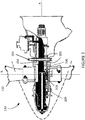
- Figure 1 depicts a gas turbine engine 110 of a type typically provided for use in subsonic flight.
- the engine 110 comprises an inlet 112 through which ambient air is propelled, a compressor section 114 for pressurizing the air, a combustor 116 in which the compressed air is mixed with fuel and ignited for generating an annular stream of hot combustion gases, and a turbine section 118 for extracting energy from the combustion gases.
- the turbine section 118 comprises a compressor turbine 120, which drives the compressor assembly and accessories, and at least one power or free turbine 122, which is independent from the compressor turbine 120 and rotatingly drives a rotor shaft 124 about a propeller shaft axis 'A' through a reduction gearbox 126. Hot gases may then be evacuated through exhaust stubs 128.
- the gas generator of the engine 110 comprises the compressor section 114, the combustor 116, and the turbine section 118.
- a rotor in the form of a propeller 130 through which ambient air is propelled, is hosted in a propeller hub 132.
- the rotor may, for example, comprise the propeller 130 of a fixed-wing aircraft, or a main (or tail) rotor of a rotary-wing aircraft such as a helicopter.
- the propeller 130 may comprise a plurality of circumferentially-arranged blades connected to a hub by any suitable means and extending radially therefrom. The blades are also each rotatable about their own radial axes through a plurality of blade angles, which can be changed to achieve modes of operation, such as feather, full reverse, and forward thrust.
- the system 200 provides for detection and measurement of rotational velocity of one or more rotating elements of the engine 110, for example the propeller 130, and of other propeller-related parameters, for instance propeller blade angle.
- the system 200 may interface to existing mechanical interfaces of typical propeller systems to provide a digital detection for electronic determination of the propeller blade angle.
- the present disclosure focuses on the use of the system 200 and the phonic wheel 204 in gas-turbine engines, similar techniques can be applied to other types of engines, including electric engines.
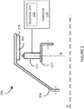
- the system 200 comprises an annular member 204 and one or more sensors 212 positioned proximate the annular member 204.
- Annular member 204 (referred to herein as a phonic wheel) has a plurality of position markers 202 provided thereon for detection by sensor 212.
- the phonic wheel 204 is mounted for rotation with propeller 130 and to move axially with adjustment of the blade angle of the blades of the propeller 130, and the sensor 212 is fixedly mounted to a static portion of the engine 110 and/or the propeller 130.
- the senor 212 is mounted for rotation with propeller 130 and to move axially with adjustment of the blade angle of the blades of the propeller 130, and the phonic wheel 204 is fixedly mounted to a static portion of the engine 110 and/or the propeller 130.
- the system 200 also includes a controller 220 communicatively coupled to the sensor 212.
- the sensor 212 is configured for producing a signal, for instance an electrical or optical signal, which is transmitted to or otherwise received by the controller 220, for example via a detection unit 222 thereof.
- the sensor 212 produces a series of signal pulses in response to detecting the presence of a position marker 202 in a sensing zone of the sensor 212.
- the sensor 212 operates on detecting changes in magnetic flux, and has a sensing zone which encompasses a circular or rectangular area or volume in front of the sensor 212.
- the magnetic flux in the sensing zone is varied by the presence of the position marker 202, and the sensor 212 can produce a signal pulse, which forms part of the signal.
- a side view of a portion of phonic wheel 204 and sensor 212 is shown.
- the sensor 212 is mounted to a flange 214 of a housing of the reduction gearbox 126, so as to be positioned adjacent the plurality of position markers 202.
- the sensor 212 is secured to the propeller 130 so as to extend away from the flange 214 and towards the position markers 202 along a radial direction, identified in Figure 2 as direction 'R'.
- Sensor 212 and flange 214 may be fixedly mounted, for example to the housing of the reduction gearbox 126, or to any other static element of the engine 110, as appropriate.
- a single sensor 212 is mounted in close proximity to the phonic wheel 204 and the position markers 202.
- one or more additional sensors which may be similar to the sensor 212, are provided.
- an additional sensor 212 may be mounted in a diametrically opposite relationship relative to the position markers 202, which extend away from the phonic wheel 204 and towards the sensor(s) 212.
- several position markers 202 may be spaced equiangularly about the perimeter of the phonic wheel 204. Other embodiments may apply.
- the phonic wheel 204 is embodied as a circular disk which rotates as part of the engine 110, for example with the output shaft 124 or with the propeller 130.
- the phonic wheel 204 comprises opposing faces 205 and defines a root surface 203 which extends between the opposing faces 205 and circumscribes them.
- the root surface 203 of the phonic wheel 204 is the outer periphery of the circular disk which spans between the two opposing faces 205.
- the position markers 202 can take the form of projections which extend from the root surface 203, as illustrated in Figures 4A-B and discussed in greater detail hereinbelow.
- the phonic wheel 204 is supported for rotation with the propeller 130, which rotates about the longitudinal axis 'A'.
- the phonic wheel 204 is also supported for longitudinal sliding movement along the axis A, e.g. by support members, such as a series of circumferentially spaced beta feedback rods 206 that extend along the longitudinal axis 'A'.
- a compression spring 208 surrounds an end portion of each rod 206.
- the propeller 130 comprises a plurality of angularly arranged blades 132, each of which is rotatable about a radially-extending axis 'R' through a plurality of adjustable blade angles, the blade angle being the angle between the chord line (i.e. a line drawn between the leading and trailing edges of the blade) of the propeller blade section and a plane perpendicular to the axis of propeller rotation.
- the propeller 130 is a reversing propeller, capable of operating in a variety of modes of operation, including feather, full reverse, and forward thrust.
- the blade angle may be positive or negative: the feather and forward thrust modes are associated with positive blade angles, and the full reverse mode is associated with negative blade angles.
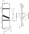
- the phonic wheel 204 comprises the position markers 202, which can take the form of projections which extend from the root surface 203. As the phonic wheel 204 rotates, varying portions thereof enter, pass through, and then exit the sensing zone of the sensor 212. From the perspective of the sensor 212, the phonic wheel moves along direction 'F' as the phonic wheel rotates.
- the position markers 202 include a plurality of projections 410 which are arranged along direction 'D', which is substantially transverse to the opposing faces 205. Although only two projections 410 are illustrated in Figure 4A , it should be understood that any suitable number of projections 410 may be present across the whole of the root surface 203.
- the projections 410 can be substantially equally spaced from one another on the root surface 203.
- the projections 410 are of substantially a common shape and size, for example having a common volumetric size.
- the phonic wheel 204 also includes at least one supplementary projection 420 which is positioned between two adjacent ones of the projections 410.
- the projection 420 is oriented along direction 'E', which is at an angle relative to direction 'D'.
- the angle between directions 'D' and 'E' can be any suitable value between 1° and 89°, for example 30°, 45°, 60°, or any other value, as appropriate.
- the supplementary projection 420 can be co-oriented with the projections 410, for instance along direction 'D', as shown in Figure 4A .
- the phonic wheel 204 includes only a single supplementary projection 420; in other embodiments, the phonic wheel 204 can include two, three, four, or more supplementary projections 420. In embodiments in which the phonic wheel 204 includes more than one supplementary projection 420, the supplementary projections can be oriented along a common orientation, for instance direction 'D', or can be oriented along one or more different orientations.
- the projection 420 can be located at substantially a midpoint between two adjacent projections 410, or can be located close to a particular one of two adjacent projections 410.
- the change in magnetic flux caused by the presence of the projection 420 may be different than that caused by the presence of the projection 410.
- the change in magnetic flux produced by the presence of the projection 420 may be less than the change in magnetic flux produced by the presence of one of the projections 410.
- the signal pulse (referred to herein as a second signal pulse) produced in response to the sensor 212 detecting the presence of the projection 420 may be smaller, or less pronounced, than a corresponding signal pulse (referred to herein as a first signal pulse) produced in response to the sensor 212 detecting the presence of the projection 410.
- the uneven nature of the first and second signal pulses can complicate signal processing of the signal produced by the sensor 212, for example for the controller 220, and can lead to inaccurate measurements.
- the projections 410 and the projection 420 are designed to have different physical configurations. That is to say, the projections 410 and the projection 420 can be of different shapes, different sizes, and/or made of different materials, so that the change in magnetic flux sensed by the sensor 212 and produced by the presence of the projection 420 in the sensing zone is substantially identical to the change in magnetic flux sensed by the sensor 212 and produced by the presence of any one of the projections 410.
- the projections 410, 420 extend to form a tip, and it is a tip shape of the projections 420 which is shaped differently from the tip shape of the projections 410.
- the projection 420 can have a dimension (e.g. a height, a width, and/or a length) that is greater than for the projections 410, such that the volumetric size of the projection 420 is greater than that of the projections 410.
- the projections 410 can be machined to be smaller, thinner, shorter, and/or of a different shape than the projections 420, and in some other cases, the projection 420 is formed to be taller, wider, longer, and/or of a different shape than the projections 410.
- the projection 420 can extend beyond a plane formed by one or both of the opposing faces 205. Any other suitable differentiation in dimensions between the projections 410, 420 is also considered.
- the sensor 212 may detect substantially the whole of one of the projections 410 when it enters the sensing zone of the sensor 212, but only a portion of the projection 420 when it enters the sensing zone.
- the portion of the projection 420 sensed by the sensor 212 in the sensing zone can be made comparable to that for the projections 410.
- the second signal pulse produced by the sensor 212 in response to the presence of the projection 420 can be tuned to be substantially equal to that produced in response to the presence of one of the projections 410.
- the terms “equal” and “equalize” are understood to refer to substantial equivalence to within a particular tolerance or range. For example, if the projections 410 produce electrical signal pulses having an amplitude of approximately 1 Volt (V), an electrical signal pulse produced by the projection 420 can be considered equal if it has an amplitude within a window of 1%, 5%, 10%, 15%, 20%, or any other suitable tolerance, around 1 V. For instance, if the projection 420 produces an electrical signal pulse with an amplitude of 0.95 V, this can be considered equal to the electrical signal pulse produced by the projections 410, and the magnetic flux response of the projections 410 and the projection 420 are said to be equalized.
- V Volt
- the shape of the projection 420, or the material of which it is composed, can be different than that of the projections 410.
- the projection 420 can be provided in a shape that increases the magnetic flux change observed by the sensor 212, such as a different rectangular shape, a trapezoidal shape, a pyramidal shape, and the like.
- the projection 420 can be fabricated with a material which produces a greater change in magnetic flux. For instance, if the projections 410 and the projection 420 are similarly sized, but the projection 420 is angled 45° with respect to the projections 410, the projection 420 can be made of a material which induces twice as much change in magnetic flux as the material used for the projections 410. Still other approaches are considered.
- the projection 420 is shown as being thicker than the projections 410.
- the projection 420 is shown as being taller than the projections 410.
- any combination of suitable changes to the projection 420, or to the projections 410, or both, can be employed in order to equalize the signal pulses produced by the sensor 212.
- the projection 420 can be both taller and wider than the projections 410.
- the projection 420 can be wider and of a different material than the projections 410. Still other combinations are considered.
- the dimensions of the projections 410 and/or the projection 420 is established iteratively, in order to produce projections 410, 420 which result in substantially equal signal pulses, when sensed by the sensor 212.
- the iterative process for determining the dimensions of the projections 410, 420 can be performed with physical phonic wheels and/or using modelling tools. Similar techniques can be applied when the material used to make the projections 410 and/or the projection 420 is varied.
- the signal pulses produced by the sensor 212 can be used to determine various operating parameters of the engine 110 and/or of the propeller 130.
- the series of first signal pulses can be indicative of the speed of rotation of the engine 110 and/or the propeller 130
- the second signal pulse can be indicative of a phase of the propeller 130.
- the sensor 212 which detects changes in magnetic flux due to the presence of one of the projections 410, 420 in the sensing zone of the sensor
- other types of sensors are also considered.
- an optical sensor which detects reflectivity of light off of position markers 202 can be used, and in this case the projections 420 can have a physical configuration which increases the reflectivity of the projections 420.
- an acoustic sensor which performs detection of position markers 202 using echoed sound waves can be used, and in this case the projections 420 can have a physical configuration which increases the degree to which incoming sound waves are reflected toward the acoustic sensor. Still other embodiments are considered.
- the present disclosure focuses primarily on embodiments in which the position markers 202 are projections, it should be noted that the techniques described herein may also be applied to other types of position markers 202.
- the position markers 202 are embedded in the circular disk portion of the phonic wheel 204, such that the phonic wheel 204 has a substantially smooth or uniform root surface 203.
- a position marker 202 can be a portion of the phonic wheel 204 which is made of a different material, or to which is applied a layer of a different material. The area of the different material can be varied in order to tune the pulses produced by the sensor 212. Still other embodiments are considered.
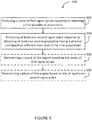
- a series of first signal pulses are produced via a sensor, for instance the sensor 212, in response to detecting a first plurality of projections, for example the projections 410.
- at least one second signal pulse is produced via the sensors 212 in response to detecting at least one second projection, for example the projection 420, which has a physical configuration different from that of the first projections.
- the time between sensing a first projection 410 and sensing the projection 420 can be substantially equal to the time between sensing the projection 420 and a sensing a subsequent one of the projections 410.
- the duration between detecting the particular projection 410 and the projection 420 may be shorter than the duration between detecting the projection 420 and the subsequent projection 410.
- a speed of the engine 110 and/or the propeller 130, and/or a phase of the propeller 130 can be determined based on the series of first signal pulses and based on the at least one second signal pulse, respectively.
- the method 500 may be implemented by a computing device 610, comprising a processing unit 612 and a memory 614 which has stored therein computer-executable instructions 616.
- the controller 220 may be embodied as the computing device 610.
- the processing unit 612 may comprise any suitable devices configured to implement the method 500 such that instructions 616, when executed by the computing device 610 or other programmable apparatus, may cause the functions/acts/steps performed as part of the method 500 as described herein to be executed.
- the processing unit 612 may comprise, for example, any type of general-purpose microprocessor or microcontroller, a digital signal processing (DSP) processor, a central processing unit (CPU), an integrated circuit, a field programmable gate array (FPGA), a reconfigurable processor, other suitably programmed or programmable logic circuits, or any combination thereof.
- DSP digital signal processing
- CPU central processing unit
- FPGA field programmable gate array
- reconfigurable processor other suitably programmed or programmable logic circuits, or any combination thereof.
- the memory 614 may comprise any suitable known or other machine-readable storage medium.
- the memory 614 may comprise non-transitory computer readable storage medium, for example, but not limited to, an electronic, magnetic, optical, electromagnetic, infrared, or semiconductor system, apparatus, or device, or any suitable combination of the foregoing.
- the memory 614 may include a suitable combination of any type of computer memory that is located either internally or externally to device, for example random-access memory (RAM), read-only memory (ROM), compact disc read-only memory (CDROM), electro-optical memory, magneto-optical memory, erasable programmable read-only memory (EPROM), and electrically-erasable programmable read-only memory (EEPROM), Ferroelectric RAM (FRAM) or the like.
- Memory 614 may comprise any storage means (e.g., devices) suitable for retrievably storing machine-readable instructions 616 executable by processing unit 612.
- the computing device 610 may be implemented as part of a FADEC or other similar device, including electronic engine control (EEC), engine control unit (EUC), and the like.
- EEC electronic engine control
- EUC engine control unit
- the method 500 and, more generally, the techniques described herein can be performed substantially in real-time, during operation of the engine 110.
- the monitoring of the engine 110 can be performed in real-time during a flight mission. The results of the monitoring can be reported to the operator and adjustments to the operational parameters of the engine 110 can also be performed in real-time.
- the phonic wheel and related systems and methods described herein may be implemented in a high level procedural or object oriented programming or scripting language, or a combination thereof, to communicate with or assist in the operation of a computer system, for example the computing device 610.
- the methods and systems described herein may be implemented in assembly or machine language.
- the language may be a compiled or interpreted language.
- Program code for implementing the methods and systems described herein may be stored on a storage media or a device, for example a ROM, a magnetic disk, an optical disc, a flash drive, or any other suitable storage media or device.
- the program code may be readable by a general or special-purpose programmable computer for configuring and operating the computer when the storage media or device is read by the computer to perform the procedures described herein.
- Embodiments of the methods and systems described herein may also be considered to be implemented by way of a non-transitory computer-readable storage medium having a computer program stored thereon.
- the computer program may comprise computer-readable instructions which cause a computer, or more specifically the processing unit 612 of the computing device 610, to operate in a specific and predefined manner to perform the functions described herein, for example those described in the method 500.
- Computer-executable instructions may be in many forms, including program modules, executed by one or more computers or other devices.
- program modules include routines, programs, objects, components, data structures, etc., that perform particular tasks or implement particular abstract data types.
- functionality of the program modules may be combined or distributed as desired in various embodiments.
Landscapes
- Engineering & Computer Science (AREA)
- Chemical & Material Sciences (AREA)
- Combustion & Propulsion (AREA)
- Mechanical Engineering (AREA)
- General Engineering & Computer Science (AREA)
- Physics & Mathematics (AREA)
- Aviation & Aerospace Engineering (AREA)
- General Physics & Mathematics (AREA)
- Electromagnetism (AREA)
- Transmission And Conversion Of Sensor Element Output (AREA)
Applications Claiming Priority (2)
| Application Number | Priority Date | Filing Date | Title |
|---|---|---|---|
| US16/023,072 US10801360B2 (en) | 2018-06-29 | 2018-06-29 | Phonic wheel with output voltage tuning |
| EP19183738.4A EP3587744B1 (de) | 2018-06-29 | 2019-07-01 | Phonisches rad mit ausgangsspannungsabstimmung |
Related Parent Applications (1)
| Application Number | Title | Priority Date | Filing Date |
|---|---|---|---|
| EP19183738.4A Division EP3587744B1 (de) | 2018-06-29 | 2019-07-01 | Phonisches rad mit ausgangsspannungsabstimmung |
Publications (1)
| Publication Number | Publication Date |
|---|---|
| EP3901419A1 true EP3901419A1 (de) | 2021-10-27 |
Family
ID=67139644
Family Applications (2)
| Application Number | Title | Priority Date | Filing Date |
|---|---|---|---|
| EP19183738.4A Active EP3587744B1 (de) | 2018-06-29 | 2019-07-01 | Phonisches rad mit ausgangsspannungsabstimmung |
| EP21175722.4A Pending EP3901419A1 (de) | 2018-06-29 | 2019-07-01 | Phonisches rad mit ausgangsspannungsabstimmung |
Family Applications Before (1)
| Application Number | Title | Priority Date | Filing Date |
|---|---|---|---|
| EP19183738.4A Active EP3587744B1 (de) | 2018-06-29 | 2019-07-01 | Phonisches rad mit ausgangsspannungsabstimmung |
Country Status (5)
| Country | Link |
|---|---|
| US (1) | US10801360B2 (de) |
| EP (2) | EP3587744B1 (de) |
| CN (1) | CN110657029A (de) |
| CA (1) | CA3044240A1 (de) |
| PL (1) | PL3587744T3 (de) |
Families Citing this family (2)
| Publication number | Priority date | Publication date | Assignee | Title |
|---|---|---|---|---|
| US10287006B1 (en) * | 2015-12-18 | 2019-05-14 | Amazon Technologies, Inc. | Adjustable propeller blades for sound control |
| US10829201B2 (en) * | 2019-03-20 | 2020-11-10 | Pratt & Whitney Canada Corp. | Blade angle position feedback system with extended markers |
Citations (5)
| Publication number | Priority date | Publication date | Assignee | Title |
|---|---|---|---|---|
| EP2876046A1 (de) * | 2013-11-21 | 2015-05-27 | Pratt & Whitney Canada Corp. | System und Verfahren zur elektronischen Propellerblattwinkelpositionsrückkopplung |
| EP3109409A1 (de) * | 2015-06-23 | 2016-12-28 | General Electric Company | Relative positionsmessung |
| EP3128332A2 (de) * | 2015-07-14 | 2017-02-08 | Weston Aerospace Limited | Magnetisches messsystem und verfahren zur wellengeschwindigkeitserkennung |
| EP3284666A1 (de) * | 2016-08-17 | 2018-02-21 | Pratt & Whitney Canada Corp. | Vorrichtung und verfahren zur flugzeugpropellersteuerung |
| EP3284665A1 (de) * | 2016-08-17 | 2018-02-21 | Pratt & Whitney Canada Corp. | System und verfahren für elektronische propellerblattwinkelpositionsrückmeldung mit abgewinkelten paaren von zähnen |
Family Cites Families (10)
| Publication number | Priority date | Publication date | Assignee | Title |
|---|---|---|---|---|
| JPS5436961A (en) * | 1977-08-29 | 1979-03-19 | Nissan Motor | Angleeoffrotation detector |
| GB8706905D0 (en) * | 1987-03-24 | 1987-04-29 | Schlumberger Electronics Uk | Shaft monitoring system |
| JP3368681B2 (ja) * | 1994-09-13 | 2003-01-20 | 株式会社デンソー | 磁気検出装置 |
| JPH10111144A (ja) * | 1996-10-04 | 1998-04-28 | Keihin Seiki Mfg Co Ltd | クランク軸回転基準位置検出装置 |
| FR2931552B1 (fr) | 2008-05-21 | 2010-07-30 | Turbomeca | Dispositif de mesure de couple transmis par un arbre de puissance |
| FR2944050B1 (fr) * | 2009-04-02 | 2014-07-11 | Turbomeca | Roue de turbine a pales desaccordees comportant un dispositif d'amortissement |
| FR2968038B1 (fr) * | 2010-11-26 | 2012-12-28 | Snecma | Systeme de detection d'un evenement fugace sur une roue aubagee de moteur d'aeronef |
| CN102785742B (zh) * | 2012-07-28 | 2014-02-05 | 成都宽和科技有限责任公司 | 飞轮上设多磁块不均匀分布磁通量传感器的助力自行车 |
| GB201611524D0 (en) | 2016-07-01 | 2016-08-17 | Rolls Royce Plc | Rotor blade damage |
| CN106771324B (zh) * | 2017-01-19 | 2023-08-11 | 中国第一汽车股份有限公司 | 抗干扰霍尔式转速传感器磁场探测结构及信号处理方法 |
-
2018
- 2018-06-29 US US16/023,072 patent/US10801360B2/en active Active
-
2019
- 2019-05-23 CA CA3044240A patent/CA3044240A1/en active Pending
- 2019-07-01 CN CN201910584824.0A patent/CN110657029A/zh active Pending
- 2019-07-01 EP EP19183738.4A patent/EP3587744B1/de active Active
- 2019-07-01 PL PL19183738T patent/PL3587744T3/pl unknown
- 2019-07-01 EP EP21175722.4A patent/EP3901419A1/de active Pending
Patent Citations (5)
| Publication number | Priority date | Publication date | Assignee | Title |
|---|---|---|---|---|
| EP2876046A1 (de) * | 2013-11-21 | 2015-05-27 | Pratt & Whitney Canada Corp. | System und Verfahren zur elektronischen Propellerblattwinkelpositionsrückkopplung |
| EP3109409A1 (de) * | 2015-06-23 | 2016-12-28 | General Electric Company | Relative positionsmessung |
| EP3128332A2 (de) * | 2015-07-14 | 2017-02-08 | Weston Aerospace Limited | Magnetisches messsystem und verfahren zur wellengeschwindigkeitserkennung |
| EP3284666A1 (de) * | 2016-08-17 | 2018-02-21 | Pratt & Whitney Canada Corp. | Vorrichtung und verfahren zur flugzeugpropellersteuerung |
| EP3284665A1 (de) * | 2016-08-17 | 2018-02-21 | Pratt & Whitney Canada Corp. | System und verfahren für elektronische propellerblattwinkelpositionsrückmeldung mit abgewinkelten paaren von zähnen |
Also Published As
| Publication number | Publication date |
|---|---|
| EP3587744B1 (de) | 2021-05-26 |
| EP3587744A1 (de) | 2020-01-01 |
| PL3587744T3 (pl) | 2021-10-04 |
| CA3044240A1 (en) | 2019-12-29 |
| CN110657029A (zh) | 2020-01-07 |
| US10801360B2 (en) | 2020-10-13 |
| US20200003074A1 (en) | 2020-01-02 |
Similar Documents
| Publication | Publication Date | Title |
|---|---|---|
| US10745110B2 (en) | Propeller blade synchrophasing using phonic wheel | |
| EP3284665B1 (de) | System und verfahren für elektronische propellerblattwinkelpositionsrückmeldung mit abgewinkelten paaren von zähnen | |
| US11554850B2 (en) | Blade angle position feedback system with offset sensors | |
| US11835543B2 (en) | Blade angle position feedback system with embedded markers | |
| US11685514B2 (en) | Pitch control assembly for an aircraft-bladed rotor | |
| EP3591409A1 (de) | Verfahren und system zum steuern einer überschreitungsschwelle zum bestimmen der drehzahl eines propellers | |
| EP3587744B1 (de) | Phonisches rad mit ausgangsspannungsabstimmung | |
| EP3838745A1 (de) | System und verfahren zur bestimmung einer axialen position einer rückkopplungsvorrichtung | |
| EP3789292A1 (de) | Signalverstärkung in einem system zur rückmeldung der schaufelwinkelposition | |
| US20210246840A1 (en) | Systems and methods for engine calibration |
Legal Events
| Date | Code | Title | Description |
|---|---|---|---|
| PUAI | Public reference made under article 153(3) epc to a published international application that has entered the european phase |
Free format text: ORIGINAL CODE: 0009012 |
|
| STAA | Information on the status of an ep patent application or granted ep patent |
Free format text: STATUS: THE APPLICATION HAS BEEN PUBLISHED |
|
| AC | Divisional application: reference to earlier application |
Ref document number: 3587744 Country of ref document: EP Kind code of ref document: P |
|
| AK | Designated contracting states |
Kind code of ref document: A1 Designated state(s): AL AT BE BG CH CY CZ DE DK EE ES FI FR GB GR HR HU IE IS IT LI LT LU LV MC MK MT NL NO PL PT RO RS SE SI SK SM TR |
|
| B565 | Issuance of search results under rule 164(2) epc |
Effective date: 20210928 |
|
| STAA | Information on the status of an ep patent application or granted ep patent |
Free format text: STATUS: REQUEST FOR EXAMINATION WAS MADE |
|
| 17P | Request for examination filed |
Effective date: 20220318 |
|
| RBV | Designated contracting states (corrected) |
Designated state(s): AL AT BE BG CH CY CZ DE DK EE ES FI FR GB GR HR HU IE IS IT LI LT LU LV MC MK MT NL NO PL PT RO RS SE SI SK SM TR |
|
| REG | Reference to a national code |
Ref country code: DE Ref legal event code: R079 Free format text: PREVIOUS MAIN CLASS: F01D0017060000 Ipc: B64C0011500000 |
|
| RIC1 | Information provided on ipc code assigned before grant |
Ipc: F01D 17/06 20060101ALI20231030BHEP Ipc: B64C 11/30 20060101ALI20231030BHEP Ipc: G01P 3/481 20060101ALI20231030BHEP Ipc: G01D 5/14 20060101ALI20231030BHEP Ipc: B64D 31/12 20060101ALI20231030BHEP Ipc: B64C 11/50 20060101AFI20231030BHEP |
|
| GRAP | Despatch of communication of intention to grant a patent |
Free format text: ORIGINAL CODE: EPIDOSNIGR1 |
|
| STAA | Information on the status of an ep patent application or granted ep patent |
Free format text: STATUS: GRANT OF PATENT IS INTENDED |
|
| INTG | Intention to grant announced |
Effective date: 20231212 |
|
| GRAJ | Information related to disapproval of communication of intention to grant by the applicant or resumption of examination proceedings by the epo deleted |
Free format text: ORIGINAL CODE: EPIDOSDIGR1 |
|
| STAA | Information on the status of an ep patent application or granted ep patent |
Free format text: STATUS: REQUEST FOR EXAMINATION WAS MADE |
|
| GRAP | Despatch of communication of intention to grant a patent |
Free format text: ORIGINAL CODE: EPIDOSNIGR1 |
|
| STAA | Information on the status of an ep patent application or granted ep patent |
Free format text: STATUS: GRANT OF PATENT IS INTENDED |
|
| INTC | Intention to grant announced (deleted) |