EP3901375A2 - Support assembly - Google Patents
Support assembly Download PDFInfo
- Publication number
- EP3901375A2 EP3901375A2 EP21161957.2A EP21161957A EP3901375A2 EP 3901375 A2 EP3901375 A2 EP 3901375A2 EP 21161957 A EP21161957 A EP 21161957A EP 3901375 A2 EP3901375 A2 EP 3901375A2
- Authority
- EP
- European Patent Office
- Prior art keywords
- carrier unit
- support
- post
- peg
- holding plate
- Prior art date
- Legal status (The legal status is an assumption and is not a legal conclusion. Google has not performed a legal analysis and makes no representation as to the accuracy of the status listed.)
- Granted
Links
- 230000035515 penetration Effects 0.000 claims abstract description 17
- 238000004873 anchoring Methods 0.000 claims abstract description 3
- 239000000758 substrate Substances 0.000 claims description 6
- 229910000831 Steel Inorganic materials 0.000 description 7
- 238000010276 construction Methods 0.000 description 7
- 239000010959 steel Substances 0.000 description 7
- 230000006641 stabilisation Effects 0.000 description 5
- 238000011105 stabilization Methods 0.000 description 5
- 239000000463 material Substances 0.000 description 4
- 230000008439 repair process Effects 0.000 description 4
- 230000003068 static effect Effects 0.000 description 4
- 239000004567 concrete Substances 0.000 description 3
- 238000003780 insertion Methods 0.000 description 3
- 230000037431 insertion Effects 0.000 description 3
- 239000002184 metal Substances 0.000 description 3
- 229910052751 metal Inorganic materials 0.000 description 3
- XEEYBQQBJWHFJM-UHFFFAOYSA-N Iron Chemical compound [Fe] XEEYBQQBJWHFJM-UHFFFAOYSA-N 0.000 description 2
- 239000002969 artificial stone Substances 0.000 description 2
- 238000005452 bending Methods 0.000 description 2
- 239000011449 brick Substances 0.000 description 2
- 239000004927 clay Substances 0.000 description 2
- 238000011161 development Methods 0.000 description 2
- 230000018109 developmental process Effects 0.000 description 2
- 238000005553 drilling Methods 0.000 description 2
- 238000012545 processing Methods 0.000 description 2
- 239000004576 sand Substances 0.000 description 2
- 239000007787 solid Substances 0.000 description 2
- 239000004575 stone Substances 0.000 description 2
- 238000003466 welding Methods 0.000 description 2
- 229910000746 Structural steel Inorganic materials 0.000 description 1
- 229910000870 Weathering steel Inorganic materials 0.000 description 1
- 238000013459 approach Methods 0.000 description 1
- 239000000969 carrier Substances 0.000 description 1
- 230000002950 deficient Effects 0.000 description 1
- 238000012407 engineering method Methods 0.000 description 1
- 239000004744 fabric Substances 0.000 description 1
- 230000005484 gravity Effects 0.000 description 1
- 238000009434 installation Methods 0.000 description 1
- 229910052742 iron Inorganic materials 0.000 description 1
- 238000012423 maintenance Methods 0.000 description 1
- 239000000203 mixture Substances 0.000 description 1
- 230000000877 morphologic effect Effects 0.000 description 1
- 230000002787 reinforcement Effects 0.000 description 1
- 230000000284 resting effect Effects 0.000 description 1
- 239000000126 substance Substances 0.000 description 1
- 239000013589 supplement Substances 0.000 description 1
- 239000002023 wood Substances 0.000 description 1
Images


Classifications
-
- E—FIXED CONSTRUCTIONS
- E02—HYDRAULIC ENGINEERING; FOUNDATIONS; SOIL SHIFTING
- E02D—FOUNDATIONS; EXCAVATIONS; EMBANKMENTS; UNDERGROUND OR UNDERWATER STRUCTURES
- E02D5/00—Bulkheads, piles, or other structural elements specially adapted to foundation engineering
- E02D5/74—Means for anchoring structural elements or bulkheads
- E02D5/80—Ground anchors
-
- E—FIXED CONSTRUCTIONS
- E02—HYDRAULIC ENGINEERING; FOUNDATIONS; SOIL SHIFTING
- E02D—FOUNDATIONS; EXCAVATIONS; EMBANKMENTS; UNDERGROUND OR UNDERWATER STRUCTURES
- E02D27/00—Foundations as substructures
- E02D27/32—Foundations for special purposes
- E02D27/42—Foundations for poles, masts or chimneys
-
- E—FIXED CONSTRUCTIONS
- E04—BUILDING
- E04H—BUILDINGS OR LIKE STRUCTURES FOR PARTICULAR PURPOSES; SWIMMING OR SPLASH BATHS OR POOLS; MASTS; FENCING; TENTS OR CANOPIES, IN GENERAL
- E04H12/00—Towers; Masts or poles; Chimney stacks; Water-towers; Methods of erecting such structures
- E04H12/22—Sockets or holders for poles or posts
- E04H12/2207—Sockets or holders for poles or posts not used
- E04H12/2215—Sockets or holders for poles or posts not used driven into the ground
- E04H12/223—Sockets or holders for poles or posts not used driven into the ground with movable anchoring elements; with separately driven anchor rods
-
- E—FIXED CONSTRUCTIONS
- E04—BUILDING
- E04H—BUILDINGS OR LIKE STRUCTURES FOR PARTICULAR PURPOSES; SWIMMING OR SPLASH BATHS OR POOLS; MASTS; FENCING; TENTS OR CANOPIES, IN GENERAL
- E04H17/00—Fencing, e.g. fences, enclosures, corrals
- E04H17/14—Fences constructed of rigid elements, e.g. with additional wire fillings or with posts
- E04H17/20—Posts therefor
- E04H17/22—Anchoring means therefor, e.g. specially-shaped parts entering the ground; Struts or the like
Definitions
- the subject of the invention is a support arrangement for receiving and supporting posts, technical structures and masonry according to the preambles of claims 1 and 7.
- a post is used to denote either an elongated support element installed vertically in buildings or a free-standing elongated, vertical structural element connected to the subsurface.
- a post support arrangement is understood to mean a device for fastening and supporting a structure, in particular a rod-shaped, post-shaped or tubular object.
- Masonry is a component or structure made of natural or artificial stones as a solid structure.
- the masonry consists of individual pressure-resistant elements (natural stones or artificial stones such as clay bricks, masonry bricks or hollow blocks).
- a wall support arrangement is understood to mean a device for fastening and supporting a wall, in particular a flat, vertically extending wall.
- a peg is preferably inserted into the ground.
- a peg is preferably to be understood as a round metal rod, the outer jacket of which is provided with a thread profile over the entire length of its course.
- Such pegs can, regardless of their material properties, not only be built on the basis of a round rod, but also have an angular or oval cross-section or, in addition to a continuously smooth surface, also have a connection of several profiles.
- ground nails can be used for drilling-like penetration of materials which, according to their morphology, allow the penetration of such a nail.
- pegs can be driven into layers of material made of sand, rubble, snow, ice, gravel, stone or their mixtures with one another.
- the ideal case is a primer made of e.g. snow, ice, sand, earth or clay, whereby a peg follows the pulling direction of its thread profile when it is screwed in and finds the desired hold in the primer.
- the insertion of the peg into the subsoil depends on the morphological nature of the subsoil and can optionally be carried out by pre-drilling in the intended depth and inclination. This is also possible without pre-drilling, in that the external thread of the peg takes on the function of a drill thread and works into or loosens from the ground under vertical pressure or tension.
- the stability of a masonry or a general structural device is characterized by the statics, but also by the foundation of the same. If one of these components is neglected during the planning or creation of the construction project, the safe maintenance and thus the function of the entire construction project is no longer guaranteed.
- ground anchors For such structural repair measures of this magnitude, the inclusion of an already existing foundation is necessary in most cases. If this can no longer be used or if it has to be partially replaced, conventional ground anchors must be used, which, as earth screws or impact elements, are able to centrally absorb the pressure of loads and anchor them in a narrow catchment area.
- Such an assembly can only be carried out if there is a vertical free space above the peg to be inserted or can be opened so that such a screw or hammer nail can be screwed in or hammered in with a hydraulic or similar device.
- Such framework conditions are only given in rare cases.
- pegs for a support arrangement is also known for stiffening wooden structures, wooden piles, overhead line masts and the like, which have become damaged as a result of the weather.
- a concrete body is used in a pit next to the defective mast, which has a metal support structure at its upper end, which is screwed to the mast.
- the damaged part of the mast is then sawn out below the fastening point so that the mast is now supported with the iron struts of the concrete body.
- pegs are also used, as it is for example with the support arrangement of the US 278 220 A is shown.
- the mast to be fixed has a flat foundation, with which the mast stands on the ground.
- This flat foundation has slots on its outer arms through which the peg can be driven in order to anchor the mast to the ground.
- the post has a kind of sleeve to which the receiving arms are welded like wings.
- the receiving sleeve or the foundation is inserted into the subsoil below the top of the terrain.
- a hole is first dug into which the post with the post support structure is placed, which is then provided with the receiving sleeve.
- Subsequent insertion of the pegs on the side of the sleeve creates an anchor arrangement and then the previously dug hole in which the post is located is filled in again, so that the anchor arrangement is buried in the ground.
- the present invention is therefore based on the object of designing a support arrangement for receiving and supporting posts and masonry in such a way that there is a foundation that is easy to introduce into the subsurface and dimensioned according to the expected forces.
- the support arm protruding from the support arrangement is designed as a flat holding plate which has several penetration openings in each of which a movable spherical body is arranged through which a peg is passed and that the spherical body is between an upper holding plate and the lower flat holding plate is clamped in a secured position.
- the arrangement according to the invention thus serves as a decentralized foundation and securing system, which can absorb the so-called gravity pressure in any lateral positioning to a post or masonry and can derive it laterally with any direction and distance in a simple manner or over several vertical planes.
- a completely new and at the same time relieving foundation is possible.
- Horizontal loads can be transferred into the subsoil by means of pegs that are guided through the retaining plate and inserted into the subsoil
- the support arrangement according to the invention is particularly suitable for transferring large loads.
- the upper holding plate which is screwed to the lower holding plate, also has an opening through which the spherical body partially protrudes.
- the spherical body has a holding stub with an internal thread through which a rotational movement applied to the holding connector can be transmitted to the thread of the peg.
- the post support structure thus consists of a carrier unit which is vertically inserted into the subsurface and on which at least two retaining plates are mounted on the sides.
- Steel girders made of weatherproof structural steel are preferably used for the support arrangement as a carrier unit.
- Steel girders are either rolled or welded profiles that are available in various sizes and designs. These are load-bearing components that are particularly robust due to their nature, have a high load-bearing capacity and load-bearing capacity and can be used flexibly.
- So-called double-T beams are preferably used, which have an upper flange and a lower flange connected to it via a web.
- supports can also be used which, for example, have a U-profile.
- these flanges are generally referred to as belts
- the upper and lower belts of a beam with a double-T-shaped cross-section, which are held at a distance from the continuous web are referred to as belts in concrete, wood and steel construction.
- these belts absorb the load from bending.
- the retaining plates can now be attached laterally in any number, which have any number of openings through which the pegs (preferably made of steel) in the form of smooth round rods or Threaded rods can be inserted in any orientation using simple screwing or striking tools and can be firmly connected by screwing or welding.
- the pegs preferably made of steel
- Threaded rods can be inserted in any orientation using simple screwing or striking tools and can be firmly connected by screwing or welding.
- the holding plates which are mounted vertically starting from the longitudinal axis of the carrier unit, have a corner connection as a means of stiffening the corner area at the contact point between the carrier and the holding plate.
- This corner connection is used to introduce and distribute introduced loads, to increase the corner stiffness, to produce a rigid corner and is known in steel construction under the name Vouten.
- the power flow can be evenly distributed and the bending stresses decrease, which is important for dimensioning the weld seams and for the shear flow in the web plate of the carrier unit.
- a flange plate enclosing the carrier unit for receiving a pipe element likewise having a flange is mounted.
- masonry can also be supported with the support arrangement.
- at least one vertical support unit (preferably made of steel) is docked to the masonry to be supported as a basic bracket, i.e. firmly connected.
- the vertical support is positioned either above the surface of the earth or partially in the subsurface, whereby a support unit, which is partially installed in the subsurface, can already take on an important foundation function under the included surface of the earth.
- the wall support arrangement is also characterized in that the at least one support arm is designed as a profiled holding plate, which has several penetration openings, in each of which a movable spherical body is arranged, through which the respective peg is passed and that the spherical body is clamped in a secured position between an upper holding plate and the lower flat holding plate.
- the wall support arrangement is also characterized in that the masonry support structure consists of a carrier unit that is vertically inserted into the ground, on which at least one further carrier unit is mounted on the side and that a corner connection is mounted to stiffen the corner area between the carrier unit and the at least one further carrier unit , which connects the carrier unit and carrier unit diagonally.
- the wall support arrangement is also characterized in that further carrier units are connected to one another via a screw connection, which are installed at a distance from the vertical carrier unit.
- lateral support units can now be mounted in any number and at any height, preferably horizontally and also at any angle of incidence on the vertical support unit.
- the at least one further carrier unit can be placed on the first carrier or connected to it at the same level.
- a diagonal reinforcement (corner connection) can be installed between the vertical and horizontal beams, which ensures the greatest possible angular stability.
- the horizontal support unit it is possible at any time to supplement the horizontal support unit with further additional supports, both in the vertical and in the horizontal plane, and thus to create a type of lattice structure.
- the additional carriers have any number of penetration openings through which the pegs can be inserted in any orientation, using simple screwing or striking tools, and firmly connected by screwing or welding. This creates a highly effective and inherently variable foundation that is firmly connected to the masonry to be secured, which can divert the gravitational pressure of the masonry involved laterally, so that the overall statics of the masonry is relieved and the continuously stable lattice structure is transferred to the masonry and stabilized.
- a corner connection is preferably mounted between the vertical carrier unit and the horizontal carrier unit attached to it, which serves to introduce and distribute introduced loads, to increase the corner stiffness and to produce a rigid corner.
- Such a corner connection is also known in steel construction under the designation haunch and is used in the foundation according to the invention to enlarge the Kraftumlenk Schemees to ensure the rigidity of the frame corner, the interconnected support units.
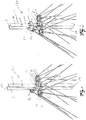
- Figure 1 shows a carrier unit 1 with two belt plates 10 a, b, which are connected to one another via a web 9.
- the carrier unit 1 has a pointed end 16 in order to facilitate the introduction of the carrier unit into the substrate 7.
- the belt plates have drilled holes 17 to which the retaining plates 8a and 8c can be mounted and screwed via a screw connection 15.
- the web 9 also has drilled holes to which the retaining plate 8b can be mounted and screwed.
- movable spherical bodies 18 are arranged in a through opening 38, which spherical bodies 18 receive a peg 5 with a thread.
- the spherical body 18 is held by an upper holding plate 19 which is screwed to the holding plate 8.
- the spherical body 18 has a holding stub 20 which has an internal thread, by means of which a rotary movement applied to the holding stub 20 can be transmitted to the external thread of the peg 5.
- the holding stub 20 has application surfaces distributed around the circumference for the application of a tool.
- Figure 2 shows a to Figure 1 modified example, a flange plate 23 being screwed to the carrier unit 1 above the retaining plates 8.
- the flange plate 23 consists of two semicircular pieces 23 a and 23 b, which are joined together during assembly on the carrier unit 1 and form a closed disk.
- the flange plate has a large number of boreholes 14 distributed on the edge, which are used to screw a pipe element that is placed on the flange plate and has a flange plate of the same type.
- the flange plate 23 itself is screwed to the carrier unit 1 via the screw connection 24.
- Figure 3 shows a representation of the components from which the post support assembly is assembled.
- the belt plate 10a is shown with the drill holes 17 for attaching the retaining plates 8a, c, as well as the web 9 of the carrier unit 1, which has the drill holes 48 for attaching the retaining plate 8b.
- the various components of the retaining plates and the flange plates are shown.
- the holding plate 8b has a straight extension 58b, on the upper side of which the corner connection 52 is welded standing in a later processing step, the other end of which is welded to the plate 51.
- one end of the corner connection 53 is welded to the underside of the projection 58b in an upright position, the other end of which is also welded to the plate 51.
- the corner connection 52, 53 thus form a diagonal connection between the holding plate 8, which are perpendicular to one another, and the plate 51.
- a corner connection 52 and a corner connection 54 which in turn are connected to a holding plate 51, are welded onto the holding plate 8a, c and their extension 58a, c.
- the flange plate 23, which is present with the two halves 23a and 23b, has two parallel slots per half.
- FIG. 4 shows modified embodiment of the support arrangement with two holding plates 8b which are attached to the front and rear of the web 9.
- the corner connections 54 are also shown, which run diagonally between the plate 51 arranged perpendicular to one another and the underside of the holding plate 8.
- Figure 5 shows the top view of the carrier unit 1 to which the retaining plates 8 are screwed and the upper retaining plates 19 are screwed onto the lower retaining plates 8, with which the spherical body 18 can be clamped on the retaining plate 8.
- FIG 6 shows the embodiment according to Figure 1 , wherein a mast 13 is additionally mounted on a carrier unit 1, whereby a post support structure is created.
- This mast 13 is solid and is screwed to the support unit 1 via the screw connection 25, the round mast being mounted between the two belts 10 a, b.
- the screw connection 25 is passed through a bent sheet metal 26 which, with its curved shape, rests on the outer circumference of the mast 13 and, after being screwed to the support unit 1, additionally stabilizes the mast.
- Figure 7 shows the embodiment according to Figure 2 , wherein a tubular element 12 has been placed on the carrier unit 1.
- the tube element 12 has a flange plate 27 on its underside, which is placed on the preassembled flange plate 23 of the carrier unit 1 and screwed to it via the screw connection 28.
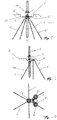
- Figure 8 shows the erection and fixing of the post support arrangement of the carrier unit 1 in the subsurface 7.
- a hole 59 is dug until a predetermined depth is reached.
- the support unit 1 is driven with the tip 16 first into the base 49 of the hole or into the underlying base 7, until the holding plates 8 mounted on the support unit 1 rest on the base 49.
- the desired depth for setting up the carrier unit 1 is thus achieved.
- the Ground nails 5 are driven through the ball joints 6 of the retaining plates 8 into the substrate 7 below the bottom 49 of the hole 59.
- the support unit 1 is thus fixed in the subsurface 7 by the pegs 5, the pegs providing the necessary stabilization.
- the hole 59 is then filled up again with pourable material up to the top surface 29, as shown in FIG Figure 9 you can see.
- Figure 9 shows the side view of Figure 8 in the buried state, the retaining plates 8 now being located below the top edge 29 of the ground in the subsurface 7.
- the holding plates 8 are arranged outside the central longitudinal axis of the carrier unit 1. Is also in Figure 9 It can be seen that the end 16 of the carrier unit 1 is sharpened in order to facilitate the introduction of the carrier unit 1 into the substrate 7.
- Figure 10 shows the top view of the carrier unit 1, which has the three retaining plates 8a, b and c, which extend perpendicularly, starting from the central longitudinal axis of the carrier unit 1, in three directions.
- the ball joints 6 for aligning the pegs are arranged, which are composed of the spherical body 18, the holding stub 20 and the upper holding plate 19 in connection with the screw connection 38 in the holding plate 8.
- Figure 11 shows the upper holding plate 19 and the lower holding plate 8 in a sectional view, the holding plate 19 having a passage opening 37 and the lower holding plate 8 having a passage opening 38.
- the passage opening 37 tapers towards the outside in the upper holding plate 19.
- the passage opening 38 of the holding plate 8 also tapers outwards, starting from the gap 39.
- the inner edges 41 of the access opening 37 of the upper holding plate 19 form an opening angle 43 to one another in the example shown here.
- the inner edges 42 of the access opening 38 of the lower holding plate 8 also form an opening angle 44 to one another.
- the inner edges 41, 42 can also be designed to be curved or have a different geometric shape.
- the gap 39 is also variable and can be made larger or smaller depending on the size of the spherical body 18.
- the two retaining plates 8, 19 are then held together by the screw connection 47, consisting of the screw 45 and the nut 46.
- Such a screw connection of the individual holding plates to one another serves to fix the spherical body 18 in a desired position inside the holding plates 8, 19.
- the spherical body 18 with its peg 5 can assume an angle deviating from the vertical direction in order to drive the peg obliquely into the ground or the ground 7.
- pegs 5 can thus be driven obliquely into the ground in a lower retaining plate 8 resting on the substrate 7, ie at an angle less than 90 ° with respect to the lower retaining plate 8.
- the spherical body 18 remains movable between the retaining plates 8, 19 until the peg 5 has assumed the correct angle and after the alignment of the spherical body and the insertion of the peg 5 into the ground, the spherical body 18 is between the two retaining plates via the screw connection 47 Clamped in a secured position so that this angle is permanently set.
- the screw connection 47 is released so that the spherical body 18 can be rotated again.
- a rotary movement is then exerted on the spherical body 18 with a tool via the holding connector 20 and the peg 5 is driven upwards out of the subsurface 7 or downwards into the subsoil, depending on the direction of rotation.
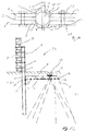
- Figure 12 shows a further embodiment of the present invention, wherein the inventive carrier unit 1 no longer has ear-shaped retaining plates 8, but at least one horizontally laid carrier unit 2.
- the carrier unit fulfills the function of the retaining plate, as is the case with the post support arrangement.
- this exemplary embodiment shows a wall support arrangement 50 as an example of a support arrangement using a decentralized holding position and support.
- the use of such carrier units 2 also enables the entire arrangement to be fixed and stabilized outside the central longitudinal axis of the carrier unit 1.
- the carrier unit 2 also has ball joints 6 with which the pegs 5 can be inserted into the ground 7 and secured in position.
- the carrier unit 2 and the further carrier units connected to it are also arranged below the top edge 29 of the terrain and form a flat foundation or an arrangement of pegs for a masonry support structure.
- the orientation of the carrier unit 32 is perpendicular to the longitudinal axis of the carrier unit 2 and serves to additionally absorb forces which are transmitted through the masonry via the carrier unit 1 to the carrier unit 2.
- the carrier unit 32 thus serves to provide additional support for the masonry 3.
- the carrier unit 1 rests on the masonry 3 and is connected to it via a screw connection 30.
- the carrier unit 2 is connected to the carrier unit 1 via a screw connection 60.
- a corner connection 31 is also arranged in the connection area between the carrier unit 1 and the carrier unit 2 and is screwed to the carrier unit 1 via the screw connection 61.
- the carrier units can also be welded to one another and the corner connection to the carrier units
- the carrier unit 2 and 32 are designed as a double-T carrier, the ball joints 18 being located in corresponding pass-through openings in the belt 34 of the carrier unit 2 and in the belt 33 of the carrier unit 32.
- the support units 2 and 32 thus form, together with the ball joint 6 and the peg 5, the underground peg arrangement.
- Figure 13 shows the top view of Figure 12 with the carrier unit 1, which is connected to the masonry 3 via the screw connection 30 and supports it.
- the carrier unit 2 is screwed to the carrier unit 1 via the screw connection 8.
- the upper straps 33a, 34a of the support units 2, 32 are shown as transparent in order to better recognize the ball joints 6 located below.
- the carrier unit 2 has a number of ball joints 6 which are arranged parallel to one another and which the carrier unit 32 running perpendicular to the carrier unit 2 also has.
- the carrier unit 2 and the carrier unit 32 thus form a cross and are screwed to one another at the crossing point.
- Figure 14 shows a top view of the carrier units 2, 32 wherein the belt 34a of the carrier unit 2 can be seen, which is narrower than the belt 34b of the carrier unit 2.
- the narrower belt provides access to the ball joints 6 connected to the belt 34b from above possible.
- the carrier unit 32 has the belt 33a, which is also narrower compared to the Belt 33b is formed.
- FIG. 4 shows the front view of the carrier arrangement according to FIG Figure 12 .
- Figure 16 shows the screw connection of the carrier unit 2 to the carrier unit 32 in an enlarged view, it being evident that the belt 33a of the carrier unit 32 is narrower than the belt 33b.
- the alignment of the edges of the straps 33 a, b form a line 35 which is formed at an angle with respect to the corner connection 36 of the carrier unit 32. This is intended to make it clear that, due to the narrower belt 33 a, access to the ball joint 6 is possible, which is located on or in the belt 33 b.
Landscapes
- Engineering & Computer Science (AREA)
- Structural Engineering (AREA)
- Civil Engineering (AREA)
- Architecture (AREA)
- Life Sciences & Earth Sciences (AREA)
- General Life Sciences & Earth Sciences (AREA)
- Mining & Mineral Resources (AREA)
- Paleontology (AREA)
- General Engineering & Computer Science (AREA)
- Piles And Underground Anchors (AREA)
- Bridges Or Land Bridges (AREA)
Abstract
Pfostenstützanordnung (40) zur Aufnahme und Stützung eines Pfostens (12, 13) zur Verankerung in einem Untergrund (7) umfassend:- eine Pfostenstützstruktur, die in den Untergrund (7) eingebracht und dazu angepasst ist, das untere Ende des Pfostens (12, 13) aufzunehmen,- eine unterirdische Erdnagelanordnung, die mit der Pfostenstützstruktur verbunden ist, bestehend aus mindestens zwei voneinander beabstandeten Tragarmen (8a, b, c), die mit der Erdnagelanordnung verbunden sind und sich im Winkel zur Achse des Pfostens (12, 13) erstrecken, wobei im Tragarm mindestens eine Durchgriffsöffnung für mindestens einen Erdnagel (5) angeordnet ist, der durch die Durchgriffsöffnung hindurch in einem Winkel zur Achse des Tragarms (8a, b, c) in den Untergrund (7) getrieben ist, wobei der Tragarm (8a, b, c) als flächige Halteplatte (8a, b, c) ausgebildet ist, die mehrere Durchgriffsöffnungen (38) aufweist, in denen jeweils ein beweglicher Kugelkörper (18) angeordnet ist, durch den der Erdnagel (5) hindurchgeführt ist und dass der Kugelkörper zwischen einer oberen Halteplatte (19) und der unteren flächigen Halteplatte (8) lagengesichert eingespannt ist.Post support arrangement (40) for receiving and supporting a post (12, 13) for anchoring in a ground (7) comprising: - a post support structure which is introduced into the ground (7) and is adapted to support the lower end of the post (12, 13), - an underground peg arrangement which is connected to the post support structure, consisting of at least two spaced-apart support arms (8a, b, c) which are connected to the peg arrangement and are at an angle to the axis of the post (12, 13) extend, wherein in the support arm at least one penetration opening for at least one peg (5) is arranged, which is driven through the penetration opening at an angle to the axis of the support arm (8a, b, c) into the ground (7), the support arm ( 8a, b, c) is designed as a flat holding plate (8a, b, c), which has several penetration openings (38), in each of which a movable spherical body (18) is arranged, through which the peg (5) hinders is carried out and that the spherical body is clamped in a secured position between an upper holding plate (19) and the lower flat holding plate (8).
Description
Gegenstand der Erfindung ist eine Stützanordnung zur Aufnahme und Stützung von Pfosten, technischen Bau- und Mauerwerken nach den Oberbegriffen der Ansprüche 1 und 7.The subject of the invention is a support arrangement for receiving and supporting posts, technical structures and masonry according to the preambles of
Unter einem Pfosten wird in der vorliegenden Anmeldung entweder ein längliches, vertikal in Gebäuden verbautes Tragelement oder ein freistehendes, mit dem Untergrund verbundenes längliches, vertikales Bauelement bezeichnet.In the present application, a post is used to denote either an elongated support element installed vertically in buildings or a free-standing elongated, vertical structural element connected to the subsurface.
Unter einer Pfostenstützanordnung wird in der vorliegenden Anmeldung eine Vorrichtung zur Befestigung und Abstützung eines Aufbaus, insbesondere eines stab-, pfosten- oder rohrförmigen Gegenstands verstanden.In the present application, a post support arrangement is understood to mean a device for fastening and supporting a structure, in particular a rod-shaped, post-shaped or tubular object.
Ein Mauerwerk ist ein aus natürlichen oder künstlichen Steinen gefügtes Bauteil oder Bauwerk als Massivbau. Das Mauerwerk besteht aus einzelnen druckfesten Elementen (Natursteine oder künstliche Steine, wie beispielsweise Lehmziegel, Mauerziegel oder Hohlblocksteine).Masonry is a component or structure made of natural or artificial stones as a solid structure. The masonry consists of individual pressure-resistant elements (natural stones or artificial stones such as clay bricks, masonry bricks or hollow blocks).
Unter einer Mauerstützanordnung wird in der vorliegenden Anmeldung eine Vorrichtung zur Befestigung und Abstützung einer Mauer, insbesondere einer flachen, vertikal verlaufenden Wand verstanden.In the present application, a wall support arrangement is understood to mean a device for fastening and supporting a wall, in particular a flat, vertically extending wall.
Für die fest Einbringung einer derartigen Stützanordnung wird bevorzugt ein Erdnagel in den Untergrund eingebracht. Unter einem Erdnagel ist vorzugsweise ein runder Metallstab zu verstehen, dessen Außenmantel über die gesamte Länge seines Verlaufes mit einem Gewindeprofil versehen ist.For the permanent installation of such a support arrangement, a peg is preferably inserted into the ground. A peg is preferably to be understood as a round metal rod, the outer jacket of which is provided with a thread profile over the entire length of its course.
Derartige Erdnägel können, unabhängig von ihrer Materialbeschaffenheit, nicht nur auf der Grundlage eines Rundstabes aufgebaut sein, sondern in ihrem Querschnitt auch kantig oder oval ausgebildet sein, oder neben einer durchgehend glatten Oberfläche auch eine Verbindung mehrerer Profilierungen aufweisen.Such pegs can, regardless of their material properties, not only be built on the basis of a round rod, but also have an angular or oval cross-section or, in addition to a continuously smooth surface, also have a connection of several profiles.
Erdnägel können aufgrund ihres Gewindeverlaufes (vergleichbar mit einem Bohrgewinde) zum bohrähnlichen Durchdringen von Materialien verwendet werden, die entsprechend ihrer Morphologie das Eindringen eines solchen Nagels zulassen.Because of their thread course (comparable to a drill thread), ground nails can be used for drilling-like penetration of materials which, according to their morphology, allow the penetration of such a nail.
Damit können Erdnägel z.B. in Materialschichtungen aus Sand, Geröll, Schnee, Eis, Schotter, Gestein oder deren Vermengungen untereinander eingetrieben werden.This means that pegs can be driven into layers of material made of sand, rubble, snow, ice, gravel, stone or their mixtures with one another.
Als Idealfall wird eine Grundierung angesehen, die z.B. aus Schnee, Eis, Sand, Erde oder Lehm besteht, wobei ein Erdnagel beim Eindrehen der Zugrichtung seines Gewindeprofils folgt und schlüssig in der Grundierung den gewünschten Halt findet.The ideal case is a primer made of e.g. snow, ice, sand, earth or clay, whereby a peg follows the pulling direction of its thread profile when it is screwed in and finds the desired hold in the primer.
Die Einbringung des Erdnagel in den Untergrund richtet sich nach der morphologischen Beschaffenheit des Untergrunds und kann wahlweise durch eine Vorbohrung in der vorgesehenen Tiefe und Neigung erfolgen. Dies ist auch ohne Vorbohrung möglich, indem das Außengewinde des Erdnagels die Funktion eines Bohrgewindes übernimmt und sich so unter vertikalem Druck oder Zug in den Untergrund einarbeitet oder daraus löst.The insertion of the peg into the subsoil depends on the morphological nature of the subsoil and can optionally be carried out by pre-drilling in the intended depth and inclination. This is also possible without pre-drilling, in that the external thread of the peg takes on the function of a drill thread and works into or loosens from the ground under vertical pressure or tension.
Die Standfestigkeit eines Mauerwerkes oder einer allgemeinen bautechnischen Vorrichtung zeichnet sich durch die Statik, wie aber auch durch die Fundamentierung desselben aus. Wird eine dieser Komponenten bei Planung oder Erstellung der Baumaßnahme vernachlässigt, ist der sichere Erhalt und damit die Funktion der gesamten Baumaßnahme nicht mehr gewährleistet.The stability of a masonry or a general structural device is characterized by the statics, but also by the foundation of the same. If one of these components is neglected during the planning or creation of the construction project, the safe maintenance and thus the function of the entire construction project is no longer guaranteed.
Auch nach der Fertigstellung eines Mauerwerkes oder einer bautechnischen Vorrichtung kann durch äußere Einwirkungen die ursprüngliche Funktion abgeschwächt oder aufgehoben werden. So können schleichend oder auch sprunghaft einsetzende Veränderungen der Bausubstanz das betroffene Gewerk früher oder später in seiner Funktion beinträchtigen und führen somit zu einem hohen Sicherheitsrisiko.
Reparaturarbeiten, soweit sie überhaupt noch möglich sind, können in derartigen Fällen nur dadurch erreicht werden, dass Teilstrukturen des Mauerwerkes oder der zentralen Fundamentierung entfernt und mit großem Aufwand erneuert werden.Even after the completion of a masonry or a structural device, the original function can be weakened or canceled by external influences. Gradual or sudden changes in the building fabric can, sooner or later, impair the function of the affected trade and thus lead to a high security risk.
Repair work, insofar as it is still possible at all, can only be achieved in such cases by removing partial structures of the masonry or the central foundation and replacing them with great effort.
Derartig aufwendige Reparaturarbeiten sind im Vergleich zu einer generellen Neuerrichtung unwirtschaftlich und können für die Dauer ihrer Ausführung die dem Mauerwerk ursprünglich zugedachten Funktionen wesentlich beeinträchtigen.Such complex repair work is uneconomical in comparison to a general new construction and can significantly impair the functions originally intended for the masonry for the duration of its execution.
Nicht selten sind derartige Hilfsmaßnahmen nur von kurzem Erfolg und das in seiner Substanz geschwächte Mauerwerk muss früher oder später zur Gänze abgetragen und in der Folge wieder vollkommen neu errichtet werden.It is not uncommon for such aid measures to be only of short success and the masonry, which has weakened in its substance, sooner or later has to be completely removed and then completely rebuilt.
Für derartige bautechnische Reparaturmaßnahmen in dieser Größenordnung ist in den meisten Fällen die Einbeziehung einer bereits bestehenden Fundamentierung notwendig. Kann diese nicht mehr in Anspruch genommen werden oder muss partiell ausgetauscht werden, muss auf herkömmliche Bodenanker zurückgegriffen werden, die als Erdschraube oder Einschlagelement in der Lage sind, den Druck von Lasten in sich zentral aufzunehmen und in einem engen Einzugsbereich zu verankern.For such structural repair measures of this magnitude, the inclusion of an already existing foundation is necessary in most cases. If this can no longer be used or if it has to be partially replaced, conventional ground anchors must be used, which, as earth screws or impact elements, are able to centrally absorb the pressure of loads and anchor them in a narrow catchment area.
Gleichzeitig kann eine solche Montage nur ausgeführt werden, wenn über dem einzusetzenden Erdnagel ein derart vertikaler Freiraum besteht oder geöffnet werden kann, damit ein solcher Schraub- oder Schlagnagel mit hydraulischem oder ähnlichem Gerät eingedreht oder eingeschlagen werden kann. Nur in seltenen Fällen sind derartige Rahmenbedingungen gegeben.At the same time, such an assembly can only be carried out if there is a vertical free space above the peg to be inserted or can be opened so that such a screw or hammer nail can be screwed in or hammered in with a hydraulic or similar device. Such framework conditions are only given in rare cases.
Die Verwendung von Erdnägeln für eine Stützanordnung ist auch zur Versteifung von Holzkonstruktionen, Holzpfählen, Freileitungsmasten und dergleichen bekannt, die infolge von Witterungseinflüssen schadhaft geworden sind. Hierfür wird in einer Grube neben dem schadhaften Mast ein Betonkörper eingesetzt, der an seinem oberen Ende eine metallene Tragkonstruktion aufweist, welche mit dem Mast verschraubt wird. Anschließend wird der schadhafte Teil des Mastes unterhalb des Befestigungspunktes herausgesägt, sodass der Mast nunmehr mit den Eisenstreben des Betonkörpers gestützt wird.The use of pegs for a support arrangement is also known for stiffening wooden structures, wooden piles, overhead line masts and the like, which have become damaged as a result of the weather. For this purpose, a concrete body is used in a pit next to the defective mast, which has a metal support structure at its upper end, which is screwed to the mast. The damaged part of the mast is then sawn out below the fastening point so that the mast is now supported with the iron struts of the concrete body.
Für die Stabilisierung von Pfosten, wie zum Beispiel Zaunpfählen, werden ebenfalls Erdnägel verwendet, wie es beispielsweise mit der Stützanordnung der
So zeigt auch die
- eine Pfostenstützstruktur, die in den Untergrund eingebracht und dazu angepasst ist, das untere Ende des Pfostens aufzunehmen,
- eine unterirdische Anordnung von Erdnägeln, die mit der Pfostenstützstruktur verbunden ist und aus drei voneinander beabstandeten Tragarmen besteht, die mit der Anordnung von Erdnägeln verbunden sind und sich im Winkel zur Achse des Pfostens erstrecken. Dabei ist im Tragarm mindestens eine Durchgriffsöffnung für mindestens einen Erdnagel angeordnet, der durch die Durchgriffsöffnung hindurch in einem Winkel zur Achse des Tragarms in den Untergrund getrieben werden kann.
- a post support structure that is sunk into the ground and adapted to receive the lower end of the post,
- an underground peg assembly connected to the post support structure and consisting of three spaced apart support arms connected to the peg assembly and extending at an angle to the axis of the post. At least one penetration opening for at least one peg is arranged in the support arm, which can be driven into the ground through the penetration opening at an angle to the axis of the support arm.
Hierbei verfügt der Pfosten über eine Art Manschette, an der die Aufnahmearme flügelartig angeschweißt sind. Gegenüber der bereits genannten
Bei diesen bekannten Fundamentierungen besteht jedoch der Nachteil, dass diese nur in unmittelbarer Nähe des Pfostens, d.h. nahe der Mittenlängsachse in den Untergrund eingebracht werden können. So kann keine ausreichende Stabilisierung garantiert werden, wenn sehr große Kräfte, wie z.B. verursacht durch Wind, auf den Pfosten wirken und welche von den von dem Pfosten abzweigenden Erdnägeln nur ungenügend aufgenommen werden können und der Pfosten umkippen kann.With these known foundations, however, there is the disadvantage that they can only be introduced into the ground in the immediate vicinity of the post, ie near the central longitudinal axis. Sufficient stabilization cannot be guaranteed if very large forces, such as those caused by wind, act on the post and which can only be insufficiently absorbed by the pegs branching off the post and the post can tip over.
Der vorliegenden Erfindung liegt somit die Aufgabe zu Grunde, eine Stützanordnung zur Aufnahme und Stützung von Pfosten und Mauerwerk so auszugestalten, dass eine einfach in den Untergrund einzubringende und gemäß den erwartenden Kräften dimensionierende Fundamentierung gegeben ist.The present invention is therefore based on the object of designing a support arrangement for receiving and supporting posts and masonry in such a way that there is a foundation that is easy to introduce into the subsurface and dimensioned according to the expected forces.
Die Aufgabe wird erfindungsgemäß durch die Merkmale der unabhängigen Patentansprüche 1 und 7 gelöst, während vorteilhafte Ausgestaltungen und Weiterbildungen der Erfindung den Unteransprüchen entnommen werden können.The object is achieved according to the invention by the features of the
Vorteilhaftes Merkmal ist, dass der von der Stützanordnung abstehende Tragarm als flächige Halteplatte ausgebildet ist, die mehrere Durchgriffsöffnungen aufweist, in denen jeweils ein beweglicher Kugelkörper angeordnet ist, durch den ein Erdnagel hindurchgeführt ist und dass der Kugelkörper zwischen einer oberen Halteplatte und der unteren flächigen Halteplatte lagengesichert eingespannt ist.An advantageous feature is that the support arm protruding from the support arrangement is designed as a flat holding plate which has several penetration openings in each of which a movable spherical body is arranged through which a peg is passed and that the spherical body is between an upper holding plate and the lower flat holding plate is clamped in a secured position.
Die erfindungsgemäße Anordnung dient somit als dezentrales Fundamentierungs-und Sicherungssystem, welches in beliebig seitlicher Positionierung zu einem Pfosten oder einem Mauerwerk den sogenannten Schweredruck in sich aufnehmen kann und diesen mit beliebigem Richtungsverlauf und Abstand in einfacher Weise oder über mehrere vertikale Ebenen seitlich ableiten kann.
Somit ist eine vollkommen neue und gleichzeitig entlastende Fundamentierung möglich. Horizontallasten können über durch die Halteplatte geführte, in den Untergrund eingebrachte Erdnägel in den Untergrund abgetragen werdenThe arrangement according to the invention thus serves as a decentralized foundation and securing system, which can absorb the so-called gravity pressure in any lateral positioning to a post or masonry and can derive it laterally with any direction and distance in a simple manner or over several vertical planes.
Thus, a completely new and at the same time relieving foundation is possible. Horizontal loads can be transferred into the subsoil by means of pegs that are guided through the retaining plate and inserted into the subsoil
Durch die Verwendung von Halteplatten, welche außerhalb der Längsachse der Pfostenstützstruktur angeordnet sind, oder von horizontalen Trägereinheiten, welche außerhalb der Längsachse der Mauerwerkstützstruktur angeordnet sind, wird die wirkende Kraft flächig verteilt. Die erfindungsgemäße Stützanordnung ist insbesondere zur Abtragung großer Lasten geeignet.Through the use of holding plates which are arranged outside the longitudinal axis of the post support structure, or of horizontal support units which are arranged outside the longitudinal axis of the masonry support structure, the acting force is distributed over a large area. The support arrangement according to the invention is particularly suitable for transferring large loads.
So weist auch die obere Halteplatte, welche mit der unteren Halteplatte verschraubt ist, eine Durchgriffsöffnung auf, durch welche der Kugelkörper teilweise herausragt. Der Kugelkörper weist einen Haltestutzen mit einem Innengewinde auf, durch das eine auf den Haltestutzen aufgebrachte Drehbewegung auf das Gewinde des Erdnagels übertragbar ist.The upper holding plate, which is screwed to the lower holding plate, also has an opening through which the spherical body partially protrudes. The spherical body has a holding stub with an internal thread through which a rotational movement applied to the holding connector can be transmitted to the thread of the peg.
Die Pfostenstützstruktur besteht somit aus einer vertikal in den Untergrund eingebrachten Trägereinheit, an der seitlich mindestens zwei Halteplatten montiert sind.The post support structure thus consists of a carrier unit which is vertically inserted into the subsurface and on which at least two retaining plates are mounted on the sides.
Bevorzugt werden Stahlträger aus wetterfestem Baustahl (z.B. Cortenstahl) für die Stützanordnung als Trägereinheit verwendet. Stahlträger sind dabei entweder gewalzte oder geschweißte Profile, die in verschiedenen Maßen und Ausführungen erhältlich sind. Es handelt sich hierbei um tragende Bauteile, die aufgrund ihrer Beschaffenheit besonders robust sind, eine hohe Belastbarkeit und Tragkraft aufweisen und flexibel einsetzbar sind. Bevorzugt werden sogenannte Doppel-T-Träger verwendet, welche über einen Oberflansch verfügen und einen über einen Steg damit verbundenen Unterflansch. Hierauf ist die Erfindung jedoch nicht beschränkt. So können in einer weiteren Ausführungsform der Erfindung auch Träger verwendet werden, welche z.B. über ein U-Profil verfügen.Steel girders made of weatherproof structural steel (e.g. Corten steel) are preferably used for the support arrangement as a carrier unit. Steel girders are either rolled or welded profiles that are available in various sizes and designs. These are load-bearing components that are particularly robust due to their nature, have a high load-bearing capacity and load-bearing capacity and can be used flexibly. So-called double-T beams are preferably used, which have an upper flange and a lower flange connected to it via a web. However, the invention is not restricted to this. Thus, in a further embodiment of the invention, supports can also be used which, for example, have a U-profile.
In der vorliegenden Erfindung werden diese Flansche allgemein als Gurte bezeichnet, wobei als Gurte im Beton-, Holz- und Stahlbau die oberen und unteren Bänder eines Trägers mit Doppel-T-förmigem Querschnitt bezeichnet werden, die von dem durchgehenden Steg auf Abstand gehalten werden. Diese Gurte nehmen vor allem die Belastung aus Biegung auf.In the present invention, these flanges are generally referred to as belts, the upper and lower belts of a beam with a double-T-shaped cross-section, which are held at a distance from the continuous web, are referred to as belts in concrete, wood and steel construction. Above all, these belts absorb the load from bending.
An einem solchen vertikalen Träger, der den Grundbestandteil der erfindungsgemäßen Pfostenstützstruktur darstellt, lassen sich nun in beliebiger Anzahl die Halteplatten seitlich befestigen, die in sich eine beliebige Anzahl von Öffnungen aufweisen, durch die die Erdnägel (bevorzugt aus Stahl) in Form von glatten Rundstäben oder Gewindestäben in beliebiger Ausrichtung, mittels einfacher Eindreh- oder Schlagwerkzeuge eingebracht und schraub- oder schweißtechnisch fest verbunden werden können. So kommt es, zusätzlich zur flächigen Auflage der Halteplatten auf dem Untergrund zu einer zusätzlichen Stabilisierung im Erdreich durch die Einbringung der Erdnägel in den Untergrund.On such a vertical support, which is the basic component of the post support structure according to the invention, the retaining plates can now be attached laterally in any number, which have any number of openings through which the pegs (preferably made of steel) in the form of smooth round rods or Threaded rods can be inserted in any orientation using simple screwing or striking tools and can be firmly connected by screwing or welding. Thus, in addition to the flat support of the retaining plates on the ground, there is additional stabilization in the ground through the introduction of the pegs into the ground.
Mit dem zu sichernden Pfosten fest verbunden ist nun eine hochwirksame, in sich variable Fundamentierung entstanden, die den Schweredruck des Pfostens seitlich ableitet, damit die Gesamtstatik desselben entlastet wird und die Abstützung der Halteplatten im Erdreich sich auf den Pfosten überträgt und diesen damit stabilisiert.Firmly connected to the post to be secured, a highly effective, inherently variable foundation has been created, which dissipates the gravitational pressure of the post to the side so that the overall statics of the post is relieved and the support of the retaining plates in the ground is transferred to the post and thus stabilized.
Die ausgehend von der Längsachse der Trägereinheit senkrecht montierten Halteplatten weisen eine Eckverbindung als zur Versteifung des Eckbereichs an der Kontaktstelle von Träger und Halteplatte auf. Diese Eckverbindung dient zur Einleitung und Verteilung von eingebrachten Lasten, zur Erhöhung der Ecksteifigkeit, zur Herstellung einer biegesteifen Ecke und ist im Stahlbau unter der Bezeichnung Vouten bekannt.The holding plates, which are mounted vertically starting from the longitudinal axis of the carrier unit, have a corner connection as a means of stiffening the corner area at the contact point between the carrier and the holding plate. This corner connection is used to introduce and distribute introduced loads, to increase the corner stiffness, to produce a rigid corner and is known in steel construction under the name Vouten.
Somit kann der Kraftfluss gleichmäßig verteilt werden und die Biegespannungen sinken, was wichtig ist für Dimensionierung der Schweißnähte und für den Schubfluss im Stegblech der Trägereinheit.Thus, the power flow can be evenly distributed and the bending stresses decrease, which is important for dimensioning the weld seams and for the shear flow in the web plate of the carrier unit.
In einer weiteren Ausführungsform der Erfindung ist an dem Abschnitt der Trägereinheit, der oberirdisch aus der Geländeoberkante ragt, eine die Trägereinheit umschließende Flanschplatte zur Aufnahme ebenfalls einen Flansch aufweisenden Rohrelements, montiert.In a further embodiment of the invention, on the section of the carrier unit which protrudes above ground from the top edge of the terrain, a flange plate enclosing the carrier unit for receiving a pipe element likewise having a flange is mounted.
In einer zweiten Ausführung der Erfindung kann mit der Stützanordnung auch ein Mauerwerk abgestützt werden. Um das zu erreichen wird mindestens eine vertikale Trägereinheit (bevorzugt aus Stahl) an dem zu stützenden Mauerwerk als Grundhalterung angedockt, d.h. fest verbunden. Der vertikale Träger wird dafür entweder über der Erdoberfläche oder teilweise im Untergrund positioniert, wobei eine teilweise im Untergrund eingebrachte Trägereinheit bereits unter der einbezogenen Erdoberfläche eine wichtige Fundamentierungsfunktion übernehmen kann.In a second embodiment of the invention, masonry can also be supported with the support arrangement. To achieve this, at least one vertical support unit (preferably made of steel) is docked to the masonry to be supported as a basic bracket, i.e. firmly connected. For this purpose, the vertical support is positioned either above the surface of the earth or partially in the subsurface, whereby a support unit, which is partially installed in the subsurface, can already take on an important foundation function under the included surface of the earth.
So zeichnet sich die erfindungsgemäße Mauerstützanordnung zur erdgestützten Abstützung eines mindestens teilweise oberirdisch angeordneten Mauerwerks, dadurch aus, dass
- der untere Teil einer Mauerwerkstützanordnung in den Untergrund eingebracht ist und der obere Teil mit dem zu stützenden Mauerwerk verbunden ist,
- eine unterirdische Erdnagelanordnung zur stabilen Fixierung der Mauerwerkstützstruktur im Untergrund vorhanden ist, bestehend aus mindestens einem Tragarm, der sich senkrecht zur vertikalen Achse des Mauerwerks erstreckt, in dem mindestens eine Durchgriffsöffnung für mindestens einen Erdnagel angeordnet ist, der durch die Durchgriffsöffnung hindurch in einem Winkel zur Achse des Tragarms in den Untergrund getrieben ist.
- the lower part of a masonry support arrangement is inserted into the ground and the upper part is connected to the masonry to be supported,
- an underground peg arrangement for stable fixation of the masonry support structure in the subsurface is present, consisting of at least one support arm which extends perpendicular to the vertical axis of the masonry, in which at least one penetration opening for at least one peg is arranged, which through the penetration opening at an angle to Axis of the support arm is driven into the ground.
Die Mauerstützanordnung zeichnet sich zudem dadurch aus, dass
der mindestens eine Tragarm als profilierte Halteplatte ausgebildet ist, welche über mehrere Durchgriffsöffnungen verfügt, in denen jeweils ein beweglicher Kugelkörper angeordnet ist, durch den der jeweilige Erdnagel hindurchgeführt ist und dass der Kugelkörper zwischen einer oberen Halteplatte und der unteren flächigen Halteplatte lagengesichert eingespannt ist.The wall support arrangement is also characterized in that
the at least one support arm is designed as a profiled holding plate, which has several penetration openings, in each of which a movable spherical body is arranged, through which the respective peg is passed and that the spherical body is clamped in a secured position between an upper holding plate and the lower flat holding plate.
Die Mauerstützanordnung zeichnet sich zudem dadurch aus, dass die Mauerwerkstützstruktur aus einer vertikal in den Untergrund eingebrachten Trägereinheit besteht, an der seitlich mindestens eine weitere Trägereinheit montiert ist und dass zur Versteifung des Eckbereichs zwischen der Trägereinheit und der mindestens einen weiteren Trägereinheit, eine Eckverbindung montiert ist, welche die Trägereinheit und Trägereinheit diagonal verbindet.The wall support arrangement is also characterized in that the masonry support structure consists of a carrier unit that is vertically inserted into the ground, on which at least one further carrier unit is mounted on the side and that a corner connection is mounted to stiffen the corner area between the carrier unit and the at least one further carrier unit , which connects the carrier unit and carrier unit diagonally.
Die Mauerstützanordnung zeichnet sich zudem dadurch aus, dass weitere Trägereinheiten über eine Schraubverbindung miteinander verbunden sind, welche in einem Abstand zur vertikalen Trägereinheit verbaut sind.The wall support arrangement is also characterized in that further carrier units are connected to one another via a screw connection, which are installed at a distance from the vertical carrier unit.
Ausgehend von dieser vertikalen Trägereinheit können nun bevorzugt horizontal sowie auch in einem beliebigen Anstellwinkel an der vertikalen Trägereinheit, seitliche Trägereinheiten in beliebiger Anzahl und beliebiger Höhe montiert werden. Für eine solche Kombination einer ersten Trägereinheit und mindestens einer weiteren Trägereinheit (Neben-Träger), kann die mindestens eine weitere Trägereinheit auf dem ersten Träger aufgelegt oder ebenengleich mit diesem verbunden werden.Starting from this vertical support unit, lateral support units can now be mounted in any number and at any height, preferably horizontally and also at any angle of incidence on the vertical support unit. For such a combination of a first carrier unit and at least one further carrier unit (secondary carrier), the at least one further carrier unit can be placed on the first carrier or connected to it at the same level.
Zusätzlich kann eine diagonale Versteifung (Eckverbindung) zwischen den vertikalen und horizontalen Trägern verbaut werden, welche für eine größtmögliche Winkelstabilität sorgt.In addition, a diagonal reinforcement (corner connection) can be installed between the vertical and horizontal beams, which ensures the greatest possible angular stability.
So ist es in einer Weiterführung der Erfindung jederzeit möglich die horizontale Trägereinheit mit weiteren Zusatzträgern, sowohl in vertikaler als auch horizontaler Ebene zu ergänzen und damit eine Art Gitterstruktur zu schaffen. Die Zusatzträger weisen eine beliebige Anzahl von Durchgriffsöffnungen auf, durch die die Erdnägel in beliebiger Ausrichtung, mittels einfacher Eindreh- oder Schlagwerkzeuge, eingebracht und schraub- oder schweißtechnisch fest verbunden werden können. Somit wird eine mit dem zu sichernden Mauerwerk fest verbundene, hochwirksame und in sich variable Fundamentierung geschaffen, die den Schweredruck des einbezogenen Mauerwerkes seitlich ableiten kann, damit die Gesamtstatik desselben entlastet wird und die durchgehend stabile Gitterstruktur sich auf das Mauerwerk überträgt und stabilisiert.Thus, in a further development of the invention, it is possible at any time to supplement the horizontal support unit with further additional supports, both in the vertical and in the horizontal plane, and thus to create a type of lattice structure. The additional carriers have any number of penetration openings through which the pegs can be inserted in any orientation, using simple screwing or striking tools, and firmly connected by screwing or welding. This creates a highly effective and inherently variable foundation that is firmly connected to the masonry to be secured, which can divert the gravitational pressure of the masonry involved laterally, so that the overall statics of the masonry is relieved and the continuously stable lattice structure is transferred to the masonry and stabilized.
So kommt es, zusätzlich zur flächigen Auflage der vertikalen Trägereinheiten auf dem Untergrund, zu einer zusätzlichen Stabilisierung durch die Fixierung der Erdnägel im Untergrund. Damit kann die an einem Bauwerk auftretende Belastung in den Untergrund abgeleitet werden. Die Dimensionierung einer solchen Fundamentierung hängt vom Betrag der Lasten (z.B. Eigengewicht, Wind-, Schneelasten) sowie von der Struktur des Tragwerks und der Tragfähigkeit des Untergrundes ab. Somit können Normal- und Querkräfte sowie zusätzliche Momente in die Fundamente eingeleitet werden. Durch eine Schraub- und / oder Schweißverbindung entstehen mehr oder weniger steife Verbindungen zwischen den einzelnen Bauteilen.In addition to the flat support of the vertical support units on the ground, there is additional stabilization by fixing the pegs in the ground. In this way, the load that occurs on a building can be diverted into the subsoil. The dimensioning of such a foundation depends on the amount of loads (e.g. dead weight, wind and snow loads) as well as on the structure of the supporting structure and the load-bearing capacity of the subsoil. Thus normal and lateral forces as well as additional moments can be introduced into the foundations. A screw and / or weld connection creates more or less rigid connections between the individual components.
Bevorzugt wird zwischen der vertikalen Trägereinheit und der daran befestigten horizontalen Trägereinheit eine Eckverbindung montiert, die zur Einleitung und Verteilung von eingebrachten Lasten, zur Erhöhung der Ecksteifigkeit und zur Herstellung einer biegesteifen Ecke dient. Eine solche Eckverbindung ist im Stahlbau auch unter der Bezeichnung Voute bekannt und dient bei der erfindungsgemäßen Fundamentierung zur Vergrößerung des Kraftumlenkbereiches um die Biegesteifheit der Rahmenecke, der miteinander verbundenen Trägereinheiten, zu gewährleisten.A corner connection is preferably mounted between the vertical carrier unit and the horizontal carrier unit attached to it, which serves to introduce and distribute introduced loads, to increase the corner stiffness and to produce a rigid corner. Such a corner connection is also known in steel construction under the designation haunch and is used in the foundation according to the invention to enlarge the Kraftumlenkbereiches to ensure the rigidity of the frame corner, the interconnected support units.
Die für ein solches dezentrales Fundamentierungs- und Sicherungssystem notwendigen Komponenten sind, im Vergleich zu anderen bautechnischen Verfahren, bei hoher Wirtschaftlichkeit, einfach zu handhaben.
Werden die vertikalen wie auch horizontalen Trägereinheiten plan oder nur teilweise sichtbar unter der Außenwandung der bautechnischen Vorrichtung oder der Erdoberfläche angelegt, kann eine solche nachträglich eingebrachte Sicherungsmaßnahme von Außenstehenden kaum mehr wahrgenommen werden.The components required for such a decentralized foundation and securing system are easy to handle, compared to other structural engineering methods, with high economic efficiency.
If the vertical as well as horizontal support units are laid flat or only partially visible under the outer wall of the structural engineering device or the surface of the earth, such a subsequently introduced security measure can hardly be noticed by outsiders.
Es versteht sich von selbst, dass ein solches System nicht nur als Reparaturverfahren, sondern bei geprüfter Statik auch bei der Ersterrichtung eines technischen Mauerwerkes eingesetzt werden kann.It goes without saying that such a system can be used not only as a repair process, but also for the initial construction of technical masonry if the statics have been checked.
Der Erfindungsgegenstand der vorliegenden Erfindung ergibt sich nicht nur aus dem Gegenstand der einzelnen Patentansprüche, sondern auch aus der Kombination der einzelnen Patentansprüche untereinander.The subject matter of the present invention results not only from the subject matter of the individual patent claims, but also from the combination of the individual patent claims with one another.
Alle in den Unterlagen, einschließlich der Zusammenfassung offenbarten Angaben und Merkmale, insbesondere die in den Zeichnungen dargestellte räumliche Ausbildung, könnten als erfindungswesentlich beansprucht werden, soweit sie einzeln oder in Kombination gegenüber dem Stand der Technik neu sind. Die Verwendung der Begriffe "wesentlich" oder "erfindungsgemäß" oder "erfindungswesentlich" ist subjektiv und impliziert nicht, dass die so benannten Merkmale zwangsläufig Bestandteil eines oder mehrerer Patentansprüche sein müssen.
Im Folgenden wird die Erfindung anhand von mehrere Ausführungswege darstellenden Zeichnungen näher erläutert. Hierbei gehen aus den Zeichnungen und ihrer Beschreibung weitere erfindungswesentliche Merkmale und Vorteile der Erfindung hervor.All information and features disclosed in the documents, including the summary, in particular the spatial configuration shown in the drawings, could be claimed as being essential to the invention, insofar as they are new, individually or in combination, compared to the state of the art. The use of the terms “essential” or “according to the invention” or “essential to the invention” is subjective and does not imply that the features named in this way must necessarily be part of one or more patent claims.
In the following, the invention is explained in more detail with reference to drawings showing several possible embodiments. Further features and advantages of the invention that are essential to the invention emerge from the drawings and their description.
Es zeigen:
-
Figur 1 : perspektivische Ansicht der Pfostenstützanordnung -
Figur 2 : perspektivische Ansicht der Pfostenstützanordnung -
Figur 3 : Einzelteildarstellung der Pfostenstützanordnung -
Figur 4 : Seitenansicht der Pfostenstützanordnung im Untergrund -
Figur 5 : Draufsicht auf die Pfostenstützanordnung -
Figur 6 : perspektivische Ansicht der Pfostenstützanordnung mit Mast -
Figur 7 : perspektivische Ansicht der Pfostenstützanordnung mit Rohrelement -
Figur 8 : Vorderansicht der Pfostenstützanordnung -
Figur 9 : Seitenansicht der Pfostenstützanordnung -
Figur 10 : Draufsicht der Pfostenstützanordnung -
Figur 11 : schematische Darstellung Kugelkörper mit Halteplatten -
Figur 12 : Seitenansicht der Mauerstützanordnung -
Figur 13 : Draufsicht der Mauerstützanordnung (geschnittene Darstellung) -
Figur 14 : Draufsicht der Mauerstützanordnung -
Figur 15 : Vorderansicht der Mauerstützanordnung -
Figur 16 : Schnittdarstellung der Verbindung zweier horizontaler Träger
-
Figure 1 Figure 3: perspective view of the post support assembly -
Figure 2 Figure 3: perspective view of the post support assembly -
Figure 3 : Detail view of the post support arrangement -
Figure 4 : Side view of the post support arrangement in the subsurface -
Figure 5 Figure: Top view of the post support assembly -
Figure 6 : perspective view of the post support assembly with mast -
Figure 7 : Perspective view of the post support assembly with tubular element -
Figure 8 : Front view of the post support assembly -
Figure 9 Figure: Side view of the post support assembly -
Figure 10 Figure 3: Top view of the post support assembly -
Figure 11 : Schematic representation of spherical bodies with retaining plates -
Figure 12 : Side view of the wall support arrangement -
Figure 13 : Top view of the wall support arrangement (sectional view) -
Figure 14 : Top view of the wall support arrangement -
Figure 15 : Front view of the wall support arrangement -
Figure 16 : Sectional view of the connection between two horizontal beams
Ungefähr auf halber Höher der Trägereinheit sind drei Halteplatten 8a, b, c mit der Trägereinheit 1 verschraubt, wobei die Halteplatten 8 in dem hier gezeigten Beispiel senkrecht von der Trägereinheit 1 abstehen.
Dafür verfügen die Gurtbleche über Bohrlöcher 17, an denen über eine Schraubverbindung 15 die Halteplatten 8a und 8 c montiert und verschraubt werden können. Auch der Steg 9 verfügt über Bohrlöcher, an denen die Halteplatte 8b montiert und verschraubt werden kann.Approximately halfway up the carrier unit, three holding
For this purpose, the belt plates have drilled
Auf den einzelnen Halteplatten 8a, b, c sind in einer Durchgriffsöffnung 38 bewegliche Kugelkörper 18 angeordnet, die in sich einen Erdnagel 5 mit einem Gewinde aufnehmen. Dabei wird der Kugelkörper 18 von einer oberen Halteplatte 19 gehalten, welche mit der Halteplatte 8 verschraubt ist. Zudem verfügt der Kugelkörper 18 über einen Haltestutzen 20, welcher ein Innengewinde aufweist, durch das eine auf den Haltestutzen 20 aufgebrachte Drehbewegung auf das Außengewinde des Erdnagel 5 übertragbar ist. Für die Aufbringung der Drehbewegung weist der Haltestutzen 20 am Umfang verteilte Angriffsflächen für den Angriff eines Werkzeugs auf.On the
Im Folgenden wird diese Anordnung mit dem Kugelkörper 18, die Halteplatte 8 und die Schraubverbindung 47 mit dem Erdnagel als Kugelgelenk 6 zusammengefasst.This arrangement is summarized below with the
Die Flanschplatte 23 selbst wird über die Schraubverbindung 24 mit der Trägereinheit 1 verschraubt.The
Zwischen den Bohrlöchern 14 sind Gewindebohrungen 7 für die Aufnahme von Justierschrauben vorhanden, welche von der Unterseite der Flanschplatte eigeschraubt werden können, um auf die Flanschplatte 27 eines aufgesetzten Rohrelements zu wirken. Somit ist eine Justierung des Pfostens bzw. Rohrelement 12, bezüglich der Ausrichtung der Längserstreckung möglich.Between the
Die Halteplatte 8b weist ausgehend von einer Kreisfläche einen geraden Ansatz 58b auf, auf dessen Oberseite in einem späteren Verarbeitungsschritt die Eckverbindung 52 stehend aufgeschweißt wird, die mit ihrem anderen Ende mit der Platte 51 verschweißt wird. Auf die Unterseite des Ansatzes 58b wird in einem weiteren Verarbeitungsschritt das eine Ende der Eckverbindung 53 stehend verschweißt, deren anderes Ende ebenfalls mit der Platte 51 verschweißt wird. Somit bilden die Eckverbindung 52, 53 eine diagonale Verbindung zwischen den senkrecht zueinanderstehenden Halteplatte 8 und der Platte 51.Starting from a circular surface, the holding plate 8b has a straight extension 58b, on the upper side of which the
Wie auch auf die Halteplatte 58b wird auf die Halteplatte 8a, c und deren Ansatz 58 a, c eine Eckverbindung 52 und eine Eckverbindung 54 geschweißt, welche wiederum mit einer Halteplatte 51 verbunden sind.As on the holding plate 58b, a
Die Flanschplatte 23, welche mit den beiden Hälften 23a und 23b vorliegt, weist pro Hälfte zwei parallele Schlitze auf.The
An die Flanschplatte 23 werden pro Hälfte vier Platten 55 geschweißt, welche die Schlitze 56 entlang ihrer Längsausrichtung seitlich begrenzen. Somit können die Schlitze 56 die Gurte 10 a, b abschnittsweise in sich aufnehmen und die Flanschplatte 23 kann über die Platten 55 mit den Gurten 10a, b verschraubt werden. Dies ist in
Anschließend wird das Loch 59 wieder mit schüttfähigem Material bis zur Geländeoberkante 29 aufgefüllt, wie es in
Zwischen den Halteplatten 8, 19 besteht ein Spalt 39, der je nach Größe des eingelegten Kugelkörpers 18 unterschiedlich groß ausgebildet sein kann. Ausgehend vom Spalt 39 verjüngt sich bei der oberen Halteplatte 19 die Durchgriffsöffnung 37 zur Außenseite hin. Ebenso verjüngt sich die Durchgriffsöffnung 38 der Halteplatte 8, ausgehend vom Spalt 39, nach außen hin.Between the holding
Die Innenkanten 41 der Durchgriffsöffnung 37 der oberen Halteplatte 19 bilden in dem hier gezeigten Beispiel einen Öffnungswinkel 43 zueinander. Ebenso bilden die Innenkanten 42 der Durchgriffsöffnung 38 der unteren Halteplatte 8 einen Öffnungswinkel 44 zueinander.The inner edges 41 of the access opening 37 of the upper holding plate 19 form an opening angle 43 to one another in the example shown here. The inner edges 42 of the access opening 38 of the
Diese Formgebung mit den nach außen hin verjüngenden Durchgriffsöffnungen ermöglicht ein Halten des eingelegten Kugelkörpers 18 zwischen den beiden Halteplatten 8, 19. Je nach geometrischer Ausformung des Kugelkörpers, welcher auch als Polyeder ausgebildet sein kann, sind die Innenkanten 41, 42 der Halteplatten 8, 19 ausgebildet, um den Kugelkörper 18 zu fixieren, damit dieser nicht aus den Durchgriffsöffnungen 37, 38 herausfallen kann. So können die Innenkanten 41, 42 auch gebogen ausgebildet sein, oder eine andere geometrische Formgebung aufweisen.This shape with the outwardly tapering through openings enables the inserted
So ist auch der Spalt 39 variabel, der je nach Größe des Kugelkörpers 18 größer oder kleiner ausgebildet sein kann. Die beiden Halteplatten 8, 19 werden dann durch die Schraubverbindung 47, bestehend aus der Schraube 45 und der Mutter 46 zusammengehalten.The gap 39 is also variable and can be made larger or smaller depending on the size of the
Eine solche Verschraubung der einzelnen Halteplatten miteinander dient dazu, den Kugelkörper 18 in einer gewünschten Position im Inneren der Halteplatten 8, 19 zu fixieren. So kann der Kugelkörper 18 beispielsweise mit seinem Erdnagel 5 einen von der vertikalen Richtung abweichenden Winkel einnehmen, um so den Erdnagel schräg in den Untergrund bzw. den Untergrund 7 zu treiben.Such a screw connection of the individual holding plates to one another serves to fix the
Mit dem Kugelgelenk 6 können somit Erdnägel 5 in einer auf dem Untergrund 7 aufliegenden unteren Halteplatte 8 schräg, d.h. in einem Winkel kleiner als 90° gegenüber der unteren Halteplatte 8 in den Untergrund eingetrieben werden. Dafür bleibt zunächst der Kugelkörper 18 zwischen den Halteplatten 8, 19 beweglich, bis der Erdnagel 5 den richtigen Winkel angenommen hat und nach der erfolgten Ausrichtung des Kugelkörpers und Einführen des Erdnagels 5 in den Untergrund wird der Kugelkörper 18 zwischen den beide Halteplatten über die Schraubverbindung 47 lagengesichert eingespannt, sodass dieser Winkel dauerhaft eingestellt ist.With the ball joint 6, pegs 5 can thus be driven obliquely into the ground in a
Falls zu einem späteren Zeitpunkt ein Nachspannen des Erdnagels 5 erforderlich ist, wird die Schraubverbindung 47 gelöst, sodass der Kugelkörper 18 wieder drehbar ist. Anschließend wird mit einem Werkzeug über den Haltestutzen 20 eine Drehbewegung auf den Kugelkörper 18 ausgeübt und der Erdnagel 5, je nach Drehrichtung nach oben aus dem Untergrund 7 heraus, oder nach unten in den Untergrund hineingetrieben.If it is necessary to retighten the
Auch durch die Verwendung derartiger Trägereinheiten 2 ist eine Fixierung und Stabilisierung der gesamten Anordnung außerhalb der Mittenlängsachse der Trägereinheit 1 möglich.
The use of
Die Trägereinheit 2 verfügt ebenfalls über Kugelgelenke 6, mit denen die Erdnägel 5 in den Untergrund 7 eingebracht und lagegesichert werden können. Auch die Trägereinheit 2 und die damit verbundenen weiteren Trägereinheiten sind unterhalb der Geländeoberkante 29 angeordnet und bilden ein flächiges Fundament bzw. eine Anordnung von Erdnägeln für eine Mauerwerkstützstruktur.
In dem gezeigten Beispiel nach
In the example shown after
Die Trägereinheit 1 liegt auf dem Mauerwerk 3 auf und ist über eine Schraubverbindung 30 mit diesem verbunden.The
Die Trägereinheit 2 ist über eine Schraubverbindung 60 mit der Trägereinheit 1 verbunden. Zur besseren Kraftverteilung ist zudem eine Eckverbindung 31 im Verbindungsbereich zwischen Trägereinheit 1 und der Trägereinheit 2 angeordnet und über die Schraubverbindung 61 mit der Trägereinheit 1 verschraubt. Alternativ können die Trägereinheiten untereinander und die Eckverbindung mit den Trägereinheiten auch verschweißt seinThe
Die Trägereinheit 2 und 32 sind in dem hier gezeigten Beispiel als Doppel-T-Träger ausgebildet, wobei sich die Kugelgelenke 18 in entsprechenden Durchgriffsöffnungen in dem Gurt 34 der Trägereinheit 2 und in dem Gurt 33 der Trägereinheit 32 befinden.
Die Trägereinheiten 2 und 32 bilden somit, zusammen mit dem Kugelgelenk 6 und dem Erdnagel 5 die unterirdische Erdnagelanordnung.In the example shown here, the
The
In dem hier gezeigten Beispiel nach
In the example shown here after
- 1.1.
- Trägereinheit (verikal)Support unit (vertical)
- 2.2.
- Trägereinheit (horizontal)Carrier unit (horizontal)
- 3.3.
- MauerwerkMasonry
- 4.4th
- 5.5.
- ErdnagelPeg
- 6.6th
- KugelgelenkBall joint
- 7.7th
- UntergrundUnderground
- 8.8th.
- Halteplatte a, b, cRetaining plate a, b, c
- 9.9.
- Stegweb
- 10.10.
- Gurt a, bStrap a, b
- 11.11.
- GewindebohrungThreaded hole
- 12.12th
- RohrelementTubular element
- 13.13th
- Mastmast
- 14.14th
- BohrlochBorehole
- 15.15th
- SchraubverbindungScrew connection
- 16.16.
- Spitze (von 1)Top (of 1)
- 17.17th
- BohrlochBorehole
- 18.18th
- KugelkörperSpherical body
- 19.19th
- obere Halteplatteupper retaining plate
- 20.20th
- HaltestutzenHolding connector
- 21.21.
- 22.22nd
- 23.23
- Flanschplatte a, bFlange plate a, b
- 24.24.
- SchraubverbindungScrew connection
- 25.25th
- SchraubverbindungScrew connection
- 26.26th
- Blechsheet
- 27.27
- FlanschplatteFlange plate
- 28.28.
- SchraubverbindungScrew connection
- 29.29
- GeländeoberkanteGround level
- 30.30th
- SchraubverbindungScrew connection
- 31.31.
- EckverbindungCorner connection
- 32.32.
- Trägereinheit (horizontal)Carrier unit (horizontal)
- 33.33.
- Gurt (von 32) a, bStrap (from 32) a, b
- 34.34.
- Gurt (von 2) a, bStrap (from 2) a, b
- 35.35.
- Linieline
- 36.36.
- Eckverbindung (von 2)Corner connection (of 2)
- 37.37.
- Durchgriffsöffnung (19)Access opening (19)
- 38.38.
- Durchgriffsöffnung (8)Access opening (8)
- 39.39.
- Spaltgap
- 40.40.
- PfostenstützanordnungPost support arrangement
- 41.41.
- Innenkante (19)Inner edge (19)
- 42.42.
- Innenkante (8)Inner edge (8)
- 43.43.
- ÖffnungswinkelOpening angle
- 44.44.
- ÖffnungswinkelOpening angle
- 45.45.
- Schraubescrew
- 46.46.
- Muttermother
- 47.47.
- SchraubverbindungScrew connection
- 48.48.
- BohrlochBorehole
- 49.49.
- Grundreason
- 50.50.
- MauerwerkstützanordnungMasonry support arrangement
- 51.51.
- Platteplate
- 52.52.
- EckverbindungCorner connection
- 53.53.
- EckverbindungCorner connection
- 54.54.
- EckverbindungCorner connection
- 55.55.
- Platteplate
- 56.56.
- Schlitzslot
- 57.57.
- 58.58.
- Ansatz a, b, cApproach a, b, c
- 59.59.
- Lochhole
- 60.60
- SchraubverbindungScrew connection
- 61.61.
- SchraubverbindungScrew connection
Claims (10)
Applications Claiming Priority (1)
| Application Number | Priority Date | Filing Date | Title |
|---|---|---|---|
| DE102020109352.7A DE102020109352A1 (en) | 2020-04-03 | 2020-04-03 | Support arrangement |
Publications (3)
| Publication Number | Publication Date |
|---|---|
| EP3901375A2 true EP3901375A2 (en) | 2021-10-27 |
| EP3901375A3 EP3901375A3 (en) | 2022-01-05 |
| EP3901375B1 EP3901375B1 (en) | 2023-11-01 |
Family
ID=74871207
Family Applications (1)
| Application Number | Title | Priority Date | Filing Date |
|---|---|---|---|
| EP21161957.2A Active EP3901375B1 (en) | 2020-04-03 | 2021-03-11 | Support assembly |
Country Status (2)
| Country | Link |
|---|---|
| EP (1) | EP3901375B1 (en) |
| DE (1) | DE102020109352A1 (en) |
Citations (2)
| Publication number | Priority date | Publication date | Assignee | Title |
|---|---|---|---|---|
| US278220A (en) | 1883-05-22 | Iron or steel fence-post | ||
| US2826281A (en) | 1954-03-09 | 1958-03-11 | Albert C Green | Support or anchors for vertical columns or the like |
Family Cites Families (10)
| Publication number | Priority date | Publication date | Assignee | Title |
|---|---|---|---|---|
| AT324956B (en) * | 1969-12-22 | 1975-09-25 | Held & Francke Bauag | PROCESS FOR PRODUCING PILE CONNECTIONS |
| GB1603637A (en) * | 1977-05-17 | 1981-11-25 | Laing John Services | Supporting building structures |
| DE3445212A1 (en) * | 1984-12-12 | 1986-06-12 | Rudolf 5112 Baesweiler Schaffrath | Method and supporting element for underpinning structures |
| US5234287A (en) * | 1989-07-27 | 1993-08-10 | Rippe Jr Dondeville M | Apparatus and process for stabilizing foundations |
| JP3323431B2 (en) * | 1997-11-26 | 2002-09-09 | 東興建設株式会社 | Support plate with ball seat |
| SI20880A (en) * | 2001-02-13 | 2002-10-31 | Ivan Klane�Ek | Stabilisation and waterproofing of wall foundation |
| JP3986392B2 (en) * | 2002-08-27 | 2007-10-03 | 旭テック株式会社 | Columnar reinforcement |
| US8893444B2 (en) * | 2011-05-11 | 2014-11-25 | Imagine Tf, Llc | Anchoring system with post angular adjustment |
| KR101353492B1 (en) * | 2013-11-29 | 2014-01-20 | 주식회사 이토피아이앤씨 | Multiple axis joint for file foundation |
| DE202017106065U1 (en) | 2017-10-06 | 2019-01-10 | Manfred Schell Gmbh | Drill Nail holding system |
-
2020
- 2020-04-03 DE DE102020109352.7A patent/DE102020109352A1/en active Pending
-
2021
- 2021-03-11 EP EP21161957.2A patent/EP3901375B1/en active Active
Patent Citations (2)
| Publication number | Priority date | Publication date | Assignee | Title |
|---|---|---|---|---|
| US278220A (en) | 1883-05-22 | Iron or steel fence-post | ||
| US2826281A (en) | 1954-03-09 | 1958-03-11 | Albert C Green | Support or anchors for vertical columns or the like |
Also Published As
| Publication number | Publication date |
|---|---|
| EP3901375B1 (en) | 2023-11-01 |
| DE102020109352A1 (en) | 2021-10-07 |
| EP3901375A3 (en) | 2022-01-05 |
Similar Documents
| Publication | Publication Date | Title |
|---|---|---|
| EP2737143B1 (en) | Device for anchoring constructions in the ground | |
| EP3502352A1 (en) | Polygonal sprout system with nodes for reinforcing excavations | |
| DE19716472C2 (en) | Component, heavy weight wall made therefrom and method for manufacturing the heavy weight wall | |
| DE60117176T2 (en) | PROTECTIVE CARRIER, ESPECIALLY IN THE MOUNTAIN | |
| EP3901375B1 (en) | Support assembly | |
| EP3112537B1 (en) | Water-permeable support structure | |
| DE102005013993B3 (en) | Foundation for a flood protection | |
| DE102013113022A1 (en) | Foundation for wind turbine installed in sea floor, has adjusting elements that are configured to adjust angle between monopile and transition piece of wind turbine in order to compensate skewing of monopile under sea floor | |
| EP1724400A1 (en) | Shoring device | |
| WO1995016842A1 (en) | Fence-post holder for, in particular, a guard fence designed to catch flying objects | |
| DE3406748C2 (en) | ||
| DE3626169A1 (en) | Foundation with pile support | |
| DE202018106685U1 (en) | Retaining wall element and retaining wall of retaining wall elements | |
| DE102019117190B4 (en) | Device for the front end of a trench shoring unit | |
| DE202018102685U1 (en) | Foundation arrangement and large foundation arrangement | |
| DE3938323A1 (en) | Protection fence against avalanches - is of prefab. construction and consists of grid mounted on rigid frame anchored to slope | |
| EP0593017B1 (en) | Connection element | |
| AT16709U1 (en) | Retaining wall element and retaining wall made of retaining wall elements | |
| DE2415013A1 (en) | Retainer for shuttering of sheet piling beam - has two U-shaped clamps forming shuttering window and support elements | |
| DE3430623A1 (en) | Device for anchoring the supports of a snowbridge of an avalanche brake | |
| DE3128831A1 (en) | Shuttering | |
| DE8326389U1 (en) | ANCHOR FOR PILE, POST, POST AND THE LIKE | |
| DE2805082B2 (en) | Avalanche barriers | |
| EP1445384A1 (en) | Shoring device and shoring plate therefor | |
| DE102014118543A1 (en) | Floor anchor assembly, demarcation assembly and erector |
Legal Events
| Date | Code | Title | Description |
|---|---|---|---|
| PUAI | Public reference made under article 153(3) epc to a published international application that has entered the european phase |
Free format text: ORIGINAL CODE: 0009012 |
|
| STAA | Information on the status of an ep patent application or granted ep patent |
Free format text: STATUS: THE APPLICATION HAS BEEN PUBLISHED |
|
| AK | Designated contracting states |
Kind code of ref document: A2 Designated state(s): AL AT BE BG CH CY CZ DE DK EE ES FI FR GB GR HR HU IE IS IT LI LT LU LV MC MK MT NL NO PL PT RO RS SE SI SK SM TR |
|
| PUAL | Search report despatched |
Free format text: ORIGINAL CODE: 0009013 |
|
| AK | Designated contracting states |
Kind code of ref document: A3 Designated state(s): AL AT BE BG CH CY CZ DE DK EE ES FI FR GB GR HR HU IE IS IT LI LT LU LV MC MK MT NL NO PL PT RO RS SE SI SK SM TR |
|
| RIC1 | Information provided on ipc code assigned before grant |
Ipc: E02D 27/48 20060101ALI20211126BHEP Ipc: E04H 17/22 20060101ALI20211126BHEP Ipc: E04H 12/22 20060101ALI20211126BHEP Ipc: E02D 27/42 20060101ALI20211126BHEP Ipc: E02D 5/80 20060101AFI20211126BHEP |
|
| STAA | Information on the status of an ep patent application or granted ep patent |
Free format text: STATUS: REQUEST FOR EXAMINATION WAS MADE |
|
| 17P | Request for examination filed |
Effective date: 20220208 |
|
| RBV | Designated contracting states (corrected) |
Designated state(s): AL AT BE BG CH CY CZ DE DK EE ES FI FR GB GR HR HU IE IS IT LI LT LU LV MC MK MT NL NO PL PT RO RS SE SI SK SM TR |
|
| RIC1 | Information provided on ipc code assigned before grant |
Ipc: E02D 27/48 20060101ALI20230503BHEP Ipc: E04H 17/22 20060101ALI20230503BHEP Ipc: E04H 12/22 20060101ALI20230503BHEP Ipc: E02D 27/42 20060101ALI20230503BHEP Ipc: E02D 5/80 20060101AFI20230503BHEP |
|
| GRAP | Despatch of communication of intention to grant a patent |
Free format text: ORIGINAL CODE: EPIDOSNIGR1 |
|
| STAA | Information on the status of an ep patent application or granted ep patent |
Free format text: STATUS: GRANT OF PATENT IS INTENDED |
|
| INTG | Intention to grant announced |
Effective date: 20230615 |
|
| GRAS | Grant fee paid |
Free format text: ORIGINAL CODE: EPIDOSNIGR3 |
|
| GRAA | (expected) grant |
Free format text: ORIGINAL CODE: 0009210 |
|
| STAA | Information on the status of an ep patent application or granted ep patent |
Free format text: STATUS: THE PATENT HAS BEEN GRANTED |
|
| AK | Designated contracting states |
Kind code of ref document: B1 Designated state(s): AL AT BE BG CH CY CZ DE DK EE ES FI FR GB GR HR HU IE IS IT LI LT LU LV MC MK MT NL NO PL PT RO RS SE SI SK SM TR |
|
| REG | Reference to a national code |
Ref country code: GB Ref legal event code: FG4D Free format text: NOT ENGLISH |
|
| REG | Reference to a national code |
Ref country code: CH Ref legal event code: EP |
|
| REG | Reference to a national code |
Ref country code: DE Ref legal event code: R096 Ref document number: 502021001819 Country of ref document: DE |
|
| REG | Reference to a national code |
Ref country code: IE Ref legal event code: FG4D Free format text: LANGUAGE OF EP DOCUMENT: GERMAN |
|
| REG | Reference to a national code |
Ref country code: LT Ref legal event code: MG9D |
|
| REG | Reference to a national code |
Ref country code: NL Ref legal event code: MP Effective date: 20231101 |
|
| PG25 | Lapsed in a contracting state [announced via postgrant information from national office to epo] |
Ref country code: GR Free format text: LAPSE BECAUSE OF FAILURE TO SUBMIT A TRANSLATION OF THE DESCRIPTION OR TO PAY THE FEE WITHIN THE PRESCRIBED TIME-LIMIT Effective date: 20240202 |
|
| PG25 | Lapsed in a contracting state [announced via postgrant information from national office to epo] |
Ref country code: IS Free format text: LAPSE BECAUSE OF FAILURE TO SUBMIT A TRANSLATION OF THE DESCRIPTION OR TO PAY THE FEE WITHIN THE PRESCRIBED TIME-LIMIT Effective date: 20240301 |
|
| PG25 | Lapsed in a contracting state [announced via postgrant information from national office to epo] |
Ref country code: LT Free format text: LAPSE BECAUSE OF FAILURE TO SUBMIT A TRANSLATION OF THE DESCRIPTION OR TO PAY THE FEE WITHIN THE PRESCRIBED TIME-LIMIT Effective date: 20231101 |
|
| PG25 | Lapsed in a contracting state [announced via postgrant information from national office to epo] |
Ref country code: NL Free format text: LAPSE BECAUSE OF FAILURE TO SUBMIT A TRANSLATION OF THE DESCRIPTION OR TO PAY THE FEE WITHIN THE PRESCRIBED TIME-LIMIT Effective date: 20231101 |
|
| PG25 | Lapsed in a contracting state [announced via postgrant information from national office to epo] |
Ref country code: ES Free format text: LAPSE BECAUSE OF FAILURE TO SUBMIT A TRANSLATION OF THE DESCRIPTION OR TO PAY THE FEE WITHIN THE PRESCRIBED TIME-LIMIT Effective date: 20231101 |
|
| PG25 | Lapsed in a contracting state [announced via postgrant information from national office to epo] |
Ref country code: NL Free format text: LAPSE BECAUSE OF FAILURE TO SUBMIT A TRANSLATION OF THE DESCRIPTION OR TO PAY THE FEE WITHIN THE PRESCRIBED TIME-LIMIT Effective date: 20231101 Ref country code: LT Free format text: LAPSE BECAUSE OF FAILURE TO SUBMIT A TRANSLATION OF THE DESCRIPTION OR TO PAY THE FEE WITHIN THE PRESCRIBED TIME-LIMIT Effective date: 20231101 Ref country code: IS Free format text: LAPSE BECAUSE OF FAILURE TO SUBMIT A TRANSLATION OF THE DESCRIPTION OR TO PAY THE FEE WITHIN THE PRESCRIBED TIME-LIMIT Effective date: 20240301 Ref country code: GR Free format text: LAPSE BECAUSE OF FAILURE TO SUBMIT A TRANSLATION OF THE DESCRIPTION OR TO PAY THE FEE WITHIN THE PRESCRIBED TIME-LIMIT Effective date: 20240202 Ref country code: ES Free format text: LAPSE BECAUSE OF FAILURE TO SUBMIT A TRANSLATION OF THE DESCRIPTION OR TO PAY THE FEE WITHIN THE PRESCRIBED TIME-LIMIT Effective date: 20231101 Ref country code: BG Free format text: LAPSE BECAUSE OF FAILURE TO SUBMIT A TRANSLATION OF THE DESCRIPTION OR TO PAY THE FEE WITHIN THE PRESCRIBED TIME-LIMIT Effective date: 20240201 Ref country code: PT Free format text: LAPSE BECAUSE OF FAILURE TO SUBMIT A TRANSLATION OF THE DESCRIPTION OR TO PAY THE FEE WITHIN THE PRESCRIBED TIME-LIMIT Effective date: 20240301 |
|
| PGFP | Annual fee paid to national office [announced via postgrant information from national office to epo] |
Ref country code: DE Payment date: 20240321 Year of fee payment: 4 |