EP3900984A1 - Work vehicle - Google Patents
Work vehicle Download PDFInfo
- Publication number
- EP3900984A1 EP3900984A1 EP19900838.4A EP19900838A EP3900984A1 EP 3900984 A1 EP3900984 A1 EP 3900984A1 EP 19900838 A EP19900838 A EP 19900838A EP 3900984 A1 EP3900984 A1 EP 3900984A1
- Authority
- EP
- European Patent Office
- Prior art keywords
- harness
- cover
- rops
- work vehicle
- receiving device
- Prior art date
- Legal status (The legal status is an assumption and is not a legal conclusion. Google has not performed a legal analysis and makes no representation as to the accuracy of the status listed.)
- Pending
Links
Images



Classifications
-
- B—PERFORMING OPERATIONS; TRANSPORTING
- B60—VEHICLES IN GENERAL
- B60R—VEHICLES, VEHICLE FITTINGS, OR VEHICLE PARTS, NOT OTHERWISE PROVIDED FOR
- B60R21/00—Arrangements or fittings on vehicles for protecting or preventing injuries to occupants or pedestrians in case of accidents or other traffic risks
- B60R21/02—Occupant safety arrangements or fittings, e.g. crash pads
- B60R21/13—Roll-over protection
- B60R21/131—Protective devices for drivers in case of overturning of tractors
-
- B—PERFORMING OPERATIONS; TRANSPORTING
- B60—VEHICLES IN GENERAL
- B60R—VEHICLES, VEHICLE FITTINGS, OR VEHICLE PARTS, NOT OTHERWISE PROVIDED FOR
- B60R11/00—Arrangements for holding or mounting articles, not otherwise provided for
- B60R11/02—Arrangements for holding or mounting articles, not otherwise provided for for radio sets, television sets, telephones, or the like; Arrangement of controls thereof
-
- B—PERFORMING OPERATIONS; TRANSPORTING
- B60—VEHICLES IN GENERAL
- B60R—VEHICLES, VEHICLE FITTINGS, OR VEHICLE PARTS, NOT OTHERWISE PROVIDED FOR
- B60R16/00—Electric or fluid circuits specially adapted for vehicles and not otherwise provided for; Arrangement of elements of electric or fluid circuits specially adapted for vehicles and not otherwise provided for
- B60R16/02—Electric or fluid circuits specially adapted for vehicles and not otherwise provided for; Arrangement of elements of electric or fluid circuits specially adapted for vehicles and not otherwise provided for electric constitutive elements
-
- B—PERFORMING OPERATIONS; TRANSPORTING
- B60—VEHICLES IN GENERAL
- B60R—VEHICLES, VEHICLE FITTINGS, OR VEHICLE PARTS, NOT OTHERWISE PROVIDED FOR
- B60R16/00—Electric or fluid circuits specially adapted for vehicles and not otherwise provided for; Arrangement of elements of electric or fluid circuits specially adapted for vehicles and not otherwise provided for
- B60R16/02—Electric or fluid circuits specially adapted for vehicles and not otherwise provided for; Arrangement of elements of electric or fluid circuits specially adapted for vehicles and not otherwise provided for electric constitutive elements
- B60R16/0207—Wire harnesses
- B60R16/0215—Protecting, fastening and routing means therefor
-
- B—PERFORMING OPERATIONS; TRANSPORTING
- B62—LAND VEHICLES FOR TRAVELLING OTHERWISE THAN ON RAILS
- B62D—MOTOR VEHICLES; TRAILERS
- B62D33/00—Superstructures for load-carrying vehicles
- B62D33/06—Drivers' cabs
- B62D33/0617—Drivers' cabs for tractors or off-the-road vehicles
-
- B—PERFORMING OPERATIONS; TRANSPORTING
- B62—LAND VEHICLES FOR TRAVELLING OTHERWISE THAN ON RAILS
- B62D—MOTOR VEHICLES; TRAILERS
- B62D33/00—Superstructures for load-carrying vehicles
- B62D33/06—Drivers' cabs
- B62D33/0617—Drivers' cabs for tractors or off-the-road vehicles
- B62D33/0625—Drivers' cabs for tractors or off-the-road vehicles open
-
- B—PERFORMING OPERATIONS; TRANSPORTING
- B62—LAND VEHICLES FOR TRAVELLING OTHERWISE THAN ON RAILS
- B62D—MOTOR VEHICLES; TRAILERS
- B62D49/00—Tractors
-
- B—PERFORMING OPERATIONS; TRANSPORTING
- B60—VEHICLES IN GENERAL
- B60Y—INDEXING SCHEME RELATING TO ASPECTS CROSS-CUTTING VEHICLE TECHNOLOGY
- B60Y2200/00—Type of vehicle
- B60Y2200/20—Off-Road Vehicles
- B60Y2200/22—Agricultural vehicles
- B60Y2200/221—Tractors
-
- B—PERFORMING OPERATIONS; TRANSPORTING
- B60—VEHICLES IN GENERAL
- B60Y—INDEXING SCHEME RELATING TO ASPECTS CROSS-CUTTING VEHICLE TECHNOLOGY
- B60Y2400/00—Special features of vehicle units
- B60Y2400/82—Four wheel drive systems
Definitions
- the present invention is directed to a work vehicle having a receiving device which receives positional information from a satellite.
- the work vehicle described in Patent Literature 1 comprises a rollover protection structure (ROPS) ("ROPS 26" in Patent Literature 1) disposed around a driver's seat and a receiving device ("receiving antenna 51" in Patent Literature 1) which receives positional information from a satellite.
- ROPS rollover protection structure
- the receiving device is supported to an upper part of the ROPS.
- the work vehicle comprises: a rollover protection structure (ROPS) which is disposed around a driver's seat; and a receiving device which is supported to an upper part of the ROPS and receives positional information from a satellite; wherein a harness for the receiving device is routed along an outer peripheral face of the ROPS, and wherein a cover which is configured to cover the harness is provided.
- ROPS rollover protection structure
- the harness can be routed easily along the outer peripheral face of the ROPS. Also, by covering the harness with the cover, it is possible to protect the harness, reduce exposure of the harness, and improve an appearance of the harness.
- the harness may be routed along an inner side part in the outer peripheral face of the ROPS, the inner side part being directed to an inner side of a vehicle body, and the cover is configured to cover the harness from front and below.
- the harness is located on the inner side of the vehicle body relative to the ROPS. With this, it is possible to prevent the harness from being contacted with an object from outside the vehicle body. Also, by covering the harness with the cover from front and below, it is possible to reduce exposure of the harness to a driver's seat side.
- the ROPS may be located at lateral outside relative to the driver's seat, and may include a pair of right and left strut parts which extend in a vertical direction and a beam part which is located on an upper side relative to the driver's seat and extends in a right-left direction of the vehicle body, the receiving device may be supported to the beam part, the harness may be routed between/across the beam part and the strut part, and the cover may extend between/across the beam part and the strut part.
- the receiving device is supported to the beam part which is located at a relatively high position in the ROPS.
- the receiving device can favorably receive positional information without being affected by an obstacle.
- the harness can be easily extended downward from the beam part.
- the cover extends between/across the beam part and the strut part, the harness can be covered with the cover over a longer section from the beam part to the strut part.
- the cover in order to allow the harness to enter from a rear side to the inside of the cover, is formed in a cross-sectional shape which is opened rearward.
- the harness can be easily attached.
- the harness is fixed to the cover by a fixing tool.
- Fig. 1 and Fig. 2 show a tractor (work vehicle).
- the tractor includes a traveling vehicle body 1.
- the traveling vehicle body 1 is configured by a four-wheel-drive traveling vehicle body, for example.
- the traveling vehicle body 1 includes a pair of drivable-steerable right and left front wheels 2F, and a pair of drivable right and left rear wheels 2B.
- a pair of right and left fenders 3 are disposed for covering the pair of right and left rear wheels 2B, respectively.
- traveling vehicle body 1 At a front half part of traveling vehicle body 1, there is provided an engine section 4. At the engine section 4, there are provided an engine E and a hood 5 which houses the engine E. At a rear part of the traveling vehicle body 1, there is provided a driving section 6 on which a driver rides. The driving section 6 includes a driver's seat 7 on which the driver sits, and a steering wheel 8 for steering the traveling vehicle body 1. A rollover protection structure (ROPS) 9 is provided around the driver's seat 7. At a rear end part of the traveling vehicle body 1, there is provided a link mechanism 10 to which an implement (not shown) such as a rotary cultivator or the like is attached.
- an implement not shown
- the tractor includes a global positioning system (GPS) antenna unit 11 (receiving device) and an inertial measurement unit (not shown).
- GPS global positioning system
- the GPS antenna unit 11 is a unit which receives positional information from a global positioning system (GPS) satellite and measures a position of the traveling vehicle body 1 based on the received positional information.
- the inertial measurement unit is a unit which measures inertial information (such as a yaw angle, a pitch angle and a roll angle) of the traveling vehicle body 1.
- the tractor includes an automatic steering mechanism (not shown) which automatically steers the traveling vehicle body 1 so as to allow the traveling vehicle body 1 to travel along a target travel route based on the position of the traveling vehicle body 1 measured by the GPS antenna unit 11 and on the inertial information of the traveling vehicle body 1 measured by the inertial measurement unit.
- an automatic steering mechanism (not shown) which automatically steers the traveling vehicle body 1 so as to allow the traveling vehicle body 1 to travel along a target travel route based on the position of the traveling vehicle body 1 measured by the GPS antenna unit 11 and on the inertial information of the traveling vehicle body 1 measured by the inertial measurement unit.
- the ROPS 9 is located on lateral outer sides relative to the driver's seat 7; and includes a pair of right and left strut parts 9A which extend in the vertical direction, and a beam part 9B which is located upward of the driver's seat 7 and extends in a right-left direction of the vehicle body.
- the ROPS 9 is configured to be foldable rearward around an axis X1 which extends in the right-left direction of the vehicle body.
- Rear combination lamps 12 are attached to the left strut part 9A and the right strut part 9A, respectively.
- the left strut part 9A and the right strut part 9A there are respectively provided attaching parts 9a to which the rear combination lamps 12 are attached, respectively.
- a low-speed vehicle mark 13 is attached to the beam part 9B.
- the low-speed vehicle mark 13 is arranged at a position deviated to a left side relative to a right-left center C1 of the beam part 9B (a right-left center of the vehicle body).
- the GPS antenna unit 11 is supported to an upper part of the ROPS 9. Specifically, the GPS antenna unit 11 is supported to a right-left central part of the beam part 9B, a right-left center thereof being in alignment with the right-left center of the vehicle body (the right-left center C1 of the beam part 9B). At the right-left center of the beam part 9B, there is provided a GPS stay 14 which supports the GPS antenna unit 11.
- the GPS stay 14 is supported (cantilevered) to the beam part 9B, the GPS stay 14 being projecting rearward from the beam part 9B.
- the GPS stay 14 is fixed to the beam part 9B by a bolt 15 which penetrate through the beam part 9B from front.
- the GPS antenna unit 11 is fixed to the GPS stay 14 by a bolt 16 which penetrate through the GPS stay 14 from below, the GPS antenna unit 11 being mounted on and supported to the GPS stay 14.
- the harness 17 for the GPS antenna unit 11 is provided between/across the GPS antenna unit 11 and a controller (not shown) which controls the automatic steering mechanism and the like.
- the harness 17 is routed along the outer peripheral face of the ROPS 9. Specifically, the harness 17 is routed along an inner side part S in the outer peripheral face of the ROPS 9, the inner side part S being directed to an inner side of the vehicle body.
- the harness 17 is routed between/across a right-side part of the beam part 9B and the right strut part 9A, the harness 17 being drawn out from a right-side part of the GPS antenna unit 11 to an opposite side (right side) of a side at which the low-speed vehicle mark 13 is located, relative to the GPS antenna unit 11.
- the harness 17 extends downward along a front side of a right attaching part 9a, and penetrates through a rear-side part relative to the axis X1 in the right fender 3 and extends to the controller.
- a cover 18 which is configured to cover the harness 17.
- the cover 18 extends between/across the right-side part of the beam part 9B and an upper part of the right strut part 9A.
- the harness 17 is fixed by fixing tools 19 to the cover 18 (vertical part 18a) and the right attaching part 9a.
- the cover 18 includes a part which extends along the right-side part of the beam part 9B, a part which extends along the upper part of the right strut part 9A, and a part which extends along a curved part between/across the beam part 9B and the right strut part 9A.
- the cover 18 is configured to cover the harness 17 from front and from a side opposing to the inner side part S (from below and from a lateral inner side, for example).
- the cover 18 is formed in a cross-sectional shape (an approximately L-letter cross-sectional shape) which is opened rearward.
- the cover 18 includes the vertical part 18a which is vertical to the inner side part S, and a bottom part 18b extending rearward from an end part, in the vertical part 18a, on a side opposing to the inner side part S, the bottom part 18b extending parallel with the inner side part S.
- the invention can be used for a work vehicle (a tractor, for example) having a receiving device which receives positional information from a satellite.
Landscapes
- Engineering & Computer Science (AREA)
- Mechanical Engineering (AREA)
- Chemical & Material Sciences (AREA)
- Combustion & Propulsion (AREA)
- Transportation (AREA)
- Fittings On The Vehicle Exterior For Carrying Loads, And Devices For Holding Or Mounting Articles (AREA)
- Body Structure For Vehicles (AREA)
- Guiding Agricultural Machines (AREA)
- Position Fixing By Use Of Radio Waves (AREA)
- Details Of Aerials (AREA)
- Support Of Aerials (AREA)
Abstract
Description
- The present invention is directed to a work vehicle having a receiving device which receives positional information from a satellite.
- As such a work vehicle described above, for example, the work vehicle described in
Patent Literature 1 has been already known. The work vehicle described inPatent Literature 1 comprises a rollover protection structure (ROPS) ("ROPS 26" in Patent Literature 1) disposed around a driver's seat and a receiving device ("receiving antenna 51" in Patent Literature 1) which receives positional information from a satellite. In the work vehicle described inPatent Literature 1, the receiving device is supported to an upper part of the ROPS. - [Patent Literature 1]
JP2016-154501A - In the work vehicle described in
Patent Literature 1, there is a need to extend a harness for the receiving device downward from the upper part of the ROPS in order to connect the harness for the receiving device to a controller. In this case, there is a room for consideration of how to route the harness in order to route the harness easily. - In view of the above situation, there is a demand for a work vehicle in which the harness for the receiving device can be routed easily.
- According to a characterizing feature of the invention, the work vehicle comprises: a rollover protection structure (ROPS) which is disposed around a driver's seat; and a receiving device which is supported to an upper part of the ROPS and receives positional information from a satellite; wherein a harness for the receiving device is routed along an outer peripheral face of the ROPS, and wherein a cover which is configured to cover the harness is provided.
- With such a feature, the harness can be routed easily along the outer peripheral face of the ROPS. Also, by covering the harness with the cover, it is possible to protect the harness, reduce exposure of the harness, and improve an appearance of the harness.
- Further preferably in the invention, the harness may be routed along an inner side part in the outer peripheral face of the ROPS, the inner side part being directed to an inner side of a vehicle body, and the cover is configured to cover the harness from front and below.
- With such a feature, the harness is located on the inner side of the vehicle body relative to the ROPS. With this, it is possible to prevent the harness from being contacted with an object from outside the vehicle body. Also, by covering the harness with the cover from front and below, it is possible to reduce exposure of the harness to a driver's seat side.
- Further preferably in the invention, the ROPS may be located at lateral outside relative to the driver's seat, and may include a pair of right and left strut parts which extend in a vertical direction and a beam part which is located on an upper side relative to the driver's seat and extends in a right-left direction of the vehicle body, the receiving device may be supported to the beam part, the harness may be routed between/across the beam part and the strut part, and the cover may extend between/across the beam part and the strut part.
- With such a feature, the receiving device is supported to the beam part which is located at a relatively high position in the ROPS. With this, the receiving device can favorably receive positional information without being affected by an obstacle. Also, by routing the harness between/across the beam part and the strut part, the harness can be easily extended downward from the beam part. Further, since the cover extends between/across the beam part and the strut part, the harness can be covered with the cover over a longer section from the beam part to the strut part.
- Further preferably in the invention, in order to allow the harness to enter from a rear side to the inside of the cover, the cover is formed in a cross-sectional shape which is opened rearward.
- With such a feature, by making the harness enter from a rear side of the cover to the inside of the cover, the harness can be easily attached.
- Further preferably in the invention, the harness is fixed to the cover by a fixing tool.
- According the feature, it is possible to prevent that the harness is detached from the cover.
-
- Fig. 1
- is a left side view showing a tractor;
- Fig. 2
- is a plan view showing a tractor;
- Fig. 3
- is a rear view showing a rollover protection structure (ROPS);
- Fig. 4
- is a view in section taken on IV-IV in
Fig. 3 ; - Fig. 5
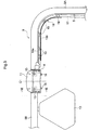
- is a rear view showing a harness and a harness cover;
- Fig. 6
- is a perspective view showing the harness and the harness cover; and
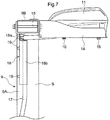
- Fig. 7
- is a view in section taken on VII-VII in
Fig. 5 . - Embodiments for carrying out the invention will be described with reference to drawings.
-
Fig. 1 andFig. 2 show a tractor (work vehicle). The tractor includes atraveling vehicle body 1. Thetraveling vehicle body 1 is configured by a four-wheel-drive traveling vehicle body, for example. Thetraveling vehicle body 1 includes a pair of drivable-steerable right and leftfront wheels 2F, and a pair of drivable right and leftrear wheels 2B. A pair of right andleft fenders 3 are disposed for covering the pair of right and leftrear wheels 2B, respectively. - At a front half part of
traveling vehicle body 1, there is provided anengine section 4. At theengine section 4, there are provided an engine E and ahood 5 which houses the engine E. At a rear part of thetraveling vehicle body 1, there is provided adriving section 6 on which a driver rides. Thedriving section 6 includes a driver'sseat 7 on which the driver sits, and asteering wheel 8 for steering thetraveling vehicle body 1. A rollover protection structure (ROPS) 9 is provided around the driver'sseat 7. At a rear end part of thetraveling vehicle body 1, there is provided alink mechanism 10 to which an implement (not shown) such as a rotary cultivator or the like is attached. - The tractor includes a global positioning system (GPS) antenna unit 11 (receiving device) and an inertial measurement unit (not shown). The
GPS antenna unit 11 is a unit which receives positional information from a global positioning system (GPS) satellite and measures a position of thetraveling vehicle body 1 based on the received positional information. The inertial measurement unit is a unit which measures inertial information (such as a yaw angle, a pitch angle and a roll angle) of thetraveling vehicle body 1. The tractor includes an automatic steering mechanism (not shown) which automatically steers thetraveling vehicle body 1 so as to allow the travelingvehicle body 1 to travel along a target travel route based on the position of the travelingvehicle body 1 measured by theGPS antenna unit 11 and on the inertial information of thetraveling vehicle body 1 measured by the inertial measurement unit. - As shown in
Fig. 3 andFig. 4 , theROPS 9 is located on lateral outer sides relative to the driver'sseat 7; and includes a pair of right andleft strut parts 9A which extend in the vertical direction, and abeam part 9B which is located upward of the driver'sseat 7 and extends in a right-left direction of the vehicle body. TheROPS 9 is configured to be foldable rearward around an axis X1 which extends in the right-left direction of the vehicle body. -
Rear combination lamps 12 are attached to theleft strut part 9A and theright strut part 9A, respectively. In theleft strut part 9A and theright strut part 9A, there are respectively provided attachingparts 9a to which therear combination lamps 12 are attached, respectively. A low-speed vehicle mark 13 is attached to thebeam part 9B. The low-speed vehicle mark 13 is arranged at a position deviated to a left side relative to a right-left center C1 of thebeam part 9B (a right-left center of the vehicle body). - As shown in
Fig. 3 to Fig. 7 , theGPS antenna unit 11 is supported to an upper part of theROPS 9. Specifically, theGPS antenna unit 11 is supported to a right-left central part of thebeam part 9B, a right-left center thereof being in alignment with the right-left center of the vehicle body (the right-left center C1 of thebeam part 9B). At the right-left center of thebeam part 9B, there is provided aGPS stay 14 which supports theGPS antenna unit 11. The GPS stay 14 is supported (cantilevered) to thebeam part 9B, theGPS stay 14 being projecting rearward from thebeam part 9B. The GPS stay 14 is fixed to thebeam part 9B by abolt 15 which penetrate through thebeam part 9B from front. TheGPS antenna unit 11 is fixed to theGPS stay 14 by abolt 16 which penetrate through the GPS stay 14 from below, theGPS antenna unit 11 being mounted on and supported to theGPS stay 14. - The
harness 17 for theGPS antenna unit 11 is provided between/across theGPS antenna unit 11 and a controller (not shown) which controls the automatic steering mechanism and the like. Theharness 17 is routed along the outer peripheral face of theROPS 9. Specifically, theharness 17 is routed along an inner side part S in the outer peripheral face of theROPS 9, the inner side part S being directed to an inner side of the vehicle body. Theharness 17 is routed between/across a right-side part of thebeam part 9B and theright strut part 9A, theharness 17 being drawn out from a right-side part of theGPS antenna unit 11 to an opposite side (right side) of a side at which the low-speed vehicle mark 13 is located, relative to theGPS antenna unit 11. Theharness 17 extends downward along a front side of aright attaching part 9a, and penetrates through a rear-side part relative to the axis X1 in theright fender 3 and extends to the controller. - There is provided a
cover 18 which is configured to cover theharness 17. Thecover 18 extends between/across the right-side part of thebeam part 9B and an upper part of theright strut part 9A. Theharness 17 is fixed by fixingtools 19 to the cover 18 (vertical part 18a) and theright attaching part 9a. Thecover 18 includes a part which extends along the right-side part of thebeam part 9B, a part which extends along the upper part of theright strut part 9A, and a part which extends along a curved part between/across thebeam part 9B and theright strut part 9A. Thecover 18 is configured to cover theharness 17 from front and from a side opposing to the inner side part S (from below and from a lateral inner side, for example). In order to allow theharness 17 to enter from a rear side to the inside of thecover 18, thecover 18 is formed in a cross-sectional shape (an approximately L-letter cross-sectional shape) which is opened rearward. Thecover 18 includes thevertical part 18a which is vertical to the inner side part S, and abottom part 18b extending rearward from an end part, in thevertical part 18a, on a side opposing to the inner side part S, thebottom part 18b extending parallel with the inner side part S. -
- (1) In the foregoing embodiment, the
harness 17 is routed along the inner side part S in the outer peripheral face of theROPS 9, the inner side part S being directed to an inner side of the vehicle body. However, theharness 17 may be routed along an outer side part in the outer peripheral face of the ROPS 9 (such as a front face, a rear face, an upper face and a lateral outer face of the ROPS 9), the outer side part being directed to an outer side of the vehicle body. - (2) In the foregoing embodiment, the
harness 17 is routed between/across the right-side part of thebeam part 9B and theright strut part 9A. However, theharness 17 may be routed between/across a left-side part of thebeam part 9B and theleft strut part 9A. - (3) In the foregoing embodiment, the
cover 18 extends between/across the right-side part of thebeam part 9B and the upper part of theright strut part 9A. That is, thecover 18 does not cover a part in theharness 17 lower than the upper part of theright strut part 9A. However, thecover 18 may extend between/across the right-side part of thebeam part 9B and a lower part of theright strut part 9A. That is, thecover 18 may cover the part in theharness 17 lower than the upper part of theright strut part 9A, too. - (4) In the foregoing embodiment, in order to allow the
harness 17 to enter from a rear side into the inside of thecover 18, thecover 18 is formed in the cross-sectional shape which is opened rearward. However, in order to allow theharness 17 to enter from a front side into the inside of thecover 18, thecover 18 may be formed in a cross-sectional shape which is opened forward. Still alternatively, thecover 18 may be formed in an approximately U-shaped cross-sectional shape (a cross-sectional shape which is not opened forward, rearward or downward). - The invention can be used for a work vehicle (a tractor, for example) having a receiving device which receives positional information from a satellite.
-
- 7
- Driver's seat
- 9
- ROPS
- 9A
- Strut part
- 9B
- Beam part
- 11
- GPS antenna unit (receiving device)
- 17
- Harness
- 18
- Cover
- 19
- Fixing tool
- S
- Inner side part
Claims (5)
- A work vehicle comprising:- a rollover protection structure (ROPS) which is disposed around a driver's seat; and- a receiving device which is supported to an upper part of the ROPS and receives positional information from a satellite;- wherein a harness for the receiving device is routed along an outer peripheral face of the ROPS, and- wherein a cover which is configured to cover the harness is provided.
- The work vehicle according to claim 1, wherein the harness is routed along an inner side part in the outer peripheral face of the ROPS, the inner side part being directed to an inner side of a vehicle body, and
the cover is configured to cover the harness from front and below. - The work vehicle according to claim 2, wherein the ROPS is located at lateral outside relative to the driver's seat, the ROPS including a pair of right and left strut parts which extend in a vertical direction, and a beam part which is located at an upper side relative to the driver's seat and extends in a right-left direction of the vehicle body,- the receiving device is supported to the beam part,- the harness is routed between/across the beam part and the strut part, and- the cover extends between/across the beam part and the strut part.
- The work vehicle according to claim 3, wherein, in order to allow the harness to enter from a rear side to an inside of the cover, the cover is formed in a cross-sectional shape which is opened rearward.
- The work vehicle according to any one of claims 1 to 4, wherein the harness is fixed to the cover by a fixing tool.
Applications Claiming Priority (2)
| Application Number | Priority Date | Filing Date | Title |
|---|---|---|---|
| JP2018238889A JP7074657B2 (en) | 2018-12-20 | 2018-12-20 | Work vehicle |
| PCT/JP2019/049344 WO2020129961A1 (en) | 2018-12-20 | 2019-12-17 | Work vehicle |
Publications (2)
| Publication Number | Publication Date |
|---|---|
| EP3900984A1 true EP3900984A1 (en) | 2021-10-27 |
| EP3900984A4 EP3900984A4 (en) | 2022-09-28 |
Family
ID=71101767
Family Applications (1)
| Application Number | Title | Priority Date | Filing Date |
|---|---|---|---|
| EP19900838.4A Pending EP3900984A4 (en) | 2018-12-20 | 2019-12-17 | WORK VEHICLE |
Country Status (6)
| Country | Link |
|---|---|
| US (1) | US11529920B2 (en) |
| EP (1) | EP3900984A4 (en) |
| JP (5) | JP7074657B2 (en) |
| KR (1) | KR102493699B1 (en) |
| CN (1) | CN112004720B (en) |
| WO (1) | WO2020129961A1 (en) |
Families Citing this family (4)
| Publication number | Priority date | Publication date | Assignee | Title |
|---|---|---|---|---|
| JP7074657B2 (en) * | 2018-12-20 | 2022-05-24 | 株式会社クボタ | Work vehicle |
| JP2023038158A (en) * | 2021-09-06 | 2023-03-16 | ヤンマーホールディングス株式会社 | work vehicle |
| JP7662459B2 (en) * | 2021-09-06 | 2025-04-15 | ヤンマーホールディングス株式会社 | Work vehicles |
| JP2023167449A (en) * | 2022-05-12 | 2023-11-24 | ヤンマーホールディングス株式会社 | work vehicle |
Family Cites Families (30)
| Publication number | Priority date | Publication date | Assignee | Title |
|---|---|---|---|---|
| DE68913364T2 (en) * | 1988-06-10 | 1994-06-01 | United Technologies Automotive | Modular roof cladding with electrical wiring. |
| JPH0265655U (en) * | 1988-11-09 | 1990-05-17 | ||
| JPH0266349U (en) * | 1988-11-10 | 1990-05-18 | ||
| JPH08207678A (en) * | 1995-02-03 | 1996-08-13 | Ishikawajima Shibaura Mach Co Ltd | Wiring structure of electrical equipment |
| JP2004306811A (en) * | 2003-04-08 | 2004-11-04 | Komatsu Ltd | Mounting structure for optional wiring of work vehicle |
| JP4601543B2 (en) | 2005-11-25 | 2010-12-22 | 株式会社クボタ | Work vehicle |
| JP5572402B2 (en) * | 2010-01-21 | 2014-08-13 | ヤンマー株式会社 | Self-propelled vehicle |
| JP5210340B2 (en) * | 2010-03-08 | 2013-06-12 | 株式会社クボタ | Mower |
| US20140168009A1 (en) * | 2012-12-17 | 2014-06-19 | Trimble Navigation Ltd. | Multi-IMU INS for vehicle control |
| JP2015116170A (en) * | 2013-12-20 | 2015-06-25 | 三菱農機株式会社 | Semi crawler type tractor |
| JP2016084095A (en) * | 2014-10-28 | 2016-05-19 | ヤンマー株式会社 | Work vehicle |
| KR102113386B1 (en) * | 2014-11-13 | 2020-05-20 | 얀마 가부시키가이샤 | Agricultural work vehicle |
| JP6704130B2 (en) * | 2015-02-25 | 2020-06-03 | 井関農機株式会社 | Agricultural work support system |
| JP6445402B2 (en) * | 2015-07-06 | 2018-12-26 | ヤンマー株式会社 | Work vehicle |
| JP2017190010A (en) * | 2016-04-12 | 2017-10-19 | 三菱マヒンドラ農機株式会社 | Tractor |
| JP6776863B2 (en) * | 2016-12-13 | 2020-10-28 | 井関農機株式会社 | Work vehicle |
| WO2018124058A1 (en) * | 2016-12-26 | 2018-07-05 | 株式会社クボタ | Location positioning system and positioning device |
| WO2018139143A1 (en) * | 2017-01-24 | 2018-08-02 | 株式会社クボタ | Combine, harvester, and automatic steering system |
| KR102108672B1 (en) | 2017-02-08 | 2020-05-07 | 얀마 가부시키가이샤 | Antenna unit for work vehicles, and work vehicles |
| JP6932655B2 (en) | 2017-02-08 | 2021-09-08 | ヤンマーパワーテクノロジー株式会社 | Work vehicle |
| JP6816631B2 (en) * | 2017-04-28 | 2021-01-20 | 井関農機株式会社 | Work vehicle |
| JP6892363B2 (en) * | 2017-10-06 | 2021-06-23 | ヤンマーパワーテクノロジー株式会社 | Tractor |
| CN111278684B (en) * | 2017-12-18 | 2023-08-22 | 株式会社久保田 | Tractor and work vehicle |
| KR102745013B1 (en) * | 2017-12-18 | 2024-12-20 | 가부시끼 가이샤 구보다 | Work vehicles and tractors |
| JP7074656B2 (en) * | 2018-12-20 | 2022-05-24 | 株式会社クボタ | Work vehicle |
| JP7120907B2 (en) * | 2018-12-20 | 2022-08-17 | 株式会社クボタ | traveling work machine |
| JP7074657B2 (en) * | 2018-12-20 | 2022-05-24 | 株式会社クボタ | Work vehicle |
| JP2020103093A (en) * | 2018-12-26 | 2020-07-09 | 株式会社クボタ | Work vehicle |
| JP6716763B1 (en) * | 2019-09-06 | 2020-07-01 | 株式会社クボタ | Work vehicle |
| CN114786463A (en) * | 2019-12-25 | 2022-07-22 | 株式会社久保田 | Working machine |
-
2018
- 2018-12-20 JP JP2018238889A patent/JP7074657B2/en active Active
-
2019
- 2019-12-17 US US17/046,009 patent/US11529920B2/en active Active
- 2019-12-17 EP EP19900838.4A patent/EP3900984A4/en active Pending
- 2019-12-17 KR KR1020207028768A patent/KR102493699B1/en active Active
- 2019-12-17 CN CN201980026068.8A patent/CN112004720B/en active Active
- 2019-12-17 WO PCT/JP2019/049344 patent/WO2020129961A1/en not_active Ceased
-
2022
- 2022-05-11 JP JP2022078252A patent/JP7359902B2/en active Active
-
2023
- 2023-09-28 JP JP2023167136A patent/JP7504274B2/en active Active
-
2024
- 2024-06-10 JP JP2024093775A patent/JP7728922B2/en active Active
-
2025
- 2025-08-12 JP JP2025134292A patent/JP2025159116A/en active Pending
Also Published As
| Publication number | Publication date |
|---|---|
| KR102493699B1 (en) | 2023-02-06 |
| KR20200125718A (en) | 2020-11-04 |
| JP7359902B2 (en) | 2023-10-11 |
| JP2025159116A (en) | 2025-10-17 |
| JP2022116037A (en) | 2022-08-09 |
| US11529920B2 (en) | 2022-12-20 |
| JP2020100234A (en) | 2020-07-02 |
| JP7074657B2 (en) | 2022-05-24 |
| JP7504274B2 (en) | 2024-06-21 |
| CN112004720B (en) | 2023-09-08 |
| US20210362666A1 (en) | 2021-11-25 |
| CN112004720A (en) | 2020-11-27 |
| JP7728922B2 (en) | 2025-08-25 |
| EP3900984A4 (en) | 2022-09-28 |
| JP2024107259A (en) | 2024-08-08 |
| WO2020129961A1 (en) | 2020-06-25 |
| JP2023175882A (en) | 2023-12-12 |
Similar Documents
| Publication | Publication Date | Title |
|---|---|---|
| US11529920B2 (en) | Work vehicle | |
| US11535172B2 (en) | Work vehicle | |
| JP2019070544A (en) | Work vehicle | |
| JP2025159116A5 (en) | ||
| US11427134B2 (en) | Tractor | |
| EP4144591A1 (en) | Work vehicle | |
| JP6887370B2 (en) | Tractor | |
| JP6820828B2 (en) | Tractor | |
| JP2025102863A (en) | Work vehicles | |
| CN115775969A (en) | Working vehicle | |
| US12631764B2 (en) | Work vehicle |
Legal Events
| Date | Code | Title | Description |
|---|---|---|---|
| STAA | Information on the status of an ep patent application or granted ep patent |
Free format text: STATUS: THE INTERNATIONAL PUBLICATION HAS BEEN MADE |
|
| PUAI | Public reference made under article 153(3) epc to a published international application that has entered the european phase |
Free format text: ORIGINAL CODE: 0009012 |
|
| STAA | Information on the status of an ep patent application or granted ep patent |
Free format text: STATUS: REQUEST FOR EXAMINATION WAS MADE |
|
| 17P | Request for examination filed |
Effective date: 20200929 |
|
| AK | Designated contracting states |
Kind code of ref document: A1 Designated state(s): AL AT BE BG CH CY CZ DE DK EE ES FI FR GB GR HR HU IE IS IT LI LT LU LV MC MK MT NL NO PL PT RO RS SE SI SK SM TR |
|
| DAV | Request for validation of the european patent (deleted) | ||
| DAX | Request for extension of the european patent (deleted) | ||
| A4 | Supplementary search report drawn up and despatched |
Effective date: 20220826 |
|
| RIC1 | Information provided on ipc code assigned before grant |
Ipc: B60R 16/02 20060101ALI20220822BHEP Ipc: B60R 11/02 20060101AFI20220822BHEP |
|
| STAA | Information on the status of an ep patent application or granted ep patent |
Free format text: STATUS: EXAMINATION IS IN PROGRESS |
|
| 17Q | First examination report despatched |
Effective date: 20240930 |