EP3900818A1 - Reactor and method for performing a chemical reaction - Google Patents
Reactor and method for performing a chemical reaction Download PDFInfo
- Publication number
- EP3900818A1 EP3900818A1 EP20171196.7A EP20171196A EP3900818A1 EP 3900818 A1 EP3900818 A1 EP 3900818A1 EP 20171196 A EP20171196 A EP 20171196A EP 3900818 A1 EP3900818 A1 EP 3900818A1
- Authority
- EP
- European Patent Office
- Prior art keywords
- reactor
- gas
- reaction
- reactor vessel
- reaction tubes
- Prior art date
- Legal status (The legal status is an assumption and is not a legal conclusion. Google has not performed a legal analysis and makes no representation as to the accuracy of the status listed.)
- Withdrawn
Links
Images


Classifications
-
- B—PERFORMING OPERATIONS; TRANSPORTING
- B01—PHYSICAL OR CHEMICAL PROCESSES OR APPARATUS IN GENERAL
- B01J—CHEMICAL OR PHYSICAL PROCESSES, e.g. CATALYSIS OR COLLOID CHEMISTRY; THEIR RELEVANT APPARATUS
- B01J8/00—Chemical or physical processes in general, conducted in the presence of fluids and solid particles; Apparatus for such processes
- B01J8/001—Controlling catalytic processes
-
- B—PERFORMING OPERATIONS; TRANSPORTING
- B01—PHYSICAL OR CHEMICAL PROCESSES OR APPARATUS IN GENERAL
- B01J—CHEMICAL OR PHYSICAL PROCESSES, e.g. CATALYSIS OR COLLOID CHEMISTRY; THEIR RELEVANT APPARATUS
- B01J19/00—Chemical, physical or physico-chemical processes in general; Their relevant apparatus
- B01J19/0006—Controlling or regulating processes
- B01J19/002—Avoiding undesirable reactions or side-effects, e.g. avoiding explosions, or improving the yield by suppressing side-reactions
-
- B—PERFORMING OPERATIONS; TRANSPORTING
- B01—PHYSICAL OR CHEMICAL PROCESSES OR APPARATUS IN GENERAL
- B01J—CHEMICAL OR PHYSICAL PROCESSES, e.g. CATALYSIS OR COLLOID CHEMISTRY; THEIR RELEVANT APPARATUS
- B01J19/00—Chemical, physical or physico-chemical processes in general; Their relevant apparatus
- B01J19/08—Processes employing the direct application of electric or wave energy, or particle radiation; Apparatus therefor
- B01J19/087—Processes employing the direct application of electric or wave energy, or particle radiation; Apparatus therefor employing electric or magnetic energy
-
- B—PERFORMING OPERATIONS; TRANSPORTING
- B01—PHYSICAL OR CHEMICAL PROCESSES OR APPARATUS IN GENERAL
- B01J—CHEMICAL OR PHYSICAL PROCESSES, e.g. CATALYSIS OR COLLOID CHEMISTRY; THEIR RELEVANT APPARATUS
- B01J8/00—Chemical or physical processes in general, conducted in the presence of fluids and solid particles; Apparatus for such processes
- B01J8/02—Chemical or physical processes in general, conducted in the presence of fluids and solid particles; Apparatus for such processes with stationary particles, e.g. in fixed beds
- B01J8/06—Chemical or physical processes in general, conducted in the presence of fluids and solid particles; Apparatus for such processes with stationary particles, e.g. in fixed beds in tube reactors; the solid particles being arranged in tubes
- B01J8/067—Heating or cooling the reactor
-
- B—PERFORMING OPERATIONS; TRANSPORTING
- B01—PHYSICAL OR CHEMICAL PROCESSES OR APPARATUS IN GENERAL
- B01J—CHEMICAL OR PHYSICAL PROCESSES, e.g. CATALYSIS OR COLLOID CHEMISTRY; THEIR RELEVANT APPARATUS
- B01J2208/00—Processes carried out in the presence of solid particles; Reactors therefor
- B01J2208/00008—Controlling the process
- B01J2208/00628—Controlling the composition of the reactive mixture
- B01J2208/00637—Means for stopping or slowing down the reaction
-
- B—PERFORMING OPERATIONS; TRANSPORTING
- B01—PHYSICAL OR CHEMICAL PROCESSES OR APPARATUS IN GENERAL
- B01J—CHEMICAL OR PHYSICAL PROCESSES, e.g. CATALYSIS OR COLLOID CHEMISTRY; THEIR RELEVANT APPARATUS
- B01J2219/00—Chemical, physical or physico-chemical processes in general; Their relevant apparatus
- B01J2219/00049—Controlling or regulating processes
- B01J2219/00245—Avoiding undesirable reactions or side-effects
- B01J2219/00259—Preventing runaway of the chemical reaction
- B01J2219/00263—Preventing explosion of the chemical mixture
-
- B—PERFORMING OPERATIONS; TRANSPORTING
- B01—PHYSICAL OR CHEMICAL PROCESSES OR APPARATUS IN GENERAL
- B01J—CHEMICAL OR PHYSICAL PROCESSES, e.g. CATALYSIS OR COLLOID CHEMISTRY; THEIR RELEVANT APPARATUS
- B01J2219/00—Chemical, physical or physico-chemical processes in general; Their relevant apparatus
- B01J2219/00049—Controlling or regulating processes
- B01J2219/00245—Avoiding undesirable reactions or side-effects
- B01J2219/00268—Detecting faulty operations
-
- B—PERFORMING OPERATIONS; TRANSPORTING
- B01—PHYSICAL OR CHEMICAL PROCESSES OR APPARATUS IN GENERAL
- B01J—CHEMICAL OR PHYSICAL PROCESSES, e.g. CATALYSIS OR COLLOID CHEMISTRY; THEIR RELEVANT APPARATUS
- B01J2219/00—Chemical, physical or physico-chemical processes in general; Their relevant apparatus
- B01J2219/00049—Controlling or regulating processes
- B01J2219/00245—Avoiding undesirable reactions or side-effects
- B01J2219/00272—Addition of reaction inhibitor
-
- Y—GENERAL TAGGING OF NEW TECHNOLOGICAL DEVELOPMENTS; GENERAL TAGGING OF CROSS-SECTIONAL TECHNOLOGIES SPANNING OVER SEVERAL SECTIONS OF THE IPC; TECHNICAL SUBJECTS COVERED BY FORMER USPC CROSS-REFERENCE ART COLLECTIONS [XRACs] AND DIGESTS
- Y02—TECHNOLOGIES OR APPLICATIONS FOR MITIGATION OR ADAPTATION AGAINST CLIMATE CHANGE
- Y02P—CLIMATE CHANGE MITIGATION TECHNOLOGIES IN THE PRODUCTION OR PROCESSING OF GOODS
- Y02P20/00—Technologies relating to chemical industry
- Y02P20/50—Improvements relating to the production of bulk chemicals
- Y02P20/54—Improvements relating to the production of bulk chemicals using solvents, e.g. supercritical solvents or ionic liquids
Definitions
- the invention relates to a reactor and a method for carrying out a chemical reaction according to the preambles of the independent claims.
- reactors are used in which one or more reactants are passed through heated reaction tubes and converted there catalytically or non-catalytically.
- the heating is used in particular to overcome the activation energy required for the chemical reaction that is taking place.
- the overall reaction can be endothermic or, after the activation energy has been overcome, exothermic.
- the present invention particularly relates to highly endothermic reactions.
- steam cracking steam cracking
- various reforming processes in particular steam reforming, dry reforming (carbon dioxide reforming), mixed reforming processes, processes for the dehydrogenation of alkanes and the like.
- steam cracking the reaction tubes are guided through the reactor in the form of coils, which have at least one reverse bend in the reactor, whereas in steam reforming tubes that run through the reactor without a reverse bend are typically used.
- the invention is suitable for all such methods and designs of reaction tubes.
- the articles "Ethylene”, “Gas Production” and “Propene” in Ullmann's Encyclopedia of Industrial Chemistry for example the publications from April 15, 2009, DOI: 10.1002 / 14356007.a10_045.pub2, from December 15, 2006, DOI: 10.1002 / 14356007.a12_169.pub2 , and of June 15, 2000, DOI: 10.1002 / 14356007.a22_211.
- the reaction tubes of corresponding reactors are conventionally heated by using burners.
- the reaction tubes are guided through a combustion chamber in which the burners are also arranged.
- reaction tubes in which an electric current flows through the reaction tubes
- indirect electrical heating can, as among other things in the WO 2020/002326 A1 described, take place in the form of an external electrical heating. Internal heating is also possible, for example in the WO 2019/228798 A1 disclosed.
- inductive electrical heating of the of reaction tubes or a catalyst bed in addition to resistance or impedance heating, inductive electrical heating of the of reaction tubes or a catalyst bed, as in the WO 2017/072057 A1 described.
- the inductive heating can, for example, heat an internal or external heating element or the reaction tubes themselves.
- a direct (non-inductive) heating of a reaction tube is also possible DE 10 2015 004 121 A1 disclosed.
- Basic concepts with multi-phase or single-phase alternating current or direct current can be implemented for heating.
- direct heating of reactors with direct current or with single-phase alternating current a star connection with a potential-free star point cannot be implemented, but the power supply can basically be implemented in a similar way as with multi-phase direct current.
- the present invention is suitable for all variants of electrical heating.
- the present invention has the task of specifying measures which take these aspects into account and in this way allow an advantageous operation of an electrically heated reactor.
- the present invention proposes a reactor and a method for carrying out a chemical reaction according to the preambles of the independent claims. Refinements are the subject matter of the dependent claims and the description below.
- furnace In an electrified furnace concept (the term "furnace” is usually understood to denote a corresponding reactor or at least its thermally insulated reaction space) on which the present invention is based, for example, reaction tubes or corresponding tube sections thereof (hereinafter also referred to as “tubes “referred to) themselves as electrical resistors used to generate heat.
- This direct approach has the advantage of a higher degree of efficiency compared to indirect heating by external electrical heating elements as well as a higher achievable heat flux density.
- any other type of electrical heating direct or indirect, as resistance, Impedance or induction heating, using single or multi-phase alternating current or direct current
- the current can be fed into the directly heated reaction tubes via M separately connected phases.
- the current-conducting reaction tubes, which are connected to the M phases, can also be electrically connected to a star point at the other end.
- the number of phases M is in particular 3, corresponding to the number of phases of conventional three-phase current sources or networks.
- the present invention is not restricted to the use of three phases, but can also be used with a larger number of phases, for example a number of phases of 4, 5, 6, 7 or 8.
- a phase offset is particularly 360 ° / M, i.e. 120 ° for a three-phase alternating current.
- the measures proposed according to the invention explained below are equally suitable for the use of single-phase alternating current and direct current, and the present invention can be used both in alternating current and in direct current heated reactors or in corresponding mixed forms.
- the present invention is also suitable for use in indirectly heated reaction tubes.
- a direct current arrangement for example, only the type of current source and the area of the reaction tubes or corresponding current-loaded sections opposite the current feed differ from an alternating current arrangement. In the latter, an electrical connection between different pipe sections is only carried out as an option. Since there is no potential-free star point in a direct current arrangement, suitable current discharge elements are to be provided that the Lead the current flow safely to the outside again. The latter can be implemented in the same way as the current feeds described below.
- the present invention relates to the protection of electrically heated reactors of the type described, which is necessary in particular in the event of damage to the reaction tubes ("coil ruptures").
- one or more reaction tubes can in particular be severed completely; however, the present invention is also beneficial for minor leakages.
- the present invention relates to a reactor for carrying out a chemical reaction, which has a reactor vessel (ie a thermally insulated or at least partially insulated area), a or has a plurality of reaction tubes and means for electrically heating the one or more reaction tubes.
- a reactor vessel ie a thermally insulated or at least partially insulated area
- the reactor proposed according to the invention is set up in particular to carry out a chemical reaction at a temperature level explained below for high-temperature reactions.
- the means for electrical heating can be designed as explained extensively above.
- it can be a means for feeding current into the one or more reaction tubes, which cause a current to flow in the one or more reaction tubes and a corresponding heating, for example rigid current rods guided into the reactor, but also means for indirect heating such as resistance and / or inductive heating devices that transfer heat conductively and / or by thermal radiation to the one or more reaction tubes or that generate eddy currents in the one or more reaction tubes or a catalyst bed, for example, and thus cause heating.
- indirect heating such as resistance and / or inductive heating devices that transfer heat conductively and / or by thermal radiation to the one or more reaction tubes or that generate eddy currents in the one or more reaction tubes or a catalyst bed, for example, and thus cause heating.
- the reactor vessel has one or more outflow openings that are permanently open or are set up to open above a predetermined pressure level, and gas feed means are provided which are set up to feed an inerting gas into the reactor vessel.
- the gas feed means include, for example, feed nozzles or openings that open into the reactor vessel, as well as lines and a gas reservoir connected to them, whereby the interior of the reactor vessel can be charged with the inerting gas.
- the reactor vessel is in particular a chamber that is predominantly, i.e. at least 90, 95 or 99% surrounded by a thermally insulating wall.
- the inerting gas can be a gas or a gas mixture, the nitrogen, carbon dioxide and / or argon in a superatmospheric content, or the gas feed means are set up to provide a corresponding inerting gas, for example by keeping the corresponding inerting gas available or by mixing clean gases or adding clean gases to air.
- the content of a non-combustible gas can be more than 50%, 60%, 70%, 80% or 90%.
- An inerting gas does not have to be a pure "inert gas" in the classically understood sense; Rather, it is sufficient if the inerting gas, in particular due to its content of a non-combustible gas, at least partially reduces the ignitable mixture area, that is to say reduces the risk of ignition, explosion or detonation.
- An inerting gas for use in the context of the present invention can in particular have a subatmospheric oxygen content, for example an oxygen content of less than 10%, 5%, 1%, 0.5% or 0.1%.
- An inerting gas can in particular also be (completely or essentially) free of oxygen.
- the present invention creates a containment with a conditioned atmosphere that is used for thermal insulation and for the safety-related safeguarding of high-temperature reactors in which the energy input takes place electrically.
- completely electrical heating can be provided, ie the heating of the reaction tubes takes place at least within the reactor vessel, advantageously predominantly or exclusively by thermal heating, ie at least 90, 95 or 99% of the amount of heat introduced here, in particular of the total amount of heat introduced here Amount of heat, takes place through electrical heating means.
- An input of heat via a gas mixture passed through the one or more reaction tubes is not taken into account here, so that this proportion is in particular transferred to the wall of the one or more reaction tubes inside the reactor container or inside the reactor container in the wall or a catalyst bed generated heat.
- the invention thus describes a containment for high-temperature reactors charged with hydrocarbons (a high-temperature reaction here in particular denotes a reaction which takes place at a temperature of more than 500 ° C. and in particular from 700 to 1,000 ° C.) electrical heating that 1. provides an inert atmosphere in the vicinity of the pipes, and 2. is not permanently closed.
- a high-temperature reaction here in particular denotes a reaction which takes place at a temperature of more than 500 ° C. and in particular from 700 to 1,000 ° C.
- electrical heating 1. provides an inert atmosphere in the vicinity of the pipes, and 2. is not permanently closed.
- the use for electrically heated reactors in which the process gas temperature is close to or above the self-ignition temperature of the hydrocarbons contained in the process gas is particularly preferred.
- process gas denotes a gas or gas mixture which flows through the one or more reaction tubes.
- Embodiments of the present invention differ in particular in the design of the one or more outflow openings that are permanently open or that are set up to open above a predetermined pressure level.
- a combination of appropriately designed outflow openings is also possible in principle.
- the one or more outflow openings is or are permanently open. This means that the one or more outflow openings do not oppose or oppose any mechanical resistance to the outflow or inflow of fluid into or out of the reactor vessel apart from the possibly existing narrowing of the flow cross-section. The one or more openings is or are therefore not closed.
- the one or more outflow openings is or are set up for the opening above the predetermined pressure level.
- the one or more outflow openings is or are closed below the predetermined pressure level and is or are set up for a temporary or permanent opening when the predetermined pressure level is reached.
- a "permanent" opening is understood to mean, in particular, an irreversible opening, so that in this embodiment there is no reclosure after the pressure level has subsequently fallen below the specified level by releasing gas. In the case of a "temporary" opening, on the other hand, a re-closure takes place.
- the one or more outflow openings can be, for example, one or more spring-loaded or spring-loaded for opening at the predetermined pressure level have load-acted flaps which have an opening resistance defined by the spring or load characteristics and therefore only open from a corresponding pressure.
- one or more bursting disks or pressure relief valves of a type known per se can also be used. It is also possible to detect a pressure value, for example by means of a sensor, and to trigger an opening mechanism of any type, for example an ignition mechanism or an electro-actuator drive, when a predetermined threshold value is exceeded. This makes it possible, if necessary, to release a sufficiently large cross section within a short response time, which cross section is kept closed in the manner explained during normal operation.
- the reactor can be set up for constant purging with inert gas.
- the gas feed means explained are set up for a continuous feed of the inerting gas into the reactor vessel.
- the inerting gas can in particular predominantly flow out via the one or more permanently open outflow openings, but possibly also via further outflow openings, in particular unavoidable or deliberately created gas leaks or bypasses, for example to an existing chimney.
- one or more predetermined criteria can include, for example, reaching a predetermined pressure value and / or a predetermined concentration, for example a minimum and tolerable oxygen content.
- one criterion can also be that the reactor vessel is put into operation for the first time. In particular, it can be a continuous measurement can be carried out and the injection of inerting gas can always be initiated when corresponding measured values indicate that the specified criteria are no longer met.
- the one-time or periodic application of inerting gas can be provided, in particular in the second group of embodiments, below the pressure value for the opening of the one or more outflow openings, since here a free outflow of the inerting gas is prevented and the inerting gas is kept in the reactor vessel for longer periods of time can.
- the reactor is set up to operate the reactor vessel at a sub-atmospheric pressure level.
- Means for forming a gas flow out of the reactor are provided here.
- the one or more outflow openings which is or are permanently open in this group of embodiments, can be connected to a chimney that has a chimney mouth at a sufficient height, permanently open. Due to the high temperatures in the reactor vessel and the resulting lower density of the gas volume contained, this results in a static negative pressure in the reactor vessel.
- the use of fans, for example until a corresponding static negative pressure is formed, can also be provided in this context.
- the reactor is set up for operation of the reactor vessel at a pressure level above atmospheric. This can be achieved in particular in that the inerting gas is fed in up to a pressure level above atmospheric which is below an opening pressure of the outflow openings.
- the system which has been inerted to a certain extent and is "open" to the environment, according to the first group of embodiments (in particular with a slight negative pressure in the reactor vessel as a result of the chimney effect) or also the "openable" system according to the second group of embodiments of the present invention (in particular can be operated with a certain overpressure in the reactor vessel) the rate of pressure increase in the event of an escape of Hydrocarbons Damage to the reaction tubes, limit to a tolerable level that does not violate the design limits of the reactor vessel.
- the oxygen content present there can be reduced through the concept of a reactor vessel charged with inerting gas.
- the conversion rate of the hydrocarbons escaping in the event of damage and thus the significant additional increase in volume (as a result of the introduction of heat from the reaction) scales as a first approximation with the oxygen partial pressure in the box.
- the feeding of the inerting gas means that the walls of the reactor vessel do not have to be made completely gas-tight, which, due to the high temperatures at certain points, requires a very high amount of material, for example the use of temperature-resistant bellows structures and the like to be carried out.
- air may possibly be sucked into the reactor vessel via corresponding leaks, but this is removed and diluted accordingly by the continuous flow caused by the chimney.
- Safety problems when using inerting gases or components thereof that may impede breathing can be prevented in this way.
- the proposed concept of the reactor vessel charged with inerting gas enables the oxygen content to be reduced here.
- the conversion rate of the exiting hydrocarbons and thus the relevant additional rate of increase in volume correlates to a first approximation with the oxygen partial pressure. This correlation is summarized in Table 1 below, with ⁇ O 2 denoting the oxygen partial pressure and V reak denoting the rate of increase in volume caused by the reaction.
- the gas feed means are therefore advantageously set up to set a maximum oxygen content in the reaction vessel on the basis of a dimensioning of the chimney or chimneys.
- Table 1 ⁇ O 2 [vol.%] V reak [m 3 / s] 21 218 15th 156 10 104 5 52 3 31 1 10 0.1 (almost inert) 1
- a sufficiently good seal against the environment is always decisive in order to prevent the entry of oxygen-containing false air as far as possible or in a sufficient manner. As explained, however, a complete seal is not required.
- the inerting gas is used to set a maximum oxygen content in the reaction container and / or the connection chamber, which is or are selected in the first group of configurations when a chimney is present on the basis of a dimensioning of the chimney or chimneys the gas feed means are set up for feeding in inerting gas or for setting the oxygen content on this basis.
- the gas feed means can also be set up, in particular, to feed in in such a way that a target pressure is not exceeded.
- a feed can also take place on the basis of an oxygen concentration or a target pressure and a chimney dimensioning.
- a quantity of the inerting gas fed in can be regulated by appropriate regulating means, in particular on the basis of an oxygen measurement in the reactor vessel or in the chimney, if present, whereby the oxygen content can be kept constant during operation.
- a corresponding safety concept can also include, for example, that an operation of the reactor is prevented or remains if the measured oxygen content exceeds a target oxygen content. For example, a feed of hydrocarbons into the reaction tubes and / or their heating can only take place at If the oxygen content falls below the required level, they can be released. When a fault is detected, reaction operation can generally be prevented by adding hydrocarbons to the reaction tubes.
- An impermissible escape of gas from the reaction tubes can be detected, for example, by means of pressure measuring sensors, whereby a feed of hydrocarbons into the reaction tubes can be prevented when a gas escape is detected in order to minimize the total amount of escaping hydrocarbons.
- the hydrocarbon content in the reactor vessel or the chimney can also be measured continuously.
- An inadmissible value can also prevent the hydrocarbon feed.
- the present invention can therefore, more generally speaking, include that on the basis of a pressure and / or hydrocarbon measurement, a value is determined which characterizes a gas exit from the one or more reaction tubes, and that one or more safety measures are or are initiated if the value exceeds a specified threshold.
- a reactor which has a reactor vessel, one or more reaction tubes and means for electrically heating the one or more reaction tubes.
- a reactor container is used as the reactor container, which has one or more outflow openings that are permanently open or are set up to open above a predetermined pressure level, and an inerting gas is fed into the reactor container according to the invention using gas feed means.
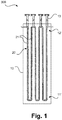
- Figure 1 schematically illustrates a reactor for carrying out a chemical reaction according to an embodiment not according to the invention.
- the reactor designated here by 300 is set up to carry out a chemical reaction.
- it has an in particular thermally insulated reactor vessel 10 and a reaction tube 20, a number of tube sections of the reaction tube 20, which are designated here by 21 only in two cases, each between a first zone 11 'and a second zone 12' in the Reactor vessel 10 run.
- the reaction tube 20, which will be described below with reference to FIG Figure 2 is explained in more detail, fastened with suitable suspensions 13.
- the reactor vessel can be in a lower area in particular have a not illustrated furnace. It goes without saying that a plurality of reaction tubes can be provided here and below.
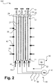
- Figure 2 schematically illustrates a reactor for carrying out a chemical reaction in accordance with an embodiment of the present invention, which is designated as a whole by 100.
- the zones previously designated 11 'and 12' are designed here as areas 11 and 12, with the pipe sections 21 for heating the pipe sections 21 in the first areas 11 each electrically connected to the phase connections U, V, W of a multiphase alternating current source 41 via connection elements 42 can be connected, whereby a total of 40 designated means for electrical heating of the reaction tube 20 are formed. Switches and the like and the specific type of connection are not illustrated.
- the pipe sections 21 are electrically conductively connected to one another in the second regions 12 by means of a connecting element 30 which is integrally connected to the one or more reaction tubes 20 and is arranged within the reactor vessel 10.
- a neutral conductor can also be connected to the connecting element 30.
- a star connection of several alternating current phases is implemented.
- the invention can also be provided using single-phase alternating current heating, direct current heating or other means of heating, for example for inductive or indirect heating in the sense explained above.
- a first group of reverse arcs 23 (bottom in the drawing) are arranged next to one another in the first area 11 and a second group of reverse arches 23 (top in the drawing) are arranged next to one another in the second area 12.
- the reverse arcs 23 of the second group are formed in the connecting element 30 and the pipe sections 21 extend from the connecting element 30 in the second area 12 to the first area 11.
- the power feed elements 52 can be designed as desired, for example rigid, and with rod-shaped sections through a wall of the Reactor container 10 step.
- Means for feeding an inerting gas into the reactor vessel are indicated by 50 in total. As illustrated by arrows 53 (only partially labeled accordingly), the inerting gas is fed into the reactor container 10 in particular via wall openings, nozzles or the like in one or more walls of the reactor container 10. To provide and feed in the inerting gas, suitable gas feed means are provided, which are also illustrated here in a greatly simplified manner and which comprise, for example, one or more gas tanks 51 and corresponding lines 52.
- Figure 3 schematically illustrates a reactor for carrying out a chemical reaction in accordance with an embodiment of the present invention, which is designated as a whole by 200.
- the pipe sections denoted here by 22 each comprise a pipe section 22 of a plurality of reaction tubes 20, the pipe sections 22 being fluidically unconnected next to one another in the reactor vessel 10 and each being connected to feed sections 24 and removal sections 25.
- connecting element 30 is optional within the scope of the present invention, although particularly advantageous when using a multiphase alternating current heater.
- power feed elements 42 are illustrated in a greatly simplified manner. The feeding of the inerting gas according to the arrows 53 takes place here as essentially explained above.
- the current feed elements 42 can have a collar-like area 43 attached to them, which in the first area 11 is placed around the reaction tubes 20 or the tube sections.
- the Figures 4 to 8 show partial views of reactors according to embodiments of the present invention in a simplified representation, a chimney 60 also being illustrated in each case.
- the gas feed means 50 for feeding in the inerting gas are not shown, nor are the means 40 for electrical heating.
- the reaction tube 20 is shown with reverse bends Figure 2 illustrated, but can also in any other form, for example according to Figure 3 be trained.
- a feed of inerting gas is indicated by an arrow 53 only at one point.
- the reactor vessel 10 has a permanently open outflow opening 61 connected to the chimney 60.
- the feed of inert gas and the high temperatures in the reactor vessel 10 opposite one end 63 of the chimney 60 results in a flow illustrated by arrows 64.
- the high temperatures lead to a static pressure p box in the reactor vessel, which is below atmospheric pressure p Atm in the adjacent environment, if the inerting gas is fed in in an adapted manner.
- the amount of purging gas chosen here is not too large. In the case of a very large amount of purging gas, the pressure loss in the chimney 60 would lead to the internal pressure in the reactor vessel 10 approaching or even exceeding the external pressure.
- this amount prevents ambient air from flowing back into the reactor vessel 10; In addition, minor air infiltration due to inadequate sealing is compensated for.
- the supply of inerting gas into the reactor vessel 10 can in particular be regulated via an oxygen measurement 65 in the chimney 60, so that the oxygen content can be kept constant during operation.
- the reactor vessel 10 according to Figure 5 operated at a pressure level above atmospheric, with a continuous feed of inerting gas into the reactor vessel 10 is made.
- the reactor vessel 10 has an opening above of a predetermined pressure level set up discharge opening 62, for example in the form of a bursting disc.
- the inerting gas supply compensates for small gas leaks into the atmosphere, which are illustrated here with an arrow 55.
- the flushing quantity can be regulated by measuring the pressure in the reactor vessel 10.
- a correspondingly dimensioned outlet opening to a safe place can be provided (in the area of the chimney 60 or another place that is not easily accessible and not endangering people) so that a flow 66 results from the reactor vessel 10.
- the reactor vessel 10 according to Figure 6 operated at a superatmospheric pressure level.
- the reactor vessel 10 has an outflow opening 62, for example in the form of a rupture disk, which is set up to open above a predetermined pressure level.
- the flow 66 does not develop in this embodiment.
- the oxygen content is preferably measured in the discharge of the purge gas downstream of the reactor container 10 (for example in the chimney 60 or another discharge line). Additionally or alternatively, the oxygen content can also be measured using suitable measuring methods (e.g. tunable diode laser, zirconium oxide probes, GC, paramagnet) be measured at one or more points in the area of the reactor vessel 10.
- suitable measuring methods e.g. tunable diode laser, zirconium oxide probes, GC, paramagnet
- the oxygen content can be measured analogously in a flushing gas discharge line that may be used for the initial inerting and / or in the reactor vessel 10 itself.
- the pressure inside the reactor vessel can be continuously measured and monitored in order to detect any impermissible loss of inert gas at an early stage.
- the chimney 60 in all of the configurations illustrated above can have structural elements (so-called velocity seals / confusors) in the area of the chimney wall in order to avoid air backflows (e.g. due to free convection currents) back to the reactor container 20.
- structural elements so-called velocity seals / confusors
- Figure 7 schematically illustrates a reactor for carrying out a chemical reaction according to an embodiment of the invention as an extension to the illustration according to the previous figures, with some of the elements already explained above not being illustrated again. For further explanation, reference is made in particular to the above Figure 4 referenced.
- ignition devices or pilot burners 68 can additionally be installed in the area of the chimney outlet 63 in order to at least partially prevent unburned hydrocarbons from escaping into the atmosphere in the event of an accident.
- the inerting gas can be fed into the reactor vessel 10 at different sides. A wall of the reactor vessel 10 and wall passages of fastenings or power supply devices are illustrated with 15, each of which can advantageously be made gas-tight. With I and O, process gas is fed in and the process gas is withdrawn from the reaction tube 20.
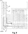
- FIG. 8 schematically illustrates a reactor for carrying out a chemical reaction according to an embodiment of the invention as an extension to the illustration according to FIG Figure 7 or a variant thereof.
- the chimney 60 can have suitable insulation 69 in an area adjoining the reactor vessel 10.
- the chimney 70 can have a height h of, for example, 20 to 50 meters above the ground.
- a so-called velocity seal 66 can be provided in the chimney 60.
- Figure 9 schematically illustrates the fundamentals of chimney dimensioning according to an embodiment of the present invention in the form of a diagram in which an oxygen content in percent is shown on the abscissa and a reaction-related rate of increase in volume in m 3 / s is shown on the ordinate.
- a graph 601 shows the relationship already explained above with reference to the table.
- a dashed line 602 denotes values required for a maximum pressure increase of 20 mbar with a chimney diameter of 500 mm
- a broken line 603 denotes corresponding values with a chimney diameter of 900 mm .
Landscapes
- Chemical & Material Sciences (AREA)
- Organic Chemistry (AREA)
- Chemical Kinetics & Catalysis (AREA)
- Health & Medical Sciences (AREA)
- General Health & Medical Sciences (AREA)
- Toxicology (AREA)
- Physical Or Chemical Processes And Apparatus (AREA)
- Devices And Processes Conducted In The Presence Of Fluids And Solid Particles (AREA)
Abstract
Die vorliegende Erfindung betrifft einen Reaktor (100, 200) zur Durchführung einer chemischen Reaktion, der einen Reaktorbehälter (10), ein oder mehrere Reaktionsrohre (20) und Mittel (40) zur elektrischen Beheizung des einen oder der mehreren Reaktionsrohre (20) aufweist. Der Reaktorbehälter (10) weist eine oder mehrere, dauerhaft geöffnete oder zur Öffnung oberhalb eines vorgegebenen Druckniveaus eingerichtete Ausströmöffnungen (61, 62) auf und es sind Gaseinspeisemittel (50) bereitgestellt, die dafür eingerichtet sind, in den Reaktorbehälter (10) ein Inertisierungsgas einzuspeisen. Ein entsprechendes Verfahren ist ebenfalls Gegenstand der vorliegenden Erfindung.The present invention relates to a reactor (100, 200) for carrying out a chemical reaction, which has a reactor container (10), one or more reaction tubes (20) and means (40) for electrically heating the one or more reaction tubes (20). The reactor container (10) has one or more outflow openings (61, 62) that are permanently open or that are set up to open above a predetermined pressure level, and gas feed means (50) are provided which are set up to feed an inerting gas into the reactor container (10) . A corresponding method is also the subject of the present invention.
Description
Die Erfindung betrifft einen Reaktor und ein Verfahren zur Durchführung einer chemischen Reaktion gemäß den Oberbegriffen der unabhängigen Patentansprüche.The invention relates to a reactor and a method for carrying out a chemical reaction according to the preambles of the independent claims.
In einer Reihe von Verfahren in der chemischen Industrie werden Reaktoren eingesetzt, in denen ein oder mehrere Reaktanden durch beheizte Reaktionsrohre geführt und dort katalytisch oder nichtkatalytisch umgesetzt werden. Die Beheizung dient dabei insbesondere dazu, die benötigte Aktivierungsenergie für die ablaufende chemische Reaktion zu überwinden. Die Reaktion kann insgesamt endotherm oder, nach Überwindung der Aktivierungsenergie, exotherm ablaufen. Die vorliegende Erfindung betrifft insbesondere stark endotherme Reaktionen.In a number of processes in the chemical industry, reactors are used in which one or more reactants are passed through heated reaction tubes and converted there catalytically or non-catalytically. The heating is used in particular to overcome the activation energy required for the chemical reaction that is taking place. The overall reaction can be endothermic or, after the activation energy has been overcome, exothermic. The present invention particularly relates to highly endothermic reactions.
Beispiele für solche Verfahren sind das Steamcracken (Dampfspalten), unterschiedliche Reformierungsverfahren, insbesondere die Dampfreformierung, die Trockenreformierung (Kohlendioxidreformierung), gemischte Reformierungsverfahren, Verfahren zur Dehydrierung von Alkanen und dergleichen. Beim Steamcracken werden die Reaktionsrohre dabei in Form von Rohrschlangen (engl. Coils), die im Reaktor zumindest einen Umkehrbogen aufweisen, durch den Reaktor geführt, wohingegen bei der Dampfreformierung typischerweise ohne Umkehrbogen durch den Reaktor verlaufende Rohre verwendet werden.Examples of such processes are steam cracking (steam cracking), various reforming processes, in particular steam reforming, dry reforming (carbon dioxide reforming), mixed reforming processes, processes for the dehydrogenation of alkanes and the like. In steam cracking, the reaction tubes are guided through the reactor in the form of coils, which have at least one reverse bend in the reactor, whereas in steam reforming tubes that run through the reactor without a reverse bend are typically used.
Die Erfindung eignet sich für alle derartigen Verfahren und Ausgestaltungen von Reaktionsohren. Rein illustrativ wird hier auf die Artikel "Ethylene", "Gas Production" und "Propene" in
Die Reaktionsrohre von entsprechenden Reaktoren werden herkömmlicherweise durch Verwendung von Brennern beheizt. Die Reaktionsrohre werden dabei durch eine Brennkammer geführt, in der auch die Brenner angeordnet sind.The reaction tubes of corresponding reactors are conventionally heated by using burners. The reaction tubes are guided through a combustion chamber in which the burners are also arranged.
Wie beispielsweise in der
Vor diesem Hintergrund wird in der erwähnten
Neben der direkten Beheizung von Reaktionsrohren, bei der ein elektrischer Strom durch die Reaktionsrohre fließt, existieren auch unterschiedlichste Konzepte für die indirekte elektrische Beheizung von Reaktionsrohren. Die indirekte elektrische Beheizung kann, wie unter anderem in der
Wie auch nachfolgend erläutert, sind bei elektrisch beheizten Reaktoren besondere sicherheitsrelevante Aspekte zu beachten. Die vorliegende Erfindung stellt sich die Aufgabe, Maßnahmen anzugeben, die diese Aspekte berücksichtigen und auf diese Weise einen vorteilhaften Betrieb eines elektrisch beheizten Reaktors erlauben.As also explained below, special safety-relevant aspects must be observed in the case of electrically heated reactors. The present invention has the task of specifying measures which take these aspects into account and in this way allow an advantageous operation of an electrically heated reactor.
Vor diesem Hintergrund schlägt die vorliegende Erfindung einen Reaktor und ein Verfahren zur Durchführung einer chemischen Reaktion gemäß den Oberbegriffen der unabhängigen Patentansprüche vor. Ausgestaltungen sind jeweils Gegenstand der abhängigen Patentansprüche sowie der nachfolgenden Beschreibung.Against this background, the present invention proposes a reactor and a method for carrying out a chemical reaction according to the preambles of the independent claims. Refinements are the subject matter of the dependent claims and the description below.
In einem elektrifizierten Ofenkonzept (der Begriff "Ofen" wird üblicherweise zur Bezeichnung eines entsprechenden Reaktors bzw. zumindest von dessen thermisch isoliertem Reaktionsraum verstanden), das der vorliegenden Erfindung zugrunde liegt, werden beispielsweise Reaktionsrohre bzw. entsprechende Rohrstrecken hiervon (nachfolgend auch kurz als "Rohre" bezeichnet) selbst als elektrische Widerstände benutzt, um Wärme zu erzeugen. Dieser direkte Ansatz hat den Vorteil eines höheren Wirkungsgrads im Vergleich zu einer indirekten Erwärmung durch externe elektrische Heizkörper sowie einer höheren erreichbaren Wärmestromdichte. Es ist aber, wie zuvor erwähnt, auch möglich, im Rahmen der vorliegenden Erfindung irgendeine andere Art der elektrischen Beheizung (direkt oder indirekt, als Widerstands-, Impedanz- oder Induktionsheizung, mittels ein- oder mehrphasigem Wechselstrom oder mit Gleichstrom) durchzuführen, wenn sich diese als vorteilhaft herausstellt.In an electrified furnace concept (the term "furnace" is usually understood to denote a corresponding reactor or at least its thermally insulated reaction space) on which the present invention is based, for example, reaction tubes or corresponding tube sections thereof (hereinafter also referred to as "tubes "referred to) themselves as electrical resistors used to generate heat. This direct approach has the advantage of a higher degree of efficiency compared to indirect heating by external electrical heating elements as well as a higher achievable heat flux density. However, as mentioned above, it is also possible within the scope of the present invention to use any other type of electrical heating (direct or indirect, as resistance, Impedance or induction heating, using single or multi-phase alternating current or direct current) if this proves to be advantageous.
Die Stromeinspeisung kann im Falle der Beheizung mit mehrphasigem Wechselstrom in die direkt beheizten Reaktionsrohre über M separat angeschlossene Phasen erfolgen. Die stromleitenden Reaktionsrohre, die mit den M Phasen verbunden sind, können an einen Sternpunkt am anderen Ende ebenfalls elektrisch verbunden werden. Die Phasenzahl M beträgt insbesondere 3, entsprechend der Phasenzahl üblicher Drehstromquellen bzw. -netze. Grundsätzlich ist die vorliegende Erfindung aber nicht auf die Verwendung von drei Phasen beschränkt, sondern kann auch mit einer größeren Phasenzahl, beispielsweise einer Phasenzahl von 4, 5, 6, 7 oder 8, verwendet werden. Ein Phasenversatz beträgt dabei insbesondere 360°/M, d.h. bei einem dreiphasigen Drehstrom 120°.In the case of heating with multiphase alternating current, the current can be fed into the directly heated reaction tubes via M separately connected phases. The current-conducting reaction tubes, which are connected to the M phases, can also be electrically connected to a star point at the other end. The number of phases M is in particular 3, corresponding to the number of phases of conventional three-phase current sources or networks. In principle, however, the present invention is not restricted to the use of three phases, but can also be used with a larger number of phases, for example a number of phases of 4, 5, 6, 7 or 8. A phase offset is particularly 360 ° / M, i.e. 120 ° for a three-phase alternating current.
Durch die Sternschaltung am Sternpunkt wird in einer elektrischen Beheizung mit mehrphasigem Wechselstrom ein Potentialausgleich zwischen den Phasen erreicht, was eine elektrische Isolierung der angeschlossenen Rohrleitungen idealerweise überflüssig macht. Dies stellt einen besonderen Vorteil eines derartigen Ofenkonzepts dar, da eine Unterbrechung der metallischen Reaktionsrohre zur Isolierung bestimmter Abschnitte insbesondere aufgrund der verwendeten hohen Temperaturen und des damit erforderlichen hohen Material- und Konstruktionsaufwands unerwünscht ist.Through the star connection at the star point, equipotential bonding is achieved between the phases in electrical heating with multiphase alternating current, which ideally makes electrical insulation of the connected pipelines superfluous. This represents a particular advantage of such a furnace concept, since an interruption of the metallic reaction tubes to isolate certain sections is undesirable, in particular because of the high temperatures used and the associated high expenditure on materials and construction.
Die nachfolgend erläuterten, erfindungsgemäß vorgeschlagenen Maßnahmen eignen sich jedoch in gleicher Weise für die Verwendung von einphasigem Wechselstrom und Gleichstrom und die vorliegende Erfindung kann sowohl in wechselstrom- als auch in gleichstrombeheizten Reaktoren oder auch in entsprechenden Mischformen zum Einsatz kommen. Wie erwähnt, eignet sich die vorliegende Erfindung auch zum Einsatz bei indirekt beheizten Reaktionsrohren. Bei einer Gleichstromanordnung ist beispielsweise gegenüber einer Wechselstromanordnung lediglich die Art der Stromquelle und der der Stromeinspeisung entgegengesetzte Bereich der Reaktionsrohre oder entsprechender strombeaufschlagter Abschnitte unterschiedlich. In letzterem wird eine elektrische Verbindung unterschiedlicher Rohrstrecken nur optional durchgeführt. Da in einer Gleichstromanordnung kein potentialfreier Sternpunkt vorliegt, sind geeignete Stromabfuhrelemente bereitzustellen, die den Stromfluss wieder sicher nach außen führen. Letztere können analog zu den nachfolgend noch beschriebenen Stromeinspeisungen ausgeführt werden.However, the measures proposed according to the invention explained below are equally suitable for the use of single-phase alternating current and direct current, and the present invention can be used both in alternating current and in direct current heated reactors or in corresponding mixed forms. As mentioned, the present invention is also suitable for use in indirectly heated reaction tubes. In the case of a direct current arrangement, for example, only the type of current source and the area of the reaction tubes or corresponding current-loaded sections opposite the current feed differ from an alternating current arrangement. In the latter, an electrical connection between different pipe sections is only carried out as an option. Since there is no potential-free star point in a direct current arrangement, suitable current discharge elements are to be provided that the Lead the current flow safely to the outside again. The latter can be implemented in the same way as the current feeds described below.
Die vorliegende Erfindung betrifft die Absicherung von elektrisch beheizten Reaktoren der erläuterten Art, die insbesondere für den Fall einer Beschädigung der Reaktionsrohre ("Coilreißer") erforderlich ist. Bei entsprechenden Beschädigungen können ein oder mehrere Reaktionsrohre insbesondere vollständig durchtrennt werden; die vorliegende Erfindung ist jedoch auch für Leckagen in geringerem Umfang vorteilhaft. Bei entsprechenden Beschädigungen kommt es zu einem schlagartigen oder schleichenden Austritt von brennbarem Gas in den aus Gründen der thermischen Isolierung weitgehend abgeschlossenen Reaktorbehälter.The present invention relates to the protection of electrically heated reactors of the type described, which is necessary in particular in the event of damage to the reaction tubes ("coil ruptures"). In the event of corresponding damage, one or more reaction tubes can in particular be severed completely; however, the present invention is also beneficial for minor leakages. In the event of corresponding damage, there is a sudden or gradual escape of combustible gas into the reactor vessel, which is largely closed for reasons of thermal insulation.
Derartige Beschädigungen sind in herkömmlichen, befeuerten Reaktoren ein geringeres sicherheitstechnisches Problem als in rein elektrisch beheizten Reaktoren, wie sie erfindungsgemäß insbesondere eingesetzt werden, da in befeuerten Reaktoren aus den Reaktionsrohren austretende brennbare Gase, beispielsweise in Form eines Kohlenwasserstoff-Dampf-Gemischs, durch die im Reaktorbehälter bzw. einer entsprechenden Brennkammer stattfindende Verbrennung sofort und kontinuierlich umgesetzt werden können, bzw. da durch die stattfindende Verbrennung ein deutlich reduzierter Sauerstoffgehalt vorliegt und damit der die Reaktionsrohre umgebende Gasraum bereits im Wesentlichen "inertisiert" ist. Dagegen könnten sich entsprechende brennbare Gase bei einer rein elektrischen Beheizung im Reaktorbehälter anreichern und dort bei dem normalen Sauerstoffgehalt der Luft und Temperaturen oberhalb der Selbstzündungstemperatur beispielsweise die Explosions- oder Detonationsgrenze erreichen. Auch bei einer Verbrennung ohne Explosion oder Detonation kommt es durch eine vollständige oder unvollständige Verbrennung zu einem Energieeintrag und damit ggf. zu einer Überhitzung. Die vollständige oder unvollständige Verbrennung kann zusammen mit dem aus den Reaktionsrohren ausströmenden Gasvolumen an sich insbesondere zu einer deutlichen Druckerhöhung führen. Die vorliegende Erfindung vermindert eine derartige Druckerhöhung, weil der Abbrand des Gasgemischs verhindert wird.Such damage is less of a safety problem in conventional, fired reactors than in purely electrically heated reactors, such as are used in particular according to the invention, since in fired reactors, flammable gases escaping from the reaction tubes, for example in the form of a hydrocarbon-steam mixture, are caused by the Reactor container or a corresponding combustion chamber can be implemented immediately and continuously, or since the combustion taking place has a significantly reduced oxygen content and thus the gas space surrounding the reaction tubes is already essentially "inerted". Corresponding flammable gases, on the other hand, could accumulate in the reactor vessel with purely electrical heating and, for example, reach the explosion or detonation limit there with the normal oxygen content of the air and temperatures above the auto-ignition temperature. Even in the case of a combustion without an explosion or detonation, complete or incomplete combustion leads to an input of energy and thus possibly to overheating. Complete or incomplete combustion, together with the volume of gas flowing out of the reaction tubes, can in particular lead to a significant increase in pressure. The present invention reduces such a pressure increase because the burn-up of the gas mixture is prevented.
Im Sprachgebrauch der Patentansprüche betrifft die vorliegende Erfindung dabei einen Reaktor zur Durchführung einer chemischen Reaktion, der einen Reaktorbehälter (d.h. einen thermisch isolierten oder zumindest teilweise isolierten Bereich), ein oder mehrere Reaktionsrohre und Mittel zur elektrischen Beheizung des einen oder der mehreren Reaktionsrohre aufweist. Der erfindungsgemäß vorgeschlagene Reaktor ist insbesondere zur Durchführung einer chemischen Reaktion auf einem im weiteren Verlauf für Hochtemperaturreaktionen erläuterten Temperaturniveau eingerichtet. Die Mittel zur elektrischen Beheizung können wie zuvor umfangreich erläutert ausgebildet sein. Es kann sich einerseits um Mittel zur Stromeinspeisung in das eine oder die mehreren Reaktionsrohre handeln, die einen Stromfluss in dem einen der oder den mehreren Reaktionsrohren und eine entsprechende Erwärmung bewirken, beispielsweise starre, in den Reaktor geführte Stromstäbe, aber auch um Mittel zur indirekten Beheizung wie Widerstands- und/oder induktive Heizeinrichtungen, die Wärme konduktiv und/oder durch Wärmestrahlung auf das eine oder die mehreren Reaktionsrohre übertragen oder die in dem einen oder mehreren Reaktionsrohren oder einer Katalysatorschüttung beispielsweise Wirbelströme erzeugen und auf diese Weise eine Erwärmung bewirken.In the parlance of the patent claims, the present invention relates to a reactor for carrying out a chemical reaction, which has a reactor vessel (ie a thermally insulated or at least partially insulated area), a or has a plurality of reaction tubes and means for electrically heating the one or more reaction tubes. The reactor proposed according to the invention is set up in particular to carry out a chemical reaction at a temperature level explained below for high-temperature reactions. The means for electrical heating can be designed as explained extensively above. On the one hand, it can be a means for feeding current into the one or more reaction tubes, which cause a current to flow in the one or more reaction tubes and a corresponding heating, for example rigid current rods guided into the reactor, but also means for indirect heating such as resistance and / or inductive heating devices that transfer heat conductively and / or by thermal radiation to the one or more reaction tubes or that generate eddy currents in the one or more reaction tubes or a catalyst bed, for example, and thus cause heating.
Im Rahmen der vorliegenden Erfindung weist der Reaktorbehälter eine oder mehrere, dauerhaft geöffnete oder zur Öffnung oberhalb eines vorgegebenen Druckniveaus eingerichtete Ausströmöffnungen auf, und es sind Gaseinspeisemittel bereitgestellt, die dafür eingerichtet sind, in den Reaktorbehälter ein Inertisierungsgas einzuspeisen.In the context of the present invention, the reactor vessel has one or more outflow openings that are permanently open or are set up to open above a predetermined pressure level, and gas feed means are provided which are set up to feed an inerting gas into the reactor vessel.
Nachfolgend wird überwiegend ein Reaktor beschrieben, der erfindungsgemäß bzw. gemäß unterschiedlichen Ausführungsformen der Erfindung ausgebildet ist. Die entsprechenden Erläuterungen gelten jeweils auch für ein entsprechendes Verfahren, bei dem die entsprechend eingerichteten Mittel jeweils die angegebenen Verfahrensschritte durchführen.In the following, a reactor is predominantly described which is designed according to the invention or according to different embodiments of the invention. The corresponding explanations also apply to a corresponding process in which the appropriately set up means carry out the specified process steps.
Zur Einspeisung des Inertisierungsgases umfassen die Gaseinspeisemittel beispielsweise Einspeisedüsen oder -öffnungen, die in den Reaktorbehälter münden sowie Leitungen und ein damit verbundenes Gasreservoir, wodurch der Innenraum des Reaktorbehälters mit dem Inertisierungsgas beaufschlagt werden kann. Der Reaktorbehälter ist insbesondere eine überwiegend, d.h. zu mindestens 90, 95 oder 99% von einer thermisch isolierenden Wand umgebene Kammer.To feed in the inerting gas, the gas feed means include, for example, feed nozzles or openings that open into the reactor vessel, as well as lines and a gas reservoir connected to them, whereby the interior of the reactor vessel can be charged with the inerting gas. The reactor vessel is in particular a chamber that is predominantly, i.e. at least 90, 95 or 99% surrounded by a thermally insulating wall.
Bei dem Inertisierungsgas kann es sich in allen Ausgestaltungen der vorliegenden Erfindung um ein Gas oder ein Gasgemisch handeln, das Stickstoff, Kohlendioxid und/oder Argon in einem jeweils überatmosphärischen Gehalt aufweist, bzw. sind die Gaseinspeisemittel zur Bereitstellung eines entsprechenden Inertisierungsgases eingerichtet, beispielsweise indem sie entsprechendes Inertisierungsgas vorhalten oder durch Mischung von Reingasen oder Zumischung von Reingasen zu Luft bereitstellen. Insbesondere kann der Gehalt an einem nicht brennbaren Gas bei mehr als 50%, 60%, 70%, 80% oder 90% liegen. Es muss sich bei einem Inertisierungsgas also nicht um ein reines "Inertgas" im klassisch verstandenen Sinne handeln; vielmehr reicht aus, wenn das Inertisierungsgas, insbesondere durch seinen Gehalt an einem nicht brennbaren Gas, den zündfähigen Mischungsbereich zumindest teilweise verringert, also die Gefahr einer Entzündung, Explosion oder Detonation reduziert. Ein Inertisierungsgas zur Verwendung im Rahmen der vorliegenden Erfindung kann insbesondere einen unteratmosphärischen Sauerstoffgehalt, beispielsweise einen Sauerstoffgehalt von weniger als 10%, 5%, 1%, 0,5% oder 0,1% aufweisen. Ein Inertisierungsgas kann insbesondere auch (vollständig oder im Wesentlichen) sauerstofffrei sein.In all embodiments of the present invention, the inerting gas can be a gas or a gas mixture, the nitrogen, carbon dioxide and / or argon in a superatmospheric content, or the gas feed means are set up to provide a corresponding inerting gas, for example by keeping the corresponding inerting gas available or by mixing clean gases or adding clean gases to air. In particular, the content of a non-combustible gas can be more than 50%, 60%, 70%, 80% or 90%. An inerting gas does not have to be a pure "inert gas" in the classically understood sense; Rather, it is sufficient if the inerting gas, in particular due to its content of a non-combustible gas, at least partially reduces the ignitable mixture area, that is to say reduces the risk of ignition, explosion or detonation. An inerting gas for use in the context of the present invention can in particular have a subatmospheric oxygen content, for example an oxygen content of less than 10%, 5%, 1%, 0.5% or 0.1%. An inerting gas can in particular also be (completely or essentially) free of oxygen.
Die vorliegende Erfindung schafft durch die vorgeschlagenen Maßnahmen ein Containment mit konditionierter Atmosphäre, dass für die thermische Isolierung und für die sicherheitstechnische Absicherung von Hochtemperaturreaktoren dient, bei denen der Energieeeintrag elektrisch erfolgt. Im Rahmen der vorliegenden Erfindung kann insbesondere eine vollständig elektrische Beheizung vorgesehen sein, d.h. die Beheizung der Reaktionsrohre erfolgt zumindest innerhalb des Reaktorbehälters vorteilhafterweise überwiegend oder ausschließlich durch thermische Beheizung, d.h. wenigstens 90, 95 oder 99% der hier eingebrachten Wärmemenge, insbesondere der gesamtem hier eingebrachten Wärmemenge, erfolgt durch elektrische Heizmittel. Ein Wärmeeintrag über ein durch das eine oder die mehreren Reaktionsrohre geführtes Gasgemisch bleibt hier unberücksichtigt, so dass sich dieser Anteil insbesondere auf die innerhalb des Reaktorbehälters von außen auf die Wand des einen oder der mehreren Reaktionsrohre übertragene oder innerhalb des Reaktorbehälters in der Wand oder einer Katalysatorschüttung erzeugte Wärme bezieht.By means of the proposed measures, the present invention creates a containment with a conditioned atmosphere that is used for thermal insulation and for the safety-related safeguarding of high-temperature reactors in which the energy input takes place electrically. In the context of the present invention, in particular, completely electrical heating can be provided, ie the heating of the reaction tubes takes place at least within the reactor vessel, advantageously predominantly or exclusively by thermal heating, ie at least 90, 95 or 99% of the amount of heat introduced here, in particular of the total amount of heat introduced here Amount of heat, takes place through electrical heating means. An input of heat via a gas mixture passed through the one or more reaction tubes is not taken into account here, so that this proportion is in particular transferred to the wall of the one or more reaction tubes inside the reactor container or inside the reactor container in the wall or a catalyst bed generated heat.
In seiner allgemeinsten Form beschreibt die Erfindung also ein Containment für mit Kohlenwasserstoffen beaufschlagte Hochtemperaturreaktoren (wobei eine Hochtemperaturreaktion hier insbesondere eine Reaktion bezeichnen soll, die auf einer Temperatur von mehr als 500 °C und insbesondere von 700 bis 1.000 °C abläuft) mit elektrischer Beheizung, das 1. in der Umgebung der Rohre eine inertisierte Atmosphäre bereitstellt, und 2. nicht dauerhaft fest verschlossen ist. Besonders bevorzugt ist die Anwendung für elektrisch beheizte Reaktoren, bei denen die Prozessgastemperatur nahe oder oberhalb der Selbstentzündungstemperatur der im Prozessgas enthaltenen Kohlenwasserstoffe liegt. Mit dem Begriff "Prozessgas" wird ein Gas oder Gasgemisch bezeichnet, das durch das eine oder die mehreren Reaktionsrohre strömt.In its most general form, the invention thus describes a containment for high-temperature reactors charged with hydrocarbons (a high-temperature reaction here in particular denotes a reaction which takes place at a temperature of more than 500 ° C. and in particular from 700 to 1,000 ° C.) electrical heating that 1. provides an inert atmosphere in the vicinity of the pipes, and 2. is not permanently closed. The use for electrically heated reactors in which the process gas temperature is close to or above the self-ignition temperature of the hydrocarbons contained in the process gas is particularly preferred. The term “process gas” denotes a gas or gas mixture which flows through the one or more reaction tubes.
Ausführungsformen der vorliegenden Erfindung unterscheiden sich insbesondere durch die Ausgestaltung der einen oder der mehreren, dauerhaft geöffneten oder zur Öffnung oberhalb eines vorgegebenen Druckniveaus eingerichteten Ausströmöffnungen. Auch eine Kombination entsprechend ausgestalteter Ausströmöffnungen ist jedoch grundsätzlich möglich.Embodiments of the present invention differ in particular in the design of the one or more outflow openings that are permanently open or that are set up to open above a predetermined pressure level. However, a combination of appropriately designed outflow openings is also possible in principle.
In einer nachfolgend als "erste Gruppe" bezeichneten Gruppe von Ausführungsformen ist oder sind die eine oder die mehreren Ausströmöffnungen dauerhaft geöffnet. Hiermit ist gemeint, dass die eine oder die mehreren Ausströmöffnungen dem Aus- oder Einströmen von Fluid in den bzw. aus dem Reaktorbehälter bis auf die ggf. vorhandene Verengung des Strömungsquerschnitts keinerlei mechanischen Widerstand entgegensetzt bzw. entgegensetzen. Die eine oder die mehreren Öffnungen ist bzw. sind also unverschlossen.In a group of embodiments referred to below as the “first group”, the one or more outflow openings is or are permanently open. This means that the one or more outflow openings do not oppose or oppose any mechanical resistance to the outflow or inflow of fluid into or out of the reactor vessel apart from the possibly existing narrowing of the flow cross-section. The one or more openings is or are therefore not closed.
In einer nachfolgend als "zweite Gruppe" bezeichneten Gruppe von Ausführungsformen ist oder sind die eine oder die mehreren Ausströmöffnungen dagegen für die Öffnung oberhalb des vorgegebenen Druckniveaus eingerichtet. Die eine oder die mehreren Ausströmöffnungen ist oder sind dabei unterhalb des vorgegebenen Druckniveaus verschlossen und ist oder sind für eine zeitweise oder dauerhafte Öffnung bei Erreichen des vorgegebenen Druckniveaus eingerichtet. Mit einer "dauerhaften" Öffnung wird dabei insbesondere eine irreversible Öffnung verstanden, so dass in dieser Ausgestaltung kein Wiederverschluss nach anschließender Unterschreitung des vorgegebenen Druckniveaus durch Ablassen von Gas erfolgt. Bei einer "zeitweisen" Öffnung erfolgt dagegen ein Wiederverschluss.In a group of embodiments referred to below as the “second group”, on the other hand, the one or more outflow openings is or are set up for the opening above the predetermined pressure level. The one or more outflow openings is or are closed below the predetermined pressure level and is or are set up for a temporary or permanent opening when the predetermined pressure level is reached. A "permanent" opening is understood to mean, in particular, an irreversible opening, so that in this embodiment there is no reclosure after the pressure level has subsequently fallen below the specified level by releasing gas. In the case of a "temporary" opening, on the other hand, a re-closure takes place.
Die eine oder die mehreren Ausströmöffnungen können zur Öffnung bei dem vorbestimmten Druckniveau beispielsweise eine oder mehrere feder- oder lastbeaufschlagte Klappen aufweisen, die einen durch die Feder- oder Lastkennwerte definierten Öffnungswiderstand aufweisen und sich daher erst ab einem entsprechenden Druck öffnen. In einer Ausgestaltung der zweiten Gruppe von Ausgestaltungen kann bzw. können auch eine oder mehrere Berstscheiben oder Überdruckventile an sich bekannter Art eingesetzt werden. Es ist auch möglich, einen Druckwert, beispielsweise sensorisch zu erfassen und bei Überschreiten eines vorgegebenen Schwellwerts einen Öffnungsmechanismus beliebiger Art, beispielsweise einen Zündmechanismus oder einen elektroaktorischen Antrieb, auszulösen. Dies ermöglicht es, im Bedarfsfall innerhalb einer kurzen Ansprechzeit einen ausreichend großen Querschnitt freizugeben, der im Normalbetrieb in der erläuterten Weise verschlossen gehalten wird.The one or more outflow openings can be, for example, one or more spring-loaded or spring-loaded for opening at the predetermined pressure level have load-acted flaps which have an opening resistance defined by the spring or load characteristics and therefore only open from a corresponding pressure. In one configuration of the second group of configurations, one or more bursting disks or pressure relief valves of a type known per se can also be used. It is also possible to detect a pressure value, for example by means of a sensor, and to trigger an opening mechanism of any type, for example an ignition mechanism or an electro-actuator drive, when a predetermined threshold value is exceeded. This makes it possible, if necessary, to release a sufficiently large cross section within a short response time, which cross section is kept closed in the manner explained during normal operation.
Insbesondere in der ersten Gruppe von Ausführungsformen, ggf. aber auch in der zweiten Gruppe von Ausgestaltungen kann der Reaktor für eine konstante Spülung mit Inertgas eingerichtet sein. Mit anderen Worten sind die erläuterten Gaseinspeisemittel dabei für eine kontinuierliche Einspeisung des Inertisierungsgases in den Reaktorbehälter eingerichtet. Das Inertisierungsgas kann dabei in der ersten Gruppe von Ausführungsformen insbesondere vorwiegend über die eine oder die mehreren dauerhaft geöffneten Ausströmöffnungen ausströmen, ggf. aber auch über weitere Ausströmöffnungen, insbesondere unvermeidbare oder gezielt geschaffene Gaslecks oder Bypässe, beispielsweise zu einem vorhandenen Kamin. In der zweiten Gruppe von Ausführungsformen, in der die eine oder die mehreren dauerhaft geöffneten Ausströmöffnungen im Normalfall verschlossen ist oder sind, sind für das Ausströmen des Inertisierungsgases entweder weitere Öffnungen vorgesehen, beispielsweise Bypassleitungen zu einem Kamin, oder unvermeidlich vorhanden, beispielsweise aufgrund von Undichtigkeiten des Reaktorbehälters.In particular in the first group of embodiments, but possibly also in the second group of configurations, the reactor can be set up for constant purging with inert gas. In other words, the gas feed means explained are set up for a continuous feed of the inerting gas into the reactor vessel. In the first group of embodiments, the inerting gas can in particular predominantly flow out via the one or more permanently open outflow openings, but possibly also via further outflow openings, in particular unavoidable or deliberately created gas leaks or bypasses, for example to an existing chimney. In the second group of embodiments, in which the one or more permanently open outflow openings is or are normally closed, either additional openings are provided for the outflow of the inerting gas, for example bypass lines to a chimney, or inevitably present, for example due to leaks in the Reactor vessel.
Alternativ zur konstanten Spülung kann jedoch auch vorgesehen sein, den Reaktor nur einmalig oder periodisch entsprechend einem oder mehrerer vorbestimmter Kriterien mit dem Inertisierungsgas zu beaufschlagen. Die Gaseinspeisemittel sind dann für einen derartigen Betrieb eingerichtet. Ein oder mehrere vorbestimmte Kriterien können beispielsweise ein Erreichen eines vorgegebenen Druckwerts und/oder einer vorgegebenen Konzentration, beispielsweise eines minimalen und tolerierbaren Sauerstoffgehalts, umfassen. Ein Kriterium kann aber auch sein, dass der Reaktorbehälter erstmalig in Betrieb genommen wird. Es kann insbesondere eine kontinuierliche Messung vorgenommen werden und die Einspeisung von Inertisierungsgas kann immer dann eingeleitet werden, wenn entsprechende Messwerte angeben, dass die vorgegebenen Kriterien nicht mehr erfüllt sind. Die einmalige oder periodische Beaufschlagung mit Inertisierungsgas kann insbesondere in der zweiten Gruppe von Ausführungsformen, unterhalb des Druckwerts für die Öffnung der einen oder der mehreren Ausströmöffnungen vorgesehen sein, da hier ein freies Abströmen des Inertisierungsgases verhindert und das Inertisierungsgas über längere Zeiträume in dem Reaktorbehälter gehalten werden kann.As an alternative to constant purging, however, provision can also be made to apply the inerting gas to the reactor only once or periodically in accordance with one or more predetermined criteria. The gas feed means are then set up for such an operation. One or more predetermined criteria can include, for example, reaching a predetermined pressure value and / or a predetermined concentration, for example a minimum and tolerable oxygen content. However, one criterion can also be that the reactor vessel is put into operation for the first time. In particular, it can be a continuous measurement can be carried out and the injection of inerting gas can always be initiated when corresponding measured values indicate that the specified criteria are no longer met. The one-time or periodic application of inerting gas can be provided, in particular in the second group of embodiments, below the pressure value for the opening of the one or more outflow openings, since here a free outflow of the inerting gas is prevented and the inerting gas is kept in the reactor vessel for longer periods of time can.
In einer besonders bevorzugten Ausgestaltung der ersten Gruppe von Ausführungsformen ist der Reaktor für einen Betrieb des Reaktorbehälters auf einem unteratmosphärischen Druckniveau eingerichtet. Hierbei sind Mittel zur Bildung einer Gasströmung aus dem Reaktor bereitgestellt. In diesem Zusammenhang kann oder können die eine oder die mehreren Ausströmöffnungen, die ja in dieser Gruppe von Ausführungsformen dauerhaft geöffnet ist bzw. sind, mit einem Kamin, der eine Kaminmündung in ausreichender Höhe aufweist, dauerhaft offen verbunden sein. Hierbei ergibt sich, aufgrund der hohen Temperaturen im Reaktorbehälter und der daraus resultierenden geringeren Dichte des enthaltenen Gasvolumens, ein statischer Unterdruck im Reaktorbehälter. Auch eine Verwendung von Gebläsen, beispielsweise bis zur Ausbildung eines entsprechenden statischen Unterdrucks, kann in diesem Zusammenhang vorgesehen sein.In a particularly preferred configuration of the first group of embodiments, the reactor is set up to operate the reactor vessel at a sub-atmospheric pressure level. Means for forming a gas flow out of the reactor are provided here. In this context, the one or more outflow openings, which is or are permanently open in this group of embodiments, can be connected to a chimney that has a chimney mouth at a sufficient height, permanently open. Due to the high temperatures in the reactor vessel and the resulting lower density of the gas volume contained, this results in a static negative pressure in the reactor vessel. The use of fans, for example until a corresponding static negative pressure is formed, can also be provided in this context.
In einer besonders bevorzugten Ausgestaltung der zweiten Gruppe von Ausführungsformen ist der Reaktor dagegen für einen Betrieb des Reaktorbehälters auf einem überatmosphärischen Druckniveau eingerichtet. Dies kann insbesondere dadurch erreicht werden, dass das Inertisierungsgas bis zu einem überatmosphärischen Druckniveau eingespeist wird, das unterhalb eines Öffnungsdrucks der Ausströmöffnungen liegt.In a particularly preferred configuration of the second group of embodiments, on the other hand, the reactor is set up for operation of the reactor vessel at a pressure level above atmospheric. This can be achieved in particular in that the inerting gas is fed in up to a pressure level above atmospheric which is below an opening pressure of the outflow openings.
Das bis zu einem gewissen Grad inertisierte und zur Umgebung "offene" System gemäß der ersten Gruppe an Ausführungsformen (insbesondere mit leichtem Unterdruck im Reaktorbehälter infolge des Kamineffekts) oder auch das "öffenbare" System gemäß der zweiten Gruppe von Ausführungsformen der vorliegenden Erfindung (das insbesondere mit einem gewissen Überdruck im Reaktorbehälter betrieben werden kann) kann die Drucksteigerungsrate im Fall eines Austritts von Kohlenwasserstoffen Beschädigung der Reaktionsrohre, auf ein tolerables und die Auslegungsgrenzen des Reaktorbehälters nicht verletzendes Maß begrenzen.The system, which has been inerted to a certain extent and is "open" to the environment, according to the first group of embodiments (in particular with a slight negative pressure in the reactor vessel as a result of the chimney effect) or also the "openable" system according to the second group of embodiments of the present invention (in particular can be operated with a certain overpressure in the reactor vessel) the rate of pressure increase in the event of an escape of Hydrocarbons Damage to the reaction tubes, limit to a tolerable level that does not violate the design limits of the reactor vessel.
Durch das Konzept eines mit Inertisierungsgas beaufschlagen Reaktorbehälters kann der dort vorliegende Sauerstoffgehalt reduziert werden. Die Umsetzungsrate der im Beschädigungsfall austretenden Kohlenwasserstoffe und damit die maßgebliche zusätzliche Volumenzunahme (in Folge des Reaktionswärmeeintrags) skaliert in erster Näherung mit dem Sauerstoffpartialdruck in der Box.The oxygen content present there can be reduced through the concept of a reactor vessel charged with inerting gas. The conversion rate of the hydrocarbons escaping in the event of damage and thus the significant additional increase in volume (as a result of the introduction of heat from the reaction) scales as a first approximation with the oxygen partial pressure in the box.
In beiden Gruppen von Ausführungsformen der vorliegenden Erfindung müssen durch die Einspeisung des Inertisierungsgases die Wände des Reaktorbehälter vorteilhafterweise nicht vollständig gasdicht ausgeführt werden, was aufgrund der hohen Temperaturen an bestimmten Stellen aufgrund einer erforderlichen Bewegungsmöglichkeit nur mit sehr hohem Materialaufwand, beispielsweise die Verwendung temperaturbeständiger Balgenstrukturen und dergleichen, durchzuführen wäre. Bei einem Betrieb auf unteratmosphärischen Druckniveau in Verbindung mit einem Kamin kann zwar ggf. über entsprechende Undichtigkeiten Luft in den Reaktorbehälter eingesaugt werden, diese wird jedoch durch die kontinuierliche, durch den Kamin bewirkte Strömung entsprechend abgeführt und verdünnt. Sicherheitsprobleme bei der Verwendung evtl. die Atmung behindernder Inertisierungsgase oder Komponenten hiervon können auf diese Weise verhindert werden. Bei einem Betrieb auf einem überatmosphärischen Druckniveau kann hingegen aufgrund der gleichmäßigen Druckausbreitung eine Einströmung von Luft in den Reaktorbehälter sicher verhindert werden. Über Lecks austretendes Inertisierungsgas kann beispielsweise durch eine ausreichende Belüftung außerhalb des Reaktorbehälters abgeführt bzw. verdünnt werden.In both groups of embodiments of the present invention, the feeding of the inerting gas means that the walls of the reactor vessel do not have to be made completely gas-tight, which, due to the high temperatures at certain points, requires a very high amount of material, for example the use of temperature-resistant bellows structures and the like to be carried out. When operating at a subatmospheric pressure level in connection with a chimney, air may possibly be sucked into the reactor vessel via corresponding leaks, but this is removed and diluted accordingly by the continuous flow caused by the chimney. Safety problems when using inerting gases or components thereof that may impede breathing can be prevented in this way. In the case of operation at a pressure level above atmospheric, on the other hand, an inflow of air into the reactor vessel can be reliably prevented due to the uniform pressure distribution. Inerting gas escaping via leaks can, for example, be discharged or diluted by adequate ventilation outside the reactor vessel.
Durch das vorgeschlagene Konzept des mit Inertisierungsgas beaufschlagten Reaktorbehälters kann der Sauerstoffgehalt hier reduziert werden. Wie erfindungsgemäß ausgenutzt werden kann, korreliert dabei die Umsetzungsrate der austretenden Kohlenwasserstoffe und damit die maßgebliche zusätzliche Volumenzunahmerate (in Folge des Reaktionswärmeeintrags) in erster Näherung mit dem Sauerstoffpartialdruck. Diese Korrelation ist in der nachfolgenden Tabelle 1 zusammengefasst, wobei mit γO2 der Sauerstoffpartialdruck und mit Vreak die reaktionsbedingte Volumenzunahmerate bezeichnet sind.The proposed concept of the reactor vessel charged with inerting gas enables the oxygen content to be reduced here. As can be used according to the invention, the conversion rate of the exiting hydrocarbons and thus the relevant additional rate of increase in volume (as a result of the introduction of heat of reaction) correlates to a first approximation with the oxygen partial pressure. This correlation is summarized in Table 1 below, with γO 2 denoting the oxygen partial pressure and V reak denoting the rate of increase in volume caused by the reaction.
Die Gaseinspeisemittel sind daher vorteilhafterweise dafür eingerichtet, einen Maximalsauerstoffgehalt in dem Reaktionsbehälter auf Grundlage einer Dimensionierung des oder der Kamine einzustellen.
Der maximal zulässige Druck pmax folgt aus der mechanischen Stabilität der jeweiligen Kammern bzw. eines umgebenden Containments. Dieser muss zumindest so groß sein, wie der Druck pbox bei einem Coilreißer oder bei einem entsprechenden anderen sicherheitsrelevanten Ereignis, welcher wiederum vom Volumen VBox der beteiligten Kammern, dem Kamindurchmesser DKamin und dem Sauerstoffpartialdruck abhängt: ![]()
![]()
Aus dieser Forderung ergibt sich eine Designgrundlage für die Dimensionierung des Kamins, also der über die eine oder die mehreren Ausströmöffnungen dauerhaft oder temporär vorhandenen Verbindung zur Umgebung und umgekehrt. Diese Beziehung wird nun anhand der
Je kleiner der Sauerstoffgehalt in dem Reaktorbehälter, desto geringer ist also die Volumenzunahme. Demzufolge kann auch der Durchmesser des Notkamins kleiner sein, der das zusätzliche Volumen abführen muss. Entscheidend für eine effiziente Begrenzung des Sauerstoffgehalts ist dabei stets eine hinreichend gute Abdichtung gegenüber der Umgebung, um den Eintrag von sauerstoffhaltiger Falschluft so weit wie möglich bzw. in ausreichender Weise zu verhindern. Wie erläutert, ist dabei jedoch keine vollständige Abdichtung erforderlich.The lower the oxygen content in the reactor vessel, the lower the increase in volume. As a result, the diameter of the emergency chimney, which has to dissipate the additional volume, can also be smaller. For an efficient limitation of the oxygen content, a sufficiently good seal against the environment is always decisive in order to prevent the entry of oxygen-containing false air as far as possible or in a sufficient manner. As explained, however, a complete seal is not required.
Mit anderen Worten wird im Rahmen der vorliegenden Erfindung also mittels des Inertisierungsgases ein Maximalsauerstoffgehalt in dem Reaktionsbehälter und/oder der Anschlusskammer eingestellt, der in der ersten Gruppe von Ausgestaltungen bei Vorhandensein eines Kamins auf Grundlage einer Dimensionierung des oder der Kamine ausgewählt wird, bzw. sind die Gaseinspeisemittel für eine Einspeisung von Inertisierungsgas bzw. für eine Einstellung des Sauerstoffgehaltes auf dieser Grundlage eingerichtet. Die Gaseinspeisemittel können auch insbesondere dafür eingerichtet sein, eine Einspeisung derart vorzunehmen, dass ein Zieldruck nicht überschritten wird. In der zweiten Gruppe von Ausführungsformen kann ebenfalls eine Einspeisung auf Grundlage einer Sauerstoffkonzentration bzw. eines Zieldrucks und einer Kamindimensionierung erfolgen.In other words, within the scope of the present invention, the inerting gas is used to set a maximum oxygen content in the reaction container and / or the connection chamber, which is or are selected in the first group of configurations when a chimney is present on the basis of a dimensioning of the chimney or chimneys the gas feed means are set up for feeding in inerting gas or for setting the oxygen content on this basis. The gas feed means can also be set up, in particular, to feed in in such a way that a target pressure is not exceeded. In the second group of embodiments, a feed can also take place on the basis of an oxygen concentration or a target pressure and a chimney dimensioning.
Eine Menge des eingespeisten Inertisierungsgases kann durch entsprechende Regelungsmittel insbesondere auf Grundlage einer Sauerstoffmessung in dem Reaktorbehälter oder in dem Kamin, falls vorhanden, geregelt werden, wodurch der Sauerstoffgehalt im Betrieb konstant gehalten werden kann. Ein entsprechendes Sicherheitskonzept kann beispielsweise auch umfassen, dass ein Betrieb des Reaktors unterbunden wird oder bleibt, wenn der gemessene Sauerstoffgehalt einen Sollsauerstoffgehalt überschreitet. Beispielsweise kann eine Einspeisung von Kohlenwasserstoffen in die Reaktionsohre und/oder deren Beheizung erst bei Unterschreitung eines geforderten Sauerstoffgehalts freigegeben werden. Bei Detektion eines Fehlers kann allgemein Reaktionsbetrieb mit Kohlenwasserstoffzugabe in die Reaktionsrohre unterbunden werden.A quantity of the inerting gas fed in can be regulated by appropriate regulating means, in particular on the basis of an oxygen measurement in the reactor vessel or in the chimney, if present, whereby the oxygen content can be kept constant during operation. A corresponding safety concept can also include, for example, that an operation of the reactor is prevented or remains if the measured oxygen content exceeds a target oxygen content. For example, a feed of hydrocarbons into the reaction tubes and / or their heating can only take place at If the oxygen content falls below the required level, they can be released. When a fault is detected, reaction operation can generally be prevented by adding hydrocarbons to the reaction tubes.
Ein unzulässiger Austritt von Gas aus den Reaktionsrohren kann beispielsweise über Druckmesssensoren detektiert werden, wobei eine Einspeisung von Kohlenwasserstoffen in die Reaktionsrohre bei Detektion eines Gasaustritts unterbunden werden kann, um die Gesamtmenge an austretenden Kohlenwasserstoffen zu minimieren.An impermissible escape of gas from the reaction tubes can be detected, for example, by means of pressure measuring sensors, whereby a feed of hydrocarbons into the reaction tubes can be prevented when a gas escape is detected in order to minimize the total amount of escaping hydrocarbons.
Zur Detektion sehr kleiner Beschädigungen (Leckströmung ohne drastischen Druckanstieg) kann auch der Kohlenwasserstoffgehalt in dem Reaktorbehälter oder dem Kamin, falls vorhanden (beispielsweise in Form eines Kohlenmonoxidäquivalents), kontinuierlich gemessen werden. Ein unzulässiger Wert kann ebenfalls die Unterbindung der Kohlenwasserstoffeinspeisung zur Folge haben.To detect very minor damage (leakage flow without a drastic increase in pressure), the hydrocarbon content in the reactor vessel or the chimney, if present (for example in the form of a carbon monoxide equivalent), can also be measured continuously. An inadmissible value can also prevent the hydrocarbon feed.
Die vorliegende Erfindung kann also, allgemeiner gesprochen, umfassen, dass auf Grundlage einer Druck- und/oder Kohlenwasserstoffmessung ein Wert bestimmt wird, der einen Gasaustritt aus dem einen oder den mehreren Reaktionsrohren kennzeichnet, und dass eine oder mehrere Sicherheitsmaßnahmen eingeleitet wird oder werden, wenn der Wert einen vorgegebenen Schwellwert überschreitet.The present invention can therefore, more generally speaking, include that on the basis of a pressure and / or hydrocarbon measurement, a value is determined which characterizes a gas exit from the one or more reaction tubes, and that one or more safety measures are or are initiated if the value exceeds a specified threshold.
Bei dem erfindungsgemäß vorgeschlagenen Verfahren zur Durchführung einer chemischen Reaktion wird ein Reaktor verwendet, der einen Reaktorbehälter, ein oder mehrere Reaktionsrohre und Mittel zur elektrischen Beheizung des einen oder der mehreren Reaktionsrohre aufweist. Erfindungsgemäß wird als der Reaktorbehälter ein Reaktorbehälter verwendet, der eine oder mehrere, dauerhaft geöffnete oder zur Öffnung oberhalb eines vorgegebenen Druckniveaus eingerichtete Ausströmöffnungen aufweist, und unter Verwendung von Gaseinspeisemitteln wird in den Reaktorbehälter erfindungsgemäß ein Inertisierungsgas eingespeist.In the method proposed according to the invention for carrying out a chemical reaction, a reactor is used which has a reactor vessel, one or more reaction tubes and means for electrically heating the one or more reaction tubes. According to the invention, a reactor container is used as the reactor container, which has one or more outflow openings that are permanently open or are set up to open above a predetermined pressure level, and an inerting gas is fed into the reactor container according to the invention using gas feed means.
Zu weiteren Merkmalen und Vorteilen eines entsprechenden Verfahrens, bei dem vorteilhafterweise ein Reaktor gemäß einer der zuvor erläuterten Ausgestaltungen der Erfindung verwendet wird, sei auf die obigen Erläuterungen verwiesen.For further features and advantages of a corresponding process in which a reactor according to one of the previously explained embodiments of the invention is advantageously used, reference is made to the above explanations.
Die Erfindung wird nachfolgend unter Bezugnahme auf die beigefügten Zeichnungen weiter erläutert, die Ausgestaltungen der vorliegenden Erfindung unter Bezugnahme und im Vergleich zum Stand der Technik veranschaulichen.The invention is explained further below with reference to the accompanying drawings, which illustrate embodiments of the present invention with reference to and in comparison with the prior art.
-
Figur 1 veranschaulicht schematisch einen Reaktor zur Durchführung einer chemischen Reaktion gemäß einer nicht erfindungsgemäßen Ausgestaltung.Figure 1 schematically illustrates a reactor for carrying out a chemical reaction according to an embodiment not according to the invention. -
Figuren 2 bis 8 veranschaulichen schematisch Reaktoren zur Durchführung einer chemischen Reaktion gemäß einer Ausgestaltung der Erfindung.Figures 2 to 8 schematically illustrate reactors for carrying out a chemical reaction according to an embodiment of the invention. -
Figur 9 veranschaulicht schematisch Grundlagen einer Kamindimensionierung gemäß einer Ausgestaltung der vorliegenden Erfindung.Figure 9 schematically illustrates the principles of chimney dimensioning according to an embodiment of the present invention.
In den Figuren sind einander baulich oder funktionell entsprechende Elemente mit identischen Bezugszeichen veranschaulicht und werden der Übersichtlichkeit halber nicht wiederholt erläutert. Werden nachfolgend Komponenten von Vorrichtungen erläutert, betreffen die entsprechenden Erläuterungen jeweils auch die damit durchgeführten Verfahren und umgekehrt. Die Figurenbeschreibung nimmt dabei wiederholt auf eine Wechselstrombeheizung Bezug. Wie erwähnt, eignet sich die vorliegende Erfindung aber in gleicher Weise auch zur Verwendung von Gleichstrom zur Beheizung. Auf die obigen Erläuterungen wird dabei verwiesen.In the figures, structurally or functionally corresponding elements are illustrated with identical reference symbols and are not explained repeatedly for the sake of clarity. If components of devices are explained below, the corresponding explanations also relate to the methods carried out with them and vice versa. The description of the figures makes repeated reference to AC heating. As mentioned, the present invention is equally suitable for using direct current for heating. Reference is made to the explanations above.
Der hier mit 300 bezeichnete Reaktor ist zur Durchführung einer chemischen Reaktion eingerichtet. Er weist dazu einen insbesondere thermisch isolierten Reaktorbehälter 10 und ein Reaktionsrohr 20 auf, wobei eine Anzahl von Rohrstrecken des Reaktionsrohrs 20, die hier nur in zwei Fällen mit 21 bezeichnet sind, jeweils zwischen einer ersten Zone 11' und einer zweiten Zone 12' in dem Reaktorbehälter 10 verlaufen. An einer Decke des Reaktorbehälters bzw. an einer Stützstruktur ist das Reaktionsrohr 20, das nachfolgend noch in Bezug auf
Die zuvor mit 11' und 12' bezeichneten Zonen sind hier als Bereiche 11 und 12 ausgebildet, wobei die Rohrstrecken 21 zur Beheizung der Rohrstrecken 21 in den ersten Bereichen 11 jeweils über Anschlusselemente 42 elektrisch mit den Phasenanschlüssen U, V, W einer mehrphasigen Wechselstromquelle 41 verbindbar sind, wodurch insgesamt mit 40 bezeichnete Mittel zur elektrischen Beheizung des Reaktionsrohrs 20 gebildet sind. Schalter und dergleichen sowie die spezifische Art der Anbindung sind nicht veranschaulicht. Die Rohrstrecken 21 sind in der hier veranschaulichten Ausgestaltung der Erfindung in den zweiten Bereichen 12 mittels eines Verbindungselements 30, das einstückig mit dem einen oder den mehreren Reaktionsrohren 20 verbunden und innerhalb des Reaktorbehälters 10 angeordnet ist, elektrisch leitend miteinander verbunden. An das Verbindungselement 30 kann auch ein Neutralleiter angebunden sein.The zones previously designated 11 'and 12' are designed here as
In dem hier veranschaulichten Beispiel wird also eine Sternschaltung mehrerer Wechselstromphasen realisiert. Wie mehrfach erwähnt, kann die Erfindung aber auch unter Verwendung einer einphasigen Wechselstromheizung, einer Gleichstromheizung oder anderer Mittel zur Beheizung, beispielsweise zur induktiven oder indirekten Beheizung im oben erläuterten Sinn, vorgesehen sein.In the example illustrated here, a star connection of several alternating current phases is implemented. As mentioned several times, the invention can also be provided using single-phase alternating current heating, direct current heating or other means of heating, for example for inductive or indirect heating in the sense explained above.
In dem hier veranschaulichten Reaktor 100 sind damit mehrere Rohrstrecken 21 eines Reaktionsrohrs 20 (wenngleich mehrere solcher Reaktionsrohre 20 bereitgestellt sein können), nebeneinander in dem Reaktorbehälter 10 angeordnet. Die Rohrstrecken 21 gehen über Umkehrbögen 23 (nur teilweise bezeichnet) ineinander über und sind mit einem Einspeiseabschnitt 24 und einem Entnahmeabschnitt 25 verbunden.In the
Eine erste Gruppe der Umkehrbögen 23 (in der Zeichnung unten) ist nebeneinander in dem ersten Bereich 11 und eine zweite Gruppe der Umkehrbögen 23 (in der Zeichnung oben) ist nebeneinander in dem zweiten Bereich 12 angeordnet. Die Umkehrbögen 23 der zweiten Gruppe sind in dem Verbindungselement 30 ausgebildet und die Rohrstrecken 21 erstrecken sich ausgehend von dem Verbindungselement 30 in dem zweiten Bereich 12 zu dem ersten Bereich 11. Die Stromeinspeiseelemente 52 können beliebig, beispielsweise starr, ausgebildet sein und mit stabförmigen Abschnitten durch eine Wand des Reaktorbehälters 10 treten.A first group of reverse arcs 23 (bottom in the drawing) are arranged next to one another in the
Mittel zur Einspeisung eines Inertisierungsgases in den Reaktorbehälter sind insgesamt mit 50 angegeben. Wie mit Pfeilen 53 (nur teilweise entsprechend bezeichnet) veranschaulicht, wird das Inertisierungsgas insbesondere über Wandöffnungen, Düsen oder dergleichen in einer oder mehreren beliebigen Wänden des Reaktorbehälters 10 in den Reaktorbehälter 10 eingespeist. Zur Bereitstellung und Einspeisung des Inertisierungsgases sind geeignete Gaseinspeisemittel vorgesehen, die hier stark vereinfacht mit veranschaulicht sind, und die beispielsweise einen oder mehrere Gastanks 51 sowie entsprechende Leitungen 52 umfassen.Means for feeding an inerting gas into the reactor vessel are indicated by 50 in total. As illustrated by arrows 53 (only partially labeled accordingly), the inerting gas is fed into the
In dem Reaktor 200 umfassen die hier abweichend mit 22 bezeichneten Rohrstrecken jeweils eine Rohrstrecke 22 von mehreren Reaktionsrohren 20, wobei die Rohrstrecken fluidisch 22 unverbunden nebeneinander in dem Reaktorbehälter 10 angeordnet sind und jeweils mit Einspeiseabschnitten 24 und Entnahmeabschnitten 25 verbunden sind. Zu den übrigen Elementen sei auf die obigen Erläuterungen zu den voranstehenden Figuren ausdrücklich verwiesen.In the
Wiederum ist die Verwendung eines Verbindungselements 30 im Rahmen der vorliegenden Erfindung optional, wenngleich insbesondere bei einer Verwendung einer mehrphasigen Wechselstromheizung vorteilhaft. Auch hier sind Stromeinspeiseelemente 42 stark vereinfacht veranschaulicht. Die Einspeisung des Inertisierungsgases entsprechend den Pfeilen 53 erfolgt hier wie im Wesentlichen zuvor erläutert. Die Stromeinspeiseelemente 42 können einen daran angebrachten manschettenartigen Bereich 43 aufweisen, der in dem ersten Bereich 11 um die Reaktionsrohre 20 bzw. die Rohrstrecken gelegt ist.Again, the use of a connecting
Die
Wie in
Bei dieser Ausführungsform mit Unterdruck in dem Reaktorbehälter verhindert diese Menge, dass es zu einer Rückströmung von Umgebungsluft in den Reaktorbehälter 10 kommt; zudem werden geringe Falschlufteinträge infolge unzureichender Abdichtung kompensiert. Die Inertisierungsgaszuführung in den Reaktorbehälter 10 kann insbesondere über eine Sauerstoffmessung 65 im Kamin 60 geregelt werden, so dass der Sauerstoffgehalt im Betrieb konstant gehalten werden kann.In this embodiment with negative pressure in the reactor vessel, this amount prevents ambient air from flowing back into the
Im Gegensatz zu der Ausgestaltung gemäß
Bei dieser alternativen Ausführung mit Überdruckbetrieb kompensiert die Inertisierungsgaszuführung geringe Gasleckagen in die Atmosphäre, die hier mit einem Pfeil 55 veranschaulicht sind. Die Regelung der Spülmenge kann in diesem Fall über eine Druckmessung in dem Reaktorbehälter 10 erfolgen. Für die kontinuierliche Inertisierungsgasspülung kann eine entsprechend dimensionierte Auslassöffnung zu einer sicheren Stelle vorgesehen sein (im Bereich des Kamins 60 oder einer anderen nicht einfach zugänglichen und nicht personengefährdenden Stelle), so dass sich ein Strom 66 aus dem Reaktorbehälter 10 ergibt.In this alternative embodiment with overpressure operation, the inerting gas supply compensates for small gas leaks into the atmosphere, which are illustrated here with an
Wie in der Ausgestaltung gemäß
In dieser alternativen Ausführung mit Überdruckbetrieb wird beispielsweise lediglich während der Betriebsvorbereitung eine Spülung zur Erstinertisierung vorgenommen. Im weiteren Betrieb wird kontinuierlich oder intervallweise lediglich die Ausgleichsmenge an Inertgas für die Leckageströme aus der dem Reaktorbehälter an die Atmosphäre hinzugeführt. Bei dieser Ausführung gibt es somit im Normalbetrieb keinen dauerhaft geöffneten Auslass für Inertgas an die Atmosphäre.In this alternative embodiment with overpressure operation, for example, flushing for initial inerting is only carried out during preparation for operation. During further operation, only the equalizing amount of inert gas for the leakage flows from the reactor vessel is fed into the atmosphere continuously or at intervals. In this design there is therefore no permanently open outlet for inert gas to the atmosphere in normal operation.
Ein Betrieb des Reaktors mit Kohlenwasserstoffen wird in den Ausgestaltungen gemäß den
Bei den Ausführungen gemäß
Wie in weiter untenstehenden detaillierteren Zeichnungen angedeutet, kann der Kamin 60 in allen zuvor veranschaulichten Ausgestaltungen insbesondere Im Bereich der Kaminwand konstruktive Elemente (sog. velocity seals/Confusor) zur Vermeidung von Luftrückströmungen (z.B. aufgrund freier Konvektionsströmungen) zurück zum Reaktorbehälter 20 aufweisen.As indicated in the more detailed drawings below, the
Wie hier veranschaulicht, können im Bereich des Kaminaustritts 63 zusätzlich Zündvorrichtungen oder Pilotbrenner 68 installiert werden, um im Havariefall den Austritt unverbrannter Kohlenwasserstoffe in die Atmosphäre zumindest teilweise zu unterbinden. Wie ferner veranschaulicht, kann das Inertisierungsgas an unterschiedlichen Seiten in den Reaktorbehälter 10 eingespeist werden. Mit 15 sind eine Wand des Reaktorbehälters 10 und Wanddurchtritte von Befestigungen oder Stromeinspeiseeinrichtungen veranschaulicht, die jeweils vorteilhafterweise gasdicht ausgebildet werden können. Mit I und O ist eine Einspeisung von Prozessgas und eine Entnahme des Prozessgases aus dem Reaktionsrohr 20 dargestellt.As illustrated here, ignition devices or
Wie hier veranschaulicht, kann der Kamin 60 in einem sich an den Reaktorbehälter 10 anschließenden Bereich eine geeignete Isolierung 69 aufweisen. Der Kamin 70 kann eine Höhe h von beispielsweise 20 bis 50 Metern über Grund aufweisen. Ein sogenanntes Velocity Seal 66 kann im Kamin 60 bereitgestellt sein.As illustrated here, the
Claims (15)
Priority Applications (11)
| Application Number | Priority Date | Filing Date | Title |
|---|---|---|---|
| EP20171196.7A EP3900818A1 (en) | 2020-04-23 | 2020-04-23 | Reactor and method for performing a chemical reaction |
| HUE21719925A HUE064114T2 (en) | 2020-04-23 | 2021-04-22 | Reactor and method for performing a chemical reaction |
| ES21719925T ES2967934T3 (en) | 2020-04-23 | 2021-04-22 | Reactor and method to carry out a chemical reaction |
| EP21719925.6A EP4139035B1 (en) | 2020-04-23 | 2021-04-22 | Reactor and method for performing a chemical reaction |
| CN202180030189.7A CN115427139A (en) | 2020-04-23 | 2021-04-22 | Reactor and method for carrying out chemical reactions |
| CA3179704A CA3179704A1 (en) | 2020-04-23 | 2021-04-22 | Reactor and method for carrying out a chemical reaction |
| JP2022564632A JP2023529785A (en) | 2020-04-23 | 2021-04-22 | Reactor and method for carrying out chemical reactions |
| PCT/EP2021/060601 WO2021214257A1 (en) | 2020-04-23 | 2021-04-22 | Reactor and method for carrying out a chemical reaction |
| US17/996,523 US20230211305A1 (en) | 2020-04-23 | 2021-04-22 | Reactor and Method for Carrying out a Chemical Reaction |
| KR1020227041127A KR20230010207A (en) | 2020-04-23 | 2021-04-22 | Reaction vessel and chemical reaction method |
| SA522441020A SA522441020B1 (en) | 2020-04-23 | 2022-10-23 | Reactor and method for carrying out a chemical reaction |
Applications Claiming Priority (1)
| Application Number | Priority Date | Filing Date | Title |
|---|---|---|---|
| EP20171196.7A EP3900818A1 (en) | 2020-04-23 | 2020-04-23 | Reactor and method for performing a chemical reaction |
Publications (1)
| Publication Number | Publication Date |
|---|---|
| EP3900818A1 true EP3900818A1 (en) | 2021-10-27 |
Family
ID=70470801
Family Applications (2)
| Application Number | Title | Priority Date | Filing Date |
|---|---|---|---|
| EP20171196.7A Withdrawn EP3900818A1 (en) | 2020-04-23 | 2020-04-23 | Reactor and method for performing a chemical reaction |
| EP21719925.6A Active EP4139035B1 (en) | 2020-04-23 | 2021-04-22 | Reactor and method for performing a chemical reaction |
Family Applications After (1)
| Application Number | Title | Priority Date | Filing Date |
|---|---|---|---|
| EP21719925.6A Active EP4139035B1 (en) | 2020-04-23 | 2021-04-22 | Reactor and method for performing a chemical reaction |
Country Status (10)
| Country | Link |
|---|---|
| US (1) | US20230211305A1 (en) |
| EP (2) | EP3900818A1 (en) |
| JP (1) | JP2023529785A (en) |
| KR (1) | KR20230010207A (en) |
| CN (1) | CN115427139A (en) |
| CA (1) | CA3179704A1 (en) |
| ES (1) | ES2967934T3 (en) |
| HU (1) | HUE064114T2 (en) |
| SA (1) | SA522441020B1 (en) |
| WO (1) | WO2021214257A1 (en) |
Families Citing this family (1)
| Publication number | Priority date | Publication date | Assignee | Title |
|---|---|---|---|---|
| EP4316638A1 (en) * | 2022-08-04 | 2024-02-07 | Linde GmbH | Method and installation for carrying out a gas phase reaction |
Citations (6)
| Publication number | Priority date | Publication date | Assignee | Title |
|---|---|---|---|---|
| WO2004091773A1 (en) * | 2003-04-15 | 2004-10-28 | Degussa Ag | Electrically heated reactor and process for carrying out gas reactions at a high temperature using this reactor |
| WO2015197181A1 (en) | 2014-06-26 | 2015-12-30 | Linde Aktiengesellschaft | Device and method for heating a fluid in a pipeline by means of three-phase current |
| EP3075704A1 (en) | 2015-03-31 | 2016-10-05 | Linde Aktiengesellschaft | Furnace with electrically heatable and fuel heatable reactor tubes for hydrocarbon steam reforming |
| WO2017072057A1 (en) | 2015-10-28 | 2017-05-04 | Haldor Topsøe A/S | Dehydrogenation of alkanes |
| WO2019228798A1 (en) | 2018-05-31 | 2019-12-05 | Haldor Topsøe A/S | Endothermic reactions heated by resistance heating |
| WO2020002326A1 (en) | 2018-06-29 | 2020-01-02 | Shell Internationale Research Maatschappij B.V. | Electrically heated reactor and a process for gas conversions using said reactor |
Family Cites Families (3)
| Publication number | Priority date | Publication date | Assignee | Title |
|---|---|---|---|---|
| PL175410B1 (en) | 1995-05-24 | 1998-12-31 | Karpinski Janusz | Apparatus for conducting processes at high temperatures and pressures |
| EP1043367B1 (en) | 1999-04-09 | 2003-01-15 | Jean Affolter | Method and plant for manufacturing carbon black |
| RU2173213C1 (en) | 2000-12-28 | 2001-09-10 | Зао "Тк Сибур Нн" | Gear for direct thermal conversion of methane |
-
2020
- 2020-04-23 EP EP20171196.7A patent/EP3900818A1/en not_active Withdrawn
-
2021
- 2021-04-22 HU HUE21719925A patent/HUE064114T2/en unknown
- 2021-04-22 ES ES21719925T patent/ES2967934T3/en active Active
- 2021-04-22 CN CN202180030189.7A patent/CN115427139A/en active Pending
- 2021-04-22 CA CA3179704A patent/CA3179704A1/en active Pending
- 2021-04-22 JP JP2022564632A patent/JP2023529785A/en active Pending
- 2021-04-22 KR KR1020227041127A patent/KR20230010207A/en active Search and Examination
- 2021-04-22 EP EP21719925.6A patent/EP4139035B1/en active Active
- 2021-04-22 WO PCT/EP2021/060601 patent/WO2021214257A1/en active Application Filing
- 2021-04-22 US US17/996,523 patent/US20230211305A1/en active Pending
-
2022
- 2022-10-23 SA SA522441020A patent/SA522441020B1/en unknown
Patent Citations (7)
| Publication number | Priority date | Publication date | Assignee | Title |
|---|---|---|---|---|
| WO2004091773A1 (en) * | 2003-04-15 | 2004-10-28 | Degussa Ag | Electrically heated reactor and process for carrying out gas reactions at a high temperature using this reactor |
| WO2015197181A1 (en) | 2014-06-26 | 2015-12-30 | Linde Aktiengesellschaft | Device and method for heating a fluid in a pipeline by means of three-phase current |
| EP3075704A1 (en) | 2015-03-31 | 2016-10-05 | Linde Aktiengesellschaft | Furnace with electrically heatable and fuel heatable reactor tubes for hydrocarbon steam reforming |
| DE102015004121A1 (en) | 2015-03-31 | 2016-10-06 | Linde Aktiengesellschaft | Oven with electric and fuel-heated reactor tubes for steam reforming of a hydrocarbon-containing insert |
| WO2017072057A1 (en) | 2015-10-28 | 2017-05-04 | Haldor Topsøe A/S | Dehydrogenation of alkanes |
| WO2019228798A1 (en) | 2018-05-31 | 2019-12-05 | Haldor Topsøe A/S | Endothermic reactions heated by resistance heating |
| WO2020002326A1 (en) | 2018-06-29 | 2020-01-02 | Shell Internationale Research Maatschappij B.V. | Electrically heated reactor and a process for gas conversions using said reactor |
Non-Patent Citations (1)
| Title |
|---|
| ULLMANN'S ENCYCLOPEDIA OF INDUSTRIAL CHEMISTRY, BEISPIELSWEISE DIE PUBLIKATIONEN VOM, 15 April 2009 (2009-04-15) |
Also Published As
| Publication number | Publication date |
|---|---|
| JP2023529785A (en) | 2023-07-12 |
| EP4139035A1 (en) | 2023-03-01 |
| KR20230010207A (en) | 2023-01-18 |
| WO2021214257A1 (en) | 2021-10-28 |
| CN115427139A (en) | 2022-12-02 |
| ES2967934T3 (en) | 2024-05-06 |
| SA522441020B1 (en) | 2024-04-16 |
| EP4139035B1 (en) | 2023-10-25 |
| US20230211305A1 (en) | 2023-07-06 |
| CA3179704A1 (en) | 2021-10-28 |
| HUE064114T2 (en) | 2024-02-28 |
Similar Documents
| Publication | Publication Date | Title |
|---|---|---|
| EP4139036B1 (en) | Reactor and method for performing a chemical reaction | |
| DE10317197A1 (en) | Electrically heated reactor and method for carrying out gas reactions at high temperature using this reactor | |
| DE2439144B2 (en) | Device for distributing flowing media from a flow cross-section to a different flow cross-section | |
| DE2513499A1 (en) | REFORMING OVEN WITH CONVECTION AND SYSTEM EQUIPPED WITH THIS OVEN | |
| EP4139035B1 (en) | Reactor and method for performing a chemical reaction | |
| WO2010063448A1 (en) | Device and method for catalytic gas phase reactions and use thereof | |
| DE60220608T2 (en) | fuel cell | |
| WO2021160777A1 (en) | Device and method for heating a fluid in a pipeline with single-phase alternating current | |
| EP4117811B1 (en) | Reactor and method for performing a chemical reaction | |
| EP1046174B1 (en) | Device for the catalytic conversion of hydrogen | |
| AT523668A1 (en) | Fuel cell system and method for operating a fuel cell system | |
| EP1118083A2 (en) | Device and method for recombining hydrogen and oxygen in a gaseous mixture | |
| DD288614A5 (en) | REACTOR FOR FLOW CURING | |
| DE20221983U1 (en) | Steam generator for generating water vapor, in particular ultrapure water vapor | |
| EP0056830A1 (en) | Hazard avoiding or diminishing method for an installation and its environment due to reacting mixtures | |
| DE102016110498B4 (en) | Microreactor and process control for methanation | |
| WO2010089323A2 (en) | Method for operating a coupling unit | |
| EP2486157B9 (en) | Method and hood-type annealing furnace for annealing metal bands at high temperatures | |
| DE19708738C1 (en) | Device for removing hydrogen | |
| DE102014007470A1 (en) | Process and apparatus for steam reforming and steam cracking of hydrocarbons | |
| DE69104546T2 (en) | Process for the thermal conversion of methane and device for carrying out the process. | |
| DE19513779A1 (en) | Catalytic cracking plant using electrostatic valves to control fine solids flow from reactor and regenerator | |
| DE855242C (en) | Oven for treating flowing reactants | |
| AT520881B1 (en) | Method for operating a fuel cell system | |
| DE102014018376A1 (en) | Method and device for introducing reactive gases into a reaction space |
Legal Events
| Date | Code | Title | Description |
|---|---|---|---|
| PUAI | Public reference made under article 153(3) epc to a published international application that has entered the european phase |
Free format text: ORIGINAL CODE: 0009012 |
|
| STAA | Information on the status of an ep patent application or granted ep patent |
Free format text: STATUS: THE APPLICATION HAS BEEN PUBLISHED |
|
| AK | Designated contracting states |
Kind code of ref document: A1 Designated state(s): AL AT BE BG CH CY CZ DE DK EE ES FI FR GB GR HR HU IE IS IT LI LT LU LV MC MK MT NL NO PL PT RO RS SE SI SK SM TR |
|
| B565 | Issuance of search results under rule 164(2) epc |
Effective date: 20200929 |
|
| STAA | Information on the status of an ep patent application or granted ep patent |
Free format text: STATUS: THE APPLICATION IS DEEMED TO BE WITHDRAWN |
|
| 18D | Application deemed to be withdrawn |
Effective date: 20220429 |