EP3900670A1 - Interdental cleaning tool - Google Patents
Interdental cleaning tool Download PDFInfo
- Publication number
- EP3900670A1 EP3900670A1 EP19904019.7A EP19904019A EP3900670A1 EP 3900670 A1 EP3900670 A1 EP 3900670A1 EP 19904019 A EP19904019 A EP 19904019A EP 3900670 A1 EP3900670 A1 EP 3900670A1
- Authority
- EP
- European Patent Office
- Prior art keywords
- section
- outer dimension
- cleaning tool
- interdental cleaning
- shaft section
- Prior art date
- Legal status (The legal status is an assumption and is not a legal conclusion. Google has not performed a legal analysis and makes no representation as to the accuracy of the status listed.)
- Withdrawn
Links
- 238000004140 cleaning Methods 0.000 title claims abstract description 46
- 239000000463 material Substances 0.000 claims abstract description 30
- 230000000694 effects Effects 0.000 abstract description 9
- 238000003780 insertion Methods 0.000 abstract description 7
- 230000037431 insertion Effects 0.000 abstract description 7
- 229920001971 elastomer Polymers 0.000 description 9
- 239000000806 elastomer Substances 0.000 description 9
- 229920003002 synthetic resin Polymers 0.000 description 6
- 239000000057 synthetic resin Substances 0.000 description 6
- 230000007704 transition Effects 0.000 description 6
- -1 polypropylene Polymers 0.000 description 4
- PPBRXRYQALVLMV-UHFFFAOYSA-N Styrene Chemical compound C=CC1=CC=CC=C1 PPBRXRYQALVLMV-UHFFFAOYSA-N 0.000 description 2
- XECAHXYUAAWDEL-UHFFFAOYSA-N acrylonitrile butadiene styrene Chemical compound C=CC=C.C=CC#N.C=CC1=CC=CC=C1 XECAHXYUAAWDEL-UHFFFAOYSA-N 0.000 description 2
- 229920000122 acrylonitrile butadiene styrene Polymers 0.000 description 2
- 239000004676 acrylonitrile butadiene styrene Substances 0.000 description 2
- 229920005989 resin Polymers 0.000 description 2
- 239000011347 resin Substances 0.000 description 2
- 229930182556 Polyacetal Natural products 0.000 description 1
- 239000004952 Polyamide Substances 0.000 description 1
- 239000004698 Polyethylene Substances 0.000 description 1
- 239000004743 Polypropylene Substances 0.000 description 1
- 239000004793 Polystyrene Substances 0.000 description 1
- 230000007423 decrease Effects 0.000 description 1
- 239000002657 fibrous material Substances 0.000 description 1
- 239000003365 glass fiber Substances 0.000 description 1
- 238000004519 manufacturing process Methods 0.000 description 1
- 229920002647 polyamide Polymers 0.000 description 1
- 229920001707 polybutylene terephthalate Polymers 0.000 description 1
- 229920000515 polycarbonate Polymers 0.000 description 1
- 239000004417 polycarbonate Substances 0.000 description 1
- 229920000728 polyester Polymers 0.000 description 1
- 229920000573 polyethylene Polymers 0.000 description 1
- 229920000139 polyethylene terephthalate Polymers 0.000 description 1
- 239000005020 polyethylene terephthalate Substances 0.000 description 1
- 229920006124 polyolefin elastomer Polymers 0.000 description 1
- 229920006324 polyoxymethylene Polymers 0.000 description 1
- 229920001155 polypropylene Polymers 0.000 description 1
- 229920001296 polysiloxane Polymers 0.000 description 1
- 229920002223 polystyrene Polymers 0.000 description 1
- 238000003825 pressing Methods 0.000 description 1
Images


Classifications
-
- A—HUMAN NECESSITIES
- A61—MEDICAL OR VETERINARY SCIENCE; HYGIENE
- A61C—DENTISTRY; APPARATUS OR METHODS FOR ORAL OR DENTAL HYGIENE
- A61C15/00—Devices for cleaning between the teeth
- A61C15/02—Toothpicks
-
- A—HUMAN NECESSITIES
- A46—BRUSHWARE
- A46B—BRUSHES
- A46B2200/00—Brushes characterized by their functions, uses or applications
- A46B2200/10—For human or animal care
- A46B2200/1066—Toothbrush for cleaning the teeth or dentures
- A46B2200/108—Inter-dental toothbrush, i.e. for cleaning interdental spaces specifically
Definitions
- the present invention relates to an interdental cleaning tool.
- Patent Document 1 discloses an interdental cleaning tool that includes a base material portion made of a synthetic resin and a soft portion made of an elastomer.
- the base material portion includes a flat handle section, which serves as a handle, and an elongated core base material section, which extends from the distal end of the handle section.
- the soft portion includes a covering section, which covers at least a part of the core base material section, and a plurality of projections, which extend from the surface of the covering section.
- Patent Document 1 WO 2013/176297
- the core base material section of an interdental cleaning tool is usually formed in a substantially conical (tapered) shape reducing in diameter toward the distal end thereof, and designed to allow cleaning of a certain range of interdental spaces ranging from relatively narrow to relatively wide spaces.
- the thick part of the core base material section designed for cleaning wide spaces between teeth has higher strength because of the thickness, hence, it has poor conformability to the interdental space, causing an issue that it is prone to break when forcibly inserted between the teeth.
- This issue occurs evidently, in particular, in a core base material section having a diameter (including the elastomer portion) of 1.5 mm or more, which is generally referred to as size L.
- This issue cannot be resolved simply by making the core base material section thinner because of users' need to thoroughly clean the space between teeth that is, in particular, relatively wide, by firmly pressing the tool with a strong shaft.
- an object of the present invention is to provide an interdental cleaning tool that achieves both easy insertion between teeth and improved cleaning effect.
- An interdental cleaning tool includes a base material portion including a base section and a shaft section extending from the base section; and a soft portion covering at least a part of the shaft section, wherein the at least the part of the shaft section has a first outer dimension defined in a first direction and a second outer dimension, defined in a second direction perpendicular to the first direction and smaller than the first outer dimension, in a cross section of the shaft section perpendicular to an axial direction of the shaft section.
- a cross section of at least the part of the shaft section has a first outer dimension defined in a first direction and a second outer dimension defined in a second direction perpendicular to the first direction and smaller than the first outer dimension. Consequently, the shaft section flexes more easily in the second direction of the second outer dimension which is smaller, while it does not flex as easily in the first direction of the first outer dimension. In other words, the shaft section has increased strength in the first direction. Therefore, easy insertion between the teeth can be realized through use of the interdental cleaning tool in a way that lets the tool flex in the second direction in which it can flex more easily.
- the cleaning effect can be increased through use of the interdental cleaning tool which is firmly pressed against the teeth in the first direction in which it flexes less easily, because this allows the soft portion to be pressed against the side faces of the teeth more firmly. Therefore, this interdental cleaning tool can achieve both easy insertion between teeth and improved cleaning effect.
- the first outer dimension is preferably defined in a direction parallel to a plane extending along the base section.
- the first outer dimension and the second outer dimension preferably have a ratio (second outer dimension/first outer dimension) of 0.20 to 0.98.
- the second outer dimension is preferably 1.0 mm or more.
- the soft portion preferably has a length, defined in an axial direction of the shaft section, of 15 mm or more.
- the first outer dimension and the second outer dimension may have a ratio (second outer dimension/first outer dimension) gradually increasing from a distal end section toward the base section of the shaft section.
- the present invention can provide an interdental cleaning tool that achieves both easy insertion between teeth and improved cleaning effect.
- the interdental cleaning tool 1 includes a base material portion 10, and a soft portion 20 covering at least part of the base material portion 10.
- the interdental cleaning tool 1 is individually cut off and separated from a connected member 40 of, for example, 10 interdental cleaning tools 1 joined together in parallel along a lateral direction (first direction) D1 of the interdental cleaning tool 1 by a pair of connecting sections 30, 30 formed, for example, on the base material portion 10.
- the base material portion 10 includes a base section 11 for a user to hold, and a shaft section 12 extending from the distal end of the base section 11 along a longitudinal direction D2 perpendicular to the lateral direction D1 of the interdental cleaning tool 1 to be inserted between the teeth of the user.
- the side toward the shaft section 12 as viewed from the base section 11 is referred to as the distal side
- the side toward the base section 11 as viewed from the shaft section 12 is referred to as the proximal side.
- the base section 11 is formed in a flat, wide plate-like shape, for example.
- it is formed in a flat cuboidal shape, but may be formed in other shapes as long as the user can hold it.
- the shaft section 12 extends from the distal end that is one end of the base section 11 along the longitudinal direction D2.
- the shaft section 12 includes a transition section 13 continuing from the base section 11 and extending in a flat plate-like shape, and a distal end section 14 extending from the distal end of the transition section 13 to the distal end of the shaft section 12 in a thin pin-like shape.
- the transition section 13 is formed in a tapered shape wherein the width defined along the lateral direction D1 is reduced toward the distal end of the shaft section 12.
- the base material portion 10 is molded from a synthetic resin material, for example.
- Synthetic resin materials that can be adopted include, for example, polypropylene, polyethylene, ABS (acrylonitrile butadiene styrene), polybutylene terephthalate, polycarbonate, polyethylene terephthalate, polystyrene, polyacetal, polyamide, and so on.
- the synthetic resin material may additionally contain a fiber material such as glass fiber in a ratio of about 1 to 30 weight%, for example.
- the soft portion 20 includes a covering section 21 that covers an outer circumferential surface of at least part of the distal end section 14 of the shaft section 12, and a plurality of projections 22 projecting from the covering section 21.
- the projections 22 are formed in a conical shape, for example, and arranged helically around the axis of the distal end section 14 of the shaft section 12 from the proximal end to the distal end of the covering section 21.
- the height of the projections 22 from the outer circumferential surface of the covering section 21 decreases from the proximal end to the distal end of the covering section 21.
- the soft portion 20 is made of a resin material having a lower hardness than that of the synthetic resin material of the base section 10.
- Elastomer can be adopted as the resin material.
- Applicable elastomers include styrene-based elastomer, silicone, olefin-based elastomer, polyester-based elastomer, and so on.
- the elastomer should preferably have a shore A durometer hardness (JISK6253) of 10 to 50, more preferably 10 to 40. In this embodiment, the elastomer has a shore A durometer hardness of 35.
- the base material portion 10 of the interdental cleaning tool 1 of this embodiment is designed to have a length L1 defined along the longitudinal direction D2 of 45 mm to 55 mm, for example.
- the base section 11 is designed to have a width W1 defined along the lateral direction D1 of 3 mm to 10 mm, for example.
- the base section 11 is designed to have a thickness T1 defined along a thickness direction (second direction) D3 perpendicular to the lateral direction D1 and longitudinal direction D2 of 0.5 mm to 10 mm, for example.
- the covering section 21 is designed to have a length defined along the longitudinal direction D2 from its proximal end to the distal end of 10 mm to 25 mm, for example.
- the covering section 21 is formed with a uniform thickness at the same position in the longitudinal direction D2, the thickness being 0.1 mm to 2.5 mm, for example.
- the projections 22 are designed to have a height from the outer circumferential surface of the covering section 21 of 0.1 mm to 5.0 mm, for example.
- the issue the present invention is meant to solve mentioned above is more prone to arise when the covering section 21 is longer, meaning, the longer the covering section, the more the effect of the invention is achieved.
- the length of the covering section 21 defined along the longitudinal direction D2 should preferably be 15 mm or more, more preferably 16 mm or more, and particularly preferably 18 mm or more.
- the distal end section 14 includes a distal end region 14a extending from the distal end toward the proximal end thereof, and a proximal end region 14b extending from the distal end region 14a to the transition section 13. At least part of the distal end region 14a is covered by the covering section 21. As shown in Fig. 4 , the distal end region 14a is designed to have a substantially true-circle cross section perpendicular to the axis of the shaft section 12.
- the distal end region 14a is formed in a tapered shape, radially reducing from the proximal end toward the distal end thereof, its diameter (i.e., first outer dimension X1 defined along the lateral direction D1, or second outer dimension X2 defined along the thickness direction D3) being 0.6 mm to 3.0 mm, for example.
- the distal end region 14a is designed to have a length from the distal end to the proximal end of the soft portion 20 of 15 mm, and the proximal end region 14b is similarly designed to have a length of 5 mm.
- the proximal end region 14b is designed to have a cross section whose first outer dimension X1 defined along the lateral direction D1 is larger than the second outer dimension X2 defined along the thickness direction D3 perpendicular to the lateral direction D1.
- the second outer dimension X2 of the proximal end region 14b should preferably be set to 1.0 mm or more, and more preferably 1.1 mm or more.
- the ratio between the first outer dimension X1 and the second outer dimension X2 (X2/X1) is set to 0.20 to 0.98, and may more preferably be 0.30 to 0.97.
- This ratio (X2/X1) may be set to increase gradually from a distal end section toward a base section of the proximal end region 14b.
- X1 denotes the relatively longer one of the first outer dimension X1 and the second outer dimension X2, i.e., the outer dimension along the lateral direction D1 need not necessarily be X1.
- the proximal end region is designed to have a cross-sectional shape that transforms to more rectangular from the distal end region 14b toward the transition section 12. For example, while the cross section in Fig. 5 near the distal end region 14b is substantially oval, it is more rectangular near the transition section 12.
- the interdental cleaning tool 1 described above allows its shaft section 12 to flex more easily in the thickness direction D3 along the second outer dimension X2, while not allowing the shaft section 12 to flex as easily in the lateral direction D1 along the first outer dimension X1, because of the second outer dimension X2 being smaller than the first outer dimension X1 in the proximal end region 14b of the shaft section 12.
- the shaft section 12 has increased strength in the lateral direction D1 as compared to the longitudinal direction D2. Therefore, easy insertion between the teeth can be realized through use of the interdental cleaning tool 1 in a way that lets the tool flex in the thickness direction D3 in which it can flex more easily.
- the cleaning effect can be increased through use of the interdental cleaning tool 1 in which it is firmly pressed against the teeth in the lateral direction D1 in which it flexes less easily, because this allows the covering section 21 and projections 22 to be pressed against the side faces of the teeth more firmly. Therefore, easy insertion between teeth and improved cleaning effect can both be achieved.
- the distal end region 14a located further toward the distal side of the shaft section 12 than the proximal end region 14b is designed to have a substantially true-circle cross section, so that the distal end region 14a can bend in any direction perpendicular to the axis of the shaft section 12. Therefore, in addition to the flexibility in the thickness direction D3 of the proximal end region 14b described above, the degree of bendability of the shaft section 12 when the interdental cleaning tool 1 is inserted between the teeth can further be increased.
- the filling space of a primary mold conforming to the outer shape of the base material portion 10 is filled with a molten synthetic resin material to mold the base material portion 10. After that, the base material portion 10 is taken out of the primary mold. Then, the molded base material portion 10 is arranged inside the filling space of a secondary mold conforming to the outer shape of the soft portion 20. The filling space is filled with a molten elastomer to mold the soft portion 20. Thus the interdental cleaning tool 1 is mold. After that, the interdental cleaning tool 1 is taken out of the secondary mold.
- the covering section 21 and projections 22 of the interdental cleaning tool 1 described above may cover not only the distal end region 14a but also the proximal end region 14b of the shaft section 12.
- the settings of the first outer dimension X1 and second outer dimension X2 may be applied not only to the proximal end region 14b but also to part or all of the distal end region 14a.
- the first outer dimension X1 may be set along the thickness direction D3, and the second outer dimension X2 smaller than the first outer dimension X1 may be set along the lateral direction D1.
Landscapes
- Health & Medical Sciences (AREA)
- Dentistry (AREA)
- Epidemiology (AREA)
- Life Sciences & Earth Sciences (AREA)
- Animal Behavior & Ethology (AREA)
- General Health & Medical Sciences (AREA)
- Public Health (AREA)
- Veterinary Medicine (AREA)
- Brushes (AREA)
Abstract
Description
- The present invention relates to an interdental cleaning tool.
- Conventionally, interdental cleaning tools for cleaning the spaces between the teeth are known. For example, Patent Document 1 discloses an interdental cleaning tool that includes a base material portion made of a synthetic resin and a soft portion made of an elastomer. The base material portion includes a flat handle section, which serves as a handle, and an elongated core base material section, which extends from the distal end of the handle section. The soft portion includes a covering section, which covers at least a part of the core base material section, and a plurality of projections, which extend from the surface of the covering section.
- Patent Document 1:
WO 2013/176297 - The core base material section of an interdental cleaning tool is usually formed in a substantially conical (tapered) shape reducing in diameter toward the distal end thereof, and designed to allow cleaning of a certain range of interdental spaces ranging from relatively narrow to relatively wide spaces. However, the thick part of the core base material section designed for cleaning wide spaces between teeth has higher strength because of the thickness, hence, it has poor conformability to the interdental space, causing an issue that it is prone to break when forcibly inserted between the teeth. This issue occurs evidently, in particular, in a core base material section having a diameter (including the elastomer portion) of 1.5 mm or more, which is generally referred to as size L. This issue cannot be resolved simply by making the core base material section thinner because of users' need to thoroughly clean the space between teeth that is, in particular, relatively wide, by firmly pressing the tool with a strong shaft.
- Accordingly, an object of the present invention is to provide an interdental cleaning tool that achieves both easy insertion between teeth and improved cleaning effect.
- An interdental cleaning tool according to one aspect of the present invention includes a base material portion including a base section and a shaft section extending from the base section; and a soft portion covering at least a part of the shaft section, wherein the at least the part of the shaft section has a first outer dimension defined in a first direction and a second outer dimension, defined in a second direction perpendicular to the first direction and smaller than the first outer dimension, in a cross section of the shaft section perpendicular to an axial direction of the shaft section.
- According to this aspect, a cross section of at least the part of the shaft section has a first outer dimension defined in a first direction and a second outer dimension defined in a second direction perpendicular to the first direction and smaller than the first outer dimension. Consequently, the shaft section flexes more easily in the second direction of the second outer dimension which is smaller, while it does not flex as easily in the first direction of the first outer dimension. In other words, the shaft section has increased strength in the first direction. Therefore, easy insertion between the teeth can be realized through use of the interdental cleaning tool in a way that lets the tool flex in the second direction in which it can flex more easily. On the other hand, the cleaning effect can be increased through use of the interdental cleaning tool which is firmly pressed against the teeth in the first direction in which it flexes less easily, because this allows the soft portion to be pressed against the side faces of the teeth more firmly. Therefore, this interdental cleaning tool can achieve both easy insertion between teeth and improved cleaning effect.
- In the aspect described above, the first outer dimension is preferably defined in a direction parallel to a plane extending along the base section. The first outer dimension and the second outer dimension preferably have a ratio (second outer dimension/first outer dimension) of 0.20 to 0.98. The second outer dimension is preferably 1.0 mm or more. Moreover, the soft portion preferably has a length, defined in an axial direction of the shaft section, of 15 mm or more. Additionally, the first outer dimension and the second outer dimension may have a ratio (second outer dimension/first outer dimension) gradually increasing from a distal end section toward the base section of the shaft section.
- The present invention can provide an interdental cleaning tool that achieves both easy insertion between teeth and improved cleaning effect.
-
-
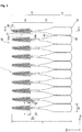
Fig. 1 is a schematic front view showing the structure of an interdental cleaning tool according to one embodiment of the present invention. -
Fig. 2 is a schematic side view showing the structure of the interdental cleaning tool according to one embodiment of the present invention. -
Fig. 3 is a cross-sectional view along line 3-3 ofFig. 1 . -
Fig. 4 is an end face view along line 4-4 ofFig. 1 . -
Fig. 5 is an end face view along line 5-5 ofFig. 1 . -
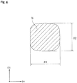
Fig. 6 is an end face view along line 6-6 ofFig. 1 . - A preferred embodiment of the present invention will be described with reference to the accompanying drawings. As shown in
Fig. 1 to Fig. 3 , the interdental cleaning tool 1 according to one embodiment of the present invention includes abase material portion 10, and asoft portion 20 covering at least part of thebase material portion 10. The interdental cleaning tool 1 is individually cut off and separated from a connectedmember 40 of, for example, 10 interdental cleaning tools 1 joined together in parallel along a lateral direction (first direction) D1 of the interdental cleaning tool 1 by a pair of connectingsections base material portion 10. - The
base material portion 10 includes abase section 11 for a user to hold, and ashaft section 12 extending from the distal end of thebase section 11 along a longitudinal direction D2 perpendicular to the lateral direction D1 of the interdental cleaning tool 1 to be inserted between the teeth of the user. Herein, the side toward theshaft section 12 as viewed from thebase section 11 is referred to as the distal side, and the side toward thebase section 11 as viewed from theshaft section 12 is referred to as the proximal side. - The
base section 11 is formed in a flat, wide plate-like shape, for example. In this embodiment, for example, it is formed in a flat cuboidal shape, but may be formed in other shapes as long as the user can hold it. - The
shaft section 12 extends from the distal end that is one end of thebase section 11 along the longitudinal direction D2. Theshaft section 12 includes atransition section 13 continuing from thebase section 11 and extending in a flat plate-like shape, and adistal end section 14 extending from the distal end of thetransition section 13 to the distal end of theshaft section 12 in a thin pin-like shape. Thetransition section 13 is formed in a tapered shape wherein the width defined along the lateral direction D1 is reduced toward the distal end of theshaft section 12. - The
base material portion 10 is molded from a synthetic resin material, for example. Synthetic resin materials that can be adopted include, for example, polypropylene, polyethylene, ABS (acrylonitrile butadiene styrene), polybutylene terephthalate, polycarbonate, polyethylene terephthalate, polystyrene, polyacetal, polyamide, and so on. The synthetic resin material may additionally contain a fiber material such as glass fiber in a ratio of about 1 to 30 weight%, for example. - The
soft portion 20 includes a coveringsection 21 that covers an outer circumferential surface of at least part of thedistal end section 14 of theshaft section 12, and a plurality ofprojections 22 projecting from thecovering section 21. Theprojections 22 are formed in a conical shape, for example, and arranged helically around the axis of thedistal end section 14 of theshaft section 12 from the proximal end to the distal end of thecovering section 21. The height of theprojections 22 from the outer circumferential surface of the coveringsection 21 decreases from the proximal end to the distal end of thecovering section 21. - The
soft portion 20 is made of a resin material having a lower hardness than that of the synthetic resin material of thebase section 10. Elastomer can be adopted as the resin material. Applicable elastomers include styrene-based elastomer, silicone, olefin-based elastomer, polyester-based elastomer, and so on. The elastomer should preferably have a shore A durometer hardness (JISK6253) of 10 to 50, more preferably 10 to 40. In this embodiment, the elastomer has a shore A durometer hardness of 35. - The
base material portion 10 of the interdental cleaning tool 1 of this embodiment is designed to have a length L1 defined along the longitudinal direction D2 of 45 mm to 55 mm, for example. Thebase section 11 is designed to have a width W1 defined along the lateral direction D1 of 3 mm to 10 mm, for example. Further, thebase section 11 is designed to have a thickness T1 defined along a thickness direction (second direction) D3 perpendicular to the lateral direction D1 and longitudinal direction D2 of 0.5 mm to 10 mm, for example. - The covering
section 21 is designed to have a length defined along the longitudinal direction D2 from its proximal end to the distal end of 10 mm to 25 mm, for example. Thecovering section 21 is formed with a uniform thickness at the same position in the longitudinal direction D2, the thickness being 0.1 mm to 2.5 mm, for example. Theprojections 22 are designed to have a height from the outer circumferential surface of thecovering section 21 of 0.1 mm to 5.0 mm, for example. The issue the present invention is meant to solve mentioned above is more prone to arise when the coveringsection 21 is longer, meaning, the longer the covering section, the more the effect of the invention is achieved. In this respect, the length of the coveringsection 21 defined along the longitudinal direction D2 should preferably be 15 mm or more, more preferably 16 mm or more, and particularly preferably 18 mm or more. - The
distal end section 14 includes adistal end region 14a extending from the distal end toward the proximal end thereof, and a proximal end region 14b extending from thedistal end region 14a to thetransition section 13. At least part of thedistal end region 14a is covered by the coveringsection 21. As shown inFig. 4 , thedistal end region 14a is designed to have a substantially true-circle cross section perpendicular to the axis of theshaft section 12. Thedistal end region 14a is formed in a tapered shape, radially reducing from the proximal end toward the distal end thereof, its diameter (i.e., first outer dimension X1 defined along the lateral direction D1, or second outer dimension X2 defined along the thickness direction D3) being 0.6 mm to 3.0 mm, for example. In this embodiment, thedistal end region 14a is designed to have a length from the distal end to the proximal end of thesoft portion 20 of 15 mm, and the proximal end region 14b is similarly designed to have a length of 5 mm. - On the other hand, as shown in
Fig. 5 andFig. 6 , the proximal end region 14b is designed to have a cross section whose first outer dimension X1 defined along the lateral direction D1 is larger than the second outer dimension X2 defined along the thickness direction D3 perpendicular to the lateral direction D1. The second outer dimension X2 of the proximal end region 14b should preferably be set to 1.0 mm or more, and more preferably 1.1 mm or more. The ratio between the first outer dimension X1 and the second outer dimension X2 (X2/X1) is set to 0.20 to 0.98, and may more preferably be 0.30 to 0.97. This ratio (X2/X1) may be set to increase gradually from a distal end section toward a base section of the proximal end region 14b. Note, X1 denotes the relatively longer one of the first outer dimension X1 and the second outer dimension X2, i.e., the outer dimension along the lateral direction D1 need not necessarily be X1. In this embodiment, the proximal end region is designed to have a cross-sectional shape that transforms to more rectangular from the distal end region 14b toward thetransition section 12. For example, while the cross section inFig. 5 near the distal end region 14b is substantially oval, it is more rectangular near thetransition section 12. - The interdental cleaning tool 1 described above allows its
shaft section 12 to flex more easily in the thickness direction D3 along the second outer dimension X2, while not allowing theshaft section 12 to flex as easily in the lateral direction D1 along the first outer dimension X1, because of the second outer dimension X2 being smaller than the first outer dimension X1 in the proximal end region 14b of theshaft section 12. In other words, theshaft section 12 has increased strength in the lateral direction D1 as compared to the longitudinal direction D2. Therefore, easy insertion between the teeth can be realized through use of the interdental cleaning tool 1 in a way that lets the tool flex in the thickness direction D3 in which it can flex more easily. - On the other hand, the cleaning effect can be increased through use of the interdental cleaning tool 1 in which it is firmly pressed against the teeth in the lateral direction D1 in which it flexes less easily, because this allows the covering
section 21 andprojections 22 to be pressed against the side faces of the teeth more firmly. Therefore, easy insertion between teeth and improved cleaning effect can both be achieved. - Since the
distal end region 14a located further toward the distal side of theshaft section 12 than the proximal end region 14b is designed to have a substantially true-circle cross section, so that thedistal end region 14a can bend in any direction perpendicular to the axis of theshaft section 12. Therefore, in addition to the flexibility in the thickness direction D3 of the proximal end region 14b described above, the degree of bendability of theshaft section 12 when the interdental cleaning tool 1 is inserted between the teeth can further be increased. - Next, a production method of the interdental cleaning tool 1 is described below. First, the filling space of a primary mold conforming to the outer shape of the
base material portion 10 is filled with a molten synthetic resin material to mold thebase material portion 10. After that, thebase material portion 10 is taken out of the primary mold. Then, the moldedbase material portion 10 is arranged inside the filling space of a secondary mold conforming to the outer shape of thesoft portion 20. The filling space is filled with a molten elastomer to mold thesoft portion 20. Thus the interdental cleaning tool 1 is mold. After that, the interdental cleaning tool 1 is taken out of the secondary mold. - The covering
section 21 andprojections 22 of the interdental cleaning tool 1 described above may cover not only thedistal end region 14a but also the proximal end region 14b of theshaft section 12. The settings of the first outer dimension X1 and second outer dimension X2 may be applied not only to the proximal end region 14b but also to part or all of thedistal end region 14a. The first outer dimension X1 may be set along the thickness direction D3, and the second outer dimension X2 smaller than the first outer dimension X1 may be set along the lateral direction D1. - The embodiment described above is given for facilitating the understanding of the present invention and not for limiting the interpretation of the present invention. Various elements in the embodiment, arrangements, materials, conditions, shapes, sizes and so on are not limited to the shown examples and may be changed as required. Also, various features shown in different forms of embodiment can be partially interchanged or combined.
-
- 1
- Interdental cleaning tool
- 10
- Base material portion
- 11
- Base section
- 12
- Shaft section
- 20
- Soft portion
- D1
- Lateral direction (first direction)
- D3
- Thickness direction (second direction)
- X1
- First outer dimension
- X2
- Second outer dimension
Claims (6)
- An interdental cleaning tool comprising:a base material portion including a base section and a shaft section extending from the base section; anda soft portion covering at least a part of the shaft section, whereinthe at least the part of the shaft section has a first outer dimension defined in a first direction and a second outer dimension, defined in a second direction perpendicular to the first direction and smaller than the first outer dimension, in a cross section of the shaft section perpendicular to an axial direction of the shaft section.
- The interdental cleaning tool according to claim 1, wherein the first outer dimension is defined in a direction parallel to a plane extending along the base section.
- The interdental cleaning tool according to claim 1 or 2, wherein the first outer dimension and the second outer dimension have a ratio (second outer dimension/first outer dimension) of 0.20 to 0.98.
- The interdental cleaning tool according to any one of claims 1 to 3, wherein the second outer dimension is 1.0 mm or more.
- The interdental cleaning tool according to any one of claims 1 to 4, wherein the soft portion has a length, which is defined in an axial direction of the shaft section, of 15 mm or more.
- The interdental cleaning tool according to any one of claims 1 to 5, wherein the first outer dimension and the second outer dimension have a ratio (second outer dimension/first outer dimension) gradually increasing from a distal end section toward the base section of the shaft section.
Applications Claiming Priority (2)
| Application Number | Priority Date | Filing Date | Title |
|---|---|---|---|
| JP2018248341A JP7652528B2 (en) | 2018-12-28 | 2018-12-28 | Interdental Cleaning Tools |
| PCT/JP2019/045066 WO2020137251A1 (en) | 2018-12-28 | 2019-11-18 | Interdental cleaning tool |
Publications (2)
| Publication Number | Publication Date |
|---|---|
| EP3900670A1 true EP3900670A1 (en) | 2021-10-27 |
| EP3900670A4 EP3900670A4 (en) | 2022-08-24 |
Family
ID=71129713
Family Applications (1)
| Application Number | Title | Priority Date | Filing Date |
|---|---|---|---|
| EP19904019.7A Withdrawn EP3900670A4 (en) | 2018-12-28 | 2019-11-18 | Interdental cleaning tool |
Country Status (4)
| Country | Link |
|---|---|
| US (2) | US20220047365A1 (en) |
| EP (1) | EP3900670A4 (en) |
| JP (1) | JP7652528B2 (en) |
| WO (1) | WO2020137251A1 (en) |
Families Citing this family (4)
| Publication number | Priority date | Publication date | Assignee | Title |
|---|---|---|---|---|
| JP7652528B2 (en) | 2018-12-28 | 2025-03-27 | 小林製薬株式会社 | Interdental Cleaning Tools |
| JP2020103851A (en) | 2018-12-28 | 2020-07-09 | 小林製薬株式会社 | Interdental cleaning tool |
| JP7417353B2 (en) | 2018-12-28 | 2024-01-18 | 小林製薬株式会社 | Manufacturing method for interdental cleaning tools |
| CN115804496A (en) | 2021-09-14 | 2023-03-17 | 株式会社Lg生活健康 | Interdental brush and method for manufacturing the same |
Family Cites Families (53)
| Publication number | Priority date | Publication date | Assignee | Title |
|---|---|---|---|---|
| US4280518A (en) | 1979-04-09 | 1981-07-28 | Gambaro Susan M | Tooth cleaning implement |
| US5775346A (en) * | 1996-02-14 | 1998-07-07 | Advanced Implant Technologies Inc. | Interproximal dental appliances |
| DE19642431A1 (en) * | 1996-10-15 | 1998-04-16 | Coronet Werke Gmbh | Interdental cleaner and process for its manufacture |
| JP3002668B1 (en) * | 1998-07-14 | 2000-01-24 | 株式会社広栄社 | Brush toothpick |
| DE202006019175U1 (en) | 2006-12-19 | 2007-07-12 | Tschuljukin, Nikolai | Cleaning brush for toe interim |
| US8376470B2 (en) | 2008-01-07 | 2013-02-19 | Ponzini S.P.A. | Method for manufacturing a toothbrush and a bristle head thereof, toothbrush obtained by said method and mould for such method |
| US20090230756A1 (en) * | 2008-03-12 | 2009-09-17 | Ranir, Llc | Interdental cleaning tool |
| DE102008029499A1 (en) | 2008-06-20 | 2009-12-24 | M + C Schiffer Gmbh | Brush, in particular toothbrush and method for its manufacture |
| US20100015567A1 (en) * | 2008-07-18 | 2010-01-21 | Jean-Jacques Elbaz | Dental Hygiene Tool |
| WO2010014623A1 (en) * | 2008-07-29 | 2010-02-04 | Sunstar Americas, Inc. | Interdental cleaners and methods for making same |
| EP2345342B1 (en) | 2010-01-18 | 2013-04-24 | Albéa Services | Cosmetic applicator assembly |
| JP5929346B2 (en) | 2012-03-13 | 2016-06-01 | サンスター株式会社 | Interdental cleaning tool manufacturing method |
| JP6060505B2 (en) | 2012-03-22 | 2017-01-18 | サンスター株式会社 | Interdental cleaning tool |
| ES2945858T3 (en) | 2012-05-24 | 2023-07-10 | Sunstar Suisse Sa | interdental cleaning tool |
| EP4098147B1 (en) * | 2012-07-02 | 2024-12-18 | Trisa Holding AG | Interdental brush |
| DE102012015664A1 (en) | 2012-08-09 | 2014-02-13 | Interbros Gmbh | Interdental cleaners |
| DE102012015663A1 (en) * | 2012-08-09 | 2014-05-15 | Interbros Gmbh | Interdental cleaners |
| WO2014054011A1 (en) * | 2012-10-02 | 2014-04-10 | Allan Coopersmith | Dental device |
| WO2014070542A1 (en) | 2012-11-05 | 2014-05-08 | The Gillette Company | Toothbrush comprising elastomeric cleaning elements over-molded with a harder plastic and method for producing the same |
| ITTO20130060U1 (en) * | 2013-04-11 | 2014-10-12 | Spada Forniture Di Spada Giuseppe | DENTAL CLEANING DEVICE. |
| US9603685B2 (en) | 2013-09-09 | 2017-03-28 | LeedTech Resources Company, LLC | Method of manufacturing an interdental cleaner |
| WO2015118078A1 (en) * | 2014-02-06 | 2015-08-13 | Pheneo Gmbh | Dental instrument for applying dental compounds |
| HUE032148T2 (en) * | 2014-03-06 | 2017-09-28 | Tepe Munhygienprodukter Ab | Interdental cleaner |
| US20150257861A1 (en) * | 2014-03-17 | 2015-09-17 | Ranir, Llc | Interproximal cleaning tool and method of manufacture |
| DE102014011405A1 (en) | 2014-08-06 | 2016-02-11 | Interbros Gmbh | Interdental cleaner and process for its preparation |
| WO2016076373A1 (en) | 2014-11-11 | 2016-05-19 | サンスター スイス エスエー | Production method for interdental cleaning tool |
| JP6575054B2 (en) * | 2014-11-11 | 2019-09-18 | サンスター株式会社 | Interdental cleaning tool and manufacturing method thereof |
| US20170319309A1 (en) * | 2014-11-11 | 2017-11-09 | Sunstar Inc. | Interdental cleaning device |
| JP5977382B2 (en) * | 2015-01-16 | 2016-08-24 | 小林製薬株式会社 | Interdental cleaning tool |
| WO2016167191A1 (en) | 2015-04-16 | 2016-10-20 | ライオン株式会社 | Interdental brush |
| WO2016199834A1 (en) * | 2015-06-08 | 2016-12-15 | サンスター スイス エスエー | Interdental cleaning tool |
| JP6750328B2 (en) | 2015-06-12 | 2020-09-02 | サンスター株式会社 | Interdental cleaning tool |
| JP6915234B2 (en) | 2015-06-12 | 2021-08-04 | サンスター株式会社 | Intertooth cleaning tool |
| JP2017119095A (en) * | 2015-12-26 | 2017-07-06 | サンスター株式会社 | Interdental cleaner and manufacturing process thereof |
| JP6455422B2 (en) | 2015-12-28 | 2019-01-23 | サンスター株式会社 | Interdental cleaning tool |
| JP6675212B2 (en) | 2016-02-03 | 2020-04-01 | ライオン株式会社 | Manufacturing method of interdental cleaning tool |
| JP6281586B2 (en) | 2016-03-07 | 2018-02-21 | サンスター株式会社 | Interdental cleaning tool |
| JP6292246B2 (en) | 2016-03-07 | 2018-03-14 | サンスター株式会社 | Interdental cleaning tool |
| DE102016005012A1 (en) | 2016-04-26 | 2017-10-26 | Interbros Gmbh | Interdental cleaner |
| DE202016102620U1 (en) | 2016-05-17 | 2017-08-18 | Geka Gmbh | Cosmetic applicator with special bristle |
| DE102016007658A1 (en) * | 2016-06-23 | 2017-12-28 | Interbros Gmbh | Interdental cleaners |
| JP6387386B2 (en) | 2016-12-28 | 2018-09-05 | 小林製薬株式会社 | Interdental cleaning tool manufacturing method |
| JP6752139B2 (en) | 2016-12-28 | 2020-09-09 | 小林製薬株式会社 | How to make an interdental cleaning tool |
| JP7066323B2 (en) * | 2017-02-28 | 2022-05-13 | 小林製薬株式会社 | Intertooth cleaning tool |
| JP6961372B2 (en) | 2017-03-23 | 2021-11-05 | 小林製薬株式会社 | Manufacturing method of interdental cleaning tool |
| US11672326B2 (en) * | 2017-09-19 | 2023-06-13 | Trisa Holding Ag | Applicator device |
| EP3461367B1 (en) | 2017-09-28 | 2020-04-22 | The Procter & Gamble Company | Method of making a unitary brush head and unitary toothbrush head |
| DE102017010561A1 (en) * | 2017-11-15 | 2019-05-16 | Interbros Gmbh | Interdental cleaner |
| JP2020103851A (en) | 2018-12-28 | 2020-07-09 | 小林製薬株式会社 | Interdental cleaning tool |
| JP7417353B2 (en) | 2018-12-28 | 2024-01-18 | 小林製薬株式会社 | Manufacturing method for interdental cleaning tools |
| JP7652528B2 (en) | 2018-12-28 | 2025-03-27 | 小林製薬株式会社 | Interdental Cleaning Tools |
| US20200405462A1 (en) * | 2019-06-25 | 2020-12-31 | Solo-Med GmbH | Method for cleaning an implant in an interdental space and interdental cleaning brush |
| DE102021113332A1 (en) | 2021-05-21 | 2022-11-24 | Interbros Gmbh | interdental cleaner |
-
2018
- 2018-12-28 JP JP2018248341A patent/JP7652528B2/en active Active
-
2019
- 2019-11-18 WO PCT/JP2019/045066 patent/WO2020137251A1/en not_active Ceased
- 2019-11-18 EP EP19904019.7A patent/EP3900670A4/en not_active Withdrawn
- 2019-11-18 US US17/418,373 patent/US20220047365A1/en not_active Abandoned
-
2023
- 2023-09-08 US US18/463,481 patent/US12491055B2/en active Active
Also Published As
| Publication number | Publication date |
|---|---|
| US20220047365A1 (en) | 2022-02-17 |
| US12491055B2 (en) | 2025-12-09 |
| JP2020103850A (en) | 2020-07-09 |
| JP7652528B2 (en) | 2025-03-27 |
| WO2020137251A1 (en) | 2020-07-02 |
| US20230414334A1 (en) | 2023-12-28 |
| EP3900670A4 (en) | 2022-08-24 |
Similar Documents
| Publication | Publication Date | Title |
|---|---|---|
| US12491055B2 (en) | Interdental cleaning tool | |
| JP6547829B2 (en) | Interdental cleaning tool | |
| EP3219291B1 (en) | Interdental cleaning device | |
| US20180193119A1 (en) | Interdental cleaner | |
| US12383385B2 (en) | Interdental cleaning tool | |
| JPWO2016167191A1 (en) | Interdental brush | |
| EP3900669A1 (en) | Method for manufacturing interdental cleaning tool | |
| EP3603569A1 (en) | Method of manufacturing inter-dental cleaning tool | |
| EP3785663B1 (en) | Interdental cleaning tool | |
| EP3903635B1 (en) | Interdental cleaning tool | |
| JP2004242781A (en) | Interdental toothbrush | |
| EP3646814A1 (en) | Interdental cleaning tool | |
| JP2018140088A (en) | Interdental cleaning tool | |
| JP2017000570A (en) | Interdental cleaner | |
| JP7565672B2 (en) | Interdental Cleaning Tools | |
| JP7565673B2 (en) | Interdental Cleaning Tools | |
| JP7575886B2 (en) | Interdental Cleaning Tools | |
| JP7100094B2 (en) | Intertooth cleaning tool | |
| JP2025129272A (en) | Interdental cleaning tools | |
| CN111685571B (en) | Manual garlic peeling accessory | |
| JP7765885B2 (en) | Interdental cleaning tools | |
| EP3646813A1 (en) | Interdental cleaning tool | |
| WO2022004578A1 (en) | Interdental cleaning tool | |
| JP2026071193A (en) | Interdental cleaning tools | |
| WO2022004577A1 (en) | Interdental cleaning tool |
Legal Events
| Date | Code | Title | Description |
|---|---|---|---|
| STAA | Information on the status of an ep patent application or granted ep patent |
Free format text: STATUS: THE INTERNATIONAL PUBLICATION HAS BEEN MADE |
|
| PUAI | Public reference made under article 153(3) epc to a published international application that has entered the european phase |
Free format text: ORIGINAL CODE: 0009012 |
|
| STAA | Information on the status of an ep patent application or granted ep patent |
Free format text: STATUS: REQUEST FOR EXAMINATION WAS MADE |
|
| 17P | Request for examination filed |
Effective date: 20210719 |
|
| AK | Designated contracting states |
Kind code of ref document: A1 Designated state(s): AL AT BE BG CH CY CZ DE DK EE ES FI FR GB GR HR HU IE IS IT LI LT LU LV MC MK MT NL NO PL PT RO RS SE SI SK SM TR |
|
| DAV | Request for validation of the european patent (deleted) | ||
| DAX | Request for extension of the european patent (deleted) | ||
| A4 | Supplementary search report drawn up and despatched |
Effective date: 20220726 |
|
| RIC1 | Information provided on ipc code assigned before grant |
Ipc: A61C 15/02 20060101AFI20220720BHEP |
|
| STAA | Information on the status of an ep patent application or granted ep patent |
Free format text: STATUS: THE APPLICATION IS DEEMED TO BE WITHDRAWN |
|
| 18D | Application deemed to be withdrawn |
Effective date: 20230223 |