EP3900555A1 - Electronic device, information processing device, and program - Google Patents
Electronic device, information processing device, and program Download PDFInfo
- Publication number
- EP3900555A1 EP3900555A1 EP19919204.8A EP19919204A EP3900555A1 EP 3900555 A1 EP3900555 A1 EP 3900555A1 EP 19919204 A EP19919204 A EP 19919204A EP 3900555 A1 EP3900555 A1 EP 3900555A1
- Authority
- EP
- European Patent Office
- Prior art keywords
- function
- information
- electronic device
- inhalation
- unit
- Prior art date
- Legal status (The legal status is an assumption and is not a legal conclusion. Google has not performed a legal analysis and makes no representation as to the accuracy of the status listed.)
- Pending
Links
- 230000010365 information processing Effects 0.000 title claims abstract description 50
- 239000000443 aerosol Substances 0.000 claims abstract description 125
- 230000005540 biological transmission Effects 0.000 claims abstract description 35
- 238000000034 method Methods 0.000 claims description 56
- 239000000463 material Substances 0.000 claims description 22
- 230000006870 function Effects 0.000 description 179
- 238000004891 communication Methods 0.000 description 57
- 241000208125 Nicotiana Species 0.000 description 35
- 235000002637 Nicotiana tabacum Nutrition 0.000 description 35
- 239000000796 flavoring agent Substances 0.000 description 25
- 235000019634 flavors Nutrition 0.000 description 25
- 238000000889 atomisation Methods 0.000 description 21
- 238000010586 diagram Methods 0.000 description 20
- 238000010438 heat treatment Methods 0.000 description 17
- 239000007788 liquid Substances 0.000 description 16
- 238000005401 electroluminescence Methods 0.000 description 6
- 239000011148 porous material Substances 0.000 description 5
- 239000012530 fluid Substances 0.000 description 4
- 239000004973 liquid crystal related substance Substances 0.000 description 4
- 239000000203 mixture Substances 0.000 description 4
- 239000002994 raw material Substances 0.000 description 4
- PEDCQBHIVMGVHV-UHFFFAOYSA-N Glycerine Chemical compound OCC(O)CO PEDCQBHIVMGVHV-UHFFFAOYSA-N 0.000 description 3
- DNIAPMSPPWPWGF-UHFFFAOYSA-N Propylene glycol Chemical compound CC(O)CO DNIAPMSPPWPWGF-UHFFFAOYSA-N 0.000 description 3
- 238000005485 electric heating Methods 0.000 description 3
- 239000003571 electronic cigarette Substances 0.000 description 3
- 239000002657 fibrous material Substances 0.000 description 3
- 230000004044 response Effects 0.000 description 3
- 239000007787 solid Substances 0.000 description 3
- 239000000872 buffer Substances 0.000 description 2
- 238000001514 detection method Methods 0.000 description 2
- 230000000694 effects Effects 0.000 description 2
- 238000013507 mapping Methods 0.000 description 2
- 210000000214 mouth Anatomy 0.000 description 2
- 239000006199 nebulizer Substances 0.000 description 2
- 230000002093 peripheral effect Effects 0.000 description 2
- 239000004065 semiconductor Substances 0.000 description 2
- NOOLISFMXDJSKH-UTLUCORTSA-N (+)-Neomenthol Chemical compound CC(C)[C@@H]1CC[C@@H](C)C[C@@H]1O NOOLISFMXDJSKH-UTLUCORTSA-N 0.000 description 1
- OKTJSMMVPCPJKN-UHFFFAOYSA-N Carbon Chemical compound [C] OKTJSMMVPCPJKN-UHFFFAOYSA-N 0.000 description 1
- 229920000742 Cotton Polymers 0.000 description 1
- NOOLISFMXDJSKH-UHFFFAOYSA-N DL-menthol Natural products CC(C)C1CCC(C)CC1O NOOLISFMXDJSKH-UHFFFAOYSA-N 0.000 description 1
- 241000196324 Embryophyta Species 0.000 description 1
- 235000006679 Mentha X verticillata Nutrition 0.000 description 1
- 235000002899 Mentha suaveolens Nutrition 0.000 description 1
- 235000001636 Mentha x rotundifolia Nutrition 0.000 description 1
- 229910052799 carbon Inorganic materials 0.000 description 1
- 230000001413 cellular effect Effects 0.000 description 1
- 235000019504 cigarettes Nutrition 0.000 description 1
- 238000004590 computer program Methods 0.000 description 1
- 239000003814 drug Substances 0.000 description 1
- 229940079593 drug Drugs 0.000 description 1
- 239000000835 fiber Substances 0.000 description 1
- 239000003365 glass fiber Substances 0.000 description 1
- 230000010354 integration Effects 0.000 description 1
- 229940041616 menthol Drugs 0.000 description 1
- 238000010295 mobile communication Methods 0.000 description 1
- 230000036651 mood Effects 0.000 description 1
- 230000003287 optical effect Effects 0.000 description 1
- 239000000843 powder Substances 0.000 description 1
- 230000000391 smoking effect Effects 0.000 description 1
- 150000005846 sugar alcohols Polymers 0.000 description 1
- 235000019505 tobacco product Nutrition 0.000 description 1
- 238000002604 ultrasonography Methods 0.000 description 1
- 238000009834 vaporization Methods 0.000 description 1
- 230000008016 vaporization Effects 0.000 description 1
- XLYOFNOQVPJJNP-UHFFFAOYSA-N water Substances O XLYOFNOQVPJJNP-UHFFFAOYSA-N 0.000 description 1
Images







Classifications
-
- A—HUMAN NECESSITIES
- A24—TOBACCO; CIGARS; CIGARETTES; SIMULATED SMOKING DEVICES; SMOKERS' REQUISITES
- A24F—SMOKERS' REQUISITES; MATCH BOXES; SIMULATED SMOKING DEVICES
- A24F40/00—Electrically operated smoking devices; Component parts thereof; Manufacture thereof; Maintenance or testing thereof; Charging means specially adapted therefor
- A24F40/65—Devices with integrated communication means, e.g. wireless communication means
-
- A—HUMAN NECESSITIES
- A24—TOBACCO; CIGARS; CIGARETTES; SIMULATED SMOKING DEVICES; SMOKERS' REQUISITES
- A24F—SMOKERS' REQUISITES; MATCH BOXES; SIMULATED SMOKING DEVICES
- A24F40/00—Electrically operated smoking devices; Component parts thereof; Manufacture thereof; Maintenance or testing thereof; Charging means specially adapted therefor
- A24F40/50—Control or monitoring
-
- A—HUMAN NECESSITIES
- A24—TOBACCO; CIGARS; CIGARETTES; SIMULATED SMOKING DEVICES; SMOKERS' REQUISITES
- A24F—SMOKERS' REQUISITES; MATCH BOXES; SIMULATED SMOKING DEVICES
- A24F40/00—Electrically operated smoking devices; Component parts thereof; Manufacture thereof; Maintenance or testing thereof; Charging means specially adapted therefor
- A24F40/60—Devices with integrated user interfaces
Definitions
- the present invention relates to an electronic device, an information processing device, and a program.
- PTL 1 discloses a system for recording, in a user terminal or a server, an inhalation history or the like of an inhalation device and making full use of the recorded information for a use plan of the inhalation device or control of its frequency of use.
- an object of the present invention is to provide an electronic device, an information processing device, and a program which enable easy management of the functions.
- An electronic device generates an aerosol for inhalation.
- the electronic device includes a control unit that controls generation of the aerosol using an aerosol generation unit, a storage unit that stores a function ID for identifying a function of the electronic device, and a transmission unit that transmits the function ID to a different information processing device.
- This aspect enables electronic devices to be managed, not on a device-by-device basis, but on a function-by-function basis. Therefore, even when a new model of electronic device is introduced, the new model may be easily managed only by changing a combination of functions.
- the present invention provides an electronic device, an information processing device, and a program which enable easy management of the functions.
- Fig. 1 is a diagram illustrating an exemplary configuration of an information processing system 1 according to an embodiment of the present invention.
- the information processing system 1 includes a server 10, user terminals 20, and electronic devices 30 associated with the user terminals 20.
- the electronic devices 30 may be devices which generate aerosols for inhalation, and are also called, for example, "flavor inhalation articles". Examples of the electronic devices 30 may include an electronic cigarette, a heated tobacco product, a conventional cigarette, and a medical nebulizer.
- a dotted line with which a user terminal 20 and an electronic device 30 are enclosed, indicates that the user terminal 20 and the electronic device 30, which are enclosed with the dotted line, are associated with each other.
- the server 10 is capable of mutual data transmission/reception with each of the user terminals 20 over a communication network N by using TCP/IP or the like as a communication protocol.
- the server 10 may be capable of mutual data transmission/reception with the electronic devices 30 over the communication network N by using TCP/IP or the like as a communication protocol.
- the communication network N is constructed, for example, by using the Internet, a leased communication line (for example, a community antenna television (CATV) line), a mobile communication network (including base stations and the like), and a gateway.
- CATV community antenna television
- the server 10 provides, to the user terminals 20 and the electronic devices 30 over the communication network N, a given service for managing functions of the electronic devices 30.
- the user terminals 20 are terminal devices of users who use the given service provided by the server 10. For example, personal computers, portable information terminals, such as personal digital assistants (PDAs) and smartphones, cellular telephones, and game machines are used as the user terminals 20.
- the user terminals 20 store an application program (app) for using the given service provided by the server 10.
- the electronic devices 30 are associated with the user terminals 20, for example, by registering the device IDs of the electronic devices 30 in the user terminals 20.
- the electronic devices 30 are connected to the user terminals 20 so as to be capable of mutual information transmission/reception through near field communication or the like. Multiple electronic devices 30 may be connected to a single user terminal 20.
- Fig. 2 is a schematic diagram illustrating an exemplary functional configuration of the server 10 according to the embodiment of the present invention.
- the server 10 includes, for example, a communication unit 11, a storage unit 12, and a processing unit 13.
- the communication unit 11 includes a communication interface circuit for connecting the server 10 to the communication network N.
- the communication unit 11 transmits data, which is supplied from the processing unit 13, to information processing devices, such as the user terminals 20 and the electronic devices 30, over the communication network N.
- the communication unit 11 also supplies the processing unit 13 with data received from information processing devices, such as the user terminals 20 and the electronic devices 30, over the communication network N.
- the storage unit 12 includes, for example, at least one of the following devices: a semiconductor memory, a magnetic disk device, and an optical disk device.
- the storage unit 12 stores, for example, driver programs, operating system programs, application programs, and data which are used in processes performed by the processing unit 13.
- the computer programs may be installed in the storage unit 12 by using known setup programs or the like, for example, from computer-readable portable recording media, such as a CD-ROM and a DVD-ROM.
- the storage unit 12 also stores, as data, a function management table illustrated in Fig. 3 , a management information table illustrated in Fig. 4 , an inhalation-area management table illustrated in Fig. 5 , and the like.
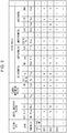
- Fig. 3 is a schematic diagram illustrating an example of the function management table.
- the function management table is, for example, a table which is used to manage functions of the electronic devices 30 and which is generated for each user ID.
- Examples of the functions of the electronic devices 30 may include, but are not limited to, an output function, an aerosol generation function, and a position information function.
- Examples of the output function may include a display function, a lighting function, a vibration function, and a voice function.
- the function management table describes the "function type” of each function of the electronic devices 30 in the first row, the “detail” of each function in the second row, and the "function ID” for identifying each function in the third row.
- “Function type” indicates the types of the functions of the electronic device 30. Specifically, examples of “function type” include “aerosol generation function”, “position information function”, and “output function”. Further, examples of “output function” include “display function”, “lighting function”, “vibration function", and "voice function”.
- “Aerosol generation function” indicates information about the attributes of the electronic devices 30 which are obtained when the aerosol generation methods of the electronic devices 30 are classified with a given classification criterion.
- the classification criterion may include, but are not particularly limited to, the inhaled-material component, the phase state of the inhaled material which is not being used, the method of generating an aerosol containing the inhaled material, and the heating method.
- the classification criterion is based on "the inhaled-material component”
- the aerosol generation function is classified, for example, on the basis of whether tobacco or flavor is contained.
- the aerosol generation function is classified, for example, on the basis of whether the inhaled material is a solid, a liquid, a gas, in an intermediate state of these, or in a combination of these.
- the classification criterion is based on "the method of generating an aerosol containing the inhaled material”
- the aerosol generation function is classified, for example, on the basis of whether the method is burning, heating, or vaporization.
- the aerosol generation function is classified, for example, on the basis of whether the method is electric heating, heating with a carbon heat source, or IH heating. In the example in Fig.
- T-type indicates the type of including tobacco as an inhaled-material component and directly heating tobacco at a high temperature by using a heater or the like.
- E-type indicates the following type: tobacco is not used; a liquid is contained as an inhaled-material component; an aerosol generated through electric heating of the liquid in a device or a dedicated cartridge is inhaled.
- I-type indicates the following type: for example, tobacco is contained as an inhaled-material component; the tobacco is not directly heated; a liquid is heated and atomized for tobacco passing through.
- “Aerosol generation function” may be defined by using a classification criterion generated by appropriately combining multiple classification criteria including the classification criteria described above and other classification criteria.
- Position information function indicates methods of obtaining position information of the electronic devices 30.
- position information function include “GPS”.
- Display function indicates the type of a display for displaying images and the like. Examples of “display function” include “liquid-crystal” indicating a liquid-crystal display and “EL” indicating electroluminescence (EL).
- Lighting function indicates the type of a lighting unit which emits light by using a light-emitting member. Examples of “lighting function” include “LED” indicating light emitting diode (LED).
- Volibration function indicates the type of a vibration unit which generates vibrations. Examples of “vibration function” include “eccentric type” indicating an eccentric motor.
- Voice function indicates the type of a voice output unit for outputting voices.
- Examples of “voice function” include “D-type” indicating a dynamic speaker and “C-type” indicating a condenser speaker.
- Delivery which is "none”, indicates that no functions of "function type” are included.
- a system administrator may set, in advance, the classifications of "function type”, “detail”, and "function ID”. If a new function which does not belong to any of the classifications is introduced, the system administrator may create a new classification corresponding to the function.
- function IDs received from the electronic devices 30, the user terminals 20, and the like are registered.
- function IDs associated with each device ID may be registered.
- “Y” indicates that the electronic device 30 has the function associated with the function ID
- "N” indicates that the electronic device 30 does not have the function associated with the device ID.
- function IDs associated with a user ID, not with device IDs may be registered collectively. In this case, “Y” indicates that the user has any electronic device 30 having the function associated with the function ID; "N” indicates that the user does not have any electronic device 30 having the function associated with the function ID.
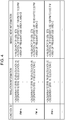
- Fig. 4 is a schematic diagram illustrating an example of the management information table.
- the management information table is a table for managing inhalation information and management information for each type of the aerosol generation function.
- the inhalation information includes any information about a user's inhalation of aerosols using their electronic devices 30.
- the inhalation information may include the numbers of inhalations, inhalation locations, inhalation strengths, the types of aerosol source, inhalation times, the types of devices used, and inhalation profiles.
- the management information is information obtained by processing the inhalation information by using any method, and is information for grasping and managing the user's inhalation habit.
- the management information table may be a collection of inhalation information collected from multiple users without discrimination of the users.
- the management information table illustrated in Fig. 4 includes inhalation information collected from multiple users, and also includes management information generated from the inhalation information.
- the management information table may be a collection of each user's inhalation information collected from the user with discrimination of users.
- the management information table illustrated in Fig. 4 includes inhalation information for a specific user and management information generated from the inhalation information.
- the management information table includes, for example, "function ID”, “inhalation information”, and "management information”.
- “Function ID” is information indicating a function ID of the aerosol generation function.
- “Inhalation information” is inhalation information associated with the function ID of the aerosol generation function. The association is not particularly limiting, and, for example, the inhalation information may include dates and times when inhalation was performed by using the aerosol generation function corresponding to the function ID, and information about their inhalation areas. Examples of an inhalation area may include an area in which users' inhalation is permitted by a law, a regulation, a municipal law, or the like, and map information associated with the area.
- Management information may be information obtained by processing inhalation information by using any method.
- “management information” may be information indicating the result of a statistical process on information, such as dates and times and inhalation areas, included in the inhalation information.
- the management information table includes, for each function ID, "frequency of use”, “duration of frequent use”, and “inhalation area of frequent use” which are generated on the basis of "inhalation information”.
- Frequency of use is information indicating the frequency of use of the aerosol generation function corresponding to the device ID.
- frequency of use is information indicating the ratio of a time of use of the aerosol generation function corresponding to the function ID with respect to the total time for "inhalation information" included in the management information table.
- “Duration of frequent use” is information indicating a duration of frequent use of the aerosol generation function corresponding to the function ID.
- “duration of frequent use” may be a duration in which the frequency of inhalations in a certain duration (the ratio of the number of inhalations or the inhalation time period in a given period) is equal to or greater than a given threshold.
- the frequency which is divided into stages (for example, five stages), of inhalations in each duration may be displayed as "management information”.
- “Inhalation area of frequent use” is information indicating an inhalation area in which the aerosol generation function corresponding to the function ID is frequently used.
- “inhalation area of frequent use” may be an inhalation area in which the frequency of inhalations (the ratio of the number of inhalations or the inhalation time period in the inhalation area in a given period) is equal to or greater than a given threshold.
- the frequency, which is divided into stages (for example, five stages), of inhalations in each inhalation area may be displayed as "management information”.
- management information Through collective management of inhalation information for each function ID of the aerosol generation function, information about which aerosol generation function was used by a user with how much inhalation may be grasped. Further, by generating management information based on inhalation information for each function ID of the aerosol generation function, information about which aerosol generation function was used by a user with how much inhalation may be grasped in detail.
- Fig. 5 is a schematic diagram illustrating an example of the inhalation-area management table.
- the inhalation-area management table is a table for managing the types of usable aerosol generation functions for each inhalation area.
- the inhalation-area management table includes, as items, for example, "inhalation area ID", "location”, and the function IDs of "aerosol generation function".
- “Inhalation area ID” indicates IDs for identifying inhalation areas.
- “Location” indicates information indicating the positions of the inhalation areas, and may be the location names, the addresses, and position information.
- Y included in the cells in the "function ID” column indicates, for example, that use of the type of aerosol generation function corresponding to the function ID is permitted in the inhalation area corresponding to the inhalation area ID.
- N included in the cells in the "function ID” column indicates that use of the type of aerosol generation function corresponding to the function ID is prohibited or is not permitted in the inhalation area corresponding to the inhalation area ID.
- the following cells are “N”: the cell for the aerosol generation function whose function ID is "FM-t” (that is, “T-type” in which tobacco is included); the cell for the aerosol generation function whose function ID is "FM-i” (that is, “I-type” in which tobacco passes through by heating and atomizing a liquid), whereas the cell for the aerosol generation function whose function ID is "FM-e” (that is, “E-type” in which tobacco is not included) is “Y”.
- E-type in which tobacco is not included
- T-type in which tobacco is included
- I-type in which tobacco passes through by heating and atomizing a liquid.
- the processing unit 13 has one or more processors and their peripheral circuitry.
- the processing unit 13 has overall control of the entire operation of the server 10, and is, for example, a central processing unit (CPU).
- the processing unit 13 controls operations of the communication unit 11 and the like so that various processes of the server 10 are performed in an appropriate procedure according to programs and the like stored in the storage unit 12.
- the processing unit 13 performs the processes on the basis of programs (such as driver programs, operating system programs, and application programs) stored in the storage unit 12.
- the processing unit 13 is capable of executing multiple programs (such as application programs) in parallel.
- the processing unit 13 includes a registration unit 131, a management-information generation unit 132, a control-information generation unit 133, a transmission unit 134, and a receiving unit 135.
- the registration unit 131 stores various types of information about the electronic devices 30 and the like in the storage unit 12. For example, the registration unit 131 registers, in the function management table described by using Fig. 3 , function IDs and device IDs which are received from the electronic devices 30 and/or the user terminals 20.
- the management-information generation unit 132 generates the management information on the basis of the function IDs and the inhalation information.
- the management-information generation unit 132 may generate management information on the basis of inhalation information collected from multiple users without discrimination of the users, or may generate the management information for a specific user on the basis of the inhalation information of the user.
- the control-information generation unit 133 generates control information for controlling the electronic devices 30, for example, on the basis of position information of the electronic devices 30, the user terminals 20, or the like, information indicating the aerosol generation function, and the inhalation area information.
- the transmission unit 134 transmits various types of information through the communication unit 11, for example, to other information processing devices.
- the transmission unit 134 transmits, to the user terminals 20, the electronic devices 30, and the like, user IDs, device IDs, function IDs, position information, inhalation information, management information, control information, given request signals, and the like.
- the receiving unit 135 receives various types of information through the communication unit 11, for example, from other information processing devices.
- the receiving unit 135 receives, from the user terminals 20, the electronic devices 30, and the like, user IDs, device IDs, function IDs, position information, inhalation information, management information, control information, given request signals, and the like.
- Fig. 6 is a schematic diagram illustrating an exemplary functional configuration of the user terminal 20 according to the embodiment of the present invention.
- the user terminal 20 includes, for example, a communication unit 21, a storage unit 22, an output unit 23, an operation unit 24, and a processing unit 25.
- the communication unit 21 includes a communication interface circuit, and connects the user terminal 20 to the communication network N.
- the communication unit 21 transmits data, which is supplied from the processing unit 25, over the communication network N to the server 10, the electronic device 30, and the like.
- the communication unit 21 also supplies the processing unit 25 with data received from the server 10, the electronic device 30, and the like over the communication network N.
- the storage unit 22 includes, for example, a semiconductor memory device.
- the storage unit 22 stores operating system programs, driver programs, application programs, data, and the like which are used in processes performed by the processing unit 25.
- the various programs may be installed in the storage unit 22 by using known setup programs and the like from computer-readable portable recording media, such as a CD-ROM and a DVD-ROM.
- the storage unit 22 may store, as data, a user ID, the device ID and/or the function IDs of the electronic device 30 associated with the user terminal 20, for example.
- the output unit 23 is implemented by using any of all types of devices which are capable of outputting a processing result from a process performed by the processing unit 25, or a combination of the devices.
- the output device is implemented by using any of all the types of devices which are capable of displaying display data according to the display data written in frame buffers, or a combination of the devices.
- Examples of the output device include, but are not limited to, a touch panel, a touch display, a monitor (such as a liquid-crystal display or an organic electroluminescence display (OELD) which is not limiting and is taken as an example), a head mounted display (HDM), projection mapping, a hologram, a device which is capable of displaying an image, text information, and the like, for example, in the air (which may be a vacuum), a speaker (voice output), and a printer. These types of output device may be capable of displaying display data in 3D.
- the output unit 23 may be a vibration element, such as an eccentric motor or a linear resonant actuator which is capable of generating vibrations.
- the operation unit 24 may be any device as long as the device may be used to operate the user terminal 20, and is, for example, a touch panel or key buttons. A user may input characters, numerals, symbols, and the like by using the operation unit 24. In response to a user's operation using the operation unit 24, the operation unit 24 generates a signal corresponding to the operation. The generated signal is supplied to the processing unit 25 as a user instruction.
- the processing unit 25 includes one or more processors and their peripheral circuitry.
- the processing unit 25 has overall control of the entire operation of the user terminal 20, and is, for example, a CPU.
- the processing unit 25 controls operations of the communication unit 21, the output unit 23, and the like so that various processes of the user terminal 20 are performed in an appropriate procedure, for example, on the basis of programs stored in the storage unit 22 or operations on the operation unit 24.
- the processing unit 25 performs processes on the basis of programs (such as operating system programs, driver programs, and application programs) stored in the storage unit 22.
- the processing unit 25 is capable of executing multiple programs (such as application programs) in parallel.
- the processing unit 25 includes, for example, a registration unit 251, a position-information acquiring unit 252, a pairing unit 253, a transmission unit 254, and a receiving unit 255.
- the registration unit 251 performs a process of registering, in the storage unit 22, various types of information about the electronic device 30.
- the registration unit 251 registers the function IDs and the device ID of the electronic device 30.
- the position-information acquiring unit 252 communicates with an artificial satellite through the communication unit 21, and thus obtains position information of the user terminal 20.
- the pairing unit 253 performs wireless communication, as a pairing process, with a different information processing device such as a user terminal 20 on the basis of any wireless communication standard, such as Bluetooth®, wireless local area network (LAN), Wi-Fi®, low power wide area (LPWA), or near field communication (NFC).
- a wireless communication standard such as Bluetooth®, wireless local area network (LAN), Wi-Fi®, low power wide area (LPWA), or near field communication (NFC).
- the pairing unit 253 receives/transmits a given key from/to a target information processing device, and then stores the given key in the storage unit 22. After that, through reception/transmission of packets including the key, near field communication may be implemented.
- the transmission unit 254 transmits various types of information through the communication unit 21, for example, to a different information processing device.
- the transmission unit 254 transmits, to the server 10, the electronic device 30, and the like, the user ID, the device ID, the function IDs, position information, inhalation information, management information, control information, given request signals, and the like.
- the receiving unit 255 receives various types of information through the communication unit 21, for example, from a different information processing device.
- the receiving unit 255 receives, from the server 10, the electronic device 30, and the like, the user ID, the device ID, the function IDs, position information, inhalation information, management information, control information, given request signals, and the like.
- An electronic device 30 may be of a type, as a first type, of heating tobacco directly at a high temperature.
- the electronic device 30 may be configured to generate an aerosol containing a flavor by heating an aerosol-source material such as a smoking article having a flavor-source material such as a filling containing an aerosol source and a flavor source.
- An electronic device 30 may be of a type, as a second type, of, without use of tobacco, including a liquid as an inhaled-material component, and causing inhalation of an aerosol generated through electric heating of the liquid in a device or a dedicated cartridge.
- An electronic device 30 may be of a type, as a third type, of including tobacco as an inhaled-material component, and making tobacco pass through by heating and atomizing a liquid without direct heating of the tobacco.
- Fig. 7 is a diagram illustrating an exemplary configuration of an electronic device 30 according to an embodiment of the present invention.
- the example in Fig. 7 corresponds to the third type described above.
- the electronic device 30 includes a first member 31 and a second member 32.
- the first member 31 may include an output unit 311, a battery 312, a sensor 313, a storage unit 314, a communication unit 315, an operation unit 316, and a processing unit 317.
- the second member 32 may include a reservoir 321, an atomization unit 322, an air intake channel 323, an aerosol channel 324, and a mouthpiece unit 325.
- Some of the components included in the first member 31 may be included in the second member 32.
- Some of the components included in the second member 32 may be included in the first member 31.
- the second member 32 may be configured so as be removable/attachable from/to the first member 31. Alternatively, all the components included in the first member 31 and the second member 32 may be included in the same case instead of the first member 31 and the second member 32.
- the electronic device 30 includes a third member 33.
- the second member 32 and the third member 33 form an aerosol generation unit which generates an aerosol.
- the third member 33 may include a flavor source 331.
- the flavor source 331 may contain a fragrance-inhaling-taste component contained in tobacco.
- the third member 33 may be configured so as to be removable/attachable from/to the second member 32. Alternatively, all the components included in the second member 32 and the third member 33 may be included in the same case instead of the second member 32 and the third member 33.
- the reservoir 321 holds an aerosol source.
- the reservoir 321 is formed of a fibrous or porous material, and holds an aerosol source as a liquid in spaces between fibers or in pores in the porous material.
- the fibrous or porous material described above for example, cotton, glass fiber, or tobacco raw material may be used.
- the reservoir 321 may be formed as a tank containing liquid.
- the aerosol source is a liquid, such as a polyalcohol, for example, glycerol or propylene glycol, or water.
- the electronic device 30 is a medical inhalator such as a nebulizer
- the aerosol source may also contain a drug for a patient's inhalation.
- the aerosol source may contain a tobacco raw material and an extract originated from tobacco raw material, which emit a fragrance-inhaling-taste component through heating. In this case, without the third member 33 being attached, an aerosol containing a flavor component is generated.
- the reservoir 321 may have a structure in which the aerosol source is replenished by the amount of consumption. Alternatively, the reservoir 321 may be formed so that the reservoir 321 itself is replaced when the aerosol source is consumed.
- the aerosol source is not limited to a liquid, and may be a solid.
- the reservoir 321 whose aerosol source is solid may be a hollow container, for example, without use of a fibrous or porous material.
- the atomization unit 322 is formed so as to generate an aerosol through atomization of the aerosol source.
- the sensor 313 detects an inhalation, the atomization unit 322 generates an aerosol.
- a wick (not illustrated) may be disposed so as to couple the reservoir 321 to the atomization unit 322.
- a part of the wick goes into the reservoir 321, and is in contact with the aerosol source.
- the other part of the wick extends to the atomization unit 322.
- the aerosol source is conveyed from the reservoir 321 to the atomization unit 322 by using the capillary effect of the wick.
- the atomization unit 322 includes a heater electrically connected to the battery 312.
- the heater is disposed so as to be in contact with or close to the wick.
- a control unit 317a controls the heater of the atomization unit 322 so that the aerosol source is atomized by heating the aerosol source conveyed through the wick.
- Another example of the atomization unit 322 may be an ultrasonic atomizer which atomizes the aerosol source through ultrasound vibration.
- the air intake channel 323 is connected to the atomization unit 322, and the air intake channel 323 connects with the outside of the electronic device 30.
- An aerosol generated by the atomization unit 322 is mixed with air taken in through the air intake channel 323.
- the fluid mixture of the aerosol and air is conveyed into the aerosol channel 324.
- the aerosol channel 324 has a tubular structure for conveying the fluid mixture of the aerosol, which is generated by the atomization unit 322, and air to the mouthpiece unit 325.
- the flavor source 331 is a component for adding a flavor to an aerosol.
- the flavor source 331 is disposed at a position along the aerosol channel 324.
- the fluid mixture of an aerosol which is generated by the atomization unit 322, and air (note that the fluid mixture may be hereinafter called an aerosol simply), flows through the aerosol channel 324 to the mouthpiece unit 325.
- the flavor source 331 is disposed downstream of the atomization unit 322 along the aerosol flow.
- the flavor source 331 is positioned, along the aerosol channel 324, closer to the mouthpiece unit 325 than the atomization unit 322 is. Therefore, an aerosol generated by the atomization unit 322 passes through the flavor source 331 before reaching the mouthpiece unit 325.
- the flavor source 331 may be originated from tobacco, such as shredded tobacco or processed products obtained by changing the shape of tobacco raw material into grains, sheets, or powder.
- the flavor source 331 may be originated from a non-tobacco material made from a plant (for example, mint or an herb) other than tobacco.
- the flavor source 331 may contain a flavor component such as menthol.
- the reservoir 321 may also have a material containing a fragrance-inhaling-taste component.
- the electronic device 30 may be configured so that the flavor source 331 holds a flavor material originated from tobacco and the reservoir 321 contains a flavor material originated from a non-tobacco material.
- the mouthpiece unit 325 is disposed at the end of the aerosol channel 324, and is configured so that the aerosol channel 324 is opened to the outside of the electronic device 30. As illustrated, the aerosol channel 324 extends across the second member 32 and the third member 33. The mouthpiece unit 325 is provided for the third member 33.
- a user holds the mouthpiece unit 325 in their mouth for inhalation.
- the user takes air, containing an aerosol with a flavor added thereto, into their oral cavity.
- the output unit 311 is implemented by using any of all the types of devices which are capable of outputting a processing result from a process performed by the processing unit 317, or a combination of these, and, for example, has a display function, a lighting function, a vibration function, and a voice function.
- the output device is implemented by using any of all the types of devices which are capable of displaying display data according to the display data written in frame buffers, or a combination of these.
- Examples of the output device include, but are not limited to, a touch panel, a touch display, a monitor (such as a liquid-crystal display or an organic electroluminescence (EL) display which is not limiting and is taken as an example), a head mounted display (HDM), projection mapping, a hologram, a device which is capable of displaying an image, text information, and the like in the air (may be a vacuum), a speaker (voice output), and a printer. These output devices may be capable of displaying display data in 3D.
- the output unit 33 may be a vibration element, such as an eccentric motor or a linear resonant actuator, which is capable of generating vibrations.
- the battery 312 is a power supply which accumulates power and which supplies power to the components of the electronic device 30, such as the output unit 311, the sensor 313, the storage unit 314, and the atomization unit 322.
- the battery 312 may be recharged through connection to an external power supply via a given port (not illustrated) of the electronic device 30.
- the battery 312 may be removed, as a single unit, from the first member 31 or the electronic device 30, or may be replaced with a new battery 312.
- the battery 312 may be replaced with a new battery 312 by replacing the entire first member 31 with a new first member 31.
- the sensor 313 may include a pressure sensor, which detects a change of pressure in the air intake channel 323 and/or the aerosol channel 324, or a flow rate sensor which detects a flow rate.
- the sensor 313 may include a weight sensor which detects the weight of a component such as the reservoir 321.
- the sensor 313 may be configured so as to count puffs of a user who uses the electronic device 30.
- the sensor 313 may be configured so as to integrate the time of power energization to the atomization unit 322.
- the sensor 313 may be configured so as to detect the height of the liquid level in the reservoir 321.
- the sensor 313 may be configured so as to detect detachment/attachment of the second member 32 from/to the first member 31, or detachment/attachment of the third member 33 from/to the second member 32.
- the sensor 313 may be configured so as to detect the state of charge (SOC), the integrated value of current, the voltage, and the like of the battery 312.
- SOC state of charge
- the integrated value of current may be obtained, for example, by using a current integration method or an SOC-OCV (Open Circuit Voltage) method.
- the sensor 313 may be an operation button or the like operable by a user.
- the storage unit 314 is storage media, such as a ROM, a RAM, and a flash memory.
- the storage unit 314 may store, in addition to the computer-executable commands described above, setting data and the like necessary for control of the electronic device 30.
- the storage unit 314 may store various data, such as the method of controlling the output unit 311 (the form or the like, such as lighting, voice, or vibration), values detected by the sensor 313, the heating history of the atomization unit 322.
- the storage unit 314 may store, for example, the user ID, the device ID for identifying the electronic device 30, and the function IDs for identifying the functions of the electronic device 30.
- the communication unit 315 includes a communication interface circuit, and connects the electronic device 30 to the communication network N or a near field communication network.
- the communication unit 315 transmits data, which is supplied from the processing unit 317, to the server 10, the user terminal 20, or the like over the communication network N or the near field communication network.
- the communication unit 315 supplies the processing unit 317 with data received from the server 10 or the user terminal 20 over the communication network N or the near field communication network.
- the operation unit 316 may be any device as long as the device may be used to operate the electronic device 30.
- the operation unit 316 is a touch panel or key buttons.
- a user may input characters, numerals, symbols, and the like by using the operation unit 316.
- the operation unit 316 In response to a user's operation using the operation unit 316, the operation unit 316 generates a signal corresponding to the operation. The generated signal is supplied to the processing unit 317 as a user instruction.
- the processing unit 317 may be an electronic circuit module formed as a microprocessor or a microcomputer.
- the processing unit 317 may be configured so as to control operations of the electronic device 30 according to the computer-executable commands stored in the storage unit 314.
- the processing unit 317 reads data from the storage unit 314 for control of the electronic device 30 when necessary, and stores data in the storage unit 314 when necessary.
- the processing unit 317 may include the control unit 317a, an inhalation-information generation unit 317b, a position-information acquiring unit 317c, a pairing unit 317d, a transmission unit 317e, and a receiving unit 317f.
- the control unit 317a controls generation of an aerosol using the aerosol generation unit (the second member 32 and the third member 33).
- the control unit 317a exerts the control by using a method corresponding to the aerosol generation method for the electronic device 30.
- the inhalation-information generation unit 317b generates inhalation information.
- the inhalation information may include, for example, the number of inhalations, an inhalation location, an inhalation strength, the type of the aerosol source, an inhalation time, the type of the device used, and an inhalation profile.
- the inhalation-information generation unit 317b generates the inhalation information (for example, the number of inhalations, an inhalation location, an inhalation strength, an inhalation time, and an inhalation profile), for example, on the basis of position information supplied from the position-information acquiring unit 317c, a detection signal (described below) in accordance with the type of the aerosol source, detection signals about inhalation supplied from the sensor 313.
- the position-information acquiring unit 317c obtains position information of the electronic device 30, for example, through communication with an artificial satellite via the communication unit 315.
- the pairing unit 317d performs wireless communication, as a pairing process, for example, with a different information processing device such as the user terminal 20 on the basis of any wireless communication standard, such as Bluetooth®, wireless local area network (LAN), Wi-Fi®, low power wide area (LPWA), or near field communication (NFC).
- a wireless communication standard such as Bluetooth®, wireless local area network (LAN), Wi-Fi®, low power wide area (LPWA), or near field communication (NFC).
- the pairing unit 317d receives/transmits a given key from/to a target information processing device, and then stores the given key in the storage unit 314. After that, through reception/transmission of packets including the key, near field communication may be implemented.
- the transmission unit 317e transmits various types of information, for example, to a different information processing device through the communication unit 315.
- the transmission unit 317e transmits, to the server 10, the user terminal 20, and the like, the user ID, the device ID, the function IDs, position information, inhalation information, management information, control information, given request signals, and the like.
- the receiving unit 317f receives various types of information, for example, from a different information processing device through the communication unit 315.
- the receiving unit 317f receives, from the server 10, the user terminal 20, and the like, the user ID, the device ID, the function IDs, position information, inhalation information, management information, control information, given request signals, and the like.
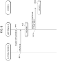
- Fig. 8 is a diagram illustrating an exemplary operation sequence of a function registration process of the information processing system 1 according to the embodiment of the present invention. The process is such that, prior to use of an electronic device 30, the function IDs of the electronic device 30 are registered in a user terminal 20 and the server 10.
- the transmission unit 254 of the user terminal 20 transmits a signal for requesting the device ID, to the electronic device 30, for example, in accordance with a user's operation using the operation unit 24 (S10). At that time, the transmission unit 254 of the user terminal 20 may also request the device ID from the electronic device 30.
- the transmission unit 317e of the electronic device 30 transmits, to the user terminal 20, the function IDs of the electronic device 30, which are stored in the storage unit 314 of the electronic device 30, as a response to the signal for requesting function IDs (S11).
- the transmission unit 317e of the electronic device 30 may further transmit the device ID of the electronic device 30 to the user terminal 20.
- the registration unit 251 of the user terminal 20 stores, in the storage unit 22, the function IDs received from the electronic device 30, and thus registers the function IDs (S12). At that time, when the device ID of the electronic device 30 is also received, the registration unit 251 of the user terminal 20 stores the device ID in association with the function IDs in the storage unit 22, and thus also registers the function IDs.
- the transmission unit 254 of the user terminal 20 transmits, to the server 10, the user ID, the function IDs received from the electronic device 30, and a signal for requesting registration of the function IDs (S13). At that time, the transmission unit 254 of the user terminal 20 may also transmit the device ID of the electronic device 30 to the server 10.
- the registration unit 131 of the server 10 Upon reception, from the user terminal 20, of the function IDs of the electronic device 30 and the signal for requesting registration of the function IDs, the registration unit 131 of the server 10 registers the received function IDs, for example, in the function management table described by using Fig. 3 (S14). At that time, the registration unit 131 of the server 10 may also register the device ID in the function management table. Then, the pre-registration process ends.
- Fig. 9 is a diagram illustrating an exemplary operation sequence of a management-information generation process of the information processing system 1 according to the embodiment of the present invention.
- the process is such that, after inhalation information, which is generated when a user performs inhalations by using an electronic device 30, is transmitted to the server 10 through the user terminal 20, the server 10 generates management information on the basis of the inhalation information.
- the electronic device 30 performs an inhalation process in accordance with a user's operation using the operation unit 34 of the electronic device 30 (S20). Specifically, the control unit 317a of the electronic device 30 controls generation of an aerosol using the aerosol generation unit (the second member 32 and the third member 33).
- the inhalation-information generation unit 317b of the electronic device 30 generates the inhalation information (S21). At that time, the inhalation-information generation unit 317b may detect any parameters, for example, about the strength of the user's inhalation using the electronic device 30, and the number of inhalations.
- the position information of the electronic device 30, which is obtained by the position-information acquiring unit 317c, may be included in the inhalation information.
- the inhalation-information generation unit 317b generates, as the inhalation information, for example, the number of inhalations, the inhalation location, the inhalation strength, the type of aerosol forming material, the inhalation time, the type of the device used, the inhalation profile, and the like.
- the transmission unit 317e of the electronic device 30 transmits the generated inhalation information to the user terminal 20 (S22).
- the registration unit 251 of the user terminal 20 stores the received inhalation information in the storage unit 22, and thus registers the inhalation information (S23).
- the registration unit 251 may include, in the inhalation information, the position information of the user terminal 20 which is obtained by the position-information acquiring unit 252 of the user terminal 20.
- the transmission unit 254 of the user terminal 20 transmits, to the server 10, the inhalation information and a signal for requesting registration of the inhalation information (S24).
- the registration unit 131 of the server 10 registers the inhalation information, which is received from the user terminal 20, in the management information table stored in the storage unit 12 (S25).
- the management-information generation unit 132 of the server 10 generates management information on the basis of the function IDs, which are recorded in the function management table, and the inhalation information (S26). At that time, the management-information generation unit 132 may generate management information on the basis of the inhalation information collected from multiple users without discrimination of the users, or may generate management information for a specific user on the basis of the inhalation information of the user.
- "management information" may be information obtained by processing inhalation information by using any method. For example, "management information” may be information indicating a statistical processing result from information, such as the dates and times and the inhalation areas included in the inhalation information. Then, the management-information generation process ends.
- Fig. 10 is a diagram illustrating an exemplary operation sequence of a control process of the information processing system 1 according to the embodiment of the present invention. The process is such that the server 10 generates control information and an electronic device 30 performs various operations in accordance with the control information.
- the pairing unit 317d of the electronic device 30 and the pairing unit 253 of the user terminal 20 performs a pairing process (S30). Specifically, the pairing unit 317d of the electronic device 30 and the pairing unit 253 of the user terminal 20 receives/transmits a given key.
- the pairing unit 317d of the electronic device 30 stores the given key in the storage unit 32 of the electronic device 30.
- the pairing unit 253 of the user terminal 20 stores the given key in the storage unit 32.
- the transmission unit 254 of the user terminal 20 transmits, to the server 10, a request signal for requesting control information (S32).
- the request signal may include any information about the electronic device 30.
- the request signal may include the device ID of the electronic device 30 or the function IDs of the electronic device 30.
- the function IDs of the electronic device 30 may include function IDs of the aerosol generation function.
- the request signal may include position information obtained by the electronic device 30 and/or position information obtained by the user terminal 20.
- the control-information generation unit 133 of the server 10 Upon reception, from the user terminal 20, of the request signal for requesting control information, the control-information generation unit 133 of the server 10 generates control information in accordance with information included in the request signal (S33). For example, when the request signal includes the device ID, the control-information generation unit 133 may refer to the function management table and may extract the function IDs associated with the device ID. Then, the control-information generation unit 133 may generate control information for controlling the functions corresponding to the function IDs. For example, when the request signal includes function IDs, the control-information generation unit 133 may refer to the function management table, and may generate control information for controlling the functions corresponding to the function IDs.
- the control-information generation unit 133 may determine an inhalation area on the basis of the position information, and may refer to the inhalation-area management table, which is stored in the storage unit 12, to generate control information for controlling the function (for example, the aerosol generation function) usable in the determined inhalation area.
- the form of the control using the control information is not particularly limiting as long as the form relates to control of the function.
- the form may be one for controlling switching ON/OFF the function, adjustment of parameters such as the strength and the like of the function, and switching the mode of the function.
- the transmission unit 134 of the server 10 transmits the generated control information to the user terminal 20 (S34).
- the output unit 23 of the user terminal 20 performs an output process for outputting the content about the control information in accordance with the control information received from the server 10 (S35).
- the form and the content of the output are not particularly limiting.
- the output unit 23 of the user terminal 20 may display, on the display, information indicating the aerosol generation function usable in the area, and information indicating that the user is in an area in which inhalation is permitted, or may output the information by voice by using a speaker.
- the transmission unit 254 of the user terminal 20 transmits, to the electronic device 30, the control information received from the server 10 (S36).
- the output unit 311 of the electronic device 30 performs an output process for outputting the content about the control information in accordance with the control information received from the user terminal 20 (S37).
- the form and the content of the output are not particularly limiting.
- the electronic device 30 may display, on the display, information indicating the aerosol generation function usable in the area, and information indicating that the user is in an area in which inhalation is permitted, or may output the information by voice by using a speaker.
- the electronic device 30 may perform display with lighting, for example, through an LED according to a pattern predetermined in accordance with notification content.
- the transmission unit 134 of the server 10 may transmit the generated control information directly to the electronic device 30.
- the control unit 317a of the electronic device 30 Upon reception of the control information, the control unit 317a of the electronic device 30 performs an operation in accordance with the control information (S38). For example, the control unit 317a controls generation of an aerosol using the aerosol generation unit (the second member 32 and the third member 33) in accordance with the control information. Then, the control process ends.
Landscapes
- Engineering & Computer Science (AREA)
- Human Computer Interaction (AREA)
- Computer Networks & Wireless Communication (AREA)
- Medicinal Preparation (AREA)
- User Interface Of Digital Computer (AREA)
Abstract
Description
- The present invention relates to an electronic device, an information processing device, and a program.
- Heretofore, techniques related to inhalation devices which generate aerosols for inhalation have been developed. For example,
PTL 1 discloses a system for recording, in a user terminal or a server, an inhalation history or the like of an inhalation device and making full use of the recorded information for a use plan of the inhalation device or control of its frequency of use. - PTL 1: International Publication No.
2018/025217 - However, a wide variety of functions have recently been developed along with the widespread use of inhalation devices. This state leads to a wider variety of user preferences. More users use multiple inhalation devices selectively depending on their moods and situations. In view of this point, a method of the related art, in which a wide variety of functions of inhalation devices are managed in association with the device IDs which are used to identify the inhalation devices and which serve as central information, has the following disadvantage: every time a new inhalation device is released, all the functions of the inhalation device need to be managed in association with the device ID of the inhalation device, causing a heavy management burden.
- Accordingly, an object of the present invention is to provide an electronic device, an information processing device, and a program which enable easy management of the functions.
- An electronic device according to an aspect of the present invention generates an aerosol for inhalation. The electronic device includes a control unit that controls generation of the aerosol using an aerosol generation unit, a storage unit that stores a function ID for identifying a function of the electronic device, and a transmission unit that transmits the function ID to a different information processing device.
- This aspect enables electronic devices to be managed, not on a device-by-device basis, but on a function-by-function basis. Therefore, even when a new model of electronic device is introduced, the new model may be easily managed only by changing a combination of functions.
- The present invention provides an electronic device, an information processing device, and a program which enable easy management of the functions.
-
- [
Fig. 1] Fig. 1 is a diagram illustrating an exemplary configuration of aninformation processing system 1 according to an embodiment of the present invention. - [
Fig. 2] Fig. 2 is a schematic diagram illustrating an exemplary functional configuration of aserver 10 according to an embodiment of the present invention. - [
Fig. 3] Fig. 3 is a schematic diagram illustrating an exemplary function management table. - [
Fig. 4] Fig. 4 is a schematic diagram illustrating an exemplary management information table. - [
Fig. 5] Fig. 5 is a schematic diagram illustrating an exemplary inhalation-area management table. - [
Fig. 6] Fig. 6 is a schematic diagram illustrating an exemplary functional configuration of auser terminal 20 according to an embodiment of the present invention. - [
Fig. 7] Fig. 7 is a schematic diagram illustrating an exemplary functional configuration of anelectronic device 30 according to an embodiment of the present invention. - [
Fig. 8] Fig. 8 is a diagram illustrating an exemplary operation sequence of a function registration process of theinformation processing system 1 according to an embodiment of the present invention. - [
Fig. 9] Fig. 9 is a diagram illustrating an exemplary operation sequence of a management-information generation process of theinformation processing system 1 according to an embodiment of the present invention. - [
Fig. 10] Fig. 10 is a diagram illustrating an exemplary operation sequence of a control process of theinformation processing system 1 according to an embodiment of the present invention. - Referring to the attached drawings, a preferable embodiment of the present invention will be described. (Components designated with identical reference numerals in the figures have the identical or similar configurations.)
-
Fig. 1 is a diagram illustrating an exemplary configuration of aninformation processing system 1 according to an embodiment of the present invention. As illustrated inFig. 1 , theinformation processing system 1 includes aserver 10,user terminals 20, andelectronic devices 30 associated with theuser terminals 20. Theelectronic devices 30 may be devices which generate aerosols for inhalation, and are also called, for example, "flavor inhalation articles". Examples of theelectronic devices 30 may include an electronic cigarette, a heated tobacco product, a conventional cigarette, and a medical nebulizer. InFig. 1 , a dotted line, with which auser terminal 20 and anelectronic device 30 are enclosed, indicates that theuser terminal 20 and theelectronic device 30, which are enclosed with the dotted line, are associated with each other. Theserver 10 is capable of mutual data transmission/reception with each of theuser terminals 20 over a communication network N by using TCP/IP or the like as a communication protocol. In addition, theserver 10 may be capable of mutual data transmission/reception with theelectronic devices 30 over the communication network N by using TCP/IP or the like as a communication protocol. The communication network N is constructed, for example, by using the Internet, a leased communication line (for example, a community antenna television (CATV) line), a mobile communication network (including base stations and the like), and a gateway. - The
server 10 provides, to theuser terminals 20 and theelectronic devices 30 over the communication network N, a given service for managing functions of theelectronic devices 30. Theuser terminals 20 are terminal devices of users who use the given service provided by theserver 10. For example, personal computers, portable information terminals, such as personal digital assistants (PDAs) and smartphones, cellular telephones, and game machines are used as theuser terminals 20. Theuser terminals 20 store an application program (app) for using the given service provided by theserver 10. Theelectronic devices 30 are associated with theuser terminals 20, for example, by registering the device IDs of theelectronic devices 30 in theuser terminals 20. Theelectronic devices 30 are connected to theuser terminals 20 so as to be capable of mutual information transmission/reception through near field communication or the like. Multipleelectronic devices 30 may be connected to asingle user terminal 20. -
Fig. 2 is a schematic diagram illustrating an exemplary functional configuration of theserver 10 according to the embodiment of the present invention. As illustrated inFig. 2 , theserver 10 includes, for example, acommunication unit 11, astorage unit 12, and aprocessing unit 13. - The
communication unit 11 includes a communication interface circuit for connecting theserver 10 to the communication network N. Thecommunication unit 11 transmits data, which is supplied from theprocessing unit 13, to information processing devices, such as theuser terminals 20 and theelectronic devices 30, over the communication network N. Thecommunication unit 11 also supplies theprocessing unit 13 with data received from information processing devices, such as theuser terminals 20 and theelectronic devices 30, over the communication network N. - The
storage unit 12 includes, for example, at least one of the following devices: a semiconductor memory, a magnetic disk device, and an optical disk device. Thestorage unit 12 stores, for example, driver programs, operating system programs, application programs, and data which are used in processes performed by theprocessing unit 13. The computer programs may be installed in thestorage unit 12 by using known setup programs or the like, for example, from computer-readable portable recording media, such as a CD-ROM and a DVD-ROM. Thestorage unit 12 also stores, as data, a function management table illustrated inFig. 3 , a management information table illustrated inFig. 4 , an inhalation-area management table illustrated inFig. 5 , and the like. -
Fig. 3 is a schematic diagram illustrating an example of the function management table. The function management table is, for example, a table which is used to manage functions of theelectronic devices 30 and which is generated for each user ID. Examples of the functions of theelectronic devices 30 may include, but are not limited to, an output function, an aerosol generation function, and a position information function. Examples of the output function may include a display function, a lighting function, a vibration function, and a voice function. - As illustrated in
Fig. 3 , the function management table describes the "function type" of each function of theelectronic devices 30 in the first row, the "detail" of each function in the second row, and the "function ID" for identifying each function in the third row. "Function type" indicates the types of the functions of theelectronic device 30. Specifically, examples of "function type" include "aerosol generation function", "position information function", and "output function". Further, examples of "output function" include "display function", "lighting function", "vibration function", and "voice function". - "Aerosol generation function" indicates information about the attributes of the
electronic devices 30 which are obtained when the aerosol generation methods of theelectronic devices 30 are classified with a given classification criterion. Examples of the classification criterion may include, but are not particularly limited to, the inhaled-material component, the phase state of the inhaled material which is not being used, the method of generating an aerosol containing the inhaled material, and the heating method. When the classification criterion is based on "the inhaled-material component", the aerosol generation function is classified, for example, on the basis of whether tobacco or flavor is contained. When the classification criterion is based on "the phase state of the inhaled material which is not being used", the aerosol generation function is classified, for example, on the basis of whether the inhaled material is a solid, a liquid, a gas, in an intermediate state of these, or in a combination of these. When the classification criterion is based on "the method of generating an aerosol containing the inhaled material", the aerosol generation function is classified, for example, on the basis of whether the method is burning, heating, or vaporization. When the classification criterion is based on "the heating method", the aerosol generation function is classified, for example, on the basis of whether the method is electric heating, heating with a carbon heat source, or IH heating. In the example inFig. 3 , "T-type" indicates the type of including tobacco as an inhaled-material component and directly heating tobacco at a high temperature by using a heater or the like. "E-type" indicates the following type: tobacco is not used; a liquid is contained as an inhaled-material component; an aerosol generated through electric heating of the liquid in a device or a dedicated cartridge is inhaled. "I-type" indicates the following type: for example, tobacco is contained as an inhaled-material component; the tobacco is not directly heated; a liquid is heated and atomized for tobacco passing through. "Aerosol generation function" may be defined by using a classification criterion generated by appropriately combining multiple classification criteria including the classification criteria described above and other classification criteria. "Position information function" indicates methods of obtaining position information of theelectronic devices 30. Examples of "position information function" include "GPS". "Display function" indicates the type of a display for displaying images and the like. Examples of "display function" include "liquid-crystal" indicating a liquid-crystal display and "EL" indicating electroluminescence (EL). "Lighting function" indicates the type of a lighting unit which emits light by using a light-emitting member. Examples of "lighting function" include "LED" indicating light emitting diode (LED). "Vibration function" indicates the type of a vibration unit which generates vibrations. Examples of "vibration function" include "eccentric type" indicating an eccentric motor. "Voice function" indicates the type of a voice output unit for outputting voices. Examples of "voice function" include "D-type" indicating a dynamic speaker and "C-type" indicating a condenser speaker. "Detail", which is "none", indicates that no functions of "function type" are included. - For example, a system administrator may set, in advance, the classifications of "function type", "detail", and "function ID". If a new function which does not belong to any of the classifications is introduced, the system administrator may create a new classification corresponding to the function.
- In the function management table, function IDs received from the
electronic devices 30, theuser terminals 20, and the like are registered. For example, as illustrated inFig. 3 , function IDs associated with each device ID may be registered. In this case, "Y" indicates that theelectronic device 30 has the function associated with the function ID; "N" indicates that theelectronic device 30 does not have the function associated with the device ID. UnlikeFig. 3 , function IDs associated with a user ID, not with device IDs, may be registered collectively. In this case, "Y" indicates that the user has anyelectronic device 30 having the function associated with the function ID; "N" indicates that the user does not have anyelectronic device 30 having the function associated with the function ID. -
Fig. 4 is a schematic diagram illustrating an example of the management information table. The management information table is a table for managing inhalation information and management information for each type of the aerosol generation function. The inhalation information includes any information about a user's inhalation of aerosols using theirelectronic devices 30. For example, the inhalation information may include the numbers of inhalations, inhalation locations, inhalation strengths, the types of aerosol source, inhalation times, the types of devices used, and inhalation profiles. The management information is information obtained by processing the inhalation information by using any method, and is information for grasping and managing the user's inhalation habit. - The management information table may be a collection of inhalation information collected from multiple users without discrimination of the users. In this case, the management information table illustrated in
Fig. 4 includes inhalation information collected from multiple users, and also includes management information generated from the inhalation information. Alternatively, the management information table may be a collection of each user's inhalation information collected from the user with discrimination of users. In this case, the management information table illustrated inFig. 4 includes inhalation information for a specific user and management information generated from the inhalation information. - As illustrated in
Fig. 4 , the management information table includes, for example, "function ID", "inhalation information", and "management information". "Function ID" is information indicating a function ID of the aerosol generation function. "Inhalation information" is inhalation information associated with the function ID of the aerosol generation function. The association is not particularly limiting, and, for example, the inhalation information may include dates and times when inhalation was performed by using the aerosol generation function corresponding to the function ID, and information about their inhalation areas. Examples of an inhalation area may include an area in which users' inhalation is permitted by a law, a regulation, a municipal law, or the like, and map information associated with the area. "Management information" may be information obtained by processing inhalation information by using any method. For example, "management information" may be information indicating the result of a statistical process on information, such as dates and times and inhalation areas, included in the inhalation information. For example, in the example inFig. 4 , the management information table includes, for each function ID, "frequency of use", "duration of frequent use", and "inhalation area of frequent use" which are generated on the basis of "inhalation information". "Frequency of use" is information indicating the frequency of use of the aerosol generation function corresponding to the device ID. More specifically, "frequency of use" is information indicating the ratio of a time of use of the aerosol generation function corresponding to the function ID with respect to the total time for "inhalation information" included in the management information table. "Duration of frequent use" is information indicating a duration of frequent use of the aerosol generation function corresponding to the function ID. Specifically, "duration of frequent use" may be a duration in which the frequency of inhalations in a certain duration (the ratio of the number of inhalations or the inhalation time period in a given period) is equal to or greater than a given threshold. The frequency, which is divided into stages (for example, five stages), of inhalations in each duration may be displayed as "management information". "Inhalation area of frequent use" is information indicating an inhalation area in which the aerosol generation function corresponding to the function ID is frequently used. Specifically, "inhalation area of frequent use" may be an inhalation area in which the frequency of inhalations (the ratio of the number of inhalations or the inhalation time period in the inhalation area in a given period) is equal to or greater than a given threshold. The frequency, which is divided into stages (for example, five stages), of inhalations in each inhalation area may be displayed as "management information". Thus, through collective management of inhalation information for each function ID of the aerosol generation function, information about which aerosol generation function was used by a user with how much inhalation may be grasped. Further, by generating management information based on inhalation information for each function ID of the aerosol generation function, information about which aerosol generation function was used by a user with how much inhalation may be grasped in detail. -
Fig. 5 is a schematic diagram illustrating an example of the inhalation-area management table. The inhalation-area management table is a table for managing the types of usable aerosol generation functions for each inhalation area. As illustrated inFig. 5 , the inhalation-area management table includes, as items, for example, "inhalation area ID", "location", and the function IDs of "aerosol generation function". "Inhalation area ID" indicates IDs for identifying inhalation areas. "Location" indicates information indicating the positions of the inhalation areas, and may be the location names, the addresses, and position information. "Y" included in the cells in the "function ID" column indicates, for example, that use of the type of aerosol generation function corresponding to the function ID is permitted in the inhalation area corresponding to the inhalation area ID. In contrast, "N" included in the cells in the "function ID" column indicates that use of the type of aerosol generation function corresponding to the function ID is prohibited or is not permitted in the inhalation area corresponding to the inhalation area ID. - In the example in
Fig. 5 , for example, for the inhalation area whose inhalation area ID is "E001", all of the following cells are "Y": the cell for the aerosol generation function whose function ID is "FM-t" (that is, "T-type" in which tobacco is included); the cell for the aerosol generation function whose function ID is "FM-e" (that is, "E-type" in which tobacco is not included); the cell for the aerosol generation function whose function ID is "FM-i" (that is, "I-type" in which tobacco passes through by heating and atomizing a liquid). This indicates that, in the inhalation area whose inhalation area ID is "E001 ", use of the following functions is permitted: "T-type" in which tobacco is included; "E-type" in which tobacco is not included; "I-type" in which tobacco passes through by heating and atomizing a liquid. In contrast, for the inhalation area whose inhalation area ID is "E002", the following cells are "N": the cell for the aerosol generation function whose function ID is "FM-t" (that is, "T-type" in which tobacco is included); the cell for the aerosol generation function whose function ID is "FM-i" (that is, "I-type" in which tobacco passes through by heating and atomizing a liquid), whereas the cell for the aerosol generation function whose function ID is "FM-e" (that is, "E-type" in which tobacco is not included) is "Y". For the inhalation area whose inhalation area ID is "E002", use of the function, "E-type", in which tobacco is not included, is permitted, whereas use of the following functions is not permitted or is prohibited: "T-type" in which tobacco is included; "I-type" in which tobacco passes through by heating and atomizing a liquid. - The
processing unit 13 has one or more processors and their peripheral circuitry. Theprocessing unit 13 has overall control of the entire operation of theserver 10, and is, for example, a central processing unit (CPU). Theprocessing unit 13 controls operations of thecommunication unit 11 and the like so that various processes of theserver 10 are performed in an appropriate procedure according to programs and the like stored in thestorage unit 12. Theprocessing unit 13 performs the processes on the basis of programs (such as driver programs, operating system programs, and application programs) stored in thestorage unit 12. Theprocessing unit 13 is capable of executing multiple programs (such as application programs) in parallel. - The
processing unit 13 includes aregistration unit 131, a management-information generation unit 132, a control-information generation unit 133, atransmission unit 134, and a receivingunit 135. Theregistration unit 131 stores various types of information about theelectronic devices 30 and the like in thestorage unit 12. For example, theregistration unit 131 registers, in the function management table described by usingFig. 3 , function IDs and device IDs which are received from theelectronic devices 30 and/or theuser terminals 20. The management-information generation unit 132 generates the management information on the basis of the function IDs and the inhalation information. For example, the management-information generation unit 132 may generate management information on the basis of inhalation information collected from multiple users without discrimination of the users, or may generate the management information for a specific user on the basis of the inhalation information of the user. The control-information generation unit 133 generates control information for controlling theelectronic devices 30, for example, on the basis of position information of theelectronic devices 30, theuser terminals 20, or the like, information indicating the aerosol generation function, and the inhalation area information. Thetransmission unit 134 transmits various types of information through thecommunication unit 11, for example, to other information processing devices. For example, thetransmission unit 134 transmits, to theuser terminals 20, theelectronic devices 30, and the like, user IDs, device IDs, function IDs, position information, inhalation information, management information, control information, given request signals, and the like. The receivingunit 135 receives various types of information through thecommunication unit 11, for example, from other information processing devices. For example, the receivingunit 135 receives, from theuser terminals 20, theelectronic devices 30, and the like, user IDs, device IDs, function IDs, position information, inhalation information, management information, control information, given request signals, and the like. -
Fig. 6 is a schematic diagram illustrating an exemplary functional configuration of theuser terminal 20 according to the embodiment of the present invention. As illustrated inFig. 6 , theuser terminal 20 includes, for example, acommunication unit 21, astorage unit 22, anoutput unit 23, anoperation unit 24, and aprocessing unit 25. - The
communication unit 21 includes a communication interface circuit, and connects theuser terminal 20 to the communication network N. Thecommunication unit 21 transmits data, which is supplied from theprocessing unit 25, over the communication network N to theserver 10, theelectronic device 30, and the like. Thecommunication unit 21 also supplies theprocessing unit 25 with data received from theserver 10, theelectronic device 30, and the like over the communication network N. - The
storage unit 22 includes, for example, a semiconductor memory device. Thestorage unit 22 stores operating system programs, driver programs, application programs, data, and the like which are used in processes performed by theprocessing unit 25. For example, the various programs may be installed in thestorage unit 22 by using known setup programs and the like from computer-readable portable recording media, such as a CD-ROM and a DVD-ROM. Thestorage unit 22 may store, as data, a user ID, the device ID and/or the function IDs of theelectronic device 30 associated with theuser terminal 20, for example. - The
output unit 23 is implemented by using any of all types of devices which are capable of outputting a processing result from a process performed by theprocessing unit 25, or a combination of the devices. When the processing result is output as a video and/or a moving image, the output device is implemented by using any of all the types of devices which are capable of displaying display data according to the display data written in frame buffers, or a combination of the devices. Examples of the output device include, but are not limited to, a touch panel, a touch display, a monitor (such as a liquid-crystal display or an organic electroluminescence display (OELD) which is not limiting and is taken as an example), a head mounted display (HDM), projection mapping, a hologram, a device which is capable of displaying an image, text information, and the like, for example, in the air (which may be a vacuum), a speaker (voice output), and a printer. These types of output device may be capable of displaying display data in 3D. Theoutput unit 23 may be a vibration element, such as an eccentric motor or a linear resonant actuator which is capable of generating vibrations. - The
operation unit 24 may be any device as long as the device may be used to operate theuser terminal 20, and is, for example, a touch panel or key buttons. A user may input characters, numerals, symbols, and the like by using theoperation unit 24. In response to a user's operation using theoperation unit 24, theoperation unit 24 generates a signal corresponding to the operation. The generated signal is supplied to theprocessing unit 25 as a user instruction. - The
processing unit 25 includes one or more processors and their peripheral circuitry. Theprocessing unit 25 has overall control of the entire operation of theuser terminal 20, and is, for example, a CPU. Theprocessing unit 25 controls operations of thecommunication unit 21, theoutput unit 23, and the like so that various processes of theuser terminal 20 are performed in an appropriate procedure, for example, on the basis of programs stored in thestorage unit 22 or operations on theoperation unit 24. Theprocessing unit 25 performs processes on the basis of programs (such as operating system programs, driver programs, and application programs) stored in thestorage unit 22. Theprocessing unit 25 is capable of executing multiple programs (such as application programs) in parallel. - The
processing unit 25 includes, for example, aregistration unit 251, a position-information acquiring unit 252, apairing unit 253, atransmission unit 254, and a receivingunit 255. Theregistration unit 251 performs a process of registering, in thestorage unit 22, various types of information about theelectronic device 30. For example, theregistration unit 251 registers the function IDs and the device ID of theelectronic device 30. For example, the position-information acquiring unit 252 communicates with an artificial satellite through thecommunication unit 21, and thus obtains position information of theuser terminal 20. Thepairing unit 253 performs wireless communication, as a pairing process, with a different information processing device such as auser terminal 20 on the basis of any wireless communication standard, such as Bluetooth®, wireless local area network (LAN), Wi-Fi®, low power wide area (LPWA), or near field communication (NFC). For example, thepairing unit 253 receives/transmits a given key from/to a target information processing device, and then stores the given key in thestorage unit 22. After that, through reception/transmission of packets including the key, near field communication may be implemented. Thetransmission unit 254 transmits various types of information through thecommunication unit 21, for example, to a different information processing device. For example, thetransmission unit 254 transmits, to theserver 10, theelectronic device 30, and the like, the user ID, the device ID, the function IDs, position information, inhalation information, management information, control information, given request signals, and the like. The receivingunit 255 receives various types of information through thecommunication unit 21, for example, from a different information processing device. For example, the receivingunit 255 receives, from theserver 10, theelectronic device 30, and the like, the user ID, the device ID, the function IDs, position information, inhalation information, management information, control information, given request signals, and the like. - The configurations of the
electronic devices 30 will be described. - An
electronic device 30 may be of a type, as a first type, of heating tobacco directly at a high temperature. Specifically, for example, theelectronic device 30 may be configured to generate an aerosol containing a flavor by heating an aerosol-source material such as a smoking article having a flavor-source material such as a filling containing an aerosol source and a flavor source. - An
electronic device 30 may be of a type, as a second type, of, without use of tobacco, including a liquid as an inhaled-material component, and causing inhalation of an aerosol generated through electric heating of the liquid in a device or a dedicated cartridge. - An
electronic device 30 may be of a type, as a third type, of including tobacco as an inhaled-material component, and making tobacco pass through by heating and atomizing a liquid without direct heating of the tobacco. -
Fig. 7 is a diagram illustrating an exemplary configuration of anelectronic device 30 according to an embodiment of the present invention. The example inFig. 7 corresponds to the third type described above. - As illustrated in
Fig. 7 , theelectronic device 30 includes afirst member 31 and asecond member 32. As illustrated inFig. 7 , for example, thefirst member 31 may include anoutput unit 311, abattery 312, asensor 313, astorage unit 314, acommunication unit 315, anoperation unit 316, and aprocessing unit 317. For example, thesecond member 32 may include areservoir 321, anatomization unit 322, anair intake channel 323, anaerosol channel 324, and amouthpiece unit 325. Some of the components included in thefirst member 31 may be included in thesecond member 32. Some of the components included in thesecond member 32 may be included in thefirst member 31. Thesecond member 32 may be configured so as be removable/attachable from/to thefirst member 31. Alternatively, all the components included in thefirst member 31 and thesecond member 32 may be included in the same case instead of thefirst member 31 and thesecond member 32. - As illustrated in
Fig. 7 , theelectronic device 30 includes athird member 33. Thesecond member 32 and thethird member 33 form an aerosol generation unit which generates an aerosol. For example, thethird member 33 may include aflavor source 331. For example, when theelectronic device 30 is an electronic cigarette, theflavor source 331 may contain a fragrance-inhaling-taste component contained in tobacco. Thethird member 33 may be configured so as to be removable/attachable from/to thesecond member 32. Alternatively, all the components included in thesecond member 32 and thethird member 33 may be included in the same case instead of thesecond member 32 and thethird member 33. - The
reservoir 321 holds an aerosol source. For example, thereservoir 321 is formed of a fibrous or porous material, and holds an aerosol source as a liquid in spaces between fibers or in pores in the porous material. As the fibrous or porous material described above, for example, cotton, glass fiber, or tobacco raw material may be used. Thereservoir 321 may be formed as a tank containing liquid. The aerosol source is a liquid, such as a polyalcohol, for example, glycerol or propylene glycol, or water. When theelectronic device 30 is a medical inhalator such as a nebulizer, the aerosol source may also contain a drug for a patient's inhalation. As another example, the aerosol source may contain a tobacco raw material and an extract originated from tobacco raw material, which emit a fragrance-inhaling-taste component through heating. In this case, without thethird member 33 being attached, an aerosol containing a flavor component is generated. Thereservoir 321 may have a structure in which the aerosol source is replenished by the amount of consumption. Alternatively, thereservoir 321 may be formed so that thereservoir 321 itself is replaced when the aerosol source is consumed. The aerosol source is not limited to a liquid, and may be a solid. Thereservoir 321 whose aerosol source is solid may be a hollow container, for example, without use of a fibrous or porous material. - The
atomization unit 322 is formed so as to generate an aerosol through atomization of the aerosol source. When thesensor 313 detects an inhalation, theatomization unit 322 generates an aerosol. For example, a wick (not illustrated) may be disposed so as to couple thereservoir 321 to theatomization unit 322. In this case, a part of the wick goes into thereservoir 321, and is in contact with the aerosol source. The other part of the wick extends to theatomization unit 322. The aerosol source is conveyed from thereservoir 321 to theatomization unit 322 by using the capillary effect of the wick. For example, theatomization unit 322 includes a heater electrically connected to thebattery 312. The heater is disposed so as to be in contact with or close to the wick. When an inhalation is detected, acontrol unit 317a controls the heater of theatomization unit 322 so that the aerosol source is atomized by heating the aerosol source conveyed through the wick. Another example of theatomization unit 322 may be an ultrasonic atomizer which atomizes the aerosol source through ultrasound vibration. Theair intake channel 323 is connected to theatomization unit 322, and theair intake channel 323 connects with the outside of theelectronic device 30. An aerosol generated by theatomization unit 322 is mixed with air taken in through theair intake channel 323. As illustrated inarrow 326, the fluid mixture of the aerosol and air is conveyed into theaerosol channel 324. Theaerosol channel 324 has a tubular structure for conveying the fluid mixture of the aerosol, which is generated by theatomization unit 322, and air to themouthpiece unit 325. - The
flavor source 331 is a component for adding a flavor to an aerosol. Theflavor source 331 is disposed at a position along theaerosol channel 324. The fluid mixture of an aerosol, which is generated by theatomization unit 322, and air (note that the fluid mixture may be hereinafter called an aerosol simply), flows through theaerosol channel 324 to themouthpiece unit 325. Thus, theflavor source 331 is disposed downstream of theatomization unit 322 along the aerosol flow. In other words, theflavor source 331 is positioned, along theaerosol channel 324, closer to themouthpiece unit 325 than theatomization unit 322 is. Therefore, an aerosol generated by theatomization unit 322 passes through theflavor source 331 before reaching themouthpiece unit 325. When an aerosol passes through theflavor source 331, a fragrance-inhaling-taste component contained in theflavor source 331 is added to the aerosol. For example, when theelectronic device 30 is an electronic cigarette, theflavor source 331 may be originated from tobacco, such as shredded tobacco or processed products obtained by changing the shape of tobacco raw material into grains, sheets, or powder. Alternatively, theflavor source 331 may be originated from a non-tobacco material made from a plant (for example, mint or an herb) other than tobacco. For example, theflavor source 331 may contain a flavor component such as menthol. In addition to theflavor source 331, thereservoir 321 may also have a material containing a fragrance-inhaling-taste component. For example, theelectronic device 30 may be configured so that theflavor source 331 holds a flavor material originated from tobacco and thereservoir 321 contains a flavor material originated from a non-tobacco material. - The
mouthpiece unit 325 is disposed at the end of theaerosol channel 324, and is configured so that theaerosol channel 324 is opened to the outside of theelectronic device 30. As illustrated, theaerosol channel 324 extends across thesecond member 32 and thethird member 33. Themouthpiece unit 325 is provided for thethird member 33. - A user holds the
mouthpiece unit 325 in their mouth for inhalation. Thus, the user takes air, containing an aerosol with a flavor added thereto, into their oral cavity. - The
output unit 311 is implemented by using any of all the types of devices which are capable of outputting a processing result from a process performed by theprocessing unit 317, or a combination of these, and, for example, has a display function, a lighting function, a vibration function, and a voice function. When the processing result is output as a video and/or a moving image, the output device is implemented by using any of all the types of devices which are capable of displaying display data according to the display data written in frame buffers, or a combination of these. Examples of the output device include, but are not limited to, a touch panel, a touch display, a monitor (such as a liquid-crystal display or an organic electroluminescence (EL) display which is not limiting and is taken as an example), a head mounted display (HDM), projection mapping, a hologram, a device which is capable of displaying an image, text information, and the like in the air (may be a vacuum), a speaker (voice output), and a printer. These output devices may be capable of displaying display data in 3D. Theoutput unit 33 may be a vibration element, such as an eccentric motor or a linear resonant actuator, which is capable of generating vibrations. - The
battery 312 is a power supply which accumulates power and which supplies power to the components of theelectronic device 30, such as theoutput unit 311, thesensor 313, thestorage unit 314, and theatomization unit 322. Thebattery 312 may be recharged through connection to an external power supply via a given port (not illustrated) of theelectronic device 30. Thebattery 312 may be removed, as a single unit, from thefirst member 31 or theelectronic device 30, or may be replaced with anew battery 312. Thebattery 312 may be replaced with anew battery 312 by replacing the entirefirst member 31 with a newfirst member 31. - The
sensor 313 may include a pressure sensor, which detects a change of pressure in theair intake channel 323 and/or theaerosol channel 324, or a flow rate sensor which detects a flow rate. Thesensor 313 may include a weight sensor which detects the weight of a component such as thereservoir 321. Thesensor 313 may be configured so as to count puffs of a user who uses theelectronic device 30. Thesensor 313 may be configured so as to integrate the time of power energization to theatomization unit 322. Thesensor 313 may be configured so as to detect the height of the liquid level in thereservoir 321. Thesensor 313 may be configured so as to detect detachment/attachment of thesecond member 32 from/to thefirst member 31, or detachment/attachment of thethird member 33 from/to thesecond member 32. Thesensor 313 may be configured so as to detect the state of charge (SOC), the integrated value of current, the voltage, and the like of thebattery 312. The integrated value of current may be obtained, for example, by using a current integration method or an SOC-OCV (Open Circuit Voltage) method. Thesensor 313 may be an operation button or the like operable by a user. - The
storage unit 314 is storage media, such as a ROM, a RAM, and a flash memory. Thestorage unit 314 may store, in addition to the computer-executable commands described above, setting data and the like necessary for control of theelectronic device 30. For example, thestorage unit 314 may store various data, such as the method of controlling the output unit 311 (the form or the like, such as lighting, voice, or vibration), values detected by thesensor 313, the heating history of theatomization unit 322. Thestorage unit 314 may store, for example, the user ID, the device ID for identifying theelectronic device 30, and the function IDs for identifying the functions of theelectronic device 30. - The
communication unit 315 includes a communication interface circuit, and connects theelectronic device 30 to the communication network N or a near field communication network. Thecommunication unit 315 transmits data, which is supplied from theprocessing unit 317, to theserver 10, theuser terminal 20, or the like over the communication network N or the near field communication network. Thecommunication unit 315 supplies theprocessing unit 317 with data received from theserver 10 or theuser terminal 20 over the communication network N or the near field communication network. - The
operation unit 316 may be any device as long as the device may be used to operate theelectronic device 30. For example, theoperation unit 316 is a touch panel or key buttons. A user may input characters, numerals, symbols, and the like by using theoperation unit 316. In response to a user's operation using theoperation unit 316, theoperation unit 316 generates a signal corresponding to the operation. The generated signal is supplied to theprocessing unit 317 as a user instruction. - The
processing unit 317 may be an electronic circuit module formed as a microprocessor or a microcomputer. Theprocessing unit 317 may be configured so as to control operations of theelectronic device 30 according to the computer-executable commands stored in thestorage unit 314. Theprocessing unit 317 reads data from thestorage unit 314 for control of theelectronic device 30 when necessary, and stores data in thestorage unit 314 when necessary. Theprocessing unit 317 may include thecontrol unit 317a, an inhalation-information generation unit 317b, a position-information acquiring unit 317c, apairing unit 317d, atransmission unit 317e, and a receivingunit 317f. - The
control unit 317a controls generation of an aerosol using the aerosol generation unit (thesecond member 32 and the third member 33). Thecontrol unit 317a exerts the control by using a method corresponding to the aerosol generation method for theelectronic device 30. - The inhalation-
information generation unit 317b generates inhalation information. The inhalation information may include, for example, the number of inhalations, an inhalation location, an inhalation strength, the type of the aerosol source, an inhalation time, the type of the device used, and an inhalation profile. The inhalation-information generation unit 317b generates the inhalation information (for example, the number of inhalations, an inhalation location, an inhalation strength, an inhalation time, and an inhalation profile), for example, on the basis of position information supplied from the position-information acquiring unit 317c, a detection signal (described below) in accordance with the type of the aerosol source, detection signals about inhalation supplied from thesensor 313. - The position-
information acquiring unit 317c obtains position information of theelectronic device 30, for example, through communication with an artificial satellite via thecommunication unit 315. - The
pairing unit 317d performs wireless communication, as a pairing process, for example, with a different information processing device such as theuser terminal 20 on the basis of any wireless communication standard, such as Bluetooth®, wireless local area network (LAN), Wi-Fi®, low power wide area (LPWA), or near field communication (NFC). For example, thepairing unit 317d receives/transmits a given key from/to a target information processing device, and then stores the given key in thestorage unit 314. After that, through reception/transmission of packets including the key, near field communication may be implemented. - The
transmission unit 317e transmits various types of information, for example, to a different information processing device through thecommunication unit 315. For example, thetransmission unit 317e transmits, to theserver 10, theuser terminal 20, and the like, the user ID, the device ID, the function IDs, position information, inhalation information, management information, control information, given request signals, and the like. - The receiving
unit 317f receives various types of information, for example, from a different information processing device through thecommunication unit 315. For example, the receivingunit 317f receives, from theserver 10, theuser terminal 20, and the like, the user ID, the device ID, the function IDs, position information, inhalation information, management information, control information, given request signals, and the like. - By using
Figs. 8 to 10 , operations of theinformation processing system 1 will be described. -
Fig. 8 is a diagram illustrating an exemplary operation sequence of a function registration process of theinformation processing system 1 according to the embodiment of the present invention. The process is such that, prior to use of anelectronic device 30, the function IDs of theelectronic device 30 are registered in auser terminal 20 and theserver 10. - The
transmission unit 254 of theuser terminal 20 transmits a signal for requesting the device ID, to theelectronic device 30, for example, in accordance with a user's operation using the operation unit 24 (S10). At that time, thetransmission unit 254 of theuser terminal 20 may also request the device ID from theelectronic device 30. Thetransmission unit 317e of theelectronic device 30 transmits, to theuser terminal 20, the function IDs of theelectronic device 30, which are stored in thestorage unit 314 of theelectronic device 30, as a response to the signal for requesting function IDs (S11). When the device ID is also requested in S10, thetransmission unit 317e of theelectronic device 30 may further transmit the device ID of theelectronic device 30 to theuser terminal 20. - The
registration unit 251 of theuser terminal 20 stores, in thestorage unit 22, the function IDs received from theelectronic device 30, and thus registers the function IDs (S12). At that time, when the device ID of theelectronic device 30 is also received, theregistration unit 251 of theuser terminal 20 stores the device ID in association with the function IDs in thestorage unit 22, and thus also registers the function IDs. Thetransmission unit 254 of theuser terminal 20 transmits, to theserver 10, the user ID, the function IDs received from theelectronic device 30, and a signal for requesting registration of the function IDs (S13). At that time, thetransmission unit 254 of theuser terminal 20 may also transmit the device ID of theelectronic device 30 to theserver 10. - Upon reception, from the
user terminal 20, of the function IDs of theelectronic device 30 and the signal for requesting registration of the function IDs, theregistration unit 131 of theserver 10 registers the received function IDs, for example, in the function management table described by usingFig. 3 (S14). At that time, theregistration unit 131 of theserver 10 may also register the device ID in the function management table. Then, the pre-registration process ends. -
Fig. 9 is a diagram illustrating an exemplary operation sequence of a management-information generation process of theinformation processing system 1 according to the embodiment of the present invention. The process is such that, after inhalation information, which is generated when a user performs inhalations by using anelectronic device 30, is transmitted to theserver 10 through theuser terminal 20, theserver 10 generates management information on the basis of the inhalation information. - The
electronic device 30 performs an inhalation process in accordance with a user's operation using the operation unit 34 of the electronic device 30 (S20). Specifically, thecontrol unit 317a of theelectronic device 30 controls generation of an aerosol using the aerosol generation unit (thesecond member 32 and the third member 33). The inhalation-information generation unit 317b of theelectronic device 30 generates the inhalation information (S21). At that time, the inhalation-information generation unit 317b may detect any parameters, for example, about the strength of the user's inhalation using theelectronic device 30, and the number of inhalations. The position information of theelectronic device 30, which is obtained by the position-information acquiring unit 317c, may be included in the inhalation information. Thus, the inhalation-information generation unit 317b generates, as the inhalation information, for example, the number of inhalations, the inhalation location, the inhalation strength, the type of aerosol forming material, the inhalation time, the type of the device used, the inhalation profile, and the like. - The
transmission unit 317e of theelectronic device 30 transmits the generated inhalation information to the user terminal 20 (S22). Theregistration unit 251 of theuser terminal 20 stores the received inhalation information in thestorage unit 22, and thus registers the inhalation information (S23). At that time, theregistration unit 251 may include, in the inhalation information, the position information of theuser terminal 20 which is obtained by the position-information acquiring unit 252 of theuser terminal 20. Thus, even when theelectronic device 30 does not have a position-information acquisition function, the position of the inhalation location may be grasped. - The
transmission unit 254 of theuser terminal 20 transmits, to theserver 10, the inhalation information and a signal for requesting registration of the inhalation information (S24). Theregistration unit 131 of theserver 10 registers the inhalation information, which is received from theuser terminal 20, in the management information table stored in the storage unit 12 (S25). - The management-
information generation unit 132 of theserver 10 generates management information on the basis of the function IDs, which are recorded in the function management table, and the inhalation information (S26). At that time, the management-information generation unit 132 may generate management information on the basis of the inhalation information collected from multiple users without discrimination of the users, or may generate management information for a specific user on the basis of the inhalation information of the user. As described above, "management information" may be information obtained by processing inhalation information by using any method. For example, "management information" may be information indicating a statistical processing result from information, such as the dates and times and the inhalation areas included in the inhalation information. Then, the management-information generation process ends. -
Fig. 10 is a diagram illustrating an exemplary operation sequence of a control process of theinformation processing system 1 according to the embodiment of the present invention. The process is such that theserver 10 generates control information and anelectronic device 30 performs various operations in accordance with the control information. - The
pairing unit 317d of theelectronic device 30 and thepairing unit 253 of theuser terminal 20 performs a pairing process (S30). Specifically, thepairing unit 317d of theelectronic device 30 and thepairing unit 253 of theuser terminal 20 receives/transmits a given key. Thepairing unit 317d of theelectronic device 30 stores the given key in thestorage unit 32 of theelectronic device 30. Thepairing unit 253 of theuser terminal 20 stores the given key in thestorage unit 32. - The
transmission unit 254 of theuser terminal 20 transmits, to theserver 10, a request signal for requesting control information (S32). The request signal may include any information about theelectronic device 30. For example, the request signal may include the device ID of theelectronic device 30 or the function IDs of theelectronic device 30. The function IDs of theelectronic device 30 may include function IDs of the aerosol generation function. The request signal may include position information obtained by theelectronic device 30 and/or position information obtained by theuser terminal 20. - Upon reception, from the
user terminal 20, of the request signal for requesting control information, the control-information generation unit 133 of theserver 10 generates control information in accordance with information included in the request signal (S33). For example, when the request signal includes the device ID, the control-information generation unit 133 may refer to the function management table and may extract the function IDs associated with the device ID. Then, the control-information generation unit 133 may generate control information for controlling the functions corresponding to the function IDs. For example, when the request signal includes function IDs, the control-information generation unit 133 may refer to the function management table, and may generate control information for controlling the functions corresponding to the function IDs. For example, when the request signal includes position information of theelectronic device 30 and/or theuser terminal 20, the control-information generation unit 133 may determine an inhalation area on the basis of the position information, and may refer to the inhalation-area management table, which is stored in thestorage unit 12, to generate control information for controlling the function (for example, the aerosol generation function) usable in the determined inhalation area. The form of the control using the control information is not particularly limiting as long as the form relates to control of the function. For example, the form may be one for controlling switching ON/OFF the function, adjustment of parameters such as the strength and the like of the function, and switching the mode of the function. - The
transmission unit 134 of theserver 10 transmits the generated control information to the user terminal 20 (S34). Theoutput unit 23 of theuser terminal 20 performs an output process for outputting the content about the control information in accordance with the control information received from the server 10 (S35). The form and the content of the output are not particularly limiting. For example, theoutput unit 23 of theuser terminal 20 may display, on the display, information indicating the aerosol generation function usable in the area, and information indicating that the user is in an area in which inhalation is permitted, or may output the information by voice by using a speaker. - The
transmission unit 254 of theuser terminal 20 transmits, to theelectronic device 30, the control information received from the server 10 (S36). Theoutput unit 311 of theelectronic device 30 performs an output process for outputting the content about the control information in accordance with the control information received from the user terminal 20 (S37). The form and the content of the output are not particularly limiting. For example, theelectronic device 30 may display, on the display, information indicating the aerosol generation function usable in the area, and information indicating that the user is in an area in which inhalation is permitted, or may output the information by voice by using a speaker. Further, theelectronic device 30 may perform display with lighting, for example, through an LED according to a pattern predetermined in accordance with notification content. Thetransmission unit 134 of theserver 10 may transmit the generated control information directly to theelectronic device 30. Upon reception of the control information, thecontrol unit 317a of theelectronic device 30 performs an operation in accordance with the control information (S38). For example, thecontrol unit 317a controls generation of an aerosol using the aerosol generation unit (thesecond member 32 and the third member 33) in accordance with the control information. Then, the control process ends. - The embodiment described above is described to facilitate understanding of the present invention, not for limited interpretation of the present invention. The components included in the embodiment and their arrangements, materials, conditions, shapes, sizes, and the like are not limited to those illustrated, and may be changed appropriately. The configurations in different embodiments may be partially replaced with each other or combined with each other.
-
- 1
- information processing system
- 10
- server
- 11
- communication unit
- 12
- storage unit
- 13
- processing unit
- 131
- registration unit
- 132
- management-information generation unit
- 133
- control-information generation unit
- 20
- user terminal
- 21
- communication unit
- 22
- storage unit
- 23
- output unit
- 24
- operation unit
- 25
- processing unit
- 251
- registration unit
- 252
- position-information acquiring unit
- 253
- pairing unit
- 30
- electronic device
- 31
- first member
- 311
- output unit
- 312
- battery
- 313
- sensor
- 314
- storage unit
- 315
- communication unit
- 316
- operation unit
- 317
- processing unit
- 317a
- control unit
- 317b
- inhalation-information generation unit
- 317c
- position-information acquiring unit
- 317d
- pairing unit
- 317e
- transmission unit
- 317f
- receiving unit
- 32
- second member
- 321
- reservoir
- 322
- atomization unit
- 323
- air intake channel
- 324
- aerosol channel
- 325
- mouthpiece unit
- 33
- third member
- 331
- flavor source
Claims (24)
- An electronic device generating an aerosol for inhalation, the electronic device comprising:a control unit that controls generation of the aerosol using an aerosol generation unit;a storage unit that stores a function ID for identifying a function of the electronic device; anda transmission unit that transmits the function ID to an information processing device.
- The electronic device according to Claim 1, further comprising:
the aerosol generation unit that generates the aerosol. - The electronic device according to Claim 1 or 2,
wherein the transmission unit transmits the function ID, based on a request signal received from the information processing device. - The electronic device according to any one of Claims 1 to 3,
wherein the function of the electronic device corresponding to the function ID is at least one of an aerosol generation function, a position information function, or an output function. - The electronic device according to Claim 4,
wherein the output function includes at least any of a display function, a lighting function, a vibration function, or a voice function. - The electronic device according to any one of Claims 1 to 5,wherein the storage unit further stores a device ID for identifying the electronic device, andwherein the transmission unit further transmits the device ID to the information processing device.
- The electronic device according to any one of Claims 1 to 6, further comprising:
a generation unit that generates inhalation information about inhalation of the aerosol using the electronic device. - The electronic device according to Claim 7,
wherein the transmission unit further transmits the inhalation information to the information processing device. - The electronic device according to Claim 7 or 8,
wherein the inhalation information includes at least any of a count of inhalations, an inhalation location, an inhalation strength, a type of aerosol forming material, an inhalation time, a type of device used, or an inhalation profile. - The electronic device according to any one of Claims 1 to 9, further comprising:a receiving unit that receives control information from the information processing device,wherein the control unit controls generation of the aerosol using the aerosol generation unit, based on the control information received.
- A program for causing an information processing device to perform a process, the information processing device including a storage unit storing a user ID for identifying a user, the process comprising:receiving a function ID from an electronic device, the function ID being an ID for identifying a function of the electronic device, the electronic device generating an aerosol for inhalation; andregistering, in the storage unit, the function ID received, in association with the user ID.
- The program according to Claim 11, the process further comprising:
transmitting the user ID and the function ID to a different information processing device. - The program according to Claim 12, the process further comprising:receiving a device ID from the electronic device, the device ID being an ID for identifying the electronic device; andtransmitting the device ID to the different information processing device.
- The program according to Claim 12 or 13, the process further comprising:receiving, from the electronic device, inhalation information about inhalation of the aerosol using the electronic device; andtransmitting the inhalation information to the different information processing device.
- An information processing device comprising:a receiving unit that receives a function ID and inhalation information, the function ID being an ID for identifying a function of an electronic device generating an aerosol for inhalation, the inhalation information describing inhalation of the aerosol using the electronic device; anda management-information generation unit that generates management information, based on the function ID and the inhalation information.
- The information processing device according to Claim 15, further comprising:
a transmission unit that transmits the management information generated. - The information processing device according to Claim 15 or 16,wherein the receiving unit further receives a user ID for identifying a user, andwherein the management-information generation unit generates the management information, based on the function ID, the inhalation information, and the user ID which are associated with each other.
- The information processing device according to any one of Claims 15 to 17,
wherein the receiving unit further receives a device ID for identifying the electronic device. - The information processing device according to any one of Claims 15 to 18,
wherein the function of the electronic device corresponding to the function ID is at least one of an aerosol generation function, a position information function, or an output function. - The information processing device according to Claim 19,
wherein the output function includes at least any of a display function, a lighting function, a vibration function, or a voice function. - The information processing device according to any one of Claims 15 to 20, further comprising:
a storage unit that stores inhalation area information in association with a type of an aerosol generation function of the electronic device. - The information processing device according to Claim 21, further comprising:a control-information generation unit,wherein the receiving unit further receives position information of the electronic device, andwherein, when the function of the electronic device corresponding to the function ID includes the aerosol generation function, the control-information generation unit generates control information, based on the position information, information indicating the aerosol generation function, and the inhalation area information, the control information being used to control the electronic device.
- The information processing device according to Claim 22, further comprising:
a transmission unit that transmits the control information to a different information processing device. - The information processing device according to Claim 22 or 23,
wherein the control information is control information for controlling one or both of an output function and the aerosol generation function of the electronic device.
Applications Claiming Priority (1)
| Application Number | Priority Date | Filing Date | Title |
|---|---|---|---|
| PCT/JP2019/010418 WO2020183683A1 (en) | 2019-03-13 | 2019-03-13 | Electronic device, information processing device, and program |
Publications (2)
| Publication Number | Publication Date |
|---|---|
| EP3900555A1 true EP3900555A1 (en) | 2021-10-27 |
| EP3900555A4 EP3900555A4 (en) | 2022-08-17 |
Family
ID=72426946
Family Applications (1)
| Application Number | Title | Priority Date | Filing Date |
|---|---|---|---|
| EP19919204.8A Pending EP3900555A4 (en) | 2019-03-13 | 2019-03-13 | Electronic device, information processing device, and program |
Country Status (5)
| Country | Link |
|---|---|
| US (1) | US20210337876A1 (en) |
| EP (1) | EP3900555A4 (en) |
| JP (1) | JP7124202B2 (en) |
| CN (1) | CN113438906B (en) |
| WO (1) | WO2020183683A1 (en) |
Families Citing this family (3)
| Publication number | Priority date | Publication date | Assignee | Title |
|---|---|---|---|---|
| CN112931980A (en) * | 2021-01-27 | 2021-06-11 | 深圳麦克韦尔科技有限公司 | Device for controlling atomizer to work and atomization working method |
| KR20230154425A (en) * | 2021-03-01 | 2023-11-08 | 제이티 인터내셔널 소시에떼 아노님 | Method for controlling communication of an aerosol generating device having one or more expansion units |
| US12550942B2 (en) | 2022-09-19 | 2026-02-17 | Altria Client Services Llc | Session control system |
Family Cites Families (11)
| Publication number | Priority date | Publication date | Assignee | Title |
|---|---|---|---|---|
| CN101340533B (en) * | 2001-04-12 | 2010-12-08 | 索尼公司 | Storage racks, storage rack systems and connected devices |
| CN100521748C (en) * | 2001-04-12 | 2009-07-29 | 索尼公司 | Signal processing device, storage rack and connecting device |
| JP4919732B2 (en) * | 2006-08-24 | 2012-04-18 | 株式会社沖データ | Image forming apparatus and image forming system |
| AR096366A1 (en) * | 2013-05-20 | 2015-12-23 | Sis Resources Ltd | DEVELOPMENT OF APPLICATIONS FOR A NETWORK WITH AN ELECTRONIC CIGARETTE |
| WO2014205456A2 (en) * | 2013-06-21 | 2014-12-24 | Loec, Inc. | Clinical interface |
| JP2015008422A (en) * | 2013-06-25 | 2015-01-15 | 日本電信電話株式会社 | REMOTE CONTROL SYSTEM, SENSING UNIT, AREA MANAGEMENT DEVICE, AND REMOTE CONTROL METHOD |
| EP3071273B1 (en) * | 2013-11-21 | 2020-12-30 | Fontem Holdings 4 B.V. | Device, method and system for logging smoking data |
| WO2016023228A1 (en) * | 2014-08-15 | 2016-02-18 | 深圳市杰仕博科技有限公司 | Matching device and method of electronic atomization device based on mobile terminal |
| WO2016187115A1 (en) * | 2015-05-15 | 2016-11-24 | John Cameron | Hybrid vapor delivery system utilizing nebulized and non-nebulized elements |
| GB201517094D0 (en) * | 2015-09-28 | 2015-11-11 | Nicoventures Holdings Ltd | Feature synchronisation system and method for electronic vapour provision systems |
| WO2018025217A1 (en) * | 2016-08-03 | 2018-02-08 | Dr. Reddy's Laboratories Limited | A system and method of monitoring and controlling the usage behaviour of an electronic cigarette |
-
2019
- 2019-03-13 CN CN201980092109.3A patent/CN113438906B/en active Active
- 2019-03-13 JP JP2021504738A patent/JP7124202B2/en active Active
- 2019-03-13 EP EP19919204.8A patent/EP3900555A4/en active Pending
- 2019-03-13 WO PCT/JP2019/010418 patent/WO2020183683A1/en not_active Ceased
-
2021
- 2021-07-16 US US17/378,164 patent/US20210337876A1/en active Pending
Also Published As
| Publication number | Publication date |
|---|---|
| JP7124202B2 (en) | 2022-08-23 |
| US20210337876A1 (en) | 2021-11-04 |
| JPWO2020183683A1 (en) | 2021-12-09 |
| EP3900555A4 (en) | 2022-08-17 |
| CN113438906A (en) | 2021-09-24 |
| CN113438906B (en) | 2025-05-09 |
| WO2020183683A1 (en) | 2020-09-17 |
Similar Documents
| Publication | Publication Date | Title |
|---|---|---|
| US20210337876A1 (en) | Electronic device, information processing device, and non-transitory computer readable storage medium | |
| CN113412972B (en) | Method for synchronizing features between smoking systems and related products and smoking systems | |
| CN105453598A (en) | Application development for a network with an electronic cigarette | |
| JP7440597B2 (en) | Aerosol generation control device, terminal device, management device, power supply device, information processing method and program | |
| US20130284192A1 (en) | Electronic cigarette with communication enhancements | |
| CN113412973A (en) | Electronic vapour provision system and synchronization method, computer storage medium and mobile communication device | |
| US20220248749A1 (en) | Video analytics camera system for an aerosol delivery device | |
| CN113039608A (en) | System and method for consumption control | |
| JP7665688B2 (en) | Electronic and information processing devices | |
| RU2859975C2 (en) | Electronic device, information processing device | |
| RU2790321C2 (en) | Electronic device, information processing device, and program | |
| TWI830878B (en) | Battery unit, mist generating device, information processing method and wireless communication control program | |
| EP3939447B1 (en) | Battery unit, aerosol generation device, information processing method, and program | |
| JP7256330B2 (en) | Terminal device, suction device, information processing method, and program | |
| TWI773885B (en) | Information providing method, program, information processing apparatus, battery, terminal apparatus, and information providing system | |
| US20210391049A1 (en) | Information processing device, information processing method, and nonvolatile computer readable medium | |
| JP7311631B2 (en) | Control device, control method, and program | |
| US20240349817A1 (en) | Interactive aerosol provision system | |
| RU2784861C1 (en) | Information processing device, information processing method and program | |
| RU2823370C1 (en) | Computing device for use with aerosol supply system, system containing computing device, method of aerosol supply for use in aerosol supply system and non-volume machine readable medium carrier | |
| US20250185720A1 (en) | Aerosol provision device location system and method | |
| KR20240135336A (en) | Aerosol generating device |
Legal Events
| Date | Code | Title | Description |
|---|---|---|---|
| STAA | Information on the status of an ep patent application or granted ep patent |
Free format text: STATUS: THE INTERNATIONAL PUBLICATION HAS BEEN MADE |
|
| PUAI | Public reference made under article 153(3) epc to a published international application that has entered the european phase |
Free format text: ORIGINAL CODE: 0009012 |
|
| STAA | Information on the status of an ep patent application or granted ep patent |
Free format text: STATUS: REQUEST FOR EXAMINATION WAS MADE |
|
| 17P | Request for examination filed |
Effective date: 20210722 |
|
| AK | Designated contracting states |
Kind code of ref document: A1 Designated state(s): AL AT BE BG CH CY CZ DE DK EE ES FI FR GB GR HR HU IE IS IT LI LT LU LV MC MK MT NL NO PL PT RO RS SE SI SK SM TR |
|
| DAV | Request for validation of the european patent (deleted) | ||
| DAX | Request for extension of the european patent (deleted) | ||
| REG | Reference to a national code |
Ref country code: DE Ref legal event code: R079 Free format text: PREVIOUS MAIN CLASS: A24F0047000000 Ipc: A24F0040650000 |
|
| A4 | Supplementary search report drawn up and despatched |
Effective date: 20220715 |
|
| RIC1 | Information provided on ipc code assigned before grant |
Ipc: A24F 40/50 20200101ALI20220711BHEP Ipc: A24F 40/65 20200101AFI20220711BHEP |
|
| STAA | Information on the status of an ep patent application or granted ep patent |
Free format text: STATUS: EXAMINATION IS IN PROGRESS |
|
| 17Q | First examination report despatched |
Effective date: 20230405 |