EP3900482B1 - Verfahren und system zur ergänzung des spektralen inhalts von beleuchtungslicht auf der grundlage eines zielbeleuchtungsspektrums - Google Patents
Verfahren und system zur ergänzung des spektralen inhalts von beleuchtungslicht auf der grundlage eines zielbeleuchtungsspektrums Download PDFInfo
- Publication number
- EP3900482B1 EP3900482B1 EP19900383.1A EP19900383A EP3900482B1 EP 3900482 B1 EP3900482 B1 EP 3900482B1 EP 19900383 A EP19900383 A EP 19900383A EP 3900482 B1 EP3900482 B1 EP 3900482B1
- Authority
- EP
- European Patent Office
- Prior art keywords
- illumination spectrum
- supplementary
- spectrum
- light
- illuminating light
- Prior art date
- Legal status (The legal status is an assumption and is not a legal conclusion. Google has not performed a legal analysis and makes no representation as to the accuracy of the status listed.)
- Active
Links
Images




Classifications
-
- H—ELECTRICITY
- H05—ELECTRIC TECHNIQUES NOT OTHERWISE PROVIDED FOR
- H05B—ELECTRIC HEATING; ELECTRIC LIGHT SOURCES NOT OTHERWISE PROVIDED FOR; CIRCUIT ARRANGEMENTS FOR ELECTRIC LIGHT SOURCES, IN GENERAL
- H05B45/00—Circuit arrangements for operating light-emitting diodes [LED]
- H05B45/20—Controlling the colour of the light
- H05B45/22—Controlling the colour of the light using optical feedback
-
- H—ELECTRICITY
- H05—ELECTRIC TECHNIQUES NOT OTHERWISE PROVIDED FOR
- H05B—ELECTRIC HEATING; ELECTRIC LIGHT SOURCES NOT OTHERWISE PROVIDED FOR; CIRCUIT ARRANGEMENTS FOR ELECTRIC LIGHT SOURCES, IN GENERAL
- H05B47/00—Circuit arrangements for operating light sources in general, i.e. where the type of light source is not relevant
- H05B47/10—Controlling the light source
- H05B47/105—Controlling the light source in response to determined parameters
- H05B47/11—Controlling the light source in response to determined parameters by determining the brightness or colour temperature of ambient light
-
- A—HUMAN NECESSITIES
- A01—AGRICULTURE; FORESTRY; ANIMAL HUSBANDRY; HUNTING; TRAPPING; FISHING
- A01G—HORTICULTURE; CULTIVATION OF VEGETABLES, FLOWERS, RICE, FRUIT, VINES, HOPS OR SEAWEED; FORESTRY; WATERING
- A01G9/00—Cultivation in receptacles, forcing-frames or greenhouses; Edging for beds, lawn or the like
- A01G9/24—Devices or systems for heating, ventilating, regulating temperature, illuminating, or watering, in greenhouses, forcing-frames, or the like
- A01G9/249—Lighting means
-
- Y—GENERAL TAGGING OF NEW TECHNOLOGICAL DEVELOPMENTS; GENERAL TAGGING OF CROSS-SECTIONAL TECHNOLOGIES SPANNING OVER SEVERAL SECTIONS OF THE IPC; TECHNICAL SUBJECTS COVERED BY FORMER USPC CROSS-REFERENCE ART COLLECTIONS [XRACs] AND DIGESTS
- Y02—TECHNOLOGIES OR APPLICATIONS FOR MITIGATION OR ADAPTATION AGAINST CLIMATE CHANGE
- Y02B—CLIMATE CHANGE MITIGATION TECHNOLOGIES RELATED TO BUILDINGS, e.g. HOUSING, HOUSE APPLIANCES OR RELATED END-USER APPLICATIONS
- Y02B20/00—Energy efficient lighting technologies, e.g. halogen lamps or gas discharge lamps
- Y02B20/40—Control techniques providing energy savings, e.g. smart controller or presence detection
Definitions
- the technical field generally relates to lighting, and more particularly, to a method and system of supplementing the spectral content of a main illuminating light based on a target illumination spectrum.
- the invention relates to a method of supplementing a main illumination light with a supplementary illuminating light according to claim 1 and a lighting system according to claim 10.
- Preferred embodiments of the invention are defined by the dependent claims.
- a multi-channel lighting system 10 including a plurality of light-emitting diodes (LEDs) 14 1 , 14 2 , ... 14 n , such as the one described in co-assigned U.S. Pat. Appl. Pub. No. 2018/0014375 A1 (DUPRAS et al. ).
- LEDs light-emitting diodes
- Such a lighting system 10 can be used to generate illuminating light 12 representative of natural light.
- FIG. 2 is a graph showing the individual spectral profiles of a set of 19 LEDs used to generate natural light at a color temperature of about 4000 K, representative of early morning light, as well as their combined spectral profile ("TOTAL") compared with the natural light spectral profile ("Standard") intended to be reproduced.
- the illustrated combined spectral profile can be obtained using the lighting system 10 of Fig. 1 (PRIOR ART).
- the lighting system aims to reproduce visible natural light, by excluding infrared and ultraviolet radiation
- the disclosed system can also be used to generate illuminating light having a spectrum extending to non-visible regions of the electromagnetic spectrum.
- HPS high-pressure sodium
- white-light LED lighting devices can emit light having a narrow blue peak around 460 nm and, through phosphor conversion, a broad peak between 520 nm and 640 nm, thus providing an illumination spectrum encompassing the three primary colors-blue, green, and red-making up white light.
- such systems are not considered to be “full-spectrum” lighting systems, due to the presence of missing spectral regions, or gaps, in their spectral power distribution.
- spectral profile of natural light varies as a function of geographic location, time of day, time of year, weather, cloud coverage, and other meteorological or environmental factors. These variations in natural light spectral content are observed predominantly between about 300 nm and 800 nm.
- the spectral distribution and intensity of natural light are key parameters in various high-performance lighting applications. For example, even minor variations in spectral distribution and/or intensity can significantly affect plant production, notably in terms of growth speed, yield, and quality.
- US2016192454A1 discloses a lighting system including multiple light sources, a sensing unit, and a control system.
- the light sources have different emission spectra, and the sensing unit is configured to measure a spectral content of light.
- the control system may be configured to use measurements from the sensing unit to select respective intensities for emissions from the light sources and then independently control the light sources to emit the respective intensities.
- the present description generally relates to lighting techniques for supplementing a main illumination of natural and/or artificial origin with a supplementary illuminating light produced by a plurality of solid-state light emitters to generate a supplemented illumination having a supplemented illumination spectrum that matches a target illumination spectrum.
- a method of supplementing a main illuminating light with a supplementary illuminating light from a plurality of solid-state light emitters to illuminate a space according to a target illumination spectrum includes:
- the main illuminating light originates from one or more natural light sources.
- the one or more natural light sources can include sunlight, moonlight, starlight, or a combination thereof.
- the main illuminating light originates from one or more artificial light sources.
- the one or more artificial light sources can include an incandescent light source, a fluorescent light source, a high-intensity discharge light source, a solid-state light source, or a combination thereof.
- the main illuminating light originates from a combination of at least one natural light source and at least one natural light source.
- the plurality of solid-state light emitters includes a semiconductor light-emitting diode, a semiconductor laser diode, a vertical-cavity surface-emitting laser, an organic light-emitting diode, a polymer light-emitting diode, or a combination thereof.
- the method further includes selecting the target illumination spectrum to replicate natural light.
- the replicated natural light can include sunlight, moonlight, starlight, or a combination thereof.
- the replicated natural light can be representative of lighting conditions on Earth.
- the lighting conditions on Earth can be representative of a time of day, a time of year, a geographical location, meteorological conditions, or a combination thereof.
- the method can further include selecting the target illumination spectrum to replicate artificial light.
- the artificial light can be representative of incandescent lighting, fluorescent lighting, high-intensity discharge lighting, solid-state lighting, or a combination thereof.
- the method can further include selecting the target illumination spectrum to correspond to a combination of natural light and artificial light.
- the target illumination spectrum is constant as a function of time over an illumination period.
- the target illumination spectrum varies as a function of time over an illumination period.
- the target illumination spectrum is determined, at least in part, based on a selection from a database.
- the target illumination spectrum can correspond to a standard illuminant or a correlated color temperature.
- the target illumination spectrum is determined, at least in part, based on user input.
- the target illumination spectrum encompasses visible light wavelengths.
- the target illumination spectrum encompasses non-visible light wavelengths.
- the target illumination spectrum has a color temperature ranging from about 1000 K to about 35 000 K, for example between 1500 K and 8000 K.
- determining or receiving the reference illumination spectrum includes selecting the reference illumination spectrum from a database containing a plurality of predefined illumination spectra.
- determining or receiving the reference illumination spectrum includes determining the reference illumination spectrum based on one or more predictive factors related to the space to be illuminated.
- the one or more predictive factors can be based on geographical information, temporal information, weather information, or a combination thereof.
- the method can further include updating the reference illumination spectrum over time based on changes in the one or more predictive factors.
- determining or receiving the reference illumination spectrum includes:
- determining the spectral deviation between the reference illumination spectrum and the target illumination spectrum includes subtracting the reference illumination spectrum from the target illumination spectrum.
- determining the spectral deviation between the reference illumination spectrum and the target illumination spectrum includes monitoring the spectral deviation over time for changes, and adjusting the plurality of emitter spectra includes, upon detection that the spectral deviation has changed, adjusting the plurality of emitter spectra to keep the supplementary illumination spectrum matched to the spectral deviation.
- monitoring the spectral deviation includes performing continuous or intermittent real-time measurements of the reference illumination spectrum, the supplementary illumination spectrum, or both the reference illumination spectrum and the supplementary illumination spectrum.
- adjusting the plurality of emitter spectra includes individually adjusting an intensity level of each emitter spectra.
- controlling the plurality of solid-state light emitters is performed according to a pulse-width modulation scheme.
- a non-transitory computer readable storage medium having stored thereon computer executable instructions that, when executed by a processor, cause the processor to perform a method as disclosed herein.
- a computer device for use with a lighting system, the computer device including a processor and a non-transitory computer readable storage medium such as disclosed herein, the non-transitory computer readable storage medium being operatively coupled to the processor.
- a lighting system for supplementing a main illuminating light with a supplementary illuminating light to illuminate a space according to a target illumination spectrum including:
- the plurality of solid-state light emitters includes a semiconductor light-emitting diode, a semiconductor laser diode, a vertical-cavity surface-emitting laser, an organic light-emitting diode, a polymer light-emitting diode, or a combination thereof.
- a number of the plurality of solid-state light emitters ranges between six and twenty.
- At least one of the emitter spectra encompasses visible light wavelengths.
- At least one of the emitter spectra encompasses non-visible light wavelengths.
- the plurality of solid-state light emitters includes at least one colored-light emitter
- the plurality of solid-state light emitters includes at least one white-light emitter.
- control and processing unit is configured to select the target illumination spectrum to replicate natural light.
- control and processing unit is configured to select the target illumination spectrum to replicate artificial light.
- control and processing unit is configured to select the target illumination spectrum as a time-constant quantity over an illumination period.
- control and processing unit is configured to select the target illumination spectrum as a time-varying quantity over an illumination period.
- control and processing unit is configured to determine the spectral deviation by subtracting the reference illumination spectrum from the target illumination spectrum.
- control and processing unit is configured to determine or receive the reference illumination spectrum from a database containing a plurality of predefined illumination spectra.
- control and processing unit is configured to determine or receive the reference illumination spectrum based on one or more predictive factors related to the space to be illuminated.
- the one or more predictive factors can be based on geographical information, temporal information, weather information, or a combination thereof.
- control and processing unit can be configured to update the reference illumination spectrum over time based on changes in the one or more predictive factors.
- the lighting system includes at least one spectrally resolved sensor to measure a spectral response of the main illuminating light.
- the control and processing unit is configured to determine the reference illumination spectrum from the measured spectral response.
- control and processing unit is configured to monitor the spectral deviation over time for changes, and upon detection that the spectral deviation has changed, adjust the plurality of emitter spectra to keep the supplementary illumination spectrum matched to the spectral deviation.
- the lighting system further includes at least one spectrally resolved sensor to perform continuous or intermittent real-time measurements of the reference illumination spectrum, the supplementary illumination spectrum, or both the reference illumination spectrum and the supplementary illumination spectrum, wherein the control and processing unit is configured to monitor the spectral deviation over time for changes based on the continuous or intermittent real-time measurements.
- control and processing unit is configured to adjust the plurality of emitter spectra by individually adjusting an intensity level of each emitter spectra.
- control and processing unit is configured to adjust the plurality of emitter spectra to all be different from one another.
- control and processing unit is configured to adjust the emitter spectra of a subset of the plurality of solid-state light emitters to be identical to one another.
- control and processing unit is configured to control the plurality of solid-state light emitters according to a pulse-width modulation scheme.
- the lighting system further includes a beam combining assembly configured to combine the emitter beams emitted by the plurality of solid-state light emitters into the supplementary illuminating light.
- a method of supplementing a main illuminating light to illuminate a space according to a target illumination spectrum including:
- a method of controlling a lighting system for supplementing a main illuminating light with a supplementary illuminating light to illuminate a space according to a target illumination spectrum including a plurality of solid-state light emitters, each of which configured to emit an emitter beam according to an individual emitter spectrum, and a beam combining assembly configured to combine the emitter beams emitted by the plurality of solid-state light emitters into the supplementary illuminating light for illumination of the space together with the main illuminating light, the supplementary illuminating light having a supplementary illumination spectrum defined from a combination of the individual emitter spectra of the plurality of emitter beams, the method including:
- a non-transitory computer readable storage medium having stored thereon computer executable instructions that, when executed by a processor, cause the processor to perform a method of controlling a lighting system as described herein.
- a computer device for use with a lighting system including:
- a lighting system for supplementing a main illuminating light to illuminate a space according to a target illumination spectrum, the lighting system including:
- match is intended to refer to a condition in which two elements are either the same or within some predetermined tolerance of each other. That is, these terms are meant to encompass not only “exactly” or “identically” matching the two elements but also “substantially”, “approximately”, “subjectively”, or “sufficiently” matching the two elements, as well as providing a higher or best match among a plurality of matching possibilities.
- connection or coupling is intended to refer to any structural or functional connection or coupling, either direct or indirect, between two or more elements.
- the connection or coupling between the elements may be, for example, mechanical, optical, electrical, thermal, chemical, fluidic, magnetic, logical, operational, or any combination thereof.
- the term “concurrently” is intended to refer to two processes that occur during coincident or overlapping time periods.
- the term “concurrently” does not necessarily imply complete synchronicity, and encompasses various scenarios including: time-coincident or simultaneous occurrence of two processes; occurrence of a first process that both begins and ends during the duration of a second process; and occurrence of a first process that begins during the duration of a second process, but ends after the completion of the second process.
- the term “based on” is intended to mean “based at least in part on” and encompass both “based solely on” and “based partly on”.
- the term “based on” could also be understood as meaning “depending on”, “representative of”, “indicative of”, “associated with”, and the like.
- the present description generally relates to a method and system that use a set of solid-state light emitters having different emission spectra to supplement or enhance the illumination spectrum of a main illumination originating from one or more natural and/or artificial light sources.
- Non-limiting examples of possible fields of use include horticulture, agriculture and other grow light applications, animal husbandry, industrial lighting, commercial lighting, outdoor lighting, household lighting, workplace and learning environment lighting (where natural light can increase productivity and provide health benefits), vehicle lighting, human-centric lighting, medical and healthcare lighting, and the like.
- the terms “light” and “optical”, and variants and derivatives thereof, are intended to refer to radiation in any appropriate region of the electromagnetic spectrum.
- the terms “light” and “optical” are therefore not limited to visible light but can also include, without being limited to, the infrared and ultraviolet regions.
- the visible spectrum is commonly defined as encompassing wavelengths ranging from about 40 nm to about 700 nm, between the infrared spectrum, which is commonly defined as encompassing wavelengths ranging from about 700 nm to about 1000 ⁇ m, and the ultraviolet spectrum, which is commonly defined as encompassing wavelengths ranging from about 10 nm to about 400 nm.
- the present techniques can be used with electromagnetic signals having wavelengths ranging from about 250 nm to about 2500 nm, particularly from about 250 nm to about 1000 nm or 1500 nm, and more particularly from about 350 nm to about 800 nm.
- these ranges are provided for illustrative purposes only and some implementations of the present techniques may operate outside these ranges.
- the definitions of the ultraviolet, visible, and infrared regions in terms of spectral ranges, as well as their limits can vary depending on the technical field under consideration, and are not meant to limit the scope of application of the present techniques.
- the term “natural light”, and variants and derivatives thereof, is intended to refer to light having spectral characteristics corresponding or similar to those of sunlight, moonlight, or starlight.
- the term “artificial light”, and variants and derivatives thereof, is intended to refer herein to any light that is produced by human-made light sources.
- the spectral profile of natural light, particularly sunlight varies as a function of geographic location, time of day, time of year, weather, cloud coverage, and several other factors.
- CIE Commission internationale de l'eclairage
- CIE Commission internationale de l'eclairage
- CIE Standard Illuminant D65 is a daylight illuminant that intends to represent the average midday light in Western or Northern Europe.
- CIE Standard Illuminants for daylight include the D50, D55, and D75 standard illuminants.
- Sunlight which refers to the total spectrum of electromagnetic radiation emitted by the Sun and reaching the Earth, has a broad spectral range including ultraviolet radiation, visible light, and infrared radiation. Accordingly, standard illuminants extend within the solar radiation spectrum. For example, Standard Illuminant D65 extends from 300 nm to 830 nm.
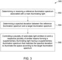
- FIG. 3 there is provided a flow diagram of an embodiment of a method 300 of supplementing a main illuminating light with a supplementary illuminating light from a plurality of solid-state light emitters to illuminate a space according to a target illumination spectrum.
- main illuminating light or “main illumination” is intended to refer to any light used for illuminating a space and whose illumination spectrum can be enhanced, optimized, improved, supported, completed, or otherwise supplemented according to the present techniques.
- the main illuminating light can originate from or be produced by one or more artificial light sources, one or more natural light sources, or a combination of at least one natural light source and at least one artificial light source.
- natural light sources or conditions include sunlight, daylight, nightlight, moonlight, starlight, twilight, lightning, firelight, and a combination thereof.
- Non-limiting examples of artificial light sources include incandescent light sources; fluorescent light sources; high-intensity discharge (HID) light sources, such as mercury vapor, metal halide (MH), high-pressure sodium (HPS), and low-pressure sodium (LPS) light sources; other types of gas-discharge lamp sources; solid-state light sources, such as LED light sources and laser-based solid-state light sources; and non-solid-state laser sources.
- HID high-intensity discharge
- MH metal halide
- HPS high-pressure sodium
- LPS low-pressure sodium
- space is intended to encompass any region, scene, area, surface, environment, target, object, feature, or information of interest which can be illuminated according to the present techniques.
- possible spaces include indoor and outdoor agricultural spaces and facilities, such as greenhouses and other horticultural infrastructures; business and commercial workspaces; public spaces; residential households; industrial facilities; healthcare facilities; and the like.
- supplementary illuminating light or “supplemental illumination” is intended to refer to light emitted by a lighting system including a plurality of solid-state light emitters having different spectral profiles to enhance or supplement the illumination spectrum of the main illuminating light.
- the supplementary illuminating light produced by the plurality of solid-state light emitters is supplemented or added to the main illuminating light to achieve enhanced illumination having a target illumination spectrum.
- solid-state light emitter is intended to refer to any light-emitting device that operates by converting electrical energy into electromagnetic radiation through the recombination of electronic carriers (e.g., electrons and holes) in a light-emitting layer or region.
- the light-emitting layer or region can include, but is not limited to, silicon, silicon carbide, gallium nitride, and/or other semiconductor materials, and may or may not include a substrate, such as a sapphire, silicon, silicon carbide, and/or other microelectronic substrates.
- the solid-state light emitters can include both inorganic and organic light emitters, many of which are known to the skilled person and need not be described in detail herein.
- Non-limiting examples of types of solid-state light emitters include semiconductor light-emitting diodes (LEDs), semiconductor laser diodes, vertical-cavity surface-emitting lasers (VCSELs), other semiconductor light emitting devices or lamps, organic light-emitting diodes (OLEDs), and polymer light-emitting diode (PLEDs).
- LEDs semiconductor light-emitting diodes
- VCSELs vertical-cavity surface-emitting lasers
- OLEDs organic light-emitting diodes
- PLEDs polymer light-emitting diode
- illumination spectrum is intended to refer to the spectral power distribution of an illumination, that is, the distribution of power radiated by an illumination per unit area and per unit wavelength or frequency over a spectral region of the electromagnetic spectrum. It is appreciated that the term “illumination spectrum” can refer to the concentration or amount, as a function or wavelength or frequency, any suitable radiometric or photometric quantity. It is also appreciated that, in general, an illumination spectrum can be described in terms of its absolute intensity level or its relative spectral shape, or both its absolute intensity level and its relative spectral shape. Furthermore, in some embodiments, an illumination spectrum may be characterized by a color temperature, which can range from about 1000 K to about 35 000 K, for example between 1500 K and 8000 K.
- target illumination spectrum is intended to refer to any desired or required illumination spectrum to be achieved according to the present techniques as a result of supplementing the main illuminating light with the supplementary illuminating light emitted by the solid-state-based lighting system.
- the target illumination spectrum can be obtained by adjusting the illumination spectrum of the solid-state-based lighting system to match a difference or discrepancy between the illumination spectrum of the main illuminating light and the target illumination spectrum to be achieved.
- target illumination spectrum can be selected to reproduce or replicate natural light.
- natural light such as sunlight, moonlight, and starlight
- the replicated natural light can be representative of lighting conditions on Earth.
- the lighting conditions can relate or correspond to temporal (e.g., a time of day or a time of year), geographical (e.g., a location on Earth defined in terms of its latitude, longitude, and/or altitude), or meteorological (e.g., climate or weather conditions, such as sunny, rainy, cloudy, overcast, foggy, snowy, stormy, and smoggy) factors and parameters, or combinations of such factors and parameters.
- meteorological e.g., climate or weather conditions, such as sunny, rainy, cloudy, overcast, foggy, snowy, stormy, and smoggy
- the present techniques can use the supplementary illuminating light to fill one or more gaps in the illumination spectrum of the main illuminating light to obtain a target illumination spectrum that is closer to natural lighting conditions.
- the target illumination spectrum may or may not encompass visible light wavelengths and may or may encompass non-visible light wavelengths.
- the present techniques can be used to improve the health, wellness, and/or productivity of plants, animals, or people, for example by transforming a cloudy-day illumination spectrum into a sunny-day illumination spectrum.
- the target illumination spectrum may differ from natural lighting conditions.
- the target illumination spectrum generated according to the present techniques can differ from any actual or observable spectrum of solar radiation on Earth, for example by reducing or excluding spectral components that are considered undesirable and/or enhancing or adding spectral components that are required or considered advantageous.
- the target illumination spectrum can be selected to reproduce or replicate artificial light.
- the replicated artificial light can be representative of a particular type of artificial lighting, such as incandescent lighting, fluorescent lighting, HID lighting, solid-state lighting, or any combination thereof.
- the target illumination spectrum can be selected to provide a combination of natural and artificial lighting.
- the target illumination spectrum may vary or be constant as a function of time over an illumination period during which the method is implemented.
- the target illumination spectrum can be a dynamic lighting scenario that is representative of a diurnal illumination cycle or a portion thereof.
- the scenario timeline can be defined in terms of Earth-based time units (e.g., seconds, minutes, hours, days, weeks, months, years, and the like).
- the duration of the dynamic lighting scenario can be defined based on other time units (e.g., a "day” in the dynamic lighting scenario may be shorter or longer than 24 hours, and a "week” may include less or more than seven days).
- the target illumination spectrum can be determined or selected depending on the application, notably on the nature of the space to be illuminated.
- the target illumination spectrum may be selected from a database and/or determined by user input.
- the target illumination spectrum associated with a given type of light source or application can be stored in memory and retrieved by a control and processing unit of the lighting system used to implement the method.
- the target illumination spectrum can be determined, supplied, or otherwise provided by user input to the control and processing unit of the lighting system.
- the target illumination spectrum can be selected from a plurality of possible target illumination spectra stored in memory.
- possible target illumination spectra can be defined based on a standard illuminant (e.g., A, B, C, or D) or a correlated color temperature (CCT), whether on the Planckian locus or not.
- CCT is a characteristic of visible light, which may not be appropriate to describe target illumination states encompassing non-visible light only.
- the method 300 of Fig. 3 can be implemented using a lighting system such as the ones illustrated in Figs. 4 and 5 , or using another appropriate lighting system.
- Fig. 4 is a schematic representation of a lighting system 10 for supplementing a main illuminating light 100 illuminating a space 102 with a supplementary illuminating light 12 to generate a supplemented illuminating light 104 having a supplemented illumination spectrum 106 that matches a target illumination spectrum 108.
- the main illuminating light 100 originates from an artificial light source 110 and is characterized by a reference illumination spectrum 112, while the target illumination spectrum 108 corresponds to a predetermined sunlight spectrum.
- both the reference illumination spectrum 112 to be supplemented and the target illumination spectrum 108 to be achieved can correspond to any particular type of lighting source or combination of lighting sources-whether natural and/or artificial-appropriate or required for a particular application.
- the lighting system 10 in Fig. 4 generally includes a beam emission assembly 114, a beam combining assembly 17, a control and processing unit 116, a reference spectrum sensor 118, and a supplemented spectrum sensor 120. These and other possible components of the lighting system 10 are described in greater detail below.
- the beam emission assembly 114 includes a plurality of solid-state light emitters 14 configured to emit a respective plurality of emitter beams 16 to form the supplementary illuminating light 12.
- the plurality of emitter beams 16 have a respective plurality of emitter spectra, each of which characterized by an intensity level and a spectral shape or profile.
- the emitter spectra of the emitter beams 16 together define a supplementary illumination spectrum 122 of the supplementary illuminating light 12.
- the beam combining assembly 17 is configured to receive the emitter beams 16 produced by the plurality of solid-state light emitters 14 and combine them into the supplementary illuminating light 12 to illuminate the space 102 together with the main illuminating light 100.
- the supplementary illuminating light 12 supplements the main illuminating light 100 to form the supplemented illuminating light 104.
- the control and processing unit 116 is configured for controlling, monitoring, and/or coordinating, at least partly, the functions and operations of various components of the lighting system 10, such as, for example, the beam emission assembly 114, the beam combining assembly 17, the reference spectrum sensor 118, and the supplemented spectrum sensor 120.
- the control and processing unit 116 can also be configured to process and analyze sensor data measured by the reference spectrum sensor 118 and the supplemented spectrum sensor 120.
- the control and processing unit 116 can also be referred to as a "computer device".
- control and processing unit 116 can be configured to perform the following functions: determine or receive the reference illumination spectrum 112 associated with the main illuminating light 100; determine a spectral deviation between the reference illumination spectrum 112 and the target illumination spectrum 108; and control the plurality of solid-state light emitters 14 by adjusting the plurality of emitter spectra to match the supplementary illumination spectrum 122 of the supplementary illuminating light 12 to the spectral deviation and illuminate the space 102 according to the target illumination spectrum 108. That is, if the supplementary illumination spectrum 122 matches the spectral deviation, then the supplemented illumination spectrum 106 matches the target illumination spectrum 108.
- the control and processing unit 116 can be implemented in hardware, software, firmware, or any combination thereof, and be connected to various components of the lighting system 10 via wired and/or wireless communication links and ports to send and/or receive various types of electrical signals, such as timing and control signals, measurement signals, and data signals.
- the control and processing unit 116 may be controlled by direct user input or by programmed instructions, and may include an operating system for controlling and managing various functions of the lighting system 10. Depending on the application, the control and processing unit 116 can be fully or partially integrated with or physically separate from the other hardware components of the lighting system 10.
- the control and processing unit 116 generally includes a processor 124 and a memory 126.
- the processor 124 may be able to execute computer programs, also generally known as commands, instructions, functions, processes, software codes, executables, applications, and the like.
- the term "computer program” is used in a generic sense to refer to any type of computer code (e.g. software or microcode) that can be employed to program the processor 124.
- the processor 124 may include a plurality of processing units. Such processing units may be physically located within the same device, or the processor 124 may represent processing functionality of a plurality of devices operating in coordination.
- the control and processing unit 116 may include a main processor configured to provide overall control and one or more secondary processors configured for dedicated control operations or signal processing functions.
- the processor 124 may include or be part of a computer; a microprocessor; a microcontroller; a coprocessor; a central processing unit (CPU); an image signal processor (ISP); a digital signal processor (DSP) running on a system on a chip (SoC); a single-board computer (SBC); a dedicated graphics processing unit (GPU); a special-purpose programmable logic device embodied in hardware device, such as, for example, a field-programmable gate array (FPGA) or an application-specific integrated circuit (ASIC); a digital processor; an analog processor; a digital circuit designed to process information; an analog circuit designed to process information; a state machine; and/or other mechanisms configured to electronically process information and to operate collectively as a processor.
- processor and “controller” should not be construed as being limited to a single processor or a single controller, and accordingly, any known processor or controller architecture may be used.
- the memory 126 which can also be referred to as a computer readable storage medium, is capable of storing computer programs and other data to be retrieved by the processor 124.
- computer readable storage medium and “computer readable memory” are intended to refer to a non-transitory and tangible computer product that can store and communicate executable instructions for the implementation of various steps of the methods disclosed herein.
- the computer readable memory can be any computer data storage device or assembly of such devices, including random-access memories (RAMs); dynamic RAMs; read-only memories (ROMs); magnetic storage devices, such as hard disk drives, solid state drives, floppy disks, and magnetic tapes; optical storage devices, such as compact discs (e.g., CDs and CDROMs), digital video discs (DVDs), and Blu-Ray TM discs; flash drive memories; and/or other non-transitory memory technologies.
- RAMs random-access memories
- ROMs read-only memories
- magnetic storage devices such as hard disk drives, solid state drives, floppy disks, and magnetic tapes
- optical storage devices such as compact discs (e.g., CDs and CDROMs), digital video discs (DVDs), and Blu-Ray TM discs
- flash drive memories and/or other non-transitory memory technologies.
- a plurality of such storage devices may be provided, as can be appreciated by those skilled in the art.
- the computer readable memory may be associated with
- the reference spectrum sensor 118 and the supplemented spectrum sensor 120 can be embodied by appropriate spectrally resolved sensor or combination of spectrally resolved sensors configured for collecting and measuring information, particularly real-time information, about the reference illumination spectrum 112 of the main illuminating light 100 and the supplemented illumination spectrum 106 of the supplemented illuminating light 104, respectively.
- the term "spectrally resolved sensor” is intended to refer to any device or combination of devices configured for measuring or detecting a spectrally dependent response (e.g., as a function of frequency or wavelength over a certain spectral range) of an input signal.
- Non-limiting examples of spectrally resolved sensors or detectors that can be used for the reference spectrum sensor 118 and the supplemented spectrum sensor 120 include spectrometers, photometers (e.g., lux meters and PAR meters), photometric analyzers, on-chip multispectral sensors, phototransistors, pyrheliometers, and goniophotometers. Based on the measured spectra information, the control signals supplied to the plurality of solid-state light emitters 14 can be adjusted, for example in real time, to ensure that the match between the supplemented illumination spectrum 106 and the target illumination spectrum 108 persists over time during the operation of the lighting system 10.
- a supplementary spectrum sensor may also or alternatively be provided for collecting and measuring information about the supplementary illumination spectrum 122 of the supplementary illuminating light 12.
- a plurality of reference spectrum sensors, and/or a plurality of supplemented spectrum sensors, and/or a plurality of supplementary spectrum sensors may be provided.
- a plurality of reference spectrum sensors may be provided to measure the reference illumination spectrum of the main illuminating light.
- the reference spectrum sensors may be disposed at different locations within the illuminated space.
- the reference illumination spectrum may be determined by combining, according to different schemes, spectrum data measured from the plurality of reference spectrum sensors.
- the measured spectra associated with different reference spectrum sensors may be given identical or different weights in the determination of the reference illumination spectrum of the main illuminating light.
- a plurality of supplemented spectrum sensors may be provided to measure the supplemented illumination spectrum of the supplemented illuminating and assess whether it matches the target illumination spectrum.
- the supplemented spectrum sensors may be disposed at different locations within the illuminated space.
- the supplemented illumination spectrum may be determined by combining, according to different schemes, spectrum data measured from the plurality of supplemented spectrum sensors.
- the measured spectra associated with different supplemented spectrum sensors may be given identical or different weights in the determination of the supplemented illumination spectrum to be compared with the target illumination spectrum.
- a reference spectrum sensor may be used to obtain information about a main illuminating light, and this information can be sent to more than one lighting system, each lighting system including a set of solid-state light emitters and configured to provide its own supplementary illuminating light 12 according to a given target illumination spectrum, where different lighting systems may have different or identical target illumination spectra, as the case may be.
- the target illumination spectrum associated with each lighting system may be defined according to the spatial location of the space illuminated by the lighting system.
- the lighting system 10 of Fig. 5 is configured for supplementing a main illuminating light with a supplementary illuminating light 12 to illuminate a space according to a target illumination spectrum.
- the supplementary illuminating light 12 has a supplementary illumination spectrum that matches a spectral discrepancy between a reference illumination spectrum of a main illumination and a target illumination spectrum to be achieved.
- the lighting system 10 includes a lamp 11 having a plurality of solid-state light emitters 14 1 , 14 2 , ..., 14 n (hereinafter referred to generally and collectively as solid-state light emitters 14).
- the solid-state light emitters 14 can be embodied by LEDs.
- the number of solid-state light emitters 14 in the lighting system 10 can range between six and twenty, for example between eight and sixteen, although some embodiments can be operated outside this range.
- Each solid-state light emitter 14 1 , 14 2 , ..., 14 n is configured to emit an emitter beam 16 1 , 16 2 , ..., 16 n (hereinafter referred to generally and collectively as emitter beams 16) having an individual emitter spectrum.
- the individual emitter spectra of the emitter beams 16 collectively cover a spectral region encompassing the target illumination spectrum to be generated.
- one or more of the solid-state light emitters 14 may be configured to emit visible light of a certain color including, but not limited to, violet, blue, cyan, green, yellow, amber, orange, red, and white.
- the solid-light emitters 14 can include at least one colored-light emitter and at least one white-light emitter.
- one or more of the solid-state light emitters 14 may be configured to emit infrared radiation or ultraviolet radiation.
- the emitter spectrum of a solid-state light emitter 14 may have a center wavelength and spectral range such that it partially overlaps, for example at full width at half maximum (FWHM) or higher, with a spectrally adjacent individual emitter spectrum of another one of the solid-state light emitters 14.
- FWHM is understood in the art to mean the extent of a function, given by the difference between the two extreme values of the independent variable at which the dependent variable is equal to half of its maximum value.
- the above condition may be achieved with solid-state light emitters 14 having individual emitter spectra characterized by an average FWHM of about 30 nm and a separation between adjacent center wavelengths of at most 15 nm.
- each one of the solid-state light emitters 14 may have a unique emitter spectrum, or a subset of the solid-state light emitters 14 may have identical emitter spectra.
- the lighting system 10 also includes a beam combining assembly 17.
- the beam combining assembly 17 is configured to combine the emitter beams 16 emitted by the solid-state light emitters 14 into an output light beam that forms the supplementary illuminating light 12.
- the supplementary illuminating light 12 has a supplementary illumination spectrum defined from a combination of the individual emitter spectra of the emitter beams 16 provided by the plurality of solid-state light emitters 14.
- the beam combining assembly 17 can include any optical, mechanical, or optomechanical components, or combination of such components, configured to appropriately combine the plurality of emitter beams 16 into the supplementary illuminating light 12.
- the beam combining assembly 17 includes a support structure 40 on which the solid-state light emitters 14 are mounted, and preferably positioned such that the emitter beams 16 are emitted toward a common diffusing plane 19.
- the beam combining assembly 17 also include a diffuser 18 extending along the diffusing plane 19.
- the diffuser 18 may be embodied by any optical component or combination of optical components configured to blend the emitter beams 16 into an output light beam defining the supplementary illuminating light 12.
- the diffuser 18 can be embodied by sandblasted glass or plastic, or other types of light-mixing optics.
- the diffuser 18 may be oriented to direct the supplementary illuminating light 12 onto an object or surface in the space to be illuminated.
- the beam combining assembly 17 may not include components to blend the emitter beams 16 from the individual solid-state light emitters 14 together, but instead may simply direct the emitter beams 16 along a common optical path.
- the emitter beams 16 emitted by the solid-state light emitter 14 may be directed by angled reflectors (not shown).
- filters and/or coatings may be provided on the solid-state light emitters 14 and/or the diffuser 18 to spectrally condition the supplementary illuminating light 12 by adding, modifying, reducing, and/or eliminating spectral components of the individual emitter spectra.
- the lamp 11 can further include a local controller 24 to control, at least partly, the operation of the solid-state light emitters 14.
- the local controller 24 may be a processor or a microcontroller, non-limiting examples of which include an ATmega328 microcontroller, an Intel MCS-51 microcontroller, a PIC microcontroller, a Texas Instruments MSP430 microcontroller, and an ARM processor.
- the local controller 24 may send, as input signals, a set of control or driving parameters to a set of emitter drivers 26 1 , 26 2 , ..., 26 n (hereinafter referred to generally and collectively as emitter drivers 26), each associated with a corresponding one of the solid-state light emitters 14 1 , 14 2 , ..., 14 n .
- emitter drivers 26 can supply a driving current to the corresponding solid-state light emitter 14 to cause the solid-state light emitter 14 to generate the corresponding emitter beam 16.
- a solid-state emitter 14 such as an LED generates light when a current is driven across its p-n junction.
- the intensity of the light generated by the LED is thus correlated to the amount of current driven through the diode.
- the local controller 24 controls the solid-state light emitters 14 according to a pulse-width modulation (PWM) scheme, which is a known method of controlling the current driven through an LED to achieve desired intensity and/or color mixing.
- PWM pulse-width modulation
- a PWM scheme alternately pulses the LED to a full-current "ON" state, followed by a zero-current "OFF” state.
- the average luminous power emitted by the LEDs can be proportionally increased or decreased by controlling the variation of the duty cycle between 0% and 100%.
- the intensity and the temperature of the LEDs may thus be controlled by the PWM signals supplied to the plurality of emitter drivers 26.
- Each emitter driver 26 then sends its own PWM current pulse to its associated solid-state light emitter 14.
- the luminous intensity of the resultant emitter beams 16 may be individually adjusted by independently applying particular drive currents to the respective solid-state light emitters 14 according to the driving signals supplied from the corresponding emitter driver 26.
- the intensity of light from each solid-state light emitter 14 may be adjusted to power the solid-state light emitter 14 high or low for generating the supplementary illuminating light 12.
- the driving signals from each emitter driver 26 supplied to the corresponding solid-state light emitter 14 are individually controlled, so that the resulting supplementary illumination spectrum of the supplementary illuminating light 12 matches the spectral deviation between the reference illumination spectrum of the main illuminating light and the target illumination spectrum to be achieved.
- the frequency of the PWM signals may be adjustable from 25 Hz to 100 kHz, for example between 100 Hz and to 10 kHz, for implementing certain lighting functions, such as a dimming function.
- a high PWM frequency may be employed, for example ranging between 150 Hz and 1 kHz), such that the on-and-off flickering of the solid-state light emitters 14 is generally not perceptible to the naked eye.
- the intensities of the individual emitter spectra of the emitter beams 16 emitted by the solid-state light emitters 14 may be dependent on different working temperatures and different PWM values. It is appreciated, however, that the driving of the solid-state light emitters 14 by the drivers 26 is not limited to a PWM approach, and that other driving schemes may be used depending on the application. In one variant, linear current signals may be provided to the solid-state light emitters 14.
- the current signals provided to the solid-state light emitters 14 may be controlled using built-in mathematical equations and a light-emitter parameter database containing information such as luminous efficacy, intensity-temperature relationships, color shift-temperature relationships, the eight nominal CCT quadrangles, and the like, to individually and proportionally control the intensities of the solid-state light emitters 14.
- the lighting system 10 includes, in addition to the local controller 24 provided proximate or integrated to the lamp 11, a separate main controller 50.
- the main controller 50 may be remotely located and configured to control a plurality of lamps 11 such as the one shown in Fig. 5 .
- a single controller may be associated with a single lamp and perform all the associated controlling functions.
- the method 300 can include a step 302 of determining or receiving, for example by a processor, a reference illumination spectrum associated with the main illuminating light.
- a reference illumination spectrum associated with the main illuminating light.
- the main illuminating light can emanate from one or more natural light sources, one or more artificial light sources, or a combination of at least one natural light source and at least one artificial light source.
- the phrase "determining or receiving a reference illumination spectrum" is used broadly to encompass, without being limited to, providing, acquiring, making available for use, obtaining, assessing, accessing, supplying, assigning, retrieving, setting, selecting, computing, calculating, and deriving the reference illumination spectrum.
- two main classes of embodiments of determining or receiving the reference illumination spectrum may be considered.
- the two classes of embodiments differ depending on whether the determined or received reference illumination spectrum is established based on information or data about main illuminating light obtained prior to or while performing the method 300.
- the determining or receiving step 302 can involve retrieving or receiving a predefined or predetermined reference illumination spectrum, for example from a storage location.
- the reference illumination spectrum may be stored as an array of numbers that represent the relative or absolute spectral power distribution of the main illuminating light as a function of wavelength, frequency, or another suitable spectral parameter.
- the reference illumination spectrum can be retrieved or received from various types of storage locations, such as a simple file, a database, a virtual library, a storage medium, a local memory system, a server, a cloud computing resource, a network, a peer-to-peer structure, a blockchain, and so forth.
- the reference illumination spectrum can be selected from a database containing a plurality of predefined illumination spectra, as either one or a combination of one or more of the plurality of predefined illumination spectra.
- the reference illumination spectrum can be a pre-programmed or pre-calibrated illumination spectrum stored in a memory of the artificial light source.
- the main illuminating light may originate from a plurality of artificial light sources. For example, some horticultural applications use a combination of HPS lamps with warm white, cool white, red, and blue LEDs. In such a case, the reference illumination spectrum can be obtained as a combination of predetermined illumination spectra associated with the plurality of artificial light sources.
- the reference illumination spectrum may also be a preset or known illumination spectrum, which can be retrieved or received from a simple file, a database, a virtual library, or a storage medium.
- the reference illumination spectrum can be determined by a processor, based on one or more predictive or condition-dependent factors related to the space to be illuminated, that is, where and when the method 300 is to be carried out.
- predictive or condition-dependent factors can include geographical information (e.g., latitude, longitude, and altitude), temporal information (e.g., with respect to the time of day or the time of year), current and/or forecast weather information, pollution level, the tilt of the Earth with respect to the Sun, turbidity, albedo, ozone level, atmospheric absorption, air density, and the like.
- Information regarding one or more predictive or condition-dependent factors can be transmitted through suitable wired and/or wireless communication channels to a processor.
- the processor can determine a reference illumination spectrum associated with the main illuminating light, for example by calculation or selection of a best match among a plurality of possible illumination spectra stored in a spectrum library or database.
- the determined or received reference illumination spectrum can be updated over time during the implementation of the method 300, as new information about relevant predictive factors, for example related to current or forecast weather conditions, becomes available.
- dedicated sensors or instruments may be provided for carrying out measurements, possibly in real-time, that can be processed to convey information about current or forecast weather conditions, which in turn can be used to update the reference illumination spectrum over time.
- sensing devices may be provided inside a greenhouse to monitor cloud coverage and measure cloud coverage data that can be used to determine real-time information about the reference illumination spectrum.
- the determining or receiving step 302 can involve using sensors and detectors to gather information about the reference illumination spectrum associated with the main illuminating light.
- the determining or receiving step 302 can include using a spectrally resolved sensor to measure a spectral response of the main illuminating light, and determining the reference illumination spectrum from the measured spectral response of the main illuminating light.
- sensors and detectors that can be used according to the present techniques include spectrometers, photometers (e.g., lux meters and PAR meters), photometric analyzers, on-chip multispectral sensors, phototransistors, pyrheliometers, and goniophotometers.
- the method 300 also includes a step 304 of determining a spectral deviation between the reference illumination spectrum and the target illumination spectrum.
- spectral deviation is a broad term that is intended to refer to a difference, a discrepancy, a divergence, or a variation, over a certain spectral range, between the reference illumination spectrum of the main illuminating light and the target illumination spectrum to be achieved. That is, the spectral deviation is meant to represent the amount or degree by which the reference illumination spectrum differs from the target illumination spectrum.
- the supplementary illuminating light produced by the plurality of solid-state light emitters supplements the main illuminating light and has a supplementary illumination spectrum that is adjusted to compensate for the spectral deviation between the reference illumination spectrum and the target illumination spectrum.
- the spectral deviation spectrum may vary or be constant as a function of time over an illumination period during which the method is implemented.
- the reference illumination spectrum and the target illumination spectrum can deviate from each other in terms of their intensity levels or their spectral shapes, or both their intensity levels and their spectral shapes.
- the spectral deviation between the reference illumination spectrum and the target illumination spectrum can be obtained by subtracting, canceling, or otherwise removing the reference illumination spectrum from the target illumination spectrum over a certain spectra range.
- the spectral range in which the spectral deviation is nonzero or nonnegligible may encompass all or nearly all of the reference illumination spectrum.
- the spectral range in which the spectral deviation is nonzero or nonnegligible may encompass only a limited portion of the reference illumination spectrum.
- the reference illumination spectrum may extend throughout the visible region of the electromagnetic spectrum, while the spectral deviation may nonzero or nonnegligible only in a portion of the visible region, such as between about 400 nm and 550 nm.
- the supplementary illumination spectrum of the supplementary illuminating light is narrower than the reference illumination spectrum of the main illuminating light.
- the method 300 further includes a step 306 of controlling the plurality of solid-state light emitters to emit a respective plurality of emitter beams that forms the supplementary illuminating light and illuminates the space along with the main illuminating light.
- the plurality of emitter beams has a respective plurality of emitter spectra that defines a supplementary illumination spectrum of the supplementary illuminating light.
- the individual emitter spectrum associated with each solid-state light emitter is assumed to be known prior to starting the method 300.
- the step 306 of controlling the plurality of solid-state light emitters includes adjusting the plurality of emitter spectra to match the supplementary illumination spectrum of the supplementary illuminating light to the spectral deviation and illuminate the space according to the target illumination spectrum.
- the expression "adjusting the plurality of emitter spectra” is intended to encompass adjusting the plurality of emitter spectra individually, collectively, or partly individually and partly collectively. This expression is also intended to encompass adjusting each emitter spectra in terms of its absolute intensity level or its relative spectral shape, or both its intensity level and its spectral shape. It is appreciated that achieving a match between the supplementary illumination spectrum of the supplementary illuminating light and the spectral deviation between the reference illumination spectrum and the target illumination spectrum causes the supplemented illumination spectrum of the supplemented illuminating light to match the target illumination spectrum.
- the solid-state light emitters are configured to generate missing, lacking, or insufficiently represented spectral components of the reference illumination spectrum, such that the superposition or combination of the reference illumination spectrum and the supplementary illumination spectrum yields a supplemented illumination spectrum that matches the target illumination spectrum.
- the spatial dependence of the magnitude of each of the reference and supplementary illumination spectra may have to be considered for the supplemented illumination spectrum to match the target illumination spectrum at the desired location within the space.
- the terms “match”, “matching” and “matched” are meant to encompass not only an exact or identical match between the supplementary illumination spectrum of the supplementary illuminating light and the spectral deviation, likewise between the supplemented illumination spectrum of the supplemented illuminating light and the target illumination spectrum, but also a substantial, approximate, subjective, sufficient, or acceptable match, as well as a higher or best match among a plurality of matching possibilities.
- the supplemented illumination spectrum may be either the same or within some predetermined tolerance of the target illumination spectrum, for example within a five to ten percent error, where the error can be defined in any suitable form.
- the present techniques contemplate not only scenarios where the match between the supplemented illumination spectrum and the target illumination spectrum is absolute, but also scenarios where the match is relative (i.e., in terms of normalized spectra).
- the supplemented illumination spectrum may be measured at a plurality of distinct locations within the illuminated space. In such embodiments, it may be determined that the supplemented illumination spectrum matches the target illumination spectrum if a matching criteria is satisfied at least at a predetermined sufficient number of the plurality of locations within the space.
- the step 306 of controlling the plurality of solid-state light emitters can include adjusting relative intensity levels of the emitter beams emitted by the plurality of solid-state light emitters to generate the supplementary illuminating light to match the spectral deviation.
- controlling the plurality of solid-state light emitters can include determining or receiving a set of control parameters for the plurality of solid-state light emitters, and driving the plurality of solid-state light emitters according to the set of control parameters to generate the supplementary illuminating light in accordance with the spectral deviation determined at step 304.
- the set of control parameters can be a set of individual PWM signals with which to drive the solid-state light emitters.
- the determination of the set of control parameters for the plurality of solid-state light emitters that produces a supplementary illuminating light having a supplementary illumination spectrum that matches the determined spectral deviation can be based on pre-calibration, spectrum fitting techniques, or other approaches that rely on the individual emitter spectra of the plurality of solid-state light emitters as known input parameters.
- the set of control parameters with which to drive the plurality of solid-state light emitters to achieve the desired supplementary illumination spectrum can be stored in a non-volatile memory accessible to the controller that drives the solid-state light emitters.
- the desired supplementary illumination spectrum can be recalculated, and its value stored in memory.
- the spectral deviation between the target illumination spectrum and the reference illumination spectrum can also be determined in real or near real time.
- the controller can adjust the set of control parameters for the plurality of solid-state light emitters accordingly.
- the step 304 of determining the spectral deviation between the reference illumination spectrum and the target illumination spectrum can include monitoring the spectral deviation for changes over time, for example by continuous or intermittent real-time measurements of the reference illumination spectrum, the supplementary illumination spectrum, and/or a combination of the reference illumination spectrum and the supplementary illumination spectrum (i.e., the supplemented illumination spectrum).
- the step 306 of controlling the plurality of solid-state light emitters can include, upon detection that the spectral deviation has changed, adjusting the plurality of emitter spectra to keep the supplementary illumination spectrum matched to the spectral deviation. It is appreciated that the plurality of emitter spectra may be adjusted only if the detected change in the spectral deviation exceeds a certain threshold.
- the set of control parameters can be adjusted in real or near real time, according to different refresh rates and different update thresholds.
- real time and “near real time” are used as practical terms that depend on the particular implementation of the method 300. These terms of degree generally refer to the fact that the method 300 can sense, determine and adjust variable illuminating conditions seamlessly, with negligible or insignificant time lag on the typical scale of human perception.
- the method 300 can include a step of monitoring the supplemented illuminating light by measuring, in real or near real time or, its illumination spectrum to verify that it does indeed match the target illumination spectrum (e.g., using spectrally resolved sensors, such as supplemented spectrum sensor 120 in Fig. 4 ). That is, the monitoring of the supplemented illumination spectrum and the finding of any mismatch relative to the desired target illumination spectrum can provide a feedback signal.
- This feedback signal can be supplied to the controller to further adjust the set of control parameters driving the solid-state light emitters to correct or modify the supplementary illumination spectrum of the supplementary illuminating light for attempting to relieve, compensate, or reduce the observed mismatch.
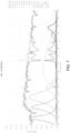
- FIGs. 6 and 7 some capabilities of the present techniques in terms of supplementing the spectral content of a main illuminating light with solid-state light emitters in order to achieve a target illumination spectrum are illustrated.
- Each of Figs. 6 and 7 is a graph showing a number of illumination spectra plotted as a function of wavelength between 400 and 700 nm. The illustrated spectra are as follows.
- REF a reference illumination spectrum of a main illuminating light, which was simulated based on known information about the main illuminating light.
- TARGET a target illumination spectrum to be achieved, which was predetermined by user input.
- RECT a desired supplementary illumination spectrum of a supplementary illuminating light to be generated by a set of sixteen LEDs, which was obtained by subtracting the reference illumination spectrum ("REF”) from the target illumination spectrum ("TARGET”).
- LED_00” to “LED_15” individual emitter spectra of sixteen emitter beams generated by the set of sixteen LEDs, whose relative intensities were calculated based on experimentally characterized LED spectral shapes, in an attempt to fulfill the condition that their sum yield an illumination spectrum corresponding to the desired illumination spectrum ("RECT").
- FINAL a supplemented illumination spectrum
- REF reference illumination spectrum
- LED_00 the sum of the individual emitter spectra
- the main illuminating light is sunlight on a cloudy day and the target illumination spectrum ("TARGET") to be achieved corresponds to sunny conditions at around 10 a.m.
- the main illuminating light is produced by a conventional HPS lamp and the target illumination spectrum ("TARGET") to be achieved corresponds to CIE Standard Illuminant D65 (CCT: 6500 K).
- CIE Standard Illuminant D65 CCT: 6500 K.
- the sum of the individual emitter spectra from the sixteen LEDs (“LED_00” to “LED_15”) yields, when combined to the reference illumination spectrum (“REF”) associated with the main illuminating light, a supplemented illumination spectrum (“FINAL) that closely matches the target illumination spectrum (“TARGET”).
- the lighting system can include a plurality of solid-state light emitters, for example LEDs.
- the plurality of solid-state light emitters is configured to emit a respective plurality of emitter beams forming the supplementary illuminating light and illuminating the space along with the main illuminating light.
- the plurality of emitter beams has a respective plurality of emitter spectra together defining a supplementary illumination spectrum of the supplementary illuminating light.
- the lighting system can also include a beam combining assembly configured to combine the emitter beams emitted by the plurality of solid-state light emitters into the supplementary illuminating light for illumination of the space together with the main illuminating light.
- the method can include steps of determining or receiving a reference illumination spectrum associated with the main illuminating light; determining a spectral deviation between the reference illumination spectrum and the target illumination spectrum; and controlling the plurality of solid-state light emitters by adjusting the plurality of emitter spectra to match the supplementary illumination spectrum of the supplementary illuminating light to the spectral deviation and illuminate the space according to the target illumination spectrum.
- a non-transitory computer readable storage medium having stored thereon computer executable instructions that, when executed by a processor, cause the processor to perform a method of controlling a lighting system as described herein.
- the method can be performed for supplementing a main illuminating light with a supplementary illuminating light from a plurality of solid-state light emitters of the lighting system to illuminate a space according to a target illumination spectrum.
- computer readable storage medium and “computer readable memory” are intended to refer to a non-transitory and tangible computer product that can store and communicate executable instructions for the implementation of various steps of the method disclosed herein.
- the computer readable memory can be any computer data storage device or assembly of such devices, various non-limiting examples of which are mentioned above. A plurality of such storage devices may be provided, as can be appreciated by those skilled in the art.
- the computer readable memory may be associated with, coupled to, or included in a computer or processor configured to execute instructions contained in a computer program stored in the computer readable memory and relating to various functions associated with the computer.
- a computer device for use with a lighting system.
- the computer device can include a processor and a non-transitory computer readable storage medium operatively coupled to the processor and having stored thereon computer readable instructions that, when executed by a processor, cause the processor to perform various steps of the methods disclosed herein.
Landscapes
- Circuit Arrangement For Electric Light Sources In General (AREA)
Claims (12)
- Verfahren (300) zur Ergänzung eines Hauptbeleuchtungslichts (100) mit einem Ergänzungsbeleuchtungslicht (12) aus einer Vielzahl von Festkörperlichtemittern (14), um einen Raum (102) entsprechend einem Zielbeleuchtungsspektrum (108) zu beleuchten, wobei das Verfahren (300) umfasst:Bestimmen oder Empfangen (302) eines Referenzbeleuchtungsspektrums (112), das mit dem Hauptbeleuchtungslicht (12) assoziiert ist;Bestimmen (304) einer Spektralabweichung zwischen dem Referenzbeleuchtungsspektrum (112) und dem Zielbeleuchtungsspektrum (108); undSteuern (306) der Vielzahl von Festkörperlichtemittern (14), um eine jeweilige Vielzahl von Emitterstrahlen (16) zu emittieren, die das Ergänzungsbeleuchtungslicht (12) bilden und den Raum (102) mit dem Hauptbeleuchtungslicht (100) beleuchten, wobei die Vielzahl der Emitterstrahlen (16) eine jeweilige Vielzahl von Emitterspektren aufweist, die zusammen ein Ergänzungsbeleuchtungsspektrum (122) des Ergänzungsbeleuchtungslichts (12) definieren, wobei das Steuern Einstellen der Vielzahl von Emitterspektren umfasst, um das Ergänzungsbeleuchtungsspektrum (122) an die Spektralabweichung anzupassen und den Raum (102) entsprechend dem Zielbeleuchtungsspektrum (108) zu beleuchten,dadurch gekennzeichnet, dass:
das Bestimmen (304) der Spektralabweichung zwischen dem Referenzbeleuchtungsspektrum (112) und dem Zielbeleuchtungsspektrum (108) Überwachen der Spektralabweichung im Zeitverlauf auf Veränderungen umfasst, und wobei Einstellen der Vielzahl von Emitterspektren umfasst, dass bei Detektierung, dass sich die Spektralabweichung verändert hat, die Vielzahl der Emitterspektren eingestellt wird, um das Ergänzungsbeleuchtungsspektrum (122) an die Spektralabweichung angepasst zu halten, wobei das Überwachen der Spektralabweichung Durchführen von kontinuierlichen oder intermittierenden Echtzeitmessungen des Referenzbeleuchtungsspektrums (112), des Ergänzungsbeleuchtungsspektrums (122) oder sowohl des Referenzbeleuchtungsspektrums (112) als auch des Ergänzungsbeleuchtungsspektrums (122) umfasst. - Verfahren (300) nach Anspruch 1, wobei das Hauptbeleuchtungslicht (12) seinen Ursprung in einer oder mehreren natürlichen Lichtquellen hat.
- Verfahren (300) nach Anspruch 1 oder 2, des Weiteren umfassend Auswählen des Zielbeleuchtungsspektrums (108), um natürliches Licht zu replizieren, Auswählen des Zielbeleuchtungsspektrums (108), um künstliches Licht zu replizieren, oder Auswählen des Zielbeleuchtungsspektrums (108), so dass es einer Kombination aus natürlichem Licht und künstlichem Licht entspricht.
- Verfahren (300) nach einem der Ansprüche 1 bis 3, wobei das Zielbeleuchtungsspektrum (108) als Funktion der Zeit über eine Beleuchtungsperiode konstant ist, oder wobei das Zielbeleuchtungsspektrum (108) als Funktion der Zeit über eine Beleuchtungsperiode variiert.
- Verfahren (300) nach einem der Ansprüche 1 bis 4, wobei das Zielbeleuchtungsspektrum (108) mindestens teilweise basierend auf einer Auswahl aus einer Datenbank bestimmt wird.
- Verfahren (300) nach einem der Ansprüche 1 bis 5, wobei das Zielbeleuchtungsspektrum (108) mindestens teilweise basierend auf Benutzereingabe bestimmt wird.
- Verfahren (300) nach einem der Ansprüche 1 bis 6, wobei das Zielbeleuchtungsspektrum (108) Wellenlängen des sichtbaren Lichts umfasst, Wellenlängen außerhalb des sichtbaren Lichts umfasst, oder eine Farbtemperatur im Bereich von etwa 1500 K bis etwa 8000 K hat.
- Verfahren (300) nach einem der Ansprüche 1 bis 7, wobei Bestimmen oder Empfangen (302) des Referenzbeleuchtungsspektrums (108) Bestimmen des Referenzbeleuchtungsspektrums (108) basierend auf einem oder mehreren prädiktiven Faktoren umfasst, die mit dem zu beleuchtenden Raum in Beziehung stehen, wobei der eine oder die mehreren prädiktiven Faktoren auf geografischen Informationen, zeitlichen Informationen, Wetterinformationen oder einer Kombination davon basieren.
- Verfahren (300) nach einem der Ansprüche 1 bis 8, wobei Einstellen der Vielzahl der Emitterspektren individuelles Einstellen eines Intensitätsniveaus von jedem der Emitterspektren umfasst.
- Leuchtsystem (10) zur Ergänzung eines Hauptbeleuchtungslichts (100) mit einem Ergänzungsbeleuchtungslicht (12), um einen Raum (102) entsprechend einem Zielbeleuchtungsspektrum (108) zu beleuchten, wobei das Leuchtsystem (10) umfasst:eine Vielzahl von Festkörperlichtemittern (14), die ausgestaltet ist, um eine jeweilige Vielzahl von Emitterstrahlen (16) zu emittieren, die das Ergänzungsbeleuchtungslicht (12) bilden, und den Raum (102) mit dem Hauptbeleuchtungslicht (100) zu beleuchten, wobei die Vielzahl der Emitterstrahlen (16) eine jeweilige Vielzahl von Emitterspektren aufweist, die zusammen ein Ergänzungsbeleuchtungsspektrum (122) des Ergänzungsbeleuchtungslichts (12) definiert; undeine Steuer- und Verarbeitungseinheit (116), die funktionell an die Vielzahl der Festkörperlichtemitter (14) gekoppelt ist, wobei die Steuer- und Verarbeitungseinheit (116) ausgestaltet ist zum:Bestimmen oder Empfangen eines Referenzbeleuchtungsspektrums (112), das mit dem Hauptbeleuchtungslicht (100) assoziiert ist;Bestimmen einer Spektralabweichung zwischen dem Referenzbeleuchtungsspektrum (112) und dem Zielbeleuchtungsspektrum (108); undSteuern der Vielzahl von Festkörperlichtemittern (14), indem die Vielzahl der Emitterspektren eingestellt wird, um das Ergänzungsbeleuchtungsspektrum (122) an die Spektralabweichung anzupassen und den Raum (102) entsprechend dem Zielbeleuchtungsspektrum (108) zu beleuchten,dadurch gekennzeichnet, dass:
die Steuer- und Verarbeitungseinheit (116) ausgestaltet ist, um die Spektralabweichung im Zeitverlauf auf Veränderungen zu überwachen, und bei Detektierung, dass sich die Spektralabweichung verändert hat, die Vielzahl von Emitterspektren einzustellen, um das Ergänzungsbeleuchtungsspektrm (122) an die Spektralabweichung angepasst zu halten, wobei das Leuchtsystem (10) des Weiteren mindestens einen spektral aufgelösten Sensor (120) umfasst, um kontinuierliche oder intermittierende Echtzeitmessungen des Referenzbeleuchtungsspektrums (112), des Ergänzungsbeleuchtungsspektrums (122) oder sowohl des Referenzbeleuchtungsspektrums (112) als auch des Ergänzungsbeleuchtungsspektrums (122) durchzuführen, wobei die Steuer- und Verarbeitungseinheit (116) ausgestaltet ist, um die Spektralabweichung im Zeitverlauf basierend auf den kontinuierlichen oder intermittierenden Echtzeitmessungen auf Veränderungen zu überwachen. - Leuchtsystem (10) nach Anspruch 10, wobei die Steuer- und Verarbeitungseinheit (116) ausgestaltet ist, um das Zielbeleuchtungsspektrum (108) als zeitkonstante Menge über eine Beleuchtungsperiode auszuwählen, oder um das Zielbeleuchtungsspektrum (108) als zeitvariierende Menge über eine Beleuchtungsperiode auszuwählen.
- Leuchtsystem (10) nach Anspruch 10 oder 11, wobei die Steuer- und Verarbeitungseinheit (116) ausgestaltet ist, um das Referenzbeleuchtungsspektrum (112) basierend auf einem oder mehreren prädiktiven Faktoren, die mit dem zu beleuchtenden Raum (102) in Beziehung stehen, zu bestimmen oder zu empfangen, wobei die prädiktiven Faktoren auf geografischen Informationen, zeitlichen Informationen, Wetterinformationen oder einer Kombination davon basieren.
Applications Claiming Priority (2)
| Application Number | Priority Date | Filing Date | Title |
|---|---|---|---|
| US201862782872P | 2018-12-20 | 2018-12-20 | |
| PCT/CA2019/051837 WO2020124224A1 (en) | 2018-12-20 | 2019-12-17 | Method and system of supplementing the spectral content of illuminating light based on a target illumination spectrum |
Publications (3)
| Publication Number | Publication Date |
|---|---|
| EP3900482A1 EP3900482A1 (de) | 2021-10-27 |
| EP3900482A4 EP3900482A4 (de) | 2022-09-14 |
| EP3900482B1 true EP3900482B1 (de) | 2024-11-27 |
Family
ID=71100142
Family Applications (1)
| Application Number | Title | Priority Date | Filing Date |
|---|---|---|---|
| EP19900383.1A Active EP3900482B1 (de) | 2018-12-20 | 2019-12-17 | Verfahren und system zur ergänzung des spektralen inhalts von beleuchtungslicht auf der grundlage eines zielbeleuchtungsspektrums |
Country Status (5)
| Country | Link |
|---|---|
| US (2) | US11985742B2 (de) |
| EP (1) | EP3900482B1 (de) |
| CA (1) | CA3123310A1 (de) |
| ES (1) | ES3000532T3 (de) |
| WO (1) | WO2020124224A1 (de) |
Families Citing this family (7)
| Publication number | Priority date | Publication date | Assignee | Title |
|---|---|---|---|---|
| US12041703B2 (en) * | 2019-07-24 | 2024-07-16 | Sollum Technologies Inc. | Methods, systems and assemblies for supplementing the spectral content of light with non-visible light |
| CN112566306B (zh) * | 2020-12-28 | 2023-01-13 | 广东光阳电器有限公司 | 一种室内全光谱照明的控制方法 |
| CN112601316B (zh) * | 2020-12-30 | 2023-07-21 | 广东光阳电器有限公司 | 一种全光谱台灯照明方法及台灯 |
| AU2023283824A1 (en) | 2022-06-08 | 2025-01-23 | Agnuity, Inc. | Photon source for promoting the growth and maturation rate of members of the plantae and protista kingdoms |
| CN116451091B (zh) * | 2023-04-12 | 2024-02-09 | 深圳市帝狼光电有限公司 | 一种提高灯具光谱相似度的处理方法及灯具 |
| CN119111271B (zh) * | 2024-08-15 | 2026-02-13 | 上海三思电子工程有限公司 | 植物光源的光配方设计方法、装置、介质、程序产品及终端 |
| CN119729934B (zh) * | 2025-02-28 | 2025-05-09 | 昊盟科技(浙江)有限公司 | 一种基于物联网的室内灯光控制方法及系统 |
Family Cites Families (12)
| Publication number | Priority date | Publication date | Assignee | Title |
|---|---|---|---|---|
| US7014336B1 (en) | 1999-11-18 | 2006-03-21 | Color Kinetics Incorporated | Systems and methods for generating and modulating illumination conditions |
| CN101128979B (zh) * | 2004-10-12 | 2011-10-19 | 皇家飞利浦电子股份有限公司 | 调制的光源使用的高精度控制设备和方法 |
| US20130307419A1 (en) * | 2012-05-18 | 2013-11-21 | Dmitri Simonian | Lighting system with sensor feedback |
| US9066404B2 (en) * | 2008-06-26 | 2015-06-23 | Telelumen Llc | Systems and methods for developing and distributing illumination data files |
| WO2018157063A1 (en) | 2017-02-27 | 2018-08-30 | View, Inc. | Adjusting interior lighting based on dynamic glass tinting |
| WO2014115048A1 (en) * | 2013-01-25 | 2014-07-31 | Koninklijke Philips N.V. | Lighting device and lighting system |
| US9788394B2 (en) * | 2014-02-27 | 2017-10-10 | Philips Lighting Holding B.V. | Lighting system, controller and lighting method |
| US9924578B2 (en) * | 2014-08-14 | 2018-03-20 | Philips Lighting Holding B.V. | Lighting system for a stadium |
| US10149364B2 (en) | 2015-01-29 | 2018-12-04 | Sollum Technologies Inc. | System and method for generating light representative of a target natural light |
| US9530943B2 (en) * | 2015-02-27 | 2016-12-27 | Ledengin, Inc. | LED emitter packages with high CRI |
| WO2016173897A1 (en) * | 2015-04-28 | 2016-11-03 | Philips Lighting Holding B.V. | Area illumination system and method |
| DE102016108754A1 (de) * | 2016-05-11 | 2017-11-16 | Schott Ag | Beleuchtungsvorrichtung mit konsistenten Lichteigenschaften |
-
2019
- 2019-12-17 EP EP19900383.1A patent/EP3900482B1/de active Active
- 2019-12-17 ES ES19900383T patent/ES3000532T3/es active Active
- 2019-12-17 US US17/416,444 patent/US11985742B2/en active Active
- 2019-12-17 CA CA3123310A patent/CA3123310A1/en active Pending
- 2019-12-17 WO PCT/CA2019/051837 patent/WO2020124224A1/en not_active Ceased
-
2024
- 2024-05-13 US US18/662,953 patent/US20240298391A1/en active Pending
Also Published As
| Publication number | Publication date |
|---|---|
| ES3000532T3 (en) | 2025-02-28 |
| US20240298391A1 (en) | 2024-09-05 |
| EP3900482A1 (de) | 2021-10-27 |
| CA3123310A1 (en) | 2020-06-25 |
| US11985742B2 (en) | 2024-05-14 |
| EP3900482A4 (de) | 2022-09-14 |
| WO2020124224A1 (en) | 2020-06-25 |
| US20220046773A1 (en) | 2022-02-10 |
Similar Documents
| Publication | Publication Date | Title |
|---|---|---|
| US20240298391A1 (en) | Method and system of supplementing the spectral content of illuminating light based on a target illumination spectrum | |
| US10149364B2 (en) | System and method for generating light representative of a target natural light | |
| US10433392B2 (en) | Lighting having spectral content synchronized with video | |
| US10172204B2 (en) | Multi-emitter lighting system with calculated drive | |
| US9943040B1 (en) | Method and apparatus for horticultural lighting and associated optic systems | |
| US9713223B2 (en) | Automated calibration of LED luminaires based on color coordinates | |
| US9955632B1 (en) | Method and apparatus for horticultural lighting to better simulate the sun | |
| US11758633B2 (en) | Method and system for generating a dynamic lighting scenario | |
| US10959305B2 (en) | Controlling a lighting device having at least two electric light sources | |
| CA3098719C (en) | Methods, systems and assemblies for supplementing the spectral content of light with non-visible light | |
| JP2017513178A (ja) | 反射光に基づき光出力を較正するための方法及び装置 | |
| NL2032507B1 (en) | Systems and methods for managing undesired effects produced by horticultural lighting sources in an electrical grid | |
| US20240389210A1 (en) | Methods, systems and assemblies for supplementing the spectral content of light with non-visible light | |
| US20260092695A1 (en) | Systems and methods for producing an output light beam irradiating plants or crops disposed in a growing area |
Legal Events
| Date | Code | Title | Description |
|---|---|---|---|
| STAA | Information on the status of an ep patent application or granted ep patent |
Free format text: STATUS: THE INTERNATIONAL PUBLICATION HAS BEEN MADE |
|
| PUAI | Public reference made under article 153(3) epc to a published international application that has entered the european phase |
Free format text: ORIGINAL CODE: 0009012 |
|
| STAA | Information on the status of an ep patent application or granted ep patent |
Free format text: STATUS: REQUEST FOR EXAMINATION WAS MADE |
|
| 17P | Request for examination filed |
Effective date: 20210720 |
|
| AK | Designated contracting states |
Kind code of ref document: A1 Designated state(s): AL AT BE BG CH CY CZ DE DK EE ES FI FR GB GR HR HU IE IS IT LI LT LU LV MC MK MT NL NO PL PT RO RS SE SI SK SM TR |
|
| DAV | Request for validation of the european patent (deleted) | ||
| DAX | Request for extension of the european patent (deleted) | ||
| REG | Reference to a national code |
Ref country code: DE Ref legal event code: R079 Free format text: PREVIOUS MAIN CLASS: H99Z9999999999 Ipc: H05B0045220000 Ref document number: 602019062763 Country of ref document: DE |
|
| A4 | Supplementary search report drawn up and despatched |
Effective date: 20220812 |
|
| RIC1 | Information provided on ipc code assigned before grant |
Ipc: H05B 45/22 20200101AFI20220808BHEP |
|
| RAP3 | Party data changed (applicant data changed or rights of an application transferred) |
Owner name: SOLLUM TECHNOLOGIES INC. |
|
| GRAP | Despatch of communication of intention to grant a patent |
Free format text: ORIGINAL CODE: EPIDOSNIGR1 |
|
| STAA | Information on the status of an ep patent application or granted ep patent |
Free format text: STATUS: GRANT OF PATENT IS INTENDED |
|
| INTG | Intention to grant announced |
Effective date: 20240620 |
|
| GRAS | Grant fee paid |
Free format text: ORIGINAL CODE: EPIDOSNIGR3 |
|
| GRAA | (expected) grant |
Free format text: ORIGINAL CODE: 0009210 |
|
| STAA | Information on the status of an ep patent application or granted ep patent |
Free format text: STATUS: THE PATENT HAS BEEN GRANTED |
|
| AK | Designated contracting states |
Kind code of ref document: B1 Designated state(s): AL AT BE BG CH CY CZ DE DK EE ES FI FR GB GR HR HU IE IS IT LI LT LU LV MC MK MT NL NO PL PT RO RS SE SI SK SM TR |
|
| REG | Reference to a national code |
Ref country code: GB Ref legal event code: FG4D |
|
| REG | Reference to a national code |
Ref country code: CH Ref legal event code: EP |
|
| REG | Reference to a national code |
Ref country code: IE Ref legal event code: FG4D |
|
| REG | Reference to a national code |
Ref country code: DE Ref legal event code: R096 Ref document number: 602019062763 Country of ref document: DE |
|
| P01 | Opt-out of the competence of the unified patent court (upc) registered |
Free format text: CASE NUMBER: APP_62683/2024 Effective date: 20241125 |
|
| REG | Reference to a national code |
Ref country code: ES Ref legal event code: FG2A Ref document number: 3000532 Country of ref document: ES Kind code of ref document: T3 Effective date: 20250228 |
|
| REG | Reference to a national code |
Ref country code: LT Ref legal event code: MG9D |
|
| REG | Reference to a national code |
Ref country code: NL Ref legal event code: MP Effective date: 20241127 |
|
| PG25 | Lapsed in a contracting state [announced via postgrant information from national office to epo] |
Ref country code: PT Free format text: LAPSE BECAUSE OF FAILURE TO SUBMIT A TRANSLATION OF THE DESCRIPTION OR TO PAY THE FEE WITHIN THE PRESCRIBED TIME-LIMIT Effective date: 20250327 Ref country code: HR Free format text: LAPSE BECAUSE OF FAILURE TO SUBMIT A TRANSLATION OF THE DESCRIPTION OR TO PAY THE FEE WITHIN THE PRESCRIBED TIME-LIMIT Effective date: 20241127 Ref country code: IS Free format text: LAPSE BECAUSE OF FAILURE TO SUBMIT A TRANSLATION OF THE DESCRIPTION OR TO PAY THE FEE WITHIN THE PRESCRIBED TIME-LIMIT Effective date: 20250327 |
|
| PG25 | Lapsed in a contracting state [announced via postgrant information from national office to epo] |
Ref country code: FI Free format text: LAPSE BECAUSE OF FAILURE TO SUBMIT A TRANSLATION OF THE DESCRIPTION OR TO PAY THE FEE WITHIN THE PRESCRIBED TIME-LIMIT Effective date: 20241127 Ref country code: NL Free format text: LAPSE BECAUSE OF FAILURE TO SUBMIT A TRANSLATION OF THE DESCRIPTION OR TO PAY THE FEE WITHIN THE PRESCRIBED TIME-LIMIT Effective date: 20241127 |
|
| REG | Reference to a national code |
Ref country code: AT Ref legal event code: MK05 Ref document number: 1747022 Country of ref document: AT Kind code of ref document: T Effective date: 20241127 |
|
| PG25 | Lapsed in a contracting state [announced via postgrant information from national office to epo] |
Ref country code: BG Free format text: LAPSE BECAUSE OF FAILURE TO SUBMIT A TRANSLATION OF THE DESCRIPTION OR TO PAY THE FEE WITHIN THE PRESCRIBED TIME-LIMIT Effective date: 20241127 |
|
| PG25 | Lapsed in a contracting state [announced via postgrant information from national office to epo] |
Ref country code: NO Free format text: LAPSE BECAUSE OF FAILURE TO SUBMIT A TRANSLATION OF THE DESCRIPTION OR TO PAY THE FEE WITHIN THE PRESCRIBED TIME-LIMIT Effective date: 20250227 |
|
| PG25 | Lapsed in a contracting state [announced via postgrant information from national office to epo] |
Ref country code: LV Free format text: LAPSE BECAUSE OF FAILURE TO SUBMIT A TRANSLATION OF THE DESCRIPTION OR TO PAY THE FEE WITHIN THE PRESCRIBED TIME-LIMIT Effective date: 20241127 Ref country code: AT Free format text: LAPSE BECAUSE OF FAILURE TO SUBMIT A TRANSLATION OF THE DESCRIPTION OR TO PAY THE FEE WITHIN THE PRESCRIBED TIME-LIMIT Effective date: 20241127 Ref country code: GR Free format text: LAPSE BECAUSE OF FAILURE TO SUBMIT A TRANSLATION OF THE DESCRIPTION OR TO PAY THE FEE WITHIN THE PRESCRIBED TIME-LIMIT Effective date: 20250228 |
|
| PG25 | Lapsed in a contracting state [announced via postgrant information from national office to epo] |
Ref country code: PL Free format text: LAPSE BECAUSE OF FAILURE TO SUBMIT A TRANSLATION OF THE DESCRIPTION OR TO PAY THE FEE WITHIN THE PRESCRIBED TIME-LIMIT Effective date: 20241127 |
|
| PG25 | Lapsed in a contracting state [announced via postgrant information from national office to epo] |
Ref country code: RS Free format text: LAPSE BECAUSE OF FAILURE TO SUBMIT A TRANSLATION OF THE DESCRIPTION OR TO PAY THE FEE WITHIN THE PRESCRIBED TIME-LIMIT Effective date: 20250227 |
|
| PG25 | Lapsed in a contracting state [announced via postgrant information from national office to epo] |
Ref country code: SM Free format text: LAPSE BECAUSE OF FAILURE TO SUBMIT A TRANSLATION OF THE DESCRIPTION OR TO PAY THE FEE WITHIN THE PRESCRIBED TIME-LIMIT Effective date: 20241127 |
|
| PG25 | Lapsed in a contracting state [announced via postgrant information from national office to epo] |
Ref country code: DK Free format text: LAPSE BECAUSE OF FAILURE TO SUBMIT A TRANSLATION OF THE DESCRIPTION OR TO PAY THE FEE WITHIN THE PRESCRIBED TIME-LIMIT Effective date: 20241127 |
|
| PG25 | Lapsed in a contracting state [announced via postgrant information from national office to epo] |
Ref country code: EE Free format text: LAPSE BECAUSE OF FAILURE TO SUBMIT A TRANSLATION OF THE DESCRIPTION OR TO PAY THE FEE WITHIN THE PRESCRIBED TIME-LIMIT Effective date: 20241127 |
|
| PG25 | Lapsed in a contracting state [announced via postgrant information from national office to epo] |
Ref country code: RO Free format text: LAPSE BECAUSE OF FAILURE TO SUBMIT A TRANSLATION OF THE DESCRIPTION OR TO PAY THE FEE WITHIN THE PRESCRIBED TIME-LIMIT Effective date: 20241127 |
|
| PG25 | Lapsed in a contracting state [announced via postgrant information from national office to epo] |
Ref country code: SK Free format text: LAPSE BECAUSE OF FAILURE TO SUBMIT A TRANSLATION OF THE DESCRIPTION OR TO PAY THE FEE WITHIN THE PRESCRIBED TIME-LIMIT Effective date: 20241127 |
|
| PG25 | Lapsed in a contracting state [announced via postgrant information from national office to epo] |
Ref country code: CZ Free format text: LAPSE BECAUSE OF FAILURE TO SUBMIT A TRANSLATION OF THE DESCRIPTION OR TO PAY THE FEE WITHIN THE PRESCRIBED TIME-LIMIT Effective date: 20241127 |
|
| PG25 | Lapsed in a contracting state [announced via postgrant information from national office to epo] |
Ref country code: IT Free format text: LAPSE BECAUSE OF FAILURE TO SUBMIT A TRANSLATION OF THE DESCRIPTION OR TO PAY THE FEE WITHIN THE PRESCRIBED TIME-LIMIT Effective date: 20241127 |
|
| REG | Reference to a national code |
Ref country code: CH Ref legal event code: PL |
|
| PG25 | Lapsed in a contracting state [announced via postgrant information from national office to epo] |
Ref country code: LU Free format text: LAPSE BECAUSE OF NON-PAYMENT OF DUE FEES Effective date: 20241217 |
|
| REG | Reference to a national code |
Ref country code: DE Ref legal event code: R097 Ref document number: 602019062763 Country of ref document: DE |
|
| PG25 | Lapsed in a contracting state [announced via postgrant information from national office to epo] |
Ref country code: SE Free format text: LAPSE BECAUSE OF FAILURE TO SUBMIT A TRANSLATION OF THE DESCRIPTION OR TO PAY THE FEE WITHIN THE PRESCRIBED TIME-LIMIT Effective date: 20241127 |
|
| PG25 | Lapsed in a contracting state [announced via postgrant information from national office to epo] |
Ref country code: MC Free format text: LAPSE BECAUSE OF FAILURE TO SUBMIT A TRANSLATION OF THE DESCRIPTION OR TO PAY THE FEE WITHIN THE PRESCRIBED TIME-LIMIT Effective date: 20241127 |
|
| PLBE | No opposition filed within time limit |
Free format text: ORIGINAL CODE: 0009261 |
|
| STAA | Information on the status of an ep patent application or granted ep patent |
Free format text: STATUS: NO OPPOSITION FILED WITHIN TIME LIMIT |
|
| REG | Reference to a national code |
Ref country code: BE Ref legal event code: MM Effective date: 20241231 |
|
| PG25 | Lapsed in a contracting state [announced via postgrant information from national office to epo] |
Ref country code: BE Free format text: LAPSE BECAUSE OF NON-PAYMENT OF DUE FEES Effective date: 20241231 |
|
| PG25 | Lapsed in a contracting state [announced via postgrant information from national office to epo] |
Ref country code: CH Free format text: LAPSE BECAUSE OF NON-PAYMENT OF DUE FEES Effective date: 20241231 |
|
| PG25 | Lapsed in a contracting state [announced via postgrant information from national office to epo] |
Ref country code: IE Free format text: LAPSE BECAUSE OF NON-PAYMENT OF DUE FEES Effective date: 20241217 |
|
| 26N | No opposition filed |
Effective date: 20250828 |
|
| PGFP | Annual fee paid to national office [announced via postgrant information from national office to epo] |
Ref country code: GB Payment date: 20251219 Year of fee payment: 7 |
|
| PGFP | Annual fee paid to national office [announced via postgrant information from national office to epo] |
Ref country code: FR Payment date: 20251229 Year of fee payment: 7 |
|
| PGFP | Annual fee paid to national office [announced via postgrant information from national office to epo] |
Ref country code: ES Payment date: 20260130 Year of fee payment: 7 |
|
| PGFP | Annual fee paid to national office [announced via postgrant information from national office to epo] |
Ref country code: DE Payment date: 20251230 Year of fee payment: 7 |
|
| PG25 | Lapsed in a contracting state [announced via postgrant information from national office to epo] |
Ref country code: CY Free format text: LAPSE BECAUSE OF FAILURE TO SUBMIT A TRANSLATION OF THE DESCRIPTION OR TO PAY THE FEE WITHIN THE PRESCRIBED TIME-LIMIT Effective date: 20241127 |