EP3900196B1 - Erweiterer der drahtlosreichweite - Google Patents
Erweiterer der drahtlosreichweite Download PDFInfo
- Publication number
- EP3900196B1 EP3900196B1 EP19817864.2A EP19817864A EP3900196B1 EP 3900196 B1 EP3900196 B1 EP 3900196B1 EP 19817864 A EP19817864 A EP 19817864A EP 3900196 B1 EP3900196 B1 EP 3900196B1
- Authority
- EP
- European Patent Office
- Prior art keywords
- antenna
- antenna system
- system configuration
- target
- antennas
- Prior art date
- Legal status (The legal status is an assumption and is not a legal conclusion. Google has not performed a legal analysis and makes no representation as to the accuracy of the status listed.)
- Active
Links
Images


Classifications
-
- H—ELECTRICITY
- H04—ELECTRIC COMMUNICATION TECHNIQUE
- H04B—TRANSMISSION
- H04B1/00—Details of transmission systems, not covered by a single one of groups H04B3/00 - H04B13/00; Details of transmission systems not characterised by the medium used for transmission
- H04B1/02—Transmitters
- H04B1/04—Circuits
- H04B1/0458—Arrangements for matching and coupling between power amplifier and antenna or between amplifying stages
-
- H—ELECTRICITY
- H01—ELECTRIC ELEMENTS
- H01Q—ANTENNAS, i.e. RADIO AERIALS
- H01Q3/00—Arrangements for changing or varying the orientation or the shape of the directional pattern of the waves radiated from an antenna or antenna system
- H01Q3/44—Arrangements for changing or varying the orientation or the shape of the directional pattern of the waves radiated from an antenna or antenna system varying the electric or magnetic characteristics of reflecting, refracting, or diffracting devices associated with the radiating element
- H01Q3/446—Arrangements for changing or varying the orientation or the shape of the directional pattern of the waves radiated from an antenna or antenna system varying the electric or magnetic characteristics of reflecting, refracting, or diffracting devices associated with the radiating element the radiating element being at the centre of one or more rings of auxiliary elements
-
- H—ELECTRICITY
- H01—ELECTRIC ELEMENTS
- H01Q—ANTENNAS, i.e. RADIO AERIALS
- H01Q3/00—Arrangements for changing or varying the orientation or the shape of the directional pattern of the waves radiated from an antenna or antenna system
- H01Q3/26—Arrangements for changing or varying the orientation or the shape of the directional pattern of the waves radiated from an antenna or antenna system varying the relative phase or relative amplitude of energisation between two or more active radiating elements; varying the distribution of energy across a radiating aperture
- H01Q3/2605—Array of radiating elements provided with a feedback control over the element weights, e.g. adaptive arrays
-
- H—ELECTRICITY
- H01—ELECTRIC ELEMENTS
- H01Q—ANTENNAS, i.e. RADIO AERIALS
- H01Q3/00—Arrangements for changing or varying the orientation or the shape of the directional pattern of the waves radiated from an antenna or antenna system
- H01Q3/26—Arrangements for changing or varying the orientation or the shape of the directional pattern of the waves radiated from an antenna or antenna system varying the relative phase or relative amplitude of energisation between two or more active radiating elements; varying the distribution of energy across a radiating aperture
- H01Q3/30—Arrangements for changing or varying the orientation or the shape of the directional pattern of the waves radiated from an antenna or antenna system varying the relative phase or relative amplitude of energisation between two or more active radiating elements; varying the distribution of energy across a radiating aperture varying the relative phase between the radiating elements of an array
- H01Q3/34—Arrangements for changing or varying the orientation or the shape of the directional pattern of the waves radiated from an antenna or antenna system varying the relative phase or relative amplitude of energisation between two or more active radiating elements; varying the distribution of energy across a radiating aperture varying the relative phase between the radiating elements of an array by electrical means
- H01Q3/36—Arrangements for changing or varying the orientation or the shape of the directional pattern of the waves radiated from an antenna or antenna system varying the relative phase or relative amplitude of energisation between two or more active radiating elements; varying the distribution of energy across a radiating aperture varying the relative phase between the radiating elements of an array by electrical means with variable phase-shifters
-
- H—ELECTRICITY
- H01—ELECTRIC ELEMENTS
- H01Q—ANTENNAS, i.e. RADIO AERIALS
- H01Q5/00—Arrangements for simultaneous operation of antennas on two or more different wavebands, e.g. dual-band or multi-band arrangements
- H01Q5/30—Arrangements for providing operation on different wavebands
- H01Q5/378—Combination of fed elements with parasitic elements
- H01Q5/385—Two or more parasitic elements
-
- H—ELECTRICITY
- H01—ELECTRIC ELEMENTS
- H01Q—ANTENNAS, i.e. RADIO AERIALS
- H01Q9/00—Electrically-short antennas having dimensions not more than twice the operating wavelength and consisting of conductive active radiating elements
- H01Q9/04—Resonant antennas
-
- H—ELECTRICITY
- H01—ELECTRIC ELEMENTS
- H01Q—ANTENNAS, i.e. RADIO AERIALS
- H01Q21/00—Antenna arrays or systems
- H01Q21/28—Combinations of substantially independent non-interacting antenna units or systems
-
- H—ELECTRICITY
- H01—ELECTRIC ELEMENTS
- H01Q—ANTENNAS, i.e. RADIO AERIALS
- H01Q3/00—Arrangements for changing or varying the orientation or the shape of the directional pattern of the waves radiated from an antenna or antenna system
- H01Q3/24—Arrangements for changing or varying the orientation or the shape of the directional pattern of the waves radiated from an antenna or antenna system varying the orientation by switching energy from one active radiating element to another, e.g. for beam switching
-
- H—ELECTRICITY
- H01—ELECTRIC ELEMENTS
- H01Q—ANTENNAS, i.e. RADIO AERIALS
- H01Q3/00—Arrangements for changing or varying the orientation or the shape of the directional pattern of the waves radiated from an antenna or antenna system
- H01Q3/26—Arrangements for changing or varying the orientation or the shape of the directional pattern of the waves radiated from an antenna or antenna system varying the relative phase or relative amplitude of energisation between two or more active radiating elements; varying the distribution of energy across a radiating aperture
- H01Q3/2605—Array of radiating elements provided with a feedback control over the element weights, e.g. adaptive arrays
- H01Q3/2652—Self-phasing arrays
Definitions
- Disclosed aspects are directed to communication systems. More specifically, exemplary aspects are directed to extending the range of wireless systems efficiently.
- Antenna systems are commonly thought of as fixed hardware components of a communication system. Advantages can, however, be gained by viewing the antenna system as a cooperating component of the overall communications chain. Industry factors such as miniaturization of components, the desire to conserve power in portable systems, the desire to maximize communication range, the push to higher carrier frequencies, and particularly the availability of increasing processor power make it worthwhile to examine methods to improve antenna system performance. Attention is drawn to US 9 123 986 B2 , describing an antenna system capable of optimizing communication link quality with one or multiple transceivers while suppressing one or multiple interference sources. The antenna is designed to form nulls in the radiation pattern to reduce interference from unwanted interferers.
- the antenna system operates in both line of sight and high multi-path environments by adjusting the radiation pattern and sampling the received signal strength to reduce signal levels from interferers while monitoring and optimizing receive signal strength from desired sources. Further attention is drawn to US 9 559 756 B2 , describing an active antenna system and algorithm that provides LTE communication systems operating in Category 1 mode, using one antenna.
- LTE SISO case category 1
- Modal (Null Steering) antenna technology is implemented in a multi-antenna system to provide for single and multiple antenna operation wherein one or more antennas have two or more radiation modes.
- An algorithm is provided that determines when to switch from SISO to MIMO operation.
- a smart antenna including a ground plane, an active antenna element adjacent the ground plane and having a radio frequency input associated therewith, and passive antenna elements adjacent the ground plane.
- Impedance elements are connected to the ground plane and are selectively connectable to the passive antenna elements for antenna beam steering.
- Tuning elements are adjacent the passive antenna elements for tuning thereof so that an input impedance of the RF input of the active antenna element remains relatively constant during the antenna beam steering.
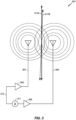
- Figure 1 is an illustration of a single antenna system 101 radiating a signal 103.
- the concentric dotted circles 105 that surround antenna 107 represent peaks of a transmitted waveform.
- a single antenna 107 will generally transmit waveforms as seen in Figure 1 .
- FIG. 2 is an illustration of a two antenna system 201 radiating signals.
- both antennas 207 and 209 are radiating signals of the same frequency.
- they interfere with each other.
- the first type of interference is called destructive interference.
- Destructive interference occurs when a maximum of one signal is at the same point in space and time as the minimum of a second signal. Assuming that signals are of equal strength, the maximum of one signal will cancel out the minimum of the second signal, resulting in no signal.
- Constructive interference occurs when a maximum of one signal is at the same point in space and time as the maximum of a second signal.
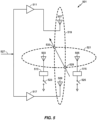
- Points 215a and 215b are at a midpoint 217 between antennas 207 and 209. In the example illustrated in Figure 2 , the midpoint 217 is equally distance between antennas 207 and 209 because antennas 207 and 209 are radiating signals of the same phase in this example.
- the strongest signal from antennas 207 and 209 will lie in zone 219, which for the purposes of this disclosure shall be referenced as the constructive interference zone or beam.
- the constructive interference zone 219 the combined signal from antennas 207 and 209 will be stronger than at any other place equally distance from either antenna 207, 209. Because signal is strongest in the constructive interference zone 219 if a point is in the constructive interference zone, such as point 221 is, it will receive essentially the strongest signal that is the product of constructive interference. For the purposes of this disclosure, we will assume that any points in a constructive interference zone, as drawn, will receive adequate signal to be properly decoded by a receiver such as point 221, which is in the constructive interference zone 219.
- a signal received by a receiver in the constructive interference zone 219 can receive that signal with less overall system transmission power from antennas 207 and 209 than if it were out of that zone. It is therefore desirable from a signal strength standpoint and a transmitted power standpoint that any receiver be in the constructive interference zone 219.
- the constructive interference zone 219 is sometimes referred to as a beam, because it is along that line, or beam, that the highest signal strength signal will be found. It is obviously advantageous to have a receiver in the beam of the transmitter to try to maximize a received signal. It is further advantageous for the transmitter to be able to steer the beam towards a target in order to increase the received signal power by the target.
- FIG 3 is an illustration of a two antenna system 301 radiating signals one of which is phase delayed.
- a signal to be transmitted 313 is coupled to a two antenna system 301.
- the signal to be transmitted 313 is coupled into power amplifier 303 and subsequently into antenna 307.
- the signal 313 is also coupled into a phase shifter 311 and then further coupled into power amplifier 305 and then further coupled into antenna 309.
- both antennas 307 and 309 receive signals of the same magnitude.
- the phase shifter 311 is at 0° the midline of the constructive interference zone (or beam) of the two antennas 307 and 309 is as illustrated at 317a.
- antenna 309 When a phase delay is introduced by the phase shifter 311, antenna 309 will receive a signal that is phase delayed from the signal 313 received by antenna 307. As a consequence of the phase delay, the midline of the beam shifts as shown in 317b. By shifting the phase delay, the center line of the beam can be shifted as shown in 317b, and pointed in a different direction. This allows the beam to be directed or pointed at a receiver or other desired point. This process is commonly known as beam steering.
- FIG 4 is an illustration of a four antenna system 401 such as may be used for 3-dimensional beam steering.
- antennas 403, 405, 407 and 409 are driven by power amplifiers 415, 413, 411, and 417, respectively.
- Each of the power amplifiers 415, 413, 411, and 417 contain phase shifters, which are not explicitly illustrated.
- a signal to be broadcast 410 is coupled into power amplifiers 415, 413, 411, and 417. Zones of constructive interference 419 and 421 result.
- the zones of constructive interference 419 and 421 can be adjusted, and hence can be steered in two dimensions.
- Figure 5 is an illustration of a four antenna system 501, having two driven antennas 507 and 509 and two parasitic antennas 503 and 505, such as may be used for 3-dimensional beam steering.
- Figure 5 also illustrates that not all antennas need be actively driven.
- Driven antennas 507 and 509 are driven by power amplifiers 511 and 517 respectively.
- Parasitic antennas 503 and 505 may be essentially eliminated from the antenna configuration if switches 523 and 525 are open. However if switches 523 and 525 are closed then parasitic antennas 503 and 505 are coupled through tuning networks 513 and 515 to ground. Once switches 523 and 525 are closed, driven antennas 507 and 509 may cause a resonance in parasitic antennas 503 and 505.
- the frequency of this resonance will be the same as frequency of driven antennas 507 and 509, which are driven by the same signal 527.
- the phases of the resonances of parasitic antenna 503 and 505 can be adjusted by tuning networks 513 and 515.
- Tuning networks 513 and 515 may be adjusted by using varying inductances and capacitances. Those variables may be adjusted electronically using components that react to electrical signals, such as switching capacitances and/or inductances in and out of the circuity within tuning networks 513 and 515, or using electrically adjustable components such as varactor diodes. Once switches 523 and 525 are closed, parasitic antennas 503 and 505 will start to resonate at the frequency of signal 527.
- parasitic antennas 503 and 505 Because parasitic antennas 503 and 505 resonate, they will reradiate energy with the phase shift introduced by tuning networks 513 and 515. This will essentially make the antenna system of Figure 5 a two dimensional beam steering system as in Figure 4 .
- a common term for unpowered antennas that resonate with power antennas, then reradiate a portion of that resonance energy at a phase delay determined by a tuning network coupled to the unpowered antennas is "reactive directed array.” The power is reactive because it is a reaction to powered antennas, and the power re-radiated is directed by the tuning network coupled to each of the antennas.
- the antennas 407 403 405 and 409 may be driven with any amount of power that the power amplifiers, 411, 413, 415 and 417 can deliver.
- antennas 407 and 409 can create constructive interference represented by 421, similarly antennas 403 and 405 can create constructive interference represented by 419.
- beam steering in 3-dimensions can be achieved.
- antennas may be used in order to further refine the beam steering capabilities, range capabilities or for other reasons.
- Range extenders commonly rely on adding a beam steering front end that directs the beam for improved channel SNR (Signal to Noise Ratio). Additionally having multiple power amplifiers can provide signal, thereby extending the range beyond that that can be achieved by a single power amplifier and omnidirectional antenna.
- SNR Signal to Noise Ratio
- phase shifters and Power Amplifiers to feed antennas is usually high. Implementation of phase and amplitude control in the RF path is challenging and often implemented with analog phase shifters or complex digital phase shifters, which require high speed, high throughput and high power consumption, at least in a portable device which has limited battery power.
- antenna tuning with reactive elements can be used to take advantage of being able to beam steer with a single powered antenna using reactively coupled directed antenna(s) to create a beam.
- a second antenna may be a powered or reactive antenna or switchable.
- Reactive directive arrays is a known method that uses reactive tuning elements and resonant antennas to provide beam steering and directivity. Using such arrays beam forming can be accomplished using one active PA; along with reactively loaded (parasitic) antennas particularly if the reactive tuning of the resonant antennas is variable. Depending on how the system is used in terms of directivity we would like to be able to configure our antennas and PA accordingly and achieve an acceptable communications link using less power.
- parasitic antennas 503 and 505 can be designed to resonate at the same frequency that driven antennas 507 and 509 broadcast. Additionally parasitic antennas 503 and 505 can adjust the phase that they resonate at with respect to the phase of signals from driven antennas 507 and 509 using tuning networks 513 and 515 when they are activated using switches 523 and 525 respectively. Since antennas are not actively driven by power amplifiers the amount of power that parasitic antennas 503 and 505 can re-radiate is limited by the amount of power they receive from driven antennas 507 and 509. The re-radiated power from antennas 503 and 505however will still affect the beamforming function of the antenna system. By adjusting tuning networks 513 and 515 the direction of the radiated beam (the "radiated beam” or "beam” is a spatial locality where constructive interference increases the signal significantly).
- 521 represents the zone of constructive interference from driven antennas 507 and 509.
- 519 represents the zone of constructive interference from parasitic antennas 503 and 505.
- the space where the zones of constructive interference 521 and 519 constructively interfere with each other, as represented by 533 and 529 are the locations where the beam is at its strongest.
- FIG. 5 is an exemplary system, A practically infinite variation of antenna system arrangements and configurations are possible.
- both driven antennas 507 and 509 were powered antennas driven by power amplifiers 511 and 517. That need not be the case.
- driven antenna 509 could have also been a passive antenna similar to parasitic antennas 503 or 505.
- parasitic antenna 503 For ultimate flexibility all antennas could be switchable between powered and parasitic modes, but obviously a minimum of one must be powered.
- parasitic antennas 503 and 505 can be added to capture and reradiate the energy provided by the powered antennas.
- the drawings depict antennas which are numbered. Instead of each antenna depicted being a single antenna each depiction may represent a group of antennas. For example there is parasitic antenna 503 might a group of parasitic antennas instead of only one. Some individual designs may gain advantages from an array of parasitic antennas some other designs may require only one parasitic antenna. From a practical standpoint one reason parasitic antennas may be added instead of simply adding more driven antennas is that, generally speaking adding driven antennas adds to power consumption and system complexity.
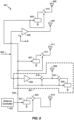
- Figure 6 is an illustration of a five antenna system 601 which will be used, concurrently with Figures 7 , 8 , 9A and 9B to explain some of the aspects of the present disclosure.
- Figure 7 is a graphical representation 701 of areas of constructive interference, as may be produced by different illustrative configurations of the antenna system of Figure 6 to explain some aspects of the present disclosure. They are not intended to be scale, but rather to impart a relative comparative understanding of the different antenna configurations that may be created according to aspects of the present disclosure.
- FIG. 6 a five antenna system 601 is depicted.
- the arrangement illustrated in Figure 6 will be used for purposes of illustration and description, a virtually infinite number of configurations are possible, limited only by practical considerations.
- the five antenna system 601 of Figure 6 can be used in a variety of configurations, for example, to accomplish range extension using beam steering of signal 603.
- Figure 7 represents patterns of maxima of signal strength of the five antenna system 601 of Figure 6 in several configurations. Further assume that any points outside of the gray area are points where the five antenna system 601 cannot reach its intended receiver with an acceptable signal.
- the patterns of maxima are different sizes and shapes to illustrate different aspects of the teachings herein, however they are conceptualizations are not intended to represent actual signal strength charts.
- the five antenna system 601 of Figure 6 will be used to illustrate an antenna system having four separate antenna configurations.
- a first configuration only antenna 607 is driven and no other antenna is active. Since only one antenna is active no beam forming can take place and the points where an acceptable signal can be found form a circular pattern 703 and an acceptable signal can be found in the interior (gray area) of pattern 703.
- Antenna controller 637 may control a variety of devices. For example the antenna controller 637 may control the gain and phase delay in power amplifiers, such as 633 and 635, and switches 615, 617, 619, 621, and 623. In the second configuration, switch 615 is closed by the antenna controller 637 using Control Bus 639. The antenna controller 637 may also select from several tuning parameters in tuning element 625. Tuning element 625 may have variable tuning elements which can be selected by the antenna controller 637. In the second configuration, switch 617 is closed by the antenna controller 637 using control bus 639. The antenna controller 637 may also select from several tuning parameters present in tuning elements 627, 629 and 631.
- the zone where an acceptable communication link can be established is represented as the grey area inside 705 in Figure 7 .
- shape 705 is narrower, illustrating that some of the energy transmitted along the width has been absorbed by parasitic antennas 605 and 607 hence the narrowing of the pattern.
- the pattern of shape 705 however is longer in width as the parasitic antennas 605 and 607 have been tuned to augment the width of the pattern in order to extend the range of the antenna system. If the second configuration cannot establish an acceptable communications link a third configuration may be tried.
- antenna 607 and antenna 609 are driven by power amplifiers 633 and 635 respectively. No other antennas are used in this exemplary mode.
- antennas 609 and 607 are both powered so the range of acceptable performance in increased and is represented in Figure 7 as 707. Having two powered antennas can extend the range considerably, however having two powered amplifiers can consume a considerable amount of energy. If the third configuration is unable provide an acceptable communication link a fourth configuration may be tried.
- both power amplifiers 633 and 635 are on. Additionally switches 615, 617, and 623 couple tuning elements 625, 627, and 631 to antennas 605, 611, and 613 respectively.
- antennas 605, 611 and 613 are tuned for beam forming.
- Consequentially pattern 709 in Figure 7 can represent this fourth antenna configuration.
- the three parasitic antennas 605, 611, and 613 absorb some of the power provided by the powered by powered antennas 607 and 609, narrowing the height of pattern 709 with as the parasitic antennas absorb some of the energy. A portion of the power absorbed by the parasitic 605, 611, and 613 re-radiated.
- the three parasitic antennas 605, 611, and 613, as phase adjusted by tuning elements 625, 627, and 631 respectively, and as such can contribute to beam forming thereby lengthening the width of pattern 709 with respect to the other patterns of Figure 7 .
- Antenna 609 is used in an unusual configuration 641 in that it is configured such that it may be used in 3 different modes.
- antenna 609 is powered by power amplifier 635 by closing switch 619, and opening switch 621.
- both switches 619 and 621 are open, and antenna 609 is essentially invisible to the overall system.
- switch 619 is open and switch 621 is closed thereby coupling antenna 609 to a tuning element 628.
- the antenna 609 can resonate with the powered antenna(s), and re-radiate a portion of that energy phase shifted by an amount determined by tuning element 629.
- FIG 8 is an illustration of an example communication system 801 that may advantageously use various aspects of the teachings herein.
- a broadcast tower is represented at 803.
- Broadcast tower 803 is communicating with mobile unit 805.
- 811 represents the antenna system of mobile unit 805.
- antenna system 811 only shows a single antenna it is representative of an antenna system.
- the antenna system may have several powered antennas. Further the powered antennas may be driven by power amplifiers that allow a phase delay to be inserted. Because phase delays can be inserted between powered antennas the antennas can be actively directed, that is can perform beam steering. Additionally parasite antennas may also be present.
- the parasitic antenna can be coupled into the antenna system by applying a tuning termination, such as 625 or 627.
- the parasitic antenna can be tuned to resonate at the same frequency as the powered antenna. Additionally, by using termination such as 625 or 627 a phase delay can be inserted into the resonance of the parasitic antenna. The resonance will then re-radiate some of its resonance energy at a phase angle (with respect to the powered antenna) which will in turn allow the beam formed by the re-radiation of resonance energy to be directed just as a beam from a powered pair of antenna might.
- the antenna system then comprises two components. A first actively directed array, formed by the driven antennas and phase delays inserted, and a second reactively directed array formed by the parasitic antennas and tuning elements, which allow the reradiated beam from the parasitic antenna to be steered.
- the angle of communication 809 represents the angle between the antenna systems of the mobile unit 805 and broadcast tower 803.
- a communication system tower may provide an attributes message 807.
- a number of pieces of information may be included in the attributes message.
- An attributes message can be useful in deciding whether a communications link is satisfactory. It may contain variables such as received power, signal to noise ratio, quality of service, angle of reception i.e. 809, transmitted power, GPS location of the broadcast tower 803, and a number of other various attributes describing how the broadcast tower 803 is receiving the signal from mobile unit 805 as well as providing information about the broadcast tower 803, such as location transmitted power, etc.
- the attributes can be used, in one aspect, to decide if an acceptable communications link can be established. For example the acceptability of a communication link 813 in the present example illustrated in Figure 8 and described with support from Figures 6 and 7 and others.
- the broadcast tower 803 provides an attributes message to the mobile unit 805.
- the attributes message 807 will contain information about a transmission from the mobile unit 805 as well as data concerning broadcast tower 803.
- the mobile unit 805 can then use information from the attributes message to help the mobile unit 805 establish an extended range which is economical in terms of battery power use.
- the attributes message from the broadcast tower 803 may contain: received power, signal to noise ratio of received power, QOS (Quality Of Service), received angle of transmission, location of the broadcast tower, location of nearby broadcast tower and a host of other information.
- QOS Quality Of Service
- the mobile unit 805 can use the information or a subset of the information provided in the Attributes Message 807 to decide if the communications link 813 between the mobile unit 805 and the broadcast tower 803 is satisfactory or it should change antenna 811 configurations to attempt to achieve an acceptable communications link 813.
- antenna 811 although drawn as a single antenna, represents an antenna system and may actually contain a plurality of physical antennas.
- the mobile sys unit tern 805 may also use the attributes message to attempt to establish an acceptable communications link 813 at reduced power cost, but for the sake of simplicity the emphasis will be on finding an economical (in terms of power consumption) communication link 813 that is satisfactory.
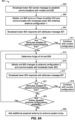
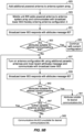
- Figure 9A is a first portion of a flowchart illustrating aspects of an exemplary system employing the teachings herein.
- Figure 9B is a second portion of a flowchart illustrating aspects of an exemplary system employing the teachings herein.
- Figures 9A and 9B taken together, illustrate an embodiment in which a mobile unit 805 is attempting communication with a broadcast tower 803 and is trying to establish a satisfactory communication link 813. It may be useful to think of the example in Figure 8 as a cell phone communicating with a cell tower, however in the description that follows no such assumption is made and the communication system in Figure 8 can represent a variety of systems.
- Figures 9A and 9B are flow charts which describe an exemplary use of many of the teachings herein. Many variations and tweaks of the process described in Figures 9A and 9B are possible so the described process should not be regarded as the only or even the best way of using the disclosed teachings herein, they are designed to be illustrative and not exclusive. The method of Figures 9A and 9B is described illustratively with respect to Figure 6 .
- the exemplary process 901 of seeking an acceptable communications link 813 begins when broadcast tower 803 sends a message to establish communications with mobile unit 805. Control then passes to block 905.
- mobile unit 805 turns on power amplifier 633 and communicates with broadcast tower 803 thus entering the first configuration.
- This is a minimal power setting, with only power amplifier 633 and antenna 707 active.
- the beam is symbolically represented by figure 703 as the power amplifier 633 has just been turned on and, in the present example in antenna configuration, no beam steering control has been implemented as only one antenna is active.
- angle 809 is unknown since the broadcast tower has not received a transmission from mobile unit 805.
- the mobile unit 805 then broadcasts equally in all directions using only antenna 707 to communicate with the broadcast tower 803.
- the antenna system 811 of the mobile unit 805 is in antenna configuration 1 broadcasting with only a single powered antenna 707 and no parasitic antenna(s). Control then passes to block 907.
- broadcast tower 803 responds with an attributes message 807 indicating that the broadcast tower 803 has received the transmission from the mobile unit 805 and knows the antenna system of the mobile unit 805 has entered a new configuration.
- the attributes message 807 may contain a variety of information.
- the attributes message 807 may contain all the information that is necessary for mobile unit 805 to decide whether an acceptable communications link 813 has been attained.
- the mobile unit 805 may use a number of criteria to decide as to whether a satisfactory communications link 813 has been established. The criteria as to whether a satisfactory link has been attained can come from the attributes message, the general communications environment (such as received signal strength, signal to noise ratio of the signal received by the mobile unit or a combination of both. What constitutes a satisfactory communications link 813 is dependent on the use to which it will be put and may vary widely from one application to another.
- the attributes message is examined and a judgment as to whether the communications link 813 is acceptable is made. If the attributes are suitable to create an acceptable communications link 813 then in block 911 the process stops and the current configuration is used. If the communications link 813 is not acceptable then the antenna system 811 can attempt to reconfigure. In the present example control passes to block 913.
- the angle of arrival 809 is determined. This may be done by placing this information in the attributes message 807 that is sent from the broadcast tower 803 to mobile unit 805. It may also be done within the mobile unit 805 by observing a time difference in arrival of a communication link 813 broadcast from the broadcast tower 803 by two separate receiving antennas within the antenna system 811 located within the mobile unit 805. Additionally other methods of finding the angle of arrival 805 (also known as the angle of reception) are known and may be equivalently used. Once the angle of arrival 809 is determined in block 913 control may pass to block 915.
- the second antenna configuration 811 is entered.
- the second configuration only one antenna 607 is powered and parasitic antennas 605 and 611 are coupled, via switches 615 and 617 to tuning elements 625 and 627 respectively.
- Tuning elements 625 and 627 are adjusted so the antenna system beam pattern is elongated via beam steering, illustrated conceptually at 705, to point more power at the broadcast tower 803.
- parasitic antennas 605 and 611 form a reactive directed array, in which antennas 605 and 611 are coupled into the antenna system 811 by achieving a resonance (the reactive part) with antenna 607 and tuning elements 625 and 627 which are tuned (the directed part) to point the antenna system 811 beam towards broadcast tower 803. Control is then transferred to block 917.
- the broadcast tower responds to the antenna configuration change with an updated attributes message 807. Then control is transferred to block 921.
- portions of the attributes message are examined to help determine whether an acceptable communications link 813 has been established. If the communications link is acceptable control is transferred to block 919 and the communications link continues with the current configuration. If the communications link is not acceptable then control is transferred to block 923.
- other parasitic antennas may be added to the antenna system array if there are additional parasitic antennas that have not yet been added.
- antenna 613 can be added to the system at this point if it has not already been added. Accordingly if further parasitic antenna configurations may be added to the antenna system control is transferred to block 913. If no more parasitic antennas are available to add to the antenna array control is transferred to block 925.
- antenna configuration 3 is entered.
- that means using power amplifiers 633 and 635 to drive antennas 607 and 609 respectively. That will increase the areas of effective communication of the communication system 801, as graphically illustrated at 707 in Figure 7 . Since there is now at least a second powered antenna, the signal to the second power amplifier 635 can be phase delayed and the antenna beam aimed at the broadcast tower using its last known position.
- the mobile unit 805 then sends a message to the broadcast tower 803 indicating that antenna system 811 is in configuration 3. Control then passes to block 933.
- block 933 a decision is made as to whether the communications link 813 is acceptable. If the communications link 813 is judged acceptable then block 935 is entered and the communication link 813 is judged as acceptable for use.
- the mobile unit 805 decides that a satisfactory communications link 813 has not been established. If the current communications link 813 is not control is transferred to block 937 where the antenna system is changed to configuration 4 and a message indicating that the antenna system has changed configurations, and is now in configuration 4, is sent to broadcast tower 803. In configuration 4 all antennas 605, 607, 611, 609 and 613 are used. Antennas 607 and 609 are powered, and the remaining parasitic antennas 605, 611, and 613 are tuned using tuning modules 625, 627 and 629. Pattern 709 in Figure 7 represents configuration 4.
- the pattern 709 of constructive interference is narrower; indicating some of the previous power used to power antennas 607 and 609 is being used to resonate the parasitic antennas 605, 611, and 613. Additionally pattern 709 is wider because the zone of constructive interference is augmented by the tuned resonance of the added parasitic antennas which steers the beam towards the broadcast tower 803 target and adds constructive interference. Control is then transferred to 939.
- broadcast tower 803 responds with an attributes message 807 and control is then transferred to block 943.
- the communications link 813 is evaluated to see if satisfactory performance has been achieved... If satisfactory performance has been achieved then control is transferred to block 941 where the current satisfactory antenna configuration is used.
- block 947 it is determined whether further parasitic configurations are available, that is are there further parasitic antenna that can be added to the system? If there are further parasitic antennas that can be added, control is transferred to block 937 to add more parasitic antennas to the antenna system. If, in block 947 there are no further parasitic elements to add to the antenna system 811 then control transfers to block 945 and the communication system has failed to establish a satisfactory communications link.
- the illustrative process 901 has been simplified to enhance understanding.
- the antenna system 811 has f configurations and the process increments through successive configurations until a satisfactory communication link 813 is established or until the process 901 is unable to establish a satisfactory communications link.
- each antenna configuration could have many sub configurations. For example in configuration 1 the setting of power amplifier is likely to have multiple power levels. In such a case it is likely that power amplifier 633 will be started at a low level and the power level increased to a maximum value prior to entering antenna configuration 2. Similarly in antenna configuration 2 the number of parasitic antennas used as reactive directed array elements may be variable as well similarly to the variable amounts of power directed to antenna 607 by power amplifier 633.
- Configuration 3 is similar to configuration 1 except that two power amplifiers 633 and 635 are used the first time configuration 3 is entered.
- the power level of amplifiers 633 and 635 may both be varied.
- Configuration 4 is similar to configuration 2 in that both the power of the amplifiers and the number of parasitic elements comprising a reactive directed array may be varied. If the system is in configuration 4 and all the powered antennas are receiving maximum power and all the parasitic antennas have been included in the antenna system and the antenna system still cannot establish a satisfactory communications link 813 then the system is not suitable for use in the present application.
- Process 901 is illustrative of how the range of a communications link might be extended in steps so as to extend the range in a way economical to the power consumption of the mobile unit 805. Power consumption is an important consideration in portable devices, but even in fixed devices power consumption should be a consideration.
- a software module may reside in RAM memory, flash memory, ROM memory, EPROM memory, EEPROM memory, registers, hard disk, a removable disk, a CD-ROM, or any other form of storage medium known in the art.
- An exemplary storage medium is coupled to the processor such that the processor can read information from, and write information to, the storage medium. In the alternative, the storage medium may be integral to the processor.
- processor can take a variety of forms from an elementary state machine to an internet connection having access to cloud computing resources. What form it takes commonly may depend on the environment and design and implementation requirements.
Landscapes
- Engineering & Computer Science (AREA)
- Computer Networks & Wireless Communication (AREA)
- Signal Processing (AREA)
- Variable-Direction Aerials And Aerial Arrays (AREA)
- Mobile Radio Communication Systems (AREA)
- Radio Transmission System (AREA)
- Compositions Of Oxide Ceramics (AREA)
- Liquid Crystal Substances (AREA)
Claims (15)
- Verfahren (901) zum Steuern einer Antennensystemkonfiguration, um eine zufriedenstellende Kommunikationsverbindung mit einem Ziel bereitzustellen, das Verfahren umfassend:Einschalten (905) einer ersten mit Leistung versorgten Antenne, wodurch in eine erste Antennensystemkonfiguration eingetreten wird;Bestimmen (909), ob die erste Antennensystemkonfiguration die zufriedenstellende Kommunikationsverbindung mit dem Ziel bereitstellen kann; undwenn die erste Antennensystemkonfiguration die zufriedenstellende Kommunikationsverbindung nicht bereitstellen kann, Eintreten (915) in eine zweite Antennensystemkonfiguration, wobei zusätzlich zu der ersten mit Leistung versorgten Antenne mindestens eine weitere Antenne verwendet wird, um einen Abschnitt einer gerichteten Anordnung zu bilden, um einen Antennensystemstrahl in Richtung des Ziels zu lenken, wobei die weitere Antenne auswählbar in einen von einem mit Leistung versorgten Modus, in dem die weitere Antenne als eine zweite mit Leistung versorgte Antenne in der zweiten Antennensystemkonfiguration arbeitet, und einem Resonanzmodus, in dem die weitere Antenne als eine richtungsabgestimmte parasitäre Antenne in der zweiten Antennensystemkonfiguration arbeitet, konfigurierbar ist, wobei die weitere Antenne auch einen inaktiven Modus aufweist, in dem die weitere Antenne von dem Antennensystem in der ersten Antennensystemkonfiguration getrennt ist.
- Verfahren nach Anspruch 1, wobei das Bestimmen, ob die erste Antennensystemkonfiguration die zufriedenstellende Kommunikationsverbindung mit dem Ziel bereitstellen kann, ferner Untersuchen einer Attributnachricht von dem Ziel umfasst; und Entscheiden, zumindest teilweise basierend auf Informationen in der Attributnachricht, ob die Kommunikationsverbindung mit dem Ziel zufriedenstellend ist.
- Verfahren nach Anspruch 2, wobei die mindestens eine weitere Antenne basierend auf der Attributnachricht richtungsabgestimmt wird.
- Verfahren nach Anspruch 1, ferner umfassend, wenn die Kommunikationsverbindung mit dem Ziel in der zweiten Antennensystemkonfiguration nicht zufriedenstellend ist, dann Eintreten in eine dritte Antennensystemkonfiguration, in der mindestens zwei gerichtete mit Leistung versorgte Antennen und keine parasitären Antennen verwendet werden.
- Verfahren nach Anspruch 4, ferner umfassend Entscheiden, ob die dritte Antennensystemkonfiguration eine Kommunikationsverbindung mit dem Ziel produzieren kann, die zufriedenstellend ist.
- Verfahren nach Anspruch 5, wobei Entscheiden, ob die dritte Antennensystemkonfiguration eine Kommunikationsverbindung mit dem Ziel produzieren kann, die zufriedenstellend ist, ferner Entscheiden basierend auf, zumindest teilweise, der Attributnachricht umfasst.
- Verfahren nach Anspruch 4, ferner umfassend Verwenden einer Phasenverzögerung zwischen den mindestens zwei gerichteten mit Leistung versorgten Antennen, um den Antennensystemstrahl in Richtung des Ziels zu lenken.
- Verfahren nach Anspruch 7, wobei die Attributnachricht verwendet wird, um eine Richtung zu bestimmen, die verwendet werden soll, um den Antennensystemstrahl in Richtung des Ziels zu lenken.
- Verfahren nach Anspruch 6, wobei, wenn die dritte Antennensystemkonfiguration keine zufriedenstellende Kommunikationsverbindung produzieren kann, in eine vierte Antennensystemkonfiguration eingetreten wird, wobei mindestens eine abgestimmte parasitäre Antenne hinzugefügt wird.
- Verfahren nach Anspruch 9, wobei das Abstimmen zumindest teilweise von der Attributnachricht abhängt.
- Konfigurierbare Antennenanordnung (601), umfassend:mindestens eine Antenne (607), die mit einem ersten Leistungsverstärker (633) gekoppelt ist; undmindestens eine weitere Antenne (609), wobei die mindestens eine weitere Antenne (609) auswählbar in einen von einem mit Leistung versorgten Modus, in dem die weitere Antenne (609) als eine zweite mit Leistung versorgte Antenne arbeitet, und einem Resonanzmodus, in dem die weitere Antenne (609) als eine richtungsabgestimmte parasitäre Antenne arbeitet, die abgestimmt ist, um einen Teil einer gerichteten Anordnung zu bilden, um einen konfigurierbaren Antennenanordnungsstrahl in Richtung eines Ziels zu lenken, konfigurierbar ist, wobei die weitere Antenne (609) auch einen inaktiven Modus aufweist, in dem die weitere Antenne (609) von der Antennenanordnung (601) getrennt ist.
- Konfigurierbare Antennenanordnung (601) nach Anspruch 11, ferner konfiguriert, um eine Nachricht von dem Ziel anzunehmen und mindestens einen Teil der Nachricht zu verwenden, um einen konfigurierbaren Antennenanordnungsstrahl in Richtung des Ziels zu lenken.
- Konfigurierbare Antennenanordnung (601) nach Anspruch 11, ferner umfassend einen zweiten Leistungsverstärker (635), der ein Signal in Bezug auf den ersten Leistungsverstärker phasenverzögern kann, um den konfigurierbaren Antennenanordnungsstrahl in Richtung des Ziels zu lenken.
- Vorrichtung (601) zum Steuern einer Antennensystemkonfiguration, um eine zufriedenstellende Kommunikationsverbindung (813) mit einem Ziel bereitzustellen, die Vorrichtung (601) umfassend:Mittel (637) zum Einschalten einer ersten mit Leistung versorgten Antenne (607), wodurch in eine erste Antennensystemkonfiguration eingetreten wird;Mittel zum Bestimmen, ob eine zufriedenstellende Kommunikationsverbindung (813) erreicht wurde;Mittel zum Einschalten einer weiteren Antenne (609), wobei die weitere Antenne (609) auswählbar in einen von einem mit Leistung versorgten Modus, in dem die weitere Antenne (609) als eine zweite mit Leistung versorgte Antenne in einer zweiten Antennensystemkonfiguration arbeitet, und einem Resonanzmodus, in dem die weitere Antenne (609) als eine richtungsabgestimmte parasitäre Antenne in der zweiten Antennensystemkonfiguration arbeitet, konfigurierbar ist, wobei die weitere Antenne (609) auch einen inaktiven Modus aufweist, in dem die weitere Antenne (609) von dem Antennensystem in der ersten Antennensystemkonfiguration getrennt ist; undMittel zum Koppeln und Abstimmen von parasitären Antennen, um einen Antennensystemstrahl auf das Ziel zu richten.
- Computerprogramm, umfassend Anweisungen, die, wenn das Programm von einem Computer ausgeführt wird, den Computer veranlassen, das Verfahren nach einem der Ansprüche 1 bis 10 auszuführen.
Applications Claiming Priority (2)
| Application Number | Priority Date | Filing Date | Title |
|---|---|---|---|
| US16/228,715 US11211706B2 (en) | 2018-12-20 | 2018-12-20 | Wireless range extender |
| PCT/US2019/061360 WO2020131257A1 (en) | 2018-12-20 | 2019-11-14 | Wireless range extender |
Publications (3)
| Publication Number | Publication Date |
|---|---|
| EP3900196A1 EP3900196A1 (de) | 2021-10-27 |
| EP3900196C0 EP3900196C0 (de) | 2024-10-09 |
| EP3900196B1 true EP3900196B1 (de) | 2024-10-09 |
Family
ID=68841208
Family Applications (1)
| Application Number | Title | Priority Date | Filing Date |
|---|---|---|---|
| EP19817864.2A Active EP3900196B1 (de) | 2018-12-20 | 2019-11-14 | Erweiterer der drahtlosreichweite |
Country Status (5)
| Country | Link |
|---|---|
| US (1) | US11211706B2 (de) |
| EP (1) | EP3900196B1 (de) |
| CN (1) | CN113169750B (de) |
| TW (1) | TWI772712B (de) |
| WO (1) | WO2020131257A1 (de) |
Family Cites Families (17)
| Publication number | Priority date | Publication date | Assignee | Title |
|---|---|---|---|---|
| US6888504B2 (en) * | 2002-02-01 | 2005-05-03 | Ipr Licensing, Inc. | Aperiodic array antenna |
| US6987493B2 (en) * | 2002-04-15 | 2006-01-17 | Paratek Microwave, Inc. | Electronically steerable passive array antenna |
| US7453413B2 (en) * | 2002-07-29 | 2008-11-18 | Toyon Research Corporation | Reconfigurable parasitic control for antenna arrays and subarrays |
| US7180464B2 (en) | 2004-07-29 | 2007-02-20 | Interdigital Technology Corporation | Multi-mode input impedance matching for smart antennas and associated methods |
| US20060264184A1 (en) * | 2005-02-17 | 2006-11-23 | Interdigital Technology Corporation | Method and apparatus for selecting a beam combination of multiple-input multiple-output antennas |
| EP2117075A4 (de) | 2007-02-28 | 2011-04-20 | Nec Corp | Gruppenantenne, funkkommunikationsvorrichtung und gruppenantennensteuerverfahren |
| US9559756B2 (en) | 2007-08-20 | 2017-01-31 | Ethertronics, Inc. | Antenna system optimized for SISO and MIMO operation |
| US8988289B2 (en) | 2008-03-05 | 2015-03-24 | Ethertronics, Inc. | Antenna system for interference supression |
| US8928541B2 (en) | 2008-03-05 | 2015-01-06 | Ethertronics, Inc. | Active MIMO antenna configuration for maximizing throughput in mobile devices |
| US8378898B2 (en) * | 2008-05-08 | 2013-02-19 | Research In Motion Limited | Mobile wireless communications device with selective antenna load switching and related methods |
| GB2501487A (en) | 2012-04-24 | 2013-10-30 | Renesas Mobile Corp | Multiple frequency antenna involving filter and impedance matching arrangements |
| US20150116162A1 (en) | 2013-10-28 | 2015-04-30 | Skycross, Inc. | Antenna structures and methods thereof for determining a frequency offset based on a differential magnitude |
| US20160204520A1 (en) | 2015-01-08 | 2016-07-14 | Qualcomm Incorporated | Multi-band antenna with a tuned parasitic element |
| KR102284069B1 (ko) * | 2015-01-26 | 2021-07-30 | 한국전자통신연구원 | 스마트 안테나 시스템 및 그 수신 성능 개선방법 |
| US10084321B2 (en) * | 2015-07-02 | 2018-09-25 | Qualcomm Incorporated | Controlling field distribution of a wireless power transmitter |
| US10985462B2 (en) * | 2016-11-30 | 2021-04-20 | Ethertronics, Inc. | Distributed control system for beam steering applications |
| JP2020182138A (ja) * | 2019-04-26 | 2020-11-05 | 株式会社村田製作所 | 高周波回路および通信装置 |
-
2018
- 2018-12-20 US US16/228,715 patent/US11211706B2/en active Active
-
2019
- 2019-11-14 CN CN201980082433.7A patent/CN113169750B/zh active Active
- 2019-11-14 WO PCT/US2019/061360 patent/WO2020131257A1/en not_active Ceased
- 2019-11-14 EP EP19817864.2A patent/EP3900196B1/de active Active
- 2019-11-18 TW TW108141780A patent/TWI772712B/zh active
Also Published As
| Publication number | Publication date |
|---|---|
| EP3900196C0 (de) | 2024-10-09 |
| TWI772712B (zh) | 2022-08-01 |
| WO2020131257A1 (en) | 2020-06-25 |
| US20200203828A1 (en) | 2020-06-25 |
| US11211706B2 (en) | 2021-12-28 |
| EP3900196A1 (de) | 2021-10-27 |
| TW202029666A (zh) | 2020-08-01 |
| CN113169750B (zh) | 2023-01-10 |
| CN113169750A (zh) | 2021-07-23 |
Similar Documents
| Publication | Publication Date | Title |
|---|---|---|
| US9123986B2 (en) | Antenna system for interference supression | |
| US11239572B2 (en) | Beam-steering reconfigurable antenna arrays | |
| US6314305B1 (en) | Transmitter/receiver for combined adaptive array processing and fixed beam switching | |
| US9571176B2 (en) | Active MIMO antenna configuration for maximizing throughput in mobile devices | |
| US8604988B2 (en) | Multi-function array for access point and mobile wireless systems | |
| US9160074B2 (en) | Modal antenna with correlation management for diversity applications | |
| US6894653B2 (en) | Low cost multiple pattern antenna for use with multiple receiver systems | |
| US20050179607A1 (en) | Method and apparatus for dynamically selecting the best antennas/mode ports for transmission and reception | |
| JP3211445U (ja) | ダイバーシティ用途のための相関調整を有するモーダルアンテナ | |
| US20070210974A1 (en) | Low cost multiple pattern antenna for use with multiple receiver systems | |
| US8928541B2 (en) | Active MIMO antenna configuration for maximizing throughput in mobile devices | |
| US20200399055A1 (en) | Repeater with Multimode Antenna | |
| EP3900196B1 (de) | Erweiterer der drahtlosreichweite | |
| WO2018102326A1 (en) | Super directive array of volumetric antenna elements for wireless device applications | |
| WO2008136003A2 (en) | Method and devices for phased array beam scanning |
Legal Events
| Date | Code | Title | Description |
|---|---|---|---|
| STAA | Information on the status of an ep patent application or granted ep patent |
Free format text: STATUS: UNKNOWN |
|
| STAA | Information on the status of an ep patent application or granted ep patent |
Free format text: STATUS: THE INTERNATIONAL PUBLICATION HAS BEEN MADE |
|
| PUAI | Public reference made under article 153(3) epc to a published international application that has entered the european phase |
Free format text: ORIGINAL CODE: 0009012 |
|
| STAA | Information on the status of an ep patent application or granted ep patent |
Free format text: STATUS: REQUEST FOR EXAMINATION WAS MADE |
|
| 17P | Request for examination filed |
Effective date: 20210602 |
|
| AK | Designated contracting states |
Kind code of ref document: A1 Designated state(s): AL AT BE BG CH CY CZ DE DK EE ES FI FR GB GR HR HU IE IS IT LI LT LU LV MC MK MT NL NO PL PT RO RS SE SI SK SM TR |
|
| DAV | Request for validation of the european patent (deleted) | ||
| DAX | Request for extension of the european patent (deleted) | ||
| GRAP | Despatch of communication of intention to grant a patent |
Free format text: ORIGINAL CODE: EPIDOSNIGR1 |
|
| STAA | Information on the status of an ep patent application or granted ep patent |
Free format text: STATUS: GRANT OF PATENT IS INTENDED |
|
| RIC1 | Information provided on ipc code assigned before grant |
Ipc: H01Q 3/24 20060101ALN20240430BHEP Ipc: H01Q 3/26 20060101ALI20240430BHEP Ipc: H04B 1/04 20060101AFI20240430BHEP |
|
| INTG | Intention to grant announced |
Effective date: 20240524 |
|
| RIC1 | Information provided on ipc code assigned before grant |
Ipc: H01Q 3/24 20060101ALN20240513BHEP Ipc: H01Q 3/26 20060101ALI20240513BHEP Ipc: H04B 1/04 20060101AFI20240513BHEP |
|
| GRAS | Grant fee paid |
Free format text: ORIGINAL CODE: EPIDOSNIGR3 |
|
| GRAA | (expected) grant |
Free format text: ORIGINAL CODE: 0009210 |
|
| STAA | Information on the status of an ep patent application or granted ep patent |
Free format text: STATUS: THE PATENT HAS BEEN GRANTED |
|
| AK | Designated contracting states |
Kind code of ref document: B1 Designated state(s): AL AT BE BG CH CY CZ DE DK EE ES FI FR GB GR HR HU IE IS IT LI LT LU LV MC MK MT NL NO PL PT RO RS SE SI SK SM TR |
|
| REG | Reference to a national code |
Ref country code: CH Ref legal event code: EP |
|
| REG | Reference to a national code |
Ref country code: DE Ref legal event code: R096 Ref document number: 602019060181 Country of ref document: DE |
|
| REG | Reference to a national code |
Ref country code: IE Ref legal event code: FG4D |
|
| U01 | Request for unitary effect filed |
Effective date: 20241023 |
|
| U07 | Unitary effect registered |
Designated state(s): AT BE BG DE DK EE FI FR IT LT LU LV MT NL PT RO SE SI Effective date: 20241106 |
|
| U20 | Renewal fee for the european patent with unitary effect paid |
Year of fee payment: 6 Effective date: 20250128 |
|
| PG25 | Lapsed in a contracting state [announced via postgrant information from national office to epo] |
Ref country code: IS Free format text: LAPSE BECAUSE OF FAILURE TO SUBMIT A TRANSLATION OF THE DESCRIPTION OR TO PAY THE FEE WITHIN THE PRESCRIBED TIME-LIMIT Effective date: 20250209 Ref country code: HR Free format text: LAPSE BECAUSE OF FAILURE TO SUBMIT A TRANSLATION OF THE DESCRIPTION OR TO PAY THE FEE WITHIN THE PRESCRIBED TIME-LIMIT Effective date: 20241009 |
|
| PG25 | Lapsed in a contracting state [announced via postgrant information from national office to epo] |
Ref country code: ES Free format text: LAPSE BECAUSE OF FAILURE TO SUBMIT A TRANSLATION OF THE DESCRIPTION OR TO PAY THE FEE WITHIN THE PRESCRIBED TIME-LIMIT Effective date: 20241009 |
|
| PG25 | Lapsed in a contracting state [announced via postgrant information from national office to epo] |
Ref country code: NO Free format text: LAPSE BECAUSE OF FAILURE TO SUBMIT A TRANSLATION OF THE DESCRIPTION OR TO PAY THE FEE WITHIN THE PRESCRIBED TIME-LIMIT Effective date: 20250109 |
|
| PG25 | Lapsed in a contracting state [announced via postgrant information from national office to epo] |
Ref country code: GR Free format text: LAPSE BECAUSE OF FAILURE TO SUBMIT A TRANSLATION OF THE DESCRIPTION OR TO PAY THE FEE WITHIN THE PRESCRIBED TIME-LIMIT Effective date: 20250110 |
|
| PG25 | Lapsed in a contracting state [announced via postgrant information from national office to epo] |
Ref country code: PL Free format text: LAPSE BECAUSE OF FAILURE TO SUBMIT A TRANSLATION OF THE DESCRIPTION OR TO PAY THE FEE WITHIN THE PRESCRIBED TIME-LIMIT Effective date: 20241009 |
|
| PG25 | Lapsed in a contracting state [announced via postgrant information from national office to epo] |
Ref country code: RS Free format text: LAPSE BECAUSE OF FAILURE TO SUBMIT A TRANSLATION OF THE DESCRIPTION OR TO PAY THE FEE WITHIN THE PRESCRIBED TIME-LIMIT Effective date: 20250109 |
|
| REG | Reference to a national code |
Ref country code: CH Ref legal event code: PL |
|
| PG25 | Lapsed in a contracting state [announced via postgrant information from national office to epo] |
Ref country code: SM Free format text: LAPSE BECAUSE OF FAILURE TO SUBMIT A TRANSLATION OF THE DESCRIPTION OR TO PAY THE FEE WITHIN THE PRESCRIBED TIME-LIMIT Effective date: 20241009 |
|
| PG25 | Lapsed in a contracting state [announced via postgrant information from national office to epo] |
Ref country code: MC Free format text: LAPSE BECAUSE OF FAILURE TO SUBMIT A TRANSLATION OF THE DESCRIPTION OR TO PAY THE FEE WITHIN THE PRESCRIBED TIME-LIMIT Effective date: 20241009 |
|
| REG | Reference to a national code |
Ref country code: CH Ref legal event code: PL |
|
| PG25 | Lapsed in a contracting state [announced via postgrant information from national office to epo] |
Ref country code: CH Free format text: LAPSE BECAUSE OF NON-PAYMENT OF DUE FEES Effective date: 20241130 |
|
| PG25 | Lapsed in a contracting state [announced via postgrant information from national office to epo] |
Ref country code: SK Free format text: LAPSE BECAUSE OF FAILURE TO SUBMIT A TRANSLATION OF THE DESCRIPTION OR TO PAY THE FEE WITHIN THE PRESCRIBED TIME-LIMIT Effective date: 20241009 |
|
| PG25 | Lapsed in a contracting state [announced via postgrant information from national office to epo] |
Ref country code: CZ Free format text: LAPSE BECAUSE OF FAILURE TO SUBMIT A TRANSLATION OF THE DESCRIPTION OR TO PAY THE FEE WITHIN THE PRESCRIBED TIME-LIMIT Effective date: 20241009 |
|
| PLBE | No opposition filed within time limit |
Free format text: ORIGINAL CODE: 0009261 |
|
| STAA | Information on the status of an ep patent application or granted ep patent |
Free format text: STATUS: NO OPPOSITION FILED WITHIN TIME LIMIT |
|
| 26N | No opposition filed |
Effective date: 20250710 |
|
| U20 | Renewal fee for the european patent with unitary effect paid |
Year of fee payment: 7 Effective date: 20251014 |
|
| PGFP | Annual fee paid to national office [announced via postgrant information from national office to epo] |
Ref country code: GB Payment date: 20251009 Year of fee payment: 7 |
|
| PGFP | Annual fee paid to national office [announced via postgrant information from national office to epo] |
Ref country code: IE Payment date: 20251013 Year of fee payment: 7 |
|
| PG25 | Lapsed in a contracting state [announced via postgrant information from national office to epo] |
Ref country code: HU Free format text: LAPSE BECAUSE OF FAILURE TO SUBMIT A TRANSLATION OF THE DESCRIPTION OR TO PAY THE FEE WITHIN THE PRESCRIBED TIME-LIMIT; INVALID AB INITIO Effective date: 20191114 |