EP3899574B1 - Mehrbereichs-festkörperlidarsystem - Google Patents
Mehrbereichs-festkörperlidarsystem Download PDFInfo
- Publication number
- EP3899574B1 EP3899574B1 EP19839611.1A EP19839611A EP3899574B1 EP 3899574 B1 EP3899574 B1 EP 3899574B1 EP 19839611 A EP19839611 A EP 19839611A EP 3899574 B1 EP3899574 B1 EP 3899574B1
- Authority
- EP
- European Patent Office
- Prior art keywords
- light
- light source
- photodetector
- view
- field
- Prior art date
- Legal status (The legal status is an assumption and is not a legal conclusion. Google has not performed a legal analysis and makes no representation as to the accuracy of the status listed.)
- Active
Links
Images




Classifications
-
- G—PHYSICS
- G01—MEASURING; TESTING
- G01S—RADIO DIRECTION-FINDING; RADIO NAVIGATION; DETERMINING DISTANCE OR VELOCITY BY USE OF RADIO WAVES; LOCATING OR PRESENCE-DETECTING BY USE OF THE REFLECTION OR RERADIATION OF RADIO WAVES; ANALOGOUS ARRANGEMENTS USING OTHER WAVES
- G01S17/00—Systems using the reflection or reradiation of electromagnetic waves other than radio waves, e.g. lidar systems
- G01S17/02—Systems using the reflection of electromagnetic waves other than radio waves
- G01S17/04—Systems determining the presence of a target
-
- G—PHYSICS
- G01—MEASURING; TESTING
- G01S—RADIO DIRECTION-FINDING; RADIO NAVIGATION; DETERMINING DISTANCE OR VELOCITY BY USE OF RADIO WAVES; LOCATING OR PRESENCE-DETECTING BY USE OF THE REFLECTION OR RERADIATION OF RADIO WAVES; ANALOGOUS ARRANGEMENTS USING OTHER WAVES
- G01S17/00—Systems using the reflection or reradiation of electromagnetic waves other than radio waves, e.g. lidar systems
- G01S17/87—Combinations of systems using electromagnetic waves other than radio waves
-
- G—PHYSICS
- G01—MEASURING; TESTING
- G01S—RADIO DIRECTION-FINDING; RADIO NAVIGATION; DETERMINING DISTANCE OR VELOCITY BY USE OF RADIO WAVES; LOCATING OR PRESENCE-DETECTING BY USE OF THE REFLECTION OR RERADIATION OF RADIO WAVES; ANALOGOUS ARRANGEMENTS USING OTHER WAVES
- G01S17/00—Systems using the reflection or reradiation of electromagnetic waves other than radio waves, e.g. lidar systems
- G01S17/88—Lidar systems specially adapted for specific applications
- G01S17/89—Lidar systems specially adapted for specific applications for mapping or imaging
-
- G—PHYSICS
- G01—MEASURING; TESTING
- G01S—RADIO DIRECTION-FINDING; RADIO NAVIGATION; DETERMINING DISTANCE OR VELOCITY BY USE OF RADIO WAVES; LOCATING OR PRESENCE-DETECTING BY USE OF THE REFLECTION OR RERADIATION OF RADIO WAVES; ANALOGOUS ARRANGEMENTS USING OTHER WAVES
- G01S17/00—Systems using the reflection or reradiation of electromagnetic waves other than radio waves, e.g. lidar systems
- G01S17/88—Lidar systems specially adapted for specific applications
- G01S17/93—Lidar systems specially adapted for specific applications for anti-collision purposes
- G01S17/931—Lidar systems specially adapted for specific applications for anti-collision purposes of land vehicles
-
- G—PHYSICS
- G01—MEASURING; TESTING
- G01S—RADIO DIRECTION-FINDING; RADIO NAVIGATION; DETERMINING DISTANCE OR VELOCITY BY USE OF RADIO WAVES; LOCATING OR PRESENCE-DETECTING BY USE OF THE REFLECTION OR RERADIATION OF RADIO WAVES; ANALOGOUS ARRANGEMENTS USING OTHER WAVES
- G01S7/00—Details of systems according to groups G01S13/00, G01S15/00, G01S17/00
- G01S7/48—Details of systems according to groups G01S13/00, G01S15/00, G01S17/00 of systems according to group G01S17/00
- G01S7/481—Constructional features, e.g. arrangements of optical elements
- G01S7/4811—Constructional features, e.g. arrangements of optical elements common to transmitter and receiver
-
- G—PHYSICS
- G01—MEASURING; TESTING
- G01S—RADIO DIRECTION-FINDING; RADIO NAVIGATION; DETERMINING DISTANCE OR VELOCITY BY USE OF RADIO WAVES; LOCATING OR PRESENCE-DETECTING BY USE OF THE REFLECTION OR RERADIATION OF RADIO WAVES; ANALOGOUS ARRANGEMENTS USING OTHER WAVES
- G01S7/00—Details of systems according to groups G01S13/00, G01S15/00, G01S17/00
- G01S7/48—Details of systems according to groups G01S13/00, G01S15/00, G01S17/00 of systems according to group G01S17/00
- G01S7/481—Constructional features, e.g. arrangements of optical elements
- G01S7/4811—Constructional features, e.g. arrangements of optical elements common to transmitter and receiver
- G01S7/4813—Housing arrangements
-
- G—PHYSICS
- G01—MEASURING; TESTING
- G01S—RADIO DIRECTION-FINDING; RADIO NAVIGATION; DETERMINING DISTANCE OR VELOCITY BY USE OF RADIO WAVES; LOCATING OR PRESENCE-DETECTING BY USE OF THE REFLECTION OR RERADIATION OF RADIO WAVES; ANALOGOUS ARRANGEMENTS USING OTHER WAVES
- G01S7/00—Details of systems according to groups G01S13/00, G01S15/00, G01S17/00
- G01S7/48—Details of systems according to groups G01S13/00, G01S15/00, G01S17/00 of systems according to group G01S17/00
- G01S7/481—Constructional features, e.g. arrangements of optical elements
- G01S7/4814—Constructional features, e.g. arrangements of optical elements of transmitters alone
- G01S7/4815—Constructional features, e.g. arrangements of optical elements of transmitters alone using multiple transmitters
Definitions
- a solid-state Lidar system includes a photodetector or an array of photodetectors that is essentially fixed in place relative to a carrier, e.g., a vehicle.
- Light is emitted into the field of view of the photodetector and the photodetector detects light that is reflected by an object in the field of view.
- a Flash Lidar system emits pulses of light, e.g., laser light, into the field of view.
- the detection of reflected light is used to generate a 3D environmental map of the surrounding environment.
- the time of flight of the reflected photon detected by the photodetector is used to determine the distance of the object that reflected the light.
- the solid-state Lidar system may be mounted to a vehicle to detect objects in the environment surrounding the vehicle and to detect distance of those objects for environmental mapping.
- the output of the solid-state Lidar system may be used, for example, to autonomously or semi-autonomously control operation of the vehicle, e.g., propulsion, braking, steering, etc.
- the system may be a component of or in communication with an advanced driver-assistance system (ADAS) of the vehicle.
- ADAS advanced driver-assistance system
- the system 10 is a light detection and ranging (Lidar) system.
- the system 10 includes two fields of view FV1, FV2 and emits light into the fields of view FV1, FV2.
- the system 10 detects the emitted light that is reflected by objects in the fields of view FV1, FV2, e.g., pedestrians, street signs, vehicle 12, etc.
- the system 10 separately collects the reflected light from the two fields of view FV1, FV2.
- the system 10 is shown in Figure 1 as being mounted to a vehicle 12.
- the system 10 is operated to detect objects in the environment surrounding the vehicle 12 and to detect distance of those objects for environmental mapping.
- the output of the system 10 may be used, for example, to autonomously or semi-autonomously control operation of the vehicle 12, e.g., propulsion, braking, steering, etc.
- the system 10 may be a component of or in communication with an advanced driver-assistance system (ADAS) of the vehicle 12.
- ADAS advanced driver-assistance system
- the system 10 may be mounted to the vehicle 12 in any suitable position (as one example, the system 10 is shown on the front of the vehicle 12 and directed forward).
- the vehicle 12 may have more than one system 10 and/or the vehicle 12 may include other object detection system 10, including other Lidar systems.
- the vehicle 12 is shown in Figure 1 as including a single system 10 aimed in a forward direction merely as an example.
- the vehicle 12 shown in the Figures is a passenger automobile.
- the vehicle 12 may be of any suitable manned or un-manned type including a plane, satellite, drone, watercraft, etc.
- the system 10 may be a solid-state Lidar system.
- the system 10 is stationary relative to the vehicle 12.
- the system 10 may include a casing 14 that is fixed relative to the vehicle 12 and a silicon substrate of the system 10 is fixed to the casing 14.
- the system 10 may be a staring, non-moving system.
- the system 10 may include elements to adjust the aim of the system 10, e.g., the direction of the emitted light may be controlled by, for example, optics, mirrors, etc.
- the system 10 may be a Flash Lidar system.
- the system 10 emits pulses of light into the fields of view FV1, FV2.
- the system 10 may be a 3D Flash Lidar system 10 that generates a 3D environmental map of the surrounding environment, as shown in part in Figure 1 .
- An example of a compilation of the data into a 3D environmental map is shown in the fields of view FV1, FV2 in Figure 1 .
- the system 10 includes a system controller 16 and two pairs of light sources 18, 22 and photodetectors 20, 24. Specifically, one pair includes a first light source 18 and a first photodetector 20, and the other pair includes a second light source 22 and a second photodetector 24. As described further below, the first light source 18 emits light into the first field of view of the first photodetector 20, i.e., the first field of view FV1, and the second light source 22 emits light into the field of view of the second photodetector 24, i.e., the second field of view FV2.
- the system 10 may also include a third pair having a third light source 26 and a third photodetector 28, in which case the third light source 26 emits light into the field of view of the third photodetector 28, i.e., the third field of view FV3.
- the system 10 may include two or more pairs of light sources and photodetectors.
- the system 10 may be a unit.
- the first light source 18, first photodetector 20, second light source 22, second photodetector 24, and the system controller 16 may be supported by a common substrate that is attached to the vehicle 12, e.g., a casing 14 as schematically shown in Figures 2-5 .
- the third light source 26 and the third photodetector 28 are supported by the casing 14.
- the casing 14 may, for example, enclose the other components of the system 10 and may include mechanical attachment features to attach the casing 14 to the vehicle 12 and electronic connections to connect to and communicate with electronic system 10 of the vehicle 12, e.g., components of the ADAS.
- the casing 14, may be plastic or metal and may protect the other components of the system 10 from environmental precipitation, dust, etc.
- the system 10 may include multiple casings with each casing containing components of the system 10.
- one casing may including one or more of the pairs of light sources 18, 22, 26 and photodetectors 20, 24, 28 and another casing may include one or more of the pairs of light sources 18, 22, 26 and photodetectors 20, 24, 28.
- one or more of the pairs of light sources 18, 22, 26 and photodetectors 20, 24, 28 may be split among separate casings.
- the system 10 may include any suitable number of casings.
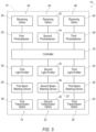
- the controller 16 may be a microprocessor-based controller or field programmable gate array (FPGA) implemented via circuits, chips, and/or other electronic components.
- the controller 16 is a physical, i.e., structural, component of the system 10.
- the controller 16 may include a processor, memory, etc.
- the memory of the controller 16 may store instructions executable by the processor, i.e., processor-executable instructions, and/or may store data.
- the controller 16 may be in communication with a communication network of the vehicle 12 to send and/or receive instructions from the vehicle 12, e.g., components of the ADAS.
- the controller 16 communicates with the light sources 18, 22, 26 and the photodetectors 20, 24, 28. Specifically, the controller 16 instructs the first light source 18 to emit light and substantially simultaneously initiates a clock. When the light is reflected, i.e., by an object in the first field of view FV1, the first photodetector 20 detects the reflected light and communicates this detection to the controller 16, which the controller 16 uses to identify object location and distance to the object (based time of flight of the detected photon using the clock initiated at the emission of light from the first light source 18).
- the controller 16 uses these outputs from the first photodetector 20 to create the environmental map and/or communicates the outputs from the first photodetector 20 to the vehicle 12, e.g., components of the ADAS, to create the environmental map. Specifically, the controller 16 continuously repeats the light emission and detection of reflected light for building and updating the environmental map. While the first light source 18 and first photodetector 20 were used as examples, the controller 16 similarly communicates with second light source 22 and second photodetector 24 and with the third light source 26 and the third photodetector 28.
- the light sources 18, 22, 26 emit light into the fields of view FV1, FV2, FV3, respectively, for detection by the respective photodetector when the light is reflected by an object in the respective field of view FV1, FV2, FV3.
- the light sources 18, 22, 26 may have similar or identical architecture and/or design.
- the light sources 18, 22, 26 may include the same type of components arranged in the same manner, in which case the corresponding components of the light sources 18, 22, 26 may be identical or may have varying characteristics (e.g., for emission of different light wavelengths as described below).
- the light sources 18, 22, 26 may each include a light emitter (i.e., a first light emitter 30, a second light emitter 32, a third light emitter 34).
- the light emitter 30, 32, 34 may be a laser.
- the light emitter 30, 32, 34 may be, for example, a semiconductor laser.
- the light emitter 30, 32, 34 is a vertical-cavity surface-emitting laser (VCSEL).
- the light emitter 30, 32, 34 may be a diode-pumped solid-state laser (DPSSL).
- the light emitter 30, 32, 34 may be an edge emitting laser diode.
- the light sources 18, 22, 26 may be designed to emit a pulsed flash of light, e.g., a pulsed laser light.
- the light emitter 30, 32, 34 e.g., the VCSEL, is designed to emit a pulsed laser light.
- the light emitted by the light emitters 30, 32, 34 may be, for example, infrared light.
- the light emitted by the light emitters 30, 32, 34 may be of any suitable wavelength, as also described further below.
- the system 10 may be a staring, non-moving system.
- the system 10 may include elements to adjust the aim of the system 10.
- any of the light sources 18, 22, 26 may include beam steering device 36 that direct and/or diffuse the light from the light emitter 30, 32, 34 into the respective field of view FV1, FV2, FV3.
- the light beams are emitted from the system 10 as horizontal lines.
- the beam steering device 36 may emit the light as the horizontal beam and/or may adjust the vertical location of the light beam.
- the beam steering devices 36 are shown in Figures 2-5 , it should be appreciated that the beam steering devices 36 may be eliminated from Figures 2-5 in an example where the system 10 is a staring, non-moving system.
- the light source 18, 22, 26, e.g., the VCSEL exposes the entire respective field of view FV1, FV2, FV3 at once, i.e., at the same time.
- the beam steering device 36 may be a micromirror.
- the beam steering device 36 may be a micro-electro-mechanical system 10 (MEMS) mirror.
- the beam steering device 36 may be a digital micromirror device (DMD) that includes an array of pixel-mirrors that are capable of being tilted to deflect light.
- the MEMS mirror may include a mirror on a gimbal that is tilted, e.g., by application of voltage.
- the beam steering device 36 may be a liquid-crystal solid-state device.
- first, second, and third beam steering devices are all labeled with reference numeral 36, it should be appreciated that the beam steering devices 36 may of the same type or different types; and in examples in which the beam steering devices 36 are of the same type, the beam steering devices 36 may be identical or may have different characteristics.
- the system 10 includes transmission optics through which light exits the system 10.
- the first light source 18 includes first transmission optics 38 through which light emitted by the first light emitter 30 exits the system 10 into the first field of view FV1 and second transmission optics 40 through which light emitted by the second light emitter 32 exits the system 10 into the second field of view FV2.
- the third light source 26 includes third transmission optics 42 through which light emitted by the third light emitter 34 exits the system 10 into the third field of view FV3.
- the transmission optics 38, 40, 42 may include any suitable number of lenses.
- the transmission optics 38, 40, 42 may have similar or identical architecture and/or design.
- the transmission optics 38, 40, 42 may include the same type of components arranged in the same manner, in which case the corresponding components of the transmission optics 38, 40, 42 may be identical or may have varying characteristics (e.g., for emission of different light wavelengths as described below).
- the first light source 18 is aimed at the first field of view FV1 and the second light source 22 is aimed at the second field of view FV2.
- the system 10 emits light from the first light source 18 into a first field of illumination and emits light from the second light source 22 into a second field of illumination.
- the third light source 26 is aimed at the third field of view FV3.
- the field of illumination is the area exposed to light emitted from the light sources 18, 22, 26.
- the first field of illumination may substantially match the first field of view FV1 and the second field of illumination may substantially match the second field of view FV2 ("substantially match” is based on manufacturing capabilities and tolerances of the light sources 18, 22, 26 and the photodetectors 20, 24, 28), as is the case shown for example in Figure 1 .
- the first field of illumination and the second field of illumination may overlap, as described further below.
- the second field of illumination and the third field of illumination may overlap, as described further below.
- the system 10 includes a first receiving unit 44 and a second receiving unit 46.
- the system 10 may include a third receiving unit 48.
- the first receiving unit 44 includes the first photodetector 20 and may include first receiving optics 50.
- the second receiving unit 46 includes the second photodetector 24 and may include second receiving optics 52.
- the third receiving unit 48 includes the third photodetector 28 and may include third receiving optics 54.
- the term "photodetector” includes a single photodetector or an array of photodetectors, e.g., an array of photodiodes.
- the photodetectors 20, 24, 28 may be, for example, avalanche photodiode detectors.
- the photodetectors 20, 24, 28 may be a single-photon avalanche diode (SPAD).
- the photodetectors 20, 24, 28 may be a PIN diode.
- the photodetectors 20, 24, 28 may have similar or identical architecture and/or design.
- the photodetectors 20, 24, 28 may include the same type of components arranged in the same manner, in which case the corresponding components of the photodetectors 20, 24, 28 may be identical or may have varying characteristics.
- the first field of view FV1 is the area in which reflected light may be sensed by the first photodetector 20
- the second field of view FV2 is the area in which reflected light may be sensed by the second photodetector 24
- the third field of view FV3 is the area in which reflected light may be sensed by the third photodetector 28.
- the first field of view FV1 and the second field of view FV2 may overlap. In other words, as least part of the first field of view FV1 and at least part of the second field of view FV2 occupy the same space such that an object in the overlap will reflect light toward both photodetectors 20, 24.
- the first field of view FV1 and the second field of view FV2 may be centered on each other, i.e., aimed in substantially the same direction ("substantially the same” is based on manufacturing capabilities and tolerances of the light sources 18, 22, 26 and the photodetectors 20, 24, 28).
- the first field of view FV1 and the second field of view FV2 may be aimed in different directions while overlapping.
- the second field of view FV2 and third field of view FV3 may overlap.
- the second field of view FV2 and the third field of view FV3 may be aimed in different directions while overlapping.
- the first field of view FV1, the second field of view FV2, and the third field of view FV3 are each aimed in a different direction.
- the fields of view FV1, FV2, FV3 may have different widths and/or lengths.
- the length of the first field of view FV1 is shorter than the length of the second field of view FV2.
- the first photodetector 20 has a short range and the second photodetector 24 has a long range.
- the first field of view FV1 is wider than the second field of view FV2.
- the receiving optics 50, 52, 54 may include any suitable number of lenses, filters, etc.
- the system 10 may distinguish between the reflected light that was emitted by the first light source 18 and reflected light that was emitted by the second light source 22 based on differences in wavelength of the light.
- the first light source 18 and the second light source 22 may emit light having different wavelengths ⁇ 1, ⁇ 2 and the first receiving unit 44 and the second receiving unit 46 may detect light having different wavelengths ⁇ 1, ⁇ 2.
- the first receiving unit 44 may be designed to detect the wavelength ⁇ 1 of light that was emitted from the first light source 18 and reflected by a reflecting surface in the first field of view FV1 (and detect little or no light at wavelength ⁇ 2 emitted from the second light source 22) and the second receiving unit 46 may be designed to detect wavelength ⁇ 2 of the light that was emitted from the second light source 22 and reflected by a reflecting surface in the second field of view FV2 (and detect little or no light at wavelength ⁇ 1 emitted from the first light source 18).
- the third receiving unit 48 may be designed to detect light that was emitted from the third light source 26 at a third wavelength ⁇ 3 and reflected by a reflecting surface in the third field of view FV3 (and detect little or no light emitted at wavelengths ⁇ 1, ⁇ 2 from the first light source 18 and the second light source 22).
- the third receiving unit 48 may be designed to detect light that was emitted from the third light source 26 at the first wavelength ⁇ 1 and reflected by a reflecting surface in the third field of view FV3.
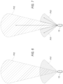
- the first receiving unit 44 and the third receiving unit 48 are pointed in different directions such that the first and third fields of view FV1, FV3 do not overlap (see Fig. 7 ).
- Figure 6 is a schematic showing the operation of the example shown in Figure 2
- Figure 7 is a schematic showing the operation of the example, shown in Figure 3 .
- the first light source 18 is designed to emit light having a first wavelength ⁇ 1 (see Fig. 8 )
- the second light source 22 is designed to emit light having a second wavelength ⁇ 2 (see Fig. 8 ).
- First wavelength ⁇ 1 and second wavelength ⁇ 2 are different.
- the first receiving unit 44 transmits light at the first wavelength ⁇ 1, i.e., light reflected in the first field of view FV1, and filters out light at the second wavelength ⁇ 2 and the second receiving unit 46 transmits light at the second wavelength ⁇ 2, i.e., light reflected in the second field of view FV2, and filters out light at the first wavelength ⁇ 1.
- the system is able to distinguish between reflections in the first and second fields of view FV1, FV2.
- the first light source 18, the second light source 22, the third light source 26 may be designed to emit light at the desired wavelength.
- the first light emitter 30, the second light emitter 32, and the third light emitter 34 may be designed to generate and emit light at the desired wavelength.
- the transmitting optics may include bandpass filters that filter the light emitted from the light emitters 30, 32, 34 to the desired wavelength.
- the first receiving optics 50 may include a first bandpass filter 56 and the second receiving optics 52 may include a second bandpass filter 58.
- the third receiving optics 54 may include a third bandpass filter 60.
- the bandpass filters 56, 58, 60 are optical filters, i.e., physical elements that are at least part of the receiving optics 50, 52, 54.
- the first bandpass filter 56 covers the first photodetector 20 and the second bandpass filter 58 covers the second photodetector 24, i.e., reflected light entering the system 10 travels through at least one of the bandpass filters.
- the third bandpass filter 60 covers the third photodetector 28.
- the bandpass filters 56, 58, 60 may be narrow-bandpass filters.
- Figure 8 shows operation of the bandpass filters 56, 58.
- Figure 8 shows the wavelength curves of the light emitted from the first light source 18 and the second light source 22 shown in solid lines.
- the dotted lines show the wavelength curve of the first bandpass filter 56 having a first bandwidth BW1 and the second bandpass filter having a second bandwidth BW2.
- the first bandpass filter 56 is designed to transmit light in the first bandwidth BW1 (and attenuate outside the first bandwidth BW1) and the second bandpass filter 58 designed to transmit light in a second bandwidth BW2 (and attenuate outside the second bandwidth BW2).
- the wavelength range of light emitted from the first light source 18 is in the first bandwidth BW1 and the wavelength range of light emitted from the second light source 22 is in the second bandwidth BW2.
- the first light source 18 is designed to emit light in the first bandwidth BW1 and the second light source 22 is designed to emit light in the second bandwidth BW2.
- both the wavelength curve of light emitted from the first light source 18 and the wavelength curve of the first bandpass filter 56 have a center wavelength at ⁇ 1 and the first bandwidth BW1 is larger than the range of wavelengths emitted by the first light source 18.
- both the wavelength curve of light emitted from the second light source 22 and the wavelength curve of the second bandpass filter 58 have a center wavelength at ⁇ 2 and the first bandwidth BW2 is larger than the range of wavelengths emitted by the second light source 22.
- the center wavelength of the wavelength curve emitted from the first light source 18 is outside the second bandwidth BW2
- the center wavelength of the wavelength curve emitted from the second light source 22 is outside the first bandwidth BW1.
- the light sources 18, 22 and bandpass filters 56, 58 are designed such that the difference between the center wavelength CW2 (i.e., at peak transmission) of the wavelength curve second bandwidth BW2 and the center wavelength CW1 (i.e., at peak transmission) of the second bandwidth BW1 plus the full-width half-maximum of the wavelength curve of light emitted from the first light source 18 is greater than the full-width half-maximum of the curve of the first bandpass filter 56.
- the light sources 18, 22 and the bandpass filters 56, 58 may be designed according the following relationship: ⁇ + ⁇ > ⁇ where
- This relationship reduces cross-talk, e.g., the first photodetector 20 detecting reflected light generated by the second light source 22 and the second photodetector 24 detecting reflected light generated by the first light source 18. Any remaining "false signals" from cross-talk data points may be removed, for example, by using histogramming.
- first and second light sources 18, 22 and bandpass filters 56, 58 are described above, the relationship between the second light source 22 and the third light source 26 may be similar or identical to that described above.
- first and third light source 22, 26 may be identical and first and third bandpass filters 56, 60 may be identical.
- the controller 16 may be programmed to emit light substantially simultaneously from the first light source 18 and the second light source 22 (and the third light source 26 in the example in Figures 3 and 7 ).
- the controller 16 may substantially simultaneously instruct the first light source 18 to emit light and the second light source 22 to emit light and substantially simultaneously initiate a clock for both or each photodetector 20, 24, 28 (and similarly for the third light source 26 in the example in Figures 3 and 7 ).
- “Substantially simultaneously” is based on given manufacturing capabilities and tolerances of the light sources 18, 22, 26 and the photodetectors 20, 24, 28.
- Figure 9 shows an example method 900 of operation of the system 10 in Figures 2 and 3 .
- the method includes emitting light from the first light source 18 and the second light source 22.
- the method may include substantially simultaneously emitting light from the first light source 18 and the second light source 22.
- the method may also include substantially simultaneously emitting light from the third light source 26.
- the controller 16 instructs the first light source 18 and the second light source 22 (and the third light source 26 in Figure 3 ) to emit light substantially simultaneously.
- block 910 may include emitting light from the first light source 18 at the first wavelength ⁇ 1 that is within the first bandwidth BW1, i.e., the bandwidth transmitted by the first bandpass filter 56, and may include emitting light from the second light source 22 at the second wavelength ⁇ 2 that is within the second bandwidth BW2, i.e., the bandwidth transmitted by the second bandpass filter 58.
- the difference between the second wavelength ⁇ 2 and the first wavelength ⁇ 1 plus the full-width half-maximum of the waveform of the light emitted from the first light source 18 is greater than the full-width half-maximum of the first bandpass filter 56.
- block 910 may include emitting light from the first light source 18 and the second light source 22 as pulsed laser light. Similarly, for the example shown in Figure 3 , block 910 may include emitting light from the third lights source as pulsed laser light.
- block 920 includes filtering to the first bandwidth BW1, i.e., attenuating light outside the first bandwidth BW1, light that is emitted by the first light source 18 and reflected by a reflecting surface. Specifically, the light emitted by the first light source 18 and reflected at the first receiving unit 44 may be filtered with the first bandpass filter 56, as described above.
- the method includes detecting light that is filtered to the first bandwidth BW1. Specifically, this filtered light is detected by the first photodetector 20, as described above. Said differently, the first photodetector 20 may detect light in the first bandwidth BW1 transmitted by the first bandpass filter 56.
- block 940 includes filtering to the second bandwidth BW2, i.e., attenuating light outside the second bandwidth BW2, light that is emitted by the second light source 22 and reflected by a reflecting surface. Specifically, the light emitted by the second light source 22 and reflected at the second receiving unit 46 may be filtered with the second bandpass filter 58, as described above.
- the method includes detecting light that is filtered to the second bandwidth BW2. Specifically, this filtered light is detected by the second photodetector 24, as described above. Said differently, the second photodetector 24 may detect light in the second bandwidth BW2 transmitted by the second bandpass filter 58.
- block 960 includes filtering to the third bandwidth light that is emitted by the third light source 26 and reflected by a reflecting surface. Specifically, the light emitted by the third light source 26 and reflected at the third receiving unit 48 may be filtered with the third bandpass filter 60, as described above.
- the method includes detecting light that is filtered to the third bandwidth. Specifically, this filtered light is detected by the third photodetector 28, as described above. Said differently, the third photodetector 28 may detect light in the third bandwidth transmitted by the third bandpass filter 60.
- Block 980 the method includes determining the location and distance of the object that reflected light back to the system 10.
- Block 980 may include eliminating or reducing "false signals" due to cross-talk, as described above. This may be accomplished, for example, by histogramming.
- Block 980 may be performed by the controller 16 or by another component of the vehicle 12, e.g., another component of the ADAS.
- Figures 4 and 5 show two examples of the system 10 that distinguishes between the reflected light in the first field of view FV1 in the second field of view FV2.
- the controller 16 controls the timing of emission of light and collection of light to distinguish between reflected light in the first field of view FV1 and in the second field of view FV2, i.e., is temporally based.
- Figure 10 is a schematic showing the operation of the example shown in Figure 4 and Figure 11 is a schematic showing the operation of the example shown in Figure 5 .
- the controller 16 is programmed to substantially simultaneously emit a pulse of light from the first light source 18 and the second light source 22.
- the controller 16 is programmed to emit a pulse of light from the third light source 26 substantially simultaneously with the first light source 18 and the second light source 22.
- the controller 16 is programmed to, during a first time period, activate the first photodetector 20 and deactivate the second photodetector 24 and, during a second time period, activate the second photodetector 24 and deactivate the first photodetector 20.
- the second time period initiates after the first time period and extends beyond the first time period.
- the first field of view FV1 is shorter than the second field of view FV2, as described above, i.e., the first photodetector 20 is short range and the second photodetector 24 is long range).
- the time of flight of photons emitted from the second light source 22 to the second field of view FV2 will be greater than the first light source 18 to the first field of view FV1.
- the first photodetector 20 detects light reflected in the first field of view FV1, including the light emitted by the first light source 18 (which is returning to the system 10 during the first time period).
- the second photodetector 24 detects the light reflected in the portion 62 (identified in Figs.
- the activation/deactivation of the first and second photodetectors 20, 24 allows the second photodetector 24 to detect the light emitted by the second light source 22 (which is returning to the system 10 during the second time period) and not the first light source 18 (which has already returned to the system 10). Said differently, short-range detection occurs during the first time period and long-range detection occurs during the second time period.
- an "activated" photodetector detects light and outputs corresponding data and a "deactivated" photodetector does not detect light or output corresponding data, e.g., is unpowered.
- the first time period may initiate simultaneously with emission of light from the first and second light sources 18, 22.
- the second time period initiates after the first time period and extends beyond the first time period.
- the first time period and the second time period overlap.
- the first time period may begin with the simultaneous emission of light from the first and second light source 18, 22, the second time period subsequently begins, the first time period subsequently ends, and the second time period subsequently ends.
- This timing reduces cross-talk, e.g., the first photodetector 20 detecting reflected light generated by the second light source 22, and the second photodetector 24 detecting reflected light generated by the first light source 18. Any remaining "false signals" from cross-talk data points may be removed by using histogramming.
- the light emitted from the first and second light sources 18, 22 may be the same or different wavelengths.
- the controller 16 may be programmed to, during the first time period, activate the third photodetector 28.
- the first photodetector 20 and the photodetector simultaneously detect reflected light.
- the first photodetector 20 and the third photodetector 28 may be aimed in different directions such that the first field of view FV1 and the third field of view FV3 do not overlap.
- the light emitted from the first and third light sources 26 may be the same or different wavelengths.
- Figure 12 shows an example method 1200 of operation the system 10 in Figures 4 and 5 .
- the method includes emitting light from the first light source 18 and the second light source 22.
- the method may include substantially simultaneously emitting light from the first light source 18 and the second light source 22.
- the method may also include substantially simultaneously emitting light from the third light source 26.
- the controller 16 instructs the first light source 18 and the second light source 22 (and the third light source 26 in Figure 3 ) to emit light substantially simultaneously.
- block 1210 may include emitting light from the first light source 18 into first field of view FV1 and simultaneously emitting light from the second light source 22 into the second field of view FV2 that overlaps the first field of view FV1.
- a clock is started.
- the controller 16 starts the clock and the first and second time periods are based on the clock.
- the controller 16 may start the clock at the simultaneous emission of light from the first and second light source 18, 22.
- the clock is used to determine the time of flight of reflected photons detected by the photodetectors 20, 24, 28 to determine distance of the object that reflected the light.
- the method includes, during the first time period, activating the first photodetector 20 and deactivating the second photodetector 24.
- the first photodetector 20 is detecting photons reflected in the first field of view FV1 and not photons reflected in the portion 62 of the second field of view FV2 that extends beyond the first field of view FV1 because the reflected photons in the portion 62 of the second field of view FV2 do not return within the first time period.
- short-range detection occurs during the first time period.
- Block 1230 may include, during the first time period, activating the third photodetector 28.
- the first photodetector 20 may detect photons reflected in the first field of view FV1 simultaneously with the detection of photons reflected in the third field of view FV3 by the third photodetector 28.
- the first and third field of views FV1, FV3 are aimed in different directions.
- the method includes, during the second time period, deactivating the first photodetector 20 (and deactivating the third photodetector 28 in examples including the third photodetector 28) and activating the second photodetector 24.
- the second photodetector 24 is detecting photons reflected in the portion 62 of the second field of view FV2 that extends beyond the first field of view FV1 because the reflected photons from the first field of view FV1 have returned before the second time period and the reflected photons from the portion 62 of the second field of view FV2 that extends beyond the first field of view FV1 return during the second time period.
- long-range detection occurs during the second time period.
- Block 1250 the method includes determining the location and distance of the object that reflected light back to the system 10.
- Block 1250 may include eliminating or reducing "false signals" due to cross-talk, as described above. This may be accomplished, for example, by histogramming.
- Block 1250 may be performed by the controller 16 or by another component of the vehicle 12, e.g., another component of the ADAS.
Landscapes
- Engineering & Computer Science (AREA)
- Physics & Mathematics (AREA)
- Computer Networks & Wireless Communication (AREA)
- General Physics & Mathematics (AREA)
- Radar, Positioning & Navigation (AREA)
- Remote Sensing (AREA)
- Electromagnetism (AREA)
- Optical Radar Systems And Details Thereof (AREA)
Claims (19)
- System (10), Folgendes aufweisend:einen ersten Fotodetektor (20) mit einem ersten Sichtfeld (FV1);einen zweiten Fotodetektor (24) mit einem zweiten Sichtfeld (FV2), welches das erste Sichtfeld überlappt;eine erste Lichtquelle (18), die auf das erste Sichtfeld (FV1) gerichtet ist;eine zweite Lichtquelle (22), die auf das zweite Sichtfeld (FV2) gerichtet ist; undein erstes Bandpassfilter (56), das den ersten Fotodetektor (20) bedeckt, und ein zweites Bandpassfilter (58), das den zweiten Fotodetektor (24) bedeckt, wobei das erste Bandpassfilter (56) dazu ausgelegt ist, Licht in einer ersten Bandbreite (BW1) hindurchzulassen, und das zweite Bandpassfilter (58) dazu ausgelegt ist, Licht in einer zweiten Bandbreite (BW2) hindurchzulassen, die sich von der ersten Bandbreite (BW1) unterscheidet,wobei die erste Lichtquelle (18) dazu ausgelegt ist, Licht mit einer ersten Wellenlänge (λ1) in der ersten Bandbreite (BW1) zu emittieren, und die zweite Lichtquelle (22) dazu ausgelegt ist, Licht mit einer zweiten Wellenlänge (λ2) in der zweiten Bandbreite (BW2) zu emittieren.
- System (10) nach Anspruch 1, wobei eine Differenz zwischen der Mittenwellenlänge einer Wellenlängenkurve des zweiten Bandpassfilters (58) und der Mittenwellenlänge einer Wellenlängenkurve des ersten Bandpassfilters (56) plus der Halbwertsbreite der Wellenlängenkurve des von der ersten Lichtquelle (20) emittierten Lichts größer als die Halbwertsbreite der Wellenlängenkurve des ersten Bandpassfilters (56) ist.
- System (10) nach Anspruch 1, wobei die erste und die zweite Lichtquelle (18, 22) dazu ausgelegt sind, gepulstes Laserlicht zu emittieren.
- System (10) nach Anspruch 1, wobei das erste Sichtfeld (FV1) breiter als das zweite Sichtfeld (FV2) ist.
- System (10) nach Anspruch 4, wobei das erste Sichtfeld (FV1) kürzer als das zweite Sichtfeld ist.
- System (10) nach Anspruch 1, wobei sich die erste Empfangseinheit und die zweite Empfangseinheit in einem Fahrzeug befinden.
- System (10) nach Anspruch 1, wobei das erste Sichtfeld (FV1) und das zweite Sichtfeld (FV2) im Wesentlichen in die gleiche Richtung gerichtet sind.
- System (10) nach Anspruch 1, ferner aufweisend eine Steuereinheit (16), die programmiert ist, um Licht gleichzeitig von der ersten Lichtquelle (18) und der zweiten Lichtquelle (22) zu emittieren.
- System (10) nach Anspruch 1, ferner aufweisend ein Gehäuse (14), das den ersten und den zweiten Fotodetektor (20, 24), die erste und die zweite Lichtquelle (18, 22) und das erste und das zweite Bandpassfilter (56, 58) trägt.
- Verfahren (900), Folgendes aufweisend:Emittieren (910) von Licht von einer ersten Lichtquelle (18), das auf ein erstes Sichtfeld (FV1) eines ersten Fotodetektors gerichtet ist, und wobei das Licht mit einer ersten Wellenlänge (λ1) emittiert wird;Emittieren (910) von Licht von einer zweiten Lichtquelle (22), das auf ein zweites Sichtfeld (FV2) eines zweiten Fotodetektors gerichtet ist, und wobei das Licht mit einer zweiten Wellenlänge (λ2) emittiert wird, und wobei das zweite Sichtfeld (FV2) das erste Sichtfeld (FV1) überlappt,Filtern (920) auf Licht mit einer ersten Bandbreite (BW1), das durch die erste Lichtquelle (18) emittiert wird und durch eine reflektierende Oberfläche reflektiert wird, durch ein erstes Bandpassfilter (56), das den ersten Fotodetektor bedeckt, wobei die erste Wellenlänge (λ1) in der ersten Bandbreite (BW1) liegt;Filtern (940) auf Licht mit einer zweiten Bandbreite (BW2), das von der zweiten Lichtquelle (22) emittiert wird und von einer reflektierenden Oberfläche reflektiert wird, durch ein zweites Bandpassfilter (58), das den zweiten Fotodetektor bedeckt, wobei die zweite Wellenlänge (λ2) in der zweiten Bandbreite (BW2) liegt, wobei die zweite Bandbreite (BW2) sich von der ersten Bandbreite (BW1) unterscheidet, Detektieren (930) von Licht in der ersten Bandbreite (BW1), das durch das erste Bandpassfilter (56) hindurchgelassen wird, mit dem ersten Fotodetektor (20); undDetektieren von Licht in der zweiten Bandbreite (BW2), das durch das zweite Bandpassfilter (58) hindurchgelassen wird, mit dem zweiten Fotodetektor (24).
- Verfahren (900) nach Anspruch 10, wobei Emittieren (910) von Licht von der ersten Lichtquelle (18) und Emittieren (910) von Licht von der zweiten Lichtquelle (22) im Wesentlichen gleichzeitig erfolgen.
- Verfahren (900) nach Anspruch 10, wobei eine Differenz zwischen der Mittenwellenlänge einer Wellenlängenkurve des zweiten Bandpassfilters (58) und der Mittenwellenlänge einer Wellenlängenkurve des ersten Bandpassfilters (56) plus der Halbwertsbreite der Wellenlängenkurve des von der ersten Lichtquelle (18) emittierten Lichts größer als die Halbwertsbreite der Wellenlängenkurve des ersten Bandpassfilters (56) ist.
- Verfahren (90) nach Anspruch 10, wobei die erste Lichtquelle (18) und die zweite Lichtquelle (22) gepulstes Laserlicht emittieren.
- System (10) nach einem der Ansprüche 1 bis 7 oder Anspruch 9, ferner Folgendes aufweisend:
eine Steuereinheit (16), die programmiert ist zum:im Wesentlichen gleichzeitigen Emittieren einen Lichtpulses von der ersten Lichtquelle und der zweiten Lichtquelle;Aktivieren des ersten Fotodetektors und Deaktivieren des zweiten Fotodetektors während eines ersten Zeitraums; undAktivieren des zweiten Fotodetektors und Deaktivieren des ersten Fotodetektors während eines zweiten Zeitraums, wobei der zweite Zeitraum nach dem ersten Zeitraum initiiert wird. - System (10) nach Anspruch 14, wobei der erste Zeitraum gleichzeitig mit der Emission von Licht von der ersten und der zweiten Lichtquelle (18, 22) initiiert wird.
- System nach Anspruch 14, wobei sich der erste Zeitraum und der zweite Zeitraum überlappen.
- Verfahren (900) nach Anspruch 11, ferner Folgendes aufweisend:
Aktivieren des ersten Fotodetektors (20) und Deaktivieren des zweiten Fotodetektors (24) während eines ersten Zeitraums. - Verfahren (900) nach Anspruch 17, wobei die erste Zeitdauer gleichzeitig mit der Emission von Licht von der ersten und der zweiten Lichtquelle (18, 22) initiiert wird.
- Verfahren (900) nach Anspruch 17, wobei sich der erste Zeitraum und der zweite Zeitraum überlappen.
Applications Claiming Priority (2)
| Application Number | Priority Date | Filing Date | Title |
|---|---|---|---|
| US16/229,284 US20200200913A1 (en) | 2018-12-21 | 2018-12-21 | Multi-range solid state lidar system |
| PCT/US2019/067796 WO2020132417A1 (en) | 2018-12-21 | 2019-12-20 | Multi-range solid state lidar system |
Publications (2)
| Publication Number | Publication Date |
|---|---|
| EP3899574A1 EP3899574A1 (de) | 2021-10-27 |
| EP3899574B1 true EP3899574B1 (de) | 2025-05-28 |
Family
ID=69182739
Family Applications (1)
| Application Number | Title | Priority Date | Filing Date |
|---|---|---|---|
| EP19839611.1A Active EP3899574B1 (de) | 2018-12-21 | 2019-12-20 | Mehrbereichs-festkörperlidarsystem |
Country Status (3)
| Country | Link |
|---|---|
| US (1) | US20200200913A1 (de) |
| EP (1) | EP3899574B1 (de) |
| WO (1) | WO2020132417A1 (de) |
Families Citing this family (4)
| Publication number | Priority date | Publication date | Assignee | Title |
|---|---|---|---|---|
| WO2021067377A1 (en) * | 2019-10-01 | 2021-04-08 | Sense Photonics, Inc. | Strobe based configurable 3d field of view lidar system |
| US20220113405A1 (en) * | 2020-10-14 | 2022-04-14 | Argo AI, LLC | Multi-Detector Lidar Systems and Methods |
| WO2022182653A1 (en) * | 2021-02-23 | 2022-09-01 | Neural Propulsion Systems, Inc. | Lidar systems and methods with improved eye safety cross-reference to reuated appuications |
| US12268353B1 (en) * | 2022-05-25 | 2025-04-08 | Trieye Ltd. | System and method for utilizing SWIR sensing in cleaning machines |
Family Cites Families (3)
| Publication number | Priority date | Publication date | Assignee | Title |
|---|---|---|---|---|
| WO2018044958A1 (en) * | 2016-08-29 | 2018-03-08 | Okeeffe James | Laser range finder with smart safety-conscious laser intensity |
| US20180067195A1 (en) * | 2016-09-08 | 2018-03-08 | Qualcomm Incorporated | Multi-tier light-based ranging systems and methods |
| US20180100928A1 (en) * | 2016-10-09 | 2018-04-12 | Innoviz Technologies Ltd. | Methods circuits devices assemblies systems and functionally associated machine executable code for active scene scanning |
-
2018
- 2018-12-21 US US16/229,284 patent/US20200200913A1/en not_active Abandoned
-
2019
- 2019-12-20 EP EP19839611.1A patent/EP3899574B1/de active Active
- 2019-12-20 WO PCT/US2019/067796 patent/WO2020132417A1/en not_active Ceased
Also Published As
| Publication number | Publication date |
|---|---|
| US20200200913A1 (en) | 2020-06-25 |
| EP3899574A1 (de) | 2021-10-27 |
| WO2020132417A1 (en) | 2020-06-25 |
Similar Documents
| Publication | Publication Date | Title |
|---|---|---|
| WO2020132417A1 (en) | Multi-range solid state lidar system | |
| JP6942966B2 (ja) | 物体検出装置及び移動体装置 | |
| US12366642B2 (en) | Methods and apparatus for lidar operation with sequencing of pulses | |
| US11561287B2 (en) | LIDAR sensors and methods for the same | |
| KR20230126704A (ko) | 전송 광학 전력 모니터를 사용하는 LiDAR 시스템 | |
| EP2503357B1 (de) | Fahrzeugortungssystem und Betriebsverfahren | |
| EP4088137B1 (de) | Lidar-system mit beleuchtungsabtastfeld | |
| CN106324586B (zh) | 光子设备 | |
| US20200150238A1 (en) | Non-interfering long- and short-range lidar systems | |
| WO2019099490A1 (en) | Flash lidar sensor assembly | |
| US8547531B2 (en) | Imaging device | |
| US20210293936A1 (en) | Lidar system | |
| EP2800947B1 (de) | Kombinierte abbildungsvorrichtung und entfernungsmesser | |
| JP2023022138A (ja) | 光走査装置及び制御方法 | |
| WO2021050156A2 (en) | Detection of damage to optical element of illumination system | |
| JP2025121855A (ja) | 複数の検出器アレイを備えたライダーチップ | |
| JP6566198B2 (ja) | 物体検出装置、センシング装置、移動体装置及び物体検出方法 | |
| CN115087514A (zh) | 照明系统的光学元件的损坏检测 | |
| WO2022034844A1 (ja) | 面発光レーザ装置及び電子機器 | |
| US20210278507A1 (en) | Lidar system including optical fibers selectively illuminating portions of field of view | |
| US20230025236A1 (en) | Lidar system detecting window blockage | |
| KR20200088994A (ko) | 거리측정 및 영상획득 장치 | |
| EP4283330B1 (de) | Lidar-vorrichtung mit räumlichen lichtmodulatoren | |
| EP3839553B1 (de) | Lidar-bildgebungsvorrichtung für ein kraftfahrzeug | |
| US12591060B2 (en) | Color depth integration method, receiver, and light detection and ranging apparatus thereof |
Legal Events
| Date | Code | Title | Description |
|---|---|---|---|
| STAA | Information on the status of an ep patent application or granted ep patent |
Free format text: STATUS: UNKNOWN |
|
| STAA | Information on the status of an ep patent application or granted ep patent |
Free format text: STATUS: THE INTERNATIONAL PUBLICATION HAS BEEN MADE |
|
| PUAI | Public reference made under article 153(3) epc to a published international application that has entered the european phase |
Free format text: ORIGINAL CODE: 0009012 |
|
| STAA | Information on the status of an ep patent application or granted ep patent |
Free format text: STATUS: REQUEST FOR EXAMINATION WAS MADE |
|
| 17P | Request for examination filed |
Effective date: 20210721 |
|
| AK | Designated contracting states |
Kind code of ref document: A1 Designated state(s): AL AT BE BG CH CY CZ DE DK EE ES FI FR GB GR HR HU IE IS IT LI LT LU LV MC MK MT NL NO PL PT RO RS SE SI SK SM TR |
|
| DAV | Request for validation of the european patent (deleted) | ||
| DAX | Request for extension of the european patent (deleted) | ||
| RAP1 | Party data changed (applicant data changed or rights of an application transferred) |
Owner name: CONTINENTAL AUTONOMOUS MOBILITY US, LLC |
|
| GRAP | Despatch of communication of intention to grant a patent |
Free format text: ORIGINAL CODE: EPIDOSNIGR1 |
|
| STAA | Information on the status of an ep patent application or granted ep patent |
Free format text: STATUS: GRANT OF PATENT IS INTENDED |
|
| INTG | Intention to grant announced |
Effective date: 20250306 |
|
| GRAS | Grant fee paid |
Free format text: ORIGINAL CODE: EPIDOSNIGR3 |
|
| GRAA | (expected) grant |
Free format text: ORIGINAL CODE: 0009210 |
|
| STAA | Information on the status of an ep patent application or granted ep patent |
Free format text: STATUS: THE PATENT HAS BEEN GRANTED |
|
| AK | Designated contracting states |
Kind code of ref document: B1 Designated state(s): AL AT BE BG CH CY CZ DE DK EE ES FI FR GB GR HR HU IE IS IT LI LT LU LV MC MK MT NL NO PL PT RO RS SE SI SK SM TR |
|
| REG | Reference to a national code |
Ref country code: GB Ref legal event code: FG4D |
|
| REG | Reference to a national code |
Ref country code: CH Ref legal event code: EP |
|
| REG | Reference to a national code |
Ref country code: DE Ref legal event code: R096 Ref document number: 602019070601 Country of ref document: DE |
|
| REG | Reference to a national code |
Ref country code: IE Ref legal event code: FG4D |
|
| REG | Reference to a national code |
Ref country code: NL Ref legal event code: MP Effective date: 20250528 |
|
| PG25 | Lapsed in a contracting state [announced via postgrant information from national office to epo] |
Ref country code: ES Free format text: LAPSE BECAUSE OF FAILURE TO SUBMIT A TRANSLATION OF THE DESCRIPTION OR TO PAY THE FEE WITHIN THE PRESCRIBED TIME-LIMIT Effective date: 20250528 Ref country code: FI Free format text: LAPSE BECAUSE OF FAILURE TO SUBMIT A TRANSLATION OF THE DESCRIPTION OR TO PAY THE FEE WITHIN THE PRESCRIBED TIME-LIMIT Effective date: 20250528 |
|
| REG | Reference to a national code |
Ref country code: LT Ref legal event code: MG9D |
|
| PG25 | Lapsed in a contracting state [announced via postgrant information from national office to epo] |
Ref country code: NO Free format text: LAPSE BECAUSE OF FAILURE TO SUBMIT A TRANSLATION OF THE DESCRIPTION OR TO PAY THE FEE WITHIN THE PRESCRIBED TIME-LIMIT Effective date: 20250828 Ref country code: GR Free format text: LAPSE BECAUSE OF FAILURE TO SUBMIT A TRANSLATION OF THE DESCRIPTION OR TO PAY THE FEE WITHIN THE PRESCRIBED TIME-LIMIT Effective date: 20250829 |
|
| PG25 | Lapsed in a contracting state [announced via postgrant information from national office to epo] |
Ref country code: NL Free format text: LAPSE BECAUSE OF FAILURE TO SUBMIT A TRANSLATION OF THE DESCRIPTION OR TO PAY THE FEE WITHIN THE PRESCRIBED TIME-LIMIT Effective date: 20250528 Ref country code: PL Free format text: LAPSE BECAUSE OF FAILURE TO SUBMIT A TRANSLATION OF THE DESCRIPTION OR TO PAY THE FEE WITHIN THE PRESCRIBED TIME-LIMIT Effective date: 20250528 |
|
| PG25 | Lapsed in a contracting state [announced via postgrant information from national office to epo] |
Ref country code: BG Free format text: LAPSE BECAUSE OF FAILURE TO SUBMIT A TRANSLATION OF THE DESCRIPTION OR TO PAY THE FEE WITHIN THE PRESCRIBED TIME-LIMIT Effective date: 20250528 |
|
| PG25 | Lapsed in a contracting state [announced via postgrant information from national office to epo] |
Ref country code: HR Free format text: LAPSE BECAUSE OF FAILURE TO SUBMIT A TRANSLATION OF THE DESCRIPTION OR TO PAY THE FEE WITHIN THE PRESCRIBED TIME-LIMIT Effective date: 20250528 |
|
| PG25 | Lapsed in a contracting state [announced via postgrant information from national office to epo] |
Ref country code: RS Free format text: LAPSE BECAUSE OF FAILURE TO SUBMIT A TRANSLATION OF THE DESCRIPTION OR TO PAY THE FEE WITHIN THE PRESCRIBED TIME-LIMIT Effective date: 20250828 |
|
| PG25 | Lapsed in a contracting state [announced via postgrant information from national office to epo] |
Ref country code: IS Free format text: LAPSE BECAUSE OF FAILURE TO SUBMIT A TRANSLATION OF THE DESCRIPTION OR TO PAY THE FEE WITHIN THE PRESCRIBED TIME-LIMIT Effective date: 20250928 |
|
| PG25 | Lapsed in a contracting state [announced via postgrant information from national office to epo] |
Ref country code: LV Free format text: LAPSE BECAUSE OF FAILURE TO SUBMIT A TRANSLATION OF THE DESCRIPTION OR TO PAY THE FEE WITHIN THE PRESCRIBED TIME-LIMIT Effective date: 20250528 |
|
| REG | Reference to a national code |
Ref country code: AT Ref legal event code: MK05 Ref document number: 1798885 Country of ref document: AT Kind code of ref document: T Effective date: 20250528 |
|
| REG | Reference to a national code |
Ref country code: CH Ref legal event code: W10 Free format text: ST27 STATUS EVENT CODE: U-0-0-W10-W00 (AS PROVIDED BY THE NATIONAL OFFICE) Effective date: 20251217 |
|
| PG25 | Lapsed in a contracting state [announced via postgrant information from national office to epo] |
Ref country code: AT Free format text: LAPSE BECAUSE OF FAILURE TO SUBMIT A TRANSLATION OF THE DESCRIPTION OR TO PAY THE FEE WITHIN THE PRESCRIBED TIME-LIMIT Effective date: 20250528 Ref country code: DK Free format text: LAPSE BECAUSE OF FAILURE TO SUBMIT A TRANSLATION OF THE DESCRIPTION OR TO PAY THE FEE WITHIN THE PRESCRIBED TIME-LIMIT Effective date: 20250528 Ref country code: SM Free format text: LAPSE BECAUSE OF FAILURE TO SUBMIT A TRANSLATION OF THE DESCRIPTION OR TO PAY THE FEE WITHIN THE PRESCRIBED TIME-LIMIT Effective date: 20250528 |
|
| RAP4 | Party data changed (patent owner data changed or rights of a patent transferred) |
Owner name: AUMOVIO AUTONOMOUS MOBILITY US, LLC |
|
| PG25 | Lapsed in a contracting state [announced via postgrant information from national office to epo] |
Ref country code: CZ Free format text: LAPSE BECAUSE OF FAILURE TO SUBMIT A TRANSLATION OF THE DESCRIPTION OR TO PAY THE FEE WITHIN THE PRESCRIBED TIME-LIMIT Effective date: 20250528 |
|
| PG25 | Lapsed in a contracting state [announced via postgrant information from national office to epo] |
Ref country code: EE Free format text: LAPSE BECAUSE OF FAILURE TO SUBMIT A TRANSLATION OF THE DESCRIPTION OR TO PAY THE FEE WITHIN THE PRESCRIBED TIME-LIMIT Effective date: 20250528 |
|
| PG25 | Lapsed in a contracting state [announced via postgrant information from national office to epo] |
Ref country code: SK Free format text: LAPSE BECAUSE OF FAILURE TO SUBMIT A TRANSLATION OF THE DESCRIPTION OR TO PAY THE FEE WITHIN THE PRESCRIBED TIME-LIMIT Effective date: 20250528 Ref country code: RO Free format text: LAPSE BECAUSE OF FAILURE TO SUBMIT A TRANSLATION OF THE DESCRIPTION OR TO PAY THE FEE WITHIN THE PRESCRIBED TIME-LIMIT Effective date: 20250528 |
|
| PG25 | Lapsed in a contracting state [announced via postgrant information from national office to epo] |
Ref country code: IT Free format text: LAPSE BECAUSE OF FAILURE TO SUBMIT A TRANSLATION OF THE DESCRIPTION OR TO PAY THE FEE WITHIN THE PRESCRIBED TIME-LIMIT Effective date: 20250528 |
|
| REG | Reference to a national code |
Ref country code: DE Ref legal event code: R097 Ref document number: 602019070601 Country of ref document: DE |
|
| PLBE | No opposition filed within time limit |
Free format text: ORIGINAL CODE: 0009261 |
|
| STAA | Information on the status of an ep patent application or granted ep patent |
Free format text: STATUS: NO OPPOSITION FILED WITHIN TIME LIMIT |
|
| REG | Reference to a national code |
Ref country code: CH Ref legal event code: L10 Free format text: ST27 STATUS EVENT CODE: U-0-0-L10-L00 (AS PROVIDED BY THE NATIONAL OFFICE) Effective date: 20260409 |
|
| 26N | No opposition filed |
Effective date: 20260303 |