EP3899261B1 - Heli-hubplattform für eine windturbine - Google Patents
Heli-hubplattform für eine windturbine Download PDFInfo
- Publication number
- EP3899261B1 EP3899261B1 EP19816784.3A EP19816784A EP3899261B1 EP 3899261 B1 EP3899261 B1 EP 3899261B1 EP 19816784 A EP19816784 A EP 19816784A EP 3899261 B1 EP3899261 B1 EP 3899261B1
- Authority
- EP
- European Patent Office
- Prior art keywords
- nacelle
- cooler
- heli
- deck
- wind turbine
- Prior art date
- Legal status (The legal status is an assumption and is not a legal conclusion. Google has not performed a legal analysis and makes no representation as to the accuracy of the status listed.)
- Active
Links
Images


Classifications
-
- F—MECHANICAL ENGINEERING; LIGHTING; HEATING; WEAPONS; BLASTING
- F03—MACHINES OR ENGINES FOR LIQUIDS; WIND, SPRING, OR WEIGHT MOTORS; PRODUCING MECHANICAL POWER OR A REACTIVE PROPULSIVE THRUST, NOT OTHERWISE PROVIDED FOR
- F03D—WIND MOTORS
- F03D13/00—Assembly, mounting or commissioning of wind motors; Arrangements specially adapted for transporting wind motor components
- F03D13/40—Arrangements or methods specially adapted for transporting wind motor components
-
- E—FIXED CONSTRUCTIONS
- E01—CONSTRUCTION OF ROADS, RAILWAYS, OR BRIDGES
- E01F—ADDITIONAL WORK, SUCH AS EQUIPPING ROADS OR THE CONSTRUCTION OF PLATFORMS, HELICOPTER LANDING STAGES, SIGNS, SNOW FENCES, OR THE LIKE
- E01F3/00—Landing stages for helicopters, e.g. located above buildings
-
- F—MECHANICAL ENGINEERING; LIGHTING; HEATING; WEAPONS; BLASTING
- F05—INDEXING SCHEMES RELATING TO ENGINES OR PUMPS IN VARIOUS SUBCLASSES OF CLASSES F01-F04
- F05B—INDEXING SCHEME RELATING TO WIND, SPRING, WEIGHT, INERTIA OR LIKE MOTORS, TO MACHINES OR ENGINES FOR LIQUIDS COVERED BY SUBCLASSES F03B, F03D AND F03G
- F05B2240/00—Components
- F05B2240/10—Stators
- F05B2240/14—Casings, housings, nacelles, gondels or the like, protecting or supporting assemblies there within
-
- Y—GENERAL TAGGING OF NEW TECHNOLOGICAL DEVELOPMENTS; GENERAL TAGGING OF CROSS-SECTIONAL TECHNOLOGIES SPANNING OVER SEVERAL SECTIONS OF THE IPC; TECHNICAL SUBJECTS COVERED BY FORMER USPC CROSS-REFERENCE ART COLLECTIONS [XRACs] AND DIGESTS
- Y02—TECHNOLOGIES OR APPLICATIONS FOR MITIGATION OR ADAPTATION AGAINST CLIMATE CHANGE
- Y02B—CLIMATE CHANGE MITIGATION TECHNOLOGIES RELATED TO BUILDINGS, e.g. HOUSING, HOUSE APPLIANCES OR RELATED END-USER APPLICATIONS
- Y02B10/00—Integration of renewable energy sources in buildings
- Y02B10/30—Wind power
-
- Y—GENERAL TAGGING OF NEW TECHNOLOGICAL DEVELOPMENTS; GENERAL TAGGING OF CROSS-SECTIONAL TECHNOLOGIES SPANNING OVER SEVERAL SECTIONS OF THE IPC; TECHNICAL SUBJECTS COVERED BY FORMER USPC CROSS-REFERENCE ART COLLECTIONS [XRACs] AND DIGESTS
- Y02—TECHNOLOGIES OR APPLICATIONS FOR MITIGATION OR ADAPTATION AGAINST CLIMATE CHANGE
- Y02E—REDUCTION OF GREENHOUSE GAS [GHG] EMISSIONS, RELATED TO ENERGY GENERATION, TRANSMISSION OR DISTRIBUTION
- Y02E10/00—Energy generation through renewable energy sources
- Y02E10/70—Wind energy
- Y02E10/72—Wind turbines with rotation axis in wind direction
Definitions
- This disclosure relates to a heli-hoist platform for a wind turbine.
- a heli-hoist platform provided on a nacelle of a wind turbine, for access by a worker from a helicopter to the nacelle, and a nacelle of a wind turbine equipped with such a heli-hoist platform.
- Patent Document 1 discloses a platform integrated to the top of a nacelle and accessible by a worker from a helicopter.
- Patent Document 1 JP6008566B WO2018054437 discloses a method for opening a cover portion of a wind turbine comprising a nacelle mounted on top of a tower, the nacelle supporting a rotor and a generator connected to the rotor, the nacelle comprising a cover presenting an access opening, the cover portion being adapted to removably cover the access opening, the nacelle also comprising a service crane, a cooler being mounted to the nacelle on an exterior of the nacelle, the method comprising attaching at least one hinge tool to the cover portion and to the cover, the hinge tool presenting a swing joint, opening by means of the service crane the cover portion in a pivoting motion around the swing joint, and securing the opened cover portion to the cooler.
- US20122282095 discloses a cooling arrangement provided for a wind turbine.
- the wind turbine has a nacelle.
- the cooling arrangement includes a cooling device and a platform.
- the cooling device is arranged on top of the nacelle and is configured to remove heat of the wind turbine to the ambient air.
- the platform is located on top of the nacelle and is configured to be approached by a helicopter.
- the platform includes a barrier which surrounds at least a part of the platform.
- the barrier includes at least a part of the cooling device.
- At least one embodiment of the present disclosure aims to provide a heli-hoist platform that can be attached to the nacelle without disturbing the use of the top of the nacelle.
- the longitudinal direction of the heli-hoist platform may correspond to the longitudinal direction of a nacelle when the heli-hoist platform is installed on the nacelle.
- the deck plate of the heli-hoist platform provided with the barrier along the periphery thereof is supported by a pair of support brackets extending along the longitudinal direction of the nacelle at both ends in the width direction thereof. That is, the support bracket extending along the longitudinal direction of the nacelle is not disposed in the center portion in the width direction of the nacelle. Therefore, it is possible to provide a heli-hoist platform that can be attached to the nacelle without hindering the use of the top of the nacelle.
- each of the support brackets may have a connecting portion with the nacelle of the wind turbine.
- each support bracket can be connected to the nacelle of the wind turbine via the connecting portion.
- the heli-hoist platform for the wind turbine can be attached to the nacelle of the wind turbine.
- the worker can easily access the nacelle via the helicopter without disturbing the use of the central part on the roof of the nacelle.
- the heli-hoist platform further includes: a cooler deck positioned behind the deck plate; and a pair of extension brackets extending rearward from rear end portions of the pair of support brackets and supporting the cooler deck.
- the heli-hoist platform In the case of using a cooler on the nacelle, the heli-hoist platform is entirely disposed forward if it is attempted to sufficiently secure the space of the deck plate. For this reason, it may happen that the space above the nacelle cannot be fully utilized.
- the cooler deck can be supported at the rear position of the deck plate by the extension bracket extending rearward from the rear end portion of each of the pair of support brackets. Therefore, for example, when the heli-hoist platform is attached to the nacelle of the wind turbine, since the cooler can be placed on the cooler deck located behind the deck plate, the use of the central portion on the roof of the nacelle is not hindered, and the cooler can be used on the nacelle without extending the longitudinal length of the nacelle itself.
- a bottom of the cooler deck may be positioned lower than the deck plates.
- the bottom of the cooler deck is disposed below the deck plate and behind the deck plate. Therefore, at least a part of the cooler disposed on the cooler deck can be arranged below the deck plate and behind the deck plate. This makes it possible to lower the center of gravity of the cooler and the cooler deck in the wind turbine, and in addition, for example, when the deck plate is mounted on the nacelle, since the project area of the cooler in front view of the wind turbine can be reduced, it is possible to reduce the load due to wind. Further, for example, applying the above configuration (4) to each wind turbine constituting the wind farm including a plurality of wind turbines can reduce the loss of wake flow and improve the power generation efficiency of the entire wind farm.
- a bottom of the cooler deck may be positioned at the same height as a rearmost part of a roof surface of the nacelle or lower than the same.
- the cooler deck is disposed at a level approximately equal to or lower than the rearmost end of the roof surface of the nacelle of the wind turbine. Therefore, at least a part of the cooler disposed on the cooler deck can be disposed at the same level or below the roof surface of the nacelle behind the deck plate. This makes it possible to lower the center of gravity of the cooler and the cooler deck in the wind turbine. In addition, for example, since the projected area of the cooler in the front view of the wind turbine can be reduced, the load on the wind turbine structure by the wind can be reduced. Further, for example, by applying the above configuration to each wind turbine constituting a wind farm including the plurality of wind turbines, it is possible to improve the power generation efficiency of the entire wind farm by reducing the loss of the downstream flow.
- the pair of support brackets may extend along the longitudinal direction of the nacelle and may be formed integral or engaged with front end portions of the extension brackets, respectively.
- the pair of support brackets are integrally formed or fitted to the front end portions of the pair of extension brackets, respectively, it is possible to realize the extension bracket for supporting the cooler deck disposed behind the deck plate with a simple structure in which the support bracket is integrally or continuously formed or engaged with the support bracket.
- the cooler deck may be connected to the extension bracket via a support part extending downward by a distance between the extension bracket and the cooler deck.
- the cooler deck is connected to the extension bracket by the support part with a lowering-distance between each extension bracket and the cooler deck, it is possible to arbitrarily set the lowering-distance, that is a distance from the extension bracket to the cooler deck, by setting the height of the support part in the vertical direction as desired.
- the support part may be configured to be replaceable among a plurality of types of support parts having different height.
- the support part is interchangeable between a plurality of kinds having different lowering-distance from the extension bracket, it is possible to selectively change the distance from the extension bracket to the cooler deck by interchanging for the support parts of the type having different lowering-distance from the extension bracket. Therefore, it is possible to arbitrarily change the lowering-distance of the cooler deck from the extension bracket by a simple structure of replacing the support part.
- the cooler deck may be configured to be separable from the deck plate, and forms scaffold for a worker during maintenance or inspection of a cooler disposed behind the nacelle.
- the cooler deck configured to be detachable from the deck plate functions as a scaffold for a worker at the time of maintenance or inspection of the cooler installed behind the nacelle of the wind turbine. Therefore, even when the cooler deck is arranged at different heights with respect to the deck plate, the scaffolding of the worker can be secured at the time of maintenance or inspection of the cooler. Thus, it is possible to improve the work efficiency and the safety of the workers at the time of maintenance or inspection of the cooler.
- the heli-hoist platform may further include: a cooler disposed on the upper side of the cooler deck; and a piping extending from a device in the nacelle to the cooler.
- the cooler is arranged above the cooler deck, and piping is provided between the cooler and the equipment in the nacelle of the wind turbine. Therefore, by configuring the piping provided in this way to circulate the refrigerant, for example, it is possible to cool the equipment in the nacelle using a cooler disposed above the cooler deck. Further, by configuring the equipment in the nacelle so as to be able to be cooled by using the cooler disposed outside the nacelle as in the above (10), the degree of freedom of design regarding the arrangement of the cooler or the equipment or the size of the nacelle itself can be improved.
- the heli-hoist platform may further include: a plurality of sub-brackets extending in the width direction between the pair of support brackets to support the deck plate.
- the deck plate can be supported by a plurality of sub brackets extending in the width direction of the deck plate in addition to the support bracket extending along the longitudinal direction at both end portions in the width direction of the deck plate. Therefore, the deck plate can be supported with a stronger structure than in the case where only the support bracket is used to support the deck plate.
- the deck plate may include, in a plan view, a recessed portion in a front center area of the deck plate.
- the recessed portion is provided in the front center area of the deck plate in plan view.
- the recessed portion is provided in the front center area of the deck plate in plan view.
- the deck plate may include a pair of hatch portions detachably provided on both sides of the recessed portion in the width direction.
- each of the hatch portions may be positioned in an area surrounded by the barrier.
- a nacelle of a wind turbine includes: a nacelle body; a cooler disposed behind the nacelle body; and a heli-hoist platform according to any one of the above configurations (1) to (14), the heli-hoist platform being attached to the nacelle body so as to be positioned forward the cooler.
- the nacelle body includes a rear end wall which has an exhaust opening.
- the nacelle further includes: a hood disposed on the nacelle body to shroud the exhaust opening from above to guide an exhaust gas from the exhaust opening downward away from the cooler.
- a nacelle of the wind turbine capable of obtaining the effect described in any one of the above (1) to (14) is provided.
- the exhaust gas discharged from the exhaust opening of the rear end wall of the nacelle body is guided below the cooler by the hood. Therefore, the cooler can be disposed at a position which does not interfere with the exhaust from the exhaust opening at the rear of the nacelle body.
- a heli-hoist platform that can be attached to the nacelle without disturbing the use of the top of the nacelle.
- an expression of relative or absolute arrangement such as “in a direction”, “along a direction”, “parallel”, “orthogonal”, “centered”, “concentric” and “coaxial” shall not be construed as indicating only the arrangement in a strict literal sense, but also includes a state where the arrangement is relatively displaced by a tolerance, or by an angle or a distance whereby it is possible to achieve the same function.
- an expression of an equal state such as “same” “equal” and “uniform” shall not be construed as indicating only the state in which the feature is strictly equal, but also includes a state in which there is a tolerance or a difference that can still achieve the same function.
- an expression of a shape such as a rectangular shape or a cylindrical shape shall not be construed as only the geometrically strict shape, but also includes a shape with unevenness or chamfered corners within the range in which the same effect can be achieved.
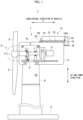
- FIG. 1 is a schematic diagram showing a configuration example of a wind turbine to which a heli-hoist platform according to at least one embodiment of the present disclosure is applied.
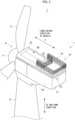
- FIG. 2 is a schematic perspective view showing a configuration example of a heli-hoist platform in one embodiment of the present disclosure.
- a wind power generation facility (hereinafter referred to as a wind turbine 1) according to at least one embodiment of the present disclosure includes: a rotor 4 including at least one wind blade 2, a nacelle 7 rotatably supporting the rotor 4, a tower 8 for supporting the nacelle 7 in a swingable manner, a base 9 on which the tower 8 stands upright.
- the rotor 4 includes, for example, three wind blades 2 and a hub 3 to which the wind blade 2 is attached.
- the rotor 4 is rotatably supported by the nacelle 7 via a drive train 5 including a main shaft 5A coupled to the rotor 4 so as to be integrally rotatable, and an increasing gear 5B.
- the rotational energy of the drive train 5 is converted into electric energy by the generator 6, thereby electric power is generated.
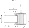
- a heli-hoist platform 10 for a wind turbine includes: a deck plate 12 accessible by a worker P from a helicopter (not shown); a barrier 14 provided along the periphery of the deck plate 12; and a pair of support brackets 16 (see FIG. 5 and FIG. 9 ) extending along a longitudinal direction X of the nacelle 7 at both ends E in a width direction W of the deck plate 12.
- the barrier 14 may include, for example, a handrail, a plate (with holes), a net, a (metal) grid and/or a cooler part.
- an opening 7B (see FIG. 2 , FIG. 3 and FIG. 5 ) is provided for carrying in and out various equipment (not shown) to be installed in the nacelle 7 and for access by workers P.
- the opening 7B may be relatively large and may be provided in the center of a limited space of the roof 70 of the nacelle 7 or from the front to the center in the longitudinal direction X of the nacelle 7.
- the deck plate 12 of the heli-hoist platform 10 provided with the barrier 14 along the periphery thereof is supported by a pair of support brackets 16 extending along the longitudinal direction X of the nacelle 7 at both ends E in the width direction W thereof. That is, the support bracket 16 extending along the longitudinal direction X of the nacelle 7 is not disposed in the center portion in the width direction W of the nacelle 7. Therefore, it is possible to provide a heli-hoist platform 10 that can be attached to the nacelle 7 without hindering the use of the top of the nacelle 7.
- the support bracket 16 can be formed to extend rearward along the longitudinal direction X.
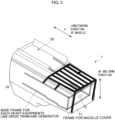
- FIG. 3 shows the frame structure of the nacelle 7.
- the frame in the nacelle 7 mainly includes a support base plate-like portion (base frame portion) for attaching the device and a frame portion for supporting the nacelle cover.
- the support bracket 16 is attached to the frame among the portions.
- the heli-hoist platform 10 is heavy, therefore it is desirable to use a frame that is also supported by the support base plate.
- each of the support brackets 16 may have a connecting portion 24 with the nacelle 7 of the wind turbine 1 (see FIG. 1 ).
- the connecting portion 24 may include a fastening member such as a screw or a bolt nut.
- each support bracket 16 can be connected to the nacelle 7 of the wind turbine 1 via the connecting portion 24.
- the heli-hoist platform 10 for the wind turbine 1 can be attached to the nacelle 7 of the wind turbine 1.
- the worker P can easily access the nacelle 7 via the helicopter without disturbing the use of the central part on the roof 70 of the nacelle 7.
- the heli-hoist platform 10 may further include: a cooler deck 30 positioned behind the deck plate 12; and a pair of extension brackets 18 extending rearward from rear end portions 16A of the pair of support brackets 16 and supporting the cooler deck 30 (see FIG. 1 ).
- the heli-hoist platform 10 is entirely disposed forward if it is attempted to sufficiently secure the space of the deck plate 12. For this reason, it may happen that the space above the nacelle 7 cannot be fully utilized.
- the cooler deck 30 can be supported at the rear position of the deck plate 12 by the extension bracket 18 extending rearward from the rear end portion 16A of each of the pair of support brackets 16. Therefore, for example, when the heli-hoist platform 10 is attached to the nacelle 7 of the wind turbine 1, since the cooler 32 can be placed on the cooler deck 30 located behind the deck plate 12, the use of the central portion on the roof 70 of the nacelle 7 is not hindered, and the cooler 32 can be used on the nacelle 7 without extending the length of the nacelle 7 itself in the longitudinal direction X.
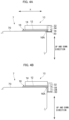
- the bottom of the cooler deck 30 may be positioned at the same height as a rearmost roof surface of the nacelle 7 or lower than the same (see FIG. 4A , for example).
- the cooler deck 30 is disposed at a level approximately equal to or lower than the rearmost end of the roof surface 70 of the nacelle 7 of the wind turbine 1. Therefore, at least a part of the cooler 32 disposed on the cooler deck 30 can be disposed at the same level or below the roof surface 70 of the nacelle 7 behind the deck plate 12. This makes it possible to lower the center of gravity of the cooler 32 and the cooler deck 30 in the wind turbine 1. In addition, for example, since the projected area of the cooler 32 in the front view of the wind turbine 1 can be reduced, the load on the wind turbine structure by the wind can be reduced. Further, for example, by applying the above configuration to each wind turbine constituting the wind farm 40 including the plurality of wind turbines 1, it is possible to improve the power generation efficiency of the entire wind farm 40 by reducing the loss of the downstream flow.
- the bottom of the cooler deck 30 may be positioned lower than the deck plates 12 (see FIGS. 1 , 4B , 7 and 8 , for example).
- the bottom of the cooler deck 30 is disposed below the deck plate 12 and behind the deck plate 12. Therefore, at least a part of the cooler 32 disposed on the cooler deck 30 can be arranged below the deck plate 12 and behind the deck plate 12. This makes it possible to lower the center of gravity of the cooler 32 and the cooler deck 30 in the wind turbine 1, and in addition, for example, when the deck plate 12 is mounted on the nacelle 7, since the project area of the cooler 32 in front view of the wind turbine 1 can be reduced, it is possible to reduce the load due to wind. Further, for example, applying the above configuration to each wind turbine 1 constituting the wind farm 40 including a plurality of wind turbines 1 can reduce the loss of wake flow and improve the power generation efficiency of the entire wind farm 40.
- the pair of support brackets 16 may extend along the longitudinal direction X of the nacelle 7 and may be formed integral or engaged with the front end portions 18A of the extension brackets 18, respectively (see FIGS. 5 and 9 , for example).
- the pair of support brackets 16 are integrally formed or fitted to the front end portions 18A of the pair of extension brackets 18, respectively, it is possible to realize the extension bracket 18 for supporting the cooler deck 30 disposed behind the deck plate 12 with a simple structure in which the extension bracket 18 is integrally or continuously formed or engaged with the support bracket.
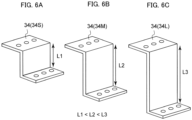
- the cooler deck 30 may be connected to the extension bracket via a support part 34 with a lowering-distance, L, between the extension bracket 18 and the cooler deck 30 (see FIGS. 1 , 4B , 6 and 8 , for example).
- the cooler deck 30 is connected to the extension bracket 18 by the support part 34 with a lowering-distance L between the extension bracket 18 and the cooler deck 30, it is possible to arbitrarily set the lowering-distance L, that is a distance from the extension bracket 18 to the cooler deck 30, by setting the height of the support part 34 in the vertical direction as desired.
- the support part 34 may be configured to be interchangeable between different types in each of which the lowering-distance L from the extension bracket differs (see FIG. 6A, FIG. 6B, and FIG. 6C , for example).
- the support part 34 is interchangeable between a plurality of kinds having different lowering-distance L from the extension bracket 18, it is possible to selectively change the distance from the extension bracket 18 to the cooler deck 30 by interchanging the support parts 34 of the type having different lowering-distance L from the extension bracket 18. Therefore, it is possible to arbitrarily change the lowering-distance L of the cooler deck 30 from the lower end of the support bracket 16 by a simple structure of replacing the support part 34.
- the cooler deck 30 may be configured to be separable from the deck plate 12, and forms scaffold for a worker P during maintenance or inspection of a cooler 32 disposed behind the nacelle 7 (see FIGS. 1 , 4B , 6 and 8 , for example).
- the cooler deck 30 configured to be detachable from the deck plate 12 functions as a scaffold for a worker P at the time of maintenance or inspection of the cooler 32 installed behind the nacelle 7 of the wind turbine 1. Therefore, even when the cooler deck 30 is arranged at different heights with respect to the deck plate 12, the scaffolding of the worker P can be secured at the time of maintenance or inspection of the cooler 32. Thus, it is possible to improve the work efficiency and the safety of the workers P at the time of maintenance or inspection of the cooler 32.
- the heli-hoist platform 10 may further include: a plurality of sub-brackets 20 extending in the width direction W between the pair of support brackets 16 to support the deck plate 12 (see FIG. 5 , for example).
- the frame in the nacelle 7 mainly includes a support base plate-like portion (base frame portion) for attaching the equipment (not shown) to be installed in the nacelle 7 and a frame portion for supporting the nacelle cover. Since the heli-hoist platform 10 is heavy, the sub bracket 20 as well as the support bracket 16 can be attached more firmly to the nacelle 7 when attached to the frame.
- the deck plate 12 can be supported by a plurality of sub-brackets 20 extending in the width direction W of the deck plate 12 in addition to the support bracket 16 extending along the longitudinal direction X at both end portions E in the width direction W of the deck plate 12. Therefore, the deck plate 12 can be supported with a stronger structure than in the case where only the support bracket 16 is used to support the deck plate 12.
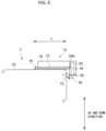
- the heli-hoist platform 10 may further include: a cooler 32 disposed on the upper side of the cooler deck 30; and a piping 36 extending from a device in the nacelle 7 to the cooler 32 (see FIG. 7 , for example).
- the cooler 32 is arranged above the cooler deck 30, and the piping 36 is provided between the cooler 32 and the equipment in the nacelle 7 of the wind turbine 1, it is possible to cool the equipment in the nacelle 7 using a cooler 32 disposed above the cooler deck 30 by configuring the piping 36 provided in this way to circulate the refrigerant, for example. Further, by configuring the equipment in the nacelle 7 so as to be able to be cooled by using the cooler 32 disposed outside the nacelle 7 as described above, the degree of freedom of design regarding the arrangement of the cooler 32 or the equipment or the size of the nacelle 7 itself can be improved.
- the deck plate 12 may include, in a plan view, a recessed portion 22 in a front center area of the deck plate 12 (see FIG. 2 , for example).
- the recessed portion 22 is provided in the front center area of the deck plate 12 in plan view, in the case where an opening 7B for carrying in or carrying out an equipment to be installed inside the nacelle 7 from above is provided on the roof 70 of the nacelle 7, it is possible to reduce or prevent the interference between the deck plate 12 and the door for opening and closing the opening 7B by forming the recessed portion 22 in the deck plate 12 in the above manner, for example.
- the worker P inside the barrier 14 can access at least a part (rear end side of both ends E in the width direction W of the opening 7B, for example) of both ends E in the width direction W of the opening 7B. Therefore, it is possible to improve the working efficiency and improve the safety of the worker P.
- the deck plate 12 may include a pair of hatch portions 26 detachably positioned at both ends E of the recessed portion 22 (see FIG. 9 , for example).
- each of the hatch portions 26 may be positioned in an area surrounded by the barrier 14.
- the platform 10 may be attached to the nacelle proper 7A at a portion forward and higher than the cooler 32 (see FIG. 1 , for example).
- the nacelle proper 7A includes a rear end wall 71 which has an exhaust exit 72 (exhaust opening).
- the nacelle 7 further includes: a hood 38 disposed on the nacelle proper 7A to shroud the exhaust exit 72 from an upward position to guide exhaust gas from the exhaust exit 72 down below the cooler 32 (see FIGS. 2 and 8 , for example).
- a nacelle 7 of the wind turbine 1 capable of obtaining the effect described in any one of the above configurations.
- the exhaust gas discharged from the exhaust exit 72 of the rear end wall 71 of the nacelle proper 7A is guided below the cooler 32 by the hood 38. Therefore, the cooler 32 can be disposed at a position which does not interfere with the exhaust from the exhaust exit 72 at the rear of the nacelle proper 7A.
- a heli-hoist platform 10 that can be attached to the nacelle 7 without disturbing the use of the top of the nacelle 7.
Landscapes
- Engineering & Computer Science (AREA)
- Life Sciences & Earth Sciences (AREA)
- Sustainable Development (AREA)
- Sustainable Energy (AREA)
- Chemical & Material Sciences (AREA)
- Combustion & Propulsion (AREA)
- Mechanical Engineering (AREA)
- General Engineering & Computer Science (AREA)
- Architecture (AREA)
- Civil Engineering (AREA)
- Structural Engineering (AREA)
- Wind Motors (AREA)
Claims (13)
- Helikopterhubplattform (10) für eine Windkraftanlage, umfassend:eine Deckplatte (12), welche für einen Arbeiter von einem Helikopter aus zugänglich ist;eine Barriere (14), welche entlang des Umfangs der Deckplatte bereitgestellt ist; undein Paar von Tragkonsolen (16), welche sich entlang einer Längsrichtung (X) der Helikopterhubplattform an beiden Enden in einer Breitenrichtung (W) der Deckplatte erstreckenein Kühlerdeck, welches hinter der Deckplatte positioniert ist; dadurch gekennzeichnet, dass es weiter umfasst:ein Paar von Verlängerungskonsolen (18), welche sich von hinteren Endabschnitten des Paars von Tragkonsolen (16) nach hinten erstrecken und das Kühlerdeck (30) tragen,wobei eine Unterseite des Kühlerdecks (30) auf der gleichen Höhe wie ein hinterster Teil einer Dachfläche der Gondel (7) oder niedriger als diese liegt.
- Helikopterhubplattform für eine Windkraftanlage nach Anspruch 1,
wobei jeder der Tragkonsolen (16) einen Verbindungsabschnitt (24) mit der Gondel der Windkraftanlage aufweist. - Helikopterhubplattform für eine Windkraftanlage nach Anspruch 1,
wobei eine Unterseite des Kühlerdecks (30) tiefer als die Deckplatten liegt. - Helikopterhubplattform für eine Windkraftanlage nach einem der Ansprüche 1 oder 3,
wobei sich das Paar von Tragkonsolen (16) entlang der Längsrichtung (X) der Gondel erstreckt und einstückig mit den vorderen Endabschnitten der jeweiligen Verlängerungskonsolen ausgebildet ist oder mit diesen in Eingriff steht. - Helikopterhubplattform für eine Windkraftanlage nach einem der Ansprüche 1, 3 oder 4,
wobei das Kühlerdeck (30) mit der Verlängerungskonsole über ein Trageteil (34) verbunden ist, welches sich um einen Abstand zwischen der Unterseite der Tragkonsole (16) und der Unterseite des Kühlerdecks nach unten erstreckt. - Helikopterhubplattform für eine Windkraftanlage nach Anspruch 5,
wobei das Trageteil (34) so konfiguriert ist, dass es unter einer Vielzahl von Typen von Trageteilen mit unterschiedlicher Höhe austauschbar ist. - Helikopterhubplattform für eine Windkraftanlage nach einem der Ansprüche 1 oder 3 bis 6,
wobei das Kühlerdeck so konfiguriert ist, dass es von der Deckplatte trennbar ist, und ein Gerüst für einen Arbeiter während der Wartung oder Inspektion eines hinter der Gondel (7) angeordneten Kühlers (32) bildet. - Helikopterhubplattform für eine Windkraftanlage nach einem der Ansprüche 1 oder 3 bis 7, weiter umfassend:einen Kühler (32), welcher auf der Oberseite des Kühlerdecks angeordnet ist; undeine Rohrleitung, welche sich von einer Vorrichtung in der Gondel (7) zu dem Kühler erstreckt.
- Helikopterhubplattform für eine Windkraftanlage nach einem der Ansprüche 1 bis 8, weiter umfassend:
eine Vielzahl von Unterkonsolen, welche sich in der Breitenrichtung zwischen dem Paar von Tragkonsolen erstrecken, um die Deckplatte (12) zu tragen. - Helikopterhubplattform für eine Windkraftanlage nach einem der Ansprüche 1 bis 9,
wobei die Deckplatte (12) in der Draufsicht einen ausgesparten Abschnitt in einem vorderen mittleren Bereich der Deckplatte beinhaltet. - Helikopterhubplattform für eine Windkraftanlage nach Anspruch 10,
wobei die Deckplatte (12) ein Paar von Lukenabschnitten beinhaltet, welche abnehmbar auf beiden Seiten des ausgesparten Abschnitts in der Breitenrichtung (W) bereitgestellt sind. - Helikopterhubplattform für eine Windkraftanlage nach Anspruch 11,
wobei jeder der Lukenabschnitte in einem Bereich liegt, welcher von der Barriere (14) umgeben ist. - Gondel einer Windkraftanlage, umfassend:einen Gondelkörper;einen Kühler (32), welcher hinter dem Gondelkörper angeordnet ist; undeine Helikopterhubplattform (10) nach einem der Ansprüche 1 bis 12, wobei die Helikopterhubplattform so an dem Gondelkörper befestigt ist, dass sie vor dem Kühler liegt,wobei der Gondelkörper eine hintere Endwand beinhaltet, welche eine Auslassöffnung aufweist, unddie Gondel (7) weiter umfasst:
eine Haube, die auf dem Gondelkörper angeordnet ist, um die Auslassöffnung von oben zu umhüllen, um ein Abgas von der Auslassöffnung nach unten weg von dem Kühler zu leiten.
Applications Claiming Priority (2)
| Application Number | Priority Date | Filing Date | Title |
|---|---|---|---|
| EP18215538 | 2018-12-21 | ||
| PCT/EP2019/084985 WO2020126860A1 (en) | 2018-12-21 | 2019-12-12 | Heli-hoist platform for wind turbine |
Publications (3)
| Publication Number | Publication Date |
|---|---|
| EP3899261A1 EP3899261A1 (de) | 2021-10-27 |
| EP3899261C0 EP3899261C0 (de) | 2024-02-14 |
| EP3899261B1 true EP3899261B1 (de) | 2024-02-14 |
Family
ID=64901880
Family Applications (1)
| Application Number | Title | Priority Date | Filing Date |
|---|---|---|---|
| EP19816784.3A Active EP3899261B1 (de) | 2018-12-21 | 2019-12-12 | Heli-hubplattform für eine windturbine |
Country Status (5)
| Country | Link |
|---|---|
| US (1) | US11608814B2 (de) |
| EP (1) | EP3899261B1 (de) |
| CN (1) | CN113396280A (de) |
| TW (1) | TWI730522B (de) |
| WO (1) | WO2020126860A1 (de) |
Families Citing this family (5)
| Publication number | Priority date | Publication date | Assignee | Title |
|---|---|---|---|---|
| EP3372730A1 (de) * | 2017-03-07 | 2018-09-12 | Adwen GmbH | Klappen von einer gondel und helikopterhebebühne |
| EP4291774B1 (de) | 2021-02-11 | 2024-12-25 | Vestas Wind Systems A/S | Dachgeeignetes hlk-modul für einen windturbinengenerator |
| EP4124751A1 (de) * | 2021-07-30 | 2023-02-01 | General Electric Renovables España S.L. | Hubschrauberhebebühne |
| JP7615081B2 (ja) * | 2022-04-20 | 2025-01-16 | 東光鉄工株式会社 | 風力ブレード点検装置 |
| CN116221044A (zh) * | 2022-12-08 | 2023-06-06 | 远景能源有限公司 | 一种耦合直升机平台的风电机舱散热装置 |
Family Cites Families (29)
| Publication number | Priority date | Publication date | Assignee | Title |
|---|---|---|---|---|
| JPS608566B2 (ja) | 1976-09-04 | 1985-03-04 | 株式会社宝製作所 | レバー式スライドスイッチ |
| US6952058B2 (en) * | 2003-02-20 | 2005-10-04 | Wecs, Inc. | Wind energy conversion system |
| CA2722748A1 (en) * | 2008-04-30 | 2009-11-05 | Multibrid Gmbh | Paneling of a nacelle of a wind energy installation |
| DK2325483T3 (da) * | 2009-11-24 | 2012-11-19 | Siemens Ag | Indretning med en modulær nacelle med en udstråler |
| CN202295334U (zh) * | 2010-12-15 | 2012-07-04 | 西门子公司 | 集成型直升机起落平台 |
| ES2594233T3 (es) * | 2010-12-27 | 2016-12-16 | Areva Wind Gmbh | Instalación de energía eólica con plataforma de transferencia desde helicóptero |
| CN105508154B (zh) * | 2011-02-07 | 2018-02-13 | 菱重维斯塔斯海上风力有限公司 | 具有直升机平台装置的风轮机及其使用方法 |
| CN103492712B (zh) * | 2011-03-30 | 2017-03-01 | 菱重维斯塔斯海上风力有限公司 | 用于风力涡轮机的机舱结构 |
| DK2705251T3 (en) * | 2011-05-04 | 2017-04-10 | Condor Wind Energy Ltd | helipad |
| PL4092265T3 (pl) * | 2011-05-06 | 2024-10-28 | Siemens Gamesa Renewable Energy A/S | Układ chłodzenia turbiny wiatrowej |
| DK2546515T3 (da) * | 2011-07-14 | 2013-11-04 | Siemens Ag | Vindmøllekøleanordning |
| DE102013101239A1 (de) | 2013-02-07 | 2014-08-07 | 2-B Energy Holding B.V. | Windkraftanlage |
| CN106414997B (zh) * | 2013-11-27 | 2018-11-23 | 维斯塔斯风力系统有限公司 | 用于风轮发电机的包括提升设备的机舱 |
| KR102217959B1 (ko) * | 2016-08-29 | 2021-02-22 | 엠에이치아이 베스타스 오프쇼어 윈드 에이/에스 | 풍력 터빈 부품에 대해 유지보수를 수행하는 방법 및 장치 |
| US10982659B2 (en) * | 2016-09-21 | 2021-04-20 | Vestas Wind Systems A/S | Method for opening a cover portion of a wind turbine |
| EP3372730A1 (de) * | 2017-03-07 | 2018-09-12 | Adwen GmbH | Klappen von einer gondel und helikopterhebebühne |
| EP3372824A1 (de) * | 2017-03-07 | 2018-09-12 | Adwen GmbH | Gondelabdeckung für windturbinen |
| EP3372828A1 (de) * | 2017-03-07 | 2018-09-12 | Adwen GmbH | Helikopterhebebühne für windkraftanlagen |
| EP3453867B1 (de) * | 2017-09-06 | 2021-02-17 | Siemens Gamesa Renewable Energy A/S | Plattformstruktur einer windturbinengondel |
| EP3884158B1 (de) * | 2018-11-20 | 2024-06-26 | Vestas Wind Systems A/S | Windturbinenkühlsystem |
| GR20180100563A (el) * | 2018-12-18 | 2020-07-16 | Νικολαος Παναγιωτη Πηττας | Αυτοματο συστημα αποθηκευσης αιολικης και φωτοβολταϊκης ενεργειας για αδιακοπη παραγωγη ηλεκτρικης ενεργειας και παροχη ενεργειακης αυτονομιας |
| CN114729625A (zh) * | 2019-11-22 | 2022-07-08 | 维斯塔斯风力系统有限公司 | 风力涡轮机 |
| CN114901943B (zh) * | 2019-11-26 | 2023-04-11 | 维斯塔斯风力系统有限公司 | 在风力涡轮机塔架中安装线缆和其它部件 |
| US11585325B2 (en) * | 2020-10-28 | 2023-02-21 | General Electric Company | Method and system for cooling a wind turbine gearbox oil heat-exchanger |
| EP3996247A1 (de) * | 2020-11-06 | 2022-05-11 | General Electric Renovables España S.L. | Magnets in electrical machines |
| CA3200230A1 (en) * | 2020-11-30 | 2022-06-02 | John Setel O'donnell | Energy storage system and applications |
| EP4015818B1 (de) * | 2020-12-18 | 2024-10-16 | Wobben Properties GmbH | Windenergieanlage |
| US12196175B2 (en) * | 2021-06-02 | 2025-01-14 | Mammoet Usa South, Inc. | Lift system and method for wind turbine monopiles and other structures |
| US20220396921A1 (en) * | 2021-06-09 | 2022-12-15 | Frank Asamoah Frimpong | Freestanding kojo helipad for vtol flying cars |
-
2019
- 2019-12-03 TW TW108144043A patent/TWI730522B/zh active
- 2019-12-12 CN CN201980090580.9A patent/CN113396280A/zh active Pending
- 2019-12-12 US US17/312,136 patent/US11608814B2/en active Active
- 2019-12-12 EP EP19816784.3A patent/EP3899261B1/de active Active
- 2019-12-12 WO PCT/EP2019/084985 patent/WO2020126860A1/en not_active Ceased
Also Published As
| Publication number | Publication date |
|---|---|
| CN113396280A (zh) | 2021-09-14 |
| EP3899261C0 (de) | 2024-02-14 |
| EP3899261A1 (de) | 2021-10-27 |
| US11608814B2 (en) | 2023-03-21 |
| TW202035859A (zh) | 2020-10-01 |
| WO2020126860A1 (en) | 2020-06-25 |
| TWI730522B (zh) | 2021-06-11 |
| US20220042491A1 (en) | 2022-02-10 |
Similar Documents
| Publication | Publication Date | Title |
|---|---|---|
| EP3899261B1 (de) | Heli-hubplattform für eine windturbine | |
| EP2673499B1 (de) | Windturbine mit heliplatform und verwendungsverfahren dafür | |
| EP2691649B1 (de) | Gondelkonstruktionen für eine windturbine | |
| US7857599B2 (en) | Method and apparatus for forming wind turbine machines | |
| EP2412970A1 (de) | Gondel für eine Windturbine | |
| US20190072084A1 (en) | Wind turbine nacelle platform structure | |
| EP2909471B1 (de) | Windturbine mit wartungsetage | |
| US20190136626A1 (en) | External ladder assembly for wind turbine nacelle | |
| CN117940664A (zh) | 维修风轮机转子叶片的方法 | |
| US11215168B2 (en) | Wind turbine and cooling device for a wind turbine | |
| EP3431757B1 (de) | Externe plattformanordnung für windturbinenreparaturen | |
| CN117957367A (zh) | 临时工作平台组件 | |
| DK202170410A1 (en) | Improvements relating to servicing of wind turbine blades | |
| KR200476912Y1 (ko) | 풍력발전기의 제어기 모듈 고정장치 | |
| KR20240073927A (ko) | 풍력 터빈 블레이드, 사다리 지지 조립체, 풍력 터빈, 및 풍력 터빈의 중공형 블레이드의 내부에 대한 접근을 제공하기 위한 방법 | |
| GB2511341A (en) | A wind turbine comprising a service floor |
Legal Events
| Date | Code | Title | Description |
|---|---|---|---|
| STAA | Information on the status of an ep patent application or granted ep patent |
Free format text: STATUS: UNKNOWN |
|
| STAA | Information on the status of an ep patent application or granted ep patent |
Free format text: STATUS: THE INTERNATIONAL PUBLICATION HAS BEEN MADE |
|
| PUAI | Public reference made under article 153(3) epc to a published international application that has entered the european phase |
Free format text: ORIGINAL CODE: 0009012 |
|
| STAA | Information on the status of an ep patent application or granted ep patent |
Free format text: STATUS: REQUEST FOR EXAMINATION WAS MADE |
|
| 17P | Request for examination filed |
Effective date: 20210618 |
|
| AK | Designated contracting states |
Kind code of ref document: A1 Designated state(s): AL AT BE BG CH CY CZ DE DK EE ES FI FR GB GR HR HU IE IS IT LI LT LU LV MC MK MT NL NO PL PT RO RS SE SI SK SM TR |
|
| DAV | Request for validation of the european patent (deleted) | ||
| DAX | Request for extension of the european patent (deleted) | ||
| RAP1 | Party data changed (applicant data changed or rights of an application transferred) |
Owner name: VESTAS WIND SYSTEMS A/S |
|
| GRAP | Despatch of communication of intention to grant a patent |
Free format text: ORIGINAL CODE: EPIDOSNIGR1 |
|
| STAA | Information on the status of an ep patent application or granted ep patent |
Free format text: STATUS: GRANT OF PATENT IS INTENDED |
|
| INTG | Intention to grant announced |
Effective date: 20231117 |
|
| GRAS | Grant fee paid |
Free format text: ORIGINAL CODE: EPIDOSNIGR3 |
|
| GRAA | (expected) grant |
Free format text: ORIGINAL CODE: 0009210 |
|
| STAA | Information on the status of an ep patent application or granted ep patent |
Free format text: STATUS: THE PATENT HAS BEEN GRANTED |
|
| AK | Designated contracting states |
Kind code of ref document: B1 Designated state(s): AL AT BE BG CH CY CZ DE DK EE ES FI FR GB GR HR HU IE IS IT LI LT LU LV MC MK MT NL NO PL PT RO RS SE SI SK SM TR |
|
| REG | Reference to a national code |
Ref country code: GB Ref legal event code: FG4D |
|
| REG | Reference to a national code |
Ref country code: CH Ref legal event code: EP |
|
| REG | Reference to a national code |
Ref country code: DE Ref legal event code: R096 Ref document number: 602019046611 Country of ref document: DE |
|
| REG | Reference to a national code |
Ref country code: IE Ref legal event code: FG4D |
|
| U01 | Request for unitary effect filed |
Effective date: 20240222 |
|
| U07 | Unitary effect registered |
Designated state(s): AT BE BG DE DK EE FI FR IT LT LU LV MT NL PT SE SI Effective date: 20240301 |
|
| REG | Reference to a national code |
Ref country code: LT Ref legal event code: MG9D |
|
| PG25 | Lapsed in a contracting state [announced via postgrant information from national office to epo] |
Ref country code: IS Free format text: LAPSE BECAUSE OF FAILURE TO SUBMIT A TRANSLATION OF THE DESCRIPTION OR TO PAY THE FEE WITHIN THE PRESCRIBED TIME-LIMIT Effective date: 20240614 |
|
| PG25 | Lapsed in a contracting state [announced via postgrant information from national office to epo] |
Ref country code: GR Free format text: LAPSE BECAUSE OF FAILURE TO SUBMIT A TRANSLATION OF THE DESCRIPTION OR TO PAY THE FEE WITHIN THE PRESCRIBED TIME-LIMIT Effective date: 20240515 |
|
| PG25 | Lapsed in a contracting state [announced via postgrant information from national office to epo] |
Ref country code: RS Free format text: LAPSE BECAUSE OF FAILURE TO SUBMIT A TRANSLATION OF THE DESCRIPTION OR TO PAY THE FEE WITHIN THE PRESCRIBED TIME-LIMIT Effective date: 20240514 Ref country code: HR Free format text: LAPSE BECAUSE OF FAILURE TO SUBMIT A TRANSLATION OF THE DESCRIPTION OR TO PAY THE FEE WITHIN THE PRESCRIBED TIME-LIMIT Effective date: 20240214 |
|
| PG25 | Lapsed in a contracting state [announced via postgrant information from national office to epo] |
Ref country code: ES Free format text: LAPSE BECAUSE OF FAILURE TO SUBMIT A TRANSLATION OF THE DESCRIPTION OR TO PAY THE FEE WITHIN THE PRESCRIBED TIME-LIMIT Effective date: 20240214 |
|
| PG25 | Lapsed in a contracting state [announced via postgrant information from national office to epo] |
Ref country code: RS Free format text: LAPSE BECAUSE OF FAILURE TO SUBMIT A TRANSLATION OF THE DESCRIPTION OR TO PAY THE FEE WITHIN THE PRESCRIBED TIME-LIMIT Effective date: 20240514 Ref country code: NO Free format text: LAPSE BECAUSE OF FAILURE TO SUBMIT A TRANSLATION OF THE DESCRIPTION OR TO PAY THE FEE WITHIN THE PRESCRIBED TIME-LIMIT Effective date: 20240514 Ref country code: IS Free format text: LAPSE BECAUSE OF FAILURE TO SUBMIT A TRANSLATION OF THE DESCRIPTION OR TO PAY THE FEE WITHIN THE PRESCRIBED TIME-LIMIT Effective date: 20240614 Ref country code: HR Free format text: LAPSE BECAUSE OF FAILURE TO SUBMIT A TRANSLATION OF THE DESCRIPTION OR TO PAY THE FEE WITHIN THE PRESCRIBED TIME-LIMIT Effective date: 20240214 Ref country code: GR Free format text: LAPSE BECAUSE OF FAILURE TO SUBMIT A TRANSLATION OF THE DESCRIPTION OR TO PAY THE FEE WITHIN THE PRESCRIBED TIME-LIMIT Effective date: 20240515 Ref country code: ES Free format text: LAPSE BECAUSE OF FAILURE TO SUBMIT A TRANSLATION OF THE DESCRIPTION OR TO PAY THE FEE WITHIN THE PRESCRIBED TIME-LIMIT Effective date: 20240214 |
|
| PG25 | Lapsed in a contracting state [announced via postgrant information from national office to epo] |
Ref country code: PL Free format text: LAPSE BECAUSE OF FAILURE TO SUBMIT A TRANSLATION OF THE DESCRIPTION OR TO PAY THE FEE WITHIN THE PRESCRIBED TIME-LIMIT Effective date: 20240214 |
|
| PG25 | Lapsed in a contracting state [announced via postgrant information from national office to epo] |
Ref country code: PL Free format text: LAPSE BECAUSE OF FAILURE TO SUBMIT A TRANSLATION OF THE DESCRIPTION OR TO PAY THE FEE WITHIN THE PRESCRIBED TIME-LIMIT Effective date: 20240214 |
|
| PG25 | Lapsed in a contracting state [announced via postgrant information from national office to epo] |
Ref country code: SM Free format text: LAPSE BECAUSE OF FAILURE TO SUBMIT A TRANSLATION OF THE DESCRIPTION OR TO PAY THE FEE WITHIN THE PRESCRIBED TIME-LIMIT Effective date: 20240214 |
|
| PG25 | Lapsed in a contracting state [announced via postgrant information from national office to epo] |
Ref country code: CZ Free format text: LAPSE BECAUSE OF FAILURE TO SUBMIT A TRANSLATION OF THE DESCRIPTION OR TO PAY THE FEE WITHIN THE PRESCRIBED TIME-LIMIT Effective date: 20240214 |
|
| PG25 | Lapsed in a contracting state [announced via postgrant information from national office to epo] |
Ref country code: SK Free format text: LAPSE BECAUSE OF FAILURE TO SUBMIT A TRANSLATION OF THE DESCRIPTION OR TO PAY THE FEE WITHIN THE PRESCRIBED TIME-LIMIT Effective date: 20240214 |
|
| PG25 | Lapsed in a contracting state [announced via postgrant information from national office to epo] |
Ref country code: SM Free format text: LAPSE BECAUSE OF FAILURE TO SUBMIT A TRANSLATION OF THE DESCRIPTION OR TO PAY THE FEE WITHIN THE PRESCRIBED TIME-LIMIT Effective date: 20240214 Ref country code: SK Free format text: LAPSE BECAUSE OF FAILURE TO SUBMIT A TRANSLATION OF THE DESCRIPTION OR TO PAY THE FEE WITHIN THE PRESCRIBED TIME-LIMIT Effective date: 20240214 Ref country code: RO Free format text: LAPSE BECAUSE OF FAILURE TO SUBMIT A TRANSLATION OF THE DESCRIPTION OR TO PAY THE FEE WITHIN THE PRESCRIBED TIME-LIMIT Effective date: 20240214 Ref country code: CZ Free format text: LAPSE BECAUSE OF FAILURE TO SUBMIT A TRANSLATION OF THE DESCRIPTION OR TO PAY THE FEE WITHIN THE PRESCRIBED TIME-LIMIT Effective date: 20240214 |
|
| REG | Reference to a national code |
Ref country code: DE Ref legal event code: R097 Ref document number: 602019046611 Country of ref document: DE |
|
| PLBE | No opposition filed within time limit |
Free format text: ORIGINAL CODE: 0009261 |
|
| STAA | Information on the status of an ep patent application or granted ep patent |
Free format text: STATUS: NO OPPOSITION FILED WITHIN TIME LIMIT |
|
| 26N | No opposition filed |
Effective date: 20241115 |
|
| U20 | Renewal fee for the european patent with unitary effect paid |
Year of fee payment: 6 Effective date: 20241225 |
|
| PG25 | Lapsed in a contracting state [announced via postgrant information from national office to epo] |
Ref country code: MC Free format text: LAPSE BECAUSE OF FAILURE TO SUBMIT A TRANSLATION OF THE DESCRIPTION OR TO PAY THE FEE WITHIN THE PRESCRIBED TIME-LIMIT Effective date: 20240214 |
|
| REG | Reference to a national code |
Ref country code: CH Ref legal event code: PL |
|
| GBPC | Gb: european patent ceased through non-payment of renewal fee |
Effective date: 20241212 |
|
| PG25 | Lapsed in a contracting state [announced via postgrant information from national office to epo] |
Ref country code: GB Free format text: LAPSE BECAUSE OF NON-PAYMENT OF DUE FEES Effective date: 20241212 |
|
| PG25 | Lapsed in a contracting state [announced via postgrant information from national office to epo] |
Ref country code: CH Free format text: LAPSE BECAUSE OF NON-PAYMENT OF DUE FEES Effective date: 20241231 |
|
| PG25 | Lapsed in a contracting state [announced via postgrant information from national office to epo] |
Ref country code: IE Free format text: LAPSE BECAUSE OF NON-PAYMENT OF DUE FEES Effective date: 20241212 |