EP3899254B1 - Windturbinensteuerung basierend auf optimierenden und nicht-optimierenden reglerroutinen - Google Patents
Windturbinensteuerung basierend auf optimierenden und nicht-optimierenden reglerroutinen Download PDFInfo
- Publication number
- EP3899254B1 EP3899254B1 EP19827613.1A EP19827613A EP3899254B1 EP 3899254 B1 EP3899254 B1 EP 3899254B1 EP 19827613 A EP19827613 A EP 19827613A EP 3899254 B1 EP3899254 B1 EP 3899254B1
- Authority
- EP
- European Patent Office
- Prior art keywords
- control
- control value
- predicted
- value
- signal
- Prior art date
- Legal status (The legal status is an assumption and is not a legal conclusion. Google has not performed a legal analysis and makes no representation as to the accuracy of the status listed.)
- Active
Links
Images

Classifications
-
- F—MECHANICAL ENGINEERING; LIGHTING; HEATING; WEAPONS; BLASTING
- F03—MACHINES OR ENGINES FOR LIQUIDS; WIND, SPRING, OR WEIGHT MOTORS; PRODUCING MECHANICAL POWER OR A REACTIVE PROPULSIVE THRUST, NOT OTHERWISE PROVIDED FOR
- F03D—WIND MOTORS
- F03D7/00—Controlling wind motors
- F03D7/02—Controlling wind motors the wind motors having rotation axis substantially parallel to the air flow entering the rotor
- F03D7/022—Adjusting aerodynamic properties of the blades
- F03D7/0224—Adjusting blade pitch
-
- F—MECHANICAL ENGINEERING; LIGHTING; HEATING; WEAPONS; BLASTING
- F03—MACHINES OR ENGINES FOR LIQUIDS; WIND, SPRING, OR WEIGHT MOTORS; PRODUCING MECHANICAL POWER OR A REACTIVE PROPULSIVE THRUST, NOT OTHERWISE PROVIDED FOR
- F03D—WIND MOTORS
- F03D7/00—Controlling wind motors
- F03D7/02—Controlling wind motors the wind motors having rotation axis substantially parallel to the air flow entering the rotor
- F03D7/0296—Controlling wind motors the wind motors having rotation axis substantially parallel to the air flow entering the rotor to prevent, counteract or reduce noise emissions
-
- F—MECHANICAL ENGINEERING; LIGHTING; HEATING; WEAPONS; BLASTING
- F03—MACHINES OR ENGINES FOR LIQUIDS; WIND, SPRING, OR WEIGHT MOTORS; PRODUCING MECHANICAL POWER OR A REACTIVE PROPULSIVE THRUST, NOT OTHERWISE PROVIDED FOR
- F03D—WIND MOTORS
- F03D7/00—Controlling wind motors
- F03D7/02—Controlling wind motors the wind motors having rotation axis substantially parallel to the air flow entering the rotor
- F03D7/04—Automatic control; Regulation
- F03D7/042—Automatic control; Regulation by means of an electrical or electronic controller
- F03D7/043—Automatic control; Regulation by means of an electrical or electronic controller characterised by the type of control logic
- F03D7/045—Automatic control; Regulation by means of an electrical or electronic controller characterised by the type of control logic with model-based controls
-
- F—MECHANICAL ENGINEERING; LIGHTING; HEATING; WEAPONS; BLASTING
- F03—MACHINES OR ENGINES FOR LIQUIDS; WIND, SPRING, OR WEIGHT MOTORS; PRODUCING MECHANICAL POWER OR A REACTIVE PROPULSIVE THRUST, NOT OTHERWISE PROVIDED FOR
- F03D—WIND MOTORS
- F03D7/00—Controlling wind motors
- F03D7/02—Controlling wind motors the wind motors having rotation axis substantially parallel to the air flow entering the rotor
- F03D7/04—Automatic control; Regulation
- F03D7/042—Automatic control; Regulation by means of an electrical or electronic controller
- F03D7/047—Automatic control; Regulation by means of an electrical or electronic controller characterised by the controller architecture, e.g. multiple processors or data communications
-
- G—PHYSICS
- G05—CONTROLLING; REGULATING
- G05B—CONTROL OR REGULATING SYSTEMS IN GENERAL; FUNCTIONAL ELEMENTS OF SUCH SYSTEMS; MONITORING OR TESTING ARRANGEMENTS FOR SUCH SYSTEMS OR ELEMENTS
- G05B13/00—Adaptive control systems, i.e. systems automatically adjusting themselves to have a performance which is optimum according to some preassigned criterion
- G05B13/02—Adaptive control systems, i.e. systems automatically adjusting themselves to have a performance which is optimum according to some preassigned criterion electric
- G05B13/04—Adaptive control systems, i.e. systems automatically adjusting themselves to have a performance which is optimum according to some preassigned criterion electric involving the use of models or simulators
- G05B13/048—Adaptive control systems, i.e. systems automatically adjusting themselves to have a performance which is optimum according to some preassigned criterion electric involving the use of models or simulators using a predictor
-
- F—MECHANICAL ENGINEERING; LIGHTING; HEATING; WEAPONS; BLASTING
- F05—INDEXING SCHEMES RELATING TO ENGINES OR PUMPS IN VARIOUS SUBCLASSES OF CLASSES F01-F04
- F05B—INDEXING SCHEME RELATING TO WIND, SPRING, WEIGHT, INERTIA OR LIKE MOTORS, TO MACHINES OR ENGINES FOR LIQUIDS COVERED BY SUBCLASSES F03B, F03D AND F03G
- F05B2270/00—Control
- F05B2270/10—Purpose of the control system
- F05B2270/20—Purpose of the control system to optimise the performance of a machine
-
- F—MECHANICAL ENGINEERING; LIGHTING; HEATING; WEAPONS; BLASTING
- F05—INDEXING SCHEMES RELATING TO ENGINES OR PUMPS IN VARIOUS SUBCLASSES OF CLASSES F01-F04
- F05B—INDEXING SCHEME RELATING TO WIND, SPRING, WEIGHT, INERTIA OR LIKE MOTORS, TO MACHINES OR ENGINES FOR LIQUIDS COVERED BY SUBCLASSES F03B, F03D AND F03G
- F05B2270/00—Control
- F05B2270/30—Control parameters, e.g. input parameters
- F05B2270/334—Vibration measurements
-
- F—MECHANICAL ENGINEERING; LIGHTING; HEATING; WEAPONS; BLASTING
- F05—INDEXING SCHEMES RELATING TO ENGINES OR PUMPS IN VARIOUS SUBCLASSES OF CLASSES F01-F04
- F05B—INDEXING SCHEME RELATING TO WIND, SPRING, WEIGHT, INERTIA OR LIKE MOTORS, TO MACHINES OR ENGINES FOR LIQUIDS COVERED BY SUBCLASSES F03B, F03D AND F03G
- F05B2270/00—Control
- F05B2270/40—Type of control system
- F05B2270/404—Type of control system active, predictive, or anticipative
-
- Y—GENERAL TAGGING OF NEW TECHNOLOGICAL DEVELOPMENTS; GENERAL TAGGING OF CROSS-SECTIONAL TECHNOLOGIES SPANNING OVER SEVERAL SECTIONS OF THE IPC; TECHNICAL SUBJECTS COVERED BY FORMER USPC CROSS-REFERENCE ART COLLECTIONS [XRACs] AND DIGESTS
- Y02—TECHNOLOGIES OR APPLICATIONS FOR MITIGATION OR ADAPTATION AGAINST CLIMATE CHANGE
- Y02E—REDUCTION OF GREENHOUSE GAS [GHG] EMISSIONS, RELATED TO ENERGY GENERATION, TRANSMISSION OR DISTRIBUTION
- Y02E10/00—Energy generation through renewable energy sources
- Y02E10/70—Wind energy
- Y02E10/72—Wind turbines with rotation axis in wind direction
Definitions
- the present invention relates to control of wind turbines, and in particular to wind turbines with control systems comprising both optimizing controller units, such as MPC controller units, and non-optimizing controller units.
- Wind turbines are commonly used to supply electricity into the electrical grid.
- a wind turbine or a wind turbine park is operated with the aim to obtain maximum yield of the capital invested in it, and consequently the wind turbine control systems are configured to maximize the output power, i.e. to operate the wind turbine to capture the maximal power that is available in the wind, with due regard to keeping the wind turbine within operational limits.
- Modern turbines are operated by a number of computerized controllers which based on input signals determines actuator output signals.
- Many turbine controllers are implemented as feedback controllers of the PID-type.
- PID-type controllers are well-known and reliable controllers.
- Wind turbines are quite complex machines operating in complex, varying and often unpredictable environment. There may therefore be an advantage in applying more advanced control techniques of the multiple input, multiple output (MIMO) type.
- MIMO multiple input, multiple output
- MIMO multiple input, multiple output
- One example of such advanced controller is a controller based on the so-called Model Predictive Control (MPC) methodology.
- MIMO multiple input, multiple output
- WO2011/076295 discloses a wind turbine having a control method and controller for performing predictive control, hereunder MPC, of a wind turbine generator based on wind speed obtained at a predetermined distance in front of the rotor.
- WO2016/023561 discloses a wind turbine have a control system arranged for controlling a predicted control trajectory, e.g. by an MPC controller, and a safety controller for controlling the wind turbine in accordance with a safe-mode control trajectory.
- the safe-mode control trajectory may or may not be calculated by an optimizing controller.
- the wind turbine is controlled either based on the predicted control trajectory or based on the safe-mode control trajectory.
- US2017/248124 A1 discloses a control system for a wind turbine where a main controller is calculating predicted control trajectories to be validated by a safety controller.
- the control system controls the wind turbine with the predicted control trajectory if valid otherwise with a safe-mode control trajectory.
- Wind turbine control based on MPC is challenged by the rather involved computations for executing an MPC algorithm for real-time control, where actuator setpoints are often calculated between a few Hz and 100 Hz.
- a wind turbine control system in accordance with claim 1, comprising: a first controller unit implementing a model predictive control (MPC) routine for calculating a predicted operational trajectory of a predicted operational signal, where a trajectory comprises a time series of at least one variable, and where a trajectory includes a predicted first control value; a second controller unit implementing a non-optimizing controller for calculating a second control value; and an actuator controller unit arranged for determining an actuator control signal by combining the predicted first control value and the second control value.
- MPC model predictive control
- actuator control signals can be split up in sub-signals which are determined by different controller units implemented in accordance with different control principles.
- MPC By basing part of the actuator signal on values determined by an MPC routine, the benefits of MPC can be obtained for the selected control variables forming part of the combined actuator control signal, whereas other selected control variables can be handled by the computational simpler non-optimizing control type.
- MPC can be applied for wind turbine control in real-time without relying on computing power that are not available in modern wind turbines.
- certain control aspects may beneficially be handled by a non-optimizing control routine, whereas as other control aspects are beneficially handled by an optimizing control routine.
- Embodiments of the present invention thereby allow for selecting which type of control routine that is used for the different control tasks, irrespectively of the computing power available in the turbine.
- a non-optimizing controller is to be understood as a controller which based on input determines an output, where the output is determined based on a calculation which cannot be understood as a numerical optimization. In particular, which is not based on a real-time optimization or online optimization.
- the non-optimizing controller algorithm may have undergone prior tuning or may include tuning parameters which are varied based on input. Such tuning is not to be understood as an optimization.
- the non-optimizing controller may be based on arithmetic calculations, logical calculations, feedback control loops, feedforward control loop, hereunder PID, PI or other feedback controllers.
- the control system thus comprises three controller units, however further units may be present.
- the first controller unit is an MPC controller
- the second controller unit is a classic controller unit being based on non-optimizing control
- the third controller unit is an actuator controller.
- the actuator controller may be a controller for any actuator in the wind turbine, including but not limited to pitch actuators and power actuators.
- the power actuator may be elements of the generator-converter system which is decisive for the resulting generator torque.
- the generator torque may be controlled via a power setpoint or a torque setpoint received by the converter controller arranged for controlling relevant elements of the generator-converter system. Further actuators may also be envisioned, such as active aerodynamic elements, mechanical damper elements, etc.
- the combination may comprise superposing a mathematical function dependent on the first control value and a mathematical function dependent on the first control value.
- the control system may handle more than two control values and the resulting actuator control signal may be based on a number of predicted control values and a number of further control values being determined by non-optimizing controller units.
- the second control values are determined to reduce out-of-plane rotor forces and/or to reduce tower vibrations.
- the fault signal comprises an override control value to replace the predicted control value, the override control value being the last determined valid predicted control value. This may ensure that, while a current valid control value is not available, the wind turbine is nevertheless being controlled in accordance with a validated control value. A prior determined control value may be valid, but the validity may only last for a given time.
- the fault unit monitors the number of samples passing by without a valid solution being obtained, and if the number of samples is larger than a predefined threshold value, the fault signal is a shutdown signal of the wind turbine. In this manner it can be ensured that the turbine is only operated based on control values to which a high certainty of validity can be assigned.
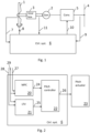
- Figure 1 schematically illustrates an embodiment of a control system 6 together with elements of a wind turbine.
- the wind turbine comprises rotor blades 1 which are mechanically connected to an electrical generator 2 via gearbox 3. In direct drive systems, and other systems, the gear box may not be present.
- the electrical power generated by the generator 2 is injected into a power grid 4 via an electrical converter 5.
- the electrical generator 2 and the converter 5 may be based on a full-scale converter architecture or a doubly fed induction generator (DFIG) architecture, but other types may be used.
- DFIG doubly fed induction generator
- the control system 6 comprises a number of elements, including processor and a memory, so that sub-units of the control system is capable of executing computing tasks based on instructions stored in the memory.
- the wind turbine controller 6 ensures that in operation the wind turbine generates a requested power output level within design limits. This is obtained by adjusting the pitch angle and/or the power extraction of the converter.
- the control system 6 instructs a pitch system using a pitch reference 8, and a power system using a power reference 10.
- the control system receives a number of input signals, hereunder the pitch positions 7 of each rotor blade, the grid power 9, the rotor speed 11.
- a number of other sensor values are made available to the elements of the control system. In the figure two rotor blades are shown, however any number of rotor blades may be used, in particular three rotor blades.
- the wind turbine rotor comprises rotor blades that can be pitched by a pitch mechanism.
- the rotor may comprise a common pitch system which adjusts all pitch angles on all rotor blades at the same time, as well as in addition thereto an individual pitch system which is capable of individual pitching of the rotor blades.
- the split in common pitch system and individual pitch system is to a certain extent logical or controller based, as only a single pitch reference is sent to each pitch actuator of the blades.
- This single pitch reference may be a combined signal of the common pitch reference, the individual pitch reference, and potentially also other contributions.
- the common pitch reference and the individual pitch reference may be based on contributions from different determinations.
- the common pitch is set as a common pitch setting for all blades and is used for controlling the aerodynamic torque of the rotor and the rotor thrust.
- the individual pitch is set as an individual pitch setting for each blade.
- the individual pitch may be implemented as a cyclic pitch setting which is based on a common reference value that is phase adjusted 120°. The phase adjusted signal will impose a cyclic variation if super-imposed on the collective pitch.
- the individual pitch system is often used for load relieving activities.
- Figure 2 illustrates an embodiment of the wind turbine control system 6 comprising a first controller unit 20 implemented as an MPC controller unit to calculate a predicted control value 24 and a second non-optimizing controller unit 21 implemented to calculate a second control value 25.
- the MPC controller unit 20 is implemented for calculating the predicted control value in the form of the collective pitch reference
- the second controller 21 is implemented for calculating a different second control value in the form of a pitch signals for reducing the lateral tower vibrations.
- the two controllers are implemented to operate in parallel, meaning that they are both active at the same time being able to operate in an independent manner.
- the MPC routine and the non-optimizing control routine are based on various inputs 27-29, such as turbine state input, sensor input, actuator input.
- the inputs may be input 27 dedicated to the MPC, input 28 dedicated to the non-optimizing control routine, or shared input 29.
- Figure 3 further illustrates elements of the embodiment of Fig. 2 , including signals involved in determining the pitch actuator control signal.
- the collective pitch signal determined by the MPC and the lateral damping signal determined by the lateral tower vibration unit are input to an actuator controller unit 22 which combines the two signals to generate an actuator control signal 26 for the pitch actuator 23.
- the operational trajectory is a predicted operational state trajectory.
- a state is a collection, often expressed as a vector, of operational parameters.
- Other and more parameters may be used to define the wind turbine state, x *.
- the operational trajectory includes operational parameters which are used to calculate the desired fatigue load measure.
- the state values of the current operational state of the wind turbine may be based on measured sensor readings from sensors arranged to measure sensor data relating to the wind turbine's physical state values. Additionally, estimated values or calculated values may also be used.
- the state may be determined by a state calculator, e.g. in the form of a dedicated computational unit in charge of determining the current operational state, such as an observer or a Kalman filter.
- the trajectory may be expressed as a control trajectory.
- Figure 3 shows a trajectory 31 of a control value for a number of discrete time steps.
- the figure shows the current time, k, as well as a number of past time steps and a number of future time steps 32.
- Known values are marked with a solid circle, whereas predicted values are marked with an open circle.
- a trajectory may comprise a time series of predicted values, i.e. only the open circles. The trajectory need not include the past and known values, but may do in certain embodiments.
- the trajectory may span a time series of a few seconds, such as 5-10 seconds. However, the trajectory may be longer or shorter depending on the given implementation.
- Model Predictive Control is a multi variable control algorithm that uses an optimization cost function J over the receding prediction horizon, to calculate the optimal control moves.
- r i is the set-point for the i -th variable
- y i and u i being i -th trajectory variables
- w y i being weight matrix defining the relative importance of this variable
- w u i being weight matrix defining the penalty related to changes in this variable.
- the MPC may be implemented as a so-called economic optimizing MPC or just economic MPC.
- economic MPC the optimization is based on a maximization of the cost function on the form: maximize Power ⁇ ⁇ 1 Fatique ⁇ ⁇ 2 Noise ⁇ ⁇ 3 Pitch rate ⁇ ... , where ⁇ 1 - ⁇ 3 are tuneables.
- cost function is often called an objective function.
- the optimization problem may in an embodiment be solved by a change of variables, to a formulation where the pitch and torque are treated as variables derived from the powers, e.g. in a parameter space where generator power, power extracted from the wind and kinetic energy is optimized.
- a change of variables to a formulation where the pitch and torque are treated as variables derived from the powers, e.g. in a parameter space where generator power, power extracted from the wind and kinetic energy is optimized.
- the MPC calculation may comprise three layers: a pre-processing layer, a solving layer and a post-processing layer. In the pre-processing such steps as transformation of the measured values of pitch and generator speed into corresponding powers. Also constraints are determined, the turbine state is estimated, etc.
- a result of the pre-processing is that the objective function is defined in a form which can be input into a solver.
- a maximum of the objectivity function is found.
- the solver being a computing unit arranged to find an optimum, preferably a global optimum of the objective function. This optimum, will be an optimum expressed in power variables.
- the optimizing values are back-transformed into the control values in the form of pitch and generator speed. These optimized values are then used in the control.
- the MPC controller 20 operates at a first sampling rate. Due to the rather heavy computations that are involved in the optimization of the cost function, the sampling rate is normally set at a compromise between available computing resources and ideal sampling rate.
- the non-optimizing controller is typically not limited in sampling rate since the involved computations are of the digital filter type, such as FFT, band pass filtering, as well as arithmetic calculations. In an example, the sampling rate of the MPC controller is a few Hz, whereas the sampling rate of the non-optimizing controller is a few tens of Hz.
- the actuator controller unit 22 comprises a sampling unit 33 which is arranged for receiving the predicted first control value at a first sampling rate and the second control value at a second sample rate.
- the sampling unit is arranged for adjusting the sampling rate of at least one of the predicted first control value and the second control value to output the actuator control signal at an output sample rate.
- the sampling rate of the predicted first control value is adjusted to match the second control value, so that the sampling rate of the pitch actuator match the sampling rate of the non-optimizing controller.
- the sampling unit 33 operates as an up-sampling unit, but may alternatively also operate as a down-sampling unit.
- the sampling unit is implemented in a manner so that it can take signals at different sampling rates and output a combined signal at a selected output sample rate.
- the output sample rate being selected so that it matches the relevant sampling rate of the actuator in question, here the pitch actuator.
- the model predictive control routine 20 is implemented for online optimization.
- the MPC controller is determining control values for real-time use, for example as mentioned, control values at a sampling rate between a few Hz and 100 Hz.
- the fault unit stores at least the values of the last valid prediction horizon, and in the event a valid current value is not available, the fault signal is an override control value to replace the predicted control value, the override control value being the last determined valid predicted control value, i.e. the values 31 of the last valid prediction horizon.
- the fault unit monitors the number of samples passing by without a valid solution being obtained, and if the number of samples is larger than a predefined threshold value, the fault signal is a shutdown signal of the wind turbine. For example, if 5 samples having passed without a valid new solution, the turbine is shutdown.
- the first couple of values in the prediction horizon may be of sufficient credibility that the turbine may operate based on those.
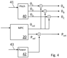
- Figure 4 illustrates an embodiment where the MPC is implemented to output two predicted control values, i.e. a first predicted control value and a second predicted control value.
- One predicted control value is the collective pitch, ⁇ col
- one predicted control value is the output power reference for the generator P ref .
- Figure 4 further shows two non-optimizing controllers.
- the individual pitch contribution may in embodiments be determined as cyclic varying values super-imposed onto the collective pitch value to provide actuator values ⁇ A - ⁇ C for the three pitch actuators.
- the individual pitch contributions may in embodiments be determined for a number of reasons. Depending on the object of the individual pitch contributions, different input signals 41 may be used by the individual pitch controller.
- the individual pitch contributions may be determined to reduce shear or veer.
- angular position in the rotor plane or blade load sensors may be used as input, and based on that an individual pitch contribution is determined to reduce the shear or veer.
- the individual pitch contribution may be of tower load reducing nature, such as vibrational damping of tower movement.
- the input may be accelerometer data
- the output is individual pitch contributions which generates a force in the relevant direction.
- the output may be a single pitch modulation to modulate the collective pitch to provide a thrust modulation onto the rotor.
- a controller implemented to take one or more inputs 41 and provide individual pitch contributions as output ( ⁇ 1 , ⁇ 2 , ⁇ 3 ).
- the individual pitch contributions are super-imposed onto the collective pitch value ⁇ col to provide actuator control signals, here in the form of three pitch actuator signals ( ⁇ A , ⁇ B , ⁇ C ) for the pitch actuators of the individual blades.
- a second controller unit 42 for calculating a control value for modifying the predicted power reference (P ref ).
- the power controller is a controller for calculating a signal for reducing sideways tower vibrations.
- a signal representing sideways tower vibrations e.g. an accelerometer signal
- cyclic power variation for reducing the tower vibrations is calculated and super-imposed to the power refence to provide a power setpoint, P set .
- the power setpoint being a signal with a DC component corresponding to the power reference, and an overlaying power modulation to reduce sideways tower movement.
- the power controller is a controller for calculating a temporary power boost.
- the input may be an external communication input requesting a temporary over-production. In this situation the power controller calculates a power pulse to be super-imposed onto the power reference.
Landscapes
- Engineering & Computer Science (AREA)
- Life Sciences & Earth Sciences (AREA)
- Sustainable Development (AREA)
- Sustainable Energy (AREA)
- Chemical & Material Sciences (AREA)
- Combustion & Propulsion (AREA)
- Mechanical Engineering (AREA)
- General Engineering & Computer Science (AREA)
- Physics & Mathematics (AREA)
- Fluid Mechanics (AREA)
- Health & Medical Sciences (AREA)
- Artificial Intelligence (AREA)
- Computer Vision & Pattern Recognition (AREA)
- Evolutionary Computation (AREA)
- Medical Informatics (AREA)
- Software Systems (AREA)
- General Physics & Mathematics (AREA)
- Automation & Control Theory (AREA)
- Wind Motors (AREA)
Claims (12)
- Windkraftanlagensteuersystem (6), umfassend:eine erste Steuereinheit (24), die eine modellprädiktive Steuerroutine (MPC-Routine) zum Berechnen einer prädizierten Betriebstrajektorie (31) eines prädizierten Betriebssignals implementiert, wobei eine Trajektorie eine Zeitreihe von mindestens einer Variablen umfasst, und wobei eine Trajektorie einen prädizierten ersten Steuerwert (24) beinhaltet;eine zweite Steuereinheit (21), die eine nicht-optimierende Steuervorrichtung implementiert, um einen zweiten Steuerwert (25) zu berechnen; undeine Betätigungssteuereinheit (22), die zum Bestimmen eines Betätigungssteuersignals (26) durch Kombinieren des prädizierten ersten Steuerwerts und des zweiten Steuerwerts angeordnet ist,dadurch gekennzeichnet, dassdie erste Steuereinheit weiter eine Fehlereinheit umfasst, die angeordnet ist, um eine Optimierungsroutine der MPC-Routine zu überwachen und, wenn die Optimierungsroutine während einer vorgegebenen Zeit keine gültige Lösung für die Optimierung bereitstellt, ein Fehlersignal auszusenden, wobei das Fehlersignal einen Übersteuerungssteuerwert umfasst, um den prädizierten ersten Steuerwert zu ersetzen, wobei der Übersteuerungssteuerwert der letzte bestimmte gültige prädizierte Steuerwert ist, unddass die Fehlereinheit angeordnet ist, um die Anzahl der Abtastungen zu überwachen, die durchlaufen werden, ohne dass eine gültige Lösung erhalten wird, und wenn die Anzahl der Abtastungen größer als ein vordefinierter Schwellenwert ist, ist das Fehlersignal ein Abschaltsignal der Windkraftanlage.
- Steuersystem nach Anspruch 1, wobei die Betätigungssteuereinheit (22) eine Abtasteinheit (33) umfasst, die zum Empfangen des prädizierten ersten Steuerwerts mit einer ersten Abtastrate angeordnet ist und zum Empfangen des zweiten Steuerwerts mit einer zweiten Abtastrate angeordnet ist, und wobei die Abtasteinheit zum Anpassen der Abtastrate von mindestens einem des prädizierten ersten Steuerwerts und des zweiten Steuerwerts angeordnet ist, um das Betätigungssteuersignal mit einer Ausgangsabtastrate auszugeben.
- Steuersystem nach einem der vorstehenden Ansprüche, wobei sich der prädizierte Steuerwert auf einen ersten Steuerwert bezieht, und wobei sich der zweite Steuerwert auf einen zweiten Steuerwert bezieht, wobei der erste und der zweite Steuerwert unterschiedliche Steuerwerte sind.
- Steuersystem nach einem der vorstehenden Ansprüche, wobei die modellprädiktive Steuerroutine zur Online-Optimierung implementiert ist.
- Steuersystem nach einem der vorstehenden Ansprüche, wobei die erste und die zweite Steuervorrichtung für einen Parallelbetrieb implementiert sind.
- Steuersystem nach einem der vorstehenden Ansprüche, wobei der prädizierte erste Steuerwert mindestens einer von dem Steuerwert zum Einstellen des gemeinsamen Blattwinkels (θcol) und dem Steuerwert zum Einstellen der Ausgangsleistung (Pref) ist.
- Steuersystem nach einem der vorstehenden Ansprüche, wobei der prädizierte erste Steuerwert der Steuerwert zum Einstellen des gemeinsamen Blattwinkels (θcol) ist und der zweite Steuerwert ein zyklisch variierender Wert (θ1, θ2, θ3) zum Überlagern der zyklischen Blattwinkelvariation auf den Wert des gemeinsamen Blattwinkels ist.
- Steuersystem nach einem der vorstehenden Ansprüche, wobei der prädizierte erste Steuerwert der Steuerwert zum Einstellen der Ausgangsleistung (Pref) ist und der zweite Steuerwert ein zyklisch variierender Wert zum Überlagern einer zyklischen Leistungsvariation auf die Ausgangsleistung ist.
- Steuersystem nach Anspruch 7, wobei zweite Steuerwerte bestimmt werden, um die Kräfte außerhalb der Rotorebene zu reduzieren.
- Steuersystem nach Anspruch 7 oder 8, wobei zweite Steuerwerte bestimmt werden, um Turmschwingungen zu reduzieren.
- Steuersystem nach einem der vorstehenden Ansprüche, wobei die zweiten Steuerwerte Werte sind, die sich auf die Überwachung beziehen, um ein vordefiniertes Betätigungssteuersignal im Hinblick auf einen Windkraftanlagenzustand zu gewährleisten, der außerhalb eines vordefinierten, von einem zugeordneten Überwachungssystem überwachten Betriebszustands liegt.
- Verfahren zur Steuerung eines Windkraftanlagensteuersystems (6), wobei das Verfahren umfasst:Berechnen, unter Verwendung einer modellprädiktiven Steuerroutine (MPC-Routine), einer prädizierten Betriebstrajektorie (31) eines prädizierten Betriebssignals, wobei eine Trajektorie eine Zeitreihe von mindestens einer Variablen umfasst, und wobei eine Trajektorie einen prädizierten ersten Steuerwert (24) beinhaltet;Berechnen, unter Verwendung einer nicht-optimierenden Steuerroutine, eines zweiten Steuerwerts (25); undKombinieren des prädizierten ersten Steuerwerts und des zweiten Steuerwerts zu einem Betätigungssteuersignal (26),dadurch gekennzeichnet, dassdas Verfahren weiter, in einer Fehlereinheit, das Überwachen einer Optimierungsroutine der MPC-Routine umfasst, und wenn die Optimierungsroutine während einer vorgegebenen Zeit keine gültige Lösung für die Optimierung bereitstellt, Aussenden eines Fehlersignals, wobei das Fehlersignal einen Übersteuerungssteuerwert umfasst, um den prädizierten ersten Steuerwert zu ersetzen, wobei der Übersteuerungssteuerwert der letzte bestimmte gültige prädizierte Steuerwert ist, unddass das Verfahren, in der Fehlereinheit, das Überwachen der Anzahl von Abtastungen umfasst, die durchlaufen werden, ohne dass eine gültige Lösung erhalten wird, und wenn die Anzahl der Abtastungen größer als ein vordefinierter Schwellenwert ist, ist das Fehlersignal ein Abschaltsignal der Windkraftanlage.
Applications Claiming Priority (2)
| Application Number | Priority Date | Filing Date | Title |
|---|---|---|---|
| DKPA201870848 | 2018-12-21 | ||
| PCT/DK2019/050406 WO2020125901A1 (en) | 2018-12-21 | 2019-12-17 | Wind turbine control based on optimising and non-optimising controller routines |
Publications (3)
| Publication Number | Publication Date |
|---|---|
| EP3899254A1 EP3899254A1 (de) | 2021-10-27 |
| EP3899254B1 true EP3899254B1 (de) | 2025-07-09 |
| EP3899254C0 EP3899254C0 (de) | 2025-07-09 |
Family
ID=69005191
Family Applications (1)
| Application Number | Title | Priority Date | Filing Date |
|---|---|---|---|
| EP19827613.1A Active EP3899254B1 (de) | 2018-12-21 | 2019-12-17 | Windturbinensteuerung basierend auf optimierenden und nicht-optimierenden reglerroutinen |
Country Status (5)
| Country | Link |
|---|---|
| US (1) | US12196177B2 (de) |
| EP (1) | EP3899254B1 (de) |
| CN (1) | CN113439159B (de) |
| ES (1) | ES3035804T3 (de) |
| WO (1) | WO2020125901A1 (de) |
Families Citing this family (6)
| Publication number | Priority date | Publication date | Assignee | Title |
|---|---|---|---|---|
| EP3899254B1 (de) * | 2018-12-21 | 2025-07-09 | Vestas Wind Systems A/S | Windturbinensteuerung basierend auf optimierenden und nicht-optimierenden reglerroutinen |
| ES2875674B2 (es) * | 2020-05-07 | 2022-03-21 | Univ Del Pais Vasco / Euskal Herriko Unibertsitatea | Método de control predictivo basado en modelo para la reducción de carga estructural en turbinas eólicas, y turbina configurada para aplicar este método |
| EP4179197B1 (de) | 2020-07-10 | 2025-05-14 | Vestas Wind Systems A/S | Seitliche schwingungssteuerung für einen drosselungswindturbinenturm |
| EP4392666B1 (de) | 2021-08-26 | 2026-03-11 | Vestas Wind Systems A/S | Hilfssteuerung für windturbinensteuerungssystem |
| CN115263669B (zh) * | 2022-06-23 | 2025-02-28 | 广东电网有限责任公司 | 一种海上风电机组的功率控制方法、装置以及系统 |
| CN117028145B (zh) * | 2023-10-08 | 2023-12-22 | 国网江苏省电力有限公司电力科学研究院 | 考虑塔架载荷抑制的风电机组有功功率控制方法及装置 |
Family Cites Families (31)
| Publication number | Priority date | Publication date | Assignee | Title |
|---|---|---|---|---|
| US6295808B1 (en) * | 1999-06-29 | 2001-10-02 | Hereaus Electro-Nite International N.V. | High driveability index fuel detection by exhaust gas temperature measurement |
| US6701214B1 (en) * | 2000-04-27 | 2004-03-02 | Rockwell Automation Technologies, Inc. | Driver board control system for modular conveyer with address-based network for inter-conveyor communication |
| US6717537B1 (en) * | 2001-06-26 | 2004-04-06 | Sonic Innovations, Inc. | Method and apparatus for minimizing latency in digital signal processing systems |
| US7085692B2 (en) * | 2001-10-11 | 2006-08-01 | Xerox Corporation | Learning systems and methods for market-based control of smart matter |
| JP4548767B2 (ja) * | 2004-01-28 | 2010-09-22 | ルネサスエレクトロニクス株式会社 | サンプリングレート変換装置及びサンプリングレート変換方法 |
| ES2418368T3 (es) * | 2005-10-17 | 2013-08-13 | Vestas Wind Systems A/S | Pala de turbina eólica con perfil aerodinámico variable |
| JP4814644B2 (ja) * | 2006-02-01 | 2011-11-16 | 富士重工業株式会社 | 風力発電装置 |
| US7587253B2 (en) * | 2006-08-01 | 2009-09-08 | Warf (Wisconsin Alumni Research Foundation) | Partial enumeration model predictive controller |
| US8185217B2 (en) * | 2008-01-31 | 2012-05-22 | Fisher-Rosemount Systems, Inc. | Robust adaptive model predictive controller with tuning to compensate for model mismatch |
| DE102008009740A1 (de) * | 2008-02-18 | 2009-08-20 | Imo Holding Gmbh | Windkraftanlage sowie Verfahren zum Betrieb derselben |
| US7930045B2 (en) * | 2008-10-07 | 2011-04-19 | Emerson Process Management Power & Water Solutions, Inc. | Two-stage model predictive control technique |
| GB2476316B (en) | 2009-12-21 | 2014-07-16 | Vestas Wind Sys As | A wind turbine having a control method and controller for predictive control of a wind turbine generator |
| US9605558B2 (en) | 2013-08-20 | 2017-03-28 | General Electric Company | System and method for preventing excessive loading on a wind turbine |
| EP2955368A1 (de) * | 2014-06-10 | 2015-12-16 | ABB Technology AG | Optimaler Windparkbetrieb |
| US9897984B2 (en) * | 2014-08-05 | 2018-02-20 | Mitsubishi Electric Research Laboratories, Inc. | Model predictive control with uncertainties |
| EP3180515B1 (de) | 2014-08-15 | 2019-12-04 | Vestas Wind Systems A/S | Steuerung einer windturbine auf basis der validierung einer operationellen flugbahn |
| ES2762519T3 (es) * | 2014-08-15 | 2020-05-25 | Vestas Wind Sys As | Control de un aerogenerador con una condición de fallo |
| US9784241B2 (en) * | 2014-08-25 | 2017-10-10 | General Electric Company | System and method for controlling a wind turbine |
| CN107667220B (zh) * | 2015-05-27 | 2020-06-16 | 维斯塔斯风力系统集团公司 | 考虑疲劳量度的风力涡轮机控制 |
| EP3356671B1 (de) * | 2015-09-28 | 2019-11-06 | Vestas Wind Systems A/S | Schnell reagierendes steuerungssystem für eine windturbine |
| US11053918B2 (en) * | 2016-05-25 | 2021-07-06 | Vestas Wind Systems A/S | Wind turbine control system comprising improved upsampling technique |
| JP6859633B2 (ja) * | 2016-09-05 | 2021-04-14 | オムロン株式会社 | モデル予測制御装置、モデル予測制御装置の制御方法、情報処理プログラム、および記録媒体 |
| US10509843B2 (en) * | 2016-10-28 | 2019-12-17 | Salesforce.Com, Inc. | Systems and methods for managing tabs in web applications |
| JP2019021087A (ja) * | 2017-07-19 | 2019-02-07 | オムロン株式会社 | 制御装置、制御装置の制御方法、情報処理プログラム、および記録媒体 |
| US11613015B2 (en) * | 2017-09-18 | 2023-03-28 | Telefonaktiebolaget Lm Ericsson (Publ) | Technique for providing reliable control in a cloud robotics system |
| JP6937658B2 (ja) * | 2017-10-17 | 2021-09-22 | 日立Astemo株式会社 | 予測制御装置及び方法 |
| JP6888564B2 (ja) * | 2018-02-13 | 2021-06-16 | オムロン株式会社 | モデル予測制御装置、モデル予測制御装置の制御方法、情報処理プログラム、および記録媒体 |
| DE102018005134A1 (de) * | 2018-06-28 | 2020-01-02 | Senvion Gmbh | Verfahren und Steuerung zum Betreiben einer Windenergieanlage |
| KR20200066751A (ko) * | 2018-11-30 | 2020-06-11 | 현대자동차주식회사 | 차량의 엔진 제어방법 |
| EP3899254B1 (de) | 2018-12-21 | 2025-07-09 | Vestas Wind Systems A/S | Windturbinensteuerung basierend auf optimierenden und nicht-optimierenden reglerroutinen |
| US11573023B2 (en) * | 2021-03-07 | 2023-02-07 | Mitsubishi Electric Research Laboratories, Inc. | Controlling vapor compression system using probabilistic surrogate model |
-
2019
- 2019-12-17 EP EP19827613.1A patent/EP3899254B1/de active Active
- 2019-12-17 WO PCT/DK2019/050406 patent/WO2020125901A1/en not_active Ceased
- 2019-12-17 ES ES19827613T patent/ES3035804T3/es active Active
- 2019-12-17 US US17/417,084 patent/US12196177B2/en active Active
- 2019-12-17 CN CN201980092269.8A patent/CN113439159B/zh active Active
Also Published As
| Publication number | Publication date |
|---|---|
| CN113439159A (zh) | 2021-09-24 |
| EP3899254A1 (de) | 2021-10-27 |
| US12196177B2 (en) | 2025-01-14 |
| US20220082083A1 (en) | 2022-03-17 |
| EP3899254C0 (de) | 2025-07-09 |
| ES3035804T3 (en) | 2025-09-09 |
| CN113439159B (zh) | 2024-09-24 |
| WO2020125901A1 (en) | 2020-06-25 |
Similar Documents
| Publication | Publication Date | Title |
|---|---|---|
| US12196177B2 (en) | Wind turbine control based on optimicing and non-optimicing controller routines | |
| EP3303834B1 (de) | Steuerung einer windturbine unter berücksichtigung von ermüdungsmessungen | |
| EP3274584B1 (de) | Steuerung einer windturbine mit mehreren rotoren mittels eines zentralen steuergeräts zur berechnung der lokalen steuerziele | |
| US11118568B2 (en) | Control of a wind turbine with a fault condition | |
| EP3500751B1 (de) | Dynamische gesteuerten abschalten einer windturbine | |
| EP3440346B1 (de) | Steuerung einer windturbine unter berücksichtigung von geräuschen | |
| EP3180515B1 (de) | Steuerung einer windturbine auf basis der validierung einer operationellen flugbahn | |
| US20180266392A1 (en) | Power boost of a wind turbine using model predictive control | |
| CA2664279A1 (en) | Control system for a wind turbine | |
| US11125209B2 (en) | Controlling a wind turbine during a low voltage grid event using MPC | |
| US10465659B2 (en) | Fast reacting control system for wind turbine | |
| EP4112919B1 (de) | Steuerung eines mehrkanal-windturbinensystems unter verwendung lokaler mpc-regler | |
| EP4166782A1 (de) | Prädiktive steuerung für windturbinenmodelle (mpc) mit schub- und/oder leistungskorrektur | |
| CN118462476A (zh) | 用于避免风能设备的机械振荡的方法 | |
| DK201570721A1 (en) | CONTROL OF A WIND TURBINE TAKING FATIGUE MEASURE INTO ACCOUNT |
Legal Events
| Date | Code | Title | Description |
|---|---|---|---|
| STAA | Information on the status of an ep patent application or granted ep patent |
Free format text: STATUS: UNKNOWN |
|
| STAA | Information on the status of an ep patent application or granted ep patent |
Free format text: STATUS: THE INTERNATIONAL PUBLICATION HAS BEEN MADE |
|
| PUAI | Public reference made under article 153(3) epc to a published international application that has entered the european phase |
Free format text: ORIGINAL CODE: 0009012 |
|
| STAA | Information on the status of an ep patent application or granted ep patent |
Free format text: STATUS: REQUEST FOR EXAMINATION WAS MADE |
|
| 17P | Request for examination filed |
Effective date: 20210701 |
|
| AK | Designated contracting states |
Kind code of ref document: A1 Designated state(s): AL AT BE BG CH CY CZ DE DK EE ES FI FR GB GR HR HU IE IS IT LI LT LU LV MC MK MT NL NO PL PT RO RS SE SI SK SM TR |
|
| DAV | Request for validation of the european patent (deleted) | ||
| DAX | Request for extension of the european patent (deleted) | ||
| STAA | Information on the status of an ep patent application or granted ep patent |
Free format text: STATUS: EXAMINATION IS IN PROGRESS |
|
| 17Q | First examination report despatched |
Effective date: 20231211 |
|
| GRAP | Despatch of communication of intention to grant a patent |
Free format text: ORIGINAL CODE: EPIDOSNIGR1 |
|
| STAA | Information on the status of an ep patent application or granted ep patent |
Free format text: STATUS: GRANT OF PATENT IS INTENDED |
|
| INTG | Intention to grant announced |
Effective date: 20250408 |
|
| GRAS | Grant fee paid |
Free format text: ORIGINAL CODE: EPIDOSNIGR3 |
|
| GRAA | (expected) grant |
Free format text: ORIGINAL CODE: 0009210 |
|
| STAA | Information on the status of an ep patent application or granted ep patent |
Free format text: STATUS: THE PATENT HAS BEEN GRANTED |
|
| AK | Designated contracting states |
Kind code of ref document: B1 Designated state(s): AL AT BE BG CH CY CZ DE DK EE ES FI FR GB GR HR HU IE IS IT LI LT LU LV MC MK MT NL NO PL PT RO RS SE SI SK SM TR |
|
| REG | Reference to a national code |
Ref country code: GB Ref legal event code: FG4D |
|
| REG | Reference to a national code |
Ref country code: CH Ref legal event code: EP |
|
| REG | Reference to a national code |
Ref country code: IE Ref legal event code: FG4D |
|
| REG | Reference to a national code |
Ref country code: DE Ref legal event code: R096 Ref document number: 602019072378 Country of ref document: DE |
|
| U01 | Request for unitary effect filed |
Effective date: 20250716 |
|
| U07 | Unitary effect registered |
Designated state(s): AT BE BG DE DK EE FI FR IT LT LU LV MT NL PT RO SE SI Effective date: 20250723 |
|
| REG | Reference to a national code |
Ref country code: ES Ref legal event code: FG2A Ref document number: 3035804 Country of ref document: ES Kind code of ref document: T3 Effective date: 20250909 |
|
| PG25 | Lapsed in a contracting state [announced via postgrant information from national office to epo] |
Ref country code: IS Free format text: LAPSE BECAUSE OF FAILURE TO SUBMIT A TRANSLATION OF THE DESCRIPTION OR TO PAY THE FEE WITHIN THE PRESCRIBED TIME-LIMIT Effective date: 20251109 |
|
| PGFP | Annual fee paid to national office [announced via postgrant information from national office to epo] |
Ref country code: GB Payment date: 20251223 Year of fee payment: 7 |
|
| PG25 | Lapsed in a contracting state [announced via postgrant information from national office to epo] |
Ref country code: NO Free format text: LAPSE BECAUSE OF FAILURE TO SUBMIT A TRANSLATION OF THE DESCRIPTION OR TO PAY THE FEE WITHIN THE PRESCRIBED TIME-LIMIT Effective date: 20251009 |
|
| PG25 | Lapsed in a contracting state [announced via postgrant information from national office to epo] |
Ref country code: HR Free format text: LAPSE BECAUSE OF FAILURE TO SUBMIT A TRANSLATION OF THE DESCRIPTION OR TO PAY THE FEE WITHIN THE PRESCRIBED TIME-LIMIT Effective date: 20250709 |
|
| PG25 | Lapsed in a contracting state [announced via postgrant information from national office to epo] |
Ref country code: GR Free format text: LAPSE BECAUSE OF FAILURE TO SUBMIT A TRANSLATION OF THE DESCRIPTION OR TO PAY THE FEE WITHIN THE PRESCRIBED TIME-LIMIT Effective date: 20251010 |
|
| PG25 | Lapsed in a contracting state [announced via postgrant information from national office to epo] |
Ref country code: PL Free format text: LAPSE BECAUSE OF FAILURE TO SUBMIT A TRANSLATION OF THE DESCRIPTION OR TO PAY THE FEE WITHIN THE PRESCRIBED TIME-LIMIT Effective date: 20250709 |
|
| PG25 | Lapsed in a contracting state [announced via postgrant information from national office to epo] |
Ref country code: RS Free format text: LAPSE BECAUSE OF FAILURE TO SUBMIT A TRANSLATION OF THE DESCRIPTION OR TO PAY THE FEE WITHIN THE PRESCRIBED TIME-LIMIT Effective date: 20251009 |
|
| U20 | Renewal fee for the european patent with unitary effect paid |
Year of fee payment: 7 Effective date: 20251223 |
|
| PG25 | Lapsed in a contracting state [announced via postgrant information from national office to epo] |
Ref country code: SM Free format text: LAPSE BECAUSE OF FAILURE TO SUBMIT A TRANSLATION OF THE DESCRIPTION OR TO PAY THE FEE WITHIN THE PRESCRIBED TIME-LIMIT Effective date: 20250709 |
|
| PGFP | Annual fee paid to national office [announced via postgrant information from national office to epo] |
Ref country code: ES Payment date: 20260122 Year of fee payment: 7 |
|
| PG25 | Lapsed in a contracting state [announced via postgrant information from national office to epo] |
Ref country code: CZ Free format text: LAPSE BECAUSE OF FAILURE TO SUBMIT A TRANSLATION OF THE DESCRIPTION OR TO PAY THE FEE WITHIN THE PRESCRIBED TIME-LIMIT Effective date: 20250709 |
|
| PG25 | Lapsed in a contracting state [announced via postgrant information from national office to epo] |
Ref country code: SK Free format text: LAPSE BECAUSE OF FAILURE TO SUBMIT A TRANSLATION OF THE DESCRIPTION OR TO PAY THE FEE WITHIN THE PRESCRIBED TIME-LIMIT Effective date: 20250709 |
|
| PLBE | No opposition filed within time limit |
Free format text: ORIGINAL CODE: 0009261 |
|
| STAA | Information on the status of an ep patent application or granted ep patent |
Free format text: STATUS: NO OPPOSITION FILED WITHIN TIME LIMIT |