EP3898148B1 - Methods of plugging a permeable porous cellular body - Google Patents
Methods of plugging a permeable porous cellular body Download PDFInfo
- Publication number
- EP3898148B1 EP3898148B1 EP19836419.2A EP19836419A EP3898148B1 EP 3898148 B1 EP3898148 B1 EP 3898148B1 EP 19836419 A EP19836419 A EP 19836419A EP 3898148 B1 EP3898148 B1 EP 3898148B1
- Authority
- EP
- European Patent Office
- Prior art keywords
- plugging mixture
- channels
- depth
- plugging
- self
- Prior art date
- Legal status (The legal status is an assumption and is not a legal conclusion. Google has not performed a legal analysis and makes no representation as to the accuracy of the status listed.)
- Active
Links
Images


Classifications
-
- B—PERFORMING OPERATIONS; TRANSPORTING
- B28—WORKING CEMENT, CLAY, OR STONE
- B28B—SHAPING CLAY OR OTHER CERAMIC COMPOSITIONS; SHAPING SLAG; SHAPING MIXTURES CONTAINING CEMENTITIOUS MATERIAL, e.g. PLASTER
- B28B11/00—Apparatus or processes for treating or working the shaped or preshaped articles
- B28B11/003—Apparatus or processes for treating or working the shaped or preshaped articles the shaping of preshaped articles, e.g. by bending
- B28B11/006—Making hollow articles or partly closed articles
- B28B11/007—Using a mask for plugging
-
- B—PERFORMING OPERATIONS; TRANSPORTING
- B01—PHYSICAL OR CHEMICAL PROCESSES OR APPARATUS IN GENERAL
- B01D—SEPARATION
- B01D46/00—Filters or filtering processes specially modified for separating dispersed particles from gases or vapours
- B01D46/0001—Making filtering elements
Definitions
- the present disclosure generally relates to plugged permeable porous cellular bodies used as filters, and more specifically, to methods of plugging the permeable porous cellular bodies with a plugging mixture.
- Particulate filters are used to filter fluids, such as liquid fuel that a vehicle utilizes, as well as the exhaust generated during combustion of the liquid fuel.
- the particulate filters include a permeable porous cellular body having a matrix of intersecting, thin, permeable porous walls that extend across and between two opposing end faces and form a large number of hollow channels.
- the channels extend between end faces of the filter.
- the end of some of the channels are plugged with a plugging mixture.
- the plugs force fluid that is introduced into an open end of a channel through the permeable porous walls surrounding the channel.
- the permeable porous walls filter the fluid as the fluid is forced therethrough.
- a film blocks channels that should not be plugged but allows access to other channels to be plugged with the plugging mixture.
- a piston forces the plugging mixture into the channels that the film does not block, such that each of the channels to be plugged are plugged to a depth that is uniform across all of the plugged channels.
- EP 1 964 656 A2 discloses a method of plugging channels of a permeable porous cellular body comprising: contacting a permeable porous cellular body with a plugging mixture, the permeable porous cellular body defining a plurality of channels and forcing the plugging mixture into the plurality of channels utilizing the application of a controlled pressure over time until a certain depth of the plugging mixture is disposed within the plurality of channels.
- US 2006/0131782 A1 discloses additional prior art.
- the present invention solves that problem with a method that fills the channels with a plugging material until a self-limiting depth of plugging material is reached and then forces additional plugging material into the channels either: (a) at a constant pressure until a flow rate of the plugging material into the channels falls below a threshold flow rate; Because the depth of the plugging material is self-limiting, the additional plugging material forced into the channels fills any potential voids and avoids the formation of dimples.
- a method of plugging a permeable porous cellular body not forming part the present invention comprises: contacting the permeable porous cellular body with a plugging mixture, the permeable porous cellular body defining a plurality of channels; forcing the plugging mixture into the plurality of channels until a maximum, self-limiting, depth of plugging mixture is disposed within the plurality of channels; and maintaining a constant flow rate of the plugging mixture into the plurality of channels until a pressure on the plugging mixture elevates to a predetermined pressure.
- the predetermined pressure is from about 0.03 MPa to about 0.69 MPa (about 5 psi to about 100 psi).
- the predetermined pressure is from about 0.14 MPa to about 0.34 MPa (about 20 psi to about 50 psi). In embodiments, the predetermined pressure is from about 0.07 MPa to about 0.28 MPa (about 10 psi to about 40 psi).
- the method further comprises heating the plugging mixture in the permeable porous cellular body to form a plurality of plugs. In embodiments, heating the plugging mixture is performed at a temperature of from about 800 °C to about 1500 °C. In embodiments, the method further comprises, before heating the plugging mixture in the permeable porous cellular body to form a plurality of plugs, heating the plugging mixture in the permeable porous cellular body to calcine the plugging mixture.
- the permeable porous cellular body includes intersecting walls that separate the plurality of channels, and the intersecting walls are permeable and porous.
- the permeable porous cellular body is a ceramic.
- the invention provides a method of plugging channels of a permeable porous cellular body according to claim 1.
- the method according to claim 1 comprises: contacting a permeable porous cellular body with a plugging mixture, the permeable porous cellular body defining a plurality of channels; forcing the plugging mixture into the plurality of channels utilizing application of a constant pressure over time until a maximum, self-limiting, depth of the plugging mixture is disposed within the plurality of channels; and maintaining the constant pressure applied to the plugging mixture until flow of the plugging mixture into the plurality of channels decays from an initial flow rate to a predetermined flow rate, wherein the predetermined flow rate is 50% or less of the initial flow rate.
- the predetermined flow rate is 25% or less of the initial flow rate. In embodiments, the predetermined flow rate is about 10% or less of the initial flow rate. In embodiments, the predetermined flow rate is about 5% or less of the initial flow rate.
- the constant pressure is from about 0.07 MPa to about 0.34 MPa (about 1 psi to about 50 psi). In embodiments, the constant pressure is from about 0.10 MPa to about 0.28 MPa (about 15 psi to about 40 psi).
- the method further comprises heating the plugging mixture in the permeable porous cellular body to form a plurality of plugs. In embodiments, heating the plugging mixture is performed at a temperature of from about 800 °C to about 1500 °C.
- the method further comprises, before heating the plugging mixture in the permeable porous cellular body to form a plurality of plugs, heating the plugging mixture in the permeable porous cellular body to calcine the plugging mixture.
- the permeable porous cellular body comprises from about 15.5 channels per cm 2 (about 100 channels per square inch) to about 139.5 channels per cm 2 (about 900 channels per square inch).
- the permeable porous cellular body includes intersecting walls that separate the plurality of channels, and the intersecting walls are permeable and porous.
- the permeable porous cellular body is a ceramic.
- Another method of plugging a permeable porous cellular body to a desired maximum, self-limiting, depth not forming part of the present invention comprises: (A) contacting a permeable porous cellular body with a plugging mixture, the permeable porous cellular body defining a plurality of channels; and (B) either (i) forcing the plugging mixture into the plurality of channels at a first constant flow rate until a first maximum, self-limiting, depth of plugging mixture is disposed within the plurality of channels and maintaining the first constant flow rate of the plugging mixture into the plurality of channels until a pressure on the plugging mixture elevates to a predetermined pressure, or (ii) forcing the plugging mixture into the plurality of channels at a first constant pressure until a first maximum, self-limiting, depth of plugging mixture is disposed within the plurality of channels and maintaining the first constant pressure applied to the plugging mixture until flow of the plugging mixture into the plurality of channels decays from an initial flow rate to a predetermined flow rate; (C) comparing the
- the second maximum, self-limiting, depth of the plugging mixture is deeper than the first maximum, self-limiting, depth; and the second constant pressure is higher than the first constant pressure. In embodiments, the second maximum, self-limiting, depth of the plugging mixture is deeper than the first maximum, self-limiting, depth; and the second constant flow rate is greater than the first constant flow rate. In embodiments, the second maximum, self-limiting, depth of the plugging mixture is deeper than the first maximum, self-limiting, depth; and the second hydraulic diameter d h is wider than the first hydraulic diameter d h .
- the second maximum, self-limiting, depth of the plugging mixture is deeper than the first maximum, self-limiting, depth; and the second absorptive capacity of the porous cellular body is less than the first absorptive capacity.
- the second maximum, self-limiting, depth of the plugging mixture is deeper than the first maximum, self-limiting, depth; and the second permeability of inorganic particles within the plugging mixture is less than the first permeability.
- the second maximum, self-limiting, depth of the plugging mixture is deeper than the first maximum, self-limiting, depth; and the second viscosity of the liquid in the plugging mixture is greater than the first viscosity while maintaining approximately the same overall viscosity of the plugging mixture.
- the second maximum, self-limiting, depth of the plugging mixture is deeper than the first maximum, self-limiting, depth; and the second viscosity of the plugging mixture is less than the first viscosity of the plugging mixture while maintaining approximately the same viscosity of liquid in the plugging mixture.
- the second maximum, self-limiting, depth of the plugging mixture is shallower than the first maximum, self-limiting, depth; and the second constant pressure is lower than the first constant pressure. In embodiments, the second maximum, self-limiting, depth of the plugging mixture is shallower than the first maximum, self-limiting, depth; and the second constant flow rate is less than the first constant flow rate. In embodiments, the second maximum, self-limiting, depth of the plugging mixture is shallower than the first maximum, self-limiting, depth; and the second hydraulic diameter d h is narrower than the first hydraulic diameter d h .
- the second maximum, self-limiting, depth of the plugging mixture is shallower than the first maximum, self-limiting, depth, and the second absorptive capacity of the porous cellular body is greater than the first absorptive capacity.
- the second maximum, self-limiting, depth of the plugging mixture is shallower than the first maximum, self-limiting, depth; and the second absorptive capacity of the porous cellular body is greater than the first absorptive capacity.
- the second maximum, self-limiting, depth of the plugging mixture is shallower than the first maximum, self-limiting, depth; and the second viscosity of the liquid in the plugging mixture is less than the first viscosity while maintaining approximately the same overall viscosity of the plugging mixture.
- the second maximum, self-limiting, depth of the plugging mixture is shallower than the first maximum, self-limiting, depth; and the second viscosity of the plugging mixture is greater than the first viscosity while maintaining approximately the same viscosity of the liquid in the plugging mixture.
- the term "and/or,” when used in a list of two or more items, means that any one of the listed items can be employed by itself, or any combination of two or more of the listed items can be employed.
- the composition can contain A alone; B alone; C alone; A and B in combination; A and C in combination; B and C in combination; or A, B, and C in combination.
- elements shown as integrally formed may be constructed of multiple parts, or elements shown as multiple parts may be integrally formed, the operation of the interfaces may be reversed or otherwise varied, the length or width of the structures, and/or members, or connectors, or other elements of the system, may be varied, and the nature or number of adjustment positions provided between the elements may be varied.
- the elements and/or assemblies of the system may be constructed from any of a wide variety of materials that provide sufficient strength or durability, in any of a wide variety of colors, textures, and combinations. Accordingly, all such modifications are intended to be included within the scope of the present innovations.
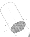
- a filter 10 includes a porous cellular body 14 comprising a first end 18 and a second end 22.
- the porous cellular body 14 comprises intersecting walls 38.
- the intersecting walls 38 can be thin and are porous and permeable.
- the walls 38 may have a thickness in mils (i.e., thousandths of 2.54 cm (an inch)) of from about 1 mil to about 15 mils, or from about 1 mil to about 14 mils, or from about 1 mil to about 13 mils, or from about 1 mil to about 12 mils, or from about 1 mil to about 11 mils, or from about 1 mil to about 10 mils, or from about 1 mil to about 9 mils, or from about 1 mil to about 8 mils, or from about 1 mil to about 7 mils, or from about 1 mil to about 6 mils, or from about 1 mil to about 5 mils, or from about 1 mil to about 4 mils, or from about 1 mil to about 3 mils, or from about 1 mil to about 2 mils, or any and all values and ranges therebetween.
- mils i.e., thousandths of 2.54 cm (an inch)
- the intersecting walls 38 extend across and between the first and second ends 18, 22 to form a large number of adjoining channels 26.
- the channels 26 extend between, and are open at, the first and second ends 18, 22 of the porous cellular body 14. According to various examples, the channels 26 are mutually parallel with one another. It will be understood that although the channels 26 are depicted with a generally square cross-sectional shape, the channels 26 may have a circular, triangular, rectangular, pentagonal, or higher order polygon cross-sectional shape without departing from the teachings provided herein.
- Each of the channels 26 has a hydraulic diameter d h .
- the hydraulic diameter d h is the width of the channel 26, i.e., the distance between the opposing walls 38.
- the hydraulic diameter d h is just that - the diameter of the channel 26.
- Adjacent channels 26 may have different hydraulic diameters d h .
- the channels 26 chosen to be plugged as described below will have approximately the same hydraulic diameter d h .
- the porous cellular body 14 may comprise a transverse cross-sectional channel density of from about 10 channels/in 2 (wherein/in 2 means /(2.54 cm)2) to about 900 channels/in 2 , or from about 100 channels/in 2 to about 900 channels/in 2 , or from about 20 channels/in 2 to about 800 channels/in 2 , or from about 30 channels/in 2 to about 700 channels/in 2 , or from about 40 channels/in 2 to about 600 channels/in 2 , or from about 50 channels/in 2 to about 500 channels/in 2 , or from about 60 channels/in 2 to about 400 channels/in 2 , or from about 70 channels/in 2 to about 300 channels/in 2 , or from about 80 channels/in 2 to about 200 channels/in 2 , or from about 90 channels/in 2 to about 100 channels/in 2 , or from about 100 channels/in 2 to about 200 channels/in 2 , or from about 200 channels/in 2 to about 300 channels/in 2 , or any and all values and ranges therebetween.
- the porous cellular body 14 may be formed of a variety of materials including ceramics, glass-ceramics, glasses, metals, and by a variety of methods depending upon the material selected. According to various examples, a green body which is transformed into the porous cellular body 14 may be initially fabricated from plastically formable and sinterable finely divided particles of substances that yield a porous material after being fired. Suitable materials for a green body which is formed into the porous cellular body 14 comprise metallics, ceramics, glass-ceramics, and other ceramic based mixtures. In some embodiments, the porous cellular body 14 is comprised of a cordierite (e.g., 2MgO ⁇ 2Al 2 O 3 ⁇ 5SiO 2 ) material.
- a cordierite e.g., 2MgO ⁇ 2Al 2 O 3 ⁇ 5SiO 2
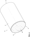
- the filter 10 further includes a plurality of plugs 30 positioned within at least some of the channels 26, in some embodiments at the first and second ends 18, 22, of the porous cellular body 14. For example, a portion of the plugs 30 close a first subset of channels 26 at the first end 18, and another portion of the plugs 30 close a second subset of channels 26 (different than the first subset of channels 26, such as in an alternating manner) at the second end 22 of the porous cellular body 14. As mentioned above, adjacent channels 26 may have a different hydraulic diameter d h , such that the channels 26 receiving the plugs 30 at the first end 18 have a smaller hydraulic diameter d h , and the channels 26 receiving the plugs 30 at the second end 22 have a larger hydraulic diameter d h . In such an arrangement, the first end 18 of the filter 10 is the fluid inlet, and the second end 22 of the filter 10 is the fluid outlet.
- the plugs 30 may have an axial length, or longest dimension extending substantially parallel with the channels 26, of about 0.5 mm or greater, of about 1 mm or greater, of about 1.5 mm or greater, of about 2 mm or greater, of about 2.5 mm or greater, of about 3 mm or greater, of about 3.5 mm or greater, of about 4 mm or greater, of about 4.5 mm or greater, of about 5 mm or greater, of about 5.5 mm or greater, of about 6.0 mm or greater, of about 6.5 mm or greater, of about 7.0 mm or greater, of about 7.5 mm or greater, of about 8.0 mm or greater, of about 8.5 mm or greater, of about 9.0 mm or greater, of about 9.5 mm or greater, of about 10.0 mm or greater, or about 15 mm or greater.
- the plugs 30 may have an axial length of from about 0.5 mm to about 10 mm, or from about 1 mm to about 9 mm, or from about 1 mm to about 8 mm, or from about 1 mm to about 7 mm, or from about 1 mm to about 6 mm, or from about 1 mm to about 5 mm, or from about 1 mm to about 4 mm, or from about 1 mm to about 3 mm, or from about 1 mm to about 2 mm, or any and all value and ranges therebetween.
- the plurality of plugs 30 located on the first end 18 of the body 14 may have a different length than the plugs 30 positioned on the second end 22 of the body 14.
- fluids such as gases carrying solid particulates are brought under pressure to the inlet face (e.g., the first end 18).
- the gases then enter the porous cellular body 14 via the channels 26 that are open (not plugged with one of the plugs 30) at the first end 18, pass through the intersecting walls 38 of the porous cellular body 14, and out the channels 26 which have an open end at the second end 22. Passing of the fluid through the walls 38 may allow the particulate matter in the fluid to remain trapped by the walls 38.
- the plugs 30 are positioned across the first and second ends 18, 22 of the porous cellular body 14 in a "checkerboard" pattern, but it will be understood that other patterns may also be applied. In the checkerboard pattern, each of an open channel's 26 nearest neighbor channels 26 on an end (e.g., either the first or second end 18, 22) includes a plug 30.
- the filter 10 may be formed using a mask layer 58 across the first end 18 of the porous cellular body 14 to cover a portion of the plurality of channels 26.
- the mask layer 58 may be comprised of a metal, a polymeric material, a composite material. and/or combinations thereof.
- the mask layer 58 may be comprised of a rice paper, cellophane, Plexiglas ® , biaxially-oriented polyethylene terephthalate, other materials, and/or combinations thereof.
- the mask layer 58 can be positioned on the first and/or second ends 18, 22 of the honeycomb body 14.
- the mask layer 58 may cover a portion, a majority, substantially all, or all of the first and/or second ends 18, 22.
- the mask layer 58 may have the same size and shape as the first and/or second ends 18, 22, or the size and/or shape of the mask layer 58 may be different.
- the mask layer 58 may have the same general shape as a cross-section of the porous cellular body 14 (e.g., generally circular) and may have a greater diameter than the porous cellular body 14 such that the mask layer 58 extends radially outwardly from the porous cellular body 14.
- the mask layer 58 may extend outwardly from the porous cellular body 14 about 0.5 cm or greater, about 1.0 cm or greater, about 1.5 cm or greater, about 2.0 cm or greater, about 2.5 cm or greater, about 3.0 cm or greater, about 3.5 cm or greater, about 4.0 cm or greater, about 4.5 cm or greater, about 5.0 cm or greater, about 5.5 cm or greater, about 6.0 cm or greater, or any and all values and ranges therebetween.
- the mask layer 58 may be coupled to the porous cellular body 14.
- the porous cellular body 14 and/or the mask layer 58 may have an adhesive adhered thereto, or disposed between, to allow sticking of the mask layer 58 to the porous cellular body 14.
- a band may be positioned around an exterior surface of the porous cellular body 14 to retain the mask layer 58 to the porous cellular body 14.
- the mask layer 58 may define a plurality of holes 66.
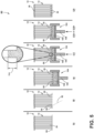
- FIG. 5 depicted is a schematic method 80 of plugging the porous cellular body 14 of the filter 10.
- the method 80 may begin with an optional preliminary step 84 of positioning the mask layer 58 over the porous cellular body 14 including the plurality of intersecting walls 38 that define at least one channel 26 between the intersecting walls 38.
- the mask layer 58 may be coupled to the porous cellular body 14 through the use of an adhesive to allow sticking of the mask layer 58 to the porous cellular body 14 and/or through the use of a band positioned around an exterior surface of the porous cellular body 14 to retain the mask layer 58 to the porous cellular body 14.
- the method 80 further includes, at step 88, a further optional preliminary step of perforating portions of the mask layer 58 that cover the channels 26 to be plugged with the plug 30 to form the holes 66 allowing access into those channels 26.
- Perforating the mask layer 58 to form the holes 66 in the mask layer 58 facilitates material transfer into the channel 26 from an environment on the other side of the mask layer 58.
- the hole 66 may be formed through mechanical force (e.g., with a punch) or by utilizing a laser 92.
- the mask layer 58 may include a plurality of holes 66 positioned across the mask layer 58.
- the holes 66 may be positioned in a pattern (e.g., a checkerboard-like pattern) across the mask layer 58. In checkerboard-like patterns, the holes 66 are positioned over every other channel 26 at a face (e.g., the first and/or second ends 18, 22). The result is a plurality of holes 66 through the mask layer 58 that are positioned over a plurality of the channels 26.
- the method 80 further includes, at step 96, contacting the porous cellular body 14 with a plugging mixture 100.
- step 96 the porous cellular body 14 and its plurality of channels 26 through the mask layer 58 is brought into contact within the plugging mixture 100.
- the porous cellular body 14 is coupled to a plugging system 104 including a plunger 108 to apply pressure to the plugging mixture 100.
- the mask layer 58 is disposed on at least one end of the porous cellular body 14. The end of the porous cellular body 14 with the mask layer 58 is positioned to contact the plugging mixture 100 such that the plugging mixture 100 may later flow through the holes 66 and into the channels 26.
- the plugging mixture 100 may be composed of an organic binder, an inorganic binder, water, and/or a plurality of inorganic particles.
- the plugging mixture 100 may include one or more additives (e.g., viscosity or rheology modifiers, plasticizers, organic binders, foaming agents, a pore former, etc.).
- the inorganic binder may take the form of silica, alumina, other inorganic binders, and combinations thereof.
- the silica may take the form of fine amorphous, nonporous, and generally spherical silica particles. At least one commercial example of suitable colloidal silica for the manufacture of the plugs 30 is produced under the name Ludox ® .
- the organic binder can be methylcellulose.
- the inorganic particles of the plugging mixture 100 may be comprised of glass material, ceramic material such as cordierite, mullite, silica, alumina, or aluminum titanate, glass-ceramic material, and/or combinations thereof.
- the inorganic particles may have the same or a similar composition to that of the green body that is used to produce the porous cellular body 14.
- the inorganic particles comprise cordierite or cordierite forming precursor materials which, upon reactive sintering or sintering, form a porous ceramic structure for the plugs 30.
- the inorganic particles may have a weight percentage in the plugging mixture 100 of from about 45% to about 80%, or from 50% to about 70%.
- the inorganic particles may have a weight percentage in the plugging mixture 100 of about 50%, about 52%, about 54%, about 56%, about 58%, about 60%, about 62%, about 62.5%, about 63%, about 64%, about 66%, about 68%, about 70%, or any and all values and ranges therebetween.
- the inorganic binder may have a weight percentage in the plugging mixture 100 of from about 10% to about 35%, or from about 10% to about 30%, or from about 10% to about 29%, or from about 10% to about 28%, or from about 10% to about 27%, or from about 10% to about 26%, or from about 10% to about 25%, or from about 10% to about 24%, or from about 10% to about 23%, or from about 10% to about 22%, or from about 10% to about 21%, or from about 10% to about 20%, or from about 10% to about 19%, or from about 10% to about 18%, or from about 10% to about 17%, or from about 10% to about 16%, or from about 10% to about 15%.
- a weight percentage in the plugging mixture 100 of from about 10% to about 35%, or from about 10% to about 30%, or from about 10% to about 29%, or from about 10% to about 28%, or from about 10% to about 27%, or from about 10% to about 26%, or from about 10% to about 25%, or from about 10% to about 24%, or from about 10% to
- the inorganic binder may have a weight percentage in the plugging mixture 100 of about 10%, about 11%, about 12%, about 13%, about 14%, about 15%, about 16%, about 17%, about 18%, about 19%, about 20%, about 21%, about 22%, about 23%, about 24%, about 25%, about 26%, about 27%, about 28%, about 29%, about 30%, about 31%, about 32%, about 33%, about 34%, about 35%, or any and all values and ranges therebetween.
- the plugging mixture 100 may have sufficient water that the plugging mixture 100 may be viscous or flow.
- the plugging mixture 100 may comprise a weight percentage of water from about 5% to about 40% water, or from about 10% to about 25%, or from about 10% to about 24%, or from about 10% to about 23%, or from about 10% to about 22%, or from about 10% to about 21%, or from about 10% to about 20%, or from about 10% to about 19%, or from about 10% to about 18%, or from about 10% to about 17%, or from about 10% to about 16%, or from about 10% to about 15%, or from about 10% to about 14%, or from about 10% to about 13%, or from about 10% to about 12%, or from about 10% to about 11%.
- the water may have a weight percentage in the plugging mixture 100 of about 10%, about 12%, about 14%, about 16%, about 18%, about 19%, about 20%, about 22%, about 24%, about 26%, about 28%, about 30%, about 31%, about 32%, about 33%, about 34%, about 35%, about 40%, or any and all values and ranges therebetween.
- the plugging mixture 100 may include one or more viscosity or rheology modifiers as additive(s).
- the plugging mixture 100 may include a polymer or a cellulose ether such as Methocel ® A4M.
- the plugging mixture 100 may have a weight percent of viscosity modifier of about 0.10%, or about 0.20%, about 0.30%, about 0.40%, about 0.50%, about 0.60%, about 0.70%, about 0.80%, about 0.90%, about 1.00%, about 1.1%, about 1.2%, about 1.3%, about 1.4%, about 1.5%, about 1.6%, about 1.7%, about 1.8%, about 1.9%, about 2.0%, about 2.1%, about 2.2%, about 2.3%, about 2.4%, about 2.5%, about 2.6%, about 2.7%, about 2.8%, about 2.9%, about 3.0%, about 3.1%, about 3.2%, about 3.3%, about 3.4%, about 3.5%, about 3.6%, about 3.7%, about 3.8%, or about 3.9% or about 4.0%, or any and all
- the volumetric solids loading within the plugging mixture 100 may be about 30%, or about 31%, or about 32%, or about 33%, or about 34%, or about 35%, or about 36%, or about 37%, or about 38%, or about 39%, or about 40%, or about 41%, or about 42%, or about 43%, or about 44%, or about 45%, or about 46%, or about 47%, or about 48%, or about 49%, or about 50%, or about 51%, or about 52%, or about 53%, or about 54%, or about 55%, or about 56%, or about 57%, or about 58%, or about 59%, or about 60%, or any and all values and ranges with any of the given values as end points.
- the volumetric solids loading within the water of the plugging mixture 100 may be from about 30% to about 60%, or from about 40% to about 50%, or from about 44% to about 47%, or from about 45% to about 47%, or from about 45.5% to about 46.7%.
- the method 80 further includes, at step 112, forcing the plugging mixture 100 into the plurality of channels 26 until a maximum, self-limiting, depth 114 of the plugging mixture 100 is disposed within the channels 26.
- the depth 114 is a maximum, self-limiting, depth to the extent that, once the depth 114 is achieved, additional force that the plunger 108 applies on the plugging mixture 100 will not result in the plugging mixture 100 extending further into the channels 26 than the depth 114.
- the depth 114 of the plugging mixture 100 being forced into the channels 26 is self-limiting because liquid of the plugging mixture 100 leaves the plugging mixture 100 and enters adjacent intersecting walls 38 of the permeable porous cellular body 14. As the fluid of the plugging mixture 100 passes into the intersecting walls 38, the solids of the plugging mixture 100 agglomerate and pack together. These solids resist further flow into the channel 26 and the maximum, self-limiting, depth 114 is thus achieved.
- the method 80 further includes either step 116a or step 116b.
- step 112 of forcing the plugging mixture 100 into the plurality of channels 26 until a maximum, self-limiting, depth 114 of the plugging mixture 100 is disposed within the channels 26 includes forcing the plugging mixture 100 into the plurality of channels 26 utilizing application of a constant pressure over time until the maximum, self-limiting, depth 114 of the plugging mixture 100 is disposed within the plurality of channels 26.
- the method 80 further includes, at step 116a, maintaining the constant pressure applied to the plugging mixture 100 until the flow of the plugging mixture 100 into the plurality of channels 26 decays from an initial flow rate to a predetermined flow rate.
- the method 80 further includes, at step 116b (instead of step 116a), maintaining a constant flow rate of the plugging mixture 100 into the channels 26 until a pressure on the plugging mixture 100 elevates to a predetermined pressure.
- step 116a or step 116b although the plugging mixture 100 cannot extend into the channels 26 beyond the depth 114, some plugging mixture 100 continues to enter the channels 26 to replace the liquid that left the previously injected plugging mixture 100 to enter the permeable porous intersecting walls 38.
- This additional plugging mixture 100 added during step 116a or step 116b, fills any voids and prevents any dimples from forming.
- step 116a the plunger 108 maintains a constant pressure on the plugging mixture 100 until a flow rate of the plugging mixture 100 decays to a predetermined (non-zero) flow rate.
- the constant pressure causes the plugging mixture 100 to flow into the channels 26 at an initial flow rate, which can already be in a state of decay.
- the constant pressure upon the plugging mixture 100 ceases.
- the flow rate of the plugging mixture 100 may be indirectly approximated by the displacement of the plunger 108. In other words, the rate of displacement of the plunger 108 is faster at the beginning of step 112 and lower near the end of step 116a. Accordingly, when the rate of displacement of the plunger 108 decays to below a predetermined rate of displacement, the constant pressure upon the plugging mixture 100 ceases.
- the constant pressure for step 116a is as constant as real-world conditions permit.
- the constant pressure can be about 0.007 MPa, about 0.03 MPa, about 0.07 MPa, about 0.10 MPa, or about 0.14 MPa, about 0.17 MPa, or about 0.21 MPa, or about 0.24 MPa, 0.28 MPa, or about 0.31 MPa, or about 0.34 MPa, or about 0.38 MPa, or about 0.41 MPa, or about 0.45 MPa, or about 0.48 MPa, or about 0.52 MPa, or about 0.55 MPa, or about 0.59 MPa, or about 0.62 MPa, or about 0.66 MPa, or about 0.69 MPa, or about 0.72 MPa, or about 0.76 MPa, or about 0.79 MPa, or about 0.83 MPa (about 1 psi, about 5 psi, about 10 psi, or about 15 psi, or about 20 psi, or about 25 psi, or about 30 psi, or about 35 psi
- Such ranges include a constant pressure of from about 0.007 MPa to about 0.34 MPa (about 1 psi to about 50 psi), including from about 0.10 MPa to about 0.28 MPa (about 15 psi to about 40 psi).
- the predetermined flow rate is 50% or less, or about 45% or less, or about 40% or less, or about 35% or less, or about 30% or less, or about 25% or less, or about 20% or less, or about 15% or less, or about 10% or less, or about 5% or less, or about 1%, or less than the initial flow rate. It will be understood that any and all values and ranges extending from any of the given values is contemplated.
- step 116b the plunger 108 maintains a constant flow rate of the plugging mixture 100 into the channels 26 until a pressure on the plugging mixture 100 elevates to a predetermined pressure.
- the constant flow rate of the plugging mixture 100 into the channels 26 begins during step 112 and, after the plugging mixture 100 achieves the self-limiting, maximum depth 114 and resists further flow of plugging mixture 100 into the channels 26, the pressure on the plugging mixture 100 must rise to maintain the constant flow rate.
- the pressure elevates to the predetermined pressure and the plugging operation ceases.
- the flow rate of the plugging mixture 100 may be indirectly approximated by the displacement of the plunger 108.
- the predetermined pressure may be about 0.007 MPa, or about 0.03 MPa, or about 0.07 MPa, or about 0.10 MPa, or about 0.14 MPa, about 0.17 MPa, or about 0.21 MPa, or about 0.24 MPa, 0.28 MPa, or about 0.31 MPa, or about 0.34 MPa, or about 0.38 MPa, or about 0.41 MPa, or about 0.45 MPa, or about 0.48 MPa, or about 0.52 MPa, or about 0.55 MPa, or about 0.59 MPa, or about 0.62 MPa, or about 0.66 MPa, or about 0.69 MPa, or about 0.72 MPa, or about 0.76 MPa, or about 0.79 MPa, or about 0.83 MPa (about 5 psi, or about 10 psi, or about 15 psi, or about 20 psi, or about 25 psi, or about 30 psi, or about 35 psi, or about 40 psi, or about 45 psi, or about 50 p
- the method 80 further includes, at step 120, heating the plugging mixture 100 to form the plugs 30 within the channels 26. Once the porous cellular body 14 is disengaged from the plugging mixture 100, the mask layer 58 may be removed. The porous cellular body 14 is then heated to sinter the plugging mixture 100 and thus form the plurality of plugs 30.
- the time and temperature of step 120 may vary depending on the composition of the plugging mixture 100 as well as other factors. In general however, sintering of the plugging mixture 100 to form the plurality of plugs 30 occurs at a temperature of from about 800 °C to about 1500 °C.
- sintering of the plugging mixture 100 can occur at about 800 °C, about 900 °C, about 1,000 °C, about 1,100 °C, about 1,200 °C, about 1,300 °C, about 1,400 °C, about 1,500 °C, or any and all values and ranges therebetween. Sintering of the plugging mixture 100 can result in the plugs 30 having a length that is equal to or less than the maximum, self-limiting, depth 114 of the plugging mixture 100 forced into the channels 26.
- step 120 of heating of the porous cellular body 14 further includes, before heating the plugging mixture 100 in the permeable porous cellular body 14 to form a plurality of plugs, heating the plugging mixture 100 in the permeable porous cellular body 14: (a) to dry the plugging mixture 100 (drying the plugging mixture 100 sets the plugging mixture 100 within the channels 26); or (b) to remove organic binder (calcining) from the plugging mixture 100; or (c) both (a) and (b).
- calcining of the porous cellular body 14 occurs at a temperature of from about 350 °C to about 600 °C.
- calcining can occur at about 350 °C, about 400 °C, about 450 °C, about 500 °C, about 550 °C, about 600 °C, or any and all values and ranges therebetween.
- a volume of the plugging mixture 100 insufficient to achieve the maximum, self-limiting, depth 114 was utilized.
- prior methods of forming the plugs 30 of the filter 10 utilized a fixed volume of the plugging mixture 100 to achieve a certain target depth 114 into the channels 26 that was less than the maximum, self-limiting, depth 114.
- the absorption of liquid from the plugging mixture 100 into the intersecting walls 38 left voids and dimples after the plugging mixture 100 was formed into the plugs 30.
- the method 80 of the present disclosure is advantageous over the prior methods.
- the maximum, self-limiting, depth 114 still provides a certain consistent depth 114 across the channels 26.
- the method 80 results in plugs 30 that are substantially free of dimples and voids.
- the plugging mixture 100 replaces liquid that the intersecting walls 38 withdraws from the plugging mixture 100 and forces out gas present in the plugging mixture 100 within the channels 26, so as to prevent the formation of, or eliminate, voids within the plugging mixture 100 disposed within the channels 26.
- the maximum, self-limiting, depth 114 is a function of a variety of variables. Adjusting these variables above alters the maximum, self-limiting, depth 114, and thus the depth 114 is just as tunable as with prior methods.
- the maximum, self-limiting, depth 114 is a function of the level of constant pressure applied to the plugging mixture 100 during step 116a of the method 80 above, and the level of the constant flow rate at which the plugging mixture 100 is forced into the plurality of channels 26 during step 116b of the method 80 above. For example, increasing the constant pressure or increasing the constant flow rate at steps 116a, 116b respectively increases the maximum, self-limiting, depth 114. In contrast, decreasing the constant pressure or decreasing the constant flow rate at steps 116a, 116b respectively decreases the maximum, self-limiting, depth 114.
- the maximum, self-limiting, depth 114 is a function of the hydraulic diameter d h of the plurality of channels 26 of the porous cellular body 14 into which the plugging mixture 100 is forced to form the plugs 30. For example, increasing the hydraulic diameter d h increases the maximum, self-limiting, depth 114. In contrast, decreasing the hydraulic diameter d h decreases the maximum, self-limiting, depth 114.
- the maximum, self-limiting, depth 114 is additionally a function of absorptive capacity of the porous cellular body 14. For example, presoaking the porous cellular body 14 in a liquid (e.g., water) decreases the ability of the intersecting walls 38 to absorb the liquid of the plugging mixture 100 and, thus, increases the maximum, self-limiting, depth 114. In another example, contacting the channels 26 of the porous cellular body 14 at the first and/or second ends 18, 22 with a hydrophobic coating (such as by immersion or spraying) inhibits capillary action that draws fluid from the plugging mixture 100 into the intersecting walls 38 of the channels 26, and thus increases the maximum, self-limiting, depth 114. Stated another way, the hydrophobic coating decreases the rate of viscosity change of the plugging mixture 100 as the plugging mixture 100 flows into the channels 26 and the intersecting walls 38 absorb liquid from the plugging mixture 100.
- a hydrophobic coating such as by immersion or spraying
- the maximum, self-limiting, depth 114 is additionally a function of the permeability of the inorganic particles of the plugging mixture 100. For example, decreasing the permeability of the inorganic particles of the plugging mixture 100 increases the maximum, self-limiting, depth 114. In turn, decreasing the average particle size of the inorganic particles with a fixed particle size distribution breadth, or broadening the particle size distribution of the inorganic particles at the same average particle size, decreases the permeability of the inorganic particles of the plugging mixture 100. In contrast, increasing the permeability of the inorganic particles of the plugging mixture 100 decreases the maximum, self-limiting, depth 114.
- These changes can be accomplished through changes to a single inorganic material or through the blending of two separate inorganic materials that have different average particle size and/or different particle size distribution breadths.
- the shape of the inorganic particles additionally can affect the permeability of the inorganic particles.
- the maximum, self-limiting, depth 114 is additionally a function of the viscosity of the liquid of the plugging mixture 100. For example, increasing the viscosity of the liquid in the plugging mixture 100 at a fixed viscosity of the plugging mixture 100 increases the maximum, self-limiting, depth 114. This can be achieved by increasing the concentration of polymer (organic binder) within the plugging mixture 100 and decreasing the volumetric solids loading. In contrast, decreasing the viscosity of the liquid in the plugging mixture 100 at a fixed viscosity of the plugging mixture 100 decreases the maximum, self-limiting, depth 114. This can be achieved by decreasing the concentration of polymer (organic binder) within the plugging mixture 100 and increasing the volumetric solids loading.
- the maximum, self-limiting, depth 114 is additionally a function of the viscosity of the plugging mixture 100 as a whole. For example, lowering the viscosity of the plugging mixture 100 at a fixed liquid viscosity increases the maximum, self-limiting, depth 114. In turn, decreasing the volumetric solids loading lowers the viscosity of the plugging mixture 100 at a fixed liquid viscosity. In contrast, increasing the viscosity of the plugging mixture 100 at a fixed liquid viscosity decreases the maximum, self-limiting, depth 114. For example, increasing the volumetric solids loading increases the viscosity of the plugging mixture 100 at a fixed liquid viscosity.
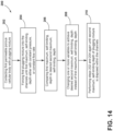
- the method 200 comprises contacting a permeable porous cellular body 14 with a plugging mixture 100.
- the permeable porous cellular body 14 defines a plurality of channels 26, as explained above.
- the method 200 at step 204, further comprises either performing step 116a or step 116b of the method 80 described above.
- the method 200 at step 204 further comprises either (i) forcing the plugging mixture 100 into the plurality of channels 26 at a first constant flow rate until a first maximum, self-limiting, depth 114 of the plugging mixture 100 is disposed within the plurality of channels 26, and maintaining the first constant flow rate of the plugging mixture 100 into the plurality of channels 26 until a pressure on the plugging mixture 100 elevates to a predetermined pressure, or (ii) forcing the plugging mixture 100 into the plurality of channels 26 at a first constant pressure until a first maximum, self-limiting, depth of plugging mixture 100 is disposed within the plurality of channels 26 and maintaining the first constant pressure applied to the plugging mixture 100 until flow of the plugging mixture 100 into the plurality of channels 26 decays from an initial flow rate to a predetermined flow rate.
- step 204 results in the plugging mixture 100 extending into the channels 26 to a first maximum, self-
- the method 200 at step 206, further comprises comparing the first maximum, self-limiting, depth 114 to a desired second maximum, self-limiting, depth 114'.
- the first maximum, self-limiting, depth 114 may be deeper or shallower than the desired maximum, self-limiting, depth 114.
- step 208 further comprises changing one or more of the variables described above so that the desired second maximum, self-limiting, depth 114' can be achieved instead of the first maximum, self-limiting, depth 114.
- step 208 includes changing one or more of the following: (i) the first constant pressure to a second constant pressure; (ii) the first constant flow rate to a second constant flow rate; (iii) a first hydraulic diameter d h of the plurality of channels 26 to a second hydraulic diameter d h ; (iv) a first absorptive capacity of the porous cellular body 14 to a second absorptive capacity; (v) a first permeability of inorganic particles within the plugging mixture 100 to a second permeability; (vi) a first viscosity of liquid in the plugging mixture 100 to a second viscosity while maintaining approximately the same overall viscosity of the plugging mixture 100; (vii) a first viscosity of the plugging mixture 100 to a second
- the method 200 at step 210, further comprises performing steps 202 and 204 again until the second maximum, self-limiting depth 114' of the plugging mixture 100 is disposed within the plurality of channels 26.
- the second maximum, self-limiting, depth 114' of the plugging mixture 100 is deeper than the first maximum, self-limiting, depth 114'.
- the second constant pressure is higher than the first constant pressure that resulted in the first maximum, self-limiting, depth 114'.
- the second constant flow rate is greater than the first constant flow rate that resulted in the first maximum, self-limiting, depth 114'.
- the second hydraulic diameter d h is wider than the first hydraulic diameter d h that resulted in the first maximum, self-limiting, depth 114'.
- a different permeable porous cellular body 14' with channels 26' having a wider hydraulic diameter d h can be chosen.
- the second absorptive capacity of the porous cellular body 14' is less than the first absorptive capacity that resulted in the first maximum, self-limiting, depth 114.
- the channels 26' of the porous cellular body 14' chosen to receive the plugging mixture 100 in the subsequent iteration of steps 202 and 204 can be contacted with water (such as by soaking the porous cellular body 14' in water) or coated with a hydrophobic coating, as mentioned above.
- the second permeability of inorganic particles within the plugging mixture 100 is less than the first permeability that resulted in the first maximum, self-limiting, depth 114'.
- a different plugging mixture 100' can be utilized for the subsequent iteration of steps 202 and 204 that has a smaller average particle size of the inorganic particles with a fixed particle size distribution breadth, or a broader particle size distribution of the inorganic particles at the same average particle size.
- the second viscosity of the liquid in the plugging mixture 100 ' is greater than the first viscosity of the liquid in the plugging mixture 100 that resulted in the first maximum, self-limiting, depth 114, while maintaining approximately the same overall viscosity of the plugging mixture 100' as plugging mixture 100.
- a different plugging mixture 100' can be utilized for the subsequent iteration of steps 202 and 204 that has a greater amount of dissolved polymer in the water than the plugging mixture 100 that resulted in the first maximum, self-limiting, depth 114.
- the volumetric solids loading in the plugging mixture 100' can be reduced compared to the plugging mixture 100 in an attempt to maintain approximately the same overall viscosity for the plugging mixture 100'.
- the second viscosity of the plugging mixture 100' is less than the first viscosity of the plugging mixture 100 that resulted in the first maximum, self-limiting, depth 114 while maintaining approximately the same viscosity for the liquid of the plugging mixture 100' as for the plugging mixture 100.
- a different plugging mixture 100' can be utilized for the subsequent iteration of steps 202 and 204 that has less volumetric solids loading but the same liquid composition as the plugging mixture 100 that resulted in the first, maximum, self-limiting depth 114.
- the second maximum, self-limiting, depth 114' of the plugging mixture 100' is shallower than the first maximum, self-limiting, depth 114.
- the second constant pressure is lower than the first constant pressure that resulted in the first maximum, self-limiting, depth 114.
- the second constant flow rate is less than the first constant flow rate that resulted in the first maximum, self-limiting, depth 114.
- the second hydraulic diameter d h is narrower than the first hydraulic diameter d h that resulted in the first maximum, self-limiting, depth 114.
- a different permeable porous cellular body 14' with channels 26' having a narrower hydraulic diameter d h can be chosen.
- the second absorptive capacity of the porous cellular body 14' is greater than the first absorptive capacity that resulted in the first maximum, self-limiting, depth 114.
- the porous cellular body 14' utilized for the subsequent iteration of steps 202 and 204 does not include such a hydrophobic coating.
- the second permeability of inorganic particles within the plugging mixture 100' is greater than the first permeability of the inorganic particles within the plugging mixture 100 that resulted in the first maximum, self-limiting, depth 114.
- a different plugging mixture 100' can be utilized for the subsequent iteration of steps 202 and 204 that has a larger average particle size of the inorganic particles with a fixed particle size distribution breadth, or a narrower particle size distribution of the inorganic particles at the same average particle size.
- the second viscosity of the liquid in the plugging mixture 100' is less than the first viscosity of the liquid in the plugging mixture 100 that resulted in the first maximum, self-limiting, depth 114, while maintaining approximately the same overall viscosity of the plugging mixture 100' compared to the plugging mixture 100.
- a different plugging mixture 100' can be utilized for the subsequent iteration of steps 202 and 204 that has a lesser amount of dissolved polymer in the water than the plugging mixture 100 that resulted in the first maximum, self-limiting, depth 114.
- the volumetric solids loading in the plugging mixture 100' can be increased compared to the plugging mixture 100 in an attempt to maintain approximately the same overall viscosity for the plugging mixture 100' compared to the plugging mixture 100.
- the second viscosity of the plugging mixture 100' is greater than the first viscosity of the plugging mixture 100 that resulted in the first maximum, self-limiting, depth 114 while maintaining approximately the same viscosity for the liquid of the plugging mixture 100' as the liquid of the plugging mixture 100.
- a different plugging mixture 100' can be utilized for the subsequent iteration of steps 202 and 204 that has greater volumetric solids loading but the same liquid composition as the plugging mixture 100 that resulted in the first, maximum, self-limiting depth 114.
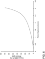
- FIG. 6 provided is a graph of pressure (e.g., plugging pressure) generated as a function of piston (e.g., the plunger 108) displacement, specifically a piston displacing the plugging mixture 100 into the channels 26 of the porous cellular body 14.
- the piston displacement is a proxy for the volumetric flow of the plugging mixture 100 into the channels 26.
- the porous cellular body 14 for this graph had 31 channels 26 per cm 2 (200 channels 26 per square inch) with 10.02 cm (0.008 inch) thick intersecting walls 38.
- the pressure required to push more of the plugging mixture 100 into the porous cellular body 14 increases.
- the required pressure increases in a relatively linear manner (e.g., displacement of from about 0 mm to about 2.5 mm) and then began approaching an asymptote (e.g., the maximum achievable depth) where increases in the piston displacement require larger and larger pressure increases.
- the asymptotic nature of the pressure-displacement curve is due to the removal of liquid from the plugging mixture 100 and the consolidation of the solids of the plugging mixture 100.
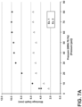
- FIG. 7A therein presented is a graph of the depth 114 of the plugging mixture 100 during the method 80 as a function of plugging pressure where step 116b of the method 80 was utilized and a constant flow rate of the plugging mixture 100 into the channels 26 was maintained.
- the results for two different porous cellular bodies 14 are presented.
- the reference to “Ex. 1” refers to a porous cellular body 14 with 31 channels 26 per cm 2 (200 channels 26 per square inch), and 0.02 cm (0.008 inch) thick intersecting walls 38.
- the reference to “Ex. 2” refers to a porous cellular body 14 with 46.5 channels per cm 2 (300 channels 26 per square inch), and 0.02 cm (0.008 inch) thick intersecting walls 38.
- the method 80 can cease at a predetermined pressure of, for example, 0.34 MPa (50 psi), which results in elimination of voids and dimples.
- a predetermined pressure of, for example, 0.34 MPa (50 psi) which results in elimination of voids and dimples.
- the constant flow rate of the plugging mixture 100 causes the plugging mixture 100 to reach a maximum, self-limiting, depth 114 of just over 5 mm
- maintaining the constant flow rate only results in the pressure on the plugging mixture 100 elevating from about 0.14 MPa to 0.55 MPa (about 20 psi to 80 psi).
- the method 80 can cease at a predetermined pressure of, for example, 0.28 MPa (40 psi), which results in elimination of voids and dimples.
- FIG. 7B therein presented is a graph of pressure applied to the plugging mixture 100 and the plunger 108 displacement rate as a function of time during the method 80 where step 116a of the method 80 was utilized and a constant pressure applied to the plugging mixture 100 was maintained.
- the displacement rate of the plunger 108 (approximates the flow rate of the plugging mixture 100 into the channels 26) decays.
- the constant pressure (of approximately 0.10 MPa (15 psi)) can cease.
- the plugging mixture 100 will have reached the maximum, self-limiting, depth 114 and the continued flow of the plugging mixture 100 while the displacement rate (flow rate) decays eliminates voids and dimples in the plugging mixture 100.
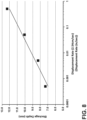
- FIG. 8 therein presented is a graph of maximum, self-limiting, depth 114 for a plugging mixture 100 as a function of plugging rate (plunger 108 displacement rate, which approximates flow rate of the plugging mixture 100 into the channels 26).
- plugging rate plugging rate
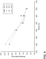
- FIG. 9 therein presented is a graph of the maximum, self-limiting, depth 114 as a function of the volume percentage of solids in the plugging mixture 100 and the concentration of a water soluble polymer present in the plugging mixture 100 relative to water to modify the viscosity. More specifically, Examples 3-6 (“Ex. 3" and so on) utilize progressively decreasing concentrations of a water soluble polymer (organic binder) present relative to water in the plugging mixture 100 to decrease the viscosity of the liquid in the plugging mixture 100.
- Example 3 includes 2.9 wt% of Methocel ® A4M
- Example 4 includes 2.7 wt% of Methocel ® A4M
- Example 5 includes 2.5 wt% of Methocel ® A4M
- Example 6 includes 2.3 wt% of Methocel ® A4M.
- each particular example includes data points measuring the maximum, self-limiting, depth 114 for progressively increasing volume percentage of solids in the plugging mixture 100 (from left to right along the x-axis), which increases the viscosity of the plugging mixture 100 as a whole.
- the graph illustrates several things. Among other things, the graph illustrates that increasing the concentration of the water soluble polymer (e.g., Example 4 included more Methocel ® than Example 5), which increases the viscosity of the liquid in the plugging mixture 100, causes an increase in the maximum, self-limiting, depth 114, for any particular fixed volumetric solids loading in the plugging mixture 100. As the viscosity of the liquid in the plugging mixture 100 increases, it becomes harder for the liquid in the plugging mixture 100 to leave the plugging mixture 100 and enter the intersecting walls 38.
- the water soluble polymer e.g., Example 4 included more Methocel ® than Example 5
- the graph illustrates that lowering the volumetric solids loading of the plugging mixture 100 at fixed liquid viscosity (which lowers the viscosity of the plugging mixture 100) increases the maximum, self-limiting, depth 114.
- the percent volume of solids is decreased for any particular example, including the same amount of water soluble polymer, the maximum, self-limiting, depth 114 increases.
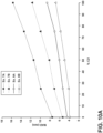
- FIG. 10A therein presented is a graph of the maximum, self-limiting, depth 114 as a function of (a) particle size distribution of the solids in the plugging mixture 100, (b) the viscosity of the plugging mixture 100, and (c) location of the plugging mixture 100 as inlet versus outlet, i.e., first end 18 or second end 22 as described above.
- FIG. 10B illustrates particle size distribution and average particle size for two different solids - EJ101 (having an average particle size of 37 ⁇ m) and C-21 Grog (having an average particle size of 26 ⁇ m).
- decreasing the average particle size of the inorganic particles with a fixed particle size distribution breadth decreases the permeability of liquid through the inorganic particles of the plugging mixture 100, due to the increasing concentration of finer inorganic particles in a mixture of two inorganic materials, which increases the maximum, self-limiting, depth 114.
- the percent "C21 Grog" increases for any given example, thus decreasing the average particle size of the inorganic particles within the plugging mixture 100, the maximum, self-limiting, depth 114 increases.
- Example 7A and 7B both measured at the outlet (second end 22), varied in the viscosity of the plugging mixture 100 - Example 7A had a lower viscosity (0.3) than Example 7B (0.7) as measured using a ball push test, a difference in water content causing the difference in viscosity (Example 7A had more water). Because Example 7A had a lower viscosity than Example 7B, Example 7A provided a higher maximum, self-limiting, depth 114.
- the channels 26 at the inlet (first end 18) into which the plugging mixture 100 is inserted are narrower than the channels 26 at the outlet (second end 22) into which the plugging mixture 100 is inserted.
- Examples 7A and 8A are the same plugging mixture 100, just inserted into the outlet (second end 22) and inlet (first end 18) respectively.
- Examples 7B and 8B are the same plugging mixture 100, just inserted into the outlet (second end 22) and inlet (first end 18) respectively.
- Example 7A versus Example 8A, and Example 7B versus Example 8B demonstrates, the larger the channels 26 into which the plugging mixture 100 is inserted, the greater the maximum, self-limiting, depth 114.
- the smaller channels 26 at the inlet (first end 18) than the outlet (second end 22) cause a higher pressure upon the plugging mixture 100, resulting in a faster flow of liquid from the plugging mixture 100 into the intersecting walls 38, resulting in a smaller maximum, self-limiting, depth 114 at the channels 26 of the inlet (first end 18).
- FIG. 11 therein presented is a graph of the maximum, self-limiting, depth 114 as a function of the gas permeability of the inorganic particles of the plugging mixture 100.
- decreasing the permeability of the inorganic particles of the plugging mixture 100 increases the maximum, self-limiting, depth 114.
- liquid can more easily exit the plugging mixture 100, thus decreasing the maximum, self-limiting, depth 114.
- the opposite is true as well.
- the graph shows this - small decreases of the permeability of the inorganic particles at low permeability (e.g., less than 15 * 10 9 cm 2 ) provides relatively large increases in the maximum, self-limiting, depth 114.
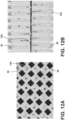
- FIGS. 12A-13B therein presented are images of the plugs 30.
- the plugs 30 of FIGS. 12A and 12B were prepared via prior methods that did not utilize the maximum, self-limiting, depth 114 and thus show dimples 122 and voids 124.
- the plugs 30 of FIGS. 12A-13B were prepared via prior methods that did not utilize the maximum, self-limiting, depth 114 and thus show dimples 122 and voids 124.
- 13A and 13B were prepared via the method 80 of the present disclosure that does utilize the maximum, self-limiting, depth 114 and either: (a) maintains a constant pressure (via the plunger 108 or otherwise) on the plugging mixture 100 until a flow rate of the plugging mixture 100 decays to a predetermined (non-zero) flow rate at step 116a; or (b) maintains a constant flow rate of the plugging mixture 100 into the channels 26 until a pressure on the plugging mixture 100 elevates to a predetermined pressure at step 116b.
- the results are the plugs 30 without dimples 122 or voids 124. The absence of the dimples 122 and voids 124 is due to the consolidation of the plugging mixture 100.
Landscapes
- Engineering & Computer Science (AREA)
- Chemical & Material Sciences (AREA)
- Structural Engineering (AREA)
- Ceramic Engineering (AREA)
- Mechanical Engineering (AREA)
- Chemical Kinetics & Catalysis (AREA)
- Filtering Materials (AREA)
Applications Claiming Priority (2)
| Application Number | Priority Date | Filing Date | Title |
|---|---|---|---|
| US201862783679P | 2018-12-21 | 2018-12-21 | |
| PCT/US2019/066462 WO2020131668A1 (en) | 2018-12-21 | 2019-12-16 | Methods of plugging a permeable porous cellular body |
Publications (2)
| Publication Number | Publication Date |
|---|---|
| EP3898148A1 EP3898148A1 (en) | 2021-10-27 |
| EP3898148B1 true EP3898148B1 (en) | 2023-05-24 |
Family
ID=69160437
Family Applications (1)
| Application Number | Title | Priority Date | Filing Date |
|---|---|---|---|
| EP19836419.2A Active EP3898148B1 (en) | 2018-12-21 | 2019-12-16 | Methods of plugging a permeable porous cellular body |
Country Status (5)
| Country | Link |
|---|---|
| US (2) | US12103195B2 (pl) |
| EP (1) | EP3898148B1 (pl) |
| CN (1) | CN113498372B (pl) |
| PL (1) | PL3898148T3 (pl) |
| WO (1) | WO2020131668A1 (pl) |
Family Cites Families (17)
| Publication number | Priority date | Publication date | Assignee | Title |
|---|---|---|---|---|
| US4455180A (en) | 1981-08-24 | 1984-06-19 | Corning Glass Works | Method of fabricating a sintered and selectively plugged honeycomb structure |
| US4432918A (en) | 1981-08-24 | 1984-02-21 | Corning Glass Works | Methods for fabricating selectively plugged honeycomb structures |
| WO2002085482A2 (en) * | 2001-04-23 | 2002-10-31 | Dow Global Technologies Inc. | Method of making wall-flow monolith filter |
| WO2003067041A1 (en) * | 2002-02-05 | 2003-08-14 | Ibiden Co., Ltd. | Honeycomb filter for exhaust gas decontamination, adhesive, coating material and process for producing honeycomb filter for exhaust gas decontamination |
| JP4437084B2 (ja) * | 2002-10-07 | 2010-03-24 | イビデン株式会社 | ハニカム構造体 |
| US20050103232A1 (en) * | 2003-11-19 | 2005-05-19 | Gadkaree Kishor P. | Composition and method for making ceramic filters |
| US7897099B2 (en) | 2004-01-13 | 2011-03-01 | Ngk Insulators, Ltd. | Method for producing honeycomb structure |
| US7922951B2 (en) * | 2004-12-21 | 2011-04-12 | Corning Incorporated | Plugging methods and apparatus for particulate filters |
| EP1911570B1 (en) * | 2004-12-21 | 2009-05-20 | Corning Incorporated | Plugging method and apparatus for particulate filters |
| EP1964656A3 (de) * | 2007-03-01 | 2011-03-30 | Maschinenbau Gerold Gmbh + Co. Kg | Vorrichtung und Verfahren zum Einbringen eines pastösen Materials in einen Wabenkörper |
| US7722791B2 (en) | 2007-07-18 | 2010-05-25 | Ngk Insulators, Ltd. | Method for manufacturing honeycomb structure and manufacturing apparatus thereof |
| US8808601B2 (en) | 2008-05-30 | 2014-08-19 | Corning Incorporated | Method for manufacturing ceramic filter |
| EP2537654B1 (en) * | 2010-03-30 | 2015-03-18 | Sumitomo Chemical Company Limited | Method for manufacturing a honeycomb-structured object |
| US8609032B2 (en) * | 2010-11-29 | 2013-12-17 | Corning Incorporated | Porous ceramic honeycomb articles and methods for making the same |
| US8609002B2 (en) * | 2011-03-31 | 2013-12-17 | Corning Incorporated | Method of plugging a honeycomb body |
| JP6232060B2 (ja) * | 2012-06-27 | 2017-11-15 | ダウ グローバル テクノロジーズ エルエルシー | セラミックハニカムフィルター中に多孔質プラグを作製する改良された方法 |
| US20230110252A1 (en) * | 2021-10-07 | 2023-04-13 | Corning Incorporated | Honeycomb plugging apparatus and methods providing reduced slump |
-
2019
- 2019-12-16 PL PL19836419.2T patent/PL3898148T3/pl unknown
- 2019-12-16 US US17/415,172 patent/US12103195B2/en active Active
- 2019-12-16 CN CN201980092753.0A patent/CN113498372B/zh active Active
- 2019-12-16 WO PCT/US2019/066462 patent/WO2020131668A1/en not_active Ceased
- 2019-12-16 EP EP19836419.2A patent/EP3898148B1/en active Active
-
2024
- 2024-09-04 US US18/823,906 patent/US20240424712A1/en active Pending
Also Published As
| Publication number | Publication date |
|---|---|
| CN113498372A (zh) | 2021-10-12 |
| EP3898148A1 (en) | 2021-10-27 |
| US12103195B2 (en) | 2024-10-01 |
| US20240424712A1 (en) | 2024-12-26 |
| PL3898148T3 (pl) | 2023-10-02 |
| WO2020131668A1 (en) | 2020-06-25 |
| US20220063129A1 (en) | 2022-03-03 |
| CN113498372B (zh) | 2023-05-02 |
Similar Documents
| Publication | Publication Date | Title |
|---|---|---|
| JP4136490B2 (ja) | ハニカム構造体の製造方法 | |
| EP1724448B2 (en) | Honeycomb filter for purifyng exhaust gases, adhesive, coating material, and manufacturing method of honeycomb filter for purifying exhaust gases | |
| EP2412420B1 (en) | Honeycomb filter and method for producing honeycomb filter | |
| EP2241362A1 (en) | Partially seal-less dpf | |
| CN101541710B (zh) | 耐用的蜂窝体结构 | |
| EP1607130A1 (en) | Sealed honeycomb structure and method of producing the same | |
| DE69604867T2 (de) | Verfahren zum Verschliessen der Endfläche einer keramischen Wabenstruktur | |
| EP3898148B1 (en) | Methods of plugging a permeable porous cellular body | |
| US20150121827A1 (en) | Method of making porous plugs in ceramic honeycomb filter | |
| KR100791875B1 (ko) | 세라믹 하니컴 구조체의 제조 방법 | |
| JP2009006629A (ja) | ハニカム構造体の目封止装置 | |
| EP2174698A1 (en) | Honeycomb Structure | |
| CN113457314A (zh) | 蜂窝过滤器 | |
| EP2098348A1 (en) | Process for producing plugged honeycomb structure | |
| WO2007078732A2 (en) | Honeycomb filters with reduced number of unplugged partial peripheral cells and methods of manufacturing same | |
| EP3189019B1 (en) | Honeycomb body having layered plugs and method of making the same | |
| WO2004047958A2 (de) | Katalysator und verfahren zur beschichtung eines katalysatorträgers enthaltend zwei unterschiedliche teilstrukturen mit einer katalytisch aktiven beschichtung | |
| CN112437763A (zh) | 具有高强度表皮的陶瓷蜂窝体及其制造方法 | |
| US20240359359A1 (en) | Methods of plugging a honeycomb body and mask layers thereof | |
| DE102006000067A1 (de) | Keramischer Wabenstrukturkörper und sein Herstellungsverfahren | |
| CN118751084B (zh) | 一种双层多孔陶瓷板及其制备方法和应用 | |
| EP3887019B1 (en) | Methods of making plugged honeycomb bodies with cement patties | |
| DE102007028495A1 (de) | Verfahren zur Herstellung eines porösen Substrates | |
| CN101240727A (zh) | 陶瓷蜂窝式过滤器 | |
| JP2014000783A (ja) | ハニカム構造体の製造方法並びにハニカム構造体及び固液分離用フィルタ |
Legal Events
| Date | Code | Title | Description |
|---|---|---|---|
| STAA | Information on the status of an ep patent application or granted ep patent |
Free format text: STATUS: UNKNOWN |
|
| STAA | Information on the status of an ep patent application or granted ep patent |
Free format text: STATUS: THE INTERNATIONAL PUBLICATION HAS BEEN MADE |
|
| PUAI | Public reference made under article 153(3) epc to a published international application that has entered the european phase |
Free format text: ORIGINAL CODE: 0009012 |
|
| STAA | Information on the status of an ep patent application or granted ep patent |
Free format text: STATUS: REQUEST FOR EXAMINATION WAS MADE |
|
| 17P | Request for examination filed |
Effective date: 20210707 |
|
| AK | Designated contracting states |
Kind code of ref document: A1 Designated state(s): AL AT BE BG CH CY CZ DE DK EE ES FI FR GB GR HR HU IE IS IT LI LT LU LV MC MK MT NL NO PL PT RO RS SE SI SK SM TR |
|
| DAV | Request for validation of the european patent (deleted) | ||
| DAX | Request for extension of the european patent (deleted) | ||
| GRAP | Despatch of communication of intention to grant a patent |
Free format text: ORIGINAL CODE: EPIDOSNIGR1 |
|
| STAA | Information on the status of an ep patent application or granted ep patent |
Free format text: STATUS: GRANT OF PATENT IS INTENDED |
|
| INTG | Intention to grant announced |
Effective date: 20221219 |
|
| GRAS | Grant fee paid |
Free format text: ORIGINAL CODE: EPIDOSNIGR3 |
|
| GRAA | (expected) grant |
Free format text: ORIGINAL CODE: 0009210 |
|
| STAA | Information on the status of an ep patent application or granted ep patent |
Free format text: STATUS: THE PATENT HAS BEEN GRANTED |
|
| AK | Designated contracting states |
Kind code of ref document: B1 Designated state(s): AL AT BE BG CH CY CZ DE DK EE ES FI FR GB GR HR HU IE IS IT LI LT LU LV MC MK MT NL NO PL PT RO RS SE SI SK SM TR |
|
| REG | Reference to a national code |
Ref country code: GB Ref legal event code: FG4D |
|
| REG | Reference to a national code |
Ref country code: CH Ref legal event code: EP |
|
| REG | Reference to a national code |
Ref country code: DE Ref legal event code: R096 Ref document number: 602019029371 Country of ref document: DE |
|
| REG | Reference to a national code |
Ref country code: AT Ref legal event code: REF Ref document number: 1569255 Country of ref document: AT Kind code of ref document: T Effective date: 20230615 |
|
| REG | Reference to a national code |
Ref country code: IE Ref legal event code: FG4D |
|
| P01 | Opt-out of the competence of the unified patent court (upc) registered |
Effective date: 20230705 |
|
| REG | Reference to a national code |
Ref country code: LT Ref legal event code: MG9D |
|
| REG | Reference to a national code |
Ref country code: NL Ref legal event code: MP Effective date: 20230524 |
|
| REG | Reference to a national code |
Ref country code: AT Ref legal event code: MK05 Ref document number: 1569255 Country of ref document: AT Kind code of ref document: T Effective date: 20230524 |
|
| PG25 | Lapsed in a contracting state [announced via postgrant information from national office to epo] |
Ref country code: SE Free format text: LAPSE BECAUSE OF FAILURE TO SUBMIT A TRANSLATION OF THE DESCRIPTION OR TO PAY THE FEE WITHIN THE PRESCRIBED TIME-LIMIT Effective date: 20230524 Ref country code: PT Free format text: LAPSE BECAUSE OF FAILURE TO SUBMIT A TRANSLATION OF THE DESCRIPTION OR TO PAY THE FEE WITHIN THE PRESCRIBED TIME-LIMIT Effective date: 20230925 Ref country code: NO Free format text: LAPSE BECAUSE OF FAILURE TO SUBMIT A TRANSLATION OF THE DESCRIPTION OR TO PAY THE FEE WITHIN THE PRESCRIBED TIME-LIMIT Effective date: 20230824 Ref country code: NL Free format text: LAPSE BECAUSE OF FAILURE TO SUBMIT A TRANSLATION OF THE DESCRIPTION OR TO PAY THE FEE WITHIN THE PRESCRIBED TIME-LIMIT Effective date: 20230524 Ref country code: ES Free format text: LAPSE BECAUSE OF FAILURE TO SUBMIT A TRANSLATION OF THE DESCRIPTION OR TO PAY THE FEE WITHIN THE PRESCRIBED TIME-LIMIT Effective date: 20230524 Ref country code: AT Free format text: LAPSE BECAUSE OF FAILURE TO SUBMIT A TRANSLATION OF THE DESCRIPTION OR TO PAY THE FEE WITHIN THE PRESCRIBED TIME-LIMIT Effective date: 20230524 |
|
| PG25 | Lapsed in a contracting state [announced via postgrant information from national office to epo] |
Ref country code: RS Free format text: LAPSE BECAUSE OF FAILURE TO SUBMIT A TRANSLATION OF THE DESCRIPTION OR TO PAY THE FEE WITHIN THE PRESCRIBED TIME-LIMIT Effective date: 20230524 Ref country code: LV Free format text: LAPSE BECAUSE OF FAILURE TO SUBMIT A TRANSLATION OF THE DESCRIPTION OR TO PAY THE FEE WITHIN THE PRESCRIBED TIME-LIMIT Effective date: 20230524 Ref country code: LT Free format text: LAPSE BECAUSE OF FAILURE TO SUBMIT A TRANSLATION OF THE DESCRIPTION OR TO PAY THE FEE WITHIN THE PRESCRIBED TIME-LIMIT Effective date: 20230524 Ref country code: IS Free format text: LAPSE BECAUSE OF FAILURE TO SUBMIT A TRANSLATION OF THE DESCRIPTION OR TO PAY THE FEE WITHIN THE PRESCRIBED TIME-LIMIT Effective date: 20230924 Ref country code: HR Free format text: LAPSE BECAUSE OF FAILURE TO SUBMIT A TRANSLATION OF THE DESCRIPTION OR TO PAY THE FEE WITHIN THE PRESCRIBED TIME-LIMIT Effective date: 20230524 Ref country code: GR Free format text: LAPSE BECAUSE OF FAILURE TO SUBMIT A TRANSLATION OF THE DESCRIPTION OR TO PAY THE FEE WITHIN THE PRESCRIBED TIME-LIMIT Effective date: 20230825 |
|
| PGFP | Annual fee paid to national office [announced via postgrant information from national office to epo] |
Ref country code: PL Payment date: 20230920 Year of fee payment: 5 |
|
| PG25 | Lapsed in a contracting state [announced via postgrant information from national office to epo] |
Ref country code: FI Free format text: LAPSE BECAUSE OF FAILURE TO SUBMIT A TRANSLATION OF THE DESCRIPTION OR TO PAY THE FEE WITHIN THE PRESCRIBED TIME-LIMIT Effective date: 20230524 |
|
| PG25 | Lapsed in a contracting state [announced via postgrant information from national office to epo] |
Ref country code: SK Free format text: LAPSE BECAUSE OF FAILURE TO SUBMIT A TRANSLATION OF THE DESCRIPTION OR TO PAY THE FEE WITHIN THE PRESCRIBED TIME-LIMIT Effective date: 20230524 |
|
| PG25 | Lapsed in a contracting state [announced via postgrant information from national office to epo] |
Ref country code: SM Free format text: LAPSE BECAUSE OF FAILURE TO SUBMIT A TRANSLATION OF THE DESCRIPTION OR TO PAY THE FEE WITHIN THE PRESCRIBED TIME-LIMIT Effective date: 20230524 Ref country code: SK Free format text: LAPSE BECAUSE OF FAILURE TO SUBMIT A TRANSLATION OF THE DESCRIPTION OR TO PAY THE FEE WITHIN THE PRESCRIBED TIME-LIMIT Effective date: 20230524 Ref country code: RO Free format text: LAPSE BECAUSE OF FAILURE TO SUBMIT A TRANSLATION OF THE DESCRIPTION OR TO PAY THE FEE WITHIN THE PRESCRIBED TIME-LIMIT Effective date: 20230524 Ref country code: EE Free format text: LAPSE BECAUSE OF FAILURE TO SUBMIT A TRANSLATION OF THE DESCRIPTION OR TO PAY THE FEE WITHIN THE PRESCRIBED TIME-LIMIT Effective date: 20230524 Ref country code: DK Free format text: LAPSE BECAUSE OF FAILURE TO SUBMIT A TRANSLATION OF THE DESCRIPTION OR TO PAY THE FEE WITHIN THE PRESCRIBED TIME-LIMIT Effective date: 20230524 Ref country code: CZ Free format text: LAPSE BECAUSE OF FAILURE TO SUBMIT A TRANSLATION OF THE DESCRIPTION OR TO PAY THE FEE WITHIN THE PRESCRIBED TIME-LIMIT Effective date: 20230524 |
|
| REG | Reference to a national code |
Ref country code: DE Ref legal event code: R097 Ref document number: 602019029371 Country of ref document: DE |
|
| PLBE | No opposition filed within time limit |
Free format text: ORIGINAL CODE: 0009261 |
|
| STAA | Information on the status of an ep patent application or granted ep patent |
Free format text: STATUS: NO OPPOSITION FILED WITHIN TIME LIMIT |
|
| 26N | No opposition filed |
Effective date: 20240227 |
|
| PG25 | Lapsed in a contracting state [announced via postgrant information from national office to epo] |
Ref country code: SI Free format text: LAPSE BECAUSE OF FAILURE TO SUBMIT A TRANSLATION OF THE DESCRIPTION OR TO PAY THE FEE WITHIN THE PRESCRIBED TIME-LIMIT Effective date: 20230524 |
|
| PG25 | Lapsed in a contracting state [announced via postgrant information from national office to epo] |
Ref country code: SI Free format text: LAPSE BECAUSE OF FAILURE TO SUBMIT A TRANSLATION OF THE DESCRIPTION OR TO PAY THE FEE WITHIN THE PRESCRIBED TIME-LIMIT Effective date: 20230524 Ref country code: IT Free format text: LAPSE BECAUSE OF FAILURE TO SUBMIT A TRANSLATION OF THE DESCRIPTION OR TO PAY THE FEE WITHIN THE PRESCRIBED TIME-LIMIT Effective date: 20230524 |
|
| REG | Reference to a national code |
Ref country code: CH Ref legal event code: PL |
|
| PG25 | Lapsed in a contracting state [announced via postgrant information from national office to epo] |
Ref country code: LU Free format text: LAPSE BECAUSE OF NON-PAYMENT OF DUE FEES Effective date: 20231216 |
|
| PG25 | Lapsed in a contracting state [announced via postgrant information from national office to epo] |
Ref country code: MC Free format text: LAPSE BECAUSE OF FAILURE TO SUBMIT A TRANSLATION OF THE DESCRIPTION OR TO PAY THE FEE WITHIN THE PRESCRIBED TIME-LIMIT Effective date: 20230524 |
|
| GBPC | Gb: european patent ceased through non-payment of renewal fee |
Effective date: 20231216 |
|
| REG | Reference to a national code |
Ref country code: BE Ref legal event code: MM Effective date: 20231231 |
|
| PG25 | Lapsed in a contracting state [announced via postgrant information from national office to epo] |
Ref country code: MC Free format text: LAPSE BECAUSE OF FAILURE TO SUBMIT A TRANSLATION OF THE DESCRIPTION OR TO PAY THE FEE WITHIN THE PRESCRIBED TIME-LIMIT Effective date: 20230524 Ref country code: LU Free format text: LAPSE BECAUSE OF NON-PAYMENT OF DUE FEES Effective date: 20231216 |
|
| REG | Reference to a national code |
Ref country code: IE Ref legal event code: MM4A |
|
| PG25 | Lapsed in a contracting state [announced via postgrant information from national office to epo] |
Ref country code: IE Free format text: LAPSE BECAUSE OF NON-PAYMENT OF DUE FEES Effective date: 20231216 |
|
| PG25 | Lapsed in a contracting state [announced via postgrant information from national office to epo] |
Ref country code: GB Free format text: LAPSE BECAUSE OF NON-PAYMENT OF DUE FEES Effective date: 20231216 |
|
| PG25 | Lapsed in a contracting state [announced via postgrant information from national office to epo] |
Ref country code: BE Free format text: LAPSE BECAUSE OF NON-PAYMENT OF DUE FEES Effective date: 20231231 |
|
| PG25 | Lapsed in a contracting state [announced via postgrant information from national office to epo] |
Ref country code: CH Free format text: LAPSE BECAUSE OF NON-PAYMENT OF DUE FEES Effective date: 20231231 |
|
| PG25 | Lapsed in a contracting state [announced via postgrant information from national office to epo] |
Ref country code: IE Free format text: LAPSE BECAUSE OF NON-PAYMENT OF DUE FEES Effective date: 20231216 Ref country code: GB Free format text: LAPSE BECAUSE OF NON-PAYMENT OF DUE FEES Effective date: 20231216 Ref country code: CH Free format text: LAPSE BECAUSE OF NON-PAYMENT OF DUE FEES Effective date: 20231231 Ref country code: BE Free format text: LAPSE BECAUSE OF NON-PAYMENT OF DUE FEES Effective date: 20231231 |
|
| PG25 | Lapsed in a contracting state [announced via postgrant information from national office to epo] |
Ref country code: BG Free format text: LAPSE BECAUSE OF FAILURE TO SUBMIT A TRANSLATION OF THE DESCRIPTION OR TO PAY THE FEE WITHIN THE PRESCRIBED TIME-LIMIT Effective date: 20230524 |
|
| PG25 | Lapsed in a contracting state [announced via postgrant information from national office to epo] |
Ref country code: BG Free format text: LAPSE BECAUSE OF FAILURE TO SUBMIT A TRANSLATION OF THE DESCRIPTION OR TO PAY THE FEE WITHIN THE PRESCRIBED TIME-LIMIT Effective date: 20230524 |
|
| PG25 | Lapsed in a contracting state [announced via postgrant information from national office to epo] |
Ref country code: CY Free format text: LAPSE BECAUSE OF FAILURE TO SUBMIT A TRANSLATION OF THE DESCRIPTION OR TO PAY THE FEE WITHIN THE PRESCRIBED TIME-LIMIT; INVALID AB INITIO Effective date: 20191216 |
|
| PG25 | Lapsed in a contracting state [announced via postgrant information from national office to epo] |
Ref country code: HU Free format text: LAPSE BECAUSE OF FAILURE TO SUBMIT A TRANSLATION OF THE DESCRIPTION OR TO PAY THE FEE WITHIN THE PRESCRIBED TIME-LIMIT; INVALID AB INITIO Effective date: 20191216 |
|
| PG25 | Lapsed in a contracting state [announced via postgrant information from national office to epo] |
Ref country code: TR Free format text: LAPSE BECAUSE OF FAILURE TO SUBMIT A TRANSLATION OF THE DESCRIPTION OR TO PAY THE FEE WITHIN THE PRESCRIBED TIME-LIMIT Effective date: 20230524 |
|
| PGFP | Annual fee paid to national office [announced via postgrant information from national office to epo] |
Ref country code: DE Payment date: 20251118 Year of fee payment: 7 |
|
| PGFP | Annual fee paid to national office [announced via postgrant information from national office to epo] |
Ref country code: FR Payment date: 20251111 Year of fee payment: 7 |