EP3898147B1 - Werkzeug und verfahren zur herstellung eines verbundwerkstoffteils mittels eines flüssigen verfahrens - Google Patents
Werkzeug und verfahren zur herstellung eines verbundwerkstoffteils mittels eines flüssigen verfahrens Download PDFInfo
- Publication number
- EP3898147B1 EP3898147B1 EP19848791.0A EP19848791A EP3898147B1 EP 3898147 B1 EP3898147 B1 EP 3898147B1 EP 19848791 A EP19848791 A EP 19848791A EP 3898147 B1 EP3898147 B1 EP 3898147B1
- Authority
- EP
- European Patent Office
- Prior art keywords
- injection
- fibrous preform
- injection chamber
- drainage
- face
- Prior art date
- Legal status (The legal status is an assumption and is not a legal conclusion. Google has not performed a legal analysis and makes no representation as to the accuracy of the status listed.)
- Active
Links
Images




Classifications
-
- B—PERFORMING OPERATIONS; TRANSPORTING
- B28—WORKING CEMENT, CLAY, OR STONE
- B28B—SHAPING CLAY OR OTHER CERAMIC COMPOSITIONS; SHAPING SLAG; SHAPING MIXTURES CONTAINING CEMENTITIOUS MATERIAL, e.g. PLASTER
- B28B1/00—Producing shaped prefabricated articles from the material
- B28B1/24—Producing shaped prefabricated articles from the material by injection moulding
-
- B—PERFORMING OPERATIONS; TRANSPORTING
- B28—WORKING CEMENT, CLAY, OR STONE
- B28B—SHAPING CLAY OR OTHER CERAMIC COMPOSITIONS; SHAPING SLAG; SHAPING MIXTURES CONTAINING CEMENTITIOUS MATERIAL, e.g. PLASTER
- B28B1/00—Producing shaped prefabricated articles from the material
- B28B1/26—Producing shaped prefabricated articles from the material by slip-casting, i.e. by casting a suspension or dispersion of the material in a liquid-absorbent or porous mould, the liquid being allowed to soak into or pass through the walls of the mould; Moulds therefor ; specially for manufacturing articles starting from a ceramic slip; Moulds therefor
- B28B1/261—Moulds therefor
-
- B—PERFORMING OPERATIONS; TRANSPORTING
- B28—WORKING CEMENT, CLAY, OR STONE
- B28B—SHAPING CLAY OR OTHER CERAMIC COMPOSITIONS; SHAPING SLAG; SHAPING MIXTURES CONTAINING CEMENTITIOUS MATERIAL, e.g. PLASTER
- B28B1/00—Producing shaped prefabricated articles from the material
- B28B1/26—Producing shaped prefabricated articles from the material by slip-casting, i.e. by casting a suspension or dispersion of the material in a liquid-absorbent or porous mould, the liquid being allowed to soak into or pass through the walls of the mould; Moulds therefor ; specially for manufacturing articles starting from a ceramic slip; Moulds therefor
- B28B1/265—Producing shaped prefabricated articles from the material by slip-casting, i.e. by casting a suspension or dispersion of the material in a liquid-absorbent or porous mould, the liquid being allowed to soak into or pass through the walls of the mould; Moulds therefor ; specially for manufacturing articles starting from a ceramic slip; Moulds therefor pressure being applied on the slip in the filled mould or on the moulded article in the mould, e.g. pneumatically, by compressing slip in a closed mould
-
- B—PERFORMING OPERATIONS; TRANSPORTING
- B28—WORKING CEMENT, CLAY, OR STONE
- B28B—SHAPING CLAY OR OTHER CERAMIC COMPOSITIONS; SHAPING SLAG; SHAPING MIXTURES CONTAINING CEMENTITIOUS MATERIAL, e.g. PLASTER
- B28B1/00—Producing shaped prefabricated articles from the material
- B28B1/52—Producing shaped prefabricated articles from the material specially adapted for producing articles from mixtures containing fibres, e.g. asbestos cement
-
- B—PERFORMING OPERATIONS; TRANSPORTING
- B28—WORKING CEMENT, CLAY, OR STONE
- B28B—SHAPING CLAY OR OTHER CERAMIC COMPOSITIONS; SHAPING SLAG; SHAPING MIXTURES CONTAINING CEMENTITIOUS MATERIAL, e.g. PLASTER
- B28B19/00—Machines or methods for applying the material to surfaces to form a permanent layer thereon
- B28B19/003—Machines or methods for applying the material to surfaces to form a permanent layer thereon to insulating material
-
- B—PERFORMING OPERATIONS; TRANSPORTING
- B28—WORKING CEMENT, CLAY, OR STONE
- B28B—SHAPING CLAY OR OTHER CERAMIC COMPOSITIONS; SHAPING SLAG; SHAPING MIXTURES CONTAINING CEMENTITIOUS MATERIAL, e.g. PLASTER
- B28B23/00—Arrangements specially adapted for the production of shaped articles with elements wholly or partly embedded in the moulding material; Production of reinforced objects
- B28B23/0006—Arrangements specially adapted for the production of shaped articles with elements wholly or partly embedded in the moulding material; Production of reinforced objects the reinforcement consisting of aligned, non-metal reinforcing elements
-
- B—PERFORMING OPERATIONS; TRANSPORTING
- B28—WORKING CEMENT, CLAY, OR STONE
- B28B—SHAPING CLAY OR OTHER CERAMIC COMPOSITIONS; SHAPING SLAG; SHAPING MIXTURES CONTAINING CEMENTITIOUS MATERIAL, e.g. PLASTER
- B28B7/00—Moulds; Cores; Mandrels
- B28B7/0002—Auxiliary parts or elements of the mould
- B28B7/0008—Venting channels, e.g. to avoid vacuum during demoulding or allowing air to escape during feeding, pressing or moulding
-
- B—PERFORMING OPERATIONS; TRANSPORTING
- B28—WORKING CEMENT, CLAY, OR STONE
- B28B—SHAPING CLAY OR OTHER CERAMIC COMPOSITIONS; SHAPING SLAG; SHAPING MIXTURES CONTAINING CEMENTITIOUS MATERIAL, e.g. PLASTER
- B28B7/00—Moulds; Cores; Mandrels
- B28B7/34—Moulds, cores, or mandrels of special material, e.g. destructible materials
- B28B7/346—Manufacture of moulds
-
- B—PERFORMING OPERATIONS; TRANSPORTING
- B28—WORKING CEMENT, CLAY, OR STONE
- B28B—SHAPING CLAY OR OTHER CERAMIC COMPOSITIONS; SHAPING SLAG; SHAPING MIXTURES CONTAINING CEMENTITIOUS MATERIAL, e.g. PLASTER
- B28B7/00—Moulds; Cores; Mandrels
- B28B7/36—Linings or coatings, e.g. removable, absorbent linings, permanent anti-stick coatings; Linings becoming a non-permanent layer of the moulded article
- B28B7/368—Absorbent linings
-
- B—PERFORMING OPERATIONS; TRANSPORTING
- B28—WORKING CEMENT, CLAY, OR STONE
- B28B—SHAPING CLAY OR OTHER CERAMIC COMPOSITIONS; SHAPING SLAG; SHAPING MIXTURES CONTAINING CEMENTITIOUS MATERIAL, e.g. PLASTER
- B28B7/00—Moulds; Cores; Mandrels
- B28B7/40—Moulds; Cores; Mandrels characterised by means for modifying the properties of the moulding material
-
- C—CHEMISTRY; METALLURGY
- C04—CEMENTS; CONCRETE; ARTIFICIAL STONE; CERAMICS; REFRACTORIES
- C04B—LIME, MAGNESIA; SLAG; CEMENTS; COMPOSITIONS THEREOF, e.g. MORTARS, CONCRETE OR LIKE BUILDING MATERIALS; ARTIFICIAL STONE; CERAMICS; REFRACTORIES; TREATMENT OF NATURAL STONE
- C04B35/00—Shaped ceramic products characterised by their composition; Ceramics compositions; Processing powders of inorganic compounds preparatory to the manufacturing of ceramic products
- C04B35/01—Shaped ceramic products characterised by their composition; Ceramics compositions; Processing powders of inorganic compounds preparatory to the manufacturing of ceramic products based on oxide ceramics
- C04B35/10—Shaped ceramic products characterised by their composition; Ceramics compositions; Processing powders of inorganic compounds preparatory to the manufacturing of ceramic products based on oxide ceramics based on aluminium oxide
- C04B35/111—Fine ceramics
-
- C—CHEMISTRY; METALLURGY
- C04—CEMENTS; CONCRETE; ARTIFICIAL STONE; CERAMICS; REFRACTORIES
- C04B—LIME, MAGNESIA; SLAG; CEMENTS; COMPOSITIONS THEREOF, e.g. MORTARS, CONCRETE OR LIKE BUILDING MATERIALS; ARTIFICIAL STONE; CERAMICS; REFRACTORIES; TREATMENT OF NATURAL STONE
- C04B35/00—Shaped ceramic products characterised by their composition; Ceramics compositions; Processing powders of inorganic compounds preparatory to the manufacturing of ceramic products
- C04B35/01—Shaped ceramic products characterised by their composition; Ceramics compositions; Processing powders of inorganic compounds preparatory to the manufacturing of ceramic products based on oxide ceramics
- C04B35/14—Shaped ceramic products characterised by their composition; Ceramics compositions; Processing powders of inorganic compounds preparatory to the manufacturing of ceramic products based on oxide ceramics based on silica
-
- C—CHEMISTRY; METALLURGY
- C04—CEMENTS; CONCRETE; ARTIFICIAL STONE; CERAMICS; REFRACTORIES
- C04B—LIME, MAGNESIA; SLAG; CEMENTS; COMPOSITIONS THEREOF, e.g. MORTARS, CONCRETE OR LIKE BUILDING MATERIALS; ARTIFICIAL STONE; CERAMICS; REFRACTORIES; TREATMENT OF NATURAL STONE
- C04B35/00—Shaped ceramic products characterised by their composition; Ceramics compositions; Processing powders of inorganic compounds preparatory to the manufacturing of ceramic products
- C04B35/01—Shaped ceramic products characterised by their composition; Ceramics compositions; Processing powders of inorganic compounds preparatory to the manufacturing of ceramic products based on oxide ceramics
- C04B35/16—Shaped ceramic products characterised by their composition; Ceramics compositions; Processing powders of inorganic compounds preparatory to the manufacturing of ceramic products based on oxide ceramics based on silicates other than clay
- C04B35/18—Shaped ceramic products characterised by their composition; Ceramics compositions; Processing powders of inorganic compounds preparatory to the manufacturing of ceramic products based on oxide ceramics based on silicates other than clay rich in aluminium oxide
-
- C—CHEMISTRY; METALLURGY
- C04—CEMENTS; CONCRETE; ARTIFICIAL STONE; CERAMICS; REFRACTORIES
- C04B—LIME, MAGNESIA; SLAG; CEMENTS; COMPOSITIONS THEREOF, e.g. MORTARS, CONCRETE OR LIKE BUILDING MATERIALS; ARTIFICIAL STONE; CERAMICS; REFRACTORIES; TREATMENT OF NATURAL STONE
- C04B35/00—Shaped ceramic products characterised by their composition; Ceramics compositions; Processing powders of inorganic compounds preparatory to the manufacturing of ceramic products
- C04B35/01—Shaped ceramic products characterised by their composition; Ceramics compositions; Processing powders of inorganic compounds preparatory to the manufacturing of ceramic products based on oxide ceramics
- C04B35/16—Shaped ceramic products characterised by their composition; Ceramics compositions; Processing powders of inorganic compounds preparatory to the manufacturing of ceramic products based on oxide ceramics based on silicates other than clay
- C04B35/18—Shaped ceramic products characterised by their composition; Ceramics compositions; Processing powders of inorganic compounds preparatory to the manufacturing of ceramic products based on oxide ceramics based on silicates other than clay rich in aluminium oxide
- C04B35/185—Mullite 3Al2O3-2SiO2
-
- C—CHEMISTRY; METALLURGY
- C04—CEMENTS; CONCRETE; ARTIFICIAL STONE; CERAMICS; REFRACTORIES
- C04B—LIME, MAGNESIA; SLAG; CEMENTS; COMPOSITIONS THEREOF, e.g. MORTARS, CONCRETE OR LIKE BUILDING MATERIALS; ARTIFICIAL STONE; CERAMICS; REFRACTORIES; TREATMENT OF NATURAL STONE
- C04B35/00—Shaped ceramic products characterised by their composition; Ceramics compositions; Processing powders of inorganic compounds preparatory to the manufacturing of ceramic products
- C04B35/01—Shaped ceramic products characterised by their composition; Ceramics compositions; Processing powders of inorganic compounds preparatory to the manufacturing of ceramic products based on oxide ceramics
- C04B35/447—Shaped ceramic products characterised by their composition; Ceramics compositions; Processing powders of inorganic compounds preparatory to the manufacturing of ceramic products based on oxide ceramics based on phosphates, e.g. hydroxyapatite
-
- C—CHEMISTRY; METALLURGY
- C04—CEMENTS; CONCRETE; ARTIFICIAL STONE; CERAMICS; REFRACTORIES
- C04B—LIME, MAGNESIA; SLAG; CEMENTS; COMPOSITIONS THEREOF, e.g. MORTARS, CONCRETE OR LIKE BUILDING MATERIALS; ARTIFICIAL STONE; CERAMICS; REFRACTORIES; TREATMENT OF NATURAL STONE
- C04B35/00—Shaped ceramic products characterised by their composition; Ceramics compositions; Processing powders of inorganic compounds preparatory to the manufacturing of ceramic products
- C04B35/01—Shaped ceramic products characterised by their composition; Ceramics compositions; Processing powders of inorganic compounds preparatory to the manufacturing of ceramic products based on oxide ceramics
- C04B35/48—Shaped ceramic products characterised by their composition; Ceramics compositions; Processing powders of inorganic compounds preparatory to the manufacturing of ceramic products based on oxide ceramics based on zirconium or hafnium oxides, zirconates, zircon or hafnates
- C04B35/486—Fine ceramics
-
- C—CHEMISTRY; METALLURGY
- C04—CEMENTS; CONCRETE; ARTIFICIAL STONE; CERAMICS; REFRACTORIES
- C04B—LIME, MAGNESIA; SLAG; CEMENTS; COMPOSITIONS THEREOF, e.g. MORTARS, CONCRETE OR LIKE BUILDING MATERIALS; ARTIFICIAL STONE; CERAMICS; REFRACTORIES; TREATMENT OF NATURAL STONE
- C04B35/00—Shaped ceramic products characterised by their composition; Ceramics compositions; Processing powders of inorganic compounds preparatory to the manufacturing of ceramic products
- C04B35/71—Ceramic products containing macroscopic reinforcing agents
- C04B35/78—Ceramic products containing macroscopic reinforcing agents containing non-metallic materials
- C04B35/80—Fibres, filaments, whiskers, platelets, or the like
-
- C—CHEMISTRY; METALLURGY
- C04—CEMENTS; CONCRETE; ARTIFICIAL STONE; CERAMICS; REFRACTORIES
- C04B—LIME, MAGNESIA; SLAG; CEMENTS; COMPOSITIONS THEREOF, e.g. MORTARS, CONCRETE OR LIKE BUILDING MATERIALS; ARTIFICIAL STONE; CERAMICS; REFRACTORIES; TREATMENT OF NATURAL STONE
- C04B2235/00—Aspects relating to ceramic starting mixtures or sintered ceramic products
- C04B2235/02—Composition of constituents of the starting material or of secondary phases of the final product
- C04B2235/50—Constituents or additives of the starting mixture chosen for their shape or used because of their shape or their physical appearance
- C04B2235/54—Particle size related information
- C04B2235/5418—Particle size related information expressed by the size of the particles or aggregates thereof
- C04B2235/5445—Particle size related information expressed by the size of the particles or aggregates thereof submicron sized, i.e. from 0,1 to 1 micron
-
- C—CHEMISTRY; METALLURGY
- C04—CEMENTS; CONCRETE; ARTIFICIAL STONE; CERAMICS; REFRACTORIES
- C04B—LIME, MAGNESIA; SLAG; CEMENTS; COMPOSITIONS THEREOF, e.g. MORTARS, CONCRETE OR LIKE BUILDING MATERIALS; ARTIFICIAL STONE; CERAMICS; REFRACTORIES; TREATMENT OF NATURAL STONE
- C04B2235/00—Aspects relating to ceramic starting mixtures or sintered ceramic products
- C04B2235/60—Aspects relating to the preparation, properties or mechanical treatment of green bodies or pre-forms
- C04B2235/602—Making the green bodies or pre-forms by moulding
- C04B2235/6022—Injection moulding
-
- C—CHEMISTRY; METALLURGY
- C04—CEMENTS; CONCRETE; ARTIFICIAL STONE; CERAMICS; REFRACTORIES
- C04B—LIME, MAGNESIA; SLAG; CEMENTS; COMPOSITIONS THEREOF, e.g. MORTARS, CONCRETE OR LIKE BUILDING MATERIALS; ARTIFICIAL STONE; CERAMICS; REFRACTORIES; TREATMENT OF NATURAL STONE
- C04B2235/00—Aspects relating to ceramic starting mixtures or sintered ceramic products
- C04B2235/60—Aspects relating to the preparation, properties or mechanical treatment of green bodies or pre-forms
- C04B2235/616—Liquid infiltration of green bodies or pre-forms
-
- C—CHEMISTRY; METALLURGY
- C04—CEMENTS; CONCRETE; ARTIFICIAL STONE; CERAMICS; REFRACTORIES
- C04B—LIME, MAGNESIA; SLAG; CEMENTS; COMPOSITIONS THEREOF, e.g. MORTARS, CONCRETE OR LIKE BUILDING MATERIALS; ARTIFICIAL STONE; CERAMICS; REFRACTORIES; TREATMENT OF NATURAL STONE
- C04B2235/00—Aspects relating to ceramic starting mixtures or sintered ceramic products
- C04B2235/70—Aspects relating to sintered or melt-casted ceramic products
- C04B2235/80—Phases present in the sintered or melt-cast ceramic products other than the main phase
-
- C—CHEMISTRY; METALLURGY
- C04—CEMENTS; CONCRETE; ARTIFICIAL STONE; CERAMICS; REFRACTORIES
- C04B—LIME, MAGNESIA; SLAG; CEMENTS; COMPOSITIONS THEREOF, e.g. MORTARS, CONCRETE OR LIKE BUILDING MATERIALS; ARTIFICIAL STONE; CERAMICS; REFRACTORIES; TREATMENT OF NATURAL STONE
- C04B35/00—Shaped ceramic products characterised by their composition; Ceramics compositions; Processing powders of inorganic compounds preparatory to the manufacturing of ceramic products
- C04B35/515—Shaped ceramic products characterised by their composition; Ceramics compositions; Processing powders of inorganic compounds preparatory to the manufacturing of ceramic products based on non-oxide ceramics
- C04B35/56—Shaped ceramic products characterised by their composition; Ceramics compositions; Processing powders of inorganic compounds preparatory to the manufacturing of ceramic products based on non-oxide ceramics based on carbides or oxycarbides
- C04B35/565—Shaped ceramic products characterised by their composition; Ceramics compositions; Processing powders of inorganic compounds preparatory to the manufacturing of ceramic products based on non-oxide ceramics based on carbides or oxycarbides based on silicon carbide
- C04B35/573—Shaped ceramic products characterised by their composition; Ceramics compositions; Processing powders of inorganic compounds preparatory to the manufacturing of ceramic products based on non-oxide ceramics based on carbides or oxycarbides based on silicon carbide obtained by reaction sintering or recrystallisation
Definitions
- the present invention relates to the general field of manufacturing parts made of composite material, in particular with a ceramic matrix (CMC), that is to say comprising a fibrous reinforcement formed from fibers of ceramic material densified by a matrix also made of ceramic material, such as for example oxide/oxide type.
- CMC ceramic matrix
- Parts made of ceramic matrix composite (CMC) material are generally manufactured by draping in a mold a plurality of fibrous layers made from fibers of ceramic material, for example carbide or oxide, in order to form a fibrous preform.
- CMC ceramic matrix composite
- the preform is then impregnated with a slurry (“ slurry” according to Anglo-Saxon terminology) loaded with particles of ceramic material, for example also carbide or oxide, by an injection molding process called “RTM”.
- a slurry according to Anglo-Saxon terminology
- the fibers and particles of the slip are made of oxide, such as for example alumina (AI2O3).
- the document FR3030505 describes a known tool in which a fibrous preform is placed in a housing formed inside said tool so as to give the desired shape to said fibrous preform.
- the tooling comprises an injection port for the slip disposed facing a first face of the fibrous preform, and an evacuation port for said slip which is located facing a second face of said fibrous preform.
- the fibrous preform is placed on a filter, said filter being located between the evacuation orifice and the second face of the preform in order to retain the ceramic particles of the slip inside the fibrous preform.
- the main aim of the present invention is therefore to overcome such drawbacks by proposing a tool making it possible to densify a large fibrous preform, one side of which is not accessible, for example because one side of the texture is covered by a layer of soundproofing.
- first injection orifices and the first drainage orifices are located on the same face of the injection chamber makes it possible to densify the fibrous preform by injecting and draining the slip through the same face of said fibrous preform. This thus makes it possible to densify the fibrous preform even if one face of said fibrous preform is not accessible because, for example, covered with an acoustic insulation layer.
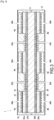
- the tooling 1 for manufacturing a part made of ceramic matrix composite material comprises an injection chamber 2 in which a fibrous preform 3 is installed.
- FIG 1a illustrates the tooling 1 without the fibrous preform 3, thus making the injection chamber 2 visible
- figure 1b illustrates tooling 1 when the fibrous preform 3 is installed in the injection chamber 2.
- the fibrous preform 3 is densified by injection of a slip.
- the slip is formed by a liquid phase loaded with ceramic particles, the ceramic particles being intended to be deposited in the fibrous preform 3 in order to densify it and form the ceramic matrix.
- the liquid phase of the slip can in particular be formed by water (acidic or basic pH), ethanol, or any other liquid in which it is possible to suspend the desired powder.
- An organic binder can also be added (PVA, PEG, PVP, soluble in water). This binder ensures that the raw material holds together after drying and before sintering.
- the ceramic particles in the slip may be alumina, mullite, silica, zirconia, aluminosilicate or aluminophosphate, or a mixture of these components.
- the ceramic particles can also be made of carbide, for example silicon carbide.
- the average size, or average particle size, of the particles is between 0.1 ⁇ m and 10 ⁇ m. By “average size” we designate the dimension given by the statistical particle size distribution at half of the population, called D50.
- the injection chamber 2 is formed by the cooperation between a rigid mold 11 and an equally rigid counter-mold 12.
- the counter-mold 12 defines a first face 21 of the injection chamber 2, and the mold 11 defines a second face 22 of said injection chamber 2, the second face 22 being opposite the first face 21.
- the fibrous preform 3 to be densified is placed in an impression formed on the mold 11, then the counter-mold 12 is placed in front of the mold 11 and compresses the fibrous preform 3 in order on the one hand to give it the desired shape, and on the other hand to ensure that the part to be manufactured has a desired fiber volume ratio.
- the fibrous preform 3 comprises a first face 30a directed towards the counter-mold 12, and a second face 30b opposite the first face 30a and which is directed towards the mold 11.
- said injection chamber 2 comprises a plurality of first injection orifices 23a which are formed in the first face 21 of said injection chamber 2.
- the first injection orifices 23a are distributed along the first face 21.
- said injection chamber 2 comprises a plurality of first drainage orifices 24a which are formed in the first face 21.
- the first drainage orifices 24a are distributed along the first face 21.
- the tooling 1 comprises a first filtration element 4a which is located opposite the orifices of drainage 24, said first filtration element 4a being located on the first face 21 of the injection chamber 2.
- the first filtration element 4a is configured to allow the liquid phase of the slip to pass but retain the ceramic particles.
- the first filtration element 4a can be a porous element whose size of porosities is adapted to the size of the ceramic particles of the slip so that said ceramic particles of the slip do not pass through said first filtration element 4a and thus are retained in the injection chamber.
- the first injection orifices 23a and the first drainage orifices 24a are formed in the counter-mold 12, but according to another possible variant the first injection orifices 23a and the first drainage orifices 24a are formed in the mold 11 (and are thus formed in the second face 22), and the first filtration element 4a is located opposite the first drainage orifices 24 on the mold 11.
- first injection orifices 23a and the first drainage orifices 24a are formed and distributed along the same face of the injection chamber 2 makes it possible to inject and drain the fibrous preform through the same face. 3, thus making it possible to densify the fibrous preform 3 even when one face of said fibrous preform 3 is not accessible.
- the tooling 1 comprises a plurality of first injection orifices 23a and a plurality of first drainage orifices 24a allows more homogeneous densification of the fibrous preform 3.
- first injection orifices 23a The multiplicity of first injection orifices 23a and first drainage orifices 24a makes it possible to limit the concentration of particles at the level of the first injection orifices 23a.
- the fibrous preform 3 can comprise a surface area of between 200 ⁇ 200mm and a few m 2 .
- At least one first injection orifice 23a is located between two first drainage orifices 24a.
- each first injection orifice 23a is located between two first drainage orifices 24a.
- the diameter of the first injection orifices 23a and the first drainage orifices 24a is adapted so that said first injection orifices 23a and said first drainage orifices 24a represent between 2% and 30% of the surface of the first face 21 of the injection chamber 2.
- the drilling surface of the first injection orifices 23a, plus the drilling surface of the drainage orifices 24a corresponds to between 2% and 30% of the surface of the first face 21 of the injection chamber 2.
- between 10% and 20% of the surface of the first face 21 can be pierced by the first injection orifices 23a and the first drainage orifices 24a . This characteristic makes it possible to improve the homogeneity of the deposition of the ceramic particles inside the fibrous preform 3.
- the surface of the first face 21 of the injection chamber is very close to the surface of the fibrous preform 3.
- the injection chamber 2 comprises a first end 2a and a second end 2b which is opposite the first end 2a, a first drainage orifice 24a being located at the first end 2a and another first drainage orifice 24a being located at the second end 2b.
- the first drainage orifice 24a located at the first end 2a of the injection chamber 2 is located opposite a first end 3a of said fibrous preform 3, while the first drainage orifice 24a located at the second end 2b of the injection chamber 2 is located opposite a second end 3b of said fibrous preform 3 which is opposite the first end 3a.
- first drainage orifices 24a are located at the ends of the injection chamber 2 makes it possible to position first drainage orifices 24 at the ends of the fibrous preform 3, and thus ensures better circulation of the slip to the ends of the fibrous preform 3, thus improving the homogeneity of the densification of said fibrous preform 3.
- a mesh 25 can be placed in the first injection orifices 23a in order on the one hand to prevent the threads of the fibrous preform 3 from forming a bulge at the level of the first injection orifices 23, and on the other hand improve the distribution of the slip.
- a mesh 26 can also be placed in the first drainage orifices 24a, over the first filtration element 4a.
- the first filtration element 4a is located between the fibrous preform 3 and the mesh 26.
- the mesh 26 located in the first drainage orifices 24a ensures that the filtration element 4 is maintained in the first drainage orifices 24a.
- the fibrous preform 3 comprises a thickness which is less than or equal to 10mm. Such a thickness of the fibrous preform 3 is suitable for injection and drainage of the slip through the same face, making it possible to improve the deposition of ceramic particles within said fibrous preform 3, and in particular at the level of the face of the fibrous preform 3 which is opposite the first face 21 of the injection chamber 2.
- the compaction of the fibrous preform 3 can be carried out by cooperation of the mold 11 with a flexible membrane 13, instead of the cooperation of the mold 11 with a counter-mold 12 as is achieved in the first variant of the figures 1a And 1b .
- the fibrous preform 3 is installed in the injection chamber 2 which is formed by the flexible membrane 13 and the mold 11, the flexible membrane 13 forming the first face 21 of the injection chamber 2 and the mold 11 forming the second face 22 of said injection chamber 2.
- the first face 30a of the fibrous preform is directed towards the flexible membrane 13, and the second face 30b is directed towards the mold 11.
- the fibrous preform 3 is placed in the injection chamber 2, the fibrous preform 3 is compacted by the flexible membrane 13 so that the part to be manufactured has the desired fiber volume ratio, and said fibrous preform 3 is densified by injection of the slip into the injection chamber 2 via the plurality of first injection orifices 23a formed in the first face 21 of the injection chamber 2. The slip is drained through the first drainage orifices 24a.
- the arrangement of the first injection orifices 23a and the first drainage orifices 24a of the tool 1 according to the second variant illustrated on the figure 2 may be similar to that of the first variant illustrated on the figures 1a And 1b .
- the first injection orifices 23a are not arranged between two first drainage orifices 24a, however the first injection orifices 23a can be arranged between two first drainage orifices 24a.
- the tooling 1 according to the second variant illustrated on the figure 2 comprises a first filtration element 4a which is located opposite the first drainage orifices 24a in order to retain the ceramic particles inside the fibrous preform 3.
- the first filtration element 4a is located between the fibrous preform 3 and the first face 21 of the injection chamber 2.
- the tool 1 may include a draining felt 5 which is placed between the flexible membrane 13 and the first filtration element 4a.
- the draining felt facilitates the circulation of the fluid towards the drainage orifices 24a.
- the tooling 1 according to the second variant may comprise a mesh 25 arranged in the first injection orifices 23a in order, on the one hand, to prevent the threads of the fibrous preform 3 from forming a bulge at the level of the first injection orifices 23a, and on the other hand to improve the distribution of the slip.
- the fibrous preform 3 alone is installed in the injection chamber 2.
- the fibrous preform 3 can be installed in the injection chamber 2 by being fixed on a support, said support being able for example to be an insulation layer acoustic, or a structural layer.
- the support is a central core and the part to be manufactured comprises two fibrous preforms arranged on either side of the central core, the variants illustrated on the figures 1a , 1b And 2 are not suitable for simultaneously densifying the two fibrous preforms.
- FIG. 3 and the figure 4 respectively illustrate a third variant and a fourth variant of tooling 1 making it possible to densify in one go a part which comprises a first fibrous preform 31 and a second fibrous preform 32 which are located on either side of a central core 6.
- at least one of the fibrous preform 31 and the second fibrous preform 32 comprises a thickness less than or equal to 10mm, advantageously the fibrous preform 31 and the second fibrous preform 32 both comprise a thickness less than or equal to 10mm.
- the first fibrous preform 31 comprises a first face 31a which is directed opposite the first face 21 of injection chamber 2, and a second face 31b opposite the first face 31a and which is fixed to the central core 6.
- second fibrous preform 32 comprises a first face 32a which is directed opposite the second face 22 of injection chamber 2, and a second face 32b opposite the first face 32a and which is fixed to the central core 6.
- the central core 6 can for example be an acoustic insulation layer, or a structural layer which has the function of improving the mechanical strength of the part to be manufactured.
- the central core 6 may in particular be a honeycomb structure.
- the tool 1 in addition to having a plurality of first injection orifices 23a and a plurality of first drainage orifices 24a on the first face 21 of the injection chamber 2, the tool 1 comprises a plurality of second orifices injection 23b and a plurality of second drainage orifices 24b on the second face 22 of the injection chamber 2.
- the injection chamber 2 is formed by the cooperation of the mold 11 and the counter-mold 12.
- the counter-mold 12 forms the first face 21 of the injection chamber 2 while the mold 11 forms the second face 22 of said injection chamber 2.
- the distribution of the first injection orifices 23a and the first drainage orifices 24a on the counter-mold 12 in the third variant is similar to the distribution of the first injection orifices 23a and the first drainage orifices 24a on the counter-mold 12 in the first variant.
- the distribution of the second injection orifices 23b and the second drainage orifices 24b on the mold 11 can be similar to the distribution of the first injection orifices 23a and the first drainage orifices 24a on the counter-mold 12.
- the injection chamber 2 is formed by the cooperation of the mold 11 and the flexible membrane 13.
- the flexible membrane 13 forms the first face 21 of the injection chamber 2 while the mold 11 forms the second face 22 of said injection chamber 2.
- the distribution of the first injection orifices 23a and the first drainage orifices 24a on the flexible membrane 13 in the fourth variant is similar to the distribution of the first injection orifices 23a and the first drainage orifices 24a on the flexible membrane 13 in the second variant. Furthermore, in the fourth variant illustrated on the Figure 3 , the distribution of the second injection orifices 23b and the second drainage orifices 24b on the mold 11 is similar to the distribution of the first injection orifices 23a and the first drainage orifices 24a on the mold 11 of the third variant.
- the tooling 1 of the third variant and the fourth variant comprises a second filtration element 4b which is located opposite the second drainage orifices 24b formed in the second face 22 of the injection chamber 2.
- the tooling 1 comprises the first filtration element 4a which is located opposite the first drainage orifices 24a formed in the first face 21 of the injection chamber 2.
- tooling 1 of the third variant and the fourth variant of the figures 3 And 4 makes it possible to simultaneously densify the first fibrous preform 31 and the second fibrous preform 32 by injecting and draining the slip through the same face of said first fibrous preform 31 and second fibrous preform 32.
- the fibrous preform is densified, said fibrous preform is dried, then demolded and the ceramic particles can be sintered. Furthermore, in the case of a carbide/carbide composite part, molten metal such as silicon can be injected into the porosities of the ceramic matrix composite material.
- injection steps E2 and E2' can advantageously be carried out simultaneously, and the drainage steps E3 and E3' can also be advantageously carried out simultaneously.
- the first and second fibrous preforms 31 and 32 are dried, then demolded and the ceramic particles can be sintered.
- molten metal such as silicon can be injected into the porosities of the ceramic matrix composite material.
- the method may comprise a step of sealing E0 of the support with the slip before the step of injecting E2 and/or E2' of the slip into the fibrous texture(s).
- the sealing step E0 of the support is carried out by injection of a fugitive material, for example polymethyl methacrylate (PMMA) into the porosities of said support.
- PMMA polymethyl methacrylate
- the method also includes a step E4 of eliminating the fugitive material after the step of draining E3 and/or E3' of the liquid phase.
- the fugitive material can, for example, be eliminated by melting then casting, or by thermal decomposition (pyrolysis).
Landscapes
- Engineering & Computer Science (AREA)
- Chemical & Material Sciences (AREA)
- Ceramic Engineering (AREA)
- Manufacturing & Machinery (AREA)
- Mechanical Engineering (AREA)
- Materials Engineering (AREA)
- Structural Engineering (AREA)
- Organic Chemistry (AREA)
- Dispersion Chemistry (AREA)
- Chemical Kinetics & Catalysis (AREA)
- Composite Materials (AREA)
- Filtering Materials (AREA)
- Manufacture Of Alloys Or Alloy Compounds (AREA)
- Producing Shaped Articles From Materials (AREA)
Claims (13)
- Werkzeug (1) zur Herstellung eines Teils aus Verbundmaterial mit keramischer Matrix durch Einspritzen eines Tonschlamms, wobei das Werkzeug (1) eine Einspritzkammer (2) umfasst, die dazu bestimmt ist, zumindest eine zu verdichtende Faser-Vorform (3) aufzunehmen, und- die Einspritzkammer (2) mehrere erste Einspritzöffnungen (23a) umfasst, die in einer ersten Seitenfläche (21) der Einspritzkammer (2) für die Einspritzung des Tonschlamms in das Innere der Einspritzkammer (2) gebildet sind, wobei die ersten Einspritzöffnungen (23a) entlang der ersten Seitenfläche (21) der Einspritzkammer (2) verteilt sind,- die Einspritzkammer (2) mehrere erste Abzugsöffnungen (24a) umfasst, die auf der ersten Seitenfläche (21) der Einspritzkammer (2) für das Abziehen einer flüssigen Phase des Tonschlamms aus der Einspritzkammer (2) gebildet sind, wobei die ersten Abzugsöffnungen (24a) entlang der ersten Seitenfläche (21) der Einspritzkammer (2) verteilt sind, und- das Werkzeug (1) ein erstes Filtrationselement (4) umfasst, das sich auf der ersten Seitenfläche (21) der Einspritzkammer (2) befindet und das sich gegenüber den ersten Abzugsöffnungen (24a) befindet.
- Werkzeug (1) nach Anspruch 1, wobei zwischen 2 % und 30 % der Oberfläche der ersten Seitenfläche (21) der Einspritzkammer (2) von den ersten Einspritzöffnungen (23a) und den ersten Abzugsöffnungen (24a) durchdrungen werden.
- Werkzeug (1) nach einem der Ansprüche 1 bis 2, wobei zumindest eine erste Einspritzöffnung (23a) sich zwischen zwei ersten Abzugsöffnungen (24a) befindet.
- Werkzeug (1) nach einem der Ansprüche 1 bis 3, wobei die Einspritzkammer (2) ein erstes Ende (2a) und ein zweites Ende (2b) gegenüber dem ersten Ende (2a) umfasst, wobei eine erste Abzugsöffnung (24a) sich an dem ersten Ende (2a) der Einspritzkammer (2) befindet und eine erste Abzugsöffnung (24a) sich an dem zweiten Ende (2b) der Einspritzkammer (2) befindet.
- Werkzeug (1) nach einem der Ansprüche 1 bis 4, wobei mehrere zweite Einspritzöffnungen (23b) sich auf einer zweiten Seitenfläche (22) der Einspritzkammer (2) befinden, die der ersten Seitenfläche (21) der Einspritzkammer (2) gegenüberliegt, wobei mehrere zweite Abzugsöffnungen (24b) sich auf der zweiten Seitenfläche (22) der Einspritzkammer (2) befinden, und wobei ein zweites Filtrationselement (4b) sich auf der zweiten Seitenfläche (22) der Einspritzkammer (2) gegenüber den zweiten Abzugsöffnungen (24b) befindet.
- Werkzeug (1) nach einem der Ansprüche 1 bis 5, wobei das Werkzeug (1) eine steife und fixierte Form (11) umfasst, die eine zweite Seitenfläche (22) der Einspritzkammer (2) gegenüber der ersten Seitenfläche (21) der Einspritzkammer (2) bildet, und wobei das Werkzeug (1) eine steife und bewegliche Gegenform (12) umfasst, welche die erste Seitenfläche (21) der Einspritzkammer (2) bildet.
- Werkzeug (1) nach einem der Ansprüche 1 bis 5, wobei das Werkzeug (1) eine steife und fixierte Form (11) umfasst, die eine zweite Seitenfläche (22) der Einspritzkammer (2) gegenüber der ersten Seitenfläche (21) der Einspritzkammer (2) bildet, und wobei das Werkzeug (1) eine flexible Membran (13) umfasst, welche die erste Seitenfläche (21) der Einspritzkammer (2) bildet.
- Werkzeug (1) nach Anspruch 7, wobei ein Entwässerungsfilz (5) zwischen dem ersten Filtrationselement (4a) und den ersten Abzugsöffnungen (24a) vorgesehen ist.
- Verfahren zur Herstellung eines Teils aus Verbundmaterial mit keramischer Matrix, umfassend die folgenden Schritte:- (E1): Platzieren einer ersten Faser-Vorform (3, 31) in einer Einspritzkammer (2), die in einem Werkzeug (1) nach einem der Ansprüche 1 bis 8 gebildet ist,- (E2): Einspritzen eines Tonschlamms, der keramische Partikel in Suspension in einer flüssigen Phase umfasst, in die erste Faser-Vorform (3, 31) durch eine erste Seitenfläche (30a, 31a) der ersten Faser-Vorform (3, 31) durch mehrere erste Einspritzöffnungen (23a),- (E3): Abziehen, durch mehrere erste Abzugsöffnungen (24a), der flüssigen Phase des Tonschlamms durch die erste Seitenfläche (30a, 31a) der ersten Faser-Vorform (3, 31) über ein erstes Filtrationselement (4a), das dazu ausgestaltet ist, die keramischen Partikel in der ersten Faser-Vorform (3, 31) zurückzuhalten.
- Verfahren nach Anspruch 9, umfassend ferner die folgenden Schritte:- (E10): Platzieren der ersten Faser-Vorform (31) und einer zweiten Faser-Vorform (32) in der Einspritzkammer (2), wobei die erste Faser-Vorform (31) und die zweite Faser-Vorform (32) sich auf beiden Seiten eines zentralen Kerns (6) befinden,- (E2'): Einspritzen, durch mehrere zweite Einspritzöffnungen (23b), des Tonschlamms in die zweite Faser-Vorform (32) durch eine erste Seitenfläche (32a) der zweiten Faser-Vorform (32),- (E3'): Abziehen, durch mehrere zweite Abzugsöffnungen (24b), der flüssigen Phase des Tonschlamms durch die erste Seitenfläche (32a) der zweiten Faser-Vorform (32) über ein zweites Filtrationselement (4b), das dazu ausgestaltet ist, die keramischen Partikel in der zweiten Faser-Vorform (32) zurückzuhalten.
- Verfahren nach einem der Ansprüche 9 oder 10, wobei die erste Faser-Vorform (3, 31) auf einem porösen Träger fixiert ist, wobei das Verfahren einen Schritt der Abdichtung (E0) des Trägers gegenüber dem Tonschlamm vor dem Schritt der Einspritzung (E2, E2') des Tonschlamms in die erste Faser-Vorform (3, 31) umfasst, durch Einspritzung eines flüchtigen Materials in die Poren des Trägers, wobei das Verfahren ferner einen Schritt der Entfernung des flüchtigen Materials (E4) nach dem Abziehen der flüssigen Phase des Tonschlamms umfasst.
- Verfahren nach einem der Ansprüche 9 bis 11, wobei die erste Faser-Vorform (3, 31) eine Dicke kleiner oder gleich 10 mm aufweist.
- Verfahren nach einem der Ansprüche 10 oder 11, wobei zumindest eine aus der ersten Faser-Vorform (31) und der zweiten Faser-Vorform (32) eine Dicke kleiner oder gleich 10 mm aufweist.
Applications Claiming Priority (2)
| Application Number | Priority Date | Filing Date | Title |
|---|---|---|---|
| FR1874009A FR3090627B1 (fr) | 2018-12-21 | 2018-12-21 | Outillage et procédé de fabrication d’une pièce en matériau composite par voie liquide |
| PCT/FR2019/053205 WO2020128364A1 (fr) | 2018-12-21 | 2019-12-19 | Outillage et procede de fabrication d'une piece en materiau composite par voie liquide |
Publications (2)
| Publication Number | Publication Date |
|---|---|
| EP3898147A1 EP3898147A1 (de) | 2021-10-27 |
| EP3898147B1 true EP3898147B1 (de) | 2023-10-04 |
Family
ID=67383837
Family Applications (1)
| Application Number | Title | Priority Date | Filing Date |
|---|---|---|---|
| EP19848791.0A Active EP3898147B1 (de) | 2018-12-21 | 2019-12-19 | Werkzeug und verfahren zur herstellung eines verbundwerkstoffteils mittels eines flüssigen verfahrens |
Country Status (4)
| Country | Link |
|---|---|
| US (1) | US12172339B2 (de) |
| EP (1) | EP3898147B1 (de) |
| FR (1) | FR3090627B1 (de) |
| WO (1) | WO2020128364A1 (de) |
Family Cites Families (5)
| Publication number | Priority date | Publication date | Assignee | Title |
|---|---|---|---|---|
| FR2097382A5 (de) * | 1970-07-03 | 1972-03-03 | Eternit Ste Francaise | |
| DE19841047C1 (de) * | 1998-09-09 | 2000-01-13 | Hochtief Ag Hoch Tiefbauten | Verfahren und Vorrichtung zum Herstellen von Tübbingen für eine Tunnelauskleidung |
| ES2628600T3 (es) * | 2002-10-09 | 2017-08-03 | Toray Industries, Inc. | Método de moldeo de RTM |
| FR3030505B1 (fr) | 2014-12-23 | 2019-07-12 | Safran | Procede de fabrication d'une preforme fibreuse chargee de particules ceramiques refractaires |
| FR3050454B1 (fr) | 2016-04-25 | 2019-07-12 | Safran | Procede de fabrication d'une piece en materiau composite par injection d'une barbotine chargee dans une texture fibreuse |
-
2018
- 2018-12-21 FR FR1874009A patent/FR3090627B1/fr active Active
-
2019
- 2019-12-19 WO PCT/FR2019/053205 patent/WO2020128364A1/fr not_active Ceased
- 2019-12-19 EP EP19848791.0A patent/EP3898147B1/de active Active
- 2019-12-19 US US17/414,765 patent/US12172339B2/en active Active
Also Published As
| Publication number | Publication date |
|---|---|
| EP3898147A1 (de) | 2021-10-27 |
| WO2020128364A1 (fr) | 2020-06-25 |
| US20220016801A1 (en) | 2022-01-20 |
| US12172339B2 (en) | 2024-12-24 |
| FR3090627B1 (fr) | 2021-01-15 |
| FR3090627A1 (fr) | 2020-06-26 |
Similar Documents
| Publication | Publication Date | Title |
|---|---|---|
| EP3448829B1 (de) | Verfahren zur herstellung eines teils aus einem verbundmaterial durch injektion einer beladenen schlämme in eine faserige textur | |
| EP3237660B1 (de) | Verfahren zur herstellung eines mit keramischen, feuerfesten partikeln gefüllten faservorformlings | |
| EP3774690B1 (de) | Verfahren zur herstellung eines teils aus einem verbundwerkstoff mittels injektion einer beladenen keramikaufschlämmung in eine fasrige struktur | |
| EP3359506B1 (de) | Verfahren zur herstellung eines keramik-verbundwerkstoffs durch einspritzen eines gefüllten schlickers in einer porösen form | |
| EP3768405B1 (de) | Verfahren zur herstellung eines teils aus einem keramikverbundwerkstoff durch einspritzen von pulver in eine faserverstärkung mit entwässerung durch eine verbundfilterschicht | |
| EP3237358B1 (de) | Verfahren zur herstellung eines feuerfesten verbundkörpers | |
| EP2815118A1 (de) | Auslasskonus mit schalldämpfungsanordnung | |
| EP3996889B1 (de) | Verfahren zur herstellung eines teils aus einem verbundmaterial durch injektion einer gefüllten schlämme in eine faserige textur | |
| CA3076441A1 (fr) | Procede de fabrication d'une piece en cmc | |
| EP3898147B1 (de) | Werkzeug und verfahren zur herstellung eines verbundwerkstoffteils mittels eines flüssigen verfahrens | |
| EP3863992B1 (de) | Verfahren zur herstellung eines teils aus verbundstoff mit nachgiebigkeitskontrolle | |
| WO2019058069A1 (fr) | Procede de fabrication d'une piece en cmc | |
| EP4355542B1 (de) | Verfahren zum einspritzen von keramikpulvern mit in-situ erzeugtem filter in die faservorform | |
| FR3032967A1 (fr) | Panneau d’attenuation acoustique en materiau composite, comportant des reseaux de cavites formes par des granulats | |
| EP4017721A1 (de) | Schalldämmstruktur aus verbundwerkstoff und ihr herstellungsverfahren | |
| FR3124965A1 (fr) | Procédé de fabrication d’une pièce en matériau composite par injection d’une barbotine chargée dans une texture fibreuse |
Legal Events
| Date | Code | Title | Description |
|---|---|---|---|
| STAA | Information on the status of an ep patent application or granted ep patent |
Free format text: STATUS: UNKNOWN |
|
| STAA | Information on the status of an ep patent application or granted ep patent |
Free format text: STATUS: THE INTERNATIONAL PUBLICATION HAS BEEN MADE |
|
| PUAI | Public reference made under article 153(3) epc to a published international application that has entered the european phase |
Free format text: ORIGINAL CODE: 0009012 |
|
| STAA | Information on the status of an ep patent application or granted ep patent |
Free format text: STATUS: REQUEST FOR EXAMINATION WAS MADE |
|
| 17P | Request for examination filed |
Effective date: 20210614 |
|
| AK | Designated contracting states |
Kind code of ref document: A1 Designated state(s): AL AT BE BG CH CY CZ DE DK EE ES FI FR GB GR HR HU IE IS IT LI LT LU LV MC MK MT NL NO PL PT RO RS SE SI SK SM TR |
|
| DAV | Request for validation of the european patent (deleted) | ||
| DAX | Request for extension of the european patent (deleted) | ||
| GRAP | Despatch of communication of intention to grant a patent |
Free format text: ORIGINAL CODE: EPIDOSNIGR1 |
|
| STAA | Information on the status of an ep patent application or granted ep patent |
Free format text: STATUS: GRANT OF PATENT IS INTENDED |
|
| RIC1 | Information provided on ipc code assigned before grant |
Ipc: B28B 7/36 20060101ALI20230315BHEP Ipc: C04B 35/80 20060101ALI20230315BHEP Ipc: C04B 35/486 20060101ALI20230315BHEP Ipc: C04B 35/14 20060101ALI20230315BHEP Ipc: C04B 35/111 20060101ALI20230315BHEP Ipc: B28B 23/00 20060101ALI20230315BHEP Ipc: C04B 35/447 20060101ALI20230315BHEP Ipc: C04B 35/185 20060101ALI20230315BHEP Ipc: C04B 35/18 20060101ALI20230315BHEP Ipc: B28B 19/00 20060101ALI20230315BHEP Ipc: B28B 7/34 20060101ALI20230315BHEP Ipc: B28B 1/26 20060101ALI20230315BHEP Ipc: B28B 1/24 20060101AFI20230315BHEP |
|
| INTG | Intention to grant announced |
Effective date: 20230417 |
|
| RIN1 | Information on inventor provided before grant (corrected) |
Inventor name: CLERAMBOURG, AURELIA Inventor name: BOUNIA, MEDHY DAMIEN Inventor name: PHILIPPE, ERIC |
|
| GRAS | Grant fee paid |
Free format text: ORIGINAL CODE: EPIDOSNIGR3 |
|
| GRAA | (expected) grant |
Free format text: ORIGINAL CODE: 0009210 |
|
| STAA | Information on the status of an ep patent application or granted ep patent |
Free format text: STATUS: THE PATENT HAS BEEN GRANTED |
|
| AK | Designated contracting states |
Kind code of ref document: B1 Designated state(s): AL AT BE BG CH CY CZ DE DK EE ES FI FR GB GR HR HU IE IS IT LI LT LU LV MC MK MT NL NO PL PT RO RS SE SI SK SM TR |
|
| REG | Reference to a national code |
Ref country code: GB Ref legal event code: FG4D Free format text: NOT ENGLISH |
|
| REG | Reference to a national code |
Ref country code: CH Ref legal event code: EP |
|
| REG | Reference to a national code |
Ref country code: DE Ref legal event code: R096 Ref document number: 602019038833 Country of ref document: DE |
|
| REG | Reference to a national code |
Ref country code: IE Ref legal event code: FG4D Free format text: LANGUAGE OF EP DOCUMENT: FRENCH |
|
| REG | Reference to a national code |
Ref country code: LT Ref legal event code: MG9D |
|
| REG | Reference to a national code |
Ref country code: NL Ref legal event code: MP Effective date: 20231004 |
|
| REG | Reference to a national code |
Ref country code: AT Ref legal event code: MK05 Ref document number: 1617284 Country of ref document: AT Kind code of ref document: T Effective date: 20231004 |
|
| PG25 | Lapsed in a contracting state [announced via postgrant information from national office to epo] |
Ref country code: NL Free format text: LAPSE BECAUSE OF FAILURE TO SUBMIT A TRANSLATION OF THE DESCRIPTION OR TO PAY THE FEE WITHIN THE PRESCRIBED TIME-LIMIT Effective date: 20231004 |
|
| PG25 | Lapsed in a contracting state [announced via postgrant information from national office to epo] |
Ref country code: GR Free format text: LAPSE BECAUSE OF FAILURE TO SUBMIT A TRANSLATION OF THE DESCRIPTION OR TO PAY THE FEE WITHIN THE PRESCRIBED TIME-LIMIT Effective date: 20240105 |
|
| PG25 | Lapsed in a contracting state [announced via postgrant information from national office to epo] |
Ref country code: IS Free format text: LAPSE BECAUSE OF FAILURE TO SUBMIT A TRANSLATION OF THE DESCRIPTION OR TO PAY THE FEE WITHIN THE PRESCRIBED TIME-LIMIT Effective date: 20240204 |
|
| PG25 | Lapsed in a contracting state [announced via postgrant information from national office to epo] |
Ref country code: LT Free format text: LAPSE BECAUSE OF FAILURE TO SUBMIT A TRANSLATION OF THE DESCRIPTION OR TO PAY THE FEE WITHIN THE PRESCRIBED TIME-LIMIT Effective date: 20231004 |
|
| PG25 | Lapsed in a contracting state [announced via postgrant information from national office to epo] |
Ref country code: AT Free format text: LAPSE BECAUSE OF FAILURE TO SUBMIT A TRANSLATION OF THE DESCRIPTION OR TO PAY THE FEE WITHIN THE PRESCRIBED TIME-LIMIT Effective date: 20231004 |
|
| PG25 | Lapsed in a contracting state [announced via postgrant information from national office to epo] |
Ref country code: ES Free format text: LAPSE BECAUSE OF FAILURE TO SUBMIT A TRANSLATION OF THE DESCRIPTION OR TO PAY THE FEE WITHIN THE PRESCRIBED TIME-LIMIT Effective date: 20231004 |
|
| PG25 | Lapsed in a contracting state [announced via postgrant information from national office to epo] |
Ref country code: LT Free format text: LAPSE BECAUSE OF FAILURE TO SUBMIT A TRANSLATION OF THE DESCRIPTION OR TO PAY THE FEE WITHIN THE PRESCRIBED TIME-LIMIT Effective date: 20231004 Ref country code: IS Free format text: LAPSE BECAUSE OF FAILURE TO SUBMIT A TRANSLATION OF THE DESCRIPTION OR TO PAY THE FEE WITHIN THE PRESCRIBED TIME-LIMIT Effective date: 20240204 Ref country code: GR Free format text: LAPSE BECAUSE OF FAILURE TO SUBMIT A TRANSLATION OF THE DESCRIPTION OR TO PAY THE FEE WITHIN THE PRESCRIBED TIME-LIMIT Effective date: 20240105 Ref country code: ES Free format text: LAPSE BECAUSE OF FAILURE TO SUBMIT A TRANSLATION OF THE DESCRIPTION OR TO PAY THE FEE WITHIN THE PRESCRIBED TIME-LIMIT Effective date: 20231004 Ref country code: BG Free format text: LAPSE BECAUSE OF FAILURE TO SUBMIT A TRANSLATION OF THE DESCRIPTION OR TO PAY THE FEE WITHIN THE PRESCRIBED TIME-LIMIT Effective date: 20240104 Ref country code: AT Free format text: LAPSE BECAUSE OF FAILURE TO SUBMIT A TRANSLATION OF THE DESCRIPTION OR TO PAY THE FEE WITHIN THE PRESCRIBED TIME-LIMIT Effective date: 20231004 Ref country code: PT Free format text: LAPSE BECAUSE OF FAILURE TO SUBMIT A TRANSLATION OF THE DESCRIPTION OR TO PAY THE FEE WITHIN THE PRESCRIBED TIME-LIMIT Effective date: 20240205 |
|
| PG25 | Lapsed in a contracting state [announced via postgrant information from national office to epo] |
Ref country code: SE Free format text: LAPSE BECAUSE OF FAILURE TO SUBMIT A TRANSLATION OF THE DESCRIPTION OR TO PAY THE FEE WITHIN THE PRESCRIBED TIME-LIMIT Effective date: 20231004 Ref country code: RS Free format text: LAPSE BECAUSE OF FAILURE TO SUBMIT A TRANSLATION OF THE DESCRIPTION OR TO PAY THE FEE WITHIN THE PRESCRIBED TIME-LIMIT Effective date: 20231004 Ref country code: PL Free format text: LAPSE BECAUSE OF FAILURE TO SUBMIT A TRANSLATION OF THE DESCRIPTION OR TO PAY THE FEE WITHIN THE PRESCRIBED TIME-LIMIT Effective date: 20231004 Ref country code: NO Free format text: LAPSE BECAUSE OF FAILURE TO SUBMIT A TRANSLATION OF THE DESCRIPTION OR TO PAY THE FEE WITHIN THE PRESCRIBED TIME-LIMIT Effective date: 20240104 Ref country code: LV Free format text: LAPSE BECAUSE OF FAILURE TO SUBMIT A TRANSLATION OF THE DESCRIPTION OR TO PAY THE FEE WITHIN THE PRESCRIBED TIME-LIMIT Effective date: 20231004 Ref country code: HR Free format text: LAPSE BECAUSE OF FAILURE TO SUBMIT A TRANSLATION OF THE DESCRIPTION OR TO PAY THE FEE WITHIN THE PRESCRIBED TIME-LIMIT Effective date: 20231004 |
|
| REG | Reference to a national code |
Ref country code: DE Ref legal event code: R097 Ref document number: 602019038833 Country of ref document: DE |
|
| PG25 | Lapsed in a contracting state [announced via postgrant information from national office to epo] |
Ref country code: DK Free format text: LAPSE BECAUSE OF FAILURE TO SUBMIT A TRANSLATION OF THE DESCRIPTION OR TO PAY THE FEE WITHIN THE PRESCRIBED TIME-LIMIT Effective date: 20231004 |
|
| PG25 | Lapsed in a contracting state [announced via postgrant information from national office to epo] |
Ref country code: CZ Free format text: LAPSE BECAUSE OF FAILURE TO SUBMIT A TRANSLATION OF THE DESCRIPTION OR TO PAY THE FEE WITHIN THE PRESCRIBED TIME-LIMIT Effective date: 20231004 |
|
| PG25 | Lapsed in a contracting state [announced via postgrant information from national office to epo] |
Ref country code: SK Free format text: LAPSE BECAUSE OF FAILURE TO SUBMIT A TRANSLATION OF THE DESCRIPTION OR TO PAY THE FEE WITHIN THE PRESCRIBED TIME-LIMIT Effective date: 20231004 |
|
| PG25 | Lapsed in a contracting state [announced via postgrant information from national office to epo] |
Ref country code: SM Free format text: LAPSE BECAUSE OF FAILURE TO SUBMIT A TRANSLATION OF THE DESCRIPTION OR TO PAY THE FEE WITHIN THE PRESCRIBED TIME-LIMIT Effective date: 20231004 Ref country code: SK Free format text: LAPSE BECAUSE OF FAILURE TO SUBMIT A TRANSLATION OF THE DESCRIPTION OR TO PAY THE FEE WITHIN THE PRESCRIBED TIME-LIMIT Effective date: 20231004 Ref country code: RO Free format text: LAPSE BECAUSE OF FAILURE TO SUBMIT A TRANSLATION OF THE DESCRIPTION OR TO PAY THE FEE WITHIN THE PRESCRIBED TIME-LIMIT Effective date: 20231004 Ref country code: IT Free format text: LAPSE BECAUSE OF FAILURE TO SUBMIT A TRANSLATION OF THE DESCRIPTION OR TO PAY THE FEE WITHIN THE PRESCRIBED TIME-LIMIT Effective date: 20231004 Ref country code: EE Free format text: LAPSE BECAUSE OF FAILURE TO SUBMIT A TRANSLATION OF THE DESCRIPTION OR TO PAY THE FEE WITHIN THE PRESCRIBED TIME-LIMIT Effective date: 20231004 Ref country code: DK Free format text: LAPSE BECAUSE OF FAILURE TO SUBMIT A TRANSLATION OF THE DESCRIPTION OR TO PAY THE FEE WITHIN THE PRESCRIBED TIME-LIMIT Effective date: 20231004 Ref country code: CZ Free format text: LAPSE BECAUSE OF FAILURE TO SUBMIT A TRANSLATION OF THE DESCRIPTION OR TO PAY THE FEE WITHIN THE PRESCRIBED TIME-LIMIT Effective date: 20231004 |
|
| REG | Reference to a national code |
Ref country code: CH Ref legal event code: PL |
|
| PLBE | No opposition filed within time limit |
Free format text: ORIGINAL CODE: 0009261 |
|
| STAA | Information on the status of an ep patent application or granted ep patent |
Free format text: STATUS: NO OPPOSITION FILED WITHIN TIME LIMIT |
|
| PG25 | Lapsed in a contracting state [announced via postgrant information from national office to epo] |
Ref country code: LU Free format text: LAPSE BECAUSE OF NON-PAYMENT OF DUE FEES Effective date: 20231219 |
|
| PG25 | Lapsed in a contracting state [announced via postgrant information from national office to epo] |
Ref country code: MC Free format text: LAPSE BECAUSE OF FAILURE TO SUBMIT A TRANSLATION OF THE DESCRIPTION OR TO PAY THE FEE WITHIN THE PRESCRIBED TIME-LIMIT Effective date: 20231004 |
|
| REG | Reference to a national code |
Ref country code: BE Ref legal event code: MM Effective date: 20231231 |
|
| PG25 | Lapsed in a contracting state [announced via postgrant information from national office to epo] |
Ref country code: MC Free format text: LAPSE BECAUSE OF FAILURE TO SUBMIT A TRANSLATION OF THE DESCRIPTION OR TO PAY THE FEE WITHIN THE PRESCRIBED TIME-LIMIT Effective date: 20231004 Ref country code: LU Free format text: LAPSE BECAUSE OF NON-PAYMENT OF DUE FEES Effective date: 20231219 |
|
| 26N | No opposition filed |
Effective date: 20240705 |
|
| REG | Reference to a national code |
Ref country code: IE Ref legal event code: MM4A |
|
| PG25 | Lapsed in a contracting state [announced via postgrant information from national office to epo] |
Ref country code: IE Free format text: LAPSE BECAUSE OF NON-PAYMENT OF DUE FEES Effective date: 20231219 |
|
| PG25 | Lapsed in a contracting state [announced via postgrant information from national office to epo] |
Ref country code: BE Free format text: LAPSE BECAUSE OF NON-PAYMENT OF DUE FEES Effective date: 20231231 |
|
| PG25 | Lapsed in a contracting state [announced via postgrant information from national office to epo] |
Ref country code: CH Free format text: LAPSE BECAUSE OF NON-PAYMENT OF DUE FEES Effective date: 20231231 |
|
| PG25 | Lapsed in a contracting state [announced via postgrant information from national office to epo] |
Ref country code: SI Free format text: LAPSE BECAUSE OF FAILURE TO SUBMIT A TRANSLATION OF THE DESCRIPTION OR TO PAY THE FEE WITHIN THE PRESCRIBED TIME-LIMIT Effective date: 20231004 |
|
| PG25 | Lapsed in a contracting state [announced via postgrant information from national office to epo] |
Ref country code: SI Free format text: LAPSE BECAUSE OF FAILURE TO SUBMIT A TRANSLATION OF THE DESCRIPTION OR TO PAY THE FEE WITHIN THE PRESCRIBED TIME-LIMIT Effective date: 20231004 Ref country code: IE Free format text: LAPSE BECAUSE OF NON-PAYMENT OF DUE FEES Effective date: 20231219 Ref country code: CH Free format text: LAPSE BECAUSE OF NON-PAYMENT OF DUE FEES Effective date: 20231231 Ref country code: BE Free format text: LAPSE BECAUSE OF NON-PAYMENT OF DUE FEES Effective date: 20231231 |
|
| PG25 | Lapsed in a contracting state [announced via postgrant information from national office to epo] |
Ref country code: FI Free format text: LAPSE BECAUSE OF FAILURE TO SUBMIT A TRANSLATION OF THE DESCRIPTION OR TO PAY THE FEE WITHIN THE PRESCRIBED TIME-LIMIT Effective date: 20231004 |
|
| PG25 | Lapsed in a contracting state [announced via postgrant information from national office to epo] |
Ref country code: CY Free format text: LAPSE BECAUSE OF FAILURE TO SUBMIT A TRANSLATION OF THE DESCRIPTION OR TO PAY THE FEE WITHIN THE PRESCRIBED TIME-LIMIT; INVALID AB INITIO Effective date: 20191219 |
|
| PG25 | Lapsed in a contracting state [announced via postgrant information from national office to epo] |
Ref country code: HU Free format text: LAPSE BECAUSE OF FAILURE TO SUBMIT A TRANSLATION OF THE DESCRIPTION OR TO PAY THE FEE WITHIN THE PRESCRIBED TIME-LIMIT; INVALID AB INITIO Effective date: 20191219 |
|
| PG25 | Lapsed in a contracting state [announced via postgrant information from national office to epo] |
Ref country code: TR Free format text: LAPSE BECAUSE OF FAILURE TO SUBMIT A TRANSLATION OF THE DESCRIPTION OR TO PAY THE FEE WITHIN THE PRESCRIBED TIME-LIMIT Effective date: 20231004 |
|
| PGFP | Annual fee paid to national office [announced via postgrant information from national office to epo] |
Ref country code: GB Payment date: 20251229 Year of fee payment: 7 |
|
| PGFP | Annual fee paid to national office [announced via postgrant information from national office to epo] |
Ref country code: FR Payment date: 20251222 Year of fee payment: 7 |
|
| PGFP | Annual fee paid to national office [announced via postgrant information from national office to epo] |
Ref country code: DE Payment date: 20251222 Year of fee payment: 7 |