EP3897779B1 - Vorrichtungen und verfahren zur abgabe therapeutischer flüssigkeiten - Google Patents
Vorrichtungen und verfahren zur abgabe therapeutischer flüssigkeiten Download PDFInfo
- Publication number
- EP3897779B1 EP3897779B1 EP19832809.8A EP19832809A EP3897779B1 EP 3897779 B1 EP3897779 B1 EP 3897779B1 EP 19832809 A EP19832809 A EP 19832809A EP 3897779 B1 EP3897779 B1 EP 3897779B1
- Authority
- EP
- European Patent Office
- Prior art keywords
- therapeutic agent
- configuration
- agent delivery
- delivery system
- housing
- Prior art date
- Legal status (The legal status is an assumption and is not a legal conclusion. Google has not performed a legal analysis and makes no representation as to the accuracy of the status listed.)
- Active
Links
Images


Classifications
-
- A—HUMAN NECESSITIES
- A61—MEDICAL OR VETERINARY SCIENCE; HYGIENE
- A61M—DEVICES FOR INTRODUCING MEDIA INTO, OR ONTO, THE BODY; DEVICES FOR TRANSDUCING BODY MEDIA OR FOR TAKING MEDIA FROM THE BODY; DEVICES FOR PRODUCING OR ENDING SLEEP OR STUPOR
- A61M5/00—Devices for bringing media into the body in a subcutaneous, intra-vascular or intramuscular way; Accessories therefor, e.g. filling or cleaning devices, arm-rests
- A61M5/178—Syringes
- A61M5/19—Syringes having more than one chamber, e.g. including a manifold coupling two parallelly aligned syringes through separate channels to a common discharge assembly
-
- A—HUMAN NECESSITIES
- A61—MEDICAL OR VETERINARY SCIENCE; HYGIENE
- A61M—DEVICES FOR INTRODUCING MEDIA INTO, OR ONTO, THE BODY; DEVICES FOR TRANSDUCING BODY MEDIA OR FOR TAKING MEDIA FROM THE BODY; DEVICES FOR PRODUCING OR ENDING SLEEP OR STUPOR
- A61M5/00—Devices for bringing media into the body in a subcutaneous, intra-vascular or intramuscular way; Accessories therefor, e.g. filling or cleaning devices, arm-rests
- A61M5/178—Syringes
- A61M5/20—Automatic syringes, e.g. with automatically actuated piston rod, with automatic needle injection, filling automatically
- A61M5/2033—Spring-loaded one-shot injectors with or without automatic needle insertion
-
- A—HUMAN NECESSITIES
- A61—MEDICAL OR VETERINARY SCIENCE; HYGIENE
- A61M—DEVICES FOR INTRODUCING MEDIA INTO, OR ONTO, THE BODY; DEVICES FOR TRANSDUCING BODY MEDIA OR FOR TAKING MEDIA FROM THE BODY; DEVICES FOR PRODUCING OR ENDING SLEEP OR STUPOR
- A61M5/00—Devices for bringing media into the body in a subcutaneous, intra-vascular or intramuscular way; Accessories therefor, e.g. filling or cleaning devices, arm-rests
- A61M5/178—Syringes
- A61M5/20—Automatic syringes, e.g. with automatically actuated piston rod, with automatic needle injection, filling automatically
- A61M5/2046—Media being expelled from injector by gas generation, e.g. explosive charge
-
- A—HUMAN NECESSITIES
- A61—MEDICAL OR VETERINARY SCIENCE; HYGIENE
- A61M—DEVICES FOR INTRODUCING MEDIA INTO, OR ONTO, THE BODY; DEVICES FOR TRANSDUCING BODY MEDIA OR FOR TAKING MEDIA FROM THE BODY; DEVICES FOR PRODUCING OR ENDING SLEEP OR STUPOR
- A61M5/00—Devices for bringing media into the body in a subcutaneous, intra-vascular or intramuscular way; Accessories therefor, e.g. filling or cleaning devices, arm-rests
- A61M5/178—Syringes
- A61M5/31—Details
- A61M5/3129—Syringe barrels
- A61M5/3135—Syringe barrels characterised by constructional features of the proximal end
-
- A—HUMAN NECESSITIES
- A61—MEDICAL OR VETERINARY SCIENCE; HYGIENE
- A61M—DEVICES FOR INTRODUCING MEDIA INTO, OR ONTO, THE BODY; DEVICES FOR TRANSDUCING BODY MEDIA OR FOR TAKING MEDIA FROM THE BODY; DEVICES FOR PRODUCING OR ENDING SLEEP OR STUPOR
- A61M5/00—Devices for bringing media into the body in a subcutaneous, intra-vascular or intramuscular way; Accessories therefor, e.g. filling or cleaning devices, arm-rests
- A61M5/178—Syringes
- A61M5/31—Details
- A61M5/32—Needles; Details of needles pertaining to their connection with syringe or hub; Accessories for bringing the needle into, or holding the needle on, the body; Devices for protection of needles
- A61M5/3202—Devices for protection of the needle before use, e.g. caps
- A61M5/3204—Needle cap remover, i.e. devices to dislodge protection cover from needle or needle hub, e.g. deshielding devices
-
- A—HUMAN NECESSITIES
- A61—MEDICAL OR VETERINARY SCIENCE; HYGIENE
- A61M—DEVICES FOR INTRODUCING MEDIA INTO, OR ONTO, THE BODY; DEVICES FOR TRANSDUCING BODY MEDIA OR FOR TAKING MEDIA FROM THE BODY; DEVICES FOR PRODUCING OR ENDING SLEEP OR STUPOR
- A61M5/00—Devices for bringing media into the body in a subcutaneous, intra-vascular or intramuscular way; Accessories therefor, e.g. filling or cleaning devices, arm-rests
- A61M5/50—Devices for bringing media into the body in a subcutaneous, intra-vascular or intramuscular way; Accessories therefor, e.g. filling or cleaning devices, arm-rests having means for preventing re-use, or for indicating if defective, used, tampered with or unsterile
-
- A—HUMAN NECESSITIES
- A61—MEDICAL OR VETERINARY SCIENCE; HYGIENE
- A61M—DEVICES FOR INTRODUCING MEDIA INTO, OR ONTO, THE BODY; DEVICES FOR TRANSDUCING BODY MEDIA OR FOR TAKING MEDIA FROM THE BODY; DEVICES FOR PRODUCING OR ENDING SLEEP OR STUPOR
- A61M5/00—Devices for bringing media into the body in a subcutaneous, intra-vascular or intramuscular way; Accessories therefor, e.g. filling or cleaning devices, arm-rests
- A61M5/178—Syringes
- A61M5/20—Automatic syringes, e.g. with automatically actuated piston rod, with automatic needle injection, filling automatically
- A61M2005/2006—Having specific accessories
- A61M2005/2013—Having specific accessories triggering of discharging means by contact of injector with patient body
-
- A—HUMAN NECESSITIES
- A61—MEDICAL OR VETERINARY SCIENCE; HYGIENE
- A61M—DEVICES FOR INTRODUCING MEDIA INTO, OR ONTO, THE BODY; DEVICES FOR TRANSDUCING BODY MEDIA OR FOR TAKING MEDIA FROM THE BODY; DEVICES FOR PRODUCING OR ENDING SLEEP OR STUPOR
- A61M5/00—Devices for bringing media into the body in a subcutaneous, intra-vascular or intramuscular way; Accessories therefor, e.g. filling or cleaning devices, arm-rests
- A61M5/178—Syringes
- A61M5/20—Automatic syringes, e.g. with automatically actuated piston rod, with automatic needle injection, filling automatically
- A61M2005/2026—Semi-automatic, e.g. user activated piston is assisted by additional source of energy
-
- A—HUMAN NECESSITIES
- A61—MEDICAL OR VETERINARY SCIENCE; HYGIENE
- A61M—DEVICES FOR INTRODUCING MEDIA INTO, OR ONTO, THE BODY; DEVICES FOR TRANSDUCING BODY MEDIA OR FOR TAKING MEDIA FROM THE BODY; DEVICES FOR PRODUCING OR ENDING SLEEP OR STUPOR
- A61M5/00—Devices for bringing media into the body in a subcutaneous, intra-vascular or intramuscular way; Accessories therefor, e.g. filling or cleaning devices, arm-rests
- A61M5/178—Syringes
- A61M5/20—Automatic syringes, e.g. with automatically actuated piston rod, with automatic needle injection, filling automatically
- A61M2005/206—With automatic needle insertion
-
- A—HUMAN NECESSITIES
- A61—MEDICAL OR VETERINARY SCIENCE; HYGIENE
- A61M—DEVICES FOR INTRODUCING MEDIA INTO, OR ONTO, THE BODY; DEVICES FOR TRANSDUCING BODY MEDIA OR FOR TAKING MEDIA FROM THE BODY; DEVICES FOR PRODUCING OR ENDING SLEEP OR STUPOR
- A61M5/00—Devices for bringing media into the body in a subcutaneous, intra-vascular or intramuscular way; Accessories therefor, e.g. filling or cleaning devices, arm-rests
- A61M5/178—Syringes
- A61M5/20—Automatic syringes, e.g. with automatically actuated piston rod, with automatic needle injection, filling automatically
- A61M2005/2073—Automatic syringes, e.g. with automatically actuated piston rod, with automatic needle injection, filling automatically preventing premature release, e.g. by making use of a safety lock
- A61M2005/208—Release is possible only when device is pushed against the skin, e.g. using a trigger which is blocked or inactive when the device is not pushed against the skin
-
- A—HUMAN NECESSITIES
- A61—MEDICAL OR VETERINARY SCIENCE; HYGIENE
- A61M—DEVICES FOR INTRODUCING MEDIA INTO, OR ONTO, THE BODY; DEVICES FOR TRANSDUCING BODY MEDIA OR FOR TAKING MEDIA FROM THE BODY; DEVICES FOR PRODUCING OR ENDING SLEEP OR STUPOR
- A61M2205/00—General characteristics of the apparatus
- A61M2205/02—General characteristics of the apparatus characterised by a particular materials
- A61M2205/0233—Conductive materials, e.g. antistatic coatings for spark prevention
-
- A—HUMAN NECESSITIES
- A61—MEDICAL OR VETERINARY SCIENCE; HYGIENE
- A61M—DEVICES FOR INTRODUCING MEDIA INTO, OR ONTO, THE BODY; DEVICES FOR TRANSDUCING BODY MEDIA OR FOR TAKING MEDIA FROM THE BODY; DEVICES FOR PRODUCING OR ENDING SLEEP OR STUPOR
- A61M2205/00—General characteristics of the apparatus
- A61M2205/13—General characteristics of the apparatus with means for the detection of operative contact with patient, e.g. lip sensor
-
- A—HUMAN NECESSITIES
- A61—MEDICAL OR VETERINARY SCIENCE; HYGIENE
- A61M—DEVICES FOR INTRODUCING MEDIA INTO, OR ONTO, THE BODY; DEVICES FOR TRANSDUCING BODY MEDIA OR FOR TAKING MEDIA FROM THE BODY; DEVICES FOR PRODUCING OR ENDING SLEEP OR STUPOR
- A61M2205/00—General characteristics of the apparatus
- A61M2205/27—General characteristics of the apparatus preventing use
- A61M2205/273—General characteristics of the apparatus preventing use preventing reuse, e.g. of disposables
-
- A—HUMAN NECESSITIES
- A61—MEDICAL OR VETERINARY SCIENCE; HYGIENE
- A61M—DEVICES FOR INTRODUCING MEDIA INTO, OR ONTO, THE BODY; DEVICES FOR TRANSDUCING BODY MEDIA OR FOR TAKING MEDIA FROM THE BODY; DEVICES FOR PRODUCING OR ENDING SLEEP OR STUPOR
- A61M2205/00—General characteristics of the apparatus
- A61M2205/27—General characteristics of the apparatus preventing use
- A61M2205/276—General characteristics of the apparatus preventing use preventing unwanted use
-
- A—HUMAN NECESSITIES
- A61—MEDICAL OR VETERINARY SCIENCE; HYGIENE
- A61M—DEVICES FOR INTRODUCING MEDIA INTO, OR ONTO, THE BODY; DEVICES FOR TRANSDUCING BODY MEDIA OR FOR TAKING MEDIA FROM THE BODY; DEVICES FOR PRODUCING OR ENDING SLEEP OR STUPOR
- A61M2205/00—General characteristics of the apparatus
- A61M2205/33—Controlling, regulating or measuring
- A61M2205/3317—Electromagnetic, inductive or dielectric measuring means
-
- A—HUMAN NECESSITIES
- A61—MEDICAL OR VETERINARY SCIENCE; HYGIENE
- A61M—DEVICES FOR INTRODUCING MEDIA INTO, OR ONTO, THE BODY; DEVICES FOR TRANSDUCING BODY MEDIA OR FOR TAKING MEDIA FROM THE BODY; DEVICES FOR PRODUCING OR ENDING SLEEP OR STUPOR
- A61M2205/00—General characteristics of the apparatus
- A61M2205/58—Means for facilitating use, e.g. by people with impaired vision
- A61M2205/581—Means for facilitating use, e.g. by people with impaired vision by audible feedback
-
- A—HUMAN NECESSITIES
- A61—MEDICAL OR VETERINARY SCIENCE; HYGIENE
- A61M—DEVICES FOR INTRODUCING MEDIA INTO, OR ONTO, THE BODY; DEVICES FOR TRANSDUCING BODY MEDIA OR FOR TAKING MEDIA FROM THE BODY; DEVICES FOR PRODUCING OR ENDING SLEEP OR STUPOR
- A61M2205/00—General characteristics of the apparatus
- A61M2205/58—Means for facilitating use, e.g. by people with impaired vision
- A61M2205/583—Means for facilitating use, e.g. by people with impaired vision by visual feedback
-
- A—HUMAN NECESSITIES
- A61—MEDICAL OR VETERINARY SCIENCE; HYGIENE
- A61M—DEVICES FOR INTRODUCING MEDIA INTO, OR ONTO, THE BODY; DEVICES FOR TRANSDUCING BODY MEDIA OR FOR TAKING MEDIA FROM THE BODY; DEVICES FOR PRODUCING OR ENDING SLEEP OR STUPOR
- A61M2205/00—General characteristics of the apparatus
- A61M2205/82—Internal energy supply devices
- A61M2205/8218—Gas operated
-
- A—HUMAN NECESSITIES
- A61—MEDICAL OR VETERINARY SCIENCE; HYGIENE
- A61M—DEVICES FOR INTRODUCING MEDIA INTO, OR ONTO, THE BODY; DEVICES FOR TRANSDUCING BODY MEDIA OR FOR TAKING MEDIA FROM THE BODY; DEVICES FOR PRODUCING OR ENDING SLEEP OR STUPOR
- A61M2205/00—General characteristics of the apparatus
- A61M2205/82—Internal energy supply devices
- A61M2205/8275—Mechanical
- A61M2205/8281—Mechanical spring operated
Definitions
- the present disclosure relates to processes and devices for parenteral delivery of therapeutic agents. More particularly, the present disclosure relates to processes and devices for parenteral delivery of high-viscosity therapeutic fluids (for example, protein therapeutics).
- therapeutic fluids for example, protein therapeutics
- Protein therapeutics is an emerging class of drug therapy that provides treatment for a broad range of diseases, such as autoimmune disorders, cardiovascular diseases, diabetes, and cancer.
- a common delivery method for some protein therapeutics, such as monoclonal antibodies, is through intravenous infusion, in which large volumes of dilute solutions are delivered over time.
- Intravenous infusion usually requires the supervision of a doctor or nurse and is performed in a clinical setting. This can be inconvenient for a patient, and so efforts are being made to permit the delivery of protein therapeutics at home.
- a protein therapeutic formulation can be administered using a syringe for subcutaneous delivery instead of requiring intravenous administration.
- Subcutaneous injections are commonly administered by laypersons, for example in the administration of insulin by diabetics.
- Transitioning therapeutic protein formulations from intravenous delivery to injection devices like syringes and injection pens requires addressing challenges associated with delivering high concentrations of high molecular weight molecules in a manner that is easy, reliable, and causes minimal pain to the patient.
- intravenous bags typically have a volume of 1 liter
- the standard volume for a syringe ranges from 0.3 milliliters up to 25 milliliters.
- the concentration may have to increase by a factor of 40 or more.
- injection therapy is moving towards smaller needle diameters and faster delivery times for purposes of patient comfort and compliance.
- An auto-injector typically operates by using the spring to push a needle-containing internal component towards an outer edge of the housing of the syringe.
- the sound associated with the operation of a spring-based auto-injector may cause patient anxiety, potentially reducing future compliance.
- the generated pressure versus time profile of such a spring driven auto-injector cannot be readily modified, which prevents users from fine tuning pressure to meet their delivery needs.
- EP 2 6248 84 A1 discloses an auto-injector for administering a dose of a liquid medicament.
- the auto-injector comprises: a syringe slidably arranged with respect to an elongate housing, spring means capable of, upon activation, pushing the needle from a covered position inside the housing into an advanced position through the orifice and past the proximal end as well as operating the syringe to supply the dose of medicament, and activating means arranged to lock the spring means.
- US 2013/324934 A1 discloses a medicament delivery device comprising a generally elongated housing, a drive assembly disposed in said hosing and an actuation assembly operably connected to said drive assembly.
- WO 2009/040602 A1 discloses an auto-injector comprising: - a housing, a container movable within said housing between an initial position and an insertion position, said movement being prevented when the container is in its passive state, and permitted when the container is in its active state, and - a safety shield movable with respect to said housing between a first position and a second position, said movement placing the container in its active state, - first retaining means for maintaining said container in its passive state, characterized in that it comprises - first deactivating means, capable of rotating with respect to said first retaining means from a first position, in which said first retaining means maintain said container in its passive state, to a second position, in which said first retaining means allow the passage of said container in its active state, said rotation being caused by movement of said safety shield from its first position to its second position under distal pressure exerted on said housing.
- the present disclosure relates to systems, devices, and processes for parenteral delivery of therapeutic agents, such as high-viscosity therapeutic fluids.
- Systems and devices according to the present disclosure may carry and facilitate delivery of a drug to a subject.
- drug refers to one or more therapeutic agents including but not limited to insulins, insulin analogs such as insulin lispro or insulin glargine, insulin derivatives, GLP-1 receptor agonists such as dulaglutide or liraglutide, glucagon, glucagon analogs, glucagon derivatives, gastric inhibitory polypeptide (GIP), GIP analogs, GIP derivatives, oxyntomodulin analogs, oxyntomodulin derivatives, therapeutic antibodies and any therapeutic agent that is capable of delivery by devices according to the present disclosure.
- the drug may be formulated with one or more excipients.
- Devices according to the present disclosure are operated in a manner generally as described herein by a patient, caregiver or healthcare professional to deliver a drug to a subject.
- a therapeutic agent is protein, such as a monoclonal antibody or some other protein which is therapeutically useful.
- the protein may have a concentration of from about 75 mg/mL to about 500 mg/mL in a fluid.
- the protein may have a concentration of about 150 mg/mL, 200 mg/mL, 250 mg/mL, or more.
- a drug may further contain a solvent or non-solvent, such as water, perfluoroalkane solvent, safflower oil, or benzyl benzoate.
- a drug may be a fluid, more specifically a high-viscosity fluid and may have an absolute viscosity of from about 5 mPa ⁇ s to about 1000 mPa ⁇ s (5 cP to about 1000 cP).
- a high-viscosity fluid has an absolute viscosity of at least about 10 mPa ⁇ s, 20 mPa ⁇ s, 30 mPa.s, 40 mPa.s, 50 mPa ⁇ s, 60 mPa ⁇ s (10 cP, 20 cP, 30 cP, 40 cP, 50 cP, 60 cP), or more.
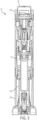
- FIGS. 1-3 illustrate a therapeutic agent delivery system 10 according to an embodiment of the present disclosure.
- the therapeutic agent delivery system 10 generally includes the profile of an auto-injector pen, although other profiles may alternatively be used.
- the therapeutic agent delivery system 10 includes a housing 12 that is elongated along a longitudinal axis 14.
- the housing 12 carries a therapeutic agent delivery assembly 16.
- the therapeutic agent delivery assembly 16 includes a therapeutic agent and a needle 18, and the therapeutic agent delivery assembly 16 translates relative to the housing 12 from a stowed configuration (as illustratively shown in FIGS.
- a configuration in which the needle 18 is disposed entirely within the housing 12) to a deployed configuration (shown elsewhere - for example, a configuration in which the needle 18 is at least partially exposed from the housing 12 and configured to engage the subject and deliver the therapeutic agent to the subject).
- the therapeutic agent delivery assembly 16 also translates relative to the housing 12 from the deployed configuration to a withdrawn configuration (shown elsewhere - for example, a configuration in which the needle 18 is disposed entirely within the therapeutic agent delivery system 10).
- a proximal end portion 20 of the therapeutic agent delivery system 10 includes a user input 22 (illustratively, a depressible button) that is actuated to actuate the therapeutic agent delivery assembly 16 (that is, move the needle 18 from the stowed configuration to the deployed configuration and deliver the therapeutic agent to the user).
- the therapeutic agent delivery system 10 normally inhibits the user input 22 from being actuated (stated another way, the user input 22 is normally "locked”).
- the therapeutic agent delivery system 10 further includes a sleeve 24 that is normally exposed at a distal end portion 26 of the system 10.
- the sleeve 24 is pressed against a surface (for example, the skin of a subject) to permit the user input 22 to be actuated (stated another way, to "unlock” the user input 22).
- the therapeutic agent delivery system 10 may then be actuated by pressing the user input 22.
- the needle 18 is translated to the withdrawn configuration and inhibited from being translated to the deployed configuration (stated another way, the system 10 is "locked out”).
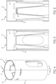
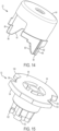
- FIGS. 4-6 illustrate a distal housing portion 28 of the housing 12.
- the distal housing portion 28 includes a main body 30 that has a generally cylindrical shape.
- the main body 30 includes an inner passageway 32 that carries other components of the therapeutic agent delivery system 10.
- the restraint feature includes two radially-inwardly extending tabs 36. As shown in FIG. 5 , the tabs 36 taper radially-inwardly proceeding toward the distal end portion 26 ( FIG. 1 ).
- the restraint features may be non-tapering tabs.
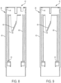
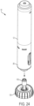
- FIGS. 7-9 illustrate a proximal housing portion 38 of the housing 12.
- the proximal housing portion 38 includes a main body 40 that has a generally cylindrical shape.
- the main body 40 includes an inner passageway 42 that carries other components of the therapeutic agent delivery system 10.
- an inner surface 44 of the proximal housing portion 38 Adjacent to the inner passageway 42, an inner surface 44 of the proximal housing portion 38 carries an actuation feature (illustratively, two helically extending ramps 46) that, as described in further detail below, selectively engage and facilitate actuating the therapeutic agent delivery assembly 16.
- the inner surface 44 of the proximal housing portion 38 carries a translation feature (illustratively, four axially extending ridges 48) that facilitates translation of the sleeve 24 in the inner passageway 42.
- the inner surface 44 also carries a biasing feature (illustratively, a radially-inwardly extending flange 50) that, as described in further detail below, engages a spring (shown elsewhere).
- the proximal housing portion 38 includes a coupling feature (illustratively, a plurality of snap connectors 52) for coupling to the distal housing portion 28. In other embodiments, different arrangements of the proximal housing portion 38 are possible. For example, the proximal housing portion 38 may be monolithically formed with the distal housing portion 28.
- FIGS. 10-12 illustrate the sleeve 24 of the therapeutic agent delivery system 10.
- the sleeve 24 is formed of a conductive material (for example, a metal) to facilitate, as described in further detail below, operatively coupling components of an electronics assembly (shown elsewhere) of the therapeutic agent delivery system 10.
- the sleeve 24 includes a distal sleeve portion 54 that has a generally cylindrical shape.
- the distal sleeve portion 54 includes an inner passageway 56 that carries components of the therapeutic agent delivery assembly 16.
- the distal sleeve portion 54 includes a restraint feature (illustratively, two radially-outwardly extending tabs 58) for selectively engaging the restraint feature of the distal housing portion 28 (illustratively, the two radially-inwardly extending and inwardly deflectable tabs 36) and, as described in further detail below, selectively inhibiting translation of the sleeve 24 relative to the distal housing portion 28. As shown in FIG. 11 , the tabs 58 taper radially-outwardly proceeding away from the distal end portion 26 ( FIG. 1 ).
- the distal sleeve portion 54 couples to two proximally and axially extending arms 60.
- the axially extending arms 60 carry a translation feature (illustratively, four axially extending ridges 62) that engage the translation feature of the proximal housing portion 38 (illustratively, the four axially extending ridges 48) to facilitate translation and inhibit rotation of the sleeve 24 within the housing 12.
- the axially extending arms 60 also define, together with the therapeutic agent delivery assembly 16, a cam and slot mechanism that facilitates rotation of the therapeutic agent delivery assembly 16 relative to the housing 12 upon translation of the sleeve 24 relative to the housing 12.
- the axially extending arms 60 each include a slot 64 of the cam and slot mechanism, and the slots 64 translatably receive cams of the therapeutic agent delivery assembly 16 (shown elsewhere).
- the slots 64 illustratively include a helically extending proximal slot portion 66 and an axially extending distal slot portion 68.
- the slots 64 of the axially extending arms 60 may have different shapes, or the axially extending arms 60 may include cams instead of slots.
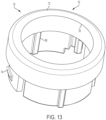
- FIG. 13 illustrates a user input support 70 of the therapeutic agent delivery system 10.
- the user input support 70 couples to the proximal housing portion 38 opposite the distal housing portion 28.
- the user input support 70 includes a main body 72, and the main body 72 carries a coupling feature (illustratively, a plurality of snap connectors 74) for coupling to the proximal housing portion 38.
- the main body 72 includes an inner passageway 76 in which the user input 22 is received.
- an inner surface 78 of the user input support 70 carries a translation feature (illustratively, a plurality of axially extending ridges 80) that facilitates translation of the user input 22 relative to the user input support 70.
- a translation feature illustrated as a plurality of axially extending ridges 80
- FIG. 14 illustrates the user input 22 of the therapeutic agent delivery system 10.
- the user input 22 includes a translation feature (illustratively, a plurality of axially extending channels 82) for engaging the translation feature of the user input support 70 (illustratively, the plurality of axially extending ridges 80) to facilitate translation of the user input 22 relative to the user input support 70 and the housing 12.
- a translation feature illustrated as, a plurality of axially extending channels 82
- the user input 22 Adjacent to the translation feature, the user input 22 includes an exposed portion 84 that is pressed by a user to translate the user input 22 relative to the user input support 70 and the housing 12.
- the user input 22 also includes an actuation feature that facilitates actuating the therapeutic agent delivery assembly 16.
- the actuation feature includes two arms 86 that are disposed opposite the exposed portion 84.
- Each of the arms 86 includes a restraint surface (illustratively, a circumferentially extending surface 88) and an actuation surface (illustratively, a helically extending surface 90). Interaction of the arms 86 with other components of the therapeutic agent delivery system 10 is described in further detail below. In other embodiments, different arrangements of the user input 22 are possible.
- FIG. 15 illustrates an input restraint 92 of the therapeutic agent delivery system 10.
- the input restraint 92 includes an actuation feature that is configured to interact with the actuation feature of the user input 22.
- the actuation feature of the input restraint 92 includes two partial flanges 94 and two openings 96 disposed between the partial flanges 94.
- Each of the partial flanges 94 includes a restraint surface (illustratively, a circumferentially extending surface 98) that, in certain situations and as described in further detail below, engages one of the restraint surfaces 88 of the user input 22 to inhibit translation of the user input 22 relative to the housing 12.
- Each of the partial flanges 94 also includes an actuation surface (illustratively, a rounded corner 100 adjacent to one of the openings 96) that, in certain situations, engages one of the actuation surfaces 90 of the user input 22 to facilitate rotating the input restraint 92 relative to the housing 12 upon translating the user input 22 relative to the housing 12.
- the input restraint 92 includes a detachable coupling feature (illustratively, a plurality of ledges 102 or radially-outwardly extending L-shaped protrusions 102) that detachably couples the input restraint 92 to the therapeutic agent delivery assembly 16. In other embodiments, different arrangements of the input restraint 92 are possible.
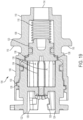
- FIG. 16-19 illustrate a pressure generating actuator 104 of the therapeutic agent delivery assembly 16.
- the pressure generating actuator 104 is actuated by the user input 22, via the input restraint 92, to facilitate mixing of internally-carried chemical reagents, which generates one or more pressurized fluids (for example, one or more gases). Examples of suitable reagents and generated gases are provided below.
- the pressurized fluid(s) are delivered to and facilitate movement of other components of the therapeutic agent delivery assembly 16.
- the pressure generating actuator 104 includes a first mixing chamber 106 and a second mixing chamber 108, which are illustratively monolithically formed with each other.
- the mixing chambers 106, 108 include an outlet coupling feature (illustratively, an externally threaded surface 112) for coupling to another component of the therapeutic agent delivery assembly 16.
- the outlet end portion 110 also includes an actuator outlet 114 through which pressurized fluid is discharged from the pressure generating actuator 104.
- the mixing chambers 106, 108 also define, together with the sleeve 24, the cam and slot mechanism.
- the mixing chambers 106, 108 carry radially-outwardly extending fingers or cams 116 of the cam and slot mechanism, and the cams 116 are translatably received in the slots 64 of the sleeve 24.
- mixing chambers 106, 108 may include slots instead of cams.
- the mixing chambers 106, 108 carry an actuator spring 118, a mixing piston 120, and a rotatable shuttle 122 in an axially stacked arrangement.
- the rotatable shuttle 122 includes a recess 124, and the recess 124 carries a detachable coupling feature (illustratively, a plurality of ledges 126 or radially-outwardly extending L-shaped protrusions 126) that engages the detachable coupling feature of the input restraint 92 (illustratively, the plurality of ledges 102).
- the first mixing chamber 106 and the shuttle 122 form a helical coupling for movably coupling to each other.
- the shuttle 122 includes a helically extending ridge 128 and the first mixing chamber 106 includes a helically extending groove 130 that receives the ridge 128.
- the shuttle 122 includes an actuation feature (illustratively, two radially-outwardly extending fingers 132) that, as described in further detail below, engage and are driven by the actuation feature of the proximal housing portion 38 (illustratively, the two helically extending ramps 46).
- the shuttle 122 includes a first restraining feature (illustratively, eight radially-inwardly extending tabs 134) that engages the mixing piston 120.
- the shuttle 122 also includes channels 136 disposed between adjacent tabs 134.
- the mixing piston 120 includes a second restraining feature (illustratively, eight radially-outwardly extending tabs 138) that engages the first restraining feature of the shuttle 122.
- the first restraining feature engages the second restraining feature (illustratively, the radially-inwardly extending tabs 134 of the shuttle 122 are angularly aligned with and engage the radially-outwardly extending tabs 138 of the mixing piston 120) to hold the mixing piston 120 in a position between the first mixing chamber 106 and the second mixing chamber 108.
- the mixing piston 120 thereby maintains separation of reagents in the first mixing chamber 106 and the second mixing chamber 108.
- the actuator spring 118 is also compressed within the second mixing chamber 108 against the mixing piston 120.
- the shuttle 122 rotates relative to the first mixing chamber 106 and the second mixing chamber 108 to disengage the first restraining feature from the second restraining feature (illustratively, the radially-inwardly extending tabs 134 of the shuttle 122 are angularly misaligned with, or angularly offset from, the radially-outwardly extending tabs 138 of the mixing piston 120, and the channels 136 are angularly aligned with the radially-outwardly extending tabs 138 of the mixing piston 120).
- the actuator spring 118 expands and moves the mixing piston 120 into the shuttle 122 and the first mixing chamber 106, which permits the reagents in the first mixing chamber 106 and the second mixing chamber 108 to mix.
- Mixing of the reagents generates one or more pressurized fluids (for example, one or more gases), and the pressurized fluid(s) are delivered to other components of the therapeutic agent delivery assembly 16.
- the reagents may mix in only first mixing chamber 106 or in both mixing chambers 106, 108.
- pressure generating actuators 104 have different structures.
- suitable pressure generating actuators 104 include those described in: U.S. Patent No. 9,795,740 titled “Chemical Engines and Methods for Their Use, Especially in the Injection of Highly Viscous Fluids”; International PCT Application No. PCT/US2018/017547 , titled “Processes and Devices for Delivery of Fluid by Chemical Reaction” and filed February 9, 2018; and International PCT Application No. PCT/US2018/049048 , titled “System for Controlling Gas Generation with a Drug Delivery Device” and filed on August 31, 2018.
- Any suitable chemical reagent or reagents can be used to generate one or more pressurized fluids in pressure generating actuators 104 of the present disclosure.
- generated gases include carbon dioxide gas, nitrogen gas, oxygen gas, chlorine gas, etc.
- the generated gas is inert and non-flammable.
- the amount of gas needed to facilitate movement of other components of the therapeutic agent delivery assembly 16 may impact the type, amount, and concentration of each reagent used in pressure generating actuators 104.
- the reagents may be in dry form (for example, powdered form, tablet form, and/or low-density freeze-dried solid form) and/or in liquid form (for example, a solution, colloid, or stable or non-stable suspension).
- a bicarbonate (which may be present in dry form) reacts with an acid (which may be present in liquid form) to produce carbon dioxide gas in pressure generating actuators 104.
- suitable bicarbonates include sodium bicarbonate, potassium bicarbonate, and ammonium bicarbonate.
- Other ingredients may also be present along with the bicarbonates, such as diatomaceous earth.
- suitable acids include acetic acid, citric acid, potassium bitartrate, disodium pyrophosphate, and calcium dihydrogen phosphate.
- the bicarbonate is potassium bicarbonate and the acid is aqueous citric acid, which may react to produce carbon dioxide gas and a liquid mixture of water and dissolved potassium citrate.
- a metal carbonate such as copper carbonate or calcium carbonate
- a metal oxide such as copper carbonate or calcium carbonate
- AIBN 2,2'-azobisisobutyronitrile
- enzymes for example yeast
- Some substances readily sublime, going from solid to gas. Such substances include but are not limited to naphthalene and iodine.
- hydrogen peroxide is decomposed with catalysts such as enzymes (for example catalase) or manganese dioxide to produce oxygen gas in pressure generating actuators 104.
- catalysts such as enzymes (for example catalase) or manganese dioxide to produce oxygen gas in pressure generating actuators 104.
- silver chloride is decomposed through exposure to light to generate a gas in pressure generating actuators 104. Suitable reagents, chemical formulations, and reactions are further described in U.S. Patent No. 9,795,740 , International PCT Application No. PCT/US2018/017547 , and International PCT Application No. PCT/US2018/049048 .
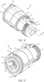
- FIGS. 20-21 illustrate a syringe assembly 140 of the therapeutic agent delivery assembly 16.
- the syringe assembly 140 includes an inlet portion 142, and the inlet portion 142 includes an inlet coupling feature (illustratively, an internally threaded surface 144) that couples to the outlet coupling feature of the pressure generating actuator 104 (illustratively, the externally threaded surface 112).
- the inlet portion 142 also includes an inlet 146 that receives pressurized fluid(s) from the outlet 114 of the pressure generating actuator 104.
- the inlet portion 142 couples to a syringe chamber 148, and the syringe chamber 148 includes a syringe passageway 150 that receives the pressurized fluid(s) from the inlet portion 142.
- the syringe passageway 150 carries a syringe piston 152, and the syringe piston 152 translates away from the inlet portion 142 and towards an outlet portion 154 of the syringe assembly 140 when the syringe passageway 150 receives the pressurized fluid(s).
- the syringe piston 152 carries a magnetic component 156 that facilitates determining the position of the syringe piston 152 in the syringe passageway 150.
- the syringe passageway 150 also carries a therapeutic agent (illustratively, 2.25mL of the therapeutic agent, although other suitable volumes, including, for example, 2.08 mL, 1.08 mL, or 0.58 mL may alternatively be carried) between the syringe piston 152 and the outlet portion 154, more specifically the needle 18.
- a therapeutic agent illustrated in the therapeutic agent, although other suitable volumes, including, for example, 2.08 mL, 1.08 mL, or 0.58 mL may alternatively be carried
- translation of the syringe piston 152 in the syringe passageway 150 causes the needle 18 to discharge the therapeutic agent therefrom.
- the inlet portion 142 and the syringe chamber 148 may be monolithically formed with each other, or the syringe assembly 140 could be replaced
- FIGS. 22-23 illustrate an electronics assembly 158 of the therapeutic agent delivery system 10.
- the electronics assembly 158 includes an electronic controller 160 that is operatively coupled to and receives power from a power supply 162 (illustratively, a battery).
- the controller 160 is operatively coupled to a sleeve sensor 164 that determines if the sleeve 24 has been translated relative to the housing 12 and the user input 22 is thereby "unlocked” (illustratively, two electrical contacts 166 that engage the sleeve 24 and thereby close a circuit when the sleeve 24 translates relative to the housing 12).
- the controller 160 is operatively coupled to an indicator device 168 (including, for example, visual and/or audible indicators) that indicates the status of the system 10 (for example, that the sleeve 24 has been translated relative to the housing 12 and the user input 22 is thereby unlocked).
- the controller 160 is operatively coupled to a user input sensor 169 (illustratively, an electrical switch 170) that determines if the user input 22 has been actuated.
- the indictor device 210 may provide an indication (for example, a visual and/or audible indication) if the user input 22 has been actuated.
- the controller 160 is operatively coupled to a piston sensor 172 that is configured to determine the position of the syringe piston 152 in the syringe chamber 148 (for example, to determine if the syringe piston 152 has been moved toward the syringe outlet portion 154, thereby indicating that the therapeutic agent has been discharged from the needle 18).
- the piston sensor 172 is a hall effect sensor 174 that is configured to sense the magnetic component 156 carried by the syringe piston 152.
- the piston sensor 172 may be an optical sensor.
- the indictor device 210 may provide an indication (for example, a visual and/or audible indication) if the magnetic component 156 and the syringe piston 152 have been moved toward the syringe outlet portion 154.
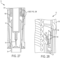
- FIGS. 25-28 illustrate the therapeutic agent delivery system 10 in a first configuration (which may also be referred to as a "locked" configuration).
- the sleeve 24 is disposed in an exposed configuration (that is, the sleeve 24 partially extends from the distal housing portion 28), and an extension spring 180 compressed between the sleeve 24 and the proximal housing portion 38 (see FIGS. 27 and 28 ) urges the sleeve 24 to remain in the exposed configuration.
- an extension spring 180 compressed between the sleeve 24 and the proximal housing portion 38
- the cams 116 of the pressure generating actuator 104 are disposed in the proximal slot portions 66 of the sleeve 24.
- the input restraint 92 is disposed in a first rotational configuration relative to the user input 22 and the housing 12.
- the input restraint 92 inhibits actuation of the user input 22 due to contact between the restraint surfaces 98 of the input restraint 92 and the restraint surfaces 88 of the user input 22.
- the therapeutic agent delivery assembly 16 is disposed in the stowed configuration (illustratively, a configuration in which the needle 18 is disposed entirely within the housing 12).
- the sleeve 24 is disposed apart from the electrical contacts 166.
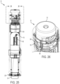
- FIGS. 29-30 illustrate the therapeutic agent delivery system 10 in a second configuration (which may also be referred to as an "unlocked" configuration).
- the therapeutic agent delivery system 10 moves from the first configuration to the second configuration upon pushing or pressing the sleeve 24 into a surface (for example, the skin of a subject) and translating the sleeve 24 relative to the housing 12 from the exposed configuration to a retracted configuration (illustratively, a configuration in which the sleeve 24 is disposed entirely within the housing 12).
- a retracted configuration illustrated specifically in FIGS. 29 and 30 , translating the sleeve 24 from the exposed configuration to the retracted configuration causes relative movement of the cams 116 of the pressure generating actuator 104 and the slots 64 of the sleeve 24.
- the cams 116 translate in the helically extending proximal portions 66 of the slots 64. This translation causes the pressure generating actuator 104, a deployment spring 182 compressed between the pressure generating actuator 104 and the input restraint 92, and the input restraint 92 to rotate relative to the housing 12 from the first rotational configuration to a second rotational configuration.
- the sleeve 24 engages the electrical contacts 166 and thereby closes a circuit.
- the indicator device 168 may provide an indication (for example, visual and/or audible indications).
- the therapeutic agent delivery system 10 may be returned to the first configuration by moving the therapeutic agent delivery system 10 apart from the surface (more specifically, by permitting the extension spring 180 to expand and move the sleeve 24 to the exposed configuration).
- the restraint surfaces 98 of the input restraint 92 are angularly misaligned with the restraint surfaces 88 of the user input 22, and the openings 96 of the input restraint 92 are angularly aligned with the restraint surfaces 88 of the user input 22.
- the user input 22 may be actuated (illustratively, by translating the user input 22 relative to the housing 12 in a direction that is substantially parallel to the longitudinal axis 14 (that is, parallel ⁇ 5 degrees)), which causes the actuation surfaces 90 of the user input 22 to engage the actuation surfaces 100 of the input restraint 92.
- the user input 22 thereby rotates the input restraint 92 from the second rotational configuration to a third rotational configuration, which causes, as shown specifically in FIG. 34 , the ledges 102 of the input restraint 92 to slide over and disengage the ledges 126 of the shuttle 122.
- the user input 22 may also actuate the switch 170, and the indicator device 168 may provide an indication (for example, visual and/or audible indications).
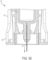
- the deployment spring 182 is relatively unconstrained upon disengagement of the input restraint 92 and the shuttle 122. As such, the deployment spring 182 expands and pushes the therapeutic agent delivery assembly 16 distally relative to the housing 12. As shown in FIG. 36 , the therapeutic agent delivery assembly 16 thereby moves from the stowed configuration to the deployed configuration (illustratively, a configuration in which the needle 18 is partially exposed at the distal end portion 26 of the housing 12 and configured to engage the subject and deliver the therapeutic agent to the subject). Illustratively, the needle 18 translates from the stowed configuration to the deployed configuration in a direction that is substantially parallel to the longitudinal axis 14 (that is, parallel ⁇ 5 degrees). Referring again to FIG.
- translation of the therapeutic agent delivery assembly 16 distally relative to the housing 12 also causes the radially-outwardly extending fingers 132 of the shuttle 122 to engage and slide over the helically extending ramps 46 of the proximal housing portion 38.
- This engagement causes the shuttle 122 to rotate relative to the mixing chambers 106, 108 of the pressure generating actuator 104 (illustratively, about an axis that is substantially parallel to the longitudinal axis 14 (that is, parallel ⁇ 5 degrees)), which actuates the pressure generating actuator 104. More specifically and as illustrated in FIG.
- the rotating the shuttle 122 relative to the first and second mixing chambers 106, 108 angularly misaligns the radially-inwardly extending tabs 134 of the shuttle 122 with the radially-outwardly extending tabs 138 of the mixing piston 120 and angularly aligns the channels 136 of the shuttle 122 with the radially-outwardly extending tabs 138 of the mixing piston 120.
- the actuator spring 118 is relatively unconstrained and, as shown in FIG. 38 , the actuator spring 118 expands and translates the mixing piston 120 into the shuttle 122 and the first mixing chamber 106.
- the reagents in the first mixing chamber 106 and the second mixing chamber 108 then mix and react to provide a pressurized gas, which the pressure generating actuator 104 delivers from the actuator outlet 114.
- the pressure generating actuator 104 delivers the pressurized gas to the syringe passageway 150, which translates the syringe piston 152 distally within the syringe passageway 150.
- the syringe piston 152 pushes the therapeutic agent distally to the needle 18, and the needle 18 discharges the therapeutic fluid and delivers the therapeutic fluid to the subject.
- the piston sensor 172 may sense that the magnetic component 156, and the syringe piston 152, are disposed near the outlet portion 154 of the syringe assembly 140, and the indicator device 168 may provide an indication (for example, visual and/or audible indications).
- the user may stop pressing the therapeutic agent delivery system 10 against the surface.
- the extension spring 180 is relatively unconstrained and expands to translate the housing 12 and the therapeutic agent delivery assembly 16 proximally relative to the sleeve 24.
- the needle 18 is thereby disposed in the withdrawn configuration (illustratively, a configuration in which the needle 18 is disposed entirely within the sleeve 24). As shown specifically in FIG.
- the radially-inwardly extending tabs 36 of the distal housing portion 28 and the radially-outwardly extending tabs 58 of the sleeve 24 engage and slide over each other to inhibit the housing 12 and the therapeutic agent delivery assembly 16 from translating distally relative to the sleeve 24 (that is, the therapeutic agent delivery system 10 may be "locked out”). The therapeutic agent delivery system 10 may then be discarded.
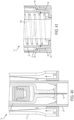
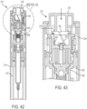
- FIGS. 42-47 illustrate a therapeutic agent delivery system 210 according to another embodiment of the present disclosure.
- the therapeutic agent delivery system 210 has the same structure as the therapeutic agent delivery system 10, except as described below.
- the therapeutic agent delivery system 210 is moved from a first configuration to a second configuration (which may also be referred to as an "unlocked" configuration) by pressing a sleeve 212 into a surface (for example, the skin of a subject) and translating the sleeve 212 proximally relative to a housing 214. Then, a user input 218 may be translated distally to actuate the device. More specifically and as shown in FIG.
- radially-outwardly extending tabs 216 of the user input 218 engage and slide over helically extending ramps 220 formed in a recess 222 of an actuator shuttle 224 of a pressure generating actuator 226.
- the actuator shuttle 224 thereby rotates relative to an actuator mixing chamber 228 of the pressure generating actuator 226, and the pressure generating actuator 226 is actuated in the same manner as the pressure generating actuator 104 described above.
- the pressure generating actuator 226 delivers pressurized gas to an inner passageway 230 of an actuator coupling 232.
- the pressurized gas pushes an intermediate piston 234 and a syringe assembly 236 distally, and a needle 238 thereby moves from a stowed configuration to a deployed configuration.
- the pressurized gas pushes a syringe piston 240 distally within a syringe chamber 242.
- the syringe chamber 242 carries a therapeutic agent opposite the pressure generating actuator 226, and distal movement of the syringe piston 240 causes the syringe chamber 242 to deliver the therapeutic agent to the needle 238, and the needle 238 thereby discharges the therapeutic agent.
- the needle 238 may then be moved to a withdrawn configuration and the therapeutic agent delivery system 210 may then be locked out in the same manner as the therapeutic agent delivery system 10 described above.
- the therapeutic agent delivery system 210 may then be discarded.
Landscapes
- Health & Medical Sciences (AREA)
- Vascular Medicine (AREA)
- Engineering & Computer Science (AREA)
- Anesthesiology (AREA)
- Biomedical Technology (AREA)
- Heart & Thoracic Surgery (AREA)
- Hematology (AREA)
- Life Sciences & Earth Sciences (AREA)
- Animal Behavior & Ethology (AREA)
- General Health & Medical Sciences (AREA)
- Public Health (AREA)
- Veterinary Medicine (AREA)
- Infusion, Injection, And Reservoir Apparatuses (AREA)
Claims (12)
- System zur Abgabe therapeutischer Mittel (10, 210), umfassend:ein Gehäuse (12, 214), das einen distalen Endabschnitt (26) aufweist;eine Baugruppe zur Abgabe therapeutischer Mittel (16), die von dem Gehäuse (12, 214) getragen wird, die Baugruppe zur Abgabe therapeutischer Mittel (16) umfassend:eine Kammer (148, 242), umfassend einen Durchgang (150);ein therapeutisches Mittel, das in dem Durchgang (150) transportiert wird;eine Nadel (18, 238), die mit dem Durchgang (150) kommuniziert;die Baugruppe zur Abgabe therapeutischer Mittel (16) relativ zum Gehäuse (12, 214) von einer verstauten Konfiguration in eine entfaltete Konfiguration verschiebbar ist, wobei sich die Nadel (18, 238) in der entfalteten Konfiguration mindestens teilweise distal vom distalen Endabschnitt (26) des Gehäuses (12, 214) erstreckt;eine Benutzereingabe (22, 218), die so konfiguriert ist, dass sie von einem Benutzer betätigt werden kann, wobei die Betätigung der Benutzereingabe (22, 218) die Baugruppe zur Abgabe therapeutischer Mittel (16) von der verstauten Konfiguration in die entfaltete Konfiguration überführt;eine Eingabehalterung (92), die relativ zum Gehäuse (12, 214) von einer ersten Rotationskonfiguration zu einer zweiten Rotationskonfiguration drehbar ist, wobei in der ersten Rotationskonfiguration die Eingabehalterung (92) die Betätigung der Benutzereingabe (22, 218) verhindert und in der zweiten Rotationskonfiguration die Eingabehalterung (92) die Betätigung der Benutzereingabe (22, 218) zulässt; undeine Hülse (24, 212), die relativ zum Gehäuse (12, 214) aus einer freiliegenden Konfiguration in eine zurückgezogene Konfiguration verschiebbar ist, wobei sich die Hülse (24, 212) in der freiliegenden Konfiguration mindestens teilweise distal vom distalen Endabschnitt (26) des Gehäuses (12, 214) erstreckt und die Hülse (24, 212) die Eingabehalterung (92) aus der ersten Rotationskonfiguration in die zweite Rotationskonfiguration dreht, wenn sie aus der freiliegenden Konfiguration in die zurückgezogene Konfiguration verschoben wird;wobei die Baugruppe zur Abgabe therapeutischer Mittel (16) ferner einen druckerzeugenden Aktuator (104) umfasst, wobei die Betätigung der Benutzereingabe (22, 218) den druckerzeugenden Aktuator (104) veranlasst, das therapeutische Mittel unter Druck zu setzen, das therapeutische Mittel aus dem Durchgang (150) an die Nadel (18, 238) abzugeben und das therapeutische Mittel aus der Nadel (18, 238) auszustoßen; undwobei der druckerzeugende Aktuator (104) eine Mischkammer (106, 108) und ein von der Mischkammer (106, 108) getragenes Shuttle (122) umfasst, und der druckerzeugende Aktuator (104) das therapeutische Mittel bei der Rotation des Shuttles (122) relativ zur Mischkammer (106, 108) unter Druck setzt.
- System zur Abgabe therapeutischer Mittel (10, 210) nach Anspruch 1, ferner umfassend einen Nocken- und Schlitzmechanismus (64, 116), der die Eingabehalterung (92) mit der Hülse (24, 212) koppelt, wobei der Nocken- und Schlitzmechanismus (64, 116) bewirkt, dass sich die Eingabehalterung (92) von der ersten Rotationskonfiguration in die zweite Rotationskonfiguration dreht, wenn sich die Hülse (24, 212) von der exponierten Konfiguration in die zurückgezogene Konfiguration bewegt.
- System zur Abgabe therapeutischer Mittel (10, 210) nach Anspruch 2, wobei der Nocken- und Schlitzmechanismus (64, 116) einen Schlitz (64) und einen in dem Schlitz (64) gleitend aufgenommenen Nocken (116) umfasst, die Hülse (24, 212) den Schlitz (64) umfasst und die Eingabehalterung (92) mit dem Nocken (116) gekoppelt ist.
- System zur Abgabe therapeutischer Mittel (10, 210) nach einem der Ansprüche 1 bis 3, wobei das Gehäuse (12, 214) eine Längsachse (14) definiert und die Nadel (18, 238) von der verstauten Konfiguration in die entfaltete Konfiguration in einer Entfaltungsrichtung im Wesentlichen parallel zur Längsachse (14) bewegt wird.
- System zur Abgabe therapeutischer Mittel (10, 210) nach Anspruch 4, wobei die Eingabehalterung (92) von der ersten Rotationskonfiguration in die zweite Rotationskonfiguration um eine Rotationsachse rotiert, die im Wesentlichen parallel zur Längsachse (14) verläuft.
- System zur Abgabe therapeutischer Mittel (10, 210) nach einem der Ansprüche 4 und 5, wobei die Benutzereingabe (22, 218) so konfiguriert ist, dass sie in einer Betätigungsrichtung im Wesentlichen parallel zur Längsachse (14) betätigt wird.
- System zur Abgabe therapeutischer Mittel (10, 210) nach einem der Ansprüche 1 bis 6, ferner umfassend eine Feder (180), die die Hülse (24, 212) in Richtung der exponierten Konfiguration drückt.
- System zur Abgabe therapeutischer Mittel (10, 210) nach einem der Ansprüche 1 bis 7, wobei das Gehäuse (12, 214) ferner einen proximalen Endabschnitt (20) gegenüber dem distalen Endabschnitt (26) umfasst, wobei sich die Benutzereingabe (22, 218) proximal vom proximalen Endabschnitt (20) des Gehäuses (12, 214) erstreckt.
- System zur Abgabe therapeutischer Mittel (10, 210) nach Anspruch 1, wobei:die freiliegende Konfiguration eine verriegelte Konfiguration ist, in der sich die Hülse (24, 212) mindestens teilweise distal von dem distalen Endabschnitt (26) des Gehäuses (12, 214) erstreckt;die zurückgezogene Konfiguration eine entriegelte Konfiguration ist, in der die Hülse (24, 212) in den distalen Endabschnitt (26) des Gehäuses (12, 214) gedrückt wird;und ferner eine betätigte Konfiguration umfasst, in der ein unter Druck stehendes Fluid aus dem druckerzeugenden Aktuator (104) die Abgabe des therapeutischen Mittels aus dem Durchgang (150) an die Nadel (18, 238) und die Abgabe des therapeutischen Mittels aus der Nadel (18, 238) bewirkt.
- System zur Abgabe therapeutischer Mittel (10, 210) nach Anspruch 9, wobei
die Eingabehalterung (92) die Betätigung der Benutzereingabe (22, 218) in der gesperrten Konfiguration verhindert und die Betätigung der Benutzereingabe (22, 218) in der entsperrten Konfiguration erlaubt. - System zur Abgabe therapeutischer Mittel (10, 210) nach einem der Ansprüche 9 und 10, ferner umfassend:eine Zugfeder (180), die die Hülse (24, 212) in die verriegelte Konfiguration drückt; undeine Entfaltungsfeder (182), die die Nadel (18, 238) in die entfaltete Konfiguration drückt.
- System zur Abgabe von therapeutischen Mitteln (10, 210) nach einem der Ansprüche 9 bis 11, das ferner ein Medikament umfasst.
Priority Applications (1)
| Application Number | Priority Date | Filing Date | Title |
|---|---|---|---|
| EP24184925.6A EP4414008A3 (de) | 2018-12-19 | 2019-12-12 | Vorrichtungen und verfahren zur abgabe von therapeutischen flüssigkeiten |
Applications Claiming Priority (2)
| Application Number | Priority Date | Filing Date | Title |
|---|---|---|---|
| US201862781662P | 2018-12-19 | 2018-12-19 | |
| PCT/US2019/065904 WO2020131552A1 (en) | 2018-12-19 | 2019-12-12 | Devices and processes for delivery of therapeutic fluids |
Related Child Applications (2)
| Application Number | Title | Priority Date | Filing Date |
|---|---|---|---|
| EP24184925.6A Division EP4414008A3 (de) | 2018-12-19 | 2019-12-12 | Vorrichtungen und verfahren zur abgabe von therapeutischen flüssigkeiten |
| EP24184925.6A Division-Into EP4414008A3 (de) | 2018-12-19 | 2019-12-12 | Vorrichtungen und verfahren zur abgabe von therapeutischen flüssigkeiten |
Publications (2)
| Publication Number | Publication Date |
|---|---|
| EP3897779A1 EP3897779A1 (de) | 2021-10-27 |
| EP3897779B1 true EP3897779B1 (de) | 2024-08-07 |
Family
ID=69143693
Family Applications (2)
| Application Number | Title | Priority Date | Filing Date |
|---|---|---|---|
| EP19832809.8A Active EP3897779B1 (de) | 2018-12-19 | 2019-12-12 | Vorrichtungen und verfahren zur abgabe therapeutischer flüssigkeiten |
| EP24184925.6A Pending EP4414008A3 (de) | 2018-12-19 | 2019-12-12 | Vorrichtungen und verfahren zur abgabe von therapeutischen flüssigkeiten |
Family Applications After (1)
| Application Number | Title | Priority Date | Filing Date |
|---|---|---|---|
| EP24184925.6A Pending EP4414008A3 (de) | 2018-12-19 | 2019-12-12 | Vorrichtungen und verfahren zur abgabe von therapeutischen flüssigkeiten |
Country Status (8)
| Country | Link |
|---|---|
| US (1) | US12420018B2 (de) |
| EP (2) | EP3897779B1 (de) |
| JP (1) | JP7222097B2 (de) |
| CN (1) | CN113164681B (de) |
| AU (1) | AU2019401422B2 (de) |
| CA (1) | CA3123210A1 (de) |
| ES (1) | ES2987026T3 (de) |
| WO (1) | WO2020131552A1 (de) |
Families Citing this family (7)
| Publication number | Priority date | Publication date | Assignee | Title |
|---|---|---|---|---|
| EP4210789B1 (de) | 2020-09-11 | 2026-03-11 | Eli Lilly and Company | Vorrichtungen und verfahren zur abgabe von therapeutischen flüssigkeiten |
| WO2022055758A1 (en) * | 2020-09-11 | 2022-03-17 | Eli Lilly And Company | Devices and processes for delivery of therapeutic fluids |
| WO2022055759A1 (en) * | 2020-09-11 | 2022-03-17 | Eli Lilly And Company | Devices and processes for delivery of therapeutic fluids |
| US20240307623A1 (en) * | 2021-07-22 | 2024-09-19 | Shl Medical Ag | A subassembly of a medicament delivery device |
| KR102599610B1 (ko) * | 2021-08-12 | 2023-11-08 | 김용현 | 약액 주입 장치 |
| IL310641A (en) * | 2021-08-19 | 2024-04-01 | Lilly Co Eli | Therapeutic agent delivery device including disposable and reusable portions |
| US20250001089A1 (en) * | 2021-08-20 | 2025-01-02 | Eli Lilly And Company | Therapeutic agent delivery device with user input |
Citations (1)
| Publication number | Priority date | Publication date | Assignee | Title |
|---|---|---|---|---|
| EP2624884B1 (de) * | 2010-10-08 | 2018-05-16 | Sanofi-Aventis Deutschland GmbH | Automatischer injector mit torsionsfeder |
Family Cites Families (127)
| Publication number | Priority date | Publication date | Assignee | Title |
|---|---|---|---|---|
| US2390246A (en) | 1940-10-18 | 1945-12-04 | Marvin L Folkman | Syringe |
| US2446429A (en) | 1944-10-20 | 1948-08-03 | Gen Electric | Cellular phenolic resin |
| US2833745A (en) | 1953-06-24 | 1958-05-06 | Basf Ag | Production of the salts of polymerized alpha.beta-unsaturated aliphatic acids |
| US2923243A (en) | 1958-03-24 | 1960-02-02 | Palmer Chemical & Equipment Co | Projectile for liquid drug delivery to animals |
| US3380831A (en) | 1964-05-26 | 1968-04-30 | Du Pont | Photopolymerizable compositions and elements |
| US3467526A (en) | 1965-02-19 | 1969-09-16 | Gen Foods Corp | Process for producing a supersaturated solution of carbon dioxide |
| US3405845A (en) | 1966-12-23 | 1968-10-15 | Products Res And Chemical Corp | Gas generating dispenser |
| US3556803A (en) | 1967-02-15 | 1971-01-19 | Dynatech Corp | Method of making a carbonated composition |
| JPS501700B1 (de) | 1969-06-21 | 1975-01-21 | ||
| US3773111A (en) | 1971-04-05 | 1973-11-20 | B Dunn | Fire extinguishing apparatus |
| US3968796A (en) | 1974-09-23 | 1976-07-13 | Thomas G. Lutes | Dental syringe |
| US4031889A (en) | 1975-03-25 | 1977-06-28 | William Floyd Pike | Power operated aspirating hypodermic syringe |
| US4203441A (en) | 1978-12-18 | 1980-05-20 | Alza Corporation | Osmotically triggered device with gas generating means |
| GB8416565D0 (en) | 1984-06-29 | 1984-08-01 | Hoechst Uk Ltd | Antibacterial derivatives |
| US4675174A (en) | 1985-08-16 | 1987-06-23 | Alza Corporation | Veterinary dispenser delivering beneficial agent by gas power generated in situ |
| US4744786A (en) | 1986-06-17 | 1988-05-17 | Cordis Corporation | Infusion pump |
| US4785972A (en) | 1987-07-14 | 1988-11-22 | Adolph Coors Company | Pressure generating system for a disposable container |
| DE3809482A1 (de) | 1988-03-22 | 1989-10-19 | Igor Groza | Injektionsinstrument |
| US5062834A (en) | 1989-02-24 | 1991-11-05 | Product Development (S.G.Z.) Ltd | Device for dispensing a liquid particularly useful for delivering medicaments at a predetermined rate |
| US5034114A (en) | 1989-07-28 | 1991-07-23 | Ira Kukin | Acid neutralizing combustion additive with detergent builder |
| JP3025843B2 (ja) | 1989-08-14 | 2000-03-27 | 武田薬品工業株式会社 | 注射針キャップ |
| US5151093A (en) | 1990-10-29 | 1992-09-29 | Alza Corporation | Osmotically driven syringe with programmable agent delivery |
| EP0581795B1 (de) | 1991-04-24 | 1998-08-26 | ORLITZKY, Anton | Gasgenerator |
| US5167641A (en) | 1991-05-29 | 1992-12-01 | Arnis, Inc. | Auto-retracting needle injector system |
| US5304128A (en) | 1992-09-22 | 1994-04-19 | Habley Medical Technology Corporation | Gas powered self contained syringe |
| DK39293D0 (da) | 1993-04-01 | 1993-04-01 | Novo Nordisk As | Dispenser sikret mod genbrug |
| AU7085594A (en) | 1993-07-02 | 1995-01-24 | Ji Hoon Park | Syringe |
| US5398850A (en) | 1993-08-06 | 1995-03-21 | River Medical, Inc. | Gas delivery apparatus for infusion |
| US5540665A (en) | 1994-01-31 | 1996-07-30 | Alza Corporation | Gas driven dispensing device and gas generating engine therefor |
| US5478316A (en) | 1994-02-02 | 1995-12-26 | Becton, Dickinson And Company | Automatic self-injection device |
| US5518145A (en) | 1994-09-12 | 1996-05-21 | Chen; Hsi H. | Glue injector and the process of injection |
| WO1996041159A1 (en) | 1995-06-07 | 1996-12-19 | Ceramatec, Inc. | Gas amplifier |
| US5700245A (en) | 1995-07-13 | 1997-12-23 | Winfield Medical | Apparatus for the generation of gas pressure for controlled fluid delivery |
| AU7093096A (en) | 1995-09-05 | 1997-03-27 | Elan Medical Technologies Limited | Chemically driven liquid delivery pumping device |
| US5645824A (en) | 1995-10-02 | 1997-07-08 | Lim; Min H. | Color changing reagent composition for coating on needles used in medical applications |
| ZA9610374B (en) | 1995-12-11 | 1997-06-23 | Elan Med Tech | Cartridge-based drug delivery device |
| GB9602605D0 (en) | 1996-02-09 | 1996-04-10 | Weston Medical Ltd | Injection aid |
| CA2200030C (en) | 1996-03-15 | 2006-04-25 | Seiji Ohtani | Syringe |
| US5992700A (en) | 1997-05-28 | 1999-11-30 | Apex Medical Technologies, Inc. | Controlled gas generation for gas-driven infusion devices |
| US6500150B1 (en) | 1997-06-16 | 2002-12-31 | Elan Pharma International Limited | Pre-filled drug-delivery device and method of manufacture and assembly of same |
| US5971722A (en) | 1997-09-05 | 1999-10-26 | Baxter International Inc | Electrochemical syringe pump having a sealed storage reservoir for a charge transfer medium |
| US5941857A (en) | 1997-09-12 | 1999-08-24 | Becton Dickinson And Company | Disposable pen needle |
| IE970782A1 (en) | 1997-10-22 | 1999-05-05 | Elan Corp | An improved automatic syringe |
| EP1082151A1 (de) | 1998-06-04 | 2001-03-14 | ELAN CORPORATION, Plc | Gasbetriebene medikamentenabgabevorrichtung |
| SE9803662D0 (sv) | 1998-10-26 | 1998-10-26 | Pharmacia & Upjohn Ab | Autoinjector |
| US6406455B1 (en) | 1998-12-18 | 2002-06-18 | Biovalve Technologies, Inc. | Injection devices |
| US6086569A (en) | 1999-05-04 | 2000-07-11 | Schweizer; Kenneth M. | Hypodermic syringe |
| US20010027293A1 (en) | 1999-06-29 | 2001-10-04 | Ashok V. Joshi | Storage stable fluid injection device and associated process |
| US6601584B2 (en) | 1999-09-17 | 2003-08-05 | Pi Medical, Inc. | Contracting snoring treatment implant |
| US6086568A (en) | 1999-10-15 | 2000-07-11 | Becton Dickinson And Company | Syringe plunger rod for retracting needle syringe |
| FR2802103B1 (fr) | 1999-12-08 | 2003-10-03 | Poudres & Explosifs Ste Nale | Seringue sans aiguille fonctionnant avec entrainement du principe actif par effet tube a choc |
| EP2308549A1 (de) | 2000-07-22 | 2011-04-13 | E-WHA Fresenius Kabi Inc. | Verschlusskappe mit Entlüftung |
| US6431468B1 (en) | 2000-11-06 | 2002-08-13 | Flexible Products Company | Safety mechanism for dispensing apparatus |
| US6575961B2 (en) | 2001-02-20 | 2003-06-10 | Microlin, L.C. | Fluid delivery device and associated method |
| WO2003039634A1 (en) | 2001-11-09 | 2003-05-15 | Alza Corporation | Pneumatic powered autoinjector |
| KR100456273B1 (ko) | 2001-11-16 | 2004-11-10 | 김용년 | 산과 반응하여 일정 속도로 이산화탄소를 발생시킬 수있는 고상 제제 및 그의 제조 방법 |
| JP3993169B2 (ja) | 2002-02-11 | 2007-10-17 | アンタレス・ファーマ・インコーポレーテッド | 皮内注射器 |
| MXPA05000224A (es) | 2002-06-26 | 2005-06-03 | Alza Corp | Piston de volumen eficiente, minimamente deformable, para sistemas de suministro osmotico de farmacos. |
| US8707959B2 (en) | 2002-09-06 | 2014-04-29 | Koninklijke Philips N.V. | Implantable devices, systems, and methods for maintaining desired orientations in targeted tissue regions |
| US7618606B2 (en) | 2003-02-06 | 2009-11-17 | The Ohio State University | Separation of carbon dioxide (CO2) from gas mixtures |
| US20050063766A1 (en) | 2003-06-20 | 2005-03-24 | Frh Development, Inc. | Applicator pen |
| US20050027255A1 (en) | 2003-07-31 | 2005-02-03 | Sid Technologies, Llc | Automatic injector |
| AT413649B (de) | 2003-08-04 | 2006-04-15 | Pro Med Medizinische Produktio | Vorrichtung zur dosierten abgabe einer flüssigkeit |
| US7632245B1 (en) | 2003-08-18 | 2009-12-15 | Medrad, Inc. | Devices, systems and methods for delivery of a fluid into a patient during a magnetic resonance procedure |
| GB2410188B (en) | 2004-01-23 | 2006-01-25 | Medical House Plc | Injection device |
| US7211065B2 (en) | 2004-02-19 | 2007-05-01 | Miller Stuart H | Enveloping needle stick protection device |
| PL1732627T3 (pl) | 2004-03-31 | 2010-09-30 | Lilly Co Eli | Urządzenie wstrzykujące z kasetą z igłami do aplikowania cieczy farmaceutycznej |
| EP3263162B1 (de) | 2004-08-13 | 2020-07-15 | Becton, Dickinson and Company | Zurückziehbare nadelspritzenanordnung |
| CA3015269A1 (en) | 2004-11-22 | 2006-06-01 | Kaleo, Inc. | Devices, systems, and methods for medicament delivery |
| US8298172B2 (en) | 2005-04-13 | 2012-10-30 | Novo Nordisk A/S | Medical skin mountable device and system |
| US7337781B2 (en) | 2005-04-15 | 2008-03-04 | Restore Medical, Inc. | Implant for tongue |
| DE102005052502A1 (de) | 2005-11-03 | 2007-05-16 | Tecpharma Licensing Ag | Autoinjektor-Aktivierung Auslöseelement |
| EP1965844A1 (de) | 2005-12-20 | 2008-09-10 | Novo Nordisk A/S | Hauthaltevorrichtung für ein medizinisches strahl-injektionsgerät |
| US20070173770A1 (en) | 2006-01-23 | 2007-07-26 | The Medical House Plc | Injection device |
| CN103736165B (zh) | 2006-02-09 | 2017-05-10 | 德卡产品有限公司 | 流体分配器件、流体流的测量方法和系统及流体输送系统 |
| US8361019B2 (en) | 2006-05-15 | 2013-01-29 | Hillios Christopher H | Injection aid and stability disk for syringe or insulin pen |
| ES2365931T3 (es) | 2006-12-13 | 2011-10-13 | Shl Group Ab | Inyector automático. |
| MX2009010000A (es) | 2007-03-19 | 2010-03-17 | Insuline Medical Ltd | Dispositivo para el suministro de farmaco. |
| CN101678170B (zh) | 2007-03-23 | 2012-05-30 | Shl集团有限责任公司 | 自动注射器 |
| US8113390B2 (en) | 2007-04-18 | 2012-02-14 | Microlin, Llc | Gas generation dispenser apparatus and method for on-demand fluid delivery |
| MX2009011191A (es) | 2007-04-20 | 2010-01-20 | Jennifer Barbour | Jeringa ergonomica. |
| CA2682328A1 (en) | 2007-05-30 | 2008-12-11 | Eli Lilly And Company | Cartridge with multiple injection needles for a medication injection device |
| KR100819468B1 (ko) | 2007-05-31 | 2008-04-08 | (주)엠큐어 | 멀티 인젝션이 가능한 멀티홀 시술 장치 |
| WO2009040602A1 (en) * | 2007-09-25 | 2009-04-02 | Becton Dickinson France | Autoinject0r with deactivating means moveable by a safety shield |
| JP5654350B2 (ja) | 2007-09-25 | 2015-01-14 | ベクトン・ディキンソン・フランス・エス.エー.エス. | 安全シールドの移動により作動位置に位置決め可能なトリガと、その作動位置の指示とを備える自動注入器 |
| IL190335A0 (en) | 2008-03-20 | 2009-09-22 | Gaia Med Ltd | Miniature disposable or partially reusable dosing pumps |
| US20090259176A1 (en) | 2008-04-09 | 2009-10-15 | Los Gatos Research, Inc. | Transdermal patch system |
| JP4856733B2 (ja) | 2008-04-28 | 2012-01-18 | 積水化学工業株式会社 | マイクロポンプ装置 |
| US8177749B2 (en) | 2008-05-20 | 2012-05-15 | Avant Medical Corp. | Cassette for a hidden injection needle |
| DK2303359T3 (da) | 2008-05-29 | 2020-04-27 | Hoffmann La Roche | Modulær medicinsk infusionsenhed med midler til identifikation/godkendelse mellem dens komponenter |
| DE102008030270A1 (de) | 2008-06-19 | 2009-12-24 | Arzneimittel Gmbh Apotheker Vetter & Co. Ravensburg | Vorrichtung mit mindestens einer Kammer zur Aufnahme eines Medikaments oder eines Probenvolumens |
| GB0821492D0 (en) | 2008-11-25 | 2008-12-31 | Team Holdings Uk Ltd | Integrated auto-injector cartridge system |
| US9375529B2 (en) | 2009-09-02 | 2016-06-28 | Becton, Dickinson And Company | Extended use medical device |
| US8157769B2 (en) | 2009-09-15 | 2012-04-17 | Medimop Medical Projects Ltd. | Cartridge insertion assembly for drug delivery system |
| US20120310172A1 (en) | 2009-09-30 | 2012-12-06 | Sanofi-Aventis Deutschland Gmbh | Drug Delivery Device |
| DK2512551T3 (da) | 2009-12-16 | 2019-07-01 | Becton Dickinson Co | Selvinjektionsapparat |
| EA027032B1 (ru) | 2010-03-01 | 2017-06-30 | Эли Лилли Энд Компани | Автоматическое инъекционное устройство с замедлителем, включающим смещающий элемент с двойственной функцией |
| CN103108665A (zh) | 2010-04-20 | 2013-05-15 | 迷你泵有限责任公司 | 电解驱动药物泵装置 |
| US8475738B2 (en) | 2010-05-04 | 2013-07-02 | Electronics And Telecommunications Research Institute | Photocatalytic apparatus and method for injecting microfluidic volumes |
| WO2012025639A1 (en) | 2010-08-27 | 2012-03-01 | Novo Nordisk A/S | Medical injection device |
| US8915879B2 (en) | 2010-09-24 | 2014-12-23 | Perqflo, Llc | Infusion pumps |
| JP5940080B2 (ja) | 2010-11-19 | 2016-06-29 | イーライ リリー アンド カンパニー | 薬剤注射器具用の針カートリッジ |
| TWI471151B (zh) * | 2011-01-11 | 2015-02-01 | Shl Group Ab | 藥物輸送裝置 |
| EP2489387A1 (de) | 2011-02-18 | 2012-08-22 | Sanofi-Aventis Deutschland GmbH | Automatischer Injektor |
| WO2012122643A1 (en) | 2011-03-11 | 2012-09-20 | University Of Saskatchewan | Injection assist device and method |
| EP2699293B8 (de) | 2011-04-20 | 2022-07-20 | Amgen Inc. | Autoinjektorvorrichtung |
| KR101541662B1 (ko) | 2011-08-26 | 2015-08-03 | 일라이 릴리 앤드 캄파니 | 주사 장치용 재충전 모듈 |
| CN104667387B (zh) | 2011-08-31 | 2019-03-01 | Shl集团有限责任公司 | 注射装置 |
| IL216158A0 (en) | 2011-11-06 | 2011-12-29 | Medimop Medical Projects Ltd | Electronic autoinjector apparatus and cassettes for use therewith |
| KR20170105136A (ko) | 2011-12-15 | 2017-09-18 | 에스에이치엘 그룹 에이비 | 자동 주입 장치 |
| US9463280B2 (en) | 2012-03-26 | 2016-10-11 | Medimop Medical Projects Ltd. | Motion activated septum puncturing drug delivery device |
| BR112015000078A2 (pt) | 2012-07-05 | 2017-10-03 | Unitract Syringe Pty Ltd | Injetor automático |
| EP2682143A1 (de) | 2012-07-06 | 2014-01-08 | Sanofi-Aventis Deutschland GmbH | Autoinjektor mit Nadelmagazin |
| ES2959157T3 (es) * | 2012-10-12 | 2024-02-21 | Lilly Co Eli | Motores químicos y métodos para su uso, especialmente en la inyección de fluidos altamente viscosos |
| US9321581B2 (en) | 2012-10-12 | 2016-04-26 | Eli Lilly And Company | Process and device for delivery of fluid by chemical reaction |
| DK2950849T3 (en) | 2013-01-29 | 2018-04-16 | Sanofi Aventis Deutschland | ELECTRONIC CONTROLLED PHARMACEUTICAL DISPENSER DEVICE WITH TOUCH SCREEN |
| WO2014179117A1 (en) | 2013-05-01 | 2014-11-06 | Unitract Syringe Pty Ltd | Plunger-driven auto-injectors |
| CN105264705B (zh) | 2013-05-06 | 2019-07-19 | 斯蒂奇威特苏斯优良可持续水技术中心 | 用于从气体流产生能量的方法以及用于从烟道气产生能量的系统与设备 |
| EP3125975B1 (de) | 2014-04-04 | 2021-06-09 | Novo Nordisk A/S | Autoinjektor mit nadelschutzauslöser |
| WO2015160600A1 (en) | 2014-04-15 | 2015-10-22 | Min Wei | Medication delivery device |
| US20170103186A1 (en) | 2014-06-03 | 2017-04-13 | Amgen Inc. | Systems and methods for supporting patient use of a drug delivery device |
| ES2770636T3 (es) | 2014-08-15 | 2020-07-02 | Lilly Co Eli | Dispositivo de inyección automática de medicamentos con indicación visible del progreso de inyección |
| EP3733228B1 (de) | 2014-08-28 | 2024-03-06 | UNL Holdings LLC | Sensorsysteme für wirkstofffreisetzungsvorrichtungen |
| DK3185934T3 (en) | 2014-08-28 | 2018-10-01 | Unl Holdings Llc | SKIN SENSORS FOR PHARMACEUTICAL ADMINISTRATION DEVICES |
| MA41101A (fr) | 2014-12-03 | 2017-10-10 | Lilly Co Eli | Dispositif d'injection de médicament automatique comportant une indication audible de progression d'injection |
| CH711240A2 (de) | 2015-06-23 | 2016-12-30 | Tecpharma Licensing Ag | Autoinjektionsvorrichtung. |
| ES3036733T3 (en) * | 2017-02-17 | 2025-09-23 | Lilly Co Eli | Processes and devices for delivery of fluid by chemical reaction |
-
2019
- 2019-12-12 EP EP19832809.8A patent/EP3897779B1/de active Active
- 2019-12-12 CA CA3123210A patent/CA3123210A1/en active Pending
- 2019-12-12 EP EP24184925.6A patent/EP4414008A3/de active Pending
- 2019-12-12 AU AU2019401422A patent/AU2019401422B2/en not_active Ceased
- 2019-12-12 JP JP2021533811A patent/JP7222097B2/ja active Active
- 2019-12-12 US US17/299,850 patent/US12420018B2/en active Active
- 2019-12-12 WO PCT/US2019/065904 patent/WO2020131552A1/en not_active Ceased
- 2019-12-12 ES ES19832809T patent/ES2987026T3/es active Active
- 2019-12-12 CN CN201980084719.9A patent/CN113164681B/zh active Active
Patent Citations (1)
| Publication number | Priority date | Publication date | Assignee | Title |
|---|---|---|---|---|
| EP2624884B1 (de) * | 2010-10-08 | 2018-05-16 | Sanofi-Aventis Deutschland GmbH | Automatischer injector mit torsionsfeder |
Also Published As
| Publication number | Publication date |
|---|---|
| JP7222097B2 (ja) | 2023-02-14 |
| EP4414008A2 (de) | 2024-08-14 |
| JP2022514527A (ja) | 2022-02-14 |
| EP3897779A1 (de) | 2021-10-27 |
| US20220111147A1 (en) | 2022-04-14 |
| EP4414008A3 (de) | 2024-10-30 |
| WO2020131552A1 (en) | 2020-06-25 |
| US12420018B2 (en) | 2025-09-23 |
| CA3123210A1 (en) | 2020-06-25 |
| AU2019401422A1 (en) | 2021-05-27 |
| ES2987026T3 (es) | 2024-11-13 |
| CN113164681B (zh) | 2024-12-06 |
| CN113164681A (zh) | 2021-07-23 |
| AU2019401422B2 (en) | 2022-06-30 |
Similar Documents
| Publication | Publication Date | Title |
|---|---|---|
| EP3897779B1 (de) | Vorrichtungen und verfahren zur abgabe therapeutischer flüssigkeiten | |
| EP3658208B1 (de) | Chemisch angetriebener autoinjektor mit retraktion | |
| EP3897780B1 (de) | Vorrichtung zur ausgabe von therapeutischen flüssigkeiten | |
| EP4210789B1 (de) | Vorrichtungen und verfahren zur abgabe von therapeutischen flüssigkeiten | |
| EP4210788B1 (de) | Vorrichtungen und verfahren zur abgabe von therapeutischen flüssigkeiten | |
| CN116096444B (zh) | 用于递送治疗流体的装置和方法 |
Legal Events
| Date | Code | Title | Description |
|---|---|---|---|
| STAA | Information on the status of an ep patent application or granted ep patent |
Free format text: STATUS: UNKNOWN |
|
| STAA | Information on the status of an ep patent application or granted ep patent |
Free format text: STATUS: THE INTERNATIONAL PUBLICATION HAS BEEN MADE |
|
| PUAI | Public reference made under article 153(3) epc to a published international application that has entered the european phase |
Free format text: ORIGINAL CODE: 0009012 |
|
| STAA | Information on the status of an ep patent application or granted ep patent |
Free format text: STATUS: REQUEST FOR EXAMINATION WAS MADE |
|
| 17P | Request for examination filed |
Effective date: 20210618 |
|
| AK | Designated contracting states |
Kind code of ref document: A1 Designated state(s): AL AT BE BG CH CY CZ DE DK EE ES FI FR GB GR HR HU IE IS IT LI LT LU LV MC MK MT NL NO PL PT RO RS SE SI SK SM TR |
|
| DAV | Request for validation of the european patent (deleted) | ||
| DAX | Request for extension of the european patent (deleted) | ||
| P01 | Opt-out of the competence of the unified patent court (upc) registered |
Effective date: 20230517 |
|
| GRAP | Despatch of communication of intention to grant a patent |
Free format text: ORIGINAL CODE: EPIDOSNIGR1 |
|
| STAA | Information on the status of an ep patent application or granted ep patent |
Free format text: STATUS: GRANT OF PATENT IS INTENDED |
|
| INTG | Intention to grant announced |
Effective date: 20240227 |
|
| GRAS | Grant fee paid |
Free format text: ORIGINAL CODE: EPIDOSNIGR3 |
|
| GRAA | (expected) grant |
Free format text: ORIGINAL CODE: 0009210 |
|
| STAA | Information on the status of an ep patent application or granted ep patent |
Free format text: STATUS: THE PATENT HAS BEEN GRANTED |
|
| AK | Designated contracting states |
Kind code of ref document: B1 Designated state(s): AL AT BE BG CH CY CZ DE DK EE ES FI FR GB GR HR HU IE IS IT LI LT LU LV MC MK MT NL NO PL PT RO RS SE SI SK SM TR |
|
| REG | Reference to a national code |
Ref country code: GB Ref legal event code: FG4D |
|
| REG | Reference to a national code |
Ref country code: CH Ref legal event code: EP |
|
| REG | Reference to a national code |
Ref country code: IE Ref legal event code: FG4D |
|
| REG | Reference to a national code |
Ref country code: DE Ref legal event code: R096 Ref document number: 602019056706 Country of ref document: DE |
|
| REG | Reference to a national code |
Ref country code: ES Ref legal event code: FG2A Ref document number: 2987026 Country of ref document: ES Kind code of ref document: T3 Effective date: 20241113 |
|
| REG | Reference to a national code |
Ref country code: LT Ref legal event code: MG9D |
|
| REG | Reference to a national code |
Ref country code: NL Ref legal event code: MP Effective date: 20240807 |
|
| PG25 | Lapsed in a contracting state [announced via postgrant information from national office to epo] |
Ref country code: NO Free format text: LAPSE BECAUSE OF FAILURE TO SUBMIT A TRANSLATION OF THE DESCRIPTION OR TO PAY THE FEE WITHIN THE PRESCRIBED TIME-LIMIT Effective date: 20241107 |
|
| REG | Reference to a national code |
Ref country code: AT Ref legal event code: MK05 Ref document number: 1710235 Country of ref document: AT Kind code of ref document: T Effective date: 20240807 |
|
| PG25 | Lapsed in a contracting state [announced via postgrant information from national office to epo] |
Ref country code: FI Free format text: LAPSE BECAUSE OF FAILURE TO SUBMIT A TRANSLATION OF THE DESCRIPTION OR TO PAY THE FEE WITHIN THE PRESCRIBED TIME-LIMIT Effective date: 20240807 Ref country code: NL Free format text: LAPSE BECAUSE OF FAILURE TO SUBMIT A TRANSLATION OF THE DESCRIPTION OR TO PAY THE FEE WITHIN THE PRESCRIBED TIME-LIMIT Effective date: 20240807 Ref country code: GR Free format text: LAPSE BECAUSE OF FAILURE TO SUBMIT A TRANSLATION OF THE DESCRIPTION OR TO PAY THE FEE WITHIN THE PRESCRIBED TIME-LIMIT Effective date: 20241108 Ref country code: PL Free format text: LAPSE BECAUSE OF FAILURE TO SUBMIT A TRANSLATION OF THE DESCRIPTION OR TO PAY THE FEE WITHIN THE PRESCRIBED TIME-LIMIT Effective date: 20240807 Ref country code: PT Free format text: LAPSE BECAUSE OF FAILURE TO SUBMIT A TRANSLATION OF THE DESCRIPTION OR TO PAY THE FEE WITHIN THE PRESCRIBED TIME-LIMIT Effective date: 20241209 |
|
| PG25 | Lapsed in a contracting state [announced via postgrant information from national office to epo] |
Ref country code: BG Free format text: LAPSE BECAUSE OF FAILURE TO SUBMIT A TRANSLATION OF THE DESCRIPTION OR TO PAY THE FEE WITHIN THE PRESCRIBED TIME-LIMIT Effective date: 20240807 |
|
| PG25 | Lapsed in a contracting state [announced via postgrant information from national office to epo] |
Ref country code: LV Free format text: LAPSE BECAUSE OF FAILURE TO SUBMIT A TRANSLATION OF THE DESCRIPTION OR TO PAY THE FEE WITHIN THE PRESCRIBED TIME-LIMIT Effective date: 20240807 |
|
| PG25 | Lapsed in a contracting state [announced via postgrant information from national office to epo] |
Ref country code: AT Free format text: LAPSE BECAUSE OF FAILURE TO SUBMIT A TRANSLATION OF THE DESCRIPTION OR TO PAY THE FEE WITHIN THE PRESCRIBED TIME-LIMIT Effective date: 20240807 Ref country code: IS Free format text: LAPSE BECAUSE OF FAILURE TO SUBMIT A TRANSLATION OF THE DESCRIPTION OR TO PAY THE FEE WITHIN THE PRESCRIBED TIME-LIMIT Effective date: 20241207 |
|
| PG25 | Lapsed in a contracting state [announced via postgrant information from national office to epo] |
Ref country code: HR Free format text: LAPSE BECAUSE OF FAILURE TO SUBMIT A TRANSLATION OF THE DESCRIPTION OR TO PAY THE FEE WITHIN THE PRESCRIBED TIME-LIMIT Effective date: 20240807 |
|
| PG25 | Lapsed in a contracting state [announced via postgrant information from national office to epo] |
Ref country code: RS Free format text: LAPSE BECAUSE OF FAILURE TO SUBMIT A TRANSLATION OF THE DESCRIPTION OR TO PAY THE FEE WITHIN THE PRESCRIBED TIME-LIMIT Effective date: 20241107 |
|
| PG25 | Lapsed in a contracting state [announced via postgrant information from national office to epo] |
Ref country code: RS Free format text: LAPSE BECAUSE OF FAILURE TO SUBMIT A TRANSLATION OF THE DESCRIPTION OR TO PAY THE FEE WITHIN THE PRESCRIBED TIME-LIMIT Effective date: 20241107 Ref country code: PT Free format text: LAPSE BECAUSE OF FAILURE TO SUBMIT A TRANSLATION OF THE DESCRIPTION OR TO PAY THE FEE WITHIN THE PRESCRIBED TIME-LIMIT Effective date: 20241209 Ref country code: PL Free format text: LAPSE BECAUSE OF FAILURE TO SUBMIT A TRANSLATION OF THE DESCRIPTION OR TO PAY THE FEE WITHIN THE PRESCRIBED TIME-LIMIT Effective date: 20240807 Ref country code: NO Free format text: LAPSE BECAUSE OF FAILURE TO SUBMIT A TRANSLATION OF THE DESCRIPTION OR TO PAY THE FEE WITHIN THE PRESCRIBED TIME-LIMIT Effective date: 20241107 Ref country code: NL Free format text: LAPSE BECAUSE OF FAILURE TO SUBMIT A TRANSLATION OF THE DESCRIPTION OR TO PAY THE FEE WITHIN THE PRESCRIBED TIME-LIMIT Effective date: 20240807 Ref country code: LV Free format text: LAPSE BECAUSE OF FAILURE TO SUBMIT A TRANSLATION OF THE DESCRIPTION OR TO PAY THE FEE WITHIN THE PRESCRIBED TIME-LIMIT Effective date: 20240807 Ref country code: IS Free format text: LAPSE BECAUSE OF FAILURE TO SUBMIT A TRANSLATION OF THE DESCRIPTION OR TO PAY THE FEE WITHIN THE PRESCRIBED TIME-LIMIT Effective date: 20241207 Ref country code: HR Free format text: LAPSE BECAUSE OF FAILURE TO SUBMIT A TRANSLATION OF THE DESCRIPTION OR TO PAY THE FEE WITHIN THE PRESCRIBED TIME-LIMIT Effective date: 20240807 Ref country code: GR Free format text: LAPSE BECAUSE OF FAILURE TO SUBMIT A TRANSLATION OF THE DESCRIPTION OR TO PAY THE FEE WITHIN THE PRESCRIBED TIME-LIMIT Effective date: 20241108 Ref country code: FI Free format text: LAPSE BECAUSE OF FAILURE TO SUBMIT A TRANSLATION OF THE DESCRIPTION OR TO PAY THE FEE WITHIN THE PRESCRIBED TIME-LIMIT Effective date: 20240807 Ref country code: BG Free format text: LAPSE BECAUSE OF FAILURE TO SUBMIT A TRANSLATION OF THE DESCRIPTION OR TO PAY THE FEE WITHIN THE PRESCRIBED TIME-LIMIT Effective date: 20240807 Ref country code: AT Free format text: LAPSE BECAUSE OF FAILURE TO SUBMIT A TRANSLATION OF THE DESCRIPTION OR TO PAY THE FEE WITHIN THE PRESCRIBED TIME-LIMIT Effective date: 20240807 |
|
| PG25 | Lapsed in a contracting state [announced via postgrant information from national office to epo] |
Ref country code: RO Free format text: LAPSE BECAUSE OF FAILURE TO SUBMIT A TRANSLATION OF THE DESCRIPTION OR TO PAY THE FEE WITHIN THE PRESCRIBED TIME-LIMIT Effective date: 20240807 Ref country code: SM Free format text: LAPSE BECAUSE OF FAILURE TO SUBMIT A TRANSLATION OF THE DESCRIPTION OR TO PAY THE FEE WITHIN THE PRESCRIBED TIME-LIMIT Effective date: 20240807 Ref country code: DK Free format text: LAPSE BECAUSE OF FAILURE TO SUBMIT A TRANSLATION OF THE DESCRIPTION OR TO PAY THE FEE WITHIN THE PRESCRIBED TIME-LIMIT Effective date: 20240807 |
|
| PG25 | Lapsed in a contracting state [announced via postgrant information from national office to epo] |
Ref country code: EE Free format text: LAPSE BECAUSE OF FAILURE TO SUBMIT A TRANSLATION OF THE DESCRIPTION OR TO PAY THE FEE WITHIN THE PRESCRIBED TIME-LIMIT Effective date: 20240807 |
|
| PG25 | Lapsed in a contracting state [announced via postgrant information from national office to epo] |
Ref country code: CZ Free format text: LAPSE BECAUSE OF FAILURE TO SUBMIT A TRANSLATION OF THE DESCRIPTION OR TO PAY THE FEE WITHIN THE PRESCRIBED TIME-LIMIT Effective date: 20240807 |
|
| PG25 | Lapsed in a contracting state [announced via postgrant information from national office to epo] |
Ref country code: SK Free format text: LAPSE BECAUSE OF FAILURE TO SUBMIT A TRANSLATION OF THE DESCRIPTION OR TO PAY THE FEE WITHIN THE PRESCRIBED TIME-LIMIT Effective date: 20240807 |
|
| REG | Reference to a national code |
Ref country code: DE Ref legal event code: R097 Ref document number: 602019056706 Country of ref document: DE |
|
| PLBE | No opposition filed within time limit |
Free format text: ORIGINAL CODE: 0009261 |
|
| STAA | Information on the status of an ep patent application or granted ep patent |
Free format text: STATUS: NO OPPOSITION FILED WITHIN TIME LIMIT |
|
| PG25 | Lapsed in a contracting state [announced via postgrant information from national office to epo] |
Ref country code: MC Free format text: LAPSE BECAUSE OF FAILURE TO SUBMIT A TRANSLATION OF THE DESCRIPTION OR TO PAY THE FEE WITHIN THE PRESCRIBED TIME-LIMIT Effective date: 20240807 |
|
| 26N | No opposition filed |
Effective date: 20250508 |
|
| REG | Reference to a national code |
Ref country code: CH Ref legal event code: PL |
|
| PG25 | Lapsed in a contracting state [announced via postgrant information from national office to epo] |
Ref country code: LU Free format text: LAPSE BECAUSE OF NON-PAYMENT OF DUE FEES Effective date: 20241212 |
|
| PG25 | Lapsed in a contracting state [announced via postgrant information from national office to epo] |
Ref country code: SE Free format text: LAPSE BECAUSE OF FAILURE TO SUBMIT A TRANSLATION OF THE DESCRIPTION OR TO PAY THE FEE WITHIN THE PRESCRIBED TIME-LIMIT Effective date: 20240807 |
|
| REG | Reference to a national code |
Ref country code: BE Ref legal event code: MM Effective date: 20241231 |
|
| PG25 | Lapsed in a contracting state [announced via postgrant information from national office to epo] |
Ref country code: BE Free format text: LAPSE BECAUSE OF NON-PAYMENT OF DUE FEES Effective date: 20241231 |
|
| PG25 | Lapsed in a contracting state [announced via postgrant information from national office to epo] |
Ref country code: CH Free format text: LAPSE BECAUSE OF NON-PAYMENT OF DUE FEES Effective date: 20241231 |
|
| PG25 | Lapsed in a contracting state [announced via postgrant information from national office to epo] |
Ref country code: IE Free format text: LAPSE BECAUSE OF NON-PAYMENT OF DUE FEES Effective date: 20241212 |
|
| PGFP | Annual fee paid to national office [announced via postgrant information from national office to epo] |
Ref country code: DE Payment date: 20251126 Year of fee payment: 7 |
|
| PGFP | Annual fee paid to national office [announced via postgrant information from national office to epo] |
Ref country code: GB Payment date: 20251120 Year of fee payment: 7 |
|
| PGFP | Annual fee paid to national office [announced via postgrant information from national office to epo] |
Ref country code: IT Payment date: 20251119 Year of fee payment: 7 |
|
| PGFP | Annual fee paid to national office [announced via postgrant information from national office to epo] |
Ref country code: FR Payment date: 20251119 Year of fee payment: 7 |
|
| PGFP | Annual fee paid to national office [announced via postgrant information from national office to epo] |
Ref country code: ES Payment date: 20260102 Year of fee payment: 7 |