EP3897449B1 - Kompressionspassvorrichtung für mundschutz - Google Patents
Kompressionspassvorrichtung für mundschutz Download PDFInfo
- Publication number
- EP3897449B1 EP3897449B1 EP20705498.2A EP20705498A EP3897449B1 EP 3897449 B1 EP3897449 B1 EP 3897449B1 EP 20705498 A EP20705498 A EP 20705498A EP 3897449 B1 EP3897449 B1 EP 3897449B1
- Authority
- EP
- European Patent Office
- Prior art keywords
- holder
- user
- finger
- base
- mouldable element
- Prior art date
- Legal status (The legal status is an assumption and is not a legal conclusion. Google has not performed a legal analysis and makes no representation as to the accuracy of the status listed.)
- Active
Links
Images



Classifications
-
- A—HUMAN NECESSITIES
- A61—MEDICAL OR VETERINARY SCIENCE; HYGIENE
- A61C—DENTISTRY; APPARATUS OR METHODS FOR ORAL OR DENTAL HYGIENE
- A61C9/00—Impression cups, i.e. impression trays; Impression methods
- A61C9/0006—Impression trays
-
- A—HUMAN NECESSITIES
- A61—MEDICAL OR VETERINARY SCIENCE; HYGIENE
- A61C—DENTISTRY; APPARATUS OR METHODS FOR ORAL OR DENTAL HYGIENE
- A61C7/00—Orthodontics, i.e. obtaining or maintaining the desired position of teeth, e.g. by straightening, evening, regulating, separating, or by correcting malocclusions
- A61C7/08—Mouthpiece-type retainers or positioners, e.g. for both the lower and upper arch
-
- A—HUMAN NECESSITIES
- A63—SPORTS; GAMES; AMUSEMENTS
- A63B—APPARATUS FOR PHYSICAL TRAINING, GYMNASTICS, SWIMMING, CLIMBING, OR FENCING; BALL GAMES; TRAINING EQUIPMENT
- A63B71/00—Games or sports accessories not covered in groups A63B1/00 - A63B69/00
- A63B71/08—Body-protectors for players or sportsmen, i.e. body-protecting accessories affording protection of body parts against blows or collisions
- A63B71/085—Mouth or teeth protectors
Definitions
- the invention relates to apparatus for receiving a mouldable element for use in adapting the mouldable element closely to a user's teeth.
- the invention may relate to, but need not be limited to, apparatus for receiving a conformable mouthguard and for fitting the conformable mouthguard to the user's teeth.
- a mouthguard is a device worn in the mouth of a wearer and intended to protect the teeth and gums during activity that may risk injury thereto.
- mouthguards cover the top teeth and gums and are most often used to prevent injury to areas of the mouth during collisions between athletes in sports such as rugby and hockey.
- a mouthguard fits the wearer's mouth adequately such that when worn it is retained in a correct position in the mouth covering the teeth and gums of the wearer. This is especially important during a sporting event, when sudden motions of an athlete may cause a poorly fitting mouthguard to become dislodged from its fitted position. This can increase the risk of the athlete sustaining an injury to the mouth from a traumatic blow. Furthermore, a mouthguard that is poorly fitting may have to be frequently put back into position in the wearer's mouth or retained in position by the user using their lower jaw or tongue, both of which could cause inconvenience or injury.
- mouthguards may be split into three categories: custom mouthguards, boil and bite mouthguards and stock mouthguards.
- Boil and bite mouthguards encompass mouthguards that are conformable in at least one state and may be fitted to a user's mouth after purchase typically through some action by the wearer.
- Custom mouthguards may be fabricated using impressions, scans or other measurements or information obtained from the eventual intended wearer often by a dental professional.
- Stock mouthguards encompass mouthguards that are purchased in a preformed shape.
- Stock mouthguards may be non-customised and/or non-customisable in respect of a wearer's mouth and should therefore fit a user straight "off the shelf".
- Boil and bite mouthguards are a type of conformable mouthguard and are typically manufactured from thermoplastic materials allowing a user to immerse the mouthguard in hot water until it becomes soft and pliable. Then the user places it into their mouth and uses their fingers, lips, tongue, cheeks and biting pressure to shape the mouthguard to the contours of their mouth to achieve an improved fit.
- Custom mouthguards can be produced using an impression or scan of the prospective wearer's teeth and gums which is typically prepared by a dentist or other dental professional.
- the custom mouthguard is fabricated by a professional onto a model of the teeth made from the impression or scan so that, when it is finished, it fits accurately into the wearer's mouth and is retained in the correct position.
- custom mouthguards can provide an improved fit within the user's mouth, they may require a dental professional to make an impression of the eventual wearer's teeth and a trained technician then to fabricate the mouthguard. This process can take up to several weeks and can be costly.
- Stock mouthguards also known as ready-made or non-customised mouthguards
- Stock mouthguards are typically manufactured in a preformed shape and are often available to buy in different sizes directly “off the shelf”.
- Stock mouthguards are typically cheaper than customisable mouthguards and are configured to be immediately usable upon purchase.
- stock mouthguards do not have the disadvantages associated with boil and bite and custom mouthguards outlined above, it is likely that they will not fit the wearer's mouth accurately and may not be retained in the correct position.
- WO2017/137717A1 discloses a three part of system with a holder and ain addition to a a mouldable element.
- the effect of this prior art arrangement is effectively a wedge in that the lateral space allowed for the tray reduces as the tray is forced downward into the holder, by biting.
- the thickness of the material of the tray increases and the space allowed by the relatively rigid holder reduces so that the tray is compressed laterally, as it slides down into the holder, thus compressing a mouldable element held in the tray.
- the tray is deformable or deflectable and the tray is made from a malleable, and potentially elastic material and is intended to be deflected or deformed by the relatively rigid holder when in use.
- exemplary apparatus configured to receive a mouldable element and compress it onto a user's teeth thus giving an accurate fit.
- Exemplary apparatus are configured to comprise a compression mechanism that is configured to move one or more sidewalls of the apparatus inwards for compressing the mouldable element against the user's teeth and/or gums.
- Exemplary apparatus may comprise a compression mechanism configured to translate a biting force applied to the mouldable element by the user into a force exerted by the apparatus on the mouldable element to compress it onto the user's teeth and gums. The apparatus achieves this by translating the biting force of the user into an inward movement of one or more sidewalls of the apparatus.
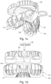
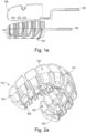
- Figures 1a-1e show an exemplary apparatus 100 comprising a holder 104.
- the holder 104 is configured to receive a mouldable element 106.
- ⁇ mouldable element' as used herein encompasses any material that can be moulded to a user's teeth and/or gums to provide an imprint of those teeth, for example a conformable (e.g. boil and bite) mouth guard or dental putty.
- a conformable e.g. boil and bite
- the holder 104 comprises opposed sidewalls 108 and 110, and a base 112.
- the opposed sidewalls 108, 110 extend from the base 112. Therefore, the base 112 and the opposed sidewalls 108, 110 of the holder 104 form a channel.
- a first sidewall 108 corresponds to the palatal/lingual surface of a user's teeth
- a second sidewall 110 corresponds to the labial/buccal surface of a user's teeth. That is, the opposed sidewalls 108, 110 are configured to be broadly aligned with the palatal/lingual and labial/buccal surfaces of the user's teeth and the base 112 is configured to be broadly aligned with the occlusal plane or biting surface.
- the opposed sidewalls 108, 110 extend along the periphery of the base 112.
- the opposed sidewalls 108, 110 additionally extend upwards from the base 112. They may be at an angle, such that the opposed sidewalls 108, 110 are divergent from the base 112 or could extend generally vertically at 90 degrees to the base 112..
- the opposed sidewalls 108, 110 are configured such that they are movable inwards. That is, the opposed sidewalls 108, 110 are moveable towards each other, such that they are moveable inwards with respect to the channel formed by the opposed sidewalls 108, 110 and the base 112. This movement allows a mouldable element 106 received within the holder 104 to be compressed against the teeth of the user.
- the opposed sidewalls 108, 110 are flexible such that they may be deflected inwards. This is achieved when a user applies a biting force to the mouldable element 106. When the user removes the biting force the opposed sidewalls 108, 110 may be configured to move outwards.
- the initial state of the opposed sidewalls 108, 110 is at a divergent angle from the base 112.
- the opposed sidewalls 108, 110 may be deflected inwards under a force and return to the resting state when the force is removed.
- the opposed sidewalls 108, 110 and the base 112 form a channel within which the mouldable element 106 is received.
- the width of the channel is sufficient to allow reception of the mouldable element 106.
- the width of the channel is further sufficient such that the sidewalls of the mouldable element 106 after use of the apparatus have a width sufficient for the intended purpose of the mouldable element. That is, if the mouldable element is a conformable mouthguard then the width of the walls must be sufficient to provide adequate shock absorption, and if the mouldable element is for casting a model of the user's teeth then the width of walls must be sufficient to provide structural integrity for that purpose.
- the holder 104 forms a compression mechanism configured to move the opposed sidewalls 108, 110 inwards, as described in more detail below.
- the user places the apparatus 100, comprising the holder 104 and the mouldable element 106 into their mouth using a handle 126.
- the mouldable element 106 and holder 104 are compressed between the biting surfaces of the upper and lower teeth of the user. This has the effect of compressing the base 112 of the holder 104.
- the mouldable element 106 may also be manipulated using a handle 128 which is engageable with an aperture 130 defined in the element 106.
- the holder side walls 108,110 are formed with a plurality of hinged fingers 114 which extend from the upper parts of the sidewalls from an area which corresponds to a user's gums when the holder and mouldable element are in place in a user's mouth, down into the lower parts of the holder at least partially across the base 112 of the holder 104.
- the fingers 114 in side profile have a generally L-shaped configuration as shown for example, in Figures 3a-3c .
- one sidewall may be provided with hinged fingers. The description below assumes that both side-walls have hinged fingers 114.
- the fingers 114 are hinged part-way up the side walls so that downward forces 116 in the base region 112 from biting, are translated by rotation of the fingers about the respective hinges 118, into inward compressive forces 120 around the gum area of the user when the holder 104 is in use. Beneath the hinged portion, the fingers 114 are separated from the bulk of the sidewalls 108, 110 with generally vertical slots 121.
- respective pressure pads 122 on the fingers 114 which are formed in the upper area of the fingers, above the hinges 118, correspond with a position at which in use, pressure is applied around a user's gum regions (via a mouldable element 106).
- These pads 122 may be shaped to apply pressure in a desired way.
- These wider pads are supported by strengthening ribs 123 which run generally parallel (vertically in use) with the fingers, either side of the hinges 114.
- each finger has a pair of such ribs 123, near the outer vertical edges of the fingers. This type of strengthening rib can be applied to any of the fingers in either side wall, and depends on the flexibility of the materials used, and the amount of acceptable flex in the fingers, consistent with transmitting biting forces into the users gum area.
- the hinged regions are formed by thin connecting portions which connect the fingers with the bulk of side walls 108, 110.
- These connecting portions 124 elastically deform in use, to allow the fingers a small degree of rotation under biting force and return approximately to their unforced position after the biting force is released to allow separation of the mouldable element from the holder 104.
- These connecting portions may be formed by moulding small notches in the outer face of the holder 104 at the upper ends of the slots 121.
- the apparatus disclosed herein may be configured to provide impressions of the upper and/or lower teeth of the user.
- the holder 104 may be articulated. This allows the holder 104 to shape to an arch of the user's teeth. This will occur automatically when the user places their teeth in a mouldable element 106 received within the holder 104 as the articulated nature of the holder will naturally conform to the user's arch.
- the holder 104 comprises a plurality of articulated sections 104a-c (only three sections are referenced, although the description herein may apply to more than three).
- the exemplary apparatus 100 comprises eleven articulated sections 104a-c, but other numbers of sections are possible.
- the number of articulated sections shown in Figures 1a and 1b is not limiting, and exemplary apparatus may comprise any number of articulated sections.
- Each of the plurality of articulated sections 104a-c are connected by a joint about which adjacent articulated sections 104a-c may be rotated relative to each other.
- the joints may comprise an elongate section of material that is flexible to articulate the sections 104a-c.
- the joint may comprise an elongate plastically or elastically deformable material.
- the joints may together form a spine along the holder base 112.
- the holder 104 is completely manufactured from a plastically and/or elastically deformable material.
- the articulated sections 104a-c are configured such that the holder 104 is able to fit to the unique arch of a user's teeth. In this way the apparatus 100 is suitable for a variety of users.
- the articulated sections 104a-c are configured such that the spacing between each individual articulated section 104a-c at inner and outer peripheries are variable.
- the inner periphery corresponds to the palatal or lingual surface of a user's teeth, while the outer periphery corresponds to the buccal surface of a user's teeth.
- the spacing between each articulated section 104a-c is equal when the holder 104 is in the resting position.
- the distance between each articulated section 104a-c at the inner periphery is equal, and the distance between each articulated section 104a-c at the outer periphery is equal.
- the distance between each articulated section 104a-c may be the same at the inner periphery and at the outer periphery when the holder 104 is in the resting position.
- the separation between the articulated sections 104a-c at the inner and outer peripheries may be configured such that the mouldable element does not escape between the articulated sections 104a-c when the holder opposed sidewalls 108, 110 are moved inwards.
- the separation between the articulated sections 104a-c at the inner and outer peripheries may be configured to allow some bulging of the mouldable element between the articulated sections 104a-c when the holder opposed sidewalls 108, 110 are moved inwards.
- the separation between the articulated sections 104a-c at the inner and outer peripheries may be configured based on the material used for the mouldable element, and in exemplary arrangements may be in a range from 0.5 mm to 2.5 mm, or in a range from 1 mm to 2 mm.
- the articulated sections 104a-c are tapered towards the inner periphery to maintain equal spacing.
- the holder 104 comprises a plurality of articulated sections 104a-c.
- the articulated sections 104a-c of the holder 104 operate in the same way as the articulated sections 104a-c of the holder 104. It can be seen from Figure 1b that each of the plurality of holder articulated sections 104a-c is received by a corresponding articulated section 104a-c of the holder 104. As such, a deflection of each of the plurality of articulated sections 104a-c of the holder 104 results in a deflection of each of the corresponding articulated sections 104a-c of the holder 104.
- each articulated section 104a-c of the holder 104 may deflect about the joint such that the spacing between each articulated section may reduce or increase depending on the arch of the individual user's teeth.
- the articulated sections 104a-c are 'discrete' from each other in that they are separate from each other and are separably operable.
- the term 'discrete' is used in this document to encompass a situation wherein elements have independent operation and/or movement, although they may be joined.
- the articulated sections comprise discrete inner sections and discrete outer sections, and wherein there are fewer discrete inner sections than discrete outer sections to maintain equal spacing.
- the holder opposed sidewalls 108, 110 are the same height, although in other arrangements they may be different heights.
- each holder opposed sidewalls 108, 110 of each articulated section 104a-c are individually moveable inwards. That is, each holder opposed sidewalls 108, 110 of each articulated section 104a-c may be deflected inwards independently. Accordingly, the holder opposed sidewalls 108, 110 of one or more articulated sections 104a-c of the holder 104 may be configured to apply a different inward force to the holder opposed sidewalls 108, 110 of one or more other articulated sections 104a-c. Therefore, the holder opposed sidewalls 108, 110 may be configured to apply a different inward pressure at different locations. For example, this may be done by varying the width of the holder channel, or by varying the height of the holder opposed sidewalls 108, 110.
- the inward compressive forces 120 may be created directly by a user applying a force 130 through their lips, or directly, to the outer faces of the pressure pads 122.
- the pressure pads 122 in the side wall 108 are far more effective at spreading the force evenly, and thereby achieving a better result for the fit of the mouldable element 106, than applying force directly to the mouldable element without the force being transmitted by the pads 122.
- the fingers either do not extend into the base 112 (so are generally linear and not L-shaped) or are arranged to be below the level of the rest of the base 112 so that biting forces are generally not applied to the fingers in use.
- This embodiment may have similar features in other respects, to the other embodiments described above.
Landscapes
- Health & Medical Sciences (AREA)
- Oral & Maxillofacial Surgery (AREA)
- General Health & Medical Sciences (AREA)
- Dentistry (AREA)
- Epidemiology (AREA)
- Life Sciences & Earth Sciences (AREA)
- Animal Behavior & Ethology (AREA)
- Public Health (AREA)
- Veterinary Medicine (AREA)
- Physical Education & Sports Medicine (AREA)
- Dental Tools And Instruments Or Auxiliary Dental Instruments (AREA)
- Body Structure For Vehicles (AREA)
Claims (16)
- Vorrichtung, umfassend:einen Halter (104) zum Aufnehmen eines formbaren Elements (106) und zum Einsetzen in den Mund eines Benutzers, um es dem Benutzer zu ermöglichen, eine Beißkraft auf das formbare Element auszuüben, um einen Abdruck oder eine Anpassung der Zähne des Benutzers bereitzustellen, wobei der Halter eine Halterbasis (112) und gegenüberliegende Halterseitenwände (108, 110) aufweist, die sich von der Halterbasis erstrecken,wobei mindestens eine der gegenüberliegenden Halterseitenwände einen Gelenkfinger (114) beinhaltet, der einen Fingerseitenwandteil, der einen Teil der Halterseitenwand bildet, und einen Fingerbasisteil aufweist, der einen Teil der Halterbasis (112) bildet und an dem Fingerseitenwandteil nach innen bewegt werden kann, wenn das Fingerbasisteil durch eine im Allgemeinen parallel zu den Halterseitenwänden (108, 110) gerichtete Kraft bewegt wird, um im Gebrauch das formbare Element (106) gegen die Zähne des Benutzers zu drücken, und wobei der Finger (114) an einer Position auf halber Höhe seines Seitenwandteils angelenkt ist,so dass nach unten gerichtete Kräfte (116), die vom Beißen in den Fingerbasisteil gerichtet sind, durch die Drehung des Fingers um das Drehgelenk (118) in nach innen gerichtete Druckkräfte (120) am Zahnfleischbereich des Benutzers umgewandelt werden, wenn der Halter im Gebrauch ist.
- Vorrichtung nach einem der vorhergehenden Ansprüche, wobei sich der Finger von den Teilen der Seitenwände (108, 110) aus einem Bereich, der dem Zahnfleisch eines Benutzers entspricht, wenn sich der Halter (104) und das formbare Element (106) im Mund eines Benutzers befinden, bis zu einer Position zumindest teilweise über die Basis (112) des Halters erstreckt.
- Vorrichtung nach einem der vorhergehenden Ansprüche, wobei der Teil des Fingers auf der Basis am nächsten liegenden Seite des Drehgelenks mit Schlitzen vom Hauptteil der Seitenwand getrennt ist.
- Vorrichtung nach einem der vorhergehenden Ansprüche, wobei das Drehgelenk durch dünne Verbindungsabschnitte (124) gebildet ist, die den Finger mit dem Hauptteil der Seitenwand verbinden.
- Vorrichtung nach Anspruch 4, wobei die Verbindungsabschnitte durch Einformen von Kerben in der Außenfläche des Halters an den oberen Enden der Schlitze verdünnt werden.
- Vorrichtung nach einem der vorhergehenden Ansprüche, beinhaltend ein Druckkissen (122) am Finger (114), das an dem von der Halterbasis entfernten Ende des Fingers (114) ausgebildet ist und das einer Position entspricht, an der im Gebrauch über ein formbares Element Druck um die Zahnfleischbereiche eines Benutzers ausgeübt wird.
- Vorrichtung nach einem der vorhergehenden Ansprüche, wobei der Halter gelenkig ist, um den Halter so zu formen, dass er zu einem Zahnbogen des Benutzers passt.
- Vorrichtung nach Anspruch 7, wobei der Halter eine Vielzahl diskreter Gelenkabschnitte (104a-c) umfasst.
- Vorrichtung nach Anspruch 8, wobei die Gelenkabschnitte (104a-c) gleichmäßig beabstandet sind.
- Vorrichtung nach Anspruch 9, wobei die Basis jedes Gelenkabschnitts verjüngt ist, um gleiche Abstände aufrechtzuerhalten.
- Vorrichtung nach einem der Ansprüche 8 bis 10, wobei die Gelenkabschnitte (104a-c) diskrete Innenabschnitte und diskrete Außenabschnitte umfassen und wobei es weniger diskrete Innenabschnitte als diskrete Außenabschnitte gibt, um gleiche Abstände aufrechtzuerhalten.
- Vorrichtung nach einem der vorhergehenden Ansprüche, wobei das formbare Element (106), für dessen Aufnahme der Halter konfiguriert ist, eines von einem Boil-and-Bite-Mundschutz und einem Zahnabdruckmaterial ist.
- Vorrichtung nach einem der vorhergehenden Ansprüche, ferner umfassend das formbare Element (106).
- Teilesatz, umfassend:
ein formbares Element und den Halter nach einem der Ansprüche 1 bis 12. - Vorrichtung, umfassend:einen Halter (104) zum Aufnehmen eines formbaren Elements (106) und zum Einsetzen in den Mund eines Benutzers, um es dem Benutzer zu ermöglichen, eine Kraft auf das formbare Element auszuüben, beispielsweise indem ein Benutzer eine Kraft durch seine Lippen, oder direkt, auf die Außenfläche des Halter ausübt, um einen Abdruck oder eine Anpassung der Zähne des Benutzers bereitzustellen, wobei der Halter eine Halterbasis (112) und gegenüberliegende Halterseitenwände (108, 100) aufweist, die sich von der Halterbasis (112) erstrecken,wobei mindestens eine der gegenüberliegenden Halterseitenwände (108, 110) einen Gelenkfinger (114) mit einem Fingerseitenwandteil aufweist, der einen Teil der Halterseitenwand bildet und der am Fingerseitenwandteil nach innen bewegt werden kann, wenn er durch eine allgemein parallel zur Halterbasis (112) gerichtete Kraft bewegt wird, um im Gebrauch das formbare Element (106) gegen die Zähne des Benutzers zu drücken, und wobei der Finger (114) an einer Position auf halber Höhe seines Seitenwandteils angelenkt ist,so dass in den Finger (114) gerichtete Kräfte durch Drehung des Fingers um das Drehgelenk (118) in nach innen gerichtete Druckkräfte im Zahnfleischbereich des Benutzers umgewandelt und gesteuert werden, wenn der Halter im Gebrauch ist.
- Teilesatz, umfassend:
ein formbares Element (106) und den Halter nach Anspruch 15.
Priority Applications (1)
| Application Number | Priority Date | Filing Date | Title |
|---|---|---|---|
| HRP20231617TT HRP20231617T1 (hr) | 2019-02-08 | 2020-02-10 | Uređaj za namještanje kompresivnog štitnika za usta |
Applications Claiming Priority (2)
| Application Number | Priority Date | Filing Date | Title |
|---|---|---|---|
| GB1901770.6A GB2581194B (en) | 2019-02-08 | 2019-02-08 | Compressive mouthguard fitting device |
| PCT/GB2020/050291 WO2020161503A1 (en) | 2019-02-08 | 2020-02-10 | Compressive mouthguard fitting device |
Publications (2)
| Publication Number | Publication Date |
|---|---|
| EP3897449A1 EP3897449A1 (de) | 2021-10-27 |
| EP3897449B1 true EP3897449B1 (de) | 2023-11-29 |
Family
ID=65996992
Family Applications (1)
| Application Number | Title | Priority Date | Filing Date |
|---|---|---|---|
| EP20705498.2A Active EP3897449B1 (de) | 2019-02-08 | 2020-02-10 | Kompressionspassvorrichtung für mundschutz |
Country Status (10)
| Country | Link |
|---|---|
| US (1) | US12102505B2 (de) |
| EP (1) | EP3897449B1 (de) |
| CN (1) | CN113412097B (de) |
| CA (1) | CA3129256A1 (de) |
| DK (1) | DK3897449T3 (de) |
| ES (1) | ES2967212T3 (de) |
| GB (1) | GB2581194B (de) |
| HR (1) | HRP20231617T1 (de) |
| PL (1) | PL3897449T3 (de) |
| WO (1) | WO2020161503A1 (de) |
Families Citing this family (4)
| Publication number | Priority date | Publication date | Assignee | Title |
|---|---|---|---|---|
| JP1649724S (de) | 2019-01-18 | 2020-01-14 | ||
| GB2581194B (en) | 2019-02-08 | 2021-10-13 | Opro International Ltd | Compressive mouthguard fitting device |
| CA189109S (en) | 2019-02-13 | 2021-12-06 | Opro International Ltd | Tray for mouthguard |
| USD967435S1 (en) * | 2020-11-10 | 2022-10-18 | Solving Digital Dental Inc. | Dental impression tray |
Family Cites Families (44)
| Publication number | Priority date | Publication date | Assignee | Title |
|---|---|---|---|---|
| USRE15265E (en) * | 1922-01-10 | Dental impression- flask or tray | ||
| US1367628A (en) | 1920-05-20 | 1921-02-08 | Finis E Roach | Dental impression flask or tray |
| US1351108A (en) | 1920-06-08 | 1920-08-31 | Thomas F Littlejohn | Dental impression-tray |
| US2549184A (en) | 1948-01-29 | 1951-04-17 | Eliot Van Cortlandt | Dental impression tray |
| FR2336116A1 (fr) | 1975-12-22 | 1977-07-22 | Lion Hamigaki Kk | Dispositif de traitement dentaire par ultrasons |
| US4059101A (en) * | 1976-03-22 | 1977-11-22 | Martin Richmond | Therapeutic device for massaging gingival tissue |
| US4182507A (en) * | 1976-11-29 | 1980-01-08 | Ivan Bekey | Mold for casting articulated castings from registered dental impressions |
| USD281532S (en) | 1983-04-29 | 1985-11-26 | Ipco Corporation | Dental impression tray |
| USD328494S (en) | 1990-10-26 | 1992-08-04 | Schwendeman Allison J | Dental treatment tray |
| US5211559A (en) | 1991-07-18 | 1993-05-18 | Gillette Canada Inc. | Dental treatment tray for holding medicament gel |
| USD403771S (en) | 1997-03-12 | 1999-01-05 | Werrin S Rand | Dental bite tray |
| US6428315B1 (en) * | 2000-06-29 | 2002-08-06 | David Michael Prestipino | Dental impression tray |
| USD473976S1 (en) | 2001-10-25 | 2003-04-29 | Ortho Technology | Mouth guard |
| USD537986S1 (en) | 2002-06-19 | 2007-03-06 | Brain-Pad, Inc. | Mouthguard |
| USD493578S1 (en) | 2002-06-19 | 2004-07-27 | Wipss Products, Inc. | Mouthguard |
| USD509028S1 (en) | 2003-05-16 | 2005-08-30 | Christopher John Farrell | Mouthguard |
| US7361020B2 (en) * | 2003-11-19 | 2008-04-22 | Align Technology, Inc. | Dental tray containing radiopaque materials |
| USD527848S1 (en) | 2004-03-26 | 2006-09-05 | Wipss Products, Inc. | Mouthguard |
| USD525749S1 (en) | 2004-03-26 | 2006-07-25 | Brain-Pad, Inc. | Mouthguard |
| US8376738B2 (en) | 2004-10-20 | 2013-02-19 | Big Jaw Bone, Llc | Universal impression trays and method of use |
| USD554259S1 (en) | 2006-06-14 | 2007-10-30 | Ric Investments, Llc | Oral appliance tray |
| AU319890S (en) | 2007-08-28 | 2008-06-11 | Frame for oral appliance | |
| AU2008221619A1 (en) * | 2007-09-24 | 2009-04-09 | Peter John Herring | Dental Impression Tray |
| CN201101589Y (zh) * | 2007-10-31 | 2008-08-20 | 张国强 | 上下局部义齿同时制模的可调式联体印模托盘 |
| US8998615B2 (en) * | 2009-05-19 | 2015-04-07 | Dentca, Inc. | Method and apparatus for preparing denture |
| US20110171593A1 (en) * | 2010-01-12 | 2011-07-14 | Ross Donald H | Dynamically adjustable dental impression devices and methods for using the same |
| USD663485S1 (en) | 2010-06-02 | 2012-07-10 | Shock Doctor, Inc. | Custom mouthguard |
| CN201798814U (zh) * | 2010-09-28 | 2011-04-20 | 深圳市龙岗中心医院 | 一种口腔种植牙专用印模托盘 |
| USD686733S1 (en) | 2011-12-26 | 2013-07-23 | Gc Corporation | Tray for collecting a dental impression |
| USD686327S1 (en) | 2011-12-26 | 2013-07-16 | Gc Corporation | Tray for collecting a dental impression |
| USD708340S1 (en) | 2012-06-22 | 2014-07-01 | Gc Corporation | Tray for dental impression extraction |
| USD706937S1 (en) | 2012-06-22 | 2014-06-10 | Gc Corporation | Tray for dental impression extraction |
| USD734556S1 (en) | 2013-05-24 | 2015-07-14 | Sportsguard Laboratories, Inc. | Mouthguard with lipguard |
| GB201401548D0 (en) * | 2014-01-30 | 2014-03-19 | Opro Int Ltd | Mouthguard |
| USD743107S1 (en) | 2014-09-11 | 2015-11-10 | Jr286 Technologies, Inc. | Mouthguard |
| GB201602485D0 (en) * | 2016-02-11 | 2016-03-30 | Opro Int Ltd | Impression tray |
| CA3015689C (en) * | 2016-03-11 | 2024-11-12 | National Dentex, Llc | DENTAL IMPRINT HOLDER SYSTEM AND ASSOCIATED METHODS OF USE |
| CN108347771B (zh) | 2017-01-24 | 2019-08-02 | 电信科学技术研究院 | 一种特殊子帧的短tti划分方法及装置 |
| AU201710942S (en) | 2017-02-16 | 2017-10-06 | Orthodontic appliance | |
| USD795501S1 (en) | 2017-04-10 | 2017-08-22 | Jbl Radical Innovations, Llc | Mouthpiece |
| USD862705S1 (en) | 2018-04-30 | 2019-10-08 | Shanghai Mugang Medical Technology Ltd. | Dental appliance |
| USD874654S1 (en) | 2018-07-26 | 2020-02-04 | Dentek Oral Care, Inc. | Dental guard and tray |
| GB2581194B (en) | 2019-02-08 | 2021-10-13 | Opro International Ltd | Compressive mouthguard fitting device |
| USD927696S1 (en) | 2020-11-05 | 2021-08-10 | Evolve Dental Technologies, Inc. | Dental impression tray |
-
2019
- 2019-02-08 GB GB1901770.6A patent/GB2581194B/en active Active
-
2020
- 2020-02-10 ES ES20705498T patent/ES2967212T3/es active Active
- 2020-02-10 HR HRP20231617TT patent/HRP20231617T1/hr unknown
- 2020-02-10 CA CA3129256A patent/CA3129256A1/en active Pending
- 2020-02-10 DK DK20705498.2T patent/DK3897449T3/da active
- 2020-02-10 WO PCT/GB2020/050291 patent/WO2020161503A1/en not_active Ceased
- 2020-02-10 EP EP20705498.2A patent/EP3897449B1/de active Active
- 2020-02-10 CN CN202080012502.XA patent/CN113412097B/zh active Active
- 2020-02-10 US US17/427,713 patent/US12102505B2/en active Active
- 2020-02-10 PL PL20705498.2T patent/PL3897449T3/pl unknown
Also Published As
| Publication number | Publication date |
|---|---|
| EP3897449A1 (de) | 2021-10-27 |
| CN113412097B (zh) | 2023-10-10 |
| HRP20231617T1 (hr) | 2024-05-24 |
| ES2967212T3 (es) | 2024-04-29 |
| GB2581194A (en) | 2020-08-12 |
| CN113412097A (zh) | 2021-09-17 |
| DK3897449T3 (da) | 2024-01-02 |
| GB2581194B (en) | 2021-10-13 |
| GB201901770D0 (en) | 2019-03-27 |
| US20220125560A1 (en) | 2022-04-28 |
| CA3129256A1 (en) | 2020-08-13 |
| WO2020161503A1 (en) | 2020-08-13 |
| PL3897449T3 (pl) | 2024-03-18 |
| US12102505B2 (en) | 2024-10-01 |
Similar Documents
| Publication | Publication Date | Title |
|---|---|---|
| US10610335B2 (en) | Impression tray | |
| US12102505B2 (en) | Power-fit single layer cage | |
| US5293880A (en) | Athletic mouthguard | |
| US4848365A (en) | Method of in-situ custom fitting a protective mouthguard | |
| US4337765A (en) | Mouthguard | |
| EP2331004B1 (de) | Unterteiltes mundstück für die mundpflege | |
| US4063552A (en) | User formed mouthguard | |
| US4668188A (en) | Oral impression tray for forming a mouthguard | |
| US8459267B2 (en) | Mouthguard and method of manufacture therefor | |
| US8297286B2 (en) | Physical rehabilitation and training aid: method of using musculoskeletal repositioning device | |
| US7918228B2 (en) | Musculoskeletal repositioning device | |
| US20110088703A1 (en) | Custom mouthguard | |
| KR101947634B1 (ko) | 높이 조절형 스프린트 및 그것의 제작 방법 | |
| US5244388A (en) | Dental applicator | |
| US8061358B2 (en) | Birthing aid: method of using musculoskeletal repositioning device | |
| US20110174319A1 (en) | Apparatus for the suppression of grinding and/or clenching of teeth | |
| EP3099388B1 (de) | Mundschutz | |
| KR101940741B1 (ko) | 치아교정용 바이트가이드 | |
| KR101883943B1 (ko) | 치아교정용 디지털 브라켓 | |
| KR20180025140A (ko) | 조절 가능한 턱 관절 교합 보조 장치 | |
| KR102597281B1 (ko) | 치열교정용 디지털 브라켓 | |
| KR102619130B1 (ko) | 치열교정용 디지털 브라켓 | |
| US20030056796A1 (en) | Bite guard and method of manufacture |
Legal Events
| Date | Code | Title | Description |
|---|---|---|---|
| REG | Reference to a national code |
Ref country code: HR Ref legal event code: TUEP Ref document number: P20231617T Country of ref document: HR |
|
| STAA | Information on the status of an ep patent application or granted ep patent |
Free format text: STATUS: UNKNOWN |
|
| STAA | Information on the status of an ep patent application or granted ep patent |
Free format text: STATUS: THE INTERNATIONAL PUBLICATION HAS BEEN MADE |
|
| PUAI | Public reference made under article 153(3) epc to a published international application that has entered the european phase |
Free format text: ORIGINAL CODE: 0009012 |
|
| STAA | Information on the status of an ep patent application or granted ep patent |
Free format text: STATUS: REQUEST FOR EXAMINATION WAS MADE |
|
| 17P | Request for examination filed |
Effective date: 20210719 |
|
| AK | Designated contracting states |
Kind code of ref document: A1 Designated state(s): AL AT BE BG CH CY CZ DE DK EE ES FI FR GB GR HR HU IE IS IT LI LT LU LV MC MK MT NL NO PL PT RO RS SE SI SK SM TR |
|
| DAV | Request for validation of the european patent (deleted) | ||
| DAX | Request for extension of the european patent (deleted) | ||
| STAA | Information on the status of an ep patent application or granted ep patent |
Free format text: STATUS: EXAMINATION IS IN PROGRESS |
|
| 17Q | First examination report despatched |
Effective date: 20220831 |
|
| GRAP | Despatch of communication of intention to grant a patent |
Free format text: ORIGINAL CODE: EPIDOSNIGR1 |
|
| STAA | Information on the status of an ep patent application or granted ep patent |
Free format text: STATUS: GRANT OF PATENT IS INTENDED |
|
| INTG | Intention to grant announced |
Effective date: 20230703 |
|
| RIN1 | Information on inventor provided before grant (corrected) |
Inventor name: LOVAT, ANTHONY Inventor name: HONOUR, ANDREW |
|
| GRAS | Grant fee paid |
Free format text: ORIGINAL CODE: EPIDOSNIGR3 |
|
| GRAA | (expected) grant |
Free format text: ORIGINAL CODE: 0009210 |
|
| STAA | Information on the status of an ep patent application or granted ep patent |
Free format text: STATUS: THE PATENT HAS BEEN GRANTED |
|
| P01 | Opt-out of the competence of the unified patent court (upc) registered |
Effective date: 20231017 |
|
| AK | Designated contracting states |
Kind code of ref document: B1 Designated state(s): AL AT BE BG CH CY CZ DE DK EE ES FI FR GB GR HR HU IE IS IT LI LT LU LV MC MK MT NL NO PL PT RO RS SE SI SK SM TR |
|
| REG | Reference to a national code |
Ref country code: GB Ref legal event code: FG4D |
|
| REG | Reference to a national code |
Ref country code: CH Ref legal event code: EP |
|
| REG | Reference to a national code |
Ref country code: DE Ref legal event code: R096 Ref document number: 602020021850 Country of ref document: DE |
|
| REG | Reference to a national code |
Ref country code: IE Ref legal event code: FG4D |
|
| REG | Reference to a national code |
Ref country code: NO Ref legal event code: T2 Effective date: 20231129 |
|
| REG | Reference to a national code |
Ref country code: SE Ref legal event code: TRGR Ref country code: DK Ref legal event code: T3 Effective date: 20231215 |
|
| REG | Reference to a national code |
Ref country code: NL Ref legal event code: FP |
|
| REG | Reference to a national code |
Ref country code: SK Ref legal event code: T3 Ref document number: E 43127 Country of ref document: SK |
|
| REG | Reference to a national code |
Ref country code: HR Ref legal event code: ODRP Ref document number: P20231617T Country of ref document: HR Payment date: 20240201 Year of fee payment: 5 |
|
| REG | Reference to a national code |
Ref country code: LT Ref legal event code: MG9D |
|
| PG25 | Lapsed in a contracting state [announced via postgrant information from national office to epo] |
Ref country code: GR Free format text: LAPSE BECAUSE OF FAILURE TO SUBMIT A TRANSLATION OF THE DESCRIPTION OR TO PAY THE FEE WITHIN THE PRESCRIBED TIME-LIMIT Effective date: 20240301 |
|
| PG25 | Lapsed in a contracting state [announced via postgrant information from national office to epo] |
Ref country code: IS Free format text: LAPSE BECAUSE OF FAILURE TO SUBMIT A TRANSLATION OF THE DESCRIPTION OR TO PAY THE FEE WITHIN THE PRESCRIBED TIME-LIMIT Effective date: 20240329 |
|
| PG25 | Lapsed in a contracting state [announced via postgrant information from national office to epo] |
Ref country code: LT Free format text: LAPSE BECAUSE OF FAILURE TO SUBMIT A TRANSLATION OF THE DESCRIPTION OR TO PAY THE FEE WITHIN THE PRESCRIBED TIME-LIMIT Effective date: 20231129 |
|
| REG | Reference to a national code |
Ref country code: ES Ref legal event code: FG2A Ref document number: 2967212 Country of ref document: ES Kind code of ref document: T3 Effective date: 20240429 |
|
| PG25 | Lapsed in a contracting state [announced via postgrant information from national office to epo] |
Ref country code: LT Free format text: LAPSE BECAUSE OF FAILURE TO SUBMIT A TRANSLATION OF THE DESCRIPTION OR TO PAY THE FEE WITHIN THE PRESCRIBED TIME-LIMIT Effective date: 20231129 Ref country code: IS Free format text: LAPSE BECAUSE OF FAILURE TO SUBMIT A TRANSLATION OF THE DESCRIPTION OR TO PAY THE FEE WITHIN THE PRESCRIBED TIME-LIMIT Effective date: 20240329 Ref country code: GR Free format text: LAPSE BECAUSE OF FAILURE TO SUBMIT A TRANSLATION OF THE DESCRIPTION OR TO PAY THE FEE WITHIN THE PRESCRIBED TIME-LIMIT Effective date: 20240301 Ref country code: BG Free format text: LAPSE BECAUSE OF FAILURE TO SUBMIT A TRANSLATION OF THE DESCRIPTION OR TO PAY THE FEE WITHIN THE PRESCRIBED TIME-LIMIT Effective date: 20240229 |
|
| REG | Reference to a national code |
Ref country code: AT Ref legal event code: MK05 Ref document number: 1635316 Country of ref document: AT Kind code of ref document: T Effective date: 20231129 |
|
| REG | Reference to a national code |
Ref country code: HR Ref legal event code: T1PR Ref document number: P20231617 Country of ref document: HR |
|
| PG25 | Lapsed in a contracting state [announced via postgrant information from national office to epo] |
Ref country code: RS Free format text: LAPSE BECAUSE OF FAILURE TO SUBMIT A TRANSLATION OF THE DESCRIPTION OR TO PAY THE FEE WITHIN THE PRESCRIBED TIME-LIMIT Effective date: 20231129 Ref country code: LV Free format text: LAPSE BECAUSE OF FAILURE TO SUBMIT A TRANSLATION OF THE DESCRIPTION OR TO PAY THE FEE WITHIN THE PRESCRIBED TIME-LIMIT Effective date: 20231129 |
|
| PG25 | Lapsed in a contracting state [announced via postgrant information from national office to epo] |
Ref country code: AT Free format text: LAPSE BECAUSE OF FAILURE TO SUBMIT A TRANSLATION OF THE DESCRIPTION OR TO PAY THE FEE WITHIN THE PRESCRIBED TIME-LIMIT Effective date: 20231129 |
|
| PG25 | Lapsed in a contracting state [announced via postgrant information from national office to epo] |
Ref country code: SM Free format text: LAPSE BECAUSE OF FAILURE TO SUBMIT A TRANSLATION OF THE DESCRIPTION OR TO PAY THE FEE WITHIN THE PRESCRIBED TIME-LIMIT Effective date: 20231129 Ref country code: RO Free format text: LAPSE BECAUSE OF FAILURE TO SUBMIT A TRANSLATION OF THE DESCRIPTION OR TO PAY THE FEE WITHIN THE PRESCRIBED TIME-LIMIT Effective date: 20231129 Ref country code: EE Free format text: LAPSE BECAUSE OF FAILURE TO SUBMIT A TRANSLATION OF THE DESCRIPTION OR TO PAY THE FEE WITHIN THE PRESCRIBED TIME-LIMIT Effective date: 20231129 Ref country code: AT Free format text: LAPSE BECAUSE OF FAILURE TO SUBMIT A TRANSLATION OF THE DESCRIPTION OR TO PAY THE FEE WITHIN THE PRESCRIBED TIME-LIMIT Effective date: 20231129 |
|
| PG25 | Lapsed in a contracting state [announced via postgrant information from national office to epo] |
Ref country code: PT Free format text: LAPSE BECAUSE OF FAILURE TO SUBMIT A TRANSLATION OF THE DESCRIPTION OR TO PAY THE FEE WITHIN THE PRESCRIBED TIME-LIMIT Effective date: 20240401 |
|
| PG25 | Lapsed in a contracting state [announced via postgrant information from national office to epo] |
Ref country code: PT Free format text: LAPSE BECAUSE OF FAILURE TO SUBMIT A TRANSLATION OF THE DESCRIPTION OR TO PAY THE FEE WITHIN THE PRESCRIBED TIME-LIMIT Effective date: 20240401 |
|
| REG | Reference to a national code |
Ref country code: DE Ref legal event code: R097 Ref document number: 602020021850 Country of ref document: DE |
|
| PG25 | Lapsed in a contracting state [announced via postgrant information from national office to epo] |
Ref country code: MC Free format text: LAPSE BECAUSE OF FAILURE TO SUBMIT A TRANSLATION OF THE DESCRIPTION OR TO PAY THE FEE WITHIN THE PRESCRIBED TIME-LIMIT Effective date: 20231129 |
|
| PLBE | No opposition filed within time limit |
Free format text: ORIGINAL CODE: 0009261 |
|
| STAA | Information on the status of an ep patent application or granted ep patent |
Free format text: STATUS: NO OPPOSITION FILED WITHIN TIME LIMIT |
|
| PG25 | Lapsed in a contracting state [announced via postgrant information from national office to epo] |
Ref country code: LU Free format text: LAPSE BECAUSE OF NON-PAYMENT OF DUE FEES Effective date: 20240210 |
|
| PG25 | Lapsed in a contracting state [announced via postgrant information from national office to epo] |
Ref country code: SI Free format text: LAPSE BECAUSE OF FAILURE TO SUBMIT A TRANSLATION OF THE DESCRIPTION OR TO PAY THE FEE WITHIN THE PRESCRIBED TIME-LIMIT Effective date: 20231129 |
|
| PG25 | Lapsed in a contracting state [announced via postgrant information from national office to epo] |
Ref country code: SI Free format text: LAPSE BECAUSE OF FAILURE TO SUBMIT A TRANSLATION OF THE DESCRIPTION OR TO PAY THE FEE WITHIN THE PRESCRIBED TIME-LIMIT Effective date: 20231129 Ref country code: LU Free format text: LAPSE BECAUSE OF NON-PAYMENT OF DUE FEES Effective date: 20240210 |
|
| 26N | No opposition filed |
Effective date: 20240830 |
|
| REG | Reference to a national code |
Ref country code: HR Ref legal event code: ODRP Ref document number: P20231617 Country of ref document: HR Payment date: 20250130 Year of fee payment: 6 |
|
| PGFP | Annual fee paid to national office [announced via postgrant information from national office to epo] |
Ref country code: ES Payment date: 20250331 Year of fee payment: 6 |
|
| PG25 | Lapsed in a contracting state [announced via postgrant information from national office to epo] |
Ref country code: CY Free format text: LAPSE BECAUSE OF FAILURE TO SUBMIT A TRANSLATION OF THE DESCRIPTION OR TO PAY THE FEE WITHIN THE PRESCRIBED TIME-LIMIT; INVALID AB INITIO Effective date: 20200210 |
|
| PG25 | Lapsed in a contracting state [announced via postgrant information from national office to epo] |
Ref country code: HU Free format text: LAPSE BECAUSE OF FAILURE TO SUBMIT A TRANSLATION OF THE DESCRIPTION OR TO PAY THE FEE WITHIN THE PRESCRIBED TIME-LIMIT; INVALID AB INITIO Effective date: 20200210 |
|
| PG25 | Lapsed in a contracting state [announced via postgrant information from national office to epo] |
Ref country code: FI Free format text: LAPSE BECAUSE OF FAILURE TO SUBMIT A TRANSLATION OF THE DESCRIPTION OR TO PAY THE FEE WITHIN THE PRESCRIBED TIME-LIMIT Effective date: 20231129 |
|
| PG25 | Lapsed in a contracting state [announced via postgrant information from national office to epo] |
Ref country code: TR Free format text: LAPSE BECAUSE OF FAILURE TO SUBMIT A TRANSLATION OF THE DESCRIPTION OR TO PAY THE FEE WITHIN THE PRESCRIBED TIME-LIMIT Effective date: 20231129 |
|
| REG | Reference to a national code |
Ref country code: HR Ref legal event code: ODRP Ref document number: P20231617 Country of ref document: HR Payment date: 20260129 Year of fee payment: 7 |
|
| REG | Reference to a national code |
Ref country code: CH Ref legal event code: U11 Free format text: ST27 STATUS EVENT CODE: U-0-0-U10-U11 (AS PROVIDED BY THE NATIONAL OFFICE) Effective date: 20260301 |
|
| PGFP | Annual fee paid to national office [announced via postgrant information from national office to epo] |
Ref country code: NL Payment date: 20260218 Year of fee payment: 7 |
|
| PGFP | Annual fee paid to national office [announced via postgrant information from national office to epo] |
Ref country code: SE Payment date: 20260218 Year of fee payment: 7 |
|
| PGFP | Annual fee paid to national office [announced via postgrant information from national office to epo] |
Ref country code: GB Payment date: 20260220 Year of fee payment: 7 |
|
| PGFP | Annual fee paid to national office [announced via postgrant information from national office to epo] |
Ref country code: NO Payment date: 20260220 Year of fee payment: 7 Ref country code: DE Payment date: 20260218 Year of fee payment: 7 Ref country code: DK Payment date: 20260220 Year of fee payment: 7 Ref country code: IE Payment date: 20260218 Year of fee payment: 7 |
|
| PGFP | Annual fee paid to national office [announced via postgrant information from national office to epo] |
Ref country code: HR Payment date: 20260129 Year of fee payment: 7 |
|
| PGFP | Annual fee paid to national office [announced via postgrant information from national office to epo] |
Ref country code: BE Payment date: 20260218 Year of fee payment: 7 Ref country code: IT Payment date: 20260219 Year of fee payment: 7 |
|
| PGFP | Annual fee paid to national office [announced via postgrant information from national office to epo] |
Ref country code: FR Payment date: 20260219 Year of fee payment: 7 |
|
| PGFP | Annual fee paid to national office [announced via postgrant information from national office to epo] |
Ref country code: CH Payment date: 20260301 Year of fee payment: 7 Ref country code: CZ Payment date: 20260204 Year of fee payment: 7 |
|
| PGFP | Annual fee paid to national office [announced via postgrant information from national office to epo] |
Ref country code: PL Payment date: 20260129 Year of fee payment: 7 |
|
| PGFP | Annual fee paid to national office [announced via postgrant information from national office to epo] |
Ref country code: SK Payment date: 20260204 Year of fee payment: 7 |