EP3897293B1 - Sliding drawer with anti-lifting system - Google Patents
Sliding drawer with anti-lifting system Download PDFInfo
- Publication number
- EP3897293B1 EP3897293B1 EP19836528.0A EP19836528A EP3897293B1 EP 3897293 B1 EP3897293 B1 EP 3897293B1 EP 19836528 A EP19836528 A EP 19836528A EP 3897293 B1 EP3897293 B1 EP 3897293B1
- Authority
- EP
- European Patent Office
- Prior art keywords
- arm
- shelf
- drawer
- front segment
- cavity
- Prior art date
- Legal status (The legal status is an assumption and is not a legal conclusion. Google has not performed a legal analysis and makes no representation as to the accuracy of the status listed.)
- Active
Links
Images

Classifications
-
- A—HUMAN NECESSITIES
- A47—FURNITURE; DOMESTIC ARTICLES OR APPLIANCES; COFFEE MILLS; SPICE MILLS; SUCTION CLEANERS IN GENERAL
- A47B—TABLES; DESKS; OFFICE FURNITURE; CABINETS; DRAWERS; GENERAL DETAILS OF FURNITURE
- A47B88/00—Drawers for tables, cabinets or like furniture; Guides for drawers
- A47B88/40—Sliding drawers; Slides or guides therefor
- A47B88/407—Adjustably or detachably mounted drawers
-
- A—HUMAN NECESSITIES
- A47—FURNITURE; DOMESTIC ARTICLES OR APPLIANCES; COFFEE MILLS; SPICE MILLS; SUCTION CLEANERS IN GENERAL
- A47B—TABLES; DESKS; OFFICE FURNITURE; CABINETS; DRAWERS; GENERAL DETAILS OF FURNITURE
- A47B88/00—Drawers for tables, cabinets or like furniture; Guides for drawers
- A47B88/40—Sliding drawers; Slides or guides therefor
- A47B88/423—Fastening devices for slides or guides
- A47B88/427—Fastening devices for slides or guides at drawer side
-
- A—HUMAN NECESSITIES
- A47—FURNITURE; DOMESTIC ARTICLES OR APPLIANCES; COFFEE MILLS; SPICE MILLS; SUCTION CLEANERS IN GENERAL
- A47B—TABLES; DESKS; OFFICE FURNITURE; CABINETS; DRAWERS; GENERAL DETAILS OF FURNITURE
- A47B88/00—Drawers for tables, cabinets or like furniture; Guides for drawers
- A47B88/40—Sliding drawers; Slides or guides therefor
- A47B88/423—Fastening devices for slides or guides
- A47B88/427—Fastening devices for slides or guides at drawer side
- A47B2088/4276—Fastening devices for slides or guides at drawer side at drawer front via latch means or locking lever
-
- A—HUMAN NECESSITIES
- A47—FURNITURE; DOMESTIC ARTICLES OR APPLIANCES; COFFEE MILLS; SPICE MILLS; SUCTION CLEANERS IN GENERAL
- A47B—TABLES; DESKS; OFFICE FURNITURE; CABINETS; DRAWERS; GENERAL DETAILS OF FURNITURE
- A47B2210/00—General construction of drawers, guides and guide devices
- A47B2210/0002—Guide construction for drawers
- A47B2210/0051—Guide position
- A47B2210/0054—Adjustment of position of slides
-
- A—HUMAN NECESSITIES
- A47—FURNITURE; DOMESTIC ARTICLES OR APPLIANCES; COFFEE MILLS; SPICE MILLS; SUCTION CLEANERS IN GENERAL
- A47B—TABLES; DESKS; OFFICE FURNITURE; CABINETS; DRAWERS; GENERAL DETAILS OF FURNITURE
- A47B2210/00—General construction of drawers, guides and guide devices
- A47B2210/0002—Guide construction for drawers
- A47B2210/0051—Guide position
- A47B2210/0056—Guide located at the bottom of the drawer
Definitions
- the invention relates to an anti-release system for sliding drawers or shelves, or an anti-lifting system for sliding drawers or shelves.
- the invention refers to an improved telescopic guide for drawers or shelves, of the type comprising a device for adjusting the position of the drawer with respect to both its seat and the others drawers or shelves.
- drawers or shelves which in some models are horizontally sliding and removable.
- the drawer or shelf can have integral guides, e.g. the classic grooves on the sides, or is mounted on two linear guides fixed to the walls of the furniture.
- the guides are often sophisticated devices, which allow a fine adjustment of the position of the drawer, see e.g. EP1621107 .
- the drawer can be moved laterally so as to allow adjustment of its horizontal level and the correct spacing from the other drawers and from the sides of the cabinet.
- the drawer or shelf is constrained to the guides to prevent its disengagement in the vertical direction or its accidental detachment.
- the known constraint means are generally complicated to produce and difficult to use during the installation phase.
- GB 2 449 894 A and US 2003 /234603 A disclose mounting assemblies for sliding drawers.
- Another object is to provide a guide of the above mentioned type in which the means of vertical constraint for the drawer or shelf are simple to produce and easy to use during assembly.
- Another object is to provide a guide of the above mentioned type wherein the size of the constraint means is limited.
- Another object is to provide a guide of the above mentioned type which integrates vertical restraint means against the vertical disengagement of the drawer or shelf from the guides.
- Another object is to provide an improved assembly given by a guide of the above mentioned type and an associated drawer or shelf.
- Another object is to provide an improved sliding drawer or shelf associated with a guide of the type mentioned above.
- a sliding drawer or shelf of a piece of furniture according to claim 1 is proposed to this purpose.
- the stop element comprises or forms a cavity in which a free end of the arm can be trapped, so that the free end of the arm opposes a lifting of the perimeter frame by abutting against a wall of the cavity.
- the cavity is advantageously producible in a simple and inexpensive way, and may be e.g. a hole, a recess, or an undercut of the front segment.
- the drawer or shelf comprises a component mounted superficially on the front segment to form the cavity.
- the cavity is created by the same component mounted superficially or by cooperation of the component mounted superficially and parts of the front segment.
- said component comprises a step and is mounted on the front segment so that the cavity is made from a surface of the step and a wall of the front segment.
- said component is a solid with L-shaped cross section, to determine said step.
- the free end of the arm comprises a protruding tooth adapted for being inserted into the cavity.
- the protruding tooth is arranged along a longitudinal axis of the arm.
- the adjustment element comprises an element mounted movably or rotatably on the arm to protrude from the arm and abutting against the perimeter frame by means of an adjustable-protrusion portion.
- the element is rotatably mounted, it is preferred that it is provided with a thread and is screwed into the arm to protrude from the arm via an adjustable-protrusion portion. Screwing is a simple and precise form of adjustment.
- the front segment and the three C-connected segments are hollow tubular elements, each with ends cut at 45 degrees for fitting with the ends of two other segments.
- other structures are possible.
- the three C-connected segments are e.g. hollow tubular elements, each with ends cut at 45 degrees to fit ends of the other two segments, and the front segment comprises a rigid wall provided with two anchoring members that protrude orthogonally therefrom and are each insertable in a respective cavity of a different segment forming the C.
- Fig. 1 partially shows the side walls 10 of a piece of furniture or cabinet inside which there is mounted a sliding drawer or shelf 12.
- the sliding drawer or shelf 12 comprises a frame having a front segment 14, a bottom segment 16 and two lateral segments 18.
- the segments 14, 16, 18 are tubular parts with ends cut at 45 degrees to fit to each other, and are assembled to form an overall rectangular or square frame. For simplicity, the bottom of the sliding drawer or shelf 12 is not shown.
- the lateral segments 18 are respectively mounted above two linear guides 20 which are specularly identical and fixed to the walls 10.
- Each linear telescopic guide 20 comprises two parts 22, 24 which are linearly translatable relatively to each other.
- the part 22 is fixed and connectable/connected to the wall 10, while the part 24, translatable along a X axis with respect to part 22, can be connected to one of the segments 18.
- the sliding drawer or shelf 12 can be removed frontally from the furniture item.
- the translatable part 24 comprises a horizontal arm 26 on which the sliding drawer or shelf 12 is placed.
- the guide 20 comprises an adjustment device for the inclination of the drawer or shelf 12 with respect to the fixed part 24.
- this inclination adjustment device e.g. the end of the arm 26 closest to the front segment 14 is equipped with a screw 80, screwable vertically into the arm 26 so that the tip of the screw 80 protrudes from the arm 26 under the drawer or shelf 12.
- the tip of the screw 80 can protrude more or less from the arm 26 and lift more or less the drawer or shelf 12 (or a segment 18). This allows an adjustment of the inclination of the drawer or shelf 12.
- the guide 20 comprises a rear stop element (not shown) to avoid detachment of the drawer or shelf 12.
- a block 50 Inside the front segment 14, on the surface facing the inside of the sliding drawer or shelf 12, there is integrally mounted, e.g. with screws or adhesive, a block 50 (see also fig. 6 and 7 ).
- the block 50 is a parallelepiped lacking an edge, so it is made as a sort of three-dimensional L.
- the block 50 comprises a step 52 defined by the union of two parallelepipeds 56, 54 having different bases and two coplanar sides.
- the block 50 is mounted on the segment 14 so that the step forms a cavity 60 in the internal wall of the segment 14.
- the horizontal arm 26 is preferably movable back and forth with respect to part 24 through an initial adjustment, during assembly, while during ordinary use the horizontal arm 26 remains integral with the part 24.
- the adjustment of the horizontal arm 26 can be used, during assembly, to tune-up the horizontal position of the drawer or shelf 12 with respect to the walls 10.
- the horizontal arm 26 is fixed on - and integral with - the part 24.
- the tooth 28 is inserted into the cavity 60 (see fig. 4 ). In this way, during ordinary use, the tooth 28 opposes to a lifting of the parallelepiped 54 when the sliding drawer or shelf 12 (see arrow F) is pushed up. In other words, if one tries to lift the sliding drawer or shelf 12 (see arrow F) the parallelepiped 54 hits the tooth 28 and the sliding drawer or shelf 12 remains locked into horizontal position and does not detach itself from the guide 20.
- the tooth 28 may be positioned in the cavity 60 either by translating the arm 26 towards the sliding drawer or shelf 12, if the arm is adjustable, or by eventually fixing the block 50 to the front segment, so as to build the cavity 60 around the tooth 28.
- Fig. 5 shows a solution similar to fig. 4 but applied to a sliding drawer or shelf 70 of different type.
- the sliding drawer or shelf 70 comprises a C-shaped frame, made from tubular elements.
- the C-shaped frame has a bottom segment (no shown) joined to two lateral segments 72.
- the front segment 74 is mounted on the C to form an overall rectangular or square frame. The assembly takes place by equipping the front segment 74 with two lateral anchoring members 76, inserted by interlocking inside hollow ends of the lateral segments 72.
- the element 50 is mounted on the internal wall of the front segment 74, e.g. in correspondence of one of the two anchoring members 76.
- the setting of the element 50 is a fast and inexpensive solution to constrain the guide 20 to a sliding drawer or shelf. Because the element 50 is removable or applicable independently of the rest, another advantage is being able to retrofit with an anti-lifting system a pre-existing drawer or shelf, by adding the element 50. Or one can quickly release the drawer or shelf from the guide 20 only by removing the element 50, without acting on the horizontal adjustment of the arm 26.
- the element opposing the lifting of the drawer or shelf can also be built in different ways, e.g.
Landscapes
- Drawers Of Furniture (AREA)
- Transplanting Machines (AREA)
Description
- The invention relates to an anti-release system for sliding drawers or shelves, or an anti-lifting system for sliding drawers or shelves. In particular, the invention refers to an improved telescopic guide for drawers or shelves, of the type comprising a device for adjusting the position of the drawer with respect to both its seat and the others drawers or shelves.
- It is known that furniture or cabinets are furnished with drawers or shelves, which in some models are horizontally sliding and removable. The drawer or shelf can have integral guides, e.g. the classic grooves on the sides, or is mounted on two linear guides fixed to the walls of the furniture.
- The guides are often sophisticated devices, which allow a fine adjustment of the position of the drawer, see e.g.
EP1621107 . Thus the drawer can be moved laterally so as to allow adjustment of its horizontal level and the correct spacing from the other drawers and from the sides of the cabinet. - The drawer or shelf is constrained to the guides to prevent its disengagement in the vertical direction or its accidental detachment. Unfortunately the known constraint means are generally complicated to produce and difficult to use during the installation phase.
-
GB 2 449 894 A US 2003 /234603 A disclose mounting assemblies for sliding drawers. - Improving this state of the art is the main object of the invention, which is defined in the appended claims, wherein the dependent ones define advantageous variants.
- Another object is to provide a guide of the above mentioned type in which the means of vertical constraint for the drawer or shelf are simple to produce and easy to use during assembly.
- Another object is to provide a guide of the above mentioned type wherein the size of the constraint means is limited.
- Another object is to provide a guide of the above mentioned type which integrates vertical restraint means against the vertical disengagement of the drawer or shelf from the guides.
- Another object is to provide an improved assembly given by a guide of the above mentioned type and an associated drawer or shelf.
- Another object is to provide an improved sliding drawer or shelf associated with a guide of the type mentioned above.
- A sliding drawer or shelf of a piece of furniture according to claim 1 is proposed to this purpose.
- This solution prevents the perimeter frame from accidentally lifting.
- The stop element comprises or forms a cavity in which a free end of the arm can be trapped, so that the free end of the arm opposes a lifting of the perimeter frame by abutting against a wall of the cavity.
- The cavity is advantageously producible in a simple and inexpensive way, and may be e.g. a hole, a recess, or an undercut of the front segment.
- It is desired not to affect the surface of the front segment, so the drawer or shelf comprises a component mounted superficially on the front segment to form the cavity. The cavity is created by the same component mounted superficially or by cooperation of the component mounted superficially and parts of the front segment.
- According to a preferred embodiment, said component comprises a step and is mounted on the front segment so that the cavity is made from a surface of the step and a wall of the front segment.
- Preferably, said component is a solid with L-shaped cross section, to determine said step.
- The free end of the arm comprises a protruding tooth adapted for being inserted into the cavity. To minimize the overall dimensions, the protruding tooth is arranged along a longitudinal axis of the arm.
- Preferably the adjustment element comprises an element mounted movably or rotatably on the arm to protrude from the arm and abutting against the perimeter frame by means of an adjustable-protrusion portion. In particular, if the element is rotatably mounted, it is preferred that it is provided with a thread and is screwed into the arm to protrude from the arm via an adjustable-protrusion portion. Screwing is a simple and precise form of adjustment.
- Preferably the front segment and the three C-connected segments are hollow tubular elements, each with ends cut at 45 degrees for fitting with the ends of two other segments. However, other structures are possible.
- In particular, the three C-connected segments are e.g. hollow tubular elements, each with ends cut at 45 degrees to fit ends of the other two segments, and the front segment comprises a rigid wall provided with two anchoring members that protrude orthogonally therefrom and are each insertable in a respective cavity of a different segment forming the C.
- The advantages of the invention will be even clearer from the following description of a preferred exemplary system, referring to the attached drawing in which
-
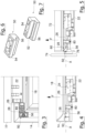
Fig. 1 shows a three-dimensional view of a sliding drawer inserted in a piece of furniture; -
Fig. 2 shows a three-dimensional view from below of a drawer; -
Fig. 3 shows a plan view of the elements offig. 2 ; -
Fig. 4 shows a cross-sectional view according to a vertical plane passing through the X axis offig. 1 ; -
Fig. 5 shows a variant of the system; -
Fig. 6 shows a three-dimensional view of a component of the system; -
Fig. 7 shows a different three-dimensional view of the component ofFig. 6 . - In the figures equal numbers indicate equal or conceptually similar parts, and the elements are described as in use. In order not to crowd the figures some numerical references are omitted.
-
Fig. 1 partially shows theside walls 10 of a piece of furniture or cabinet inside which there is mounted a sliding drawer orshelf 12. - The sliding drawer or
shelf 12 comprises a frame having afront segment 14, abottom segment 16 and twolateral segments 18. Thesegments shelf 12 is not shown. - The
lateral segments 18 are respectively mounted above twolinear guides 20 which are specularly identical and fixed to thewalls 10. - Each linear
telescopic guide 20 comprises twoparts part 22 is fixed and connectable/connected to thewall 10, while thepart 24, translatable along a X axis with respect topart 22, can be connected to one of thesegments 18. Thus the sliding drawer orshelf 12 can be removed frontally from the furniture item. - With reference to
figures. 2-4 , one can see the sliding drawer orshelf 12 mounted on theguide 20. Thetranslatable part 24 comprises ahorizontal arm 26 on which the sliding drawer orshelf 12 is placed. Thearm 26, at the end closest to thefront segment 14, ends with aprotruding tooth 28, which extends cantilevered from thearm 26 lying on a - in use - horizontal plane. - The
guide 20 comprises an adjustment device for the inclination of the drawer orshelf 12 with respect to thefixed part 24. To make this inclination adjustment device e.g. the end of thearm 26 closest to thefront segment 14 is equipped with ascrew 80, screwable vertically into thearm 26 so that the tip of thescrew 80 protrudes from thearm 26 under the drawer orshelf 12. By screwing more or less thescrew 80, the tip of thescrew 80 can protrude more or less from thearm 26 and lift more or less the drawer or shelf 12 (or a segment 18). This allows an adjustment of the inclination of the drawer orshelf 12. - Preferably the
guide 20 comprises a rear stop element (not shown) to avoid detachment of the drawer orshelf 12. - Inside the
front segment 14, on the surface facing the inside of the sliding drawer orshelf 12, there is integrally mounted, e.g. with screws or adhesive, a block 50 (see alsofig. 6 and 7 ). Theblock 50 is a parallelepiped lacking an edge, so it is made as a sort of three-dimensional L. In other words, theblock 50 comprises astep 52 defined by the union of twoparallelepipeds block 50 is mounted on thesegment 14 so that the step forms acavity 60 in the internal wall of thesegment 14. - The
horizontal arm 26 is preferably movable back and forth with respect topart 24 through an initial adjustment, during assembly, while during ordinary use thehorizontal arm 26 remains integral with thepart 24. In particular the adjustment of thehorizontal arm 26 can be used, during assembly, to tune-up the horizontal position of the drawer orshelf 12 with respect to thewalls 10. - Or the
horizontal arm 26 is fixed on - and integral with - thepart 24. - At the end of the assembly of the sliding drawer or
shelf 12 on the guides 30 20, thetooth 28 is inserted into the cavity 60 (seefig. 4 ). In this way, during ordinary use, thetooth 28 opposes to a lifting of theparallelepiped 54 when the sliding drawer or shelf 12 (see arrow F) is pushed up. In other words, if one tries to lift the sliding drawer or shelf 12 (see arrow F) theparallelepiped 54 hits thetooth 28 and the sliding drawer orshelf 12 remains locked into horizontal position and does not detach itself from theguide 20. - The
tooth 28 may be positioned in thecavity 60 either by translating thearm 26 towards the sliding drawer orshelf 12, if the arm is adjustable, or by eventually fixing theblock 50 to the front segment, so as to build thecavity 60 around thetooth 28. -
Fig. 5 shows a solution similar tofig. 4 but applied to a sliding drawer or shelf 70 of different type. - The sliding drawer or shelf 70 comprises a C-shaped frame, made from tubular elements. The C-shaped frame has a bottom segment (no shown) joined to two
lateral segments 72. Thefront segment 74 is mounted on the C to form an overall rectangular or square frame. The assembly takes place by equipping thefront segment 74 with twolateral anchoring members 76, inserted by interlocking inside hollow ends of thelateral segments 72. - With the same function previously described, the
element 50 is mounted on the internal wall of thefront segment 74, e.g. in correspondence of one of the two anchoringmembers 76. - The setting of the
element 50 is a fast and inexpensive solution to constrain theguide 20 to a sliding drawer or shelf. Because theelement 50 is removable or applicable independently of the rest, another advantage is being able to retrofit with an anti-lifting system a pre-existing drawer or shelf, by adding theelement 50. Or one can quickly release the drawer or shelf from theguide 20 only by removing theelement 50, without acting on the horizontal adjustment of thearm 26. - The element opposing the lifting of the drawer or shelf can also be built in different ways, e.g.
- a block having an inclined plane (see
fig. 7 ) or a concavity with which to obstruct thetooth 28; and/or - a block having a hole or a groove in which to insert the
tooth 28; and/or - a ring in which to insert the
tooth 28; and/or - an arch mounted cantilevered on the internal wall of the drawer or shelf.
Claims (6)
- Sliding drawer or shelf (12) of a piece of furniture, comprising:a perimeter frame defined by the union of a front segment (14) and three C-connected segments (16, 18), the front segment (14) comprising a stop element (50) comprising or forming a cavity;a telescopic guide (20) for linearly moving the drawer or shelf with respect to the piece of furniture, the guide comprisinga fixed part (22) that can be fixed on the piece of furniture, anda translatable part (24) longitudinally translatable with respect to the fixed part, the translatable part comprising an arm (26) which is adapted to support the perimeter frame and on which there is mounted an adjustment element (80) for the inclination of the perimeter frame with respect to the fixed part,the free end of the arm (26) comprising a protruding tooth (28) adapted to be inserted into and trapped by the cavity and arranged along a longitudinal axis (X) of the arm,so that the protruding tooth (28) opposes to a lifting of the perimeter frame by abutting against a wall of the cavity,wherein the stop element (50) is a component (50) superficially mounted on the front segment to form the cavity,the cavity being created by said component (50) or by the cooperation of said component (50) and parts of the front segment (14).
- Sliding drawer or shelf according to claim 1, wherein the component (50) comprises a step (52) and is mounted on the front segment (14) so that the cavity is formed by a surface of the step (52) and a wall of the front segment (14).
- Sliding drawer or shelf according to claim 1 or 2, wherein the component (50) is a solid with an L-shaped cross-section.
- Sliding drawer or shelf according to any one of the previous claims, wherein the adjustment element comprises an element (80) rotatably mounted in the arm to protrude from the arm and to abut on the drawer or shelf by means of an adjustable-projection portion.
- Sliding drawer or shelf according to claim 4, wherein the rotatably mounted element (80) is provided with a thread and is screwed into the arm to protrude from the arm by means of an adjustable-protruding portion.
- Sliding drawer or shelf according to any one of the preceding claims, wherein the front segment and the three C-connected segments are hollow tubular elements, each with ends cut at 45 degrees to fit with ends of the other two of said segments.
Priority Applications (1)
| Application Number | Priority Date | Filing Date | Title |
|---|---|---|---|
| SI201930886T SI3897293T1 (en) | 2018-12-19 | 2019-12-15 | Sliding drawer with anti-lifting system |
Applications Claiming Priority (2)
| Application Number | Priority Date | Filing Date | Title |
|---|---|---|---|
| IT102018000020176A IT201800020176A1 (en) | 2018-12-19 | 2018-12-19 | "ANTI-RELEASE SYSTEM FOR SLIDING DRAWERS" |
| PCT/IB2019/060814 WO2020128770A1 (en) | 2018-12-19 | 2019-12-15 | Sliding drawer with anti-lifting system |
Publications (2)
| Publication Number | Publication Date |
|---|---|
| EP3897293A1 EP3897293A1 (en) | 2021-10-27 |
| EP3897293B1 true EP3897293B1 (en) | 2024-11-06 |
Family
ID=65951941
Family Applications (1)
| Application Number | Title | Priority Date | Filing Date |
|---|---|---|---|
| EP19836528.0A Active EP3897293B1 (en) | 2018-12-19 | 2019-12-15 | Sliding drawer with anti-lifting system |
Country Status (9)
| Country | Link |
|---|---|
| US (1) | US11666146B2 (en) |
| EP (1) | EP3897293B1 (en) |
| JP (1) | JP2022514945A (en) |
| CN (1) | CN113301830B (en) |
| ES (1) | ES3008272T3 (en) |
| IT (1) | IT201800020176A1 (en) |
| PL (1) | PL3897293T3 (en) |
| SI (1) | SI3897293T1 (en) |
| WO (1) | WO2020128770A1 (en) |
Families Citing this family (1)
| Publication number | Priority date | Publication date | Assignee | Title |
|---|---|---|---|---|
| CN111870069A (en) * | 2020-08-25 | 2020-11-03 | 东莞市帝格五金制品有限公司 | A slide rail assembly and a cabinet including the same |
Family Cites Families (16)
| Publication number | Priority date | Publication date | Assignee | Title |
|---|---|---|---|---|
| US3282635A (en) * | 1965-07-23 | 1966-11-01 | H J Scheirich Company | Hollow-wall drawer |
| DE3632442A1 (en) * | 1986-09-24 | 1988-03-31 | Lautenschlaeger Kg Karl | FITTING FOR THE ADJUSTABLE BRACKET OF A DRAWER EXTENSION GUIDE |
| AT400214B (en) * | 1991-12-06 | 1995-11-27 | Blum Gmbh Julius | DRAWER |
| TWI249389B (en) * | 2002-06-19 | 2006-02-21 | Salice Arturo Spa | Device for adjusting the height of a drawer |
| US6945618B2 (en) * | 2003-06-02 | 2005-09-20 | Accuride International Inc. | Drawer slide adjustment mechanism |
| ITMI20041524A1 (en) | 2004-07-28 | 2004-10-28 | Gaetano Donatiello | "TELESCOPIC GUIDE FOR DRAWERS" |
| US7695080B2 (en) * | 2007-06-05 | 2010-04-13 | King Slide Works Co., Ltd. | Securing device for a drawer slide |
| GB2449894B (en) * | 2007-06-07 | 2009-09-30 | King Slide Works Co Ltd | Securing device for a drawer slide |
| DE102008054769A1 (en) * | 2008-12-16 | 2010-06-17 | BSH Bosch und Siemens Hausgeräte GmbH | Refrigeration unit with telescopic extension |
| AT509414B1 (en) * | 2010-02-03 | 2013-04-15 | Blum Gmbh Julius | COUPLING DEVICE WITH SIDE ADJUSTMENT FOR A DRAWER |
| JP3163033U (en) * | 2010-03-12 | 2010-09-30 | 尾野 繁夫 | Drawer sliding mechanism |
| JP3166791U (en) * | 2011-01-07 | 2011-03-24 | 川湖科技股▲分▼有限公司 | Device for adjusting the height of the drawer |
| US8979223B2 (en) * | 2012-12-12 | 2015-03-17 | Nan Juen International Co., Ltd. | Adjustable coupling device for connection between sliding rail assembly and a sliding box |
| US10149539B2 (en) * | 2013-11-22 | 2018-12-11 | Hardware Resources, Inc. | Undermount drawer slide position adjustment apparatus and method of use |
| CN204930906U (en) * | 2015-09-02 | 2016-01-06 | 伍志勇 | For the adjustment for angle of inclination of furniture |
| AT518232B1 (en) * | 2016-01-19 | 2018-02-15 | Blum Gmbh Julius | drawer arrangement |
-
2018
- 2018-12-19 IT IT102018000020176A patent/IT201800020176A1/en unknown
-
2019
- 2019-12-15 EP EP19836528.0A patent/EP3897293B1/en active Active
- 2019-12-15 ES ES19836528T patent/ES3008272T3/en active Active
- 2019-12-15 CN CN201980083860.7A patent/CN113301830B/en active Active
- 2019-12-15 JP JP2021536357A patent/JP2022514945A/en active Pending
- 2019-12-15 WO PCT/IB2019/060814 patent/WO2020128770A1/en not_active Ceased
- 2019-12-15 SI SI201930886T patent/SI3897293T1/en unknown
- 2019-12-15 PL PL19836528.0T patent/PL3897293T3/en unknown
- 2019-12-15 US US17/415,042 patent/US11666146B2/en active Active
Also Published As
| Publication number | Publication date |
|---|---|
| CN113301830B (en) | 2023-11-03 |
| PL3897293T3 (en) | 2025-03-17 |
| US11666146B2 (en) | 2023-06-06 |
| JP2022514945A (en) | 2022-02-16 |
| CN113301830A (en) | 2021-08-24 |
| SI3897293T1 (en) | 2025-04-30 |
| BR112021011918A2 (en) | 2021-08-31 |
| WO2020128770A1 (en) | 2020-06-25 |
| ES3008272T3 (en) | 2025-03-21 |
| IT201800020176A1 (en) | 2020-06-19 |
| US20220061527A1 (en) | 2022-03-03 |
| EP3897293A1 (en) | 2021-10-27 |
Similar Documents
| Publication | Publication Date | Title |
|---|---|---|
| EP2358234B1 (en) | Panel installation system | |
| US4538784A (en) | Support assembly for shelving | |
| RU2684891C2 (en) | Hidden hanging bracket with perfected anti-disengagement system for wall cupboards | |
| EP2358235B1 (en) | Shelf support system | |
| EP2017417B1 (en) | A wardrobe sliding door arrangement | |
| EP4103016B1 (en) | Fastening element for a shelf | |
| US11666146B2 (en) | Anti-release system for a sliding drawer | |
| EP3457890B1 (en) | Automatically activated anti-disengagement system for a hidden hanging bracket for wall cupboards | |
| US20050184630A1 (en) | Quick assembly adjustable shelf and drawer system | |
| US3136520A (en) | Shelf suspension system | |
| CN113226119B (en) | Shelf with locking system and method for locking shelf to furniture item | |
| EP3823498B1 (en) | Supporting device for a cantilevered tubular structure | |
| RU2801930C2 (en) | Drawer with anti-lift system | |
| CN113163940A (en) | Furniture component and method for producing the same | |
| JP6815199B2 (en) | Wall-mounted cupboard free detachment prevention system | |
| BR112021011918B1 (en) | SLIDING DRAWER OR SHELF | |
| US20220079337A1 (en) | Height adjustment system for sliding drawers | |
| US20090008523A1 (en) | Support Bracket for Shelves | |
| RU2805580C2 (en) | Attachment system for shelves | |
| KR200355552Y1 (en) | dress room | |
| US20240341471A1 (en) | Device and method for fixing profile elements of walk-in closets and furniture in general to a support wall | |
| JP2581498Y2 (en) | Drawer mounting device for furniture | |
| WO2024231833A1 (en) | Furniture structure for the support and/or containment of objects | |
| KR19990076187A (en) | Shelf adjustment | |
| ITPD20070008A1 (en) | ADJUSTABLE WALL-HANGING DEVICE FOR BOOKCASES AND SHELVES IN GENERAL |
Legal Events
| Date | Code | Title | Description |
|---|---|---|---|
| STAA | Information on the status of an ep patent application or granted ep patent |
Free format text: STATUS: UNKNOWN |
|
| STAA | Information on the status of an ep patent application or granted ep patent |
Free format text: STATUS: THE INTERNATIONAL PUBLICATION HAS BEEN MADE |
|
| PUAI | Public reference made under article 153(3) epc to a published international application that has entered the european phase |
Free format text: ORIGINAL CODE: 0009012 |
|
| STAA | Information on the status of an ep patent application or granted ep patent |
Free format text: STATUS: REQUEST FOR EXAMINATION WAS MADE |
|
| 17P | Request for examination filed |
Effective date: 20210629 |
|
| AK | Designated contracting states |
Kind code of ref document: A1 Designated state(s): AL AT BE BG CH CY CZ DE DK EE ES FI FR GB GR HR HU IE IS IT LI LT LU LV MC MK MT NL NO PL PT RO RS SE SI SK SM TR |
|
| DAV | Request for validation of the european patent (deleted) | ||
| DAX | Request for extension of the european patent (deleted) | ||
| P01 | Opt-out of the competence of the unified patent court (upc) registered |
Effective date: 20230515 |
|
| STAA | Information on the status of an ep patent application or granted ep patent |
Free format text: STATUS: EXAMINATION IS IN PROGRESS |
|
| 17Q | First examination report despatched |
Effective date: 20230727 |
|
| GRAP | Despatch of communication of intention to grant a patent |
Free format text: ORIGINAL CODE: EPIDOSNIGR1 |
|
| STAA | Information on the status of an ep patent application or granted ep patent |
Free format text: STATUS: GRANT OF PATENT IS INTENDED |
|
| INTG | Intention to grant announced |
Effective date: 20240705 |
|
| RAP3 | Party data changed (applicant data changed or rights of an application transferred) |
Owner name: BORTOLUZZI SISTEMI S.P.A. |
|
| GRAS | Grant fee paid |
Free format text: ORIGINAL CODE: EPIDOSNIGR3 |
|
| GRAA | (expected) grant |
Free format text: ORIGINAL CODE: 0009210 |
|
| STAA | Information on the status of an ep patent application or granted ep patent |
Free format text: STATUS: THE PATENT HAS BEEN GRANTED |
|
| AK | Designated contracting states |
Kind code of ref document: B1 Designated state(s): AL AT BE BG CH CY CZ DE DK EE ES FI FR GB GR HR HU IE IS IT LI LT LU LV MC MK MT NL NO PL PT RO RS SE SI SK SM TR |
|
| REG | Reference to a national code |
Ref country code: GB Ref legal event code: FG4D |
|
| REG | Reference to a national code |
Ref country code: CH Ref legal event code: EP |
|
| REG | Reference to a national code |
Ref country code: DE Ref legal event code: R096 Ref document number: 602019061633 Country of ref document: DE |
|
| REG | Reference to a national code |
Ref country code: IE Ref legal event code: FG4D |
|
| REG | Reference to a national code |
Ref country code: LT Ref legal event code: MG9D |
|
| REG | Reference to a national code |
Ref country code: NL Ref legal event code: MP Effective date: 20241106 |
|
| REG | Reference to a national code |
Ref country code: ES Ref legal event code: FG2A Ref document number: 3008272 Country of ref document: ES Kind code of ref document: T3 Effective date: 20250321 |
|
| PG25 | Lapsed in a contracting state [announced via postgrant information from national office to epo] |
Ref country code: HR Free format text: LAPSE BECAUSE OF FAILURE TO SUBMIT A TRANSLATION OF THE DESCRIPTION OR TO PAY THE FEE WITHIN THE PRESCRIBED TIME-LIMIT Effective date: 20241106 Ref country code: IS Free format text: LAPSE BECAUSE OF FAILURE TO SUBMIT A TRANSLATION OF THE DESCRIPTION OR TO PAY THE FEE WITHIN THE PRESCRIBED TIME-LIMIT Effective date: 20250306 Ref country code: PT Free format text: LAPSE BECAUSE OF FAILURE TO SUBMIT A TRANSLATION OF THE DESCRIPTION OR TO PAY THE FEE WITHIN THE PRESCRIBED TIME-LIMIT Effective date: 20250306 |
|
| PG25 | Lapsed in a contracting state [announced via postgrant information from national office to epo] |
Ref country code: FI Free format text: LAPSE BECAUSE OF FAILURE TO SUBMIT A TRANSLATION OF THE DESCRIPTION OR TO PAY THE FEE WITHIN THE PRESCRIBED TIME-LIMIT Effective date: 20241106 Ref country code: NL Free format text: LAPSE BECAUSE OF FAILURE TO SUBMIT A TRANSLATION OF THE DESCRIPTION OR TO PAY THE FEE WITHIN THE PRESCRIBED TIME-LIMIT Effective date: 20241106 |
|
| REG | Reference to a national code |
Ref country code: AT Ref legal event code: MK05 Ref document number: 1738384 Country of ref document: AT Kind code of ref document: T Effective date: 20241106 |
|
| PG25 | Lapsed in a contracting state [announced via postgrant information from national office to epo] |
Ref country code: BG Free format text: LAPSE BECAUSE OF FAILURE TO SUBMIT A TRANSLATION OF THE DESCRIPTION OR TO PAY THE FEE WITHIN THE PRESCRIBED TIME-LIMIT Effective date: 20241106 |
|
| PG25 | Lapsed in a contracting state [announced via postgrant information from national office to epo] |
Ref country code: NO Free format text: LAPSE BECAUSE OF FAILURE TO SUBMIT A TRANSLATION OF THE DESCRIPTION OR TO PAY THE FEE WITHIN THE PRESCRIBED TIME-LIMIT Effective date: 20250206 |
|
| PG25 | Lapsed in a contracting state [announced via postgrant information from national office to epo] |
Ref country code: LV Free format text: LAPSE BECAUSE OF FAILURE TO SUBMIT A TRANSLATION OF THE DESCRIPTION OR TO PAY THE FEE WITHIN THE PRESCRIBED TIME-LIMIT Effective date: 20241106 Ref country code: GR Free format text: LAPSE BECAUSE OF FAILURE TO SUBMIT A TRANSLATION OF THE DESCRIPTION OR TO PAY THE FEE WITHIN THE PRESCRIBED TIME-LIMIT Effective date: 20250207 Ref country code: AT Free format text: LAPSE BECAUSE OF FAILURE TO SUBMIT A TRANSLATION OF THE DESCRIPTION OR TO PAY THE FEE WITHIN THE PRESCRIBED TIME-LIMIT Effective date: 20241106 |
|
| PG25 | Lapsed in a contracting state [announced via postgrant information from national office to epo] |
Ref country code: RS Free format text: LAPSE BECAUSE OF FAILURE TO SUBMIT A TRANSLATION OF THE DESCRIPTION OR TO PAY THE FEE WITHIN THE PRESCRIBED TIME-LIMIT Effective date: 20250206 |
|
| PG25 | Lapsed in a contracting state [announced via postgrant information from national office to epo] |
Ref country code: SM Free format text: LAPSE BECAUSE OF FAILURE TO SUBMIT A TRANSLATION OF THE DESCRIPTION OR TO PAY THE FEE WITHIN THE PRESCRIBED TIME-LIMIT Effective date: 20241106 |
|
| PG25 | Lapsed in a contracting state [announced via postgrant information from national office to epo] |
Ref country code: DK Free format text: LAPSE BECAUSE OF FAILURE TO SUBMIT A TRANSLATION OF THE DESCRIPTION OR TO PAY THE FEE WITHIN THE PRESCRIBED TIME-LIMIT Effective date: 20241106 |
|
| PG25 | Lapsed in a contracting state [announced via postgrant information from national office to epo] |
Ref country code: EE Free format text: LAPSE BECAUSE OF FAILURE TO SUBMIT A TRANSLATION OF THE DESCRIPTION OR TO PAY THE FEE WITHIN THE PRESCRIBED TIME-LIMIT Effective date: 20241106 |
|
| PG25 | Lapsed in a contracting state [announced via postgrant information from national office to epo] |
Ref country code: RO Free format text: LAPSE BECAUSE OF FAILURE TO SUBMIT A TRANSLATION OF THE DESCRIPTION OR TO PAY THE FEE WITHIN THE PRESCRIBED TIME-LIMIT Effective date: 20241106 |
|
| PG25 | Lapsed in a contracting state [announced via postgrant information from national office to epo] |
Ref country code: SK Free format text: LAPSE BECAUSE OF FAILURE TO SUBMIT A TRANSLATION OF THE DESCRIPTION OR TO PAY THE FEE WITHIN THE PRESCRIBED TIME-LIMIT Effective date: 20241106 |
|
| PG25 | Lapsed in a contracting state [announced via postgrant information from national office to epo] |
Ref country code: CZ Free format text: LAPSE BECAUSE OF FAILURE TO SUBMIT A TRANSLATION OF THE DESCRIPTION OR TO PAY THE FEE WITHIN THE PRESCRIBED TIME-LIMIT Effective date: 20241106 |
|
| REG | Reference to a national code |
Ref country code: CH Ref legal event code: PL |
|
| REG | Reference to a national code |
Ref country code: DE Ref legal event code: R097 Ref document number: 602019061633 Country of ref document: DE |
|
| PG25 | Lapsed in a contracting state [announced via postgrant information from national office to epo] |
Ref country code: LU Free format text: LAPSE BECAUSE OF NON-PAYMENT OF DUE FEES Effective date: 20241215 |
|
| PG25 | Lapsed in a contracting state [announced via postgrant information from national office to epo] |
Ref country code: SE Free format text: LAPSE BECAUSE OF FAILURE TO SUBMIT A TRANSLATION OF THE DESCRIPTION OR TO PAY THE FEE WITHIN THE PRESCRIBED TIME-LIMIT Effective date: 20241106 |
|
| PLBE | No opposition filed within time limit |
Free format text: ORIGINAL CODE: 0009261 |
|
| STAA | Information on the status of an ep patent application or granted ep patent |
Free format text: STATUS: NO OPPOSITION FILED WITHIN TIME LIMIT |
|
| PG25 | Lapsed in a contracting state [announced via postgrant information from national office to epo] |
Ref country code: MC Free format text: LAPSE BECAUSE OF FAILURE TO SUBMIT A TRANSLATION OF THE DESCRIPTION OR TO PAY THE FEE WITHIN THE PRESCRIBED TIME-LIMIT Effective date: 20241106 |
|
| REG | Reference to a national code |
Ref country code: BE Ref legal event code: MM Effective date: 20241231 |
|
| 26N | No opposition filed |
Effective date: 20250807 |
|
| PG25 | Lapsed in a contracting state [announced via postgrant information from national office to epo] |
Ref country code: BE Free format text: LAPSE BECAUSE OF NON-PAYMENT OF DUE FEES Effective date: 20241231 |
|
| PG25 | Lapsed in a contracting state [announced via postgrant information from national office to epo] |
Ref country code: FR Free format text: LAPSE BECAUSE OF NON-PAYMENT OF DUE FEES Effective date: 20250106 |
|
| PG25 | Lapsed in a contracting state [announced via postgrant information from national office to epo] |
Ref country code: CH Free format text: LAPSE BECAUSE OF NON-PAYMENT OF DUE FEES Effective date: 20241231 |
|
| PG25 | Lapsed in a contracting state [announced via postgrant information from national office to epo] |
Ref country code: IE Free format text: LAPSE BECAUSE OF NON-PAYMENT OF DUE FEES Effective date: 20241215 |
|
| GBPC | Gb: european patent ceased through non-payment of renewal fee |
Effective date: 20250206 |
|
| PGFP | Annual fee paid to national office [announced via postgrant information from national office to epo] |
Ref country code: DE Payment date: 20251126 Year of fee payment: 7 |
|
| PG25 | Lapsed in a contracting state [announced via postgrant information from national office to epo] |
Ref country code: GB Free format text: LAPSE BECAUSE OF NON-PAYMENT OF DUE FEES Effective date: 20250206 |
|
| PGFP | Annual fee paid to national office [announced via postgrant information from national office to epo] |
Ref country code: IT Payment date: 20251119 Year of fee payment: 7 |
|
| PGFP | Annual fee paid to national office [announced via postgrant information from national office to epo] |
Ref country code: TR Payment date: 20251202 Year of fee payment: 7 |
|
| PGFP | Annual fee paid to national office [announced via postgrant information from national office to epo] |
Ref country code: PL Payment date: 20251201 Year of fee payment: 7 |
|
| PGFP | Annual fee paid to national office [announced via postgrant information from national office to epo] |
Ref country code: SI Payment date: 20251125 Year of fee payment: 7 |
|
| PGFP | Annual fee paid to national office [announced via postgrant information from national office to epo] |
Ref country code: ES Payment date: 20260102 Year of fee payment: 7 |
|
| PG25 | Lapsed in a contracting state [announced via postgrant information from national office to epo] |
Ref country code: CY Free format text: LAPSE BECAUSE OF FAILURE TO SUBMIT A TRANSLATION OF THE DESCRIPTION OR TO PAY THE FEE WITHIN THE PRESCRIBED TIME-LIMIT Effective date: 20241106 |