EP3896972B1 - Bilddekodierungsvorrichtung, bilddekodierungsverfahren, und bilddekodierungsprogramm - Google Patents
Bilddekodierungsvorrichtung, bilddekodierungsverfahren, und bilddekodierungsprogramm Download PDFInfo
- Publication number
- EP3896972B1 EP3896972B1 EP19896609.5A EP19896609A EP3896972B1 EP 3896972 B1 EP3896972 B1 EP 3896972B1 EP 19896609 A EP19896609 A EP 19896609A EP 3896972 B1 EP3896972 B1 EP 3896972B1
- Authority
- EP
- European Patent Office
- Prior art keywords
- merge candidate
- prediction
- motion vector
- merge
- corrected
- Prior art date
- Legal status (The legal status is an assumption and is not a legal conclusion. Google has not performed a legal analysis and makes no representation as to the accuracy of the status listed.)
- Active
Links
Images







Classifications
-
- H—ELECTRICITY
- H04—ELECTRIC COMMUNICATION TECHNIQUE
- H04N—PICTORIAL COMMUNICATION, e.g. TELEVISION
- H04N19/00—Methods or arrangements for coding, decoding, compressing or decompressing digital video signals
- H04N19/50—Methods or arrangements for coding, decoding, compressing or decompressing digital video signals using predictive coding
- H04N19/503—Methods or arrangements for coding, decoding, compressing or decompressing digital video signals using predictive coding involving temporal prediction
- H04N19/51—Motion estimation or motion compensation
- H04N19/577—Motion compensation with bidirectional frame interpolation, i.e. using B-pictures
-
- H—ELECTRICITY
- H04—ELECTRIC COMMUNICATION TECHNIQUE
- H04N—PICTORIAL COMMUNICATION, e.g. TELEVISION
- H04N19/00—Methods or arrangements for coding, decoding, compressing or decompressing digital video signals
- H04N19/10—Methods or arrangements for coding, decoding, compressing or decompressing digital video signals using adaptive coding
- H04N19/102—Methods or arrangements for coding, decoding, compressing or decompressing digital video signals using adaptive coding characterised by the element, parameter or selection affected or controlled by the adaptive coding
- H04N19/103—Selection of coding mode or of prediction mode
- H04N19/105—Selection of the reference unit for prediction within a chosen coding or prediction mode, e.g. adaptive choice of position and number of pixels used for prediction
-
- H—ELECTRICITY
- H04—ELECTRIC COMMUNICATION TECHNIQUE
- H04N—PICTORIAL COMMUNICATION, e.g. TELEVISION
- H04N19/00—Methods or arrangements for coding, decoding, compressing or decompressing digital video signals
- H04N19/10—Methods or arrangements for coding, decoding, compressing or decompressing digital video signals using adaptive coding
- H04N19/134—Methods or arrangements for coding, decoding, compressing or decompressing digital video signals using adaptive coding characterised by the element, parameter or criterion affecting or controlling the adaptive coding
- H04N19/136—Incoming video signal characteristics or properties
- H04N19/137—Motion inside a coding unit, e.g. average field, frame or block difference
-
- H—ELECTRICITY
- H04—ELECTRIC COMMUNICATION TECHNIQUE
- H04N—PICTORIAL COMMUNICATION, e.g. TELEVISION
- H04N19/00—Methods or arrangements for coding, decoding, compressing or decompressing digital video signals
- H04N19/10—Methods or arrangements for coding, decoding, compressing or decompressing digital video signals using adaptive coding
- H04N19/134—Methods or arrangements for coding, decoding, compressing or decompressing digital video signals using adaptive coding characterised by the element, parameter or criterion affecting or controlling the adaptive coding
- H04N19/157—Assigned coding mode, i.e. the coding mode being predefined or preselected to be further used for selection of another element or parameter
- H04N19/159—Prediction type, e.g. intra-frame, inter-frame or bidirectional frame prediction
-
- H—ELECTRICITY
- H04—ELECTRIC COMMUNICATION TECHNIQUE
- H04N—PICTORIAL COMMUNICATION, e.g. TELEVISION
- H04N19/00—Methods or arrangements for coding, decoding, compressing or decompressing digital video signals
- H04N19/10—Methods or arrangements for coding, decoding, compressing or decompressing digital video signals using adaptive coding
- H04N19/169—Methods or arrangements for coding, decoding, compressing or decompressing digital video signals using adaptive coding characterised by the coding unit, i.e. the structural portion or semantic portion of the video signal being the object or the subject of the adaptive coding
- H04N19/17—Methods or arrangements for coding, decoding, compressing or decompressing digital video signals using adaptive coding characterised by the coding unit, i.e. the structural portion or semantic portion of the video signal being the object or the subject of the adaptive coding the unit being an image region, e.g. an object
- H04N19/176—Methods or arrangements for coding, decoding, compressing or decompressing digital video signals using adaptive coding characterised by the coding unit, i.e. the structural portion or semantic portion of the video signal being the object or the subject of the adaptive coding the unit being an image region, e.g. an object the region being a block, e.g. a macroblock
-
- H—ELECTRICITY
- H04—ELECTRIC COMMUNICATION TECHNIQUE
- H04N—PICTORIAL COMMUNICATION, e.g. TELEVISION
- H04N19/00—Methods or arrangements for coding, decoding, compressing or decompressing digital video signals
- H04N19/30—Methods or arrangements for coding, decoding, compressing or decompressing digital video signals using hierarchical techniques, e.g. scalability
-
- H—ELECTRICITY
- H04—ELECTRIC COMMUNICATION TECHNIQUE
- H04N—PICTORIAL COMMUNICATION, e.g. TELEVISION
- H04N19/00—Methods or arrangements for coding, decoding, compressing or decompressing digital video signals
- H04N19/44—Decoders specially adapted therefor, e.g. video decoders which are asymmetric with respect to the encoder
-
- H—ELECTRICITY
- H04—ELECTRIC COMMUNICATION TECHNIQUE
- H04N—PICTORIAL COMMUNICATION, e.g. TELEVISION
- H04N19/00—Methods or arrangements for coding, decoding, compressing or decompressing digital video signals
- H04N19/50—Methods or arrangements for coding, decoding, compressing or decompressing digital video signals using predictive coding
- H04N19/503—Methods or arrangements for coding, decoding, compressing or decompressing digital video signals using predictive coding involving temporal prediction
- H04N19/51—Motion estimation or motion compensation
- H04N19/513—Processing of motion vectors
- H04N19/517—Processing of motion vectors by encoding
- H04N19/52—Processing of motion vectors by encoding by predictive encoding
-
- H—ELECTRICITY
- H04—ELECTRIC COMMUNICATION TECHNIQUE
- H04N—PICTORIAL COMMUNICATION, e.g. TELEVISION
- H04N19/00—Methods or arrangements for coding, decoding, compressing or decompressing digital video signals
- H04N19/50—Methods or arrangements for coding, decoding, compressing or decompressing digital video signals using predictive coding
- H04N19/503—Methods or arrangements for coding, decoding, compressing or decompressing digital video signals using predictive coding involving temporal prediction
- H04N19/51—Motion estimation or motion compensation
- H04N19/573—Motion compensation with multiple frame prediction using two or more reference frames in a given prediction direction
-
- H—ELECTRICITY
- H04—ELECTRIC COMMUNICATION TECHNIQUE
- H04N—PICTORIAL COMMUNICATION, e.g. TELEVISION
- H04N19/00—Methods or arrangements for coding, decoding, compressing or decompressing digital video signals
- H04N19/50—Methods or arrangements for coding, decoding, compressing or decompressing digital video signals using predictive coding
- H04N19/503—Methods or arrangements for coding, decoding, compressing or decompressing digital video signals using predictive coding involving temporal prediction
- H04N19/51—Motion estimation or motion compensation
- H04N19/58—Motion compensation with long-term prediction, i.e. the reference frame for a current frame not being the temporally closest one
-
- H—ELECTRICITY
- H04—ELECTRIC COMMUNICATION TECHNIQUE
- H04N—PICTORIAL COMMUNICATION, e.g. TELEVISION
- H04N19/00—Methods or arrangements for coding, decoding, compressing or decompressing digital video signals
- H04N19/70—Methods or arrangements for coding, decoding, compressing or decompressing digital video signals characterised by syntax aspects related to video coding, e.g. related to compression standards
-
- H—ELECTRICITY
- H04—ELECTRIC COMMUNICATION TECHNIQUE
- H04N—PICTORIAL COMMUNICATION, e.g. TELEVISION
- H04N19/00—Methods or arrangements for coding, decoding, compressing or decompressing digital video signals
- H04N19/10—Methods or arrangements for coding, decoding, compressing or decompressing digital video signals using adaptive coding
- H04N19/134—Methods or arrangements for coding, decoding, compressing or decompressing digital video signals using adaptive coding characterised by the element, parameter or criterion affecting or controlling the adaptive coding
- H04N19/136—Incoming video signal characteristics or properties
- H04N19/137—Motion inside a coding unit, e.g. average field, frame or block difference
- H04N19/139—Analysis of motion vectors, e.g. their magnitude, direction, variance or reliability
Definitions
- the present invention relates to image decoding technology.
- Image decoding technologies such as HEVC (H.265) are available.
- HEVC High Efficiency Video Coding
- a merge mode is used as a prediction mode.
- An image decoding device includes: a merge candidate generation unit that generates a merge candidate list including, as a merge candidate, motion information on a plurality of blocks neighboring a block subject to prediction; a merge candidate selection unit that selects, as a selected merge candidate, a merge candidate from the merge candidate list; a bitstream decoding unit that decodes a bitstream to derive a motion vector difference; and a merge candidate correction unit that derives a corrected merge candidate by adding the motion vector difference to a motion vector of the selected merge candidate for a first prediction without scaling and subtracting the motion vector difference from a motion vector of the selected merge candidate for a second prediction without scaling.
- the present invention relates to the embodiment in relation to Variation 8 being a variation of the described first embodiment.
- the other embodiments are not covered by the claims but are beneficial for understanding the invention.
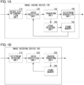
- the image coding device 100 includes a block size determination unit 110, an inter prediction unit 120, a transform unit 130, a bitstream generation unit 140, a local decoding unit 150, and a frame memory 160.
- the image coding device 100 receives an input of an input image, performs intra prediction and inter prediction, and outputs a bitstream.
- an image and a picture are used as meaning the same thing.
- the image coding device 100 and the image decoding device 200 are implemented by hardware such as an information processing device provided with a central processing unit (CPU), a memory, etc.
- CPU central processing unit
- memory etc.
- the block size determination unit 110 determines the block size subject to inter prediction, based on the input image.
- the block size determination unit 110 supplies the determined block size, block position, and input pixel (input value) corresponding to the block size to the inter prediction unit 120.
- rate distortion optimization RDO
- HEVC reference software etc. is used for determination of the block size.
- the inter prediction unit 120 uses the information input from the block size determination unit 110 and the reference picture input from the frame memory 160 to determine an inter prediction parameter used in inter prediction.
- the inter prediction unit 120 performs inter prediction based on the inter prediction parameter to derive a prediction value.
- the inter prediction unit 120 supplies the block size, block position, input value, inter prediction parameter, and prediction value to the transform unit 130.
- rate distortion optimization (RDO) used in HEVC reference software, etc. is used. The detail of the inter prediction parameter and the operation of the inter prediction unit 120 will be described later.
- the transform unit 130 calculates a difference value by subtracting the prediction value from the input value, calculates prediction error data by subjecting the calculated difference value to orthogonal transform, quantization, etc.
- the transform unit 130 supplies the block size, block position, inter prediction parameter, the prediction error data to the bitstream generation unit 140 and the local decoding unit 150.
- the frame memory 160 stores a plurality of decoded images and inter prediction parameters for the plurality of images.
- the frame memory 160 supplies the decoded images and the inter prediction parameters to the inter prediction unit 120.
- the inter prediction parameter includes a merge flag, a merge index, an availability flag for LX prediction, a motion vector for LX prediction, a reference picture index for LX prediction, a merge correction flag, and a motion vector difference for LX prediction.
- LX is L0 or L1.
- the merge flag is a flag indicating which of the merge mode and the motion vector difference mode is used as the inter prediction mode. When the merge flag is 1, the merge mode is used. When the merge flag is 0, the motion vector difference mode is used.
- the merge index is an index indicating the position of a selected merge candidate in the merge candidate list.
- the availability flag for LX prediction is a flag indicating whether LX prediction is available or unavailable.
- the picture type of a B picture for which all of unidirectional L0 prediction, unidirectional L1 prediction, and bidirectional prediction are available, is described by way of example.
- the picture type may be a P picture, for which only unidirectional prediction is available.
- the inter prediction parameter for a P picture covers only L0 prediction and is processed such that L1 prediction is not available.
- the coding efficiency of B pictures is generally improved when the reference picture for L0 prediction is a picture in the past relative to the picture subject to prediction, and the reference picture for L1 prediction is a picture in the future relative to the picture subject to prediction.
- interpolative prediction improves the coding efficiency when the reference picture for L0 prediction and the reference picture for L1 prediction are located in opposite directions as viewed from the picture subject to prediction.
- Whether the reference picture for L0 prediction and the reference picture for L1 prediction are located in opposite directions as viewed from the picture subject to prediction can be determined by comparing the Picture Order Counts (POC) of the reference pictures.
- POC Picture Order Counts
- inter prediction unit 120 A description will now be given of the detail of the inter prediction unit 120. Unless otherwise specified, the configuration and operation of the inter prediction unit 120 of the image coding device and those of the inter prediction unit 220 of the image decoding device 200 are the same.
- Fig. 3 is a diagram for explaining the configuration of the inter prediction unit 120.
- the inter prediction unit 120 includes a merge mode determination unit 121, a merge candidate list generation unit 122, a merge candidate selection unit 123, a merge candidate correction determination unit 124, a merge candidate correction unit 125 a motion vector difference mode execution unit 126, and a prediction value derivation unit 127.
- the inter prediction unit 120 switches the inter prediction mode for each block by switching between the merge mode and the motion vector difference mode.
- the motion difference vector mode executed in the motion vector difference mode execution unit 126 is assumed to be executed as defined in HEVC, and a description will mainly be given below of the merge mode.
- the merge mode determination unit 121 determines for each block whether the merge mode is used as the inter prediction mode. When the merge flag is 1, the merge mode is used. When the merge flag is 0, the motion vector difference mode is used.
- the inter prediction unit 220 acquires the merge flat decoded by the bitstream decoding unit 210 from the bitstream based on the syntax. The detail of the syntax will be described later.
- the motion vector difference mode execution unit 126 executes the motion vector difference mode, and the inter prediction parameter in the motion vector difference mode is supplied to the prediction value derivation unit 127.
- the merge mode is executed in the merge candidate list generation unit 122, the merge candidate selection unit 123, the merge candidate correction determination unit 124, and the merge candidate correction unit 125.
- the inter prediction parameter in the merge mode is supplied to the prediction value derivation unit 127.
- Fig. 5 is a diagram for explaining the configuration of the merge candidate list generation unit 122.
- the merge candidate list generation unit 122 includes a spatial merge candidate generation unit 201, a temporal merge candidate generation unit 202, and a merge candidate supplementing unit 203.
- Fig. 7 is a diagram for explaining blocks on the decoded image located at the same position as or around the block processed.
- a block CO1, a block CO2, and a block CO3 are defined as blocks located at the same position as or around the block processed.
- the embodiment is non-limiting so long as a plurality of blocks on the decoded image located at the same position as or around the block processed are used.
- the blocks CO1, CO2, and CO3 will be referred to as collocated blocks, and the decoded image including the collocated blocks will be referred to as the collocated picture.
- the spatial merge candidate generation unit 201 examines the block A, the block B, the block C, the block D, the block E, the block F, and the block G sequentially. When one or both of the availability flag for L0 prediction and the availability flag for L1 prediction indicates "available", the motion information on the block is added to the merge candidate list sequentially.
- the merge candidate generated by the spatial merge candidate generation unit 201 will be referred to as a spatial merge candidate.
- the temporal merge candidate generation unit 202 then examines the block CO01, the block CO2, and the block CO3 sequentially.
- the temporal merge candidate generation unit 202 subjects the motion information on the first block, for which one or both of the the availability flag for L0 prediction and the availability flag for L1 prediction indicates "available", to a process such as scaling and adds the block to the merge candidate list sequentially.
- the merge candidate generated by the temporal merge candidate generation unit 202 will be referred to as a temporal merge candidate.
- the merge candidate correction determination unit 124 sets a merge correction flag (S103) and supplies the merge correction flag to the merge candidate correction unit 125.
- the inter prediction unit 120 of the image coding device 100 sets the merge correction flag to 1 when the prediction error that results when inter prediction is performed by using the merge candidate is equal to larger than a predetermined prediction error.
- the inter prediction unit 120 sets the merge correction flag to 0.
- the inter prediction unit 220 of the image decoding device 200 acquires the merge correction flag decoded by the bitstream decoding unit 210 from the bitstream based on the syntax.
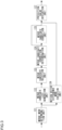
- the merge candidate correction unit 215 examines whether L0 prediction of the selected merge candidate is available (S105). When L0 prediction of the selected merge candidate indicates is not available (NO in S105), control proceeds to step S108. When L0 prediction of the selected merge candidate is available (YES in S105), the motion vector difference for L0 prediction is determined (S106). As described above, the motion information of the selected merge candidate is corrected when the merge correction flag is 1. The motion information of the selected merge candidate is not corrected when the merge correction flag is 0.
- the inter prediction unit 120 of the image coding device 100 determines the motion vector difference for L0 prediction through motion vector search. It is assumed here that the range searched for the motion vector is ⁇ 16 both in the horizontal direction and in the vertical direction. Alternatively, the range may be an integral multiple of 2 such as 64.
- the inter prediction unit 220 of the image decoding device 200 acquires the motion vector difference for L0 prediction decoded by the bitstream decoding unit 210 from the bitstream based on the syntax.
- the merge candidate correction unit 125 then calculates a corrected motion vector for L0 prediction and defines the corrected motion vector for L0 prediction as the motion vector for L0 prediction of the motion information on the block processed (S107).
- the corrected motion vector for L0 prediction (mvL0) is derived by adding the motion vector for L0 prediction of the selected merge candidate (mmvL0) and the motion vector difference for L0 prediction (mvdL0) and is given by the following expression, where [0] denotes the horizontal component of the motion vector, and [1] denotes the vertical component of the motion vector.
- L1 prediction of the selected merge candidate is available (S108).
- L1 prediction of the selected merge candidate is not available (NO in S108)
- control proceeds to step S111.
- L1 prediction of the selected merge candidate is available (YES in S108)
- the motion vector difference for L1 prediction is determined (S109).
- the corrected motion vector for L1 prediction (mvL1) is derived by adding the motion vector for L1 prediction of the selected merge candidate (mmvL1) and the motion vector difference for L1 prediction (mvdL1) and is given by the following expression, where [0] denotes the horizontal component of the motion vector, and [1] denotes the vertical component of the motion vector.
- mvL 1 0 mmvL 1 0 + mvdL 1 0
- mvL 1 1 mmvL 1 1 + mvdL 1 1 1 1
- Fig. 8 shows a part of the syntax of the block in the merge mode.
- Table 1 shows the relationship between the inter prediction parameter and the syntax.
- cbWidth of Fig. 8 denotes the width of the block processed, and cbheight denotes the height of the block processed.
- the predetermined with and the predetermined height are both defined to be 8. By not correcting the merge candidate in units of small blocks by setting the predetermined width and the predetermined height, the processing volume can be reduced.
- cu_skip_flag will be 1 when the block is in the skip mode and will be 0 when the block is not in the skip mode.
- the syntax of the skip mode is the same as the syntax of the merge mode.
- merge_idx is a merge index for selecting the selected merge candidate from the merge candidate list.
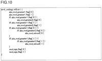
- Fig. 9 shows the syntax of the motion vector difference.
- mvd_coding(N) of Fig. 9 is the same syntax as the syntax used in the motion vector difference mode, where N is 0 or 1.
- the merge mode and the motion vector difference mode are available as inter prediction modes.
- the merge mode makes it possible to restore the motion information by using one merge flag and so offers an extremely high coding efficiency. Since the motion information in the merge mode depends on the processed block so that a high prediction efficiency is available only in limited cases, and improvement in the use efficiency has been called for.
- the motion vector difference mode requires preparing the syntax for L0 prediction and the syntax for L1 prediction separately.
- the motion vector difference mode also requires the prediction type (L0 prediction, L1 prediction, or bidirectional prediction) and the motion vector predictor flag, the motion vector difference, and the reference picture index for L0 prediction and L1 prediction, respectively. Therefore, the motion vector difference mode is a mode that does not offer a better coding efficiency than the merge mode but offers a stable and high prediction efficiency for abrupt motion that has little correlation to the motion of a spatially neighboring block or a temporally neighboring block, which cannot be derived in the merge mode.
- the coding efficiency can be improved from that of the motion vector difference mode and the use efficiency can be improved from that of the merge mode, by making it possible to correct the motion vector in the merge mode while maintaining the prediction type and the reference picture index of the merge mode fixed.
- the motion vector difference is restricted to a small magnitude and the coding efficiency is improved by defining the motion vector difference to be a difference from the motion vector of the selected merge candidate.
- configuring the syntax of the motion vector difference in the merge mode to be the same as the syntax of the motion vector difference in the motion vector difference mode requires only a small change in the configuration even if the motion vector difference is introduced in the merge mode.
- the processing volume required to correct the motion vector in the merge mode can be suppressed by defining the predetermined width and the predetermined height, and by skipping the process of correcting the motion vector in the merge mode unless it is satisfied that the prediction block width is equal to or larger than the predetermined with, the prediction block height is equal to larger than the predetermined height, and both or at least one of L0 prediction or L1 prediction of the selected merge candidate is available. It should be noted that there is no need to restrict the correction of the motion vector according to the predetermined width and the predetermined height if it is not necessary to suppress the processing volume for correcting the motion vector.
- the motion vector difference is used as the syntax of the block in the merge mode.
- the motion vector difference is defined to be coded (decoded) as a unit motion vector difference.
- a unit motion vector difference is a motion vector that results when the picture interval is the minimum interval. In HEVC, etc. the minimum picture interval is coded in the bitstream.
- abs_mvd_pow_plus2[d] is used instead of the syntax abs_mvd_minus3[d] according to variation 2.
- the motion vector difference mvd[d] is calculated from mvd_sign_flag[d] and abs_mvd_pow_plus2[d] according to the following expression.
- mvd d mvd_sign_flag d * 2 ⁇ abs_mvd_pow_plus 2 d + 2
- the prediction efficiency in the case of a large motion vector can be improved, while at the same time reducing the processing volume in the coding device significantly.
- the syntax mvd_coding(N) does not include abs_mvd_greater0_flag[d], abs_mvd_greater1_flag[d], or mvd_sign_flag[d] but is configured to include abs_mvr_plus2[d] and mvr_sign_flag[d] instead.
- the prediction efficiency in the case of a large motion vector can be improved, while at the same time reducing the processing volume in the coding device significantly.
- Fig. 8 indicates that merge_mod_flag is included in the case cu_skip_flag is 1 (skip mode). Alternatively, merge_mod_flag may not be included in the case of the skip mode.
- merge_mod_flag By omitting merge_mod_flag in this way, the coding efficiency in the skip mode can be improved, and the determination in the skip mode is simplified.
- the motion vector difference may be made available regardless of whether LN prediction of the selected merge candidate is available or not without examining whether LN prediction of the selected merge candidate is available. In this case, the motion vector of the selected merge candidate for LN prediction will be (0,0), and the reference picture index of the selected merge candidate for LN prediction will be 0, provided that LN prediction of the selected merge candidate is unavailable.
- the availability of L0 prediction and L1 prediction of the selected merge candidate is determined individually to control whether to code (decode) the motion vector difference.
- the motion vector difference may be coded (or decoded) when both L0 prediction and L1 prediction of the selected merge candidate are available and not coded (or decoded) when either L0 prediction or L1 prediction of the selected merge candidate is unavailable.
- step S102 will be as follows.
- the merge candidate correction determination unit 124 examines whether the width of the block processed is equal to or larger than the predetermined width, the height of the block processed is equal to or larger than the predetermined height, and both L0 prediction and L1 prediction of the selected merge candidate are available (S102).
- step S105 and step S108 are unnecessary in this variation.
- Fig. 11 shows a part of the syntax of the block in the merge mode according to variation 7.
- the syntax related to steps S102, S105, and S108 differs from that of the embodiment.
- two motion vector differences including the motion difference for L0 prediction and the motion vector difference for L1 prediction are used in the syntax of the block in the merge mode.
- the motion vector for L0 prediction is calculated according to the following expression.
- mvL 0 0 mmvL 0 0 + mvd 0
- mvL 0 1 mmvL 0 1 + mvd 1
- the motion vector for L1 prediction is calculated according to the following expression.
- the motion vector difference in the direction opposite to that of L0 prediction is added.
- the motion vector difference may be subtracted from the motion vector of the selected merge candidate for L1 prediction.
- Fig. 12 shows a part of the syntax of the block in the merge mode according to variation 8. This variation differs from the embodiment in that examination as to the availability of L0 prediction and the availability of L1 prediction is removed, and mvd_coding(1) is not included. mvd_coding(0) represents the one motion vector difference.
- the coding efficiency can be improved while at the same time inhibiting the prediction efficiency from dropping according to this variation, by defining only one motion vector difference for L0 prediction and L1, thereby reducing the number of motion vector differences to half in the case of bidirectional prediction and sharing one motion vector difference for L0 prediction and L1 prediction.
- the coding efficiency in the presence of a motion in a certain direction can be improved by adding, when the reference picture referred to by the selected merge candidate for L0 prediction and the reference picture referred to for L1 prediction are located in opposite directions (are not in the same direction) with respect to the picture subject to prediction, the motion vector difference in the opposite direction.
- Fig. 16 is a diagram for explaining the advantage of variation 8.
- Fig. 16 shows an image of a sphere (area filled by hatched lines) moving in the horizontal direction in a moving rectangular area (area bounded by the broken line).
- the motion of the sphere relative to the screen will be derived by adding the motion of the rectangular area and the motion of the sphere moving in the horizontal direction.
- picture B is the picture subject to prediction
- picture A is the reference picture for L0 prediction
- picture C is the reference picture for L1 prediction.
- Picture A and picture B are reference pictures located in opposite directions with respect to the picture subject to prediction.
- the motion of the sphere can be accurately reproduced by adding the amount of motion of the sphere that cannot be acquired from adjacent blocks to L0 prediction and subtracting the amount from L1 prediction, provided that picture A, picture B, and picture C are at equal intervals.
- the motion of the sphere can be accurately reproduced by adding the amount of motion of the sphere that cannot be acquired from adjacent blocks to L0 prediction and subtracting the amount from L1 prediction, provided that picture A, picture B, and picture C are not at equal intervals but the amounts of motion of the sphere relative to the rectangular area are at equal intervals.
- FIG. 17 is a diagram for explaining the advantage achieved in the case the picture intervals of variation 8 are not constant. A detailed description of this case will be given with reference to Fig. 17 .
- Pictures F0, F1, ..., F8 of Fig. 17 are pictures at fixed intervals. It is assumed that, from picture F0 to picture F4, the sphere remains still and moves in a constant direction at a constant speed from picture F5 forward.
- picture F0 and picture F6 are reference pictures and picture F5 is the picture subject to prediction
- picture F0, picture F5, and picture F6 are not at equal intervals, but the amounts of motion of the sphere relative to the rectangular area are at equal intervals.
- picture F5 as the picture subject to prediction
- the closest picture F4 is generally selected as the reference picture.
- Picture F0 will be selected as the reference picture instead of picture F4 if picture F0 is a high-quality picture less distorted than picture F4.
- the reference picture is normally managed in the First-In First-Out (FIFO) scheme in the reference picture buffer.
- FIFO First-In First-Out
- the long term reference picture is available as a scheme to allow a high-quality, less-distorted picture to remain in the reference picture buffer for a long time as a reference picture.
- the long-term reference picture is not managed in the FIFO scheme in the reference picture buffer.
- Reference picture list control information coded in the slice header manages whether to define a picture as a long-term reference picture.
- the prediction efficiency and the coding efficiency can be improved by applying this variation to the case in which one or both of L0 prediction and L1 prediction uses a long-term reference picture.
- the prediction efficiency and the coding efficiency can be improved by applying this variation to the case in which an intra picture is encountered in one or both of L0 prediction and L1 prediction.
- the circuit scale and power consumption can be reduced by not scaling the motion vector difference based on the inter-picture distance as in the case of the temporal merge candidate. If the temporal merge candidate is selected as the selected merge candidate in the case the motion vector difference is scaled, for example, scaling of the temporal merge candidate and scaling of the motion vector and scaling of the motion vector difference will both be required. Scaling of the temporal merge candidate and scaling of the motion vector differ are based on different reference motion vectors and so cannot be performed concurrently and must be performed separately.
- the temporal merge candidate is included in the merge candidate list as in the case of the embodiment, the temporal merge candidate is scaled, and the coding efficiency can be improved without scaling the motion vector difference provided that the motion vector difference is smaller than the motion vector of the temporal merge candidate. Further, the coding efficiency is inhibited from dropping by selecting the motion vector difference mode when the motion vector difference is large.
- the maximum number of merge candidates in the case of the merge correction flag of 1 is configured to be smaller than the maximum number of merge candidates in the case of the merge correction flag of 0.
- the maximum number of merge candidates is defined to be 2 when the merge correction flag is 1.
- the maximum number of merge candidates in the case of the merge correction flag of 1 will be referred to as maximum number of corrected merge candidates.
- the merge correction flag is coded (decoded).
- the merge correction flag is not coded (decoded).
- the maximum number of merge candidates and the maximum number of corrected merge candidates in the case of the merge correction flag of 0 may be predefined or coded in the SPS or PPS in the bitstream and acquired therefrom.
- this variation curtails the process in the coding device and, at the same, inhibits the coding efficiency from dropping by determining whether or not to correct the merge candidate mode only in the case of the merge candidate that is relatively more likely to be selected, by configuring the maximum number of merge candidates in the case of the merge correction flag of 1 to be smaller than the maximum number of merge candidates in the case of the merge correction flag of 0. Since this makes it unnecessary to code (decode) the merge correction flag when the merge index is equal to or larger than the maximum number of corrected merge candidates, the coding efficiency is improved.
- the configuration of the image coding device 100 and the image decoding device 200 according to the second embodiment is the same as that of the image coding device 100 and the image decoding device 200 according to the first embodiment.
- the second embodiment differs from the first embodiment in respect of the operation and syntax in the merge mode. A description will now be given of the difference between the second embodiment and the first embodiment.
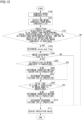
- Fig. 13 is a flowchart for explaining the operation in the merge mode according to the second embodiment.
- Fig. 14 shows a part of the syntax of the block in the merge mode according to the second embodiment.
- Fig. 15 shows the syntax of the motion vector difference according to the second embodiment.
- Fig. 13 differs from Fig. 4 in respect of steps S205 through S207 and steps S109 through S211.
- the inter prediction unit 120 of the image coding device 100 determines the corrected motion vector for L0 prediction through motion vector search. It is assumed here that the range searched for the motion vector is ⁇ 1 both in the horizontal direction and in the vertical direction.
- the inter prediction unit 220 of the image decoding device 200 acquires the corrected motion vector for L0 prediction from the bitstream.
- the reference picture index for L0 prediction is then determined (S207). It is assumed here that the reference picture index for L0 prediction is 0.
- Whether the slice type is B and L1 prediction of the selected merge candidate is unavailable is examined (S208).
- the slice type is not B or L1 prediction of the selected merge candidate is not unavailable (NO in S208)
- control proceeds to S111.
- the slice type is not B and L1 prediction of the selected merge candidate is unavailable (YES in S208)
- the corrected motion vector for L1 prediction is determined (S209).
- the inter prediction unit 120 of the image coding device 100 determines the corrected motion vector for L1 prediction through motion vector search. It is assumed here that the range searched for the motion vector is ⁇ 1 both in the horizontal direction and in the vertical direction.
- the inter prediction unit 220 of the image decoding device 200 acquires the corrected motion vector for L1 prediction from the bitstream.
- the reference picture index for L1 prediction is then determined (S110). It is assumed here that the reference picture index for L1 prediction is 0.
- the merge candidate of L0 prediction or L1 prediction is converted in this embodiment into the merge candidate of bidirectional prediction, when the slice type is a type that permits bidirectional prediction (i.e., the slice type B). Conversion into the merge candidate of bidirectional prediction makes it possible to expect improvement in the prediction efficiency provided by the filtering effect. Also, by using the immediately neighboring decoded image as the reference picture, the range searched for the motion vector is controlled to be minimum.
- the reference picture index in step S207 and step 210 is defined to be 0.
- the reference picture index for L0 prediction is defined to be the reference picture index for L1 prediction when L0 prediction of the selected merge candidate is unavailable.
- the reference picture index for L1 prediction is defined to be the reference picture index for L0 prediction when L1 prediction of the selected merge candidate is unavailable.
- the bitstream output by the image coding device has a specified data format so that the bitstream can be decoded according to the coding method used in the embodiments.
- the bitstream may be stored in a recording medium such as HDD, SSD, flash memory, and optical disk that can be read from a computer etc. and provided accordingly.
- the bitstream may be made provided from a server via a wired or wireless network. Accordingly, the image decoding device compatible with the image coding device can decode the bitstream of the specified data format regardless of the means of provision.
- the bitstream may be transformed into a data format suited to the transmission mode of the communication channel and transmitted accordingly.
- a transmission device that transforms the bitstream output by the image coding device into coded data of a data format suited to the transmission mode of the communication channel and a reception device that receives the coded data from the network, restoring the bitstream, and supplying the bitstream to the image decoding device are provided.
- the transmission device includes a memory that buffers the bitstream output by the image coding device, a packet processing unit that packetizes the bitstream, and a transmission unit that transmits the packetized coded data via the network.
- the reception device includes a reception unit that receives the packetized coded data via the network, a memory that buffers the received coded data, and a packet processing unit that subjects the coded data to a packet process to generate the bitstream and provides the bitstream to the image decoding device.
- a relay device that receives the bitstream data transmitted by the transmission device and supplies the data to the reception device may be provided in addition to the transmission device and the reception device.
- the relay device includes a reception unit that receives the packetized coded data transmitted by the transmission device, a memory that buffers the coded data received, and a transmission unit that transmits the packetized coded data to the network.
- the relay device may further include a received packet processing unit that subjects the packetized coded data to a packet process to generate the bitstream, a recording medium that stores the bitstream, and a transmission packet processing unit that packetizes the bitstream.
- a display device may be provided by adding a display unit that displays the image decoded by the image decoding device.
- an imaging device may be provided by adding an imaging unit and inputting the captured image to the image coding device.
- Fig. 18 shows an exemplary hardware configuration of the coding and decoding device of the present application.
- the coding and decoding device includes the configurations of the image coding device and the image decoding device according to the embodiments.
- a coding and decoding device 9000 includes a CPU 9001, a codec IC 9002, an I/O interface 9003, a memory 9004, an optical disk drive 9005, a network interface 9006, and a video interface 9009. The parts are connected by a bus 9010.
- An image coding unit 9007 and an image decoding unit 9008 are typically implemented as the codec IC 9002.
- the image coding process of the image coding device according to the embodiments is executed by the image coding unit 9007, and the image decoding process of the image decoding device according to the embodiments is executed by the image coding unit 9007.
- the I/O interface 9003 is implemented by, for example, a USB interface and is connected to an external keyboard 9104, a mouse 9105, etc.
- the CPU 9001 controls the coding and decoding device 9000 to perform the process desired by the user, based on the user operation input via the I/O interface 9003.
- the user operation via the keyboard 9104, the mouse 9105, etc. includes the selection of either coding or decoding, setting of the coding quality, input and output destinations of the bitstream, input and output destinations of the image, etc.
- the optical disk drive 9005 reads the bitstream from the inserted disk recording medium 9100 and sends the bitstream thus read to the image decoding unit 9008 of the codec IC 9002 via the bus 9010.
- the image decoding unit 9008 subjects the input bitstream to the image decoding process in the image decoding device according to the embodiments and sends the decoded image to an external monitor 9103 via a video interface 9009.
- the coding and decoding device 9000 has a network interface 9006 and can be connected to an external distribution server 9106 or a mobile terminal 9107 via a network 9101.
- the network interface 9006 acquires the bitstream from the network 9101 instead of reading the bitstream from the input disk recording medium 9100.
- the bitstream recorded in the memory 9004 is subject to the image decoding process in the image decoding device according to the embodiments.
- the video interface 9009 receives the image from the camera 9102 and sends the image to the image coding unit 9007 of the codec IC 9002 via the bus 9010.
- the image coding unit 9007 subjects the image input via the video interface 9009 to the image coding process in the image coding device according to the embodiments to generate the bitstream.
- the image coding unit 9007 sends the bitstream to the memory 9004 via the bus 9010.
- the optical disk drive 9005 writes the bitstream in the inserted disk recording medium 9100.
- Such hardware configuration is implemented by, for example, replacing the codec IC 9002 by the image coding unit 9007 or the image decoding unit 9008, respectively.
- the above-described processes related to coding and decoding can of course be implemented as a transfer device, storage device, reception device in which hardware such as ASIC is used and can also be implemented by firmware stored in a read-only memory (ROM), a flash memory, etc. or by software for a CPU, a System On Chip (SOC) computer, etc.
- the firmware program or the software program may be recorded on a recording medium that can be read from, for example, a computer and provided accordingly.
- the program may be made available from a server via a wired or wireless network.
- the program may be made available in the form of data broadcast over terrestrial or satellite digital broadcast systems.
- the present invention can be used in image decoding technology.
- 100 image coding device 110 block size determination unit, 120 inter prediction unit, 121 merge mode determination unit, 122 merge candidate list generation unit, 123 merge candidate selection unit, 124 merge candidate correction determination unit, 125 merge candidate correction unit, 126 motion vector difference mode execution unit, 127 prediction value calculation unit, 130 transform unit, 140 bitstream generation unit, 150 local decoding unit, 160 frame memory, 200 image decoding device, 201 spatial merge candidate generation unit 202 temporal merge candidate generation unit, 203 merge candidate supplementing unit, 210 bitstream decoding unit, 220 inter prediction unit, 230 inverse transform unit, 240 frame memory
Landscapes
- Engineering & Computer Science (AREA)
- Multimedia (AREA)
- Signal Processing (AREA)
- Compression Or Coding Systems Of Tv Signals (AREA)
Claims (6)
- Eine Bilddecodiervorrichtung, aufweisend:eine Mergingkandidatenliste-Erzeugungseinheit, die eine Mergingkandidatenliste generiert, die als einen Mergingkandidaten einen Raummergingkandidaten, der Bewegungsinformationen zu einer Vielzahl von Blöcken in Nachbarschaft zu einem einer Prädiktion unterworfenen Block aufweist, und einen Zeitmergingkandidaten, der Bewegungsinformationen mit einem durch das Skalieren eines Bewegungsvektors eines Blocks eines decodierten Bilds an der gleichen Position wie der einer Prädiktion unterworfene Block erhaltenen Bewegungsvektor aufweist, enthält,eine Mergingkandidaten-Auswahleinheit, die als einen ausgewählten Mergingkandidaten, der eine Bewegungsinformation des einer Prädiktion unterworfenen Blocks ist, einen Mergingkandidaten aus der Mergingkandidatenliste auswählt,eine Bitstrom-Decodiereinheit, die einen Bitstrom decodiert, um ein Mergingkorrektur-Flag, das angibt, ob der Mergingkandidat korrigiert werden soll, und eine Bewegungsvektordifferenz, die für einen Bewegungsvektor des ausgewählten Mergingkandidaten für eine erste Prädiktion und einen Bewegungsvektor des ausgewählten Mergingkandidaten für eine zweite Prädiktion gemeinsam ist, abzuleiten, wenn das Mergingkorrektur-Flag angibt, dass der Mergingkandidat korrigiert ist, undeine Mergingkandidat-Korrektureinheit, die einen korrigierten Mergingkandidaten einer bidirektionalen Prädiktion ableitet durch das Addieren der Bewegungsvektordifferenz zu einem Bewegungsvektor des ausgewählten Mergingkandidaten für eine erste Prädiktion und das Subtrahieren der Bewegungsvektordifferenz von einem Bewegungsvektor des ausgewählten Mergingkandidaten für eine zweite Prädiktion, wenn das Mergingkorrektur-Flag angibt, dass der Mergingkandidat korrigiert ist, und ein Referenzbild des ausgewählten Mergingkandidaten für eine erste Prädiktion oder ein Referenzbild des ausgewählten Mergingkandidaten für eine zweite Prädiktion ein langfristiges Referenzbild ist, wobei der korrigierte Mergingkandidat von dem Bewegungsvektor des ausgewählten Mergingkandidaten für die erste Prädiktion und dem Bewegungsvektor des ausgewählten Mergingkandidaten für die zweite Prädiktion, der verschieden von dem Bewegungsvektor des ausgewählten Mergingkandidaten für die erste Prädiktion ist, abgeleitet wird.
- Ein Bilddecodierverfahren, aufweisend:Generieren einer Mergingkandidatenliste, die als einen Mergingkandidaten einen Raummergingkandidaten, der Bewegungsinformationen zu einer Vielzahl von Blöcken in Nachbarschaft zu einem einer Prädiktion unterworfenen Block aufweist, und einen Zeitmergingkandidaten, der Bewegungsinformationen mit einem durch das Skalieren eines Bewegungsvektors eines Blocks eines decodierten Bilds an der gleichen Position wie der einer Prädiktion unterworfene Block erhaltenen Bewegungsvektor aufweist, enthält,Auswählen, als eines ausgewählten Mergingkandidaten, der eine Bewegungsinformation des einer Prädiktion unterworfenen Blocks ist, eines Mergingkandidaten aus der Mergingkandidatenliste,Decodieren eines Bitstroms, um ein Mergingkorrektur-Flag, das angibt, ob der Mergingkandidat korrigiert werden soll, und eine Bewegungsvektordifferenz, die für einen Bewegungsvektor des ausgewählten Mergingkandidaten für eine erste Prädiktion und einen Bewegungsvektor des ausgewählten Mergingkandidaten für eine zweite Prädiktion gemeinsam ist, abzuleiten, wenn das Mergingkorrektur-Flag angibt, dass der Mergingkandidat korrigiert ist, undAbleiten eines korrigierten Mergingkandidaten einer bidirektionalen Prädiktion durch das Addieren der Bewegungsvektordifferenz zu einem Bewegungsvektor des ausgewählten Mergingkandidaten für eine erste Prädiktion und das Subtrahieren der Bewegungsvektordifferenz von einem Bewegungsvektor des ausgewählten Mergingkandidaten für eine zweite Prädiktion, wenn das Mergingkorrektur-Flag angibt, dass der Mergingkandidat korrigiert ist, und ein Referenzbild des ausgewählten Mergingkandidaten für eine erste Prädiktion oder ein Referenzbild des ausgewählten Mergingkandidaten für eine zweite Prädiktion ein langfristiges Referenzbild ist, wobei der korrigierte Mergingkandidat von dem Bewegungsvektor des ausgewählten Mergingkandidaten für die erste Prädiktion und dem Bewegungsvektor des ausgewählten Mergingkandidaten für die zweite Prädiktion, der verschieden von dem Bewegungsvektor des ausgewählten Mergingkandidaten für die erste Prädiktion ist, abgeleitet wird.
- Ein Bilddecodierprogramm, das computerimplementierte Module umfasst, aufweisend:ein Modul, das eine Mergingkandidatenliste generiert, die als einen Mergingkandidaten einen Raummergingkandidaten, der Bewegungsinformationen zu einer Vielzahl von Blöcken in Nachbarschaft zu einem einer Prädiktion unterworfenen Block aufweist, und einen Zeitmergingkandidaten, der Bewegungsinformationen mit einem durch das Skalieren eines Bewegungsvektors eines Blocks eines decodierten Bilds an der gleichen Position wie der einer Prädiktion unterworfene Block erhaltenen Bewegungsvektor aufweist, enthält,ein Modul, das als einen ausgewählten Mergingkandidaten, der eine Bewegungsinformation des einer Prädiktion unterworfenen Blocks ist, einen Mergingkandidaten aus der Mergingkandidatenliste auswählt,ein Modul, das einen Bitstrom decodiert, um ein Mergingkorrektur-Flag, das angibt, ob der Mergingkandidat korrigiert werden soll, und eine Bewegungsvektordifferenz, die für einen Bewegungsvektor des ausgewählten Mergingkandidaten für eine erste Prädiktion und einen Bewegungsvektor des ausgewählten Mergingkandidaten für eine zweite Prädiktion gemeinsam ist, abzuleiten, wenn das Mergingkorrektur-Flag angibt, dass der Mergingkandidat korrigiert ist, undein Modul, das einen korrigierten Mergingkandidaten einer bidirektionalen Prädiktion ableitet durch das Addieren der Bewegungsvektordifferenz zu einem Bewegungsvektor des ausgewählten Mergingkandidaten für eine erste Prädiktion und das Subtrahieren der Bewegungsvektordifferenz von einem Bewegungsvektor des ausgewählten Mergingkandidaten für eine zweite Prädiktion, wenn das Mergingkorrektur-Flag angibt, dass der Mergingkandidat korrigiert ist, und ein Referenzbild des ausgewählten Mergingkandidaten für eine erste Prädiktion oder ein Referenzbild des ausgewählten Mergingkandidaten für eine zweite Prädiktion ein langfristiges Referenzbild ist, wobei der korrigierte Mergingkandidat von dem Bewegungsvektor des ausgewählten Mergingkandidaten für die erste Prädiktion und dem Bewegungsvektor des ausgewählten Mergingkandidaten für die zweite Prädiktion, der verschieden von dem Bewegungsvektor des ausgewählten Mergingkandidaten für die erste Prädiktion ist, abgeleitet wird.
- Eine Bildcodiervorrichtung, aufweisend:eine Mergingkandidatenliste-Erzeugungseinheit, die eine Mergingkandidatenliste generiert, die als einen Mergingkandidaten einen Raummergingkandidaten, der Bewegungsinformationen zu einer Vielzahl von Blöcken in Nachbarschaft zu einem einer Prädiktion unterworfenen Block aufweist, und einen Zeitmergingkandidaten, der Bewegungsinformationen mit einem durch das Skalieren eines Bewegungsvektors eines Blocks eines codierten Bilds an der gleichen Position wie der einer Prädiktion unterworfene Block erhaltenen Bewegungsvektor aufweist, enthält,eine Mergingkandidaten-Auswahleinheit, die als einen ausgewählten Mergingkandidaten, der eine Bewegungsinformation des einer Prädiktion unterworfenen Blocks ist, einen Mergingkandidaten aus der Mergingkandidatenliste auswählt,eine Mergingkandidatenkorrektur-Bestimmungseinheit, die ein Mergingkorrektur-Flag, das angibt, ob der Mergingkandidat korrigiert werden soll, setzt,eine Mergingkandidaten-Korrektureinheit, die einen korrigierten Mergingkandidaten einer bidirektionalen Prädiktion ableitet durch das Addieren einer Bewegungsvektordifferenz zu einem Bewegungsvektor des ausgewählten Mergingkandidaten für eine erste Prädiktion und das Subtrahieren der Bewegungsvektordifferenz von einem Bewegungsvektor des ausgewählten Mergingkandidaten für eine zweite Prädiktion, wenn das Mergingkorrektur-Flag angibt, dass der Mergingkandidat korrigiert ist, und ein Referenzbild des ausgewählten Mergingkandidaten für eine erste Prädiktion oder ein Referenzbild des ausgewählten Mergingkandidaten für eine zweite Prädiktion ein langfristiges Referenzbild ist, wobei der korrigierte Mergingkandidat von einem Bewegungsvektor des ausgewählten Mergingkandidaten für eine erste Prädiktion und einem Bewegungsvektor des ausgewählten Mergingkandidaten für eine zweite Prädiktion, der verschieden von dem Bewegungsvektor des ausgewählten Mergingkandidaten für die erste Prädiktion ist, abgeleitet wird, undeine Bitstrom-Codiereinheit, die das Mergingkorrektur-Flag und die Bewegungsvektordifferenz, die für den Bewegungsvektor des ausgewählten Mergingkandidaten für die erste Prädiktion und den Bewegungsvektor des ausgewählten Mergingkandidaten für die zweite Prädiktion gemeinsam ist, codiert, wenn das Mergingkorrektur-Flag angibt, dass der Mergingkandidat zu einem Bitstrom korrigiert ist.
- Ein Bildcodierverfahren, aufweisend:Generieren einer Mergingkandidatenliste, die als einen Mergingkandidaten einen Raummergingkandidaten, der Bewegungsinformationen zu einer Vielzahl von Blöcken in Nachbarschaft zu einem einer Prädiktion unterworfenen Block aufweist, und einen Zeitmergingkandidaten, der Bewegungsinformationen mit einem durch das Skalieren eines Bewegungsvektors eines Blocks eines codierten Bilds an der gleichen Position wie der einer Prädiktion unterworfene Block erhaltenen Bewegungsvektor aufweist, enthält,Auswählen, als eines ausgewählten Mergingkandidaten, der eine Bewegungsinformation des einer Prädiktion unterworfenen Blocks ist, eines Mergingkandidaten aus der Mergingkandidatenliste,Setzen eines Mergingkorrektur-Flags, das angibt, ob der Mergingkandidat korrigiert werden soll,Ableiten eines korrigierten Mergingkandidaten einer bidirektionalen Prädiktion durch das Addieren einer Bewegungsvektordifferenz zu einem Bewegungsvektor des ausgewählten Mergingkandidaten für eine erste Prädiktion und das Subtrahieren der Bewegungsvektordifferenz von einem Bewegungsvektor des ausgewählten Mergingkandidaten für eine zweite Prädiktion, wenn das Mergingkorrektur-Flag angibt, dass der Mergingkandidat korrigiert ist, und ein Referenzbild des ausgewählten Mergingkandidaten für eine erste Prädiktion oder ein Referenzbild des ausgewählten Mergingkandidaten für eine zweite Prädiktion ein langfristiges Referenzbild ist, wobei der korrigierte Mergingkandidat von einem Bewegungsvektor des ausgewählten Mergingkandidaten für eine erste Prädiktion und einem Bewegungsvektor des ausgewählten Mergingkandidaten für eine zweite Prädiktion, der verschieden von dem Bewegungsvektor des ausgewählten Mergingkandidaten für die erste Prädiktion ist, abgeleitet wird, undCodieren des Mergingkorrektur-Flags und der Bewegungsvektordifferenz, die für den Bewegungsvektor des ausgewählten Mergingkandidaten für die erste Prädiktion und den Bewegungsvektor des ausgewählten Mergingkandidaten für die zweite Prädiktion gemeinsam ist, wenn das Mergingkorrektur-Flag angibt, dass der Mergingkandidat zu einem Bitstrom korrigiert ist.
- Ein Bildcodierprogramm, das computerimplementierte Module umfasst, aufweisend:ein Modul, das eine Mergingkandidatenliste generiert, die als einen Mergingkandidaten einen Raummergingkandidaten, der Bewegungsinformationen zu einer Vielzahl von Blöcken in Nachbarschaft zu einem einer Prädiktion unterworfenen Block aufweist, und einen Zeitmergingkandidaten, der Bewegungsinformationen mit einem durch das Skalieren eines Bewegungsvektors eines Blocks eines codierten Bilds an der gleichen Position wie der einer Prädiktion unterworfene Block erhaltenen Bewegungsvektor aufweist, enthält,ein Modul, das als einen ausgewählten Mergingkandidaten, der eine Bewegungsinformation des einer Prädiktion unterworfenen Blocks ist, einen Mergingkandidaten aus der Mergingkandidatenliste auswählt,ein Modul, das ein Mergingkorrektur-Flag, das angibt, ob der Mergingkandidat korrigiert werden soll, setzt,ein Modul, das einen korrigierten Mergingkandidaten einer bidirektionalen Prädiktion ableitet durch das Addieren einer Bewegungsvektordifferenz zu einem Bewegungsvektor des ausgewählten Mergingkandidaten für eine erste Prädiktion und das Subtrahieren der Bewegungsvektordifferenz von einem Bewegungsvektor des ausgewählten Mergingkandidaten für eine zweite Prädiktion, wenn das Mergingkorrektur-Flag angibt, dass der Mergingkandidat korrigiert ist, und ein Referenzbild des ausgewählten Mergingkandidaten für eine erste Prädiktion oder ein Referenzbild des ausgewählten Mergingkandidaten für eine zweite Prädiktion ein langfristiges Referenzbild ist, wobei der korrigierte Mergingkandidat von einem Bewegungsvektor des ausgewählten Mergingkandidaten für eine erste Prädiktion und einem Bewegungsvektor des ausgewählten Mergingkandidaten für eine zweite Prädiktion, der verschieden von dem Bewegungsvektor des ausgewählten Mergingkandidaten für die erste Prädiktion ist, abgeleitet wird, undein Modul, das das Mergingkorrektur-Flag und die Bewegungsvektordifferenz, die für den Bewegungsvektor des ausgewählten Mergingkandidaten für die erste Prädiktion und den Bewegungsvektor des ausgewählten Mergingkandidaten für die zweite Prädiktion gemeinsam ist, codiert, wenn das Mergingkorrektur-Flag angibt, dass der Mergingkandidat zu einem Bitstrom korrigiert ist.
Priority Applications (1)
| Application Number | Priority Date | Filing Date | Title |
|---|---|---|---|
| EP25163949.8A EP4546782A3 (de) | 2018-12-13 | 2019-12-13 | Bilddecodierungsvorrichtung, bilddecodierungsverfahren und bilddecodierungsprogramm |
Applications Claiming Priority (3)
| Application Number | Priority Date | Filing Date | Title |
|---|---|---|---|
| JP2018233432 | 2018-12-13 | ||
| JP2019171782A JP6933235B2 (ja) | 2018-12-13 | 2019-09-20 | 画像復号装置、画像復号方法、及び画像復号プログラム |
| PCT/JP2019/048855 WO2020122224A1 (ja) | 2018-12-13 | 2019-12-13 | 画像復号装置、画像復号方法、及び画像復号プログラム |
Related Child Applications (1)
| Application Number | Title | Priority Date | Filing Date |
|---|---|---|---|
| EP25163949.8A Division EP4546782A3 (de) | 2018-12-13 | 2019-12-13 | Bilddecodierungsvorrichtung, bilddecodierungsverfahren und bilddecodierungsprogramm |
Publications (3)
| Publication Number | Publication Date |
|---|---|
| EP3896972A1 EP3896972A1 (de) | 2021-10-20 |
| EP3896972A4 EP3896972A4 (de) | 2022-04-20 |
| EP3896972B1 true EP3896972B1 (de) | 2025-04-09 |
Family
ID=71075651
Family Applications (2)
| Application Number | Title | Priority Date | Filing Date |
|---|---|---|---|
| EP19896609.5A Active EP3896972B1 (de) | 2018-12-13 | 2019-12-13 | Bilddekodierungsvorrichtung, bilddekodierungsverfahren, und bilddekodierungsprogramm |
| EP25163949.8A Pending EP4546782A3 (de) | 2018-12-13 | 2019-12-13 | Bilddecodierungsvorrichtung, bilddecodierungsverfahren und bilddecodierungsprogramm |
Family Applications After (1)
| Application Number | Title | Priority Date | Filing Date |
|---|---|---|---|
| EP25163949.8A Pending EP4546782A3 (de) | 2018-12-13 | 2019-12-13 | Bilddecodierungsvorrichtung, bilddecodierungsverfahren und bilddecodierungsprogramm |
Country Status (12)
| Country | Link |
|---|---|
| US (3) | US11758129B2 (de) |
| EP (2) | EP3896972B1 (de) |
| JP (1) | JP7318686B2 (de) |
| KR (2) | KR20250008140A (de) |
| CN (4) | CN116600108A (de) |
| CA (1) | CA3250456A1 (de) |
| CL (1) | CL2021001412A1 (de) |
| MX (2) | MX2021003506A (de) |
| MY (1) | MY199614A (de) |
| RU (1) | RU2770794C1 (de) |
| WO (1) | WO2020122224A1 (de) |
| ZA (1) | ZA202102033B (de) |
Families Citing this family (1)
| Publication number | Priority date | Publication date | Assignee | Title |
|---|---|---|---|---|
| KR20250176149A (ko) * | 2024-06-11 | 2025-12-18 | 주식회사 케이티 | 영상 부호화/복호화 방법 및 압축된 비디오 데이터를 전송하기 위한 장치 |
Family Cites Families (32)
| Publication number | Priority date | Publication date | Assignee | Title |
|---|---|---|---|---|
| JP3637996B2 (ja) | 1997-03-28 | 2005-04-13 | シャープ株式会社 | 領域統合が可能な動き補償フレーム間予測方式を用いた動画像符号化・復号化装置 |
| JP2002232892A (ja) * | 2001-02-01 | 2002-08-16 | Sony Corp | 画像符号化装置 |
| WO2012120870A1 (ja) * | 2011-03-08 | 2012-09-13 | 株式会社Jvcケンウッド | 動画像符号化装置、動画像符号化方法及び動画像符号化プログラム、並びに動画像復号装置、動画像復号方法及び動画像復号プログラム |
| US9247249B2 (en) * | 2011-04-20 | 2016-01-26 | Qualcomm Incorporated | Motion vector prediction in video coding |
| ES2769378T3 (es) * | 2011-05-27 | 2020-06-25 | Sun Patent Trust | Procedimiento de codificación de imágenes y aparato de codificación de imágenes |
| SG194746A1 (en) * | 2011-05-31 | 2013-12-30 | Kaba Gmbh | Image encoding method, image encoding device, image decoding method, image decoding device, and image encoding/decoding device |
| PL3879834T3 (pl) * | 2011-05-31 | 2024-07-29 | Jvckenwood Corporation | Urządzenie do kodowania ruchomego obrazu wizyjnego, sposób kodowania ruchomego obrazu wizyjnego i program do kodowania ruchomego obrazu wizyjnego, a także urządzenie do dekodowania ruchomego obrazu wizyjnego, sposób dekodowania ruchomego obrazu wizyjnego i program do dekodowania ruchomego obrazu wizyjnego |
| JP5786498B2 (ja) * | 2011-06-30 | 2015-09-30 | 株式会社Jvcケンウッド | 画像符号化装置、画像符号化方法及び画像符号化プログラム |
| KR102004113B1 (ko) * | 2011-06-30 | 2019-07-25 | 가부시키가이샤 제이브이씨 켄우드 | 화상 부호화 장치, 화상 부호화 방법, 화상 부호화 프로그램, 화상 복호 장치, 화상 복호 방법 및 화상 복호 프로그램 |
| KR101423648B1 (ko) * | 2011-09-09 | 2014-07-28 | 주식회사 케이티 | 화면 간 예측 수행시 후보 블록 결정 방법 및 이러한 방법을 사용하는 장치 |
| CN103348679B (zh) * | 2011-10-27 | 2017-05-24 | 太阳专利托管公司 | 图像解码方法及图像解码装置 |
| EP2773111B1 (de) | 2011-10-28 | 2020-01-01 | Sun Patent Trust | Bildverschlüsselungsverfahren, bildentschlüsselungsverfahren, bildverschlüsselungsvorrichtung und bildentschlüsselungsvorrichtung |
| BR112014016922B1 (pt) * | 2012-01-18 | 2023-01-31 | JVC Kenwood Corporation | Dispositivo e método de codificação de representação em movimento e dispositivo e método de decodificação de representação em movimento |
| US9426463B2 (en) * | 2012-02-08 | 2016-08-23 | Qualcomm Incorporated | Restriction of prediction units in B slices to uni-directional inter prediction |
| CN108377393A (zh) * | 2012-03-22 | 2018-08-07 | 联发科技股份有限公司 | 编码视频数据的方法以及装置 |
| US9325991B2 (en) * | 2012-04-11 | 2016-04-26 | Qualcomm Incorporated | Motion vector rounding |
| JP5633597B2 (ja) | 2012-04-12 | 2014-12-03 | 株式会社Jvcケンウッド | 動画像復号装置、動画像復号方法、動画像復号プログラム、受信装置、受信方法及び受信プログラム |
| EP2839660B1 (de) * | 2012-04-16 | 2020-10-07 | Nokia Technologies Oy | Vorrichtung, verfahren und computerprogramm zur codierung und decodierung von videoinhalten |
| WO2014005503A1 (en) * | 2012-07-02 | 2014-01-09 | Mediatek Inc. | Method and apparatus of inter-view candidate derivation in 3d video coding |
| AU2013285749B2 (en) | 2012-07-02 | 2016-06-16 | Samsung Electronics Co., Ltd. | Method and apparatus for predicting motion vector for coding video or decoding video |
| US9325990B2 (en) * | 2012-07-09 | 2016-04-26 | Qualcomm Incorporated | Temporal motion vector prediction in video coding extensions |
| US10616607B2 (en) | 2013-02-25 | 2020-04-07 | Lg Electronics Inc. | Method for encoding video of multi-layer structure supporting scalability and method for decoding same and apparatus therefor |
| JP2015089078A (ja) * | 2013-11-01 | 2015-05-07 | ソニー株式会社 | 画像処理装置および方法 |
| US10187657B2 (en) | 2014-03-14 | 2019-01-22 | Samsung Electronics Co., Ltd. | Method and device for configuring merge candidate list for decoding and encoding of interlayer video |
| WO2016048834A1 (en) * | 2014-09-26 | 2016-03-31 | Vid Scale, Inc. | Intra block copy coding with temporal block vector prediction |
| WO2017039117A1 (ko) * | 2015-08-30 | 2017-03-09 | 엘지전자(주) | 영상의 부호화/복호화 방법 및 이를 위한 장치 |
| JP6172325B2 (ja) * | 2016-04-27 | 2017-08-02 | 株式会社Jvcケンウッド | 画像復号装置、画像復号方法、画像復号プログラム、受信装置、受信方法及び受信プログラム |
| WO2018105582A1 (ja) * | 2016-12-09 | 2018-06-14 | パナソニック インテレクチュアル プロパティ コーポレーション オブ アメリカ | 符号化装置、復号装置、符号化方法及び復号方法 |
| US10911761B2 (en) | 2016-12-27 | 2021-02-02 | Mediatek Inc. | Method and apparatus of bilateral template MV refinement for video coding |
| CN114205619B (zh) | 2018-02-28 | 2024-03-19 | 三星电子株式会社 | 编码方法及其装置以及解码方法及其装置 |
| MX2021003135A (es) | 2018-09-17 | 2021-05-14 | Samsung Electronics Co Ltd | Metodo de codificacion y decodificacion de informacion de movimiento, y aparatos para codificar y decodificar informacion de movimiento. |
| AU2020297835B2 (en) | 2019-06-21 | 2025-09-11 | Samsung Electronics Co., Ltd. | Apparatus and method for encoding and decoding motion information by using neighboring motion information |
-
2019
- 2019-12-13 WO PCT/JP2019/048855 patent/WO2020122224A1/ja not_active Ceased
- 2019-12-13 CN CN202310789721.4A patent/CN116600108A/zh active Pending
- 2019-12-13 CN CN202110325100.1A patent/CN112887720B/zh active Active
- 2019-12-13 CN CN202310789241.8A patent/CN116582666A/zh active Pending
- 2019-12-13 KR KR1020247043048A patent/KR20250008140A/ko active Pending
- 2019-12-13 EP EP19896609.5A patent/EP3896972B1/de active Active
- 2019-12-13 CN CN202310789243.7A patent/CN116582667A/zh active Pending
- 2019-12-13 EP EP25163949.8A patent/EP4546782A3/de active Pending
- 2019-12-13 MX MX2021003506A patent/MX2021003506A/es unknown
- 2019-12-13 CA CA3250456A patent/CA3250456A1/en active Pending
- 2019-12-13 KR KR1020237038090A patent/KR102748924B1/ko active Active
- 2019-12-13 MY MYPI2021001405A patent/MY199614A/en unknown
- 2019-12-13 RU RU2021108001A patent/RU2770794C1/ru active
-
2021
- 2021-03-24 MX MX2024013022A patent/MX2024013022A/es unknown
- 2021-03-25 ZA ZA2021/02033A patent/ZA202102033B/en unknown
- 2021-05-28 CL CL2021001412A patent/CL2021001412A1/es unknown
- 2021-08-05 JP JP2021128928A patent/JP7318686B2/ja active Active
-
2022
- 2022-12-14 US US18/066,030 patent/US11758129B2/en active Active
-
2023
- 2023-07-25 US US18/358,189 patent/US12284334B2/en active Active
-
2025
- 2025-03-19 US US19/084,317 patent/US20250220160A1/en active Pending
Also Published As
| Publication number | Publication date |
|---|---|
| KR20250008140A (ko) | 2025-01-14 |
| CN116600108A (zh) | 2023-08-15 |
| US12284334B2 (en) | 2025-04-22 |
| CN112887720B (zh) | 2022-11-29 |
| US20250220160A1 (en) | 2025-07-03 |
| MX2021003506A (es) | 2021-05-27 |
| US11758129B2 (en) | 2023-09-12 |
| EP4546782A3 (de) | 2025-07-02 |
| ZA202102033B (en) | 2022-09-28 |
| KR20230156809A (ko) | 2023-11-14 |
| EP3896972A1 (de) | 2021-10-20 |
| CN112887720A (zh) | 2021-06-01 |
| CA3250456A1 (en) | 2025-03-10 |
| EP3896972A4 (de) | 2022-04-20 |
| MY199614A (en) | 2023-11-09 |
| CN116582667A (zh) | 2023-08-11 |
| EP4546782A2 (de) | 2025-04-30 |
| MX2024013022A (es) | 2024-11-08 |
| JP2021192513A (ja) | 2021-12-16 |
| JP7318686B2 (ja) | 2023-08-01 |
| KR102748924B1 (ko) | 2024-12-30 |
| US20230122817A1 (en) | 2023-04-20 |
| CN116582666A (zh) | 2023-08-11 |
| CL2021001412A1 (es) | 2022-01-14 |
| RU2770794C1 (ru) | 2022-04-21 |
| US20230370584A1 (en) | 2023-11-16 |
| RU2022110107A (ru) | 2022-05-06 |
| WO2020122224A1 (ja) | 2020-06-18 |
Similar Documents
| Publication | Publication Date | Title |
|---|---|---|
| US11563935B2 (en) | Image decoding device, image decoding method, and image decoding program | |
| US11206421B2 (en) | Moving picture coding device, moving picture coding method, moving picture coding program, moving picture decoding device, moving picture decoding method, and moving picture decoding program | |
| US20240388694A1 (en) | Method, apparatus, and medium for video processing | |
| US20240333914A1 (en) | Method, apparatus, and medium for video processing | |
| US20250220160A1 (en) | Image decoding device, image decoding method, and image decoding program | |
| JP6032367B2 (ja) | 動画像符号化装置、動画像符号化方法及び動画像復号装置ならびに動画像復号方法 | |
| RU2789732C2 (ru) | Устройство декодирования изображения и способ декодирования изображения | |
| JP2020113966A (ja) | 画像符号化装置、画像符号化方法、及び画像符号化プログラム | |
| HK40094407A (zh) | 图像解码装置和方法、以及图像编码装置和方法 |
Legal Events
| Date | Code | Title | Description |
|---|---|---|---|
| STAA | Information on the status of an ep patent application or granted ep patent |
Free format text: STATUS: THE INTERNATIONAL PUBLICATION HAS BEEN MADE |
|
| PUAI | Public reference made under article 153(3) epc to a published international application that has entered the european phase |
Free format text: ORIGINAL CODE: 0009012 |
|
| STAA | Information on the status of an ep patent application or granted ep patent |
Free format text: STATUS: REQUEST FOR EXAMINATION WAS MADE |
|
| 17P | Request for examination filed |
Effective date: 20210324 |
|
| AK | Designated contracting states |
Kind code of ref document: A1 Designated state(s): AL AT BE BG CH CY CZ DE DK EE ES FI FR GB GR HR HU IE IS IT LI LT LU LV MC MK MT NL NO PL PT RO RS SE SI SK SM TR |
|
| REG | Reference to a national code |
Ref country code: DE Ref legal event code: R079 Free format text: PREVIOUS MAIN CLASS: H04N0019520000 Ipc: H04N0019577000 Ref document number: 602019068566 Country of ref document: DE |
|
| DAV | Request for validation of the european patent (deleted) | ||
| DAX | Request for extension of the european patent (deleted) | ||
| A4 | Supplementary search report drawn up and despatched |
Effective date: 20220323 |
|
| RIC1 | Information provided on ipc code assigned before grant |
Ipc: H04N 19/58 20140101ALI20220318BHEP Ipc: H04N 19/577 20140101AFI20220318BHEP |
|
| STAA | Information on the status of an ep patent application or granted ep patent |
Free format text: STATUS: EXAMINATION IS IN PROGRESS |
|
| 17Q | First examination report despatched |
Effective date: 20240417 |
|
| GRAP | Despatch of communication of intention to grant a patent |
Free format text: ORIGINAL CODE: EPIDOSNIGR1 |
|
| STAA | Information on the status of an ep patent application or granted ep patent |
Free format text: STATUS: GRANT OF PATENT IS INTENDED |
|
| INTG | Intention to grant announced |
Effective date: 20241105 |
|
| GRAS | Grant fee paid |
Free format text: ORIGINAL CODE: EPIDOSNIGR3 |
|
| GRAA | (expected) grant |
Free format text: ORIGINAL CODE: 0009210 |
|
| STAA | Information on the status of an ep patent application or granted ep patent |
Free format text: STATUS: THE PATENT HAS BEEN GRANTED |
|
| AK | Designated contracting states |
Kind code of ref document: B1 Designated state(s): AL AT BE BG CH CY CZ DE DK EE ES FI FR GB GR HR HU IE IS IT LI LT LU LV MC MK MT NL NO PL PT RO RS SE SI SK SM TR |
|
| REG | Reference to a national code |
Ref country code: GB Ref legal event code: FG4D |
|
| REG | Reference to a national code |
Ref country code: CH Ref legal event code: EP |
|
| REG | Reference to a national code |
Ref country code: DE Ref legal event code: R096 Ref document number: 602019068566 Country of ref document: DE |
|
| REG | Reference to a national code |
Ref country code: IE Ref legal event code: FG4D |
|
| REG | Reference to a national code |
Ref country code: NL Ref legal event code: MP Effective date: 20250409 |
|
| PG25 | Lapsed in a contracting state [announced via postgrant information from national office to epo] |
Ref country code: NL Free format text: LAPSE BECAUSE OF FAILURE TO SUBMIT A TRANSLATION OF THE DESCRIPTION OR TO PAY THE FEE WITHIN THE PRESCRIBED TIME-LIMIT Effective date: 20250409 |
|
| REG | Reference to a national code |
Ref country code: AT Ref legal event code: MK05 Ref document number: 1784641 Country of ref document: AT Kind code of ref document: T Effective date: 20250409 |
|
| PG25 | Lapsed in a contracting state [announced via postgrant information from national office to epo] |
Ref country code: FI Free format text: LAPSE BECAUSE OF FAILURE TO SUBMIT A TRANSLATION OF THE DESCRIPTION OR TO PAY THE FEE WITHIN THE PRESCRIBED TIME-LIMIT Effective date: 20250409 Ref country code: PT Free format text: LAPSE BECAUSE OF FAILURE TO SUBMIT A TRANSLATION OF THE DESCRIPTION OR TO PAY THE FEE WITHIN THE PRESCRIBED TIME-LIMIT Effective date: 20250811 Ref country code: ES Free format text: LAPSE BECAUSE OF FAILURE TO SUBMIT A TRANSLATION OF THE DESCRIPTION OR TO PAY THE FEE WITHIN THE PRESCRIBED TIME-LIMIT Effective date: 20250409 |
|
| REG | Reference to a national code |
Ref country code: LT Ref legal event code: MG9D |
|
| PG25 | Lapsed in a contracting state [announced via postgrant information from national office to epo] |
Ref country code: GR Free format text: LAPSE BECAUSE OF FAILURE TO SUBMIT A TRANSLATION OF THE DESCRIPTION OR TO PAY THE FEE WITHIN THE PRESCRIBED TIME-LIMIT Effective date: 20250710 Ref country code: NO Free format text: LAPSE BECAUSE OF FAILURE TO SUBMIT A TRANSLATION OF THE DESCRIPTION OR TO PAY THE FEE WITHIN THE PRESCRIBED TIME-LIMIT Effective date: 20250709 |
|
| PG25 | Lapsed in a contracting state [announced via postgrant information from national office to epo] |
Ref country code: PL Free format text: LAPSE BECAUSE OF FAILURE TO SUBMIT A TRANSLATION OF THE DESCRIPTION OR TO PAY THE FEE WITHIN THE PRESCRIBED TIME-LIMIT Effective date: 20250409 |
|
| PG25 | Lapsed in a contracting state [announced via postgrant information from national office to epo] |
Ref country code: BG Free format text: LAPSE BECAUSE OF FAILURE TO SUBMIT A TRANSLATION OF THE DESCRIPTION OR TO PAY THE FEE WITHIN THE PRESCRIBED TIME-LIMIT Effective date: 20250409 |
|
| PG25 | Lapsed in a contracting state [announced via postgrant information from national office to epo] |
Ref country code: HR Free format text: LAPSE BECAUSE OF FAILURE TO SUBMIT A TRANSLATION OF THE DESCRIPTION OR TO PAY THE FEE WITHIN THE PRESCRIBED TIME-LIMIT Effective date: 20250409 |
|
| PG25 | Lapsed in a contracting state [announced via postgrant information from national office to epo] |
Ref country code: AT Free format text: LAPSE BECAUSE OF FAILURE TO SUBMIT A TRANSLATION OF THE DESCRIPTION OR TO PAY THE FEE WITHIN THE PRESCRIBED TIME-LIMIT Effective date: 20250409 |
|
| PG25 | Lapsed in a contracting state [announced via postgrant information from national office to epo] |
Ref country code: RS Free format text: LAPSE BECAUSE OF FAILURE TO SUBMIT A TRANSLATION OF THE DESCRIPTION OR TO PAY THE FEE WITHIN THE PRESCRIBED TIME-LIMIT Effective date: 20250709 |
|
| PG25 | Lapsed in a contracting state [announced via postgrant information from national office to epo] |
Ref country code: IS Free format text: LAPSE BECAUSE OF FAILURE TO SUBMIT A TRANSLATION OF THE DESCRIPTION OR TO PAY THE FEE WITHIN THE PRESCRIBED TIME-LIMIT Effective date: 20250809 |
|
| PG25 | Lapsed in a contracting state [announced via postgrant information from national office to epo] |
Ref country code: LV Free format text: LAPSE BECAUSE OF FAILURE TO SUBMIT A TRANSLATION OF THE DESCRIPTION OR TO PAY THE FEE WITHIN THE PRESCRIBED TIME-LIMIT Effective date: 20250409 |
|
| PGFP | Annual fee paid to national office [announced via postgrant information from national office to epo] |
Ref country code: DE Payment date: 20251028 Year of fee payment: 7 |
|
| PGFP | Annual fee paid to national office [announced via postgrant information from national office to epo] |
Ref country code: GB Payment date: 20251030 Year of fee payment: 7 |
|
| REG | Reference to a national code |
Ref country code: DE Ref legal event code: R097 Ref document number: 602019068566 Country of ref document: DE |
|
| PG25 | Lapsed in a contracting state [announced via postgrant information from national office to epo] |
Ref country code: DK Free format text: LAPSE BECAUSE OF FAILURE TO SUBMIT A TRANSLATION OF THE DESCRIPTION OR TO PAY THE FEE WITHIN THE PRESCRIBED TIME-LIMIT Effective date: 20250409 Ref country code: SM Free format text: LAPSE BECAUSE OF FAILURE TO SUBMIT A TRANSLATION OF THE DESCRIPTION OR TO PAY THE FEE WITHIN THE PRESCRIBED TIME-LIMIT Effective date: 20250409 |
|
| PGFP | Annual fee paid to national office [announced via postgrant information from national office to epo] |
Ref country code: FR Payment date: 20251117 Year of fee payment: 7 |
|
| PG25 | Lapsed in a contracting state [announced via postgrant information from national office to epo] |
Ref country code: CZ Free format text: LAPSE BECAUSE OF FAILURE TO SUBMIT A TRANSLATION OF THE DESCRIPTION OR TO PAY THE FEE WITHIN THE PRESCRIBED TIME-LIMIT Effective date: 20250409 |
|
| PG25 | Lapsed in a contracting state [announced via postgrant information from national office to epo] |
Ref country code: EE Free format text: LAPSE BECAUSE OF FAILURE TO SUBMIT A TRANSLATION OF THE DESCRIPTION OR TO PAY THE FEE WITHIN THE PRESCRIBED TIME-LIMIT Effective date: 20250409 |
|
| PG25 | Lapsed in a contracting state [announced via postgrant information from national office to epo] |
Ref country code: SK Free format text: LAPSE BECAUSE OF FAILURE TO SUBMIT A TRANSLATION OF THE DESCRIPTION OR TO PAY THE FEE WITHIN THE PRESCRIBED TIME-LIMIT Effective date: 20250409 Ref country code: RO Free format text: LAPSE BECAUSE OF FAILURE TO SUBMIT A TRANSLATION OF THE DESCRIPTION OR TO PAY THE FEE WITHIN THE PRESCRIBED TIME-LIMIT Effective date: 20250409 |
|
| PG25 | Lapsed in a contracting state [announced via postgrant information from national office to epo] |
Ref country code: IT Free format text: LAPSE BECAUSE OF FAILURE TO SUBMIT A TRANSLATION OF THE DESCRIPTION OR TO PAY THE FEE WITHIN THE PRESCRIBED TIME-LIMIT Effective date: 20250409 |
|
| PLBE | No opposition filed within time limit |
Free format text: ORIGINAL CODE: 0009261 |
|
| STAA | Information on the status of an ep patent application or granted ep patent |
Free format text: STATUS: NO OPPOSITION FILED WITHIN TIME LIMIT |
|
| REG | Reference to a national code |
Ref country code: CH Ref legal event code: L10 Free format text: ST27 STATUS EVENT CODE: U-0-0-L10-L00 (AS PROVIDED BY THE NATIONAL OFFICE) Effective date: 20260218 |
|
| 26N | No opposition filed |
Effective date: 20260112 |