EP3896816A1 - Hydrogen energy control system and control method for hydrogen energy control system - Google Patents
Hydrogen energy control system and control method for hydrogen energy control system Download PDFInfo
- Publication number
- EP3896816A1 EP3896816A1 EP18943297.4A EP18943297A EP3896816A1 EP 3896816 A1 EP3896816 A1 EP 3896816A1 EP 18943297 A EP18943297 A EP 18943297A EP 3896816 A1 EP3896816 A1 EP 3896816A1
- Authority
- EP
- European Patent Office
- Prior art keywords
- hydrogen
- energy
- power
- time
- control system
- Prior art date
- Legal status (The legal status is an assumption and is not a legal conclusion. Google has not performed a legal analysis and makes no representation as to the accuracy of the status listed.)
- Pending
Links
Images








Classifications
-
- H—ELECTRICITY
- H01—ELECTRIC ELEMENTS
- H01M—PROCESSES OR MEANS, e.g. BATTERIES, FOR THE DIRECT CONVERSION OF CHEMICAL ENERGY INTO ELECTRICAL ENERGY
- H01M8/00—Fuel cells; Manufacture thereof
- H01M8/04—Auxiliary arrangements, e.g. for control of pressure or for circulation of fluids
- H01M8/04298—Processes for controlling fuel cells or fuel cell systems
- H01M8/04694—Processes for controlling fuel cells or fuel cell systems characterised by variables to be controlled
- H01M8/04858—Electric variables
- H01M8/04925—Power, energy, capacity or load
-
- H—ELECTRICITY
- H02—GENERATION; CONVERSION OR DISTRIBUTION OF ELECTRIC POWER
- H02J—ELECTRIC POWER NETWORKS; CIRCUIT ARRANGEMENTS OR SYSTEMS FOR SUPPLYING OR DISTRIBUTING ELECTRIC POWER; SYSTEMS FOR STORING ELECTRIC ENERGY
- H02J3/00—Circuit arrangements for AC mains or AC distribution networks
- H02J3/38—Arrangements for feeding a single network from two or more generators or sources in parallel; Arrangements for feeding already energised networks from additional generators or sources in parallel
- H02J3/381—Dispersed generators
-
- G—PHYSICS
- G05—CONTROLLING; REGULATING
- G05B—CONTROL OR REGULATING SYSTEMS IN GENERAL; FUNCTIONAL ELEMENTS OF SUCH SYSTEMS; MONITORING OR TESTING ARRANGEMENTS FOR SUCH SYSTEMS OR ELEMENTS
- G05B15/00—Systems controlled by a computer
- G05B15/02—Systems controlled by a computer electric
-
- H—ELECTRICITY
- H01—ELECTRIC ELEMENTS
- H01M—PROCESSES OR MEANS, e.g. BATTERIES, FOR THE DIRECT CONVERSION OF CHEMICAL ENERGY INTO ELECTRICAL ENERGY
- H01M16/00—Structural combinations of different types of electrochemical generators
- H01M16/003—Structural combinations of different types of electrochemical generators of fuel cells with other electrochemical devices, e.g. capacitors, electrolysers
- H01M16/006—Structural combinations of different types of electrochemical generators of fuel cells with other electrochemical devices, e.g. capacitors, electrolysers of fuel cells with rechargeable batteries
-
- H—ELECTRICITY
- H01—ELECTRIC ELEMENTS
- H01M—PROCESSES OR MEANS, e.g. BATTERIES, FOR THE DIRECT CONVERSION OF CHEMICAL ENERGY INTO ELECTRICAL ENERGY
- H01M8/00—Fuel cells; Manufacture thereof
- H01M8/04—Auxiliary arrangements, e.g. for control of pressure or for circulation of fluids
- H01M8/04082—Arrangements for control of reactant parameters, e.g. pressure or concentration
- H01M8/04201—Reactant storage and supply, e.g. means for feeding, pipes
-
- H—ELECTRICITY
- H01—ELECTRIC ELEMENTS
- H01M—PROCESSES OR MEANS, e.g. BATTERIES, FOR THE DIRECT CONVERSION OF CHEMICAL ENERGY INTO ELECTRICAL ENERGY
- H01M8/00—Fuel cells; Manufacture thereof
- H01M8/04—Auxiliary arrangements, e.g. for control of pressure or for circulation of fluids
- H01M8/04298—Processes for controlling fuel cells or fuel cell systems
- H01M8/04305—Modeling, demonstration models of fuel cells, e.g. for training purposes
-
- H—ELECTRICITY
- H01—ELECTRIC ELEMENTS
- H01M—PROCESSES OR MEANS, e.g. BATTERIES, FOR THE DIRECT CONVERSION OF CHEMICAL ENERGY INTO ELECTRICAL ENERGY
- H01M8/00—Fuel cells; Manufacture thereof
- H01M8/04—Auxiliary arrangements, e.g. for control of pressure or for circulation of fluids
- H01M8/04298—Processes for controlling fuel cells or fuel cell systems
- H01M8/04694—Processes for controlling fuel cells or fuel cell systems characterised by variables to be controlled
- H01M8/04746—Pressure; Flow
- H01M8/04753—Pressure; Flow of fuel cell reactants
-
- H—ELECTRICITY
- H02—GENERATION; CONVERSION OR DISTRIBUTION OF ELECTRIC POWER
- H02J—ELECTRIC POWER NETWORKS; CIRCUIT ARRANGEMENTS OR SYSTEMS FOR SUPPLYING OR DISTRIBUTING ELECTRIC POWER; SYSTEMS FOR STORING ELECTRIC ENERGY
- H02J13/00—Circuit arrangements for providing remote monitoring or remote control of equipment in a power distribution network
- H02J13/10—Circuit arrangements for providing remote monitoring or remote control of equipment in a power distribution network characterised by displaying of information or by user interaction, e.g. supervisory control and data acquisition [SCADA] systems
-
- H—ELECTRICITY
- H02—GENERATION; CONVERSION OR DISTRIBUTION OF ELECTRIC POWER
- H02J—ELECTRIC POWER NETWORKS; CIRCUIT ARRANGEMENTS OR SYSTEMS FOR SUPPLYING OR DISTRIBUTING ELECTRIC POWER; SYSTEMS FOR STORING ELECTRIC ENERGY
- H02J13/00—Circuit arrangements for providing remote monitoring or remote control of equipment in a power distribution network
- H02J13/12—Monitoring network conditions, e.g. electrical magnitudes or operational status
-
- H—ELECTRICITY
- H02—GENERATION; CONVERSION OR DISTRIBUTION OF ELECTRIC POWER
- H02J—ELECTRIC POWER NETWORKS; CIRCUIT ARRANGEMENTS OR SYSTEMS FOR SUPPLYING OR DISTRIBUTING ELECTRIC POWER; SYSTEMS FOR STORING ELECTRIC ENERGY
- H02J13/00—Circuit arrangements for providing remote monitoring or remote control of equipment in a power distribution network
- H02J13/13—Circuit arrangements for providing remote monitoring or remote control of equipment in a power distribution network characterised by the transmission of data to equipment in the power network
-
- H—ELECTRICITY
- H02—GENERATION; CONVERSION OR DISTRIBUTION OF ELECTRIC POWER
- H02J—ELECTRIC POWER NETWORKS; CIRCUIT ARRANGEMENTS OR SYSTEMS FOR SUPPLYING OR DISTRIBUTING ELECTRIC POWER; SYSTEMS FOR STORING ELECTRIC ENERGY
- H02J15/00—Systems for storing electric energy specially adapted for power networks
- H02J15/50—Systems for storing electric energy specially adapted for power networks using stored hydrogen
-
- H—ELECTRICITY
- H02—GENERATION; CONVERSION OR DISTRIBUTION OF ELECTRIC POWER
- H02J—ELECTRIC POWER NETWORKS; CIRCUIT ARRANGEMENTS OR SYSTEMS FOR SUPPLYING OR DISTRIBUTING ELECTRIC POWER; SYSTEMS FOR STORING ELECTRIC ENERGY
- H02J3/00—Circuit arrangements for AC mains or AC distribution networks
- H02J3/004—Generation forecast, e.g. methods or systems for forecasting future energy generation
-
- H—ELECTRICITY
- H02—GENERATION; CONVERSION OR DISTRIBUTION OF ELECTRIC POWER
- H02J—ELECTRIC POWER NETWORKS; CIRCUIT ARRANGEMENTS OR SYSTEMS FOR SUPPLYING OR DISTRIBUTING ELECTRIC POWER; SYSTEMS FOR STORING ELECTRIC ENERGY
- H02J3/00—Circuit arrangements for AC mains or AC distribution networks
- H02J3/28—Arrangements for balancing of the load in networks by storage of energy
-
- H—ELECTRICITY
- H01—ELECTRIC ELEMENTS
- H01M—PROCESSES OR MEANS, e.g. BATTERIES, FOR THE DIRECT CONVERSION OF CHEMICAL ENERGY INTO ELECTRICAL ENERGY
- H01M2250/00—Fuel cells for particular applications; Specific features of fuel cell system
- H01M2250/10—Fuel cells in stationary systems, e.g. emergency power source in plant
-
- H—ELECTRICITY
- H01—ELECTRIC ELEMENTS
- H01M—PROCESSES OR MEANS, e.g. BATTERIES, FOR THE DIRECT CONVERSION OF CHEMICAL ENERGY INTO ELECTRICAL ENERGY
- H01M2250/00—Fuel cells for particular applications; Specific features of fuel cell system
- H01M2250/40—Combination of fuel cells with other energy production systems
- H01M2250/402—Combination of fuel cell with other electric generators
-
- H—ELECTRICITY
- H02—GENERATION; CONVERSION OR DISTRIBUTION OF ELECTRIC POWER
- H02J—ELECTRIC POWER NETWORKS; CIRCUIT ARRANGEMENTS OR SYSTEMS FOR SUPPLYING OR DISTRIBUTING ELECTRIC POWER; SYSTEMS FOR STORING ELECTRIC ENERGY
- H02J2101/00—Supply or distribution of decentralised, dispersed or local electric power generation
- H02J2101/20—Dispersed power generation using renewable energy sources
-
- H—ELECTRICITY
- H02—GENERATION; CONVERSION OR DISTRIBUTION OF ELECTRIC POWER
- H02J—ELECTRIC POWER NETWORKS; CIRCUIT ARRANGEMENTS OR SYSTEMS FOR SUPPLYING OR DISTRIBUTING ELECTRIC POWER; SYSTEMS FOR STORING ELECTRIC ENERGY
- H02J2101/00—Supply or distribution of decentralised, dispersed or local electric power generation
- H02J2101/20—Dispersed power generation using renewable energy sources
- H02J2101/30—Fuel cells
-
- H—ELECTRICITY
- H02—GENERATION; CONVERSION OR DISTRIBUTION OF ELECTRIC POWER
- H02J—ELECTRIC POWER NETWORKS; CIRCUIT ARRANGEMENTS OR SYSTEMS FOR SUPPLYING OR DISTRIBUTING ELECTRIC POWER; SYSTEMS FOR STORING ELECTRIC ENERGY
- H02J2101/00—Supply or distribution of decentralised, dispersed or local electric power generation
- H02J2101/40—Hybrid power plants, i.e. a plurality of different generation technologies being operated at one power plant
-
- Y—GENERAL TAGGING OF NEW TECHNOLOGICAL DEVELOPMENTS; GENERAL TAGGING OF CROSS-SECTIONAL TECHNOLOGIES SPANNING OVER SEVERAL SECTIONS OF THE IPC; TECHNICAL SUBJECTS COVERED BY FORMER USPC CROSS-REFERENCE ART COLLECTIONS [XRACs] AND DIGESTS
- Y02—TECHNOLOGIES OR APPLICATIONS FOR MITIGATION OR ADAPTATION AGAINST CLIMATE CHANGE
- Y02E—REDUCTION OF GREENHOUSE GAS [GHG] EMISSIONS, RELATED TO ENERGY GENERATION, TRANSMISSION OR DISTRIBUTION
- Y02E40/00—Technologies for an efficient electrical power generation, transmission or distribution
- Y02E40/70—Smart grids as climate change mitigation technology in the energy generation sector
-
- Y—GENERAL TAGGING OF NEW TECHNOLOGICAL DEVELOPMENTS; GENERAL TAGGING OF CROSS-SECTIONAL TECHNOLOGIES SPANNING OVER SEVERAL SECTIONS OF THE IPC; TECHNICAL SUBJECTS COVERED BY FORMER USPC CROSS-REFERENCE ART COLLECTIONS [XRACs] AND DIGESTS
- Y02—TECHNOLOGIES OR APPLICATIONS FOR MITIGATION OR ADAPTATION AGAINST CLIMATE CHANGE
- Y02E—REDUCTION OF GREENHOUSE GAS [GHG] EMISSIONS, RELATED TO ENERGY GENERATION, TRANSMISSION OR DISTRIBUTION
- Y02E60/00—Enabling technologies; Technologies with a potential or indirect contribution to GHG emissions mitigation
-
- Y—GENERAL TAGGING OF NEW TECHNOLOGICAL DEVELOPMENTS; GENERAL TAGGING OF CROSS-SECTIONAL TECHNOLOGIES SPANNING OVER SEVERAL SECTIONS OF THE IPC; TECHNICAL SUBJECTS COVERED BY FORMER USPC CROSS-REFERENCE ART COLLECTIONS [XRACs] AND DIGESTS
- Y02—TECHNOLOGIES OR APPLICATIONS FOR MITIGATION OR ADAPTATION AGAINST CLIMATE CHANGE
- Y02E—REDUCTION OF GREENHOUSE GAS [GHG] EMISSIONS, RELATED TO ENERGY GENERATION, TRANSMISSION OR DISTRIBUTION
- Y02E60/00—Enabling technologies; Technologies with a potential or indirect contribution to GHG emissions mitigation
- Y02E60/10—Energy storage using batteries
-
- Y—GENERAL TAGGING OF NEW TECHNOLOGICAL DEVELOPMENTS; GENERAL TAGGING OF CROSS-SECTIONAL TECHNOLOGIES SPANNING OVER SEVERAL SECTIONS OF THE IPC; TECHNICAL SUBJECTS COVERED BY FORMER USPC CROSS-REFERENCE ART COLLECTIONS [XRACs] AND DIGESTS
- Y02—TECHNOLOGIES OR APPLICATIONS FOR MITIGATION OR ADAPTATION AGAINST CLIMATE CHANGE
- Y02E—REDUCTION OF GREENHOUSE GAS [GHG] EMISSIONS, RELATED TO ENERGY GENERATION, TRANSMISSION OR DISTRIBUTION
- Y02E60/00—Enabling technologies; Technologies with a potential or indirect contribution to GHG emissions mitigation
- Y02E60/30—Hydrogen technology
- Y02E60/50—Fuel cells
-
- Y—GENERAL TAGGING OF NEW TECHNOLOGICAL DEVELOPMENTS; GENERAL TAGGING OF CROSS-SECTIONAL TECHNOLOGIES SPANNING OVER SEVERAL SECTIONS OF THE IPC; TECHNICAL SUBJECTS COVERED BY FORMER USPC CROSS-REFERENCE ART COLLECTIONS [XRACs] AND DIGESTS
- Y02—TECHNOLOGIES OR APPLICATIONS FOR MITIGATION OR ADAPTATION AGAINST CLIMATE CHANGE
- Y02E—REDUCTION OF GREENHOUSE GAS [GHG] EMISSIONS, RELATED TO ENERGY GENERATION, TRANSMISSION OR DISTRIBUTION
- Y02E70/00—Other energy conversion or management systems reducing GHG emissions
- Y02E70/30—Systems combining energy storage with energy generation of non-fossil origin
-
- Y—GENERAL TAGGING OF NEW TECHNOLOGICAL DEVELOPMENTS; GENERAL TAGGING OF CROSS-SECTIONAL TECHNOLOGIES SPANNING OVER SEVERAL SECTIONS OF THE IPC; TECHNICAL SUBJECTS COVERED BY FORMER USPC CROSS-REFERENCE ART COLLECTIONS [XRACs] AND DIGESTS
- Y04—INFORMATION OR COMMUNICATION TECHNOLOGIES HAVING AN IMPACT ON OTHER TECHNOLOGY AREAS
- Y04S—SYSTEMS INTEGRATING TECHNOLOGIES RELATED TO POWER NETWORK OPERATION, COMMUNICATION OR INFORMATION TECHNOLOGIES FOR IMPROVING THE ELECTRICAL POWER GENERATION, TRANSMISSION, DISTRIBUTION, MANAGEMENT OR USAGE, i.e. SMART GRIDS
- Y04S10/00—Systems supporting electrical power generation, transmission or distribution
- Y04S10/12—Monitoring or controlling equipment for energy generation units, e.g. distributed energy generation [DER] or load-side generation
- Y04S10/123—Monitoring or controlling equipment for energy generation units, e.g. distributed energy generation [DER] or load-side generation the energy generation units being or involving renewable energy sources
-
- Y—GENERAL TAGGING OF NEW TECHNOLOGICAL DEVELOPMENTS; GENERAL TAGGING OF CROSS-SECTIONAL TECHNOLOGIES SPANNING OVER SEVERAL SECTIONS OF THE IPC; TECHNICAL SUBJECTS COVERED BY FORMER USPC CROSS-REFERENCE ART COLLECTIONS [XRACs] AND DIGESTS
- Y04—INFORMATION OR COMMUNICATION TECHNOLOGIES HAVING AN IMPACT ON OTHER TECHNOLOGY AREAS
- Y04S—SYSTEMS INTEGRATING TECHNOLOGIES RELATED TO POWER NETWORK OPERATION, COMMUNICATION OR INFORMATION TECHNOLOGIES FOR IMPROVING THE ELECTRICAL POWER GENERATION, TRANSMISSION, DISTRIBUTION, MANAGEMENT OR USAGE, i.e. SMART GRIDS
- Y04S10/00—Systems supporting electrical power generation, transmission or distribution
- Y04S10/14—Energy storage units
Definitions
- Embodiments of the present invention relate to a hydrogen-energy control system and a control method for a hydrogen-energy control system.
- Patent Literature 1 Japanese Patent Publication No. 3801898
- a hydrogen-energy control system comprises: a hydrogen energy system configured to produce at least hydrogen by power; a power grid control system configured to make a power generation plan of a power facility that supplies power to a power grid; a hydrogen transport system configured to manage hydrogen transport; and a hydrogen-energy integrated management system configured to control the hydrogen energy system based on the power grid control system and information on communication with the power grid control system, wherein the hydrogen-energy integrated management system includes a first communication portion configured to perform communication of at least data of a charge request in charge and discharge requests with the power grid control system, a second communication portion configured to perform communication of hydrogen demand data with the hydrogen transport system, a target hydrogen-amount acquisition portion configured to acquire a target hydrogen-production amount based on the hydrogen demand data, and an operation planning portion configured to create an operation plan in the hydrogen energy system based on the target hydrogen-production amount and the data of the charge request.
- the power grid control system 20 makes a power generation plan of a power facility that supplies power to a power grid 74, for example, a thermal power plant 72.
- the power grid control system 20 performs communication of at least data of a charge request in charge and discharge requests with the hydrogen-energy integrated management system 50.
- the hydrogen-energy integrated management system 50 controls the hydrogen energy system 10 based on information on communication with the power grid control system 20, the hydrogen transport system 30, and the renewable-energy control system 40. A detailed configuration of the hydrogen-energy integrated management system 50 will be described later.
- the renewable-energy-derived power facility 60 includes a natural energy-derived power facility.
- This renewable-energy-derived power facility 60 includes a photovoltaic power generator 62 using sunlight and a wind power generator 64 that generates power using wind.
- This renewable-energy-derived power facility 60 does not require fuel such as fossil fuel, but the amount of power generated is unstable because of environmental influences such as the weather and wind power.
- the renewable-energy-derived power facility 60 may be a power facility that uses new energy such as biomass or biomass-derived waste.
- the power conditioner device 100 is configured to include a converter, for example.
- the converter converts direct-current power output from the renewable-energy-derived power facility 60 into predetermined alternating-current power.
- the gaseous hydrogen tank 104 stores therein the gaseous hydrogen produced by the hydrogen production device 102.
- the gaseous hydrogen tank 104 is connected to the hydrogen production device 102, the liquefier 106, and the gaseous-hydrogen distribution network 6.
- the gaseous hydrogen tank 104 also supplies the gaseous hydrogen to the liquefier 106 and the gaseous-hydrogen distribution network 84.
- the liquefied-hydrogen discharge device 110 supplies the liquefied hydrogen supplied from the liquefied hydrogen tank 108 to the liquefied-hydrogen distribution network 82 and the vaporizer 112.
- the liquefied-hydrogen discharge device 110 may be configured to be integrated with the liquefied hydrogen tank 108.
- the vaporizer 112 converts the liquefied hydrogen supplied from the liquefied-hydrogen discharge device 110 into gaseous hydrogen. That is, the vaporizer 112 converts the liquefied hydrogen supplied from the liquefied-hydrogen discharge device 110 into gaseous hydrogen and supplies the gaseous hydrogen to the gaseous hydrogen tank 104 via a pipe.
- FIG. 2 is a conceptual diagram illustrating a configuration of the hydrogen energy system 10 as a battery.
- the hydrogen energy system 10 performs charging by producing hydrogen using power supplied from the renewable-energy-derived power facility 60 and the fossil-fuel-derived power facility 70. That is, charging of the hydrogen energy system 10 according to the present embodiment means converting power into gaseous hydrogen. A chargeable power amount depends on the free capacity of the gaseous hydrogen tank 104.
- the hydrogen energy system 10 has constraints such as a chargeable time slot, a dischargeable time slot, a chargeable power amount, and a dischargeable power amount.
- the first communication portion 502 is a first interface between the power grid control system 20 and the hydrogen-energy integrated management system 50.
- the second communication portion 504 is a second interface between the hydrogen transport system 30 and the hydrogen-energy integrated management system 50.
- the target hydrogen-amount acquisition portion 508a acquires a target hydrogen-production amount based on hydrogen demand data transmitted from the hydrogen transport system 30.
- the operation planning portion 508c creates an operation plan in the hydrogen energy system 10 based on the target hydrogen-production amount acquired by the target hydrogen-amount acquisition portion 508a and data of a charge request transmitted from the power grid control system 20.
- the details of the target hydrogen-amount acquisition portion 508a, the constraint-condition setting portion 508b, and the operation planning portion 508c will be also described later.
- the storage 510 is implemented by a semiconductor memory element such as a RAM (Random Access Memory) or a flash memory, a hard disk, or the like.
- the storage 510 stores therein a program to be executed by the management portion 508 and various control data.
- FIG. 4 is a diagram illustrating communication information between the power grid control system 20, the hydrogen transport system 30, the renewable-energy control system 40, and the hydrogen-energy integrated management system 50. These pieces of communication information are information transmitted and received between the systems in advance.
- the second communication portion 504 ( FIG. 3 ) performs communication of hydrogen demand data with the hydrogen transport system 30.
- the hydrogen demand data is communicated at a predetermined cycle, for example, once a week.
- the third communication portion 506 ( FIG. 3 ) performs communication of forecast result data of renewable-energy power generation with the renewable-energy control system 40.
- the forecast result data of renewable-energy power generation is communicated at a predetermined cycle, for example, once a day. Communication information of the first communication portion 502, the second communication portion 504, and the third communication portion 506 during real-time control will be described later.
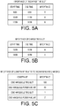
- FIG. 5A is a diagram illustrating importance of a discharge time slot in the parameters for constraint calculation.
- FIG. 5B is a diagram illustrating importance of a charge time slot in the parameters for constraint calculation.
- FIG. 5C is a diagram illustrating importance of a constraint related to discharging and charging in the parameters for constraint calculation.
- the parameters for constraint calculation to be transmitted from the power grid control system 20 to the hydrogen-energy integrated management system 50 include importance of a discharge time slot, importance of a charge time slot, importance of each constraint related to discharging and charging.
- importance of a discharge time slot is a constraint condition indicating a time slot during which discharging to the power grid 74 is possible by importance. For example, in a case of discharging at 10:00 to 11:59, importance is A, which indicates the corresponding time slot is most desirable. That is, power demand in the power grid 74 is highest at 10:00 to 11:59.
- the time slot with the second highest importance is a time slot 17:00 to 18:59 having importance B, and the following is a time slot 8:00 to 9:59 having importance C.
- importance of discharging becomes higher in a time slot in which power demand is high and power shortage occurs.
- importance of a charge time slot is a constraint condition indicating a time slot during which charging of the hydrogen energy system 10 is possible by importance.
- importance is A, which indicates the corresponding time slot is most desirable. That is, a time slot in which excessive supply occurs in the power grid 74 is a time slot 13:00 to 15:59.
- a time slot in which the second most excessive supply occurs is a time slot 16:00 to 16:59 having importance B.
- importance of charging becomes higher in a time slot in which power demand is low and supply is excessive.
- importance of a constraint related to discharging and charging is a constraint condition indicating each of a dischargeable time slot, a dischargeable power amount, a chargeable time slot, and a chargeable power amount by importance. It can be found that, for example, in a case where the importance of the dischargeable time slot is 100, the importance of the dischargeable power amount is 20, the importance of the chargeable time slot is 1, and the importance of the chargeable power amount is 2, the importance of the dischargeable time slot is highest, followed by the dischargeable power amount, the chargeable power amount, and the chargeable time slot.
- FIG. 6 is a diagram illustrating liquefied hydrogen demand and a processing concept of calculation of a target liquefied-hydrogen remaining amount.
- the concept of processing by the target hydrogen-amount acquisition portion 508a ( FIG. 3 ) is described with reference to FIG. 6 .
- the target hydrogen-amount acquisition portion 508a sets a target hydrogen remaining amount of the liquefied hydrogen tank 108 ( FIG. 1 ) at a predetermined time of each day, for example, 0:00 that is the beginning of one day, and a target hydrogen remaining amount at a shipping time based on demand for liquefied hydrogen received by the second communication portion 504 ( FIG. 3 ) from the renewable-energy control system 40, for example.
- the hydrogen demand includes information on a shipping date, a shipping time, and a shipping amount.
- the target hydrogen remaining amount is the shipping amount plus a margin amount.
- This margin amount can be set to any amount. That is, the target hydrogen-amount acquisition portion 508a divides the target liquefied-hydrogen remaining amount at the shipping time by the number of operable days of the hydrogen energy system 10 to acquire the target liquefied-hydrogen remaining amount of the liquefied hydrogen tank 108 ( FIG. 1 ) at the beginning of one day, for example, 0:00.
- the target hydrogen-amount acquisition portion 508a sets a target hydrogen remaining amount of the gaseous hydrogen tank 104 ( FIG. 1 ) at a predetermined time of each day, for example, 0:00 that is the beginning of one day, and a target hydrogen remaining amount at a shipping time based on demand for gaseous hydrogen received by the second communication portion 504 ( FIG. 3 ) from the renewable-energy control system 40, for example. That is, the target hydrogen-amount acquisition portion 508a divides the target gaseous-hydrogen remaining amount at the shipping time by the number of operable days of the hydrogen energy system 10 to acquire the target gaseous-hydrogen remaining amount of the gaseous hydrogen tank 104 at the beginning of one day, for example, 0:00.
- a method of setting the target liquefied-hydrogen remaining amount and the target gaseous-hydrogen remaining amount is not limited to the method of performing division by the number of operable days, and these amounts may be set by another method. Further, only one of the target liquefied-hydrogen remaining amount and the target gaseous-hydrogen remaining amount may be set.
- FIG. 7 is a diagram illustrating an example of a hydrogen-system constraint (discharging).
- the positive side of the vertical axis in FIG. 7 indicates discharge power of the hydrogen energy system 10, and the negative side indicates charge power.
- the horizontal axis indicates elapsed time during a discharge operation.
- FIG. 8 is a diagram illustrating numerical value examples of a constraint condition used in FIG. 7 .
- the "pre-discharge minimum keep time” includes a time to start driving the hydrogen power generator 114 ( FIG. 1 ), and is a time for which the stored amount of hydrogen in the gaseous hydrogen tank 104 ( FIG. 1 ) is taken into consideration, for example.
- the "dischargeable time slot” is a time slot based on importance of a discharge time slot in the parameters for constraint calculation.
- the "post-discharge minimum keep time” includes a time to stop driving the hydrogen power generator 114 ( FIG. 1 ), and is a time for which the stored amount of hydrogen in the gaseous hydrogen tank 104 ( FIG. 1 ) is taken into consideration, for example.
- the “dischargeable power amount” is an amount of power obtained by considering importance of a dischargeable power amount in the parameters for constraint calculation, the stored amount of hydrogen in the gaseous hydrogen tank 104 ( FIG. 1 ), and the like.
- an "upper limit of discharge-power change rate”, a “discharge minimum keep time”, and a “lower limit of discharge-power change rate” are constraints determined by static specifications of the discharging characteristics in the hydrogen energy system 10. More specifically, they are constraints determined by static specifications of the discharging characteristics in the hydrogen power generator 114 ( FIG. 1 ).
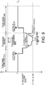
- FIG. 9 is a diagram illustrating an example of a hydrogen-system constraint (charging).
- the positive side of the vertical axis in FIG. 9 indicates discharge power of the hydrogen energy system 10, and the negative side indicates charge power.
- the horizontal axis indicates elapsed time during a 11 operation.
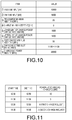
- FIG. 10 is a diagram illustrating numerical value examples of a constraint condition used in FIG. 9 .
- the "pre-charge minimum keep time” can be obtained based on, for example, the operating state of the hydrogen production device 102 ( FIG. 1 ) or the state of the remaining amount in the gaseous hydrogen tank 104.
- the "chargeable time slot” is a time slot based on importance of a charge time slot in the parameters for constraint calculation.
- the "post-charge minimum keep time” includes a time to stop driving the hydrogen production device 102 ( FIG. 1 ), and is a time for which the stored amount of hydrogen in the gaseous hydrogen tank 104 ( FIG. 1 ) is taken into consideration, for example.
- the "chargeable power amount” is an amount of power obtained by considering importance of a chargeable power amount in the parameters for constraint calculation, the stored amount of hydrogen in the gaseous hydrogen tank 104 ( FIG. 1 ), and the like.
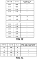
- FIG. 13 is a diagram illustrating an example of an answerback (OK/NG) based on an operation plan by the operation planning portion 508c ( FIG. 3 ).
- the operation planning portion 508c makes a time-series plan of charge and discharge power based on charge and discharge requests from the power grid control system 20 and forecast results of renewable-energy power generation of the renewable-energy control system 40.
- the hydrogen-energy integrated management system 50 then transmits a signal including information of OK as an answerback to the power grid control system 20 when it is possible to respond to a charge or discharge request from the power grid control system 20.
- the constraint-condition setting portion 508b of the hydrogen-energy integrated management system 50 calculates and sets a time-series hydrogen-system constraint of the hydrogen energy system 10 using the parameters for constraint calculation and the target hydrogen remaining amounts (a protocol P106). Subsequently, the constraint-condition setting portion 508b transmits the calculated hydrogen-system constraint to the power grid control system 20.
- the power grid control system 20 plans time-series charge and discharge requests using the hydrogen-system constraint and transmits them to the operation planning portion 508c of the hydrogen-energy integrated management system 50 (a protocol P108). Further, the renewable-energy control system 40 transmits forecast results of renewable-energy power generation to the operation planning portion 508c of the hydrogen-energy integrated management system 50 (a protocol P110).
- the operation planning portion 508c creates an operation plan of the hydrogen energy system 10 based on the time-series charge and discharge requests and the forecast results of renewable-energy power generation, and transmits an answerback to the power grid control system 20 (a protocol P112).
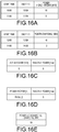
- FIG. 16A is a diagram illustrating an example of a real-time discharge request.
- FIG. 16B is a diagram illustrating an example of a real-time charge request.
- FIG. 16C is a diagram illustrating an example of a reactive power request of a real-time short-period power request.
- FIG. 16D is a diagram illustrating a different example of a reactive power request of a real-time short-period power request.
- FIG. 16E is a diagram illustrating an example of an LFC (load frequency control) request of a real-time short-period power request.
- the real-time short-period power request indicates a short-period power request for Td minutes after Td minutes, for example.
- the reactive power request may be a pair of active power and reactive power as illustrated in FIG. 16C or may be a pair of a power factor and reactive power as illustrated in FIG. 16D .
- FIG. 17 is a diagram illustrating a sequence example of real-time processing.
- a processing cycle is Ta minutes.
- Ta is any value. That is, each of the intervals between t0 and t1, t1 and t2, t2 and t3, and t3 and t4 is Ta minutes.
- Tb minutes a time obtained by adding an extra time to a time from a stop state to a power-generation possible state in order for the hydrogen power generator 114 to generate power
- Tc minutes a time obtained by adding an extra time to a time from a stop state to a production possible state in order for a hydrogen production device to perform charging.
- Tbc The smaller one of Tb and Tc is assumed as Tbc.
- the constraint-condition setting portion 508b of the hydrogen-energy integrated management system 50 calculates and sets a real-time hydrogen-system constraint using parameters for constraint calculation, a target hydrogen remaining amount, and a charge request and a discharge request after the present time (a protocol P200). Subsequently, the constraint-condition setting portion 508b transmits the calculated real-time hydrogen-system constraint to the power grid control system 20.
- the power grid control system 20 plans real-time charge and discharge requests using the real-time hydrogen-system constraint and transmits the real-time charge request and the real-time discharge request to the operation planning portion 508c of the hydrogen-energy integrated management system 50 (a protocol P202). Further, the renewable-energy control system 40 transmits a real-time forecast result of renewable-energy power generation to the operation planning portion 508c of the hydrogen-energy integrated management system 50 (a protocol P204).
- the operation planning portion 508c creates a real-time operation plan of the hydrogen energy system 10 based on the real-time charge and discharge requests and the real-time forecast result of renewable-energy power generation, and transmits an answerback to the power grid control system 20 (a protocol P206). In this manner, the operation planning portion 508c further creates an operation plan with a shorter period than the operation plan ( FIG. 14 ).
- the power grid control system 20 calculates short-period power demand and transmits it to the operation planning portion 508c of the hydrogen-energy integrated management system 50 (a protocol P210).
- the operation planning unit 508c checks a short-period power request from the power grid control system 20 (a protocol P212) and determines whether it is possible to respond to that request (a protocol P214).
- a protocol P214 determines whether it is possible to respond to that request (possible in the protocol P214)
- the power grid control system 20 executes control of responding to short-period power (a protocol P216). Meanwhile, when it is impossible to respond to that request (impossible in the protocol P214), the control is put on hold to wait until a predetermined time elapses.
- the target hydrogen-amount acquisition portion 508a of the hydrogen-energy integrated management system 50 is configured to acquire a target hydrogen-production amount based on hydrogen demand data of the hydrogen transport system 30, and the operation planning portion 508c of the hydrogen-energy integrated management system 50 creates an operation plan in the hydrogen energy system 10 based on the target hydrogen-production amount and data of a charge request of the power grid control system 20. Accordingly, it is possible to adjust independent request processes of the power grid control system 20 and the hydrogen transport system 30 by control based on the operation plan of the hydrogen energy system 10, also in a case where the power grid control system 20 and the hydrogen transport system 30 execute control independently of each other.
- a first modification of the embodiment is different from the embodiment in further including a display controller 512 that causes a monitor to display the operation state of the hydrogen energy system 10. Differences between the first modification and the embodiment are described below.
- the display controller 512 executes display control that causes a display, for example, a monitor to display the operation state of the hydrogen energy system 10.
- FIG. 20 is a diagram illustrating an example of a display screen of a charge or discharge state of the hydrogen energy system 10. As illustrated in FIG. 20 , the display controller 512 displays a screen on a monitor together with numerical values indicating the charge or discharge state of the hydrogen energy system 10.
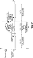
- FIG. 21 is a diagram illustrating an example of a display screen of a constraint of the hydrogen energy system 10.
- the display controller 512 displays a screen on a monitor together with numerical values indicating the constraint of the hydrogen energy system 10 during discharging.
- the display controller 512 can also change the numerical values by input processing of an operation portion.
- the display controller 512 can display an equivalent screen also during charging.
- a display screen of a charge or discharge state is caused to be displayed on a monitor, thereby making it easy to understand the state and to find a defect. Further, by displaying the display screen on the monitor together with numerical values indicating a constraint during discharging, it becomes easy to understand a constraint state during discharging, and it also becomes possible to reduce setting errors.
- a second modification of the embodiment is different from the embodiment in that the hydrogen energy system 10 further includes a storage battery 116 and a heat storage tank 118. Differences between the second modification and the embodiment are described below.
- FIG. 22 is a block diagram illustrating a detailed configuration of the hydrogen energy system 10 according to the second modification of the embodiment. As illustrated in FIG. 22 , the hydrogen energy system 10 is different from that in the embodiment in including the storage battery 116 and the heat storage tank 118.
- the storage battery 116 supplements power supply to the power grid 74 when power generated by the hydrogen power generator 114 is insufficient. Therefore, it is possible to perform power supply of the hydrogen power generator 114 more stably. Further, the storage battery 116 can effectively use renewable energy or the like, because it has a higher response speed than the hydrogen power generator 114.
- the heat storage tank 118 stores therein heat of the hydrogen power generator 114.
- the hydrogen energy system 10 includes the storage battery 116, and it is therefore possible to effectively use renewable energy or the like and to reduce power consumption in the entire hydrogen energy system 10. Further, since the hydrogen energy system 10 includes the heat storage tank 118, it is possible to supply heat discharged from the hydrogen power generator 114 in accordance with a time during which heat can be used.
Landscapes
- Engineering & Computer Science (AREA)
- Sustainable Energy (AREA)
- Life Sciences & Earth Sciences (AREA)
- Sustainable Development (AREA)
- Power Engineering (AREA)
- Electrochemistry (AREA)
- Chemical & Material Sciences (AREA)
- Chemical Kinetics & Catalysis (AREA)
- General Chemical & Material Sciences (AREA)
- Manufacturing & Machinery (AREA)
- General Engineering & Computer Science (AREA)
- Physics & Mathematics (AREA)
- General Physics & Mathematics (AREA)
- Automation & Control Theory (AREA)
- Supply And Distribution Of Alternating Current (AREA)
- Human Computer Interaction (AREA)
- Remote Monitoring And Control Of Power-Distribution Networks (AREA)
- Fuel Cell (AREA)
Abstract
Description
- Embodiments of the present invention relate to a hydrogen-energy control system and a control method for a hydrogen-energy control system.
- Hydrogen energy is attracting attention as new energy. Hydrogen is produced by a hydrogen production device of a hydrogen system and stored in a hydrogen tank. The hydrogen stored in the hydrogen tank can be reconverted into power by a hydrogen power generator. Therefore, by connecting the devices in a hydrogen system to a power grid, it is possible to both supply power from the power grid and supply power to the power grid. An example of the hydrogen power generator is a fuel cell. In this manner, it is possible to stabilize the power grid and respond to hydrogen demand by the hydrogen system.
- Further, in the future, demand for hydrogen itself is also expected to increase because of increase in fuel cell vehicles using hydrogen as fuel and increase in pure hydrogen fuel cells for home use. In this case, hydrogen is transported or sent by a pipeline. Therefore, efficient energy management of hydrogen and power is required.
- However, when management of the power grid, management of the hydrogen demand, and management of the hydrogen system are performed by one management control system, there is a possibility that processing becomes complicated.
- Patent Literature 1:
Japanese Patent Publication No. 3801898 - An object of the present invention is to provide a hydrogen-energy control system capable of adjusting independent request processes of a power grid control system and a hydrogen transport system in accordance with an operation plan of a hydrogen energy system.
- A hydrogen-energy control system according to the present embodiment comprises: a hydrogen energy system configured to produce at least hydrogen by power; a power grid control system configured to make a power generation plan of a power facility that supplies power to a power grid; a hydrogen transport system configured to manage hydrogen transport; and a hydrogen-energy integrated management system configured to control the hydrogen energy system based on the power grid control system and information on communication with the power grid control system, wherein the hydrogen-energy integrated management system includes a first communication portion configured to perform communication of at least data of a charge request in charge and discharge requests with the power grid control system, a second communication portion configured to perform communication of hydrogen demand data with the hydrogen transport system, a target hydrogen-amount acquisition portion configured to acquire a target hydrogen-production amount based on the hydrogen demand data, and an operation planning portion configured to create an operation plan in the hydrogen energy system based on the target hydrogen-production amount and the data of the charge request.
- According to the present embodiment, it is possible to adjust independent request processes of a power grid control system and a hydrogen transport system.
-
- [
FIG. 1] FIG. 1 is a block diagram illustrating a configuration of a hydrogen-energy control system. - [
FIG. 2] FIG. 2 is a conceptual diagram illustrating a configuration of a hydrogen energy system as a battery. - [
FIG. 3] FIG. 3 is a block diagram illustrating a detailed configuration of a hydrogen-energy integrated management system. - [
FIG. 4] FIG. 4 is a diagram illustrating communication information between systems. - [
FIG. 5A] FIG. 5A is a diagram illustrating importance of a discharge time slot in parameters for constraint calculation. - [
FIG. 5B] FIG. 5B is a diagram illustrating importance of a charge time slot in the parameters for constraint calculation. - [
FIG. 5C] FIG. 5C is a diagram illustrating importance of a constraint related to discharging and charging. - [
FIG. 6] FIG. 6 is a diagram illustrating liquefied hydrogen demand and a processing concept of calculation of a target liquefied-hydrogen remaining amount. - [
FIG. 7] FIG. 7 is a diagram illustrating an example of a hydrogen-system constraint (discharging). - [
FIG. 8] FIG. 8 is a diagram illustrating numerical value examples of a constraint condition used inFIG. 7 . - [
FIG. 9] FIG. 9 is a diagram illustrating an example of a hydrogen-system constraint (charging). - [
FIG. 10] FIG. 10 is a diagram illustrating numerical value examples of a constraint condition used inFIG. 9 . - [
FIG. 11] FIG. 11 is a diagram illustrating an example of charge and discharge requests from a power grid control system. - [
FIG. 12] FIG. 12 is a diagram illustrating an example of data of forecast results of renewable-energy power generation. - [
FIG. 13] FIG. 13 is a diagram illustrating an example of an answerback (OK/NG). - [
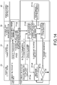
FIG. 14] FIG. 14 is a diagram illustrating a protocol of data and a flow of processing. - [
FIG. 15] FIG. 15 is a diagram illustrating an example of data transmitted and received between systems in real time. - [
FIG. 16A] FIG. 16A is a diagram illustrating an example of a real-time discharge request. - [
FIG. 16B] FIG. 16B is a diagram illustrating an example of a real-time charge request. - [
FIG. 16C] FIG. 16C is a diagram illustrating an example of a reactive power request of a real-time short-period power request. - [
FIG. 16D] FIG. 16D is a diagram illustrating a different example of a reactive power request. - [
FIG. 16E] FIG. 16E is a diagram illustrating an example of an LFC (load frequency control) request of a real-time short-period power request. - [
FIG. 17] FIG. 17 is a diagram illustrating a sequence example of real-time processing. - [
FIG. 18] FIG. 18 is a diagram illustrating a protocol of data transmitted and received between systems in real time and a flow of processing. - [
FIG. 19] FIG. 19 is a block diagram illustrating a detailed configuration of a hydrogen-energy integrated management system according to a first modification of an embodiment. - [
FIG. 20] FIG. 20 is a diagram illustrating an example of a display screen of a charge or discharge state of a hydrogen energy system. - [
FIG. 21] FIG. 21 is a diagram illustrating an example of a display screen of a constraint of the hydrogen energy system. - [
FIG. 22] FIG. 22 is a block diagram illustrating a detailed configuration of a hydrogen energy system according to a second modification of the embodiment. - A hydrogen-energy control system and a control method for a hydrogen-energy control system according to embodiments of the present invention will now be explained in detail with reference to the accompanying drawings. The embodiments described below are only examples of the embodiments of the present invention and it is not to be understood that the present invention is limited to these embodiments. In the drawings referred to in the embodiments, same parts or parts having identical functions are denoted by like or similar reference characters and there is a case where redundant explanations thereof are omitted. Further, for convenience of explanation, there are cases where dimensional ratios of the parts in the drawings are different from those of actual products and some part of configurations is omitted from the drawings.
-
FIG. 1 is a block diagram illustrating a configuration of a hydrogen-energy control system 1 according to an embodiment. As illustrated inFIG. 1 , thehydrogen energy system 1 according to the present embodiment is configured to include ahydrogen energy system 10, a powergrid control system 20, ahydrogen transport system 30, a renewable-energy control system 40, a hydrogen-energy integratedmanagement system 50, a renewable-energy-derivedpower facility 60. Further, a fossil-fuel-derivedpower facility 70, ahydrogen distribution network 80, and ahot water network 90 are illustrated inFIG. 1 . - The
hydrogen energy system 10 produces at least hydrogen by power. A detailed configuration of thehydrogen energy system 10 will be described later. - The power
grid control system 20 makes a power generation plan of a power facility that supplies power to apower grid 74, for example, athermal power plant 72. The powergrid control system 20 performs communication of at least data of a charge request in charge and discharge requests with the hydrogen-energy integratedmanagement system 50. - The
hydrogen transport system 30 manages hydrogen transport. Thehydrogen transport system 30 performs communication of hydrogen demand data with the hydrogen-energy integratedmanagement system 50. - The renewable-
energy control system 40 controls the renewable-energy-derivedpower facility 60. The renewable-energy control system 40 performs communication of data of a forecast result of renewable-energy power generation with the hydrogen-energy integratedmanagement system 50. - The hydrogen-energy integrated
management system 50 controls thehydrogen energy system 10 based on information on communication with the powergrid control system 20, thehydrogen transport system 30, and the renewable-energy control system 40. A detailed configuration of the hydrogen-energy integratedmanagement system 50 will be described later. - The renewable-energy-derived
power facility 60 includes a natural energy-derived power facility. This renewable-energy-derivedpower facility 60 includes aphotovoltaic power generator 62 using sunlight and awind power generator 64 that generates power using wind. This renewable-energy-derivedpower facility 60 does not require fuel such as fossil fuel, but the amount of power generated is unstable because of environmental influences such as the weather and wind power. The renewable-energy-derivedpower facility 60 may be a power facility that uses new energy such as biomass or biomass-derived waste. - The fossil-fuel-derived
power facility 70 includes thethermal power plant 72 and thepower grid 74. Thethermal power plant 72 generates power using fossil fuel. Thepower grid 74 is a power grid to which the renewable-energy-derivedpower facility 60, the fossil-fuel-derivedpower facility 70, and ahydrogen power generator 114 are connected and to which power generated by the renewable-energy-derivedpower facility 60, the fossil-fuel-derivedpower facility 70, and thehydrogen power generator 114 is supplied. - The
hydrogen distribution network 80 includes a liquefied-hydrogen distribution network 82 and a gaseous-hydrogen distribution network 84. The liquefied-hydrogen distribution network 82 is a distribution network that transports hydrogen as a liquid and supplies it to hydrogen demand. The gaseous-hydrogen distribution network 84 is a distribution network that transports hydrogen as a gas and supplies it to hydrogen demand. - Here, a detailed configuration of the
hydrogen energy system 10 is described. Thehydrogen energy system 10 is configured to include apower conditioner device 100, ahydrogen production device 102, agaseous hydrogen tank 104, aliquefier 106, a liquefiedhydrogen tank 108, a liquefied-hydrogen discharge device 110, avaporizer 112, and thehydrogen power generator 114. - The
power conditioner device 100 is configured to include a converter, for example. The converter converts direct-current power output from the renewable-energy-derivedpower facility 60 into predetermined alternating-current power. - The
hydrogen production device 102 produces hydrogen from electricity and water by water electrolysis. That is, thehydrogen production device 102 produces hydrogen by electrolysis of water using power supplied from at least either one of the renewable-energy-derivedpower facility 60 or thepower grid 74, and stores the produced hydrogen in thegaseous hydrogen tank 104. Thehydrogen production device 102 is, for example, a water electrolysis device that produces hydrogen and oxygen by causing an electric current to pass through an alkaline solution. Further, thehydrogen production device 102 stores the produced hydrogen in thegaseous hydrogen tank 104 via a hydrogen pipe. - The
gaseous hydrogen tank 104 stores therein the gaseous hydrogen produced by thehydrogen production device 102. Thegaseous hydrogen tank 104 is connected to thehydrogen production device 102, theliquefier 106, and the gaseous-hydrogen distribution network 6. Thegaseous hydrogen tank 104 also supplies the gaseous hydrogen to theliquefier 106 and the gaseous-hydrogen distribution network 84. - The
liquefier 106 converts the gaseous hydrogen supplied from thegaseous hydrogen tank 104 into liquefied hydrogen. Theliquefier 106 converts the hydrogen supplied from thegaseous hydrogen tank 104 into liquefied hydrogen and supplies the liquefied hydrogen to the liquefiedhydrogen tank 108 via a pipe. - The liquefied
hydrogen tank 108 stores therein the liquefied hydrogen supplied from theliquefier 106. The liquefiedhydrogen tank 108 stores therein the liquefied hydrogen supplied from theliquefier 106 and also supplies the liquefied hydrogen to the liquefied-hydrogen discharge device 110 via a pipe. - The liquefied-
hydrogen discharge device 110 supplies the liquefied hydrogen supplied from the liquefiedhydrogen tank 108 to the liquefied-hydrogen distribution network 82 and thevaporizer 112. The liquefied-hydrogen discharge device 110 may be configured to be integrated with the liquefiedhydrogen tank 108. - The
vaporizer 112 converts the liquefied hydrogen supplied from the liquefied-hydrogen discharge device 110 into gaseous hydrogen. That is, thevaporizer 112 converts the liquefied hydrogen supplied from the liquefied-hydrogen discharge device 110 into gaseous hydrogen and supplies the gaseous hydrogen to thegaseous hydrogen tank 104 via a pipe. - The
hydrogen power generator 114 generates power and heat using the hydrogen supplied from thegaseous hydrogen tank 104. The heat generated here is supplied to thehot water network 90 as hot water, for example. Thehydrogen power generator 114 includes, for example, a fuel cell. That is, thehydrogen power generator 114 generates electricity using the hydrogen supplied from thegaseous hydrogen tank 104 and also generates heat. As for oxygen, thehydrogen power generator 114 may use oxygen in the air or oxygen that is produced in association with production of hydrogen by thehydrogen production device 102 and is stored in an oxygen tank. -
FIG. 2 is a conceptual diagram illustrating a configuration of thehydrogen energy system 10 as a battery. As illustrated inFIG. 2 , thehydrogen energy system 10 performs charging by producing hydrogen using power supplied from the renewable-energy-derivedpower facility 60 and the fossil-fuel-derivedpower facility 70. That is, charging of thehydrogen energy system 10 according to the present embodiment means converting power into gaseous hydrogen. A chargeable power amount depends on the free capacity of thegaseous hydrogen tank 104. - Meanwhile, a dischargeable power amount depends on the storage capacities of the
gaseous hydrogen tank 104 and the liquefiedhydrogen tank 108. In this case, the dischargeable power amount is affected by demand for gaseous hydrogen and demand for liquefied hydrogen. The dischargeable power amount of thehydrogen energy system 10 is also affected by the amount of supply of hot water to thehot water network 90. In addition, discharging of thehydrogen energy system 10 according to the present embodiment means converting hydrogen in thegaseous hydrogen tank 104 into power. - As described above, in charging and discharging of the
hydrogen energy system 10, it is necessary to consider not only power but also the amount of heat and the amount of hydrogen. Therefore, it is not always possible to respond to a request for power supply and demand. Accordingly, thehydrogen energy system 10 has constraints such as a chargeable time slot, a dischargeable time slot, a chargeable power amount, and a dischargeable power amount. -
FIG. 3 is a block diagram illustrating a detailed configuration of the hydrogen-energy integratedmanagement system 50. As illustrated inFIG. 3 , the hydrogen-energy integratedmanagement system 50 includes afirst communication portion 502, asecond communication portion 504, athird communication portion 506, amanagement portion 508, and astorage 510. - The
first communication portion 502 is a first interface between the powergrid control system 20 and the hydrogen-energy integratedmanagement system 50. - The
second communication portion 504 is a second interface between thehydrogen transport system 30 and the hydrogen-energy integratedmanagement system 50. - The
third communication portion 506 is a third interface between the renewable-energy control system 40 and the hydrogen-energy integratedmanagement system 50. Detailed communication contents of thefirst communication portion 502, thesecond communication portion 504, and thethird communication portion 506 will be described later. - The
management portion 508 is configured to include a CPU (Central Processing Unit), for example, and manages thehydrogen energy system 10, the powergrid control system 20, thehydrogen transport system 30, and the renewable-energy control system 40. Themanagement portion 508 includes a target hydrogen-amount acquisition portion 508a, a constraint-condition setting portion 508b, and anoperation planning portion 508c. - The target hydrogen-
amount acquisition portion 508a acquires a target hydrogen-production amount based on hydrogen demand data transmitted from thehydrogen transport system 30. - The constraint-
condition setting portion 508b calculates a time-series hydrogen-system constraint condition for producing the target hydrogen-production amount based on at least the hydrogen-production characteristics or the hydrogen power-generation characteristics of thehydrogen energy system 10. - The
operation planning portion 508c creates an operation plan in thehydrogen energy system 10 based on the target hydrogen-production amount acquired by the target hydrogen-amount acquisition portion 508a and data of a charge request transmitted from the powergrid control system 20. The details of the target hydrogen-amount acquisition portion 508a, the constraint-condition setting portion 508b, and theoperation planning portion 508c will be also described later. - The
storage 510 is implemented by a semiconductor memory element such as a RAM (Random Access Memory) or a flash memory, a hard disk, or the like. Thestorage 510 stores therein a program to be executed by themanagement portion 508 and various control data. - Detailed communication information of the
first communication portion 502, thesecond communication portion 504, and thethird communication portion 506 during normal control is described with reference toFIG. 4 . -
FIG. 4 is a diagram illustrating communication information between the powergrid control system 20, thehydrogen transport system 30, the renewable-energy control system 40, and the hydrogen-energy integratedmanagement system 50. These pieces of communication information are information transmitted and received between the systems in advance. - As illustrated in
FIG. 4 , the first communication portion 502 (FIG. 3 ) performs communication of at least data of a charge request in charge and discharge requests with the powergrid control system 20. More specifically, thefirst communication portion 502 receives parameters for constraint calculation and charge and discharge requests from the powergrid control system 20. - Meanwhile, the
first communication portion 502 transmits a hydrogen-system constraint and an answerback (OK/NG) from the hydrogen-energy integratedmanagement system 50 to the powergrid control system 20. The parameters for constraint calculation, the charge and discharge requests, the hydrogen-system constraint, and the answerback (OK/NG) are communicated at a predetermined cycle, for example, once a day. - The second communication portion 504 (
FIG. 3 ) performs communication of hydrogen demand data with thehydrogen transport system 30. The hydrogen demand data is communicated at a predetermined cycle, for example, once a week. - The third communication portion 506 (
FIG. 3 ) performs communication of forecast result data of renewable-energy power generation with the renewable-energy control system 40. The forecast result data of renewable-energy power generation is communicated at a predetermined cycle, for example, once a day. Communication information of thefirst communication portion 502, thesecond communication portion 504, and thethird communication portion 506 during real-time control will be described later. - Here, details of the above-described parameters for constraint calculation are described with reference to
FIGS. 5A to 5C. FIG. 5A is a diagram illustrating importance of a discharge time slot in the parameters for constraint calculation.FIG. 5B is a diagram illustrating importance of a charge time slot in the parameters for constraint calculation.FIG. 5C is a diagram illustrating importance of a constraint related to discharging and charging in the parameters for constraint calculation. As illustrated inFIGS. 5A to 5C , the parameters for constraint calculation to be transmitted from the powergrid control system 20 to the hydrogen-energy integratedmanagement system 50 include importance of a discharge time slot, importance of a charge time slot, importance of each constraint related to discharging and charging. - As illustrated in
FIG. 5A , importance of a discharge time slot is a constraint condition indicating a time slot during which discharging to thepower grid 74 is possible by importance. For example, in a case of discharging at 10:00 to 11:59, importance is A, which indicates the corresponding time slot is most desirable. That is, power demand in thepower grid 74 is highest at 10:00 to 11:59. The time slot with the second highest importance is a time slot 17:00 to 18:59 having importance B, and the following is a time slot 8:00 to 9:59 having importance C. As can be found from the above description, importance of discharging becomes higher in a time slot in which power demand is high and power shortage occurs. - As illustrated in
FIG. 5B , importance of a charge time slot is a constraint condition indicating a time slot during which charging of thehydrogen energy system 10 is possible by importance. For example, in a case of charging at 13:00 to 15:59, importance is A, which indicates the corresponding time slot is most desirable. That is, a time slot in which excessive supply occurs in thepower grid 74 is a time slot 13:00 to 15:59. A time slot in which the second most excessive supply occurs is a time slot 16:00 to 16:59 having importance B. As can be found from the above description, importance of charging becomes higher in a time slot in which power demand is low and supply is excessive. - As illustrated in
FIG. 5C , importance of a constraint related to discharging and charging is a constraint condition indicating each of a dischargeable time slot, a dischargeable power amount, a chargeable time slot, and a chargeable power amount by importance. It can be found that, for example, in a case where the importance of the dischargeable time slot is 100, the importance of the dischargeable power amount is 20, the importance of the chargeable time slot is 1, and the importance of the chargeable power amount is 2, the importance of the dischargeable time slot is highest, followed by the dischargeable power amount, the chargeable power amount, and the chargeable time slot. -
FIG. 6 is a diagram illustrating liquefied hydrogen demand and a processing concept of calculation of a target liquefied-hydrogen remaining amount. The concept of processing by the target hydrogen-amount acquisition portion 508a (FIG. 3 ) is described with reference toFIG. 6 . As illustrated inFIG. 6 , the target hydrogen-amount acquisition portion 508a sets a target hydrogen remaining amount of the liquefied hydrogen tank 108 (FIG. 1 ) at a predetermined time of each day, for example, 0:00 that is the beginning of one day, and a target hydrogen remaining amount at a shipping time based on demand for liquefied hydrogen received by the second communication portion 504 (FIG. 3 ) from the renewable-energy control system 40, for example. Here, the hydrogen demand includes information on a shipping date, a shipping time, and a shipping amount. The target hydrogen remaining amount is the shipping amount plus a margin amount. This margin amount can be set to any amount. That is, the target hydrogen-amount acquisition portion 508a divides the target liquefied-hydrogen remaining amount at the shipping time by the number of operable days of thehydrogen energy system 10 to acquire the target liquefied-hydrogen remaining amount of the liquefied hydrogen tank 108 (FIG. 1 ) at the beginning of one day, for example, 0:00. - Similarly, the target hydrogen-
amount acquisition portion 508a sets a target hydrogen remaining amount of the gaseous hydrogen tank 104 (FIG. 1 ) at a predetermined time of each day, for example, 0:00 that is the beginning of one day, and a target hydrogen remaining amount at a shipping time based on demand for gaseous hydrogen received by the second communication portion 504 (FIG. 3 ) from the renewable-energy control system 40, for example. That is, the target hydrogen-amount acquisition portion 508a divides the target gaseous-hydrogen remaining amount at the shipping time by the number of operable days of thehydrogen energy system 10 to acquire the target gaseous-hydrogen remaining amount of thegaseous hydrogen tank 104 at the beginning of one day, for example, 0:00. A method of setting the target liquefied-hydrogen remaining amount and the target gaseous-hydrogen remaining amount is not limited to the method of performing division by the number of operable days, and these amounts may be set by another method. Further, only one of the target liquefied-hydrogen remaining amount and the target gaseous-hydrogen remaining amount may be set. - First, a hydrogen-system constraint of the
hydrogen energy system 10 during discharging in the constraint-condition setting portion 508b (FIG. 3 ) is described with reference toFIGS. 7 and8 .FIG. 7 is a diagram illustrating an example of a hydrogen-system constraint (discharging). The positive side of the vertical axis inFIG. 7 indicates discharge power of thehydrogen energy system 10, and the negative side indicates charge power. The horizontal axis indicates elapsed time during a discharge operation.FIG. 8 is a diagram illustrating numerical value examples of a constraint condition used inFIG. 7 . - As illustrated in
FIG. 7 , the constraint-condition setting portion 508b sets, as a constraint condition, dischargeable power with respect to the elapsed time using a target liquefied-hydrogen remaining amount and a target gaseous-hydrogen remaining amount acquired by the target hydrogen-amount acquisition portion 508a and parameters for constraint calculation supplied from the powergrid control system 20. A "pre-discharge minimum keep time", a "dischargeable time slot", a "post-discharge minimum keep time", and a "dischargeable power amount", which are underlined, are constraints that are dynamically varied by hydrogen demand or the like. - That is, the "pre-discharge minimum keep time" includes a time to start driving the hydrogen power generator 114 (
FIG. 1 ), and is a time for which the stored amount of hydrogen in the gaseous hydrogen tank 104 (FIG. 1 ) is taken into consideration, for example. The "dischargeable time slot" is a time slot based on importance of a discharge time slot in the parameters for constraint calculation. The "post-discharge minimum keep time" includes a time to stop driving the hydrogen power generator 114 (FIG. 1 ), and is a time for which the stored amount of hydrogen in the gaseous hydrogen tank 104 (FIG. 1 ) is taken into consideration, for example. The "dischargeable power amount" is an amount of power obtained by considering importance of a dischargeable power amount in the parameters for constraint calculation, the stored amount of hydrogen in the gaseous hydrogen tank 104 (FIG. 1 ), and the like. - Meanwhile, an "upper limit of discharge-power change rate", a "discharge minimum keep time", and a "lower limit of discharge-power change rate" are constraints determined by static specifications of the discharging characteristics in the
hydrogen energy system 10. More specifically, they are constraints determined by static specifications of the discharging characteristics in the hydrogen power generator 114 (FIG. 1 ). - Next, a hydrogen-system constraint of the
hydrogen energy system 10 during charging in the constraint-condition setting portion 508b (FIG. 3 ) is described with reference toFIGS. 9 and10 .FIG. 9 is a diagram illustrating an example of a hydrogen-system constraint (charging). The positive side of the vertical axis inFIG. 9 indicates discharge power of thehydrogen energy system 10, and the negative side indicates charge power. The horizontal axis indicates elapsed time during a 11 operation.FIG. 10 is a diagram illustrating numerical value examples of a constraint condition used inFIG. 9 . - As illustrated in
FIG. 9 , the constraint-condition setting portion 508b sets, as a constraint condition, chargeable power with respect to the elapsed time using a target liquefied-hydrogen remaining amount and a target gaseous-hydrogen remaining amount acquired by the target hydrogen-amount acquisition portion 508a and parameters for constraint calculation supplied from the powergrid control system 20. A "pre-charge minimum keep time", a "chargeable time slot", a "post-charge minimum keep time", and a "chargeable power amount", which are underlined, are constraints that are dynamically varied by hydrogen demand or the like. - That is, the "pre-charge minimum keep time" can be obtained based on, for example, the operating state of the hydrogen production device 102 (
FIG. 1 ) or the state of the remaining amount in thegaseous hydrogen tank 104. The "chargeable time slot" is a time slot based on importance of a charge time slot in the parameters for constraint calculation. The "post-charge minimum keep time" includes a time to stop driving the hydrogen production device 102 (FIG. 1 ), and is a time for which the stored amount of hydrogen in the gaseous hydrogen tank 104 (FIG. 1 ) is taken into consideration, for example. The "chargeable power amount" is an amount of power obtained by considering importance of a chargeable power amount in the parameters for constraint calculation, the stored amount of hydrogen in the gaseous hydrogen tank 104 (FIG. 1 ), and the like. - Meanwhile, a "lower limit of charging change rate", a "discharge minimum keep time", and an "upper limit of charging change rate" are constraints determined by static specifications of the charging characteristics in the
hydrogen energy system 10. More specifically, the "lower limit of charging change rate", the "discharge minimum keep time", and the "upper limit of charging change rate" are constraints determined by static specifications of the charging characteristics in the hydrogen production device 102 (FIG. 1 ). -
FIG. 11 is a diagram illustrating an example of charge and discharge requests from the powergrid control system 20. As illustrated inFIG. 11 , the powergrid control system 20 plans times-series charge and discharge requests based on the hydrogen-system constraint set by the constraint-condition setting portion 508b. The charge and discharge requests include a plurality of discharge requests that are different from each other in a time slot and a discharge amount and a plurality of charge requests that are different from each other in a time slot and a charge amount. That is, the powergrid control system 20 can have a plurality of discharge requests and a plurality of charge requests. For example, the powergrid control system 20 requests any of the charge requests to the hydrogen-energy integratedmanagement system 50 via thesecond communication portion 504 in advance, with regard to a charge time slot in which power supply of thepower grid 74 exceeds demand. Accordingly, it is possible to supply power to thehydrogen energy system 10 in accordance with the supply state of thepower grid 74. Although the unit is MW in this example, it may be MWh. The charge and discharge requests may be demand responses. -
FIG. 12 is a diagram illustrating an example of data of forecast results of renewable-energy power generation in the renewable-energy control system 40. As illustrated inFIG. 12 , the renewable-energy control system 40 transmits time-series data of forecast results of renewable-energy power generation to the hydrogen-energy integratedmanagement system 50. -
FIG. 13 is a diagram illustrating an example of an answerback (OK/NG) based on an operation plan by theoperation planning portion 508c (FIG. 3 ). As illustrated inFIG. 13 , theoperation planning portion 508c makes a time-series plan of charge and discharge power based on charge and discharge requests from the powergrid control system 20 and forecast results of renewable-energy power generation of the renewable-energy control system 40. The hydrogen-energy integratedmanagement system 50 then transmits a signal including information of OK as an answerback to the powergrid control system 20 when it is possible to respond to a charge or discharge request from the powergrid control system 20. Meanwhile, the hydrogen-energy integratedmanagement system 50 transmits a signal including NG as an answerback and information on the amount of power shortage to the powergrid control system 20 when it is impossible to respond to the charge or discharge request from the powergrid control system 20. Theoperation planning unit 508c may make an operation plan for the next day on the previous day, or may make a long-term operation plan, for example, an operation plan for several weeks, several months, or several years if long-term data is available with regard to hydrogen demand and a forecast of renewable-energy power generation. -
FIG. 14 is a diagram illustrating a protocol of data transmitted and received between systems in advance and a flow of processing. As illustrated inFIG. 14 , thehydrogen transport system 30 transmits the amount of demand for gaseous hydrogen, the amount of demand for liquefied hydrogen, and a shipping date and time to the hydrogen-energy integratedmanagement system 50 via the second communication portion 504 (a protocol P100). - Next, the target hydrogen-
amount acquisition portion 508a of the hydrogen-energy integratedmanagement system 50 sets a target hydrogen remaining amount of the liquefiedhydrogen tank 108 at a predetermined time of each day and a target hydrogen remaining amount at a shipping time based on the amount of demand for gaseous hydrogen and the amount of demand for liquefied hydrogen (a protocol P102). Further, the powergrid control system 20 calculates parameters for constraint calculation and transmits them to the hydrogen-energy integrated management system 50 (a protocol P104). - Next, the constraint-
condition setting portion 508b of the hydrogen-energy integratedmanagement system 50 calculates and sets a time-series hydrogen-system constraint of thehydrogen energy system 10 using the parameters for constraint calculation and the target hydrogen remaining amounts (a protocol P106). Subsequently, the constraint-condition setting portion 508b transmits the calculated hydrogen-system constraint to the powergrid control system 20. - Next, the power
grid control system 20 plans time-series charge and discharge requests using the hydrogen-system constraint and transmits them to theoperation planning portion 508c of the hydrogen-energy integrated management system 50 (a protocol P108). Further, the renewable-energy control system 40 transmits forecast results of renewable-energy power generation to theoperation planning portion 508c of the hydrogen-energy integrated management system 50 (a protocol P110). - Next, the
operation planning portion 508c creates an operation plan of thehydrogen energy system 10 based on the time-series charge and discharge requests and the forecast results of renewable-energy power generation, and transmits an answerback to the power grid control system 20 (a protocol P112). - Next, the power
grid control system 20 determines whether the answerback is OK at all times (a protocol P114). If all the answerbacks are OK (OK in the protocol P114), control is executed in accordance with the operation plan made in the protocol P108. On the other hand, when an answerback NG is included (NG in the protocol P114), the processing from the protocol P108 including change of the operation plan is repeated. Theoperation planning portion 508c may hold the answerback until a predetermined time elapses when creation of the operation plan fails, and may perform the answerback after an answer condition is satisfied. The reason is as follows. Before the predetermined time elapses, the forecast result of renewable-energy power generation may be changed and all of the operation plans may become OK. In this case, there is a possibility that processing efficiency as a whole increases when theoperation planning portion 508c waits for the predetermined time rather than when it repeats the processing from the protocol P202 including the change of the operation plan. - Next, data transmitted and received between systems in real time is described with reference to
FIG. 15. FIG. 15 is a diagram illustrating an example of data transmitted and received between systems in real time. As illustrated inFIG. 15 , the first communication portion 502 (FIG. 3 ) receives a real-time discharge request, a real-time charge request, and a real-time short-period power request from the powergrid control system 20. Here, a relation of a period Ta>a period Td is established, and the period Ta is on the order of several minutes, for example. The real-time discharge request and the real-time charge request are request signals with the period Ta, and the real-time short-period power request is a request signal with the period Td. -
FIG. 16A is a diagram illustrating an example of a real-time discharge request.FIG. 16B is a diagram illustrating an example of a real-time charge request. - Further, the first communication portion 502 (
FIG. 3 ) transmits a real-time hydrogen-system constraint and a real-time answerback (OK/NG) from the hydrogen-energy integratedmanagement system 50 to the powergrid control system 20. The real-time hydrogen-system constraint and the real-time answerback (OK/NG) are transmission signals with the period Ta. -
FIG. 16C is a diagram illustrating an example of a reactive power request of a real-time short-period power request.FIG. 16D is a diagram illustrating a different example of a reactive power request of a real-time short-period power request.FIG. 16E is a diagram illustrating an example of an LFC (load frequency control) request of a real-time short-period power request. As illustrated inFIGS. 16C to 16E , the real-time short-period power request indicates a short-period power request for Td minutes after Td minutes, for example. The reactive power request may be a pair of active power and reactive power as illustrated inFIG. 16C or may be a pair of a power factor and reactive power as illustrated inFIG. 16D . - As described above, the real-time short-period power request is a reactive power request for stabilizing a voltage of a system or an LFC that is a short-period request for stabilizing the frequency, for example. With regard to these requests, there is a possibility that calculation of a constraint or an operation plan is not completed in time. Therefore, only check is performed for these requests whether it is possible to respond to a request. If it is impossible to respond to the request, the request is not processed. Therefore, in the period Td, the real-time hydrogen-system constraint and the real-time answerback (OK/NG) are not transmitted to the power
grid control system 20 in some cases. - As illustrated in
FIG. 15 , the third communication portion 506 (FIG. 3 ) receives a real-time forecast result of renewable-energy power generation from the renewable-energy control system 40. The real-time forecast result of renewable-energy power generation is received by communication with the period Ta. -
FIG. 17 is a diagram illustrating a sequence example of real-time processing. Here, it is assumed that a processing cycle is Ta minutes. Ta is any value. That is, each of the intervals between t0 and t1, t1 and t2, t2 and t3, and t3 and t4 is Ta minutes. Further, it is assumed that a time obtained by adding an extra time to a time from a stop state to a power-generation possible state in order for thehydrogen power generator 114 to generate power is Tb minutes. Furthermore, it is assumed that a time obtained by adding an extra time to a time from a stop state to a production possible state in order for a hydrogen production device to perform charging is Tc minutes. The smaller one of Tb and Tc is assumed as Tbc. - A real-time hydrogen system constraint represents a constraint after Tbc minutes or later. For example, a real-time hydrogen-system constraint transmitted to the power
grid control system 20 at time t0 is set as a constraint at time t0+Tbc minutes or later. When calculating a real-time constraint, the constraint-condition setting portion 508b (FIG. 3 ) calculates and sets a real-time hydrogen-system constraint using an actual hydrogen-production result, a renewable-energy power generation result, a discharge request after the present time, and a charge request after the present time. For example, a real-time discharge request before Tb minutes is used as the discharge request after the present time, and a real-time charge request before Tc minutes is used for the charge request after the present time. Meanwhile, as the real-time discharge request, a request after Tb minutes is performed. As the real-time charge request, a request after Tc minutes is performed. The real-time forecast result of renewable-energy power generation is identical to a forecast result of renewable-energy power generation, but is a forecast result after the present time. -
FIG. 18 is a diagram illustrating a protocol of data transmitted and received between systems in real time and a flow of processing. Here, a protocol of real-time processing in a case of the period Ta is described first, and then a protocol of real-time processing in a case of the period Td is described. - In the case of the period Ta, first, the constraint-
condition setting portion 508b of the hydrogen-energy integratedmanagement system 50 calculates and sets a real-time hydrogen-system constraint using parameters for constraint calculation, a target hydrogen remaining amount, and a charge request and a discharge request after the present time (a protocol P200). Subsequently, the constraint-condition setting portion 508b transmits the calculated real-time hydrogen-system constraint to the powergrid control system 20. - Next, the power
grid control system 20 plans real-time charge and discharge requests using the real-time hydrogen-system constraint and transmits the real-time charge request and the real-time discharge request to theoperation planning portion 508c of the hydrogen-energy integrated management system 50 (a protocol P202). Further, the renewable-energy control system 40 transmits a real-time forecast result of renewable-energy power generation to theoperation planning portion 508c of the hydrogen-energy integrated management system 50 (a protocol P204). - Next, the
operation planning portion 508c creates a real-time operation plan of thehydrogen energy system 10 based on the real-time charge and discharge requests and the real-time forecast result of renewable-energy power generation, and transmits an answerback to the power grid control system 20 (a protocol P206). In this manner, theoperation planning portion 508c further creates an operation plan with a shorter period than the operation plan (FIG. 14 ). - Next, the power
grid control system 20 determines whether the answerback is OK at all times (a protocol P208). If all the answerbacks are OK (OK in the protocol P208), real-time control is executed in accordance with the power generation plan made in the protocol P202. On the other hand, when an answerback NG is included (NG in the protocol P208), the processing from the protocol P202 including change of the operation plan is repeated. Theoperation planning portion 508c may hold the answerback until a predetermined time elapses when creation of the operation plan fails, and may perform the answerback after an answer condition is satisfied. The reason is as follows. Before the predetermined time elapses, the real-time forecast result of renewable-energy power generation may be changed and all of the operation plans may become OK. In this case, there is a possibility that processing efficiency as a whole increases when theoperation planning portion 508c waits for the predetermined time rather than when it repeats the processing from the protocol P202 including the change of the operation plan. - In the case of the period Td, the power
grid control system 20 calculates short-period power demand and transmits it to theoperation planning portion 508c of the hydrogen-energy integrated management system 50 (a protocol P210). Theoperation planning unit 508c checks a short-period power request from the power grid control system 20 (a protocol P212) and determines whether it is possible to respond to that request (a protocol P214). When it is possible to respond to that request (possible in the protocol P214), the powergrid control system 20 executes control of responding to short-period power (a protocol P216). Meanwhile, when it is impossible to respond to that request (impossible in the protocol P214), the control is put on hold to wait until a predetermined time elapses. - As described above, according to the present embodiment, the target hydrogen-
amount acquisition portion 508a of the hydrogen-energy integratedmanagement system 50 is configured to acquire a target hydrogen-production amount based on hydrogen demand data of thehydrogen transport system 30, and theoperation planning portion 508c of the hydrogen-energy integratedmanagement system 50 creates an operation plan in thehydrogen energy system 10 based on the target hydrogen-production amount and data of a charge request of the powergrid control system 20. Accordingly, it is possible to adjust independent request processes of the powergrid control system 20 and thehydrogen transport system 30 by control based on the operation plan of thehydrogen energy system 10, also in a case where the powergrid control system 20 and thehydrogen transport system 30 execute control independently of each other. - A first modification of the embodiment is different from the embodiment in further including a
display controller 512 that causes a monitor to display the operation state of thehydrogen energy system 10. Differences between the first modification and the embodiment are described below. -
FIG. 19 is a block diagram illustrating a detailed configuration of the hydrogen-energy integratedmanagement system 50 according to the first modification of the embodiment. As illustrated inFIG. 19 , the hydrogen-energy integratedmanagement system 50 is different from that in the embodiment in including thedisplay controller 512. - The
display controller 512 executes display control that causes a display, for example, a monitor to display the operation state of thehydrogen energy system 10. -
FIG. 20 is a diagram illustrating an example of a display screen of a charge or discharge state of thehydrogen energy system 10. As illustrated inFIG. 20 , thedisplay controller 512 displays a screen on a monitor together with numerical values indicating the charge or discharge state of thehydrogen energy system 10. -
FIG. 21 is a diagram illustrating an example of a display screen of a constraint of thehydrogen energy system 10. As illustrated inFIG. 21 , thedisplay controller 512 displays a screen on a monitor together with numerical values indicating the constraint of thehydrogen energy system 10 during discharging. In this case, thedisplay controller 512 can also change the numerical values by input processing of an operation portion. Thedisplay controller 512 can display an equivalent screen also during charging. - As described above, according to the first modification of the embodiment, a display screen of a charge or discharge state is caused to be displayed on a monitor, thereby making it easy to understand the state and to find a defect. Further, by displaying the display screen on the monitor together with numerical values indicating a constraint during discharging, it becomes easy to understand a constraint state during discharging, and it also becomes possible to reduce setting errors.
- A second modification of the embodiment is different from the embodiment in that the
hydrogen energy system 10 further includes a storage battery 116 and aheat storage tank 118. Differences between the second modification and the embodiment are described below. -
FIG. 22 is a block diagram illustrating a detailed configuration of thehydrogen energy system 10 according to the second modification of the embodiment. As illustrated inFIG. 22 , thehydrogen energy system 10 is different from that in the embodiment in including the storage battery 116 and theheat storage tank 118. - The storage battery 116 supplements power supply to the
power grid 74 when power generated by thehydrogen power generator 114 is insufficient. Therefore, it is possible to perform power supply of thehydrogen power generator 114 more stably. Further, the storage battery 116 can effectively use renewable energy or the like, because it has a higher response speed than thehydrogen power generator 114. - The
heat storage tank 118 stores therein heat of thehydrogen power generator 114. - As described above, according to the second modification of the embodiment, the
hydrogen energy system 10 includes the storage battery 116, and it is therefore possible to effectively use renewable energy or the like and to reduce power consumption in the entirehydrogen energy system 10. Further, since thehydrogen energy system 10 includes theheat storage tank 118, it is possible to supply heat discharged from thehydrogen power generator 114 in accordance with a time during which heat can be used. - While certain embodiments have been described, these embodiments have been presented by way of example only, and are not intended to limit the scope of the inventions. Indeed, the novel device, the method, and the program described herein may be embodied in a variety of other forms and various omissions, substitutions, and changes may be made without departing from the spirit of the inventions.
Claims (15)
- A hydrogen-energy control system comprising:a hydrogen energy system configured to produce at least hydrogen by power;a power grid control system configured to make a power generation plan of a power facility that supplies power to a power grid;a hydrogen transport system configured to manage hydrogen transport; anda hydrogen-energy integrated management system configured to control the hydrogen energy system based on the power grid control system and information on communication with the power grid control system, whereinthe hydrogen-energy integrated management system includesa first communication portion configured to perform communication of at least data of a charge request in charge and discharge requests with the power grid control system,a second communication portion configured to perform communication of hydrogen demand data with the hydrogen transport system,a target hydrogen-amount acquisition portion configured to acquire a target hydrogen-production amount based on the hydrogen demand data, andan operation planning portion configured to create an operation plan in the hydrogen energy system based on the target hydrogen-production amount and the data of the charge request.
- The system of Claim 1, whereinthe power grid control system has a plurality of charge requests, andrequests any one of the charge requests to the hydrogen-energy integrated management system via the second communication portion in advance with regard to a charge time slot in which power supply of the power grid exceeds demand, andthe operation planning portion plans a hydrogen production process corresponding to the any one of the charge requests in the charge time slot.
- The system of Claim 1 or 2, further comprising a renewable-energy control system configured to control power generation using renewable energy, whereinthe hydrogen-energy integrated management system further includes a third communication portion configured to perform communication of forecast result data of renewable-energy power generation with the renewable-energy control system, andthe operation planning portion creates the operation plan in the hydrogen energy system also based on the forecast result data of renewable-energy power generation.
- The system of any one of Claims 1 to 3, whereinthe hydrogen-energy integrated management system further includes a constraint-condition calculation portion configured to calculate a time-series hydrogen-system constraint condition for producing the target hydrogen-production amount based on at least hydrogen-production characteristics of the hydrogen energy system, andthe power grid control system plans time-series charge and discharge requests based on the time-series hydrogen-system constraint condition.
- The system of any one of Claims 1 to 4, whereinthe hydrogen demand data includes at least one of a shipping date, a shipping time, and a shipping amount, andthe target hydrogen-production amount corresponds to a target remaining amount in a hydrogen tank included in the hydrogen energy system and is a target remaining amount with regard to at least either one of a predetermined time of one day and the shipping time.
- The system of Claim 4, whereinparameters for constraint calculation include a start time and an end time of a discharge time slot in which discharging from the hydrogen system to a system is to be performed, importance of the discharge time slot, a start time and an end time of a charge time slot in which charging from the system to the hydrogen system is to be performed, importance of the charge time slot, a dischargeable time slot, importance of the dischargeable time slot, a dischargeable power amount, importance of the dischargeable power amount, a chargeable time slot, importance of the chargeable time slot, a chargeable power amount, and importance of the chargeable power amount, andthe constraint-condition calculation portion calculates, as the time-series hydrogen-system constraint condition, at least any one of a pre-discharge minimum keep time, the dischargeable time slot, a post-discharge minimum keep time, the dischargeable power amount, a pre-charge minimum keep time, the chargeable time slot, a post-charge minimum keep time, and the chargeable power amount.
- The system of any one of Claims 1 to 6, wherein the operation planning portion transmits, as an answerback, information including at least any one of a start time and an end dime of charging or discharging of the hydrogen energy system, success or failure of the operation plan, and power to which the hydrogen energy system is not able to respond.
- The system of Claim 7, wherein, when creation of the operation plan fails, the operation planning portion accepts charge and discharge requests from the power grid control system again and creates an operation plan.
- The system of Claim 7, wherein, when creation of the operation plan fails, the operation planning portion holds an answerback until a predetermined time elapses, and transmits the answerback after an answer condition is satisfied.
- The system of any one of Claims 1 to 9, wherein the operation planning portion further creates a shorter-period operation plan than the operation plan.
- The system of any one of Claims 1 to 10, wherein the operation planning portion creates a real-time operation plan in the hydrogen energy system with respect to real-time charge and discharge requests of the power grid control system.
- The system of any one of Claims 1 to 11, further comprising a display controller configured to cause a display to display at least either one of a display screen of a charging or discharging state and a display screen for constraint setting.
- The system of any one of Claims 1 to 12, wherein the hydrogen energy system includes at least either one of a storage battery and a heat storage tank.
- The system of any one of Claims 1 to 13, whereinthe hydrogen energy system includesa hydrogen production device configured to produce the hydrogen,a gaseous hydrogen tank configured to store therein the hydrogen as a gas,a gaseous-hydrogen discharge device configured to extract gaseous hydrogen from the gaseous hydrogen tank to outside, anda hydrogen power generator configured to generate power and heat from the hydrogen.
- A control method for a hydrogen-energy control system that includesa hydrogen energy system configured to produce at least hydrogen by power,a power grid control system configured to make a power generation plan of a power facility that supplies power to a power grid,a hydrogen transport system configured to manage hydrogen transport, anda hydrogen-energy integrated management system configured to control the hydrogen energy system based on the power grid control system and information on communication with the power grid control system, whereinthe hydrogen-energy integrated management system includesa first communication portion configured to perform communication of at least data of a charge request in charge and discharge requests with the power grid control system, anda second communication portion configured to perform communication of hydrogen demand data with the hydrogen transport system, the method comprising:a target hydrogen-amount acquisition step of acquiring a target hydrogen-production amount based on the hydrogen demand data, andan operation planning step of creating an operation plan in the hydrogen energy system based on the target hydrogen-production amount and the data of the charge request.
Applications Claiming Priority (1)
| Application Number | Priority Date | Filing Date | Title |
|---|---|---|---|
| PCT/JP2018/045709 WO2020121441A1 (en) | 2018-12-12 | 2018-12-12 | Hydrogen energy control system and control method for hydrogen energy control system |
Publications (2)
| Publication Number | Publication Date |
|---|---|
| EP3896816A1 true EP3896816A1 (en) | 2021-10-20 |
| EP3896816A4 EP3896816A4 (en) | 2022-07-20 |
Family
ID=71076029
Family Applications (1)
| Application Number | Title | Priority Date | Filing Date |
|---|---|---|---|
| EP18943297.4A Pending EP3896816A4 (en) | 2018-12-12 | 2018-12-12 | HYDROGEN ENERGY CONTROL SYSTEM, AND METHOD OF CONTROL THE SAME |
Country Status (4)
| Country | Link |
|---|---|
| US (1) | US11784335B2 (en) |
| EP (1) | EP3896816A4 (en) |
| JP (1) | JP7177854B2 (en) |
| WO (1) | WO2020121441A1 (en) |
Cited By (2)
| Publication number | Priority date | Publication date | Assignee | Title |
|---|---|---|---|---|
| EP4027474A1 (en) * | 2021-01-12 | 2022-07-13 | Toshiba Energy Systems & Solutions Corporation | Power control device and power control method |
| WO2024109998A1 (en) | 2022-11-24 | 2024-05-30 | Everfuel Europe A/S | Hydrogen production and distribution system |
Families Citing this family (8)
| Publication number | Priority date | Publication date | Assignee | Title |
|---|---|---|---|---|
| EP3896821A4 (en) | 2018-12-12 | 2022-07-27 | Toshiba Energy Systems & Solutions Corporation | HYDROGEN SYSTEM CONTROL DEVICE AND METHOD |
| KR102434904B1 (en) * | 2020-12-21 | 2022-08-19 | 이정용 | Real-time hydrogen charging system using tap water as raw material |
| JP7703462B2 (en) * | 2022-01-21 | 2025-07-07 | 東芝エネルギーシステムズ株式会社 | Hydrogen system operation planning device |
| CN114088143B (en) * | 2022-01-24 | 2022-04-12 | 氢山科技有限公司 | Greenhouse gas emission reduction data monitoring system and monitoring method |
| JP7824837B2 (en) | 2022-07-01 | 2026-03-05 | 株式会社東芝 | Information processing device, information processing method, computer program, and information processing system |
| JP2024037323A (en) * | 2022-09-07 | 2024-03-19 | 株式会社日立製作所 | Hydrogen supply system management device and hydrogen supply adjustment method |
| JP2024171443A (en) * | 2023-05-30 | 2024-12-12 | 株式会社日立製作所 | MIXED GAS GRID MANAGEMENT SYSTEM AND MIXED GAS GRID MANAGEMENT METHOD |
| JP2026068850A (en) * | 2024-10-11 | 2026-04-23 | 株式会社日立製作所 | Energy operation support equipment and energy operation support system |
Family Cites Families (32)
| Publication number | Priority date | Publication date | Assignee | Title |
|---|---|---|---|---|
| CA2271448A1 (en) * | 1999-05-12 | 2000-11-12 | Stuart Energy Systems Inc. | Energy distribution network |
| CN1409878A (en) * | 1999-10-12 | 2003-04-09 | 通用氢气公司 | Hydrogen/electric energy distribution system |
| JP2002095167A (en) | 2000-09-14 | 2002-03-29 | Matsushita Electric Ind Co Ltd | Surplus power storage and supply device |
| JP2002372199A (en) | 2001-06-18 | 2002-12-26 | Tokyo Gas Co Ltd | Hydrogen supply system |
| JP3801898B2 (en) | 2001-10-18 | 2006-07-26 | 株式会社日立製作所 | Power supply method and power supply system |
| WO2003107508A2 (en) * | 2002-06-14 | 2003-12-24 | Zees A/S | Energy bank |
| US7482078B2 (en) * | 2003-04-09 | 2009-01-27 | Bloom Energy Corporation | Co-production of hydrogen and electricity in a high temperature electrochemical system |
| JP2004355838A (en) * | 2003-05-27 | 2004-12-16 | Idemitsu Kosan Co Ltd | Hydrogen and power supply system |
| CA2455689A1 (en) * | 2004-01-23 | 2005-07-23 | Stuart Energy Systems Corporation | System for controlling hydrogen network |
| JP4899294B2 (en) | 2004-06-10 | 2012-03-21 | 株式会社日立製作所 | Hydrogen fuel production system, hydrogen fuel production method, and hydrogen fuel production program |
| US7444189B1 (en) * | 2004-06-15 | 2008-10-28 | John Joseph Marhoefer | Method and apparatus for simultaneous optimization of distributed generation and hydrogen production |
| US7216040B2 (en) * | 2005-04-11 | 2007-05-08 | Air Products And Chemicals, Inc. | Intelligent network of hydrogen supply modules |
| US20080121525A1 (en) * | 2005-10-11 | 2008-05-29 | Doland George J | Renewable Power Controller for Hydrogen Production |
| US20080127646A1 (en) * | 2005-10-11 | 2008-06-05 | Doland George J | System and Method for Energy and Hydrogen Production |
| US7645931B2 (en) * | 2007-03-27 | 2010-01-12 | Gm Global Technology Operations, Inc. | Apparatus to reduce the cost of renewable hydrogen fuel generation by electrolysis using combined solar and grid power |
| JP5306621B2 (en) | 2007-09-12 | 2013-10-02 | 高砂熱学工業株式会社 | Power supply system |
| JP5498191B2 (en) | 2009-02-16 | 2014-05-21 | 株式会社東芝 | Hydrogen power storage system and hydrogen power storage method |
| JP2011182516A (en) * | 2010-02-26 | 2011-09-15 | Tamotsu Minagawa | Electric power supply and demand leveling system |
| DK2565296T3 (en) * | 2010-04-28 | 2014-06-23 | Ingeteam Power Technology Sa | Hydrogen production system for power regulation of renewable energy based electrical systems and control method |
| MX2015012914A (en) * | 2013-03-13 | 2016-04-04 | Bunker Energy Partners Llc | Systems and methods for generating energy using a hydrogen cycle. |
| US10323544B2 (en) * | 2014-06-16 | 2019-06-18 | Siemens Aktiengesellschaft | System and method for supplying an energy grid with energy from an intermittent renewable energy source |
| WO2016075770A1 (en) | 2014-11-12 | 2016-05-19 | 株式会社 東芝 | Electric power supply system |
| US11043686B2 (en) * | 2015-01-22 | 2021-06-22 | Battelle Memorial Institute | Systems and methods of long-duration energy storage and regeneration of energy-bearing redox pairs |
| US11050078B2 (en) * | 2015-01-22 | 2021-06-29 | Battelle Memorial Institute | Systems and methods of decoupled hydrogen generation using energy-bearing redox pairs |
| JP6030158B2 (en) * | 2015-01-26 | 2016-11-24 | 株式会社東芝 | Power supply system and control method thereof |
| WO2017158762A1 (en) * | 2016-03-16 | 2017-09-21 | 株式会社 東芝 | Hydrogen management system and integrated hydrogen management device |
| JP6564131B2 (en) | 2016-10-31 | 2019-08-21 | 株式会社東芝 | Hydrogen energy system, control method of hydrogen energy system, and program |
| WO2018083781A1 (en) | 2016-11-04 | 2018-05-11 | 株式会社 東芝 | Hydrogen management system and hydrogen management method |
| EP3780313A4 (en) * | 2018-03-30 | 2021-10-13 | Honda Motor Co., Ltd. | ENERGY MANAGEMENT DEVICE, HYDROGEN UTILIZATION SYSTEM AND ENERGY MANAGEMENT PROCESS |
| EP3896821A4 (en) * | 2018-12-12 | 2022-07-27 | Toshiba Energy Systems & Solutions Corporation | HYDROGEN SYSTEM CONTROL DEVICE AND METHOD |
| EP3896815A4 (en) * | 2018-12-12 | 2022-07-27 | Toshiba Energy Systems & Solutions Corporation | HYDROGEN SYSTEM CONTROL DEVICE AND METHOD |
| WO2020121436A1 (en) * | 2018-12-12 | 2020-06-18 | 東芝エネルギーシステムズ株式会社 | Control device, control method, and program |
-
2018
- 2018-12-12 EP EP18943297.4A patent/EP3896816A4/en active Pending
- 2018-12-12 WO PCT/JP2018/045709 patent/WO2020121441A1/en not_active Ceased
- 2018-12-12 JP JP2020559609A patent/JP7177854B2/en active Active
-
2021
- 2021-06-11 US US17/345,924 patent/US11784335B2/en active Active
Cited By (2)
| Publication number | Priority date | Publication date | Assignee | Title |
|---|---|---|---|---|
| EP4027474A1 (en) * | 2021-01-12 | 2022-07-13 | Toshiba Energy Systems & Solutions Corporation | Power control device and power control method |
| WO2024109998A1 (en) | 2022-11-24 | 2024-05-30 | Everfuel Europe A/S | Hydrogen production and distribution system |
Also Published As
| Publication number | Publication date |
|---|---|
| EP3896816A4 (en) | 2022-07-20 |
| US11784335B2 (en) | 2023-10-10 |
| JP7177854B2 (en) | 2022-11-24 |
| JPWO2020121441A1 (en) | 2021-10-07 |
| US20210305605A1 (en) | 2021-09-30 |
| WO2020121441A1 (en) | 2020-06-18 |
Similar Documents
| Publication | Publication Date | Title |
|---|---|---|
| US11784335B2 (en) | Hydrogen-energy control system and control method for hydrogen-energy control system | |
| US11913126B2 (en) | Hydrogen-system control device and hydrogen-system control method | |
| Marocco et al. | A study of the techno-economic feasibility of H2-based energy storage systems in remote areas | |
| Fabrice et al. | Multistage power and energy management strategy for hybrid microgrid with photovoltaic production and hydrogen storage | |
| US9847648B2 (en) | Hybrid electric generating power plant that uses a combination of real-time generation facilities and energy storage system | |
| Qiu et al. | Tri-level mixed-integer optimization for two-stage microgrid dispatch with multi-uncertainties | |
| US11782399B1 (en) | Application for priority-switching dual-use renewable power plant | |
| Tang et al. | Stochastic reserve scheduling of energy storage system in energy and reserve markets | |
| US20230185258A1 (en) | Operation plan creation device, operation plan creation method, and operation plan creation program | |
| Garcia et al. | Regulation service for the short-term management of renewable energy microgrids with hybrid storage using model predictive control | |
| Troncoso et al. | Solar-powered hydrogen refuelling station for unmanned aerial vehicles: Design and initial AC test results | |
| Chalise et al. | Day ahead schedule of remote microgrids with renewable energy sources considering battery lifetime | |
| Bourasseau et al. | Hydrogen: a storage means for renewable energies | |
| JP7491206B2 (en) | Control device, control method, computer program, and hydrogen production system | |
| KR102268723B1 (en) | System and method for controlling charging rate | |
| Yan et al. | Day-ahead optimal operational and reserve power dispatching in a PV-based urban microgrid | |
| Sonoda et al. | Development of containerized energy storage system with lithium-ion batteries | |
| CN115079564A (en) | Decarburization path planning optimization method for regional hydrogen generation system | |
| US20260051756A1 (en) | Power systems for data centers | |
| JP7635795B2 (en) | OPERATION PLAN CREATION DEVICE AND OPERATION PLAN CREATION METHOD | |
| Wu et al. | Economic asset management of microgrids | |
| Shial et al. | Generation Scheduling of Grid Connected Microgrid using GAMS | |
| WO2009128475A1 (en) | Device and method for creating operation plan of distributed power supply system | |
| Yu et al. | Multi-Time Scale Optimal Scheduling Based on Multi-Energy Storage Integrated Energy | |
| Ranaweera et al. | Experimental validation of an energy management system for a residential PV and energy storage system |
Legal Events
| Date | Code | Title | Description |
|---|---|---|---|
| STAA | Information on the status of an ep patent application or granted ep patent |
Free format text: STATUS: THE INTERNATIONAL PUBLICATION HAS BEEN MADE |
|
| PUAI | Public reference made under article 153(3) epc to a published international application that has entered the european phase |
Free format text: ORIGINAL CODE: 0009012 |
|
| STAA | Information on the status of an ep patent application or granted ep patent |
Free format text: STATUS: REQUEST FOR EXAMINATION WAS MADE |
|
| 17P | Request for examination filed |
Effective date: 20210609 |
|
| AK | Designated contracting states |
Kind code of ref document: A1 Designated state(s): AL AT BE BG CH CY CZ DE DK EE ES FI FR GB GR HR HU IE IS IT LI LT LU LV MC MK MT NL NO PL PT RO RS SE SI SK SM TR |
|
| DAV | Request for validation of the european patent (deleted) | ||
| DAX | Request for extension of the european patent (deleted) | ||
| A4 | Supplementary search report drawn up and despatched |
Effective date: 20220620 |
|
| RIC1 | Information provided on ipc code assigned before grant |
Ipc: H02J 3/00 20060101ALI20220614BHEP Ipc: H02J 3/28 20060101ALI20220614BHEP Ipc: H02J 15/00 20060101ALI20220614BHEP Ipc: H02J 13/00 20060101ALI20220614BHEP Ipc: H02J 3/38 20060101AFI20220614BHEP |