EP3896802B1 - Telescopic mechanism of european plug of power converter with grounding pin - Google Patents
Telescopic mechanism of european plug of power converter with grounding pin Download PDFInfo
- Publication number
- EP3896802B1 EP3896802B1 EP21167937.8A EP21167937A EP3896802B1 EP 3896802 B1 EP3896802 B1 EP 3896802B1 EP 21167937 A EP21167937 A EP 21167937A EP 3896802 B1 EP3896802 B1 EP 3896802B1
- Authority
- EP
- European Patent Office
- Prior art keywords
- plug
- shell
- power converter
- telescopic mechanism
- plug bush
- Prior art date
- Legal status (The legal status is an assumption and is not a legal conclusion. Google has not performed a legal analysis and makes no representation as to the accuracy of the status listed.)
- Active
Links
Images


Classifications
-
- H—ELECTRICITY
- H01—ELECTRIC ELEMENTS
- H01R—ELECTRICALLY-CONDUCTIVE CONNECTIONS; STRUCTURAL ASSOCIATIONS OF A PLURALITY OF MUTUALLY-INSULATED ELECTRICAL CONNECTING ELEMENTS; COUPLING DEVICES; CURRENT COLLECTORS
- H01R31/00—Coupling parts supported only by co-operation with counterpart
- H01R31/06—Intermediate parts for linking two coupling parts, e.g. adapter
-
- H—ELECTRICITY
- H01—ELECTRIC ELEMENTS
- H01R—ELECTRICALLY-CONDUCTIVE CONNECTIONS; STRUCTURAL ASSOCIATIONS OF A PLURALITY OF MUTUALLY-INSULATED ELECTRICAL CONNECTING ELEMENTS; COUPLING DEVICES; CURRENT COLLECTORS
- H01R13/00—Details of coupling devices of the kinds covered by groups H01R12/70 or H01R24/00 - H01R33/00
- H01R13/60—Means for supporting coupling part when not engaged
-
- H—ELECTRICITY
- H01—ELECTRIC ELEMENTS
- H01R—ELECTRICALLY-CONDUCTIVE CONNECTIONS; STRUCTURAL ASSOCIATIONS OF A PLURALITY OF MUTUALLY-INSULATED ELECTRICAL CONNECTING ELEMENTS; COUPLING DEVICES; CURRENT COLLECTORS
- H01R13/00—Details of coupling devices of the kinds covered by groups H01R12/70 or H01R24/00 - H01R33/00
- H01R13/46—Bases; Cases
-
- H—ELECTRICITY
- H01—ELECTRIC ELEMENTS
- H01R—ELECTRICALLY-CONDUCTIVE CONNECTIONS; STRUCTURAL ASSOCIATIONS OF A PLURALITY OF MUTUALLY-INSULATED ELECTRICAL CONNECTING ELEMENTS; COUPLING DEVICES; CURRENT COLLECTORS
- H01R13/00—Details of coupling devices of the kinds covered by groups H01R12/70 or H01R24/00 - H01R33/00
- H01R13/40—Securing contact members in or to a base or case; Insulating of contact members
-
- H—ELECTRICITY
- H01—ELECTRIC ELEMENTS
- H01R—ELECTRICALLY-CONDUCTIVE CONNECTIONS; STRUCTURAL ASSOCIATIONS OF A PLURALITY OF MUTUALLY-INSULATED ELECTRICAL CONNECTING ELEMENTS; COUPLING DEVICES; CURRENT COLLECTORS
- H01R13/00—Details of coupling devices of the kinds covered by groups H01R12/70 or H01R24/00 - H01R33/00
- H01R13/66—Structural association with built-in electrical component
-
- H—ELECTRICITY
- H01—ELECTRIC ELEMENTS
- H01R—ELECTRICALLY-CONDUCTIVE CONNECTIONS; STRUCTURAL ASSOCIATIONS OF A PLURALITY OF MUTUALLY-INSULATED ELECTRICAL CONNECTING ELEMENTS; COUPLING DEVICES; CURRENT COLLECTORS
- H01R24/00—Two-part coupling devices, or either of their cooperating parts, characterised by their overall structure
-
- H—ELECTRICITY
- H01—ELECTRIC ELEMENTS
- H01R—ELECTRICALLY-CONDUCTIVE CONNECTIONS; STRUCTURAL ASSOCIATIONS OF A PLURALITY OF MUTUALLY-INSULATED ELECTRICAL CONNECTING ELEMENTS; COUPLING DEVICES; CURRENT COLLECTORS
- H01R27/00—Coupling parts adapted for co-operation with two or more dissimilar counterparts
-
- H—ELECTRICITY
- H01—ELECTRIC ELEMENTS
- H01R—ELECTRICALLY-CONDUCTIVE CONNECTIONS; STRUCTURAL ASSOCIATIONS OF A PLURALITY OF MUTUALLY-INSULATED ELECTRICAL CONNECTING ELEMENTS; COUPLING DEVICES; CURRENT COLLECTORS
- H01R4/00—Electrically-conductive connections between two or more conductive members in direct contact, i.e. touching one another; Means for effecting or maintaining such contact; Electrically-conductive connections having two or more spaced connecting locations for conductors and using contact members penetrating insulation
- H01R4/58—Electrically-conductive connections between two or more conductive members in direct contact, i.e. touching one another; Means for effecting or maintaining such contact; Electrically-conductive connections having two or more spaced connecting locations for conductors and using contact members penetrating insulation characterised by the form or material of the contacting members
- H01R4/66—Connections with the terrestrial mass, e.g. earth plate, earth pin
-
- H—ELECTRICITY
- H01—ELECTRIC ELEMENTS
- H01R—ELECTRICALLY-CONDUCTIVE CONNECTIONS; STRUCTURAL ASSOCIATIONS OF A PLURALITY OF MUTUALLY-INSULATED ELECTRICAL CONNECTING ELEMENTS; COUPLING DEVICES; CURRENT COLLECTORS
- H01R24/00—Two-part coupling devices, or either of their cooperating parts, characterised by their overall structure
- H01R24/66—Two-part coupling devices, or either of their cooperating parts, characterised by their overall structure with pins, blades or analogous contacts and secured to apparatus or structure, e.g. to a wall
- H01R24/68—Two-part coupling devices, or either of their cooperating parts, characterised by their overall structure with pins, blades or analogous contacts and secured to apparatus or structure, e.g. to a wall mounted on directly pluggable apparatus
-
- H—ELECTRICITY
- H01—ELECTRIC ELEMENTS
- H01R—ELECTRICALLY-CONDUCTIVE CONNECTIONS; STRUCTURAL ASSOCIATIONS OF A PLURALITY OF MUTUALLY-INSULATED ELECTRICAL CONNECTING ELEMENTS; COUPLING DEVICES; CURRENT COLLECTORS
- H01R24/00—Two-part coupling devices, or either of their cooperating parts, characterised by their overall structure
- H01R24/66—Two-part coupling devices, or either of their cooperating parts, characterised by their overall structure with pins, blades or analogous contacts and secured to apparatus or structure, e.g. to a wall
- H01R24/70—Two-part coupling devices, or either of their cooperating parts, characterised by their overall structure with pins, blades or analogous contacts and secured to apparatus or structure, e.g. to a wall with additional earth or shield contacts
Definitions
- the invention relates to the field of conversion plugs, in particular to a telescopic mechanism of a European plug of a power converter with a grounding pin.
- the German conversion plug has the following disadvantages: when pins are pushed out for use, a push handle needs to be pushed to move for a stroke to push an plug bush to pass out of the shell; then, the push handle is pushed to move for a next stroke, so that the pins can be pushed out of the shell and out of a lower end of the plug bush for use. Therefore, with the structure having a large position and space to be reserved on the German conversion plug, the push handle can complete two strokes. Therefore, the occupied space is larger, and the size of the product is bigger, which does not facilitate the miniaturization development of the product.
- WO2018064780 discloses a travel plug for establishing an electrical connection between plugs and sockets complying with the standards of different countries, comprising a housing having at least one socket for inserting an electrical plug and at least one plug complying with a country standard, which can be retracted and extended from the housing and electrically connected to the socket, said plug being linearly displaceable by means of an adjusting part, which projects from the housing and is mechanically connected to the plug.
- the travel plug also comprises a mechanical gear, which connects the adjusting part to the displaceable plug and transmits the path of the adjusting part to the linear displacement path of the plug.
- the invention is directed to provide telescopic mechanism of a European plug of a power converter with a grounding pin, wherein the stroke of the push handle can be set to be shorter when the plug bush and the pin assembly are pushed out similarly, so that the space occupied by the movement of the push handle is reduced, the inner space of a product is saved, and the size of the product is reduced conveniently, which facilitates the miniaturization of the whole product.
- a telescopic mechanism of a European plug of a power converter with a grounding pin comprises a shell, a push handle arranged on the shell, a plug bush arranged in the shell and connected with the push handle, and a pin assembly arranged in the shell, characterized by further comprising a fixed rack arranged on the shell and extending into the plug bush, a movable rack connected with the pin assembly and a gear fixed on the plug bush; wherein the movable rack and the fixed rack both have teeth; the gear meshes with the fixed rack and the movable rack through the teeth respectively.
- the push handle drives the plug bush and the gear fixed on the plug bush to move; the gear drives the movable rack to move; and the movable rack drives the pin assembly to move.
- the pin assembly comprises two pins, two ground conductors are arranged on the plug bush, the two pins and the two ground conductors are combined to form a hybrid grounding plug, and an additional contact sleeve is provided on the hybrid grounding plug for a grounding pin of a French plug.
- the movable rack is fixedly connected with the pin assembly.
- the pin assembly further comprises a transverse connection block, and the two pins are perpendicularly arranged at a lower end of the transverse connection block, wherein the movable rack is fixedly connected with the transverse connection block.
- the gear is fixed to the plug bush.
- the gear is fixed to the plug bush by a screw.
- the shell comprises a base and an upper cover matched with the base, wherein an opening through which the plug bush and the pin assembly pass is formed in the base.
- the fixed rack is integrally formed on the base, or longitudinally and fixedly mounted on the base by a connector.
- the fixed rack is longitudinally fixed to the upper cover.
- a locking structure is arranged between the push handle and the movable rack and comprises at least one locking protrusion arranged on the push handle and at least one locking slot formed on the movable rack and used for clamping the locking protrusion.
- the push handle is movably connected with the plug bush by a positioning seat, and a positioning slide hole and a spring mounting slot are respectively formed in the positioning seat; and a positioning strip which is slidably arranged in the positioning slide hole and a push block which is movable in the spring mounting slot are formed in the push handle, and a spring is arranged in the spring mounting slot.
- the push handle mainly consists of a linkage block arranged in the shell and a push part connected to an end of the linkage block and passing out of the shell, wherein the linkage block is movably connected with the plug bush by the positioning seat; the locking protrusion, the positioning strip and the push block are all arranged on the linkage block; meanwhile, a strip-shaped hole for the push part to move up and down is formed in the shell.
- At least one guide rod is arranged in the shell, and the linkage block and the positioning seat are sleeved on the guide rod.
- the invention has following beneficial effects.
- the first downward stroke can be provided for the plug bush and the pin assembly, namely the plug bush and the pin assembly are pushed out of the shell synchronously; meanwhile, the pin assembly can also acquire a second stroke which moves downwards relative to the plug bush, so that the lower end of the pin assembly passes out of the plug bush, i.e. the push handle moves for one stroke, and the pin assembly can acquire two strokes.
- the stroke of the push handle can be set to be shorter when the plug bush and the pin assembly are pushed out similarly, so that the space occupied by the movement of the push handle is reduced, the inner space of a product is saved, and the size of the product is reduced conveniently, which facilitates the miniaturization of the whole product.
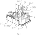
- the present embodiment provides a telescopic mechanism of a European plug of a power converter with a grounding pin, comprising a shell 1, a push handle 2 arranged on the shell 1, a plug bush 3 arranged in the shell 1 and movably connected with the push handle 2, and a pin assembly 4 arranged in the shell 1.
- the telescopic mechanism of the European plug of the power converter with the grounding pin in the embodiment further comprises a fixed rack 5 arranged on the shell 1 and extending into the plug bush 3, a movable rack 6 connected with the pin assembly 4, and a gear 7 arranged on the plug bush 3 and meshed with the fixed rack 5 and the movable rack 6 respectively. As shown in Figs.
- the plug bush 3 and the pin assembly 4 are in a non-push-out state.
- the push handle 2 drives the plug bush 3 to move downwards, and the gear 7 on the plug bush 3 moves downwards. Since the fixed rack 5 is fixed on the shell 1, the continuously moved gear 7 can roll along the fixed rack 5, for example, rotate in direction A (counterclockwise) in Fig. 2 .
- the movable rack 6 is also driven to synchronously move downwards when the gear 7 continuously moves downwards along with the plug bush 3 and passes out of the shell 1, and then the movable rack 6 drives the pin assembly 4 to synchronously move downwards for a first stroke, so that the pin assembly 4 and the plug bush 3 synchronously pass out of the shell 1; meanwhile, when the gear 7 rotates due to the presence of the fixed rack 5, the gear 7 synchronously pushes the movable rack 6 meshed with the gear 7 downwards, the movable rack 6 drives the pin assembly 4 to synchronously move downwards for a second stroke, and the pin assembly 4 moves downwards for the second stroke relative to the plug bush 3, so that a lower end of the pin assembly 4 passes out of the plug bush 3, as shown in Figs. 6-8 .
- the pin assembly 4 can also acquire a second stroke which moves downwards relative to the plug bush 3, so that the lower end of the pin assembly 4 passes out of the plug bush 3, i.e. the pin assembly 4 can acquire two strokes.
- the stroke of the push handle 2 can be set to be shorter when the plug bush 3 and the pin assembly 4 are pushed out similarly, so that the space occupied by the movement of the push handle 2 is reduced, the inner space of a product is saved, and the size of the product is reduced conveniently, which facilitates the miniaturization of the whole product.
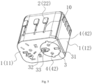
- the pin assembly 4 comprises two pins 42, two ground conductors 31, 32 are arranged on the plug bush 3, the two pins 42 and the two ground conductors 31, 32 are combined to form a hybrid grounding plug, and an additional contact sleeve 33 is provided on the hybrid grounding plug for a grounding pin of a French plug.
- the movable rack 6 is fixedly connected with the pin assembly 4.
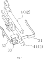
- the pin assembly 4 further comprises a transverse connection block 41, and the two pins 42 are perpendicularly arranged at a lower end of the transverse connection block 41, wherein the movable rack 6 is fixedly connected with the transverse connection block 41. Therefore, the movable rack 6 is integrally connected with the transverse connection block 41, and when the movable rack 6 moves downwards, the pin assembly 4 is driven to move downwards synchronously.
- the gear 7 is fixed to the plug bush 3. Specifically, as shown in Fig. 2 , the gear 7 is fixed to the plug bush 3 by a screw 71. Of course, the gear 7 may be fixed to the plug bush 3 by other structures or other means. Therefore, the gear 7 is integrally connected with the plug bush 3, and when the plug bush 3 moves downwards, the gear 7 is driven to move downwards synchronously.
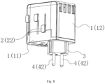
- the shell 1 comprises a base 11 and an upper cover 12 matched with the base 11, wherein an opening through which the plug bush 3 and the pin assembly 4 pass is formed in the base 11; and when the plug bush 3 and the pin assembly 4 are not pushed out, lower end surfaces of the plug bush 3 and the pin assembly 4 are flush with the opening, as shown in Fig. 5 . After the plug bush 3 and the pin assembly 4 are pushed out, lower parts of the plug bush 3 and the pin assembly 4 pass out of a lower end surface of the base 11 through the opening, as shown in Fig. 8 .
- the fixed rack 5 For the specific mounting of the fixed rack 5, it may be integrally formed on the base 11, or the fixed rack 5 may be longitudinally and fixedly mounted on the base 11 by a connector 51, so that the gear 7 can be meshed with the fixed rack 5, and the gear 7 can roll up and down along the fixed rack 5, as shown in Fig. 2 .
- the specific structure and configuration of the connector 51 can be set according to specific requirements, as shown in Figs. 2 and 6 .
- the telescopic mechanism provided by the embodiment of the invention is particularly suitable for a conversion plug, and the synchronous push-out function is realized for the plug bush 3 and the pin assembly 4 in the plug.
- the plug bush 3 and the pin assembly 4 can be pushed out only by pushing the push handle 2 downwards, and the plug bush 3 and the pin assembly 4 can be retracted by pushing the push handle 2 upwards.
- the plug bush 3 and the pin assembly 4 can be pushed out only by pushing the push handle 2 downwards, and the plug bush 3 and the pin assembly 4 can be retracted by pushing the push handle 2 upwards.
- the conventional conversion plug in the art.
- the telescopic mechanism provided by the embodiment is particularly suitable for use in European conversion plugs, such as German or French conversion plugs, particularly for use in high power appliances below 16 A.
- a locking structure 9 is arranged between the push handle 2 and the movable rack 6 and comprises at least one locking protrusion 91 arranged on the push handle 2 and at least one locking slot 92 formed on the movable rack 6 and used for clamping the locking protrusion 91.
- the locking protrusions 91 of the locking structure 9 are clamped into the locking slot 92, so that the movable rack 6 and the pin assembly 4 are integrally locked, and the movable rack 6 and the pin assembly 4 cannot be automatically retracted, which is convenient for the product use; and the two pins 42 of the pin assembly 4 and the plug bush 3 can be retracted into the shell 1 only if the locking protrusion 91 leaves the locking slot 92 to release the locking by pushing the push handle 2.
- the locking protrusion 91 of the locking structure 9 is clamped into the locking slot 92, so that the movable rack 6 and the pin assembly 4 are integrally locked, and the two pins 42 and the plug bush 3 cannot extend out automatically; and the two pins 42 and the plug bush 3 can be pushed out of the shell 1 only if the locking protrusion 91 leaves the locking slot 92 to release the locking by pushing the push handle 2.
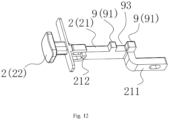
- the number of the locking protrusions 91 in the embodiment is two, and an avoiding slot 93 is formed between the two locking protrusions 91; accordingly, the number of the locking slot 92 is also two; and a longitudinal slide slot 94 extending longitudinally is formed in the movable rack 6, and the two locking slots 92 are located at both sides of the longitudinal slide slot, as shown in Figs. 11 and 12 .
- a locked state the two locking protrusions 91 are clamped into the two locking slots 92 one by one; and in a contact locked state, one locking protrusion 91 is located in the longitudinal slide slot 94, and the other locking protrusion 91 is also moved to the side of the movable rack 6.
- the push handle 2 is movably connected with the plug bush 3 by a positioning seat 30, and a positioning slide hole 301 and a spring mounting slot 302 are respectively formed in the positioning seat 30; a positioning strip 211 which is slidably arranged in the positioning slide hole 301 and a push block 212 which is movable in the spring mounting slot 302 are formed in the push handle 2; and a spring 303 is arranged in the spring mounting slot 302, and the spring 303 is directly pushed by the push block 212.
- the push handle 2 slides on the positioning seat 30 to the locking protrusion 91 of the locking structure 9 for being clamped into the locking slot 92, so that the movable rack 6 and the pin assembly 4 are integrally locked.
- the push handle 2 is pushed into the shell 1, so that the locking protrusion 91 leaves the locking slot 92 to release the locking.
- the two pins 42 of the pin assembly and the plug bush 3 can be pushed out and retracted by pushing the push handle 2 up and down 4 while the spring 303 is compressed.
- the push handle 2 mainly consists of a linkage block 21 arranged in the shell 1 and a push part 22 connected to an end of the linkage block 21 and passing out of the shell 1, wherein the linkage block 21 is movably connected with the plug bush 3 by the positioning seat 30; and the locking protrusion 91, the positioning strip 211 and the push block 212 are all arranged on the linkage block 21. Therefore, when the linkage block 21 of the push handle 2 moves downwards, the plug bush 3 is driven to move downwards synchronously. Meanwhile, as shown in Fig. 5 , a strip-shaped hole 10 for the push part 22 to move up and down is formed in the shell 1, and the strip-shaped hole 10 provides a vertical path for the push part 22 to move up and down.
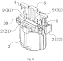
- At least one guide rod 8 is arranged in the shell 1, and the linkage block 21 and the positioning seat 30 are sleeved on the guide rod 8, as shown in Figs. 3 and 10 .
- the linkage block 21 can vertically move up and down along a plurality of guide rods 8, without the phenomena of displacement, bending and the like.
Landscapes
- Details Of Connecting Devices For Male And Female Coupling (AREA)
- Input Circuits Of Receivers And Coupling Of Receivers And Audio Equipment (AREA)
- Transmission Devices (AREA)
- Connector Housings Or Holding Contact Members (AREA)
Description
- The invention relates to the field of conversion plugs, in particular to a telescopic mechanism of a European plug of a power converter with a grounding pin.
- With the increasing global tourism and trade, travel conversion plugs or travel converters have been widely used. With the development of technology, the types and functions of conversion plugs are constantly updated, for example, German conversion plugs.
- However, due to the limitation of the internal structure design, the German conversion plug has the following disadvantages: when pins are pushed out for use, a push handle needs to be pushed to move for a stroke to push an plug bush to pass out of the shell; then, the push handle is pushed to move for a next stroke, so that the pins can be pushed out of the shell and out of a lower end of the plug bush for use. Therefore, with the structure having a large position and space to be reserved on the German conversion plug, the push handle can complete two strokes. Therefore, the occupied space is larger, and the size of the product is bigger, which does not facilitate the miniaturization development of the product.
-
WO2018064780 discloses a travel plug for establishing an electrical connection between plugs and sockets complying with the standards of different countries, comprising a housing having at least one socket for inserting an electrical plug and at least one plug complying with a country standard, which can be retracted and extended from the housing and electrically connected to the socket, said plug being linearly displaceable by means of an adjusting part, which projects from the housing and is mechanically connected to the plug. The travel plug also comprises a mechanical gear, which connects the adjusting part to the displaceable plug and transmits the path of the adjusting part to the linear displacement path of the plug. - For the defects above, the invention is directed to provide telescopic mechanism of a European plug of a power converter with a grounding pin, wherein the stroke of the push handle can be set to be shorter when the plug bush and the pin assembly are pushed out similarly, so that the space occupied by the movement of the push handle is reduced, the inner space of a product is saved, and the size of the product is reduced conveniently, which facilitates the miniaturization of the whole product.
- The technical solution adopted by the invention for achieving the above purpose is as follows.
- A telescopic mechanism of a European plug of a power converter with a grounding pin comprises a shell, a push handle arranged on the shell, a plug bush arranged in the shell and connected with the push handle, and a pin assembly arranged in the shell, characterized by further comprising a fixed rack arranged on the shell and extending into the plug bush, a movable rack connected with the pin assembly and a gear fixed on the plug bush; wherein the movable rack and the fixed rack both have teeth; the gear meshes with the fixed rack and the movable rack through the teeth respectively. The push handle drives the plug bush and the gear fixed on the plug bush to move; the gear drives the movable rack to move; and the movable rack drives the pin assembly to move.
- As a further improvement of the present invention, the pin assembly comprises two pins, two ground conductors are arranged on the plug bush, the two pins and the two ground conductors are combined to form a hybrid grounding plug, and an additional contact sleeve is provided on the hybrid grounding plug for a grounding pin of a French plug.
- As a further improvement of the present invention, the movable rack is fixedly connected with the pin assembly.
- As a further improvement of the invention, the pin assembly further comprises a transverse connection block, and the two pins are perpendicularly arranged at a lower end of the transverse connection block, wherein the movable rack is fixedly connected with the transverse connection block.
- According to the present invention, the gear is fixed to the plug bush.
- As a further improvement of the present invention, the gear is fixed to the plug bush by a screw.
- As a further improvement of the present invention, the shell comprises a base and an upper cover matched with the base, wherein an opening through which the plug bush and the pin assembly pass is formed in the base.
- As a further improvement of the present invention, the fixed rack is integrally formed on the base, or longitudinally and fixedly mounted on the base by a connector.
- As a further improvement of the present invention, the fixed rack is longitudinally fixed to the upper cover.
- As a further improvement of the invention, a locking structure is arranged between the push handle and the movable rack and comprises at least one locking protrusion arranged on the push handle and at least one locking slot formed on the movable rack and used for clamping the locking protrusion.
- As a further improvement of the invention, the push handle is movably connected with the plug bush by a positioning seat, and a positioning slide hole and a spring mounting slot are respectively formed in the positioning seat; and a positioning strip which is slidably arranged in the positioning slide hole and a push block which is movable in the spring mounting slot are formed in the push handle, and a spring is arranged in the spring mounting slot.
- As a further improvement of the invention, the push handle mainly consists of a linkage block arranged in the shell and a push part connected to an end of the linkage block and passing out of the shell, wherein the linkage block is movably connected with the plug bush by the positioning seat; the locking protrusion, the positioning strip and the push block are all arranged on the linkage block; meanwhile, a strip-shaped hole for the push part to move up and down is formed in the shell.
- As a further improvement of the invention, at least one guide rod is arranged in the shell, and the linkage block and the positioning seat are sleeved on the guide rod.
- The invention has following beneficial effects. By additionally arranging and combining the fixed rack, the gear and the movable rack meshed with each other, as long as the push handle is pushed downwards to move for a first stroke, the first downward stroke can be provided for the plug bush and the pin assembly, namely the plug bush and the pin assembly are pushed out of the shell synchronously; meanwhile, the pin assembly can also acquire a second stroke which moves downwards relative to the plug bush, so that the lower end of the pin assembly passes out of the plug bush, i.e. the push handle moves for one stroke, and the pin assembly can acquire two strokes. As can be seen from this, the stroke of the push handle can be set to be shorter when the plug bush and the pin assembly are pushed out similarly, so that the space occupied by the movement of the push handle is reduced, the inner space of a product is saved, and the size of the product is reduced conveniently, which facilitates the miniaturization of the whole product.
- The above is an overview of the technical scheme of the invention. The following is a further explanation of the invention in combination with the attached drawings and specific implementations.
-
-
Fig. 1 is an overall exploded view according toEmbodiment 1; -
Fig. 2 is a schematic view showing the internal structure of a plug bush and a pin assembly in a non-push-out state according toEmbodiment 1; -
Fig. 3 is a structurally schematic view of a linkage block of a push handle sleeved on a guide rod according toEmbodiment 1; -
Fig. 4 is a schematic view showing the structure that a movable rack, a gear and a fixed rack are combined when the plug bush and the pin assembly are in the non-push-out state according toEmbodiment 1; -
Fig. 5 is a schematic view showing the overall external structure of the plug bush and pin assembly in the non-push-out state according toEmbodiment 1; -
Fig. 6 is a schematic view showing the internal structure of the plug bush and the pin assembly in a push-out state according toEmbodiment 1; -
Fig. 7 is a structurally schematic view of the movable rack, the gear and the fixed rack are combined when the plug bush and the pin assembly are in the push-out state according toEmbodiment 1; -
Fig. 8 is a schematic view showing the overall external structure of the plug bush and the pin assembly in the push-out state according toEmbodiment 1; -
Fig. 9 is a structurally schematic view of a hybrid grounding plug according toEmbodiment 1; -
Fig. 10 is a structurally schematic view of a locking structure arranged on a push handle and a movable rack according toEmbodiment 2; -
Fig. 11 is a schematic view showing an exploded structure of the push handle, the movable rack and a positioning seat according toEmbodiment 2; -
Fig. 12 is a structurally schematic view of the push handle according toEmbodiment 2. - In order to further explain the technical means and effects of the present invention for achieving the intended purpose, the following detailed description of the embodiments of the present invention will be made with reference to the accompanying drawings and preferred embodiments.
- Referring to
Figs. 1 ,2 and4 , the present embodiment provides a telescopic mechanism of a European plug of a power converter with a grounding pin, comprising ashell 1, apush handle 2 arranged on theshell 1, aplug bush 3 arranged in theshell 1 and movably connected with thepush handle 2, and apin assembly 4 arranged in theshell 1. The telescopic mechanism of the European plug of the power converter with the grounding pin in the embodiment further comprises a fixedrack 5 arranged on theshell 1 and extending into theplug bush 3, amovable rack 6 connected with thepin assembly 4, and agear 7 arranged on theplug bush 3 and meshed with the fixedrack 5 and themovable rack 6 respectively. As shown inFigs. 2 ,4 and5 , theplug bush 3 and thepin assembly 4 are in a non-push-out state. When thepush handle 2 is pushed downwards, thepush handle 2 drives theplug bush 3 to move downwards, and thegear 7 on theplug bush 3 moves downwards. Since thefixed rack 5 is fixed on theshell 1, the continuously movedgear 7 can roll along thefixed rack 5, for example, rotate in direction A (counterclockwise) inFig. 2 . In the process, as thegear 7 is in meshed connection with themovable rack 6, themovable rack 6 is also driven to synchronously move downwards when thegear 7 continuously moves downwards along with theplug bush 3 and passes out of theshell 1, and then themovable rack 6 drives thepin assembly 4 to synchronously move downwards for a first stroke, so that thepin assembly 4 and theplug bush 3 synchronously pass out of theshell 1; meanwhile, when thegear 7 rotates due to the presence of thefixed rack 5, thegear 7 synchronously pushes themovable rack 6 meshed with thegear 7 downwards, themovable rack 6 drives thepin assembly 4 to synchronously move downwards for a second stroke, and thepin assembly 4 moves downwards for the second stroke relative to theplug bush 3, so that a lower end of thepin assembly 4 passes out of theplug bush 3, as shown inFigs. 6-8 . - Therefore, as long as the
push handle 2 is pushed downwards to move for the first stroke, the first downward stroke can be provided for theplug bush 3 and thepin assembly 4, namely theplug bush 3 and thepin assembly 4 are pushed out of theshell 1 synchronously; meanwhile, thepin assembly 4 can also acquire a second stroke which moves downwards relative to theplug bush 3, so that the lower end of thepin assembly 4 passes out of theplug bush 3, i.e. thepin assembly 4 can acquire two strokes. As can be seen from this, the stroke of thepush handle 2 can be set to be shorter when theplug bush 3 and thepin assembly 4 are pushed out similarly, so that the space occupied by the movement of thepush handle 2 is reduced, the inner space of a product is saved, and the size of the product is reduced conveniently, which facilitates the miniaturization of the whole product. - In this embodiment, as shown in
Figs. 5 and9 , thepin assembly 4 comprises twopins 42, twoground conductors plug bush 3, the twopins 42 and the twoground conductors additional contact sleeve 33 is provided on the hybrid grounding plug for a grounding pin of a French plug. By means of the meshed structure formed by combining the fixedrack 5, themovable rack 6 and thegear 7, the pin in the hybrid grounding plug can be telescopically operated. - In this embodiment, the
movable rack 6 is fixedly connected with thepin assembly 4. Specifically, as shown inFig. 2 , thepin assembly 4 further comprises atransverse connection block 41, and the twopins 42 are perpendicularly arranged at a lower end of thetransverse connection block 41, wherein themovable rack 6 is fixedly connected with thetransverse connection block 41. Therefore, themovable rack 6 is integrally connected with thetransverse connection block 41, and when themovable rack 6 moves downwards, thepin assembly 4 is driven to move downwards synchronously. - In this embodiment, the
gear 7 is fixed to theplug bush 3. Specifically, as shown inFig. 2 , thegear 7 is fixed to theplug bush 3 by ascrew 71. Of course, thegear 7 may be fixed to theplug bush 3 by other structures or other means. Therefore, thegear 7 is integrally connected with theplug bush 3, and when theplug bush 3 moves downwards, thegear 7 is driven to move downwards synchronously. - In the embodiment, as shown in
Fig. 1 , theshell 1 comprises abase 11 and anupper cover 12 matched with thebase 11, wherein an opening through which theplug bush 3 and thepin assembly 4 pass is formed in thebase 11; and when theplug bush 3 and thepin assembly 4 are not pushed out, lower end surfaces of theplug bush 3 and thepin assembly 4 are flush with the opening, as shown inFig. 5 . After theplug bush 3 and thepin assembly 4 are pushed out, lower parts of theplug bush 3 and thepin assembly 4 pass out of a lower end surface of the base 11 through the opening, as shown inFig. 8 . - For the specific mounting of the fixed
rack 5, it may be integrally formed on thebase 11, or the fixedrack 5 may be longitudinally and fixedly mounted on thebase 11 by aconnector 51, so that thegear 7 can be meshed with the fixedrack 5, and thegear 7 can roll up and down along the fixedrack 5, as shown inFig. 2 . The specific structure and configuration of theconnector 51 can be set according to specific requirements, as shown inFigs. 2 and6 . Of course, it is also possible to fix the fixedrack 5 longitudinally on theupper cover 12 as long as the fixedrack 5 can extend to the side of thegear 7 for being meshed with thegear 7, and thegear 7 can roll up and down along the fixedrack 5. - The telescopic mechanism provided by the embodiment of the invention is particularly suitable for a conversion plug, and the synchronous push-out function is realized for the
plug bush 3 and thepin assembly 4 in the plug. During specific operations, theplug bush 3 and thepin assembly 4 can be pushed out only by pushing the push handle 2 downwards, and theplug bush 3 and thepin assembly 4 can be retracted by pushing the push handle 2 upwards. However, with regard to other structures and working principles inside the conversion plug, the same is true of the conventional conversion plug in the art. - Preferably, the telescopic mechanism provided by the embodiment is particularly suitable for use in European conversion plugs, such as German or French conversion plugs, particularly for use in high power appliances below 16 A.
- The main difference between this embodiment and
Embodiment 1 is that, as shown inFigs. 10 to 12 , a lockingstructure 9 is arranged between thepush handle 2 and themovable rack 6 and comprises at least one lockingprotrusion 91 arranged on thepush handle 2 and at least onelocking slot 92 formed on themovable rack 6 and used for clamping the lockingprotrusion 91. After the twopins 42 of thepin assembly 4 and theplug bush 3 extend out of theshell 1 or are retracted into theshell 1, the twopins 42 and theplug bush 3 of thepin assembly 4 can be clamped into the lockingslot 92 by the lockingprotrusion 91 of the lockingstructure 9, so that themovable rack 6 and thepin assembly 4 can be integrally locked, which is convenient for the product use. For example, after the twopins 42 of thepin assembly 4 and theplug bush 3 extend out of theshell 1, the lockingprotrusions 91 of the lockingstructure 9 are clamped into the lockingslot 92, so that themovable rack 6 and thepin assembly 4 are integrally locked, and themovable rack 6 and thepin assembly 4 cannot be automatically retracted, which is convenient for the product use; and the twopins 42 of thepin assembly 4 and theplug bush 3 can be retracted into theshell 1 only if the lockingprotrusion 91 leaves the lockingslot 92 to release the locking by pushing thepush handle 2. Similarly, after the two pins4 of thepin assembly 42 and theplug bush 3 are retracted into theshell 1, the lockingprotrusion 91 of the lockingstructure 9 is clamped into the lockingslot 92, so that themovable rack 6 and thepin assembly 4 are integrally locked, and the twopins 42 and theplug bush 3 cannot extend out automatically; and the twopins 42 and theplug bush 3 can be pushed out of theshell 1 only if the lockingprotrusion 91 leaves the lockingslot 92 to release the locking by pushing thepush handle 2. - Specifically, the number of the locking
protrusions 91 in the embodiment is two, and an avoidingslot 93 is formed between the two lockingprotrusions 91; accordingly, the number of the lockingslot 92 is also two; and alongitudinal slide slot 94 extending longitudinally is formed in themovable rack 6, and the two lockingslots 92 are located at both sides of the longitudinal slide slot, as shown inFigs. 11 and12 . In a locked state, the two lockingprotrusions 91 are clamped into the two lockingslots 92 one by one; and in a contact locked state, one lockingprotrusion 91 is located in thelongitudinal slide slot 94, and the other lockingprotrusion 91 is also moved to the side of themovable rack 6. - In the embodiment, the push handle 2 is movably connected with the
plug bush 3 by apositioning seat 30, and apositioning slide hole 301 and aspring mounting slot 302 are respectively formed in thepositioning seat 30; apositioning strip 211 which is slidably arranged in thepositioning slide hole 301 and apush block 212 which is movable in thespring mounting slot 302 are formed in thepush handle 2; and aspring 303 is arranged in thespring mounting slot 302, and thespring 303 is directly pushed by thepush block 212. In a natural telescopic state of thespring 303, the push handle 2 slides on thepositioning seat 30 to the lockingprotrusion 91 of the lockingstructure 9 for being clamped into the lockingslot 92, so that themovable rack 6 and thepin assembly 4 are integrally locked. When it is required to release the locking, the push handle 2 is pushed into theshell 1, so that the lockingprotrusion 91 leaves the lockingslot 92 to release the locking. Thus, the twopins 42 of the pin assembly and theplug bush 3 can be pushed out and retracted by pushing the push handle 2 up and down 4 while thespring 303 is compressed. After the push handle 2 is pushed up and down to be in place, the acting force on the push handle 2 is released; and under the elastic restoring force of thespring 303, the push handle 2 is moved outwards and reset, so that the push handle 2 slides on thepositioning seat 30, and the lockingprotrusion 91 of the lockingstructure 9 is clamped into the lockingslot 92 again for realizing the locking function. - In the embodiment, as shown in
Figs. 2 ,10 and12 , the push handle 2 mainly consists of alinkage block 21 arranged in theshell 1 and apush part 22 connected to an end of thelinkage block 21 and passing out of theshell 1, wherein thelinkage block 21 is movably connected with theplug bush 3 by the positioningseat 30; and the lockingprotrusion 91, thepositioning strip 211 and thepush block 212 are all arranged on thelinkage block 21. Therefore, when thelinkage block 21 of the push handle 2 moves downwards, theplug bush 3 is driven to move downwards synchronously. Meanwhile, as shown inFig. 5 , a strip-shapedhole 10 for thepush part 22 to move up and down is formed in theshell 1, and the strip-shapedhole 10 provides a vertical path for thepush part 22 to move up and down. - In order to improve the vertical stability of the push handle 2 moving up and down, at least one
guide rod 8 is arranged in theshell 1, and thelinkage block 21 and thepositioning seat 30 are sleeved on theguide rod 8, as shown inFigs. 3 and10 . When the push handle 2 moves up and down, thelinkage block 21 can vertically move up and down along a plurality ofguide rods 8, without the phenomena of displacement, bending and the like.
In the description above, only the preferred embodiments of the present invention has been described, and the technical scope of the present invention is not limited in any way. Therefore, other structures obtained by adopting the same or similar technical features as those of the above embodiments of the present invention are within the scope of the present invention.
Claims (12)
- A telescopic mechanism of a European plug of a power converter with a grounding pin, comprising a shell (1), a push handle (2) arranged on the shell (1), a plug bush (3) arranged in the shell (1) and connected with the push handle (2), and a pin assembly (4) arranged in the shell (1), characterized by further comprisinga fixed rack (5) arranged on the shell (1) and extending into the plug bush (3),a movable rack (6) connected with the pin assembly (4) anda gear (7) fixed on the plug bush (3); whereinthe movable rack (6) and the fixed rack (5) both have teeth; the gear (7) meshes with the fixed rack (5) and the movable rack (6) through the teeth respectively; the push handle (2) drives the plug bush (3) and the gear (7) fixed on the plug bush (3) to move; the gear (7) drives the movable rack (6) to move; and the movable rack (6) drives the pin assembly (4) to move.
- The telescopic mechanism of a European plug of a power converter with a grounding pin according to claim 1, characterized in that the pin assembly (4) comprises two pins (42), two ground conductors (31, 32) are arranged on the plug bush (3), the two pins (42) and the two ground conductors (31, 32) are combined to form a hybrid grounding plug, and an additional contact sleeve (33) is provided on the hybrid grounding plug for a grounding pin of a French plug.
- The telescopic mechanism of a European plug of a power converter with a grounding pin according to claim 2, characterized in that the movable rack (6) is fixedly connected with the pin assembly (4).
- The telescopic mechanism of a European plug of a power converter with a grounding pin according to claim 3, characterized in that the pin assembly (4) further comprises a transverse connection block (41), and the two pins (42) are perpendicularly arranged at a lower end of the transverse connection block (41), wherein the movable rack (6) is fixedly connected with the transverse connection block (41).
- The telescopic mechanism of a European plug of a power converter with a grounding pin according to claim 1, characterized in that the gear (7) is fixed to the plug bush (3) by a screw (71).
- The telescopic mechanism of a European plug of a power converter with a grounding pin according to claim 1, characterized in that the shell (1) comprises a base (11) and an upper cover (12) matched with the base (11), wherein an opening through which the plug bush (3) and the pin assembly (4) pass is formed in the base (11).
- The telescopic mechanism of a European plug of a power converter with a grounding pin according to claim 6, characterized in that the fixed rack (5) is integrally formed on the base (11), or longitudinally fixed on the base (11) by a connector (51).
- The telescopic mechanism of a European plug of a power converter with a grounding pin according to claim 6, characterized in that the fixed rack (5) is longitudinally fixed to the upper cover (12).
- The telescopic mechanism of a European plug of a power converter with a grounding pin according to any one of claims 1 to 8, characterized in that a locking structure (9) is arranged between the push handle (2) and the movable rack (6) and comprises at least one locking protrusion (91) arranged on the push handle (2) and at least one locking slot (92) formed on the movable rack (6) and used for clamping the locking protrusion (91).
- The telescopic mechanism of a European plug of a power converter with a grounding pin according to claim 9, characterized in that the push handle (2) is movably connected with the plug bush (3) by a positioning seat (30), and a positioning slide hole (301) and a spring mounting slot (302) are respectively formed in the positioning seat (30); and a positioning strip (211) which is slidably arranged in the positioning slide hole (301) and a push block (212) which is movable in the spring mounting slot (302) are formed in the push handle (2), and a spring (303) is arranged in the spring mounting slot (302).
- The telescopic mechanism of a European plug of a power converter with a grounding pin according to claim 10, characterized in that the push handle (2) mainly consists of a linkage block (21) arranged in the shell (1) and a push part (22) connected to an end of the linkage block (21) and passing out of the shell (1), wherein the linkage block (21) is movably connected with the plug bush (3) by the positioning seat (30); the locking protrusion (91), the positioning strip (211) and the push block (212) are all arranged on the linkage block (21); meanwhile, a strip-shaped hole (10) for the push part (22) to move up and down is formed in the shell (1).
- The telescopic mechanism of a European plug of a power converter with a grounding pin according to claim 11, characterized in that at least one guide rod (8) is arranged in the shell (1), and the linkage block (21) and the positioning seat (30) are sleeved on the guide rod (8).
Applications Claiming Priority (2)
| Application Number | Priority Date | Filing Date | Title |
|---|---|---|---|
| CN202010285974.4A CN111478110A (en) | 2020-04-13 | 2020-04-13 | A conversion plug extension mechanism |
| CN202110372273.9A CN113161805B (en) | 2020-04-13 | 2021-04-07 | Telescopic mechanism for a European-style plug of a power converter with a grounding pin. |
Publications (3)
| Publication Number | Publication Date |
|---|---|
| EP3896802A1 EP3896802A1 (en) | 2021-10-20 |
| EP3896802C0 EP3896802C0 (en) | 2023-12-06 |
| EP3896802B1 true EP3896802B1 (en) | 2023-12-06 |
Family
ID=71752234
Family Applications (1)
| Application Number | Title | Priority Date | Filing Date |
|---|---|---|---|
| EP21167937.8A Active EP3896802B1 (en) | 2020-04-13 | 2021-04-12 | Telescopic mechanism of european plug of power converter with grounding pin |
Country Status (14)
| Country | Link |
|---|---|
| US (1) | US11489302B2 (en) |
| EP (1) | EP3896802B1 (en) |
| JP (1) | JP3241164U (en) |
| KR (1) | KR200497471Y1 (en) |
| CN (3) | CN111478110A (en) |
| AU (1) | AU2021101880A4 (en) |
| CA (1) | CA3114619C (en) |
| ES (1) | ES2973139T3 (en) |
| GB (1) | GB2592771B (en) |
| HU (1) | HUE065653T2 (en) |
| IL (1) | IL296871B2 (en) |
| PL (1) | PL3896802T3 (en) |
| SA (1) | SA522440902B1 (en) |
| WO (1) | WO2021208311A1 (en) |
Families Citing this family (15)
| Publication number | Priority date | Publication date | Assignee | Title |
|---|---|---|---|---|
| CN111478110A (en) * | 2020-04-13 | 2020-07-31 | 东莞市佳旅电器有限公司 | A conversion plug extension mechanism |
| CA200784S (en) * | 2020-07-24 | 2022-08-23 | Dongguan Best Travel Electronics Co Ltd | Power adapter |
| CN112864689B (en) * | 2021-01-05 | 2023-06-23 | 深圳市绿联科技股份有限公司 | Storable power plug, patch board and electric appliance |
| CN114006235B (en) * | 2021-11-15 | 2025-05-20 | 深圳市欧力科技有限公司 | A kind of converter |
| CN115616304B (en) * | 2022-09-22 | 2024-07-02 | 国网山东省电力公司淄博供电公司 | One-key type low-voltage dual-power intelligent phase checking device |
| USD1082687S1 (en) * | 2022-09-30 | 2025-07-08 | Feng Wang | Electrical plug |
| USD1103920S1 (en) * | 2022-09-30 | 2025-12-02 | Feng Wang | Electrical plug |
| USD1007432S1 (en) * | 2023-01-20 | 2023-12-12 | Feng Wang | Socket |
| CN116267278B (en) * | 2023-04-25 | 2024-05-24 | 河北省农林科学院石家庄果树研究所 | Grape branch contour trimming means |
| USD1052531S1 (en) * | 2023-06-08 | 2024-11-26 | Yanli Zhang | Electric socket |
| USD1018073S1 (en) * | 2023-11-21 | 2024-03-19 | Huashan Zhong | Voltage converter |
| TWM666194U (en) * | 2023-12-13 | 2025-02-11 | 大陸商東莞市佳旅電器有限公司 | An anti-electric shock shield structure for a plug assembly |
| CN118156881B (en) * | 2024-04-08 | 2025-02-14 | 深圳市欧力科技有限公司 | A travel converter |
| CN118281625B (en) * | 2024-04-08 | 2024-11-29 | 深圳市欧力科技有限公司 | Telescopic structure of European plug of power converter |
| CN118336422B (en) * | 2024-05-17 | 2024-09-06 | 东莞市燊瑞电子科技有限公司 | A magnetic hidden charging base |
Citations (10)
| Publication number | Priority date | Publication date | Assignee | Title |
|---|---|---|---|---|
| EP1387448A2 (en) | 2002-08-01 | 2004-02-04 | Comarco Wireless Technologies, Inc. | Foldable electrical plug connector |
| CN2692880Y (en) | 2004-01-18 | 2005-04-13 | 廖生兴 | Multi-function plug converter |
| US7220139B1 (en) | 2006-07-04 | 2007-05-22 | Hsi-Fan Chang | Universal power adapter |
| WO2013038204A1 (en) | 2011-09-16 | 2013-03-21 | Dg International Holdings Limited | Adaptor |
| EP3252884A1 (en) | 2016-06-01 | 2017-12-06 | Travel Blue Limited | Compact travelling plug |
| CN107611684A (en) | 2017-09-19 | 2018-01-19 | 广州万浦电器有限公司 | A kind of scalable plug of multipurpose and combination type conversion socket |
| WO2018064780A1 (en) | 2016-10-07 | 2018-04-12 | Q2Power Ag | Travel plug |
| EP3316422A1 (en) | 2016-11-01 | 2018-05-02 | Travel Blue Limited | Comfortable to operate travel adapter |
| US20190288437A1 (en) | 2017-03-17 | 2019-09-19 | Cable Gear Holdings Llc | Electrical plug and adapter with retractable prongs |
| EP3671979A1 (en) | 2018-12-21 | 2020-06-24 | WorldConnect AG | Travel adapter and set comprising a travel adapter |
Family Cites Families (14)
| Publication number | Priority date | Publication date | Assignee | Title |
|---|---|---|---|---|
| CN201160004Y (en) * | 2008-01-22 | 2008-12-03 | 富士康(昆山)电脑接插件有限公司 | mobile storage device |
| CN102150332B (en) * | 2008-06-17 | 2013-10-30 | 华特·鲁夫拿 | Multi-way sliding plug |
| CN100568637C (en) | 2008-11-21 | 2009-12-09 | 深圳市派高模业有限公司 | A plug socket adapter |
| CN101872911B (en) * | 2010-05-18 | 2012-11-07 | 智嘉通讯科技(东莞)有限公司 | Rotary selection push-out type multinational power supply adapter |
| CN104601744A (en) * | 2013-10-31 | 2015-05-06 | 富泰华工业(深圳)有限公司 | Mobile terminal with ejecting mechanism |
| SE537610C2 (en) * | 2013-11-20 | 2015-07-28 | Eazyplug Ab | Electric plug |
| CN207474762U (en) * | 2017-11-15 | 2018-06-08 | 广州万浦电器有限公司 | Multifunctional conversion plug and combination type conversion socket |
| CN207925793U (en) * | 2018-03-20 | 2018-09-28 | 上海工程技术大学 | A kind of modified form two-pin plug |
| CN109524817A (en) * | 2018-11-20 | 2019-03-26 | 许汉平 | A kind of scalable plug |
| CN209608375U (en) * | 2019-05-23 | 2019-11-08 | 深圳市盈辉电子有限公司 | An easily adjustable mobile phone adapter |
| CN110098533A (en) * | 2019-06-10 | 2019-08-06 | 贵州工程应用技术学院 | A kind of easily singlehanded plug extracted of protection against electric shock |
| CN110571600A (en) * | 2019-09-28 | 2019-12-13 | 胡伟 | Intelligent plug and socket assembly |
| CN110994309B (en) * | 2020-01-02 | 2024-07-23 | 东莞永旅电器科技有限公司 | Multifunctional adapter plug |
| CN111478110A (en) * | 2020-04-13 | 2020-07-31 | 东莞市佳旅电器有限公司 | A conversion plug extension mechanism |
-
2020
- 2020-04-13 CN CN202010285974.4A patent/CN111478110A/en active Pending
- 2020-08-19 IL IL296871A patent/IL296871B2/en unknown
- 2020-08-19 JP JP2022600031U patent/JP3241164U/en active Active
- 2020-08-19 WO PCT/CN2020/110062 patent/WO2021208311A1/en not_active Ceased
-
2021
- 2021-04-07 CN CN202120706153.3U patent/CN215008739U/en active Active
- 2021-04-07 CN CN202110372273.9A patent/CN113161805B/en active Active
- 2021-04-12 HU HUE21167937A patent/HUE065653T2/en unknown
- 2021-04-12 GB GB2105184.2A patent/GB2592771B/en active Active
- 2021-04-12 CA CA3114619A patent/CA3114619C/en active Active
- 2021-04-12 KR KR2020210001138U patent/KR200497471Y1/en active Active
- 2021-04-12 ES ES21167937T patent/ES2973139T3/en active Active
- 2021-04-12 EP EP21167937.8A patent/EP3896802B1/en active Active
- 2021-04-12 PL PL21167937.8T patent/PL3896802T3/en unknown
- 2021-04-12 US US17/228,610 patent/US11489302B2/en active Active
- 2021-04-13 AU AU2021101880A patent/AU2021101880A4/en active Active
-
2022
- 2022-10-12 SA SA522440902A patent/SA522440902B1/en unknown
Patent Citations (10)
| Publication number | Priority date | Publication date | Assignee | Title |
|---|---|---|---|---|
| EP1387448A2 (en) | 2002-08-01 | 2004-02-04 | Comarco Wireless Technologies, Inc. | Foldable electrical plug connector |
| CN2692880Y (en) | 2004-01-18 | 2005-04-13 | 廖生兴 | Multi-function plug converter |
| US7220139B1 (en) | 2006-07-04 | 2007-05-22 | Hsi-Fan Chang | Universal power adapter |
| WO2013038204A1 (en) | 2011-09-16 | 2013-03-21 | Dg International Holdings Limited | Adaptor |
| EP3252884A1 (en) | 2016-06-01 | 2017-12-06 | Travel Blue Limited | Compact travelling plug |
| WO2018064780A1 (en) | 2016-10-07 | 2018-04-12 | Q2Power Ag | Travel plug |
| EP3316422A1 (en) | 2016-11-01 | 2018-05-02 | Travel Blue Limited | Comfortable to operate travel adapter |
| US20190288437A1 (en) | 2017-03-17 | 2019-09-19 | Cable Gear Holdings Llc | Electrical plug and adapter with retractable prongs |
| CN107611684A (en) | 2017-09-19 | 2018-01-19 | 广州万浦电器有限公司 | A kind of scalable plug of multipurpose and combination type conversion socket |
| EP3671979A1 (en) | 2018-12-21 | 2020-06-24 | WorldConnect AG | Travel adapter and set comprising a travel adapter |
Non-Patent Citations (1)
| Title |
|---|
| ANONYMOUS: "Schuko ", WIKIPEDIA, 4 April 2020 (2020-04-04), pages 1 - 5, XP093208635, Retrieved from the Internet <URL:https://en.wikipedia.org/w/index.php?title=Schuko&oldid=949091240> [retrieved on 20240925] |
Also Published As
| Publication number | Publication date |
|---|---|
| CN113161805A (en) | 2021-07-23 |
| EP3896802C0 (en) | 2023-12-06 |
| EP3896802A1 (en) | 2021-10-20 |
| AU2021101880A4 (en) | 2021-06-03 |
| JP3241164U (en) | 2023-03-09 |
| US11489302B2 (en) | 2022-11-01 |
| IL296871A (en) | 2022-11-01 |
| HUE065653T2 (en) | 2024-06-28 |
| IL296871B1 (en) | 2025-01-01 |
| CN215008739U (en) | 2021-12-03 |
| KR20210002348U (en) | 2021-10-21 |
| GB202105184D0 (en) | 2021-05-26 |
| CN111478110A (en) | 2020-07-31 |
| GB2592771A (en) | 2021-09-08 |
| IL296871B2 (en) | 2025-05-01 |
| WO2021208311A1 (en) | 2021-10-21 |
| US20210320467A1 (en) | 2021-10-14 |
| KR200497471Y1 (en) | 2023-11-17 |
| PL3896802T3 (en) | 2024-06-10 |
| CA3114619A1 (en) | 2021-10-13 |
| SA522440902B1 (en) | 2024-01-24 |
| ES2973139T3 (en) | 2024-06-18 |
| CN113161805B (en) | 2026-01-09 |
| CA3114619C (en) | 2023-06-06 |
| GB2592771B (en) | 2023-03-29 |
Similar Documents
| Publication | Publication Date | Title |
|---|---|---|
| EP3896802B1 (en) | Telescopic mechanism of european plug of power converter with grounding pin | |
| US8684755B2 (en) | Electrical pop out device | |
| CN105261908B (en) | Socket adapter with telescopic plug | |
| CN105206993A (en) | Converter with retractably-stored plug | |
| CN105261907B (en) | A kind of telescopic earth polar latch converter | |
| CN204966897U (en) | Telescopic terrestrial pole bolt converter | |
| CN110011147A (en) | A plug-in convertible plug | |
| HK40059882A (en) | Telescopic mechanism of european plug of power converter with grounding pin | |
| CN204966913U (en) | Socket converter with telescopic plug | |
| TWM632685U (en) | European plug telescopic mechanism for power adapter having ground pin | |
| AU2024205582B2 (en) | Conversion and conduction structure for power converter. | |
| CN212392431U (en) | A conversion plug extension mechanism | |
| CN118156881B (en) | A travel converter | |
| CN223390917U (en) | Single plug extension limiting structure of multifunctional converter | |
| CN223206596U (en) | A multifunctional converter with compact plug layout | |
| CN222735844U (en) | Power Bank | |
| US20250323466A1 (en) | Pin assembly structure with multiple pin specifications | |
| CN110854580A (en) | Spring type socket with reliable and lasting reset function | |
| CN217607084U (en) | Combined protective door socket | |
| US20250309587A1 (en) | Socket Device | |
| US20250300390A1 (en) | Conversion Socket | |
| HK40118565A (en) | Conversion and conduction structure for power converter | |
| CN116387066A (en) | Electrical switch multi-contact assembly device | |
| CN205248526U (en) | Converter with button option function |
Legal Events
| Date | Code | Title | Description |
|---|---|---|---|
| PUAI | Public reference made under article 153(3) epc to a published international application that has entered the european phase |
Free format text: ORIGINAL CODE: 0009012 |
|
| STAA | Information on the status of an ep patent application or granted ep patent |
Free format text: STATUS: THE APPLICATION HAS BEEN PUBLISHED |
|
| AK | Designated contracting states |
Kind code of ref document: A1 Designated state(s): AL AT BE BG CH CY CZ DE DK EE ES FI FR GB GR HR HU IE IS IT LI LT LU LV MC MK MT NL NO PL PT RO RS SE SI SK SM TR |
|
| B565 | Issuance of search results under rule 164(2) epc |
Effective date: 20210909 |
|
| STAA | Information on the status of an ep patent application or granted ep patent |
Free format text: STATUS: REQUEST FOR EXAMINATION WAS MADE |
|
| 17P | Request for examination filed |
Effective date: 20220418 |
|
| RBV | Designated contracting states (corrected) |
Designated state(s): AL AT BE BG CH CY CZ DE DK EE ES FI FR GB GR HR HU IE IS IT LI LT LU LV MC MK MT NL NO PL PT RO RS SE SI SK SM TR |
|
| GRAP | Despatch of communication of intention to grant a patent |
Free format text: ORIGINAL CODE: EPIDOSNIGR1 |
|
| STAA | Information on the status of an ep patent application or granted ep patent |
Free format text: STATUS: GRANT OF PATENT IS INTENDED |
|
| INTG | Intention to grant announced |
Effective date: 20230719 |
|
| GRAS | Grant fee paid |
Free format text: ORIGINAL CODE: EPIDOSNIGR3 |
|
| GRAA | (expected) grant |
Free format text: ORIGINAL CODE: 0009210 |
|
| STAA | Information on the status of an ep patent application or granted ep patent |
Free format text: STATUS: THE PATENT HAS BEEN GRANTED |
|
| AK | Designated contracting states |
Kind code of ref document: B1 Designated state(s): AL AT BE BG CH CY CZ DE DK EE ES FI FR GB GR HR HU IE IS IT LI LT LU LV MC MK MT NL NO PL PT RO RS SE SI SK SM TR |
|
| REG | Reference to a national code |
Ref country code: GB Ref legal event code: FG4D |
|
| REG | Reference to a national code |
Ref country code: CH Ref legal event code: EP |
|
| REG | Reference to a national code |
Ref country code: DE Ref legal event code: R096 Ref document number: 602021007394 Country of ref document: DE |
|
| REG | Reference to a national code |
Ref country code: IE Ref legal event code: FG4D |
|
| U01 | Request for unitary effect filed |
Effective date: 20231227 |
|
| U07 | Unitary effect registered |
Designated state(s): AT BE BG DE DK EE FI FR IT LT LU LV MT NL PT SE SI Effective date: 20240110 |
|
| REG | Reference to a national code |
Ref country code: GR Ref legal event code: EP Ref document number: 20240400408 Country of ref document: GR Effective date: 20240312 |
|
| U20 | Renewal fee for the european patent with unitary effect paid |
Year of fee payment: 4 Effective date: 20240419 |
|
| PG25 | Lapsed in a contracting state [announced via postgrant information from national office to epo] |
Ref country code: RS Free format text: LAPSE BECAUSE OF FAILURE TO SUBMIT A TRANSLATION OF THE DESCRIPTION OR TO PAY THE FEE WITHIN THE PRESCRIBED TIME-LIMIT Effective date: 20231206 Ref country code: NO Free format text: LAPSE BECAUSE OF FAILURE TO SUBMIT A TRANSLATION OF THE DESCRIPTION OR TO PAY THE FEE WITHIN THE PRESCRIBED TIME-LIMIT Effective date: 20240306 Ref country code: HR Free format text: LAPSE BECAUSE OF FAILURE TO SUBMIT A TRANSLATION OF THE DESCRIPTION OR TO PAY THE FEE WITHIN THE PRESCRIBED TIME-LIMIT Effective date: 20231206 |
|
| REG | Reference to a national code |
Ref country code: ES Ref legal event code: FG2A Ref document number: 2973139 Country of ref document: ES Kind code of ref document: T3 Effective date: 20240618 |
|
| REG | Reference to a national code |
Ref country code: HU Ref legal event code: AG4A Ref document number: E065653 Country of ref document: HU |
|
| PG25 | Lapsed in a contracting state [announced via postgrant information from national office to epo] |
Ref country code: IS Free format text: LAPSE BECAUSE OF FAILURE TO SUBMIT A TRANSLATION OF THE DESCRIPTION OR TO PAY THE FEE WITHIN THE PRESCRIBED TIME-LIMIT Effective date: 20240406 |
|
| PG25 | Lapsed in a contracting state [announced via postgrant information from national office to epo] |
Ref country code: CZ Free format text: LAPSE BECAUSE OF FAILURE TO SUBMIT A TRANSLATION OF THE DESCRIPTION OR TO PAY THE FEE WITHIN THE PRESCRIBED TIME-LIMIT Effective date: 20231206 |
|
| PG25 | Lapsed in a contracting state [announced via postgrant information from national office to epo] |
Ref country code: SK Free format text: LAPSE BECAUSE OF FAILURE TO SUBMIT A TRANSLATION OF THE DESCRIPTION OR TO PAY THE FEE WITHIN THE PRESCRIBED TIME-LIMIT Effective date: 20231206 |
|
| PG25 | Lapsed in a contracting state [announced via postgrant information from national office to epo] |
Ref country code: SM Free format text: LAPSE BECAUSE OF FAILURE TO SUBMIT A TRANSLATION OF THE DESCRIPTION OR TO PAY THE FEE WITHIN THE PRESCRIBED TIME-LIMIT Effective date: 20231206 Ref country code: SK Free format text: LAPSE BECAUSE OF FAILURE TO SUBMIT A TRANSLATION OF THE DESCRIPTION OR TO PAY THE FEE WITHIN THE PRESCRIBED TIME-LIMIT Effective date: 20231206 Ref country code: RO Free format text: LAPSE BECAUSE OF FAILURE TO SUBMIT A TRANSLATION OF THE DESCRIPTION OR TO PAY THE FEE WITHIN THE PRESCRIBED TIME-LIMIT Effective date: 20231206 Ref country code: IS Free format text: LAPSE BECAUSE OF FAILURE TO SUBMIT A TRANSLATION OF THE DESCRIPTION OR TO PAY THE FEE WITHIN THE PRESCRIBED TIME-LIMIT Effective date: 20240406 Ref country code: CZ Free format text: LAPSE BECAUSE OF FAILURE TO SUBMIT A TRANSLATION OF THE DESCRIPTION OR TO PAY THE FEE WITHIN THE PRESCRIBED TIME-LIMIT Effective date: 20231206 |
|
| REG | Reference to a national code |
Ref country code: DE Ref legal event code: R026 Ref document number: 602021007394 Country of ref document: DE |
|
| PLBI | Opposition filed |
Free format text: ORIGINAL CODE: 0009260 |
|
| PLAB | Opposition data, opponent's data or that of the opponent's representative modified |
Free format text: ORIGINAL CODE: 0009299OPPO |
|
| 26 | Opposition filed |
Opponent name: TRAVEL BLUE LIMITED Effective date: 20240814 |
|
| PLAX | Notice of opposition and request to file observation + time limit sent |
Free format text: ORIGINAL CODE: EPIDOSNOBS2 |
|
| R26 | Opposition filed (corrected) |
Opponent name: TRAVEL BLUE LIMITED Effective date: 20240814 |
|
| PG25 | Lapsed in a contracting state [announced via postgrant information from national office to epo] |
Ref country code: MC Free format text: LAPSE BECAUSE OF FAILURE TO SUBMIT A TRANSLATION OF THE DESCRIPTION OR TO PAY THE FEE WITHIN THE PRESCRIBED TIME-LIMIT Effective date: 20231206 |
|
| PG25 | Lapsed in a contracting state [announced via postgrant information from national office to epo] |
Ref country code: MC Free format text: LAPSE BECAUSE OF FAILURE TO SUBMIT A TRANSLATION OF THE DESCRIPTION OR TO PAY THE FEE WITHIN THE PRESCRIBED TIME-LIMIT Effective date: 20231206 |
|
| PLBB | Reply of patent proprietor to notice(s) of opposition received |
Free format text: ORIGINAL CODE: EPIDOSNOBS3 |
|
| U20 | Renewal fee for the european patent with unitary effect paid |
Year of fee payment: 5 Effective date: 20250418 |
|
| PGFP | Annual fee paid to national office [announced via postgrant information from national office to epo] |
Ref country code: PL Payment date: 20250422 Year of fee payment: 5 |
|
| PGFP | Annual fee paid to national office [announced via postgrant information from national office to epo] |
Ref country code: GB Payment date: 20250423 Year of fee payment: 5 Ref country code: ES Payment date: 20250519 Year of fee payment: 5 |
|
| PGFP | Annual fee paid to national office [announced via postgrant information from national office to epo] |
Ref country code: HU Payment date: 20250512 Year of fee payment: 5 |
|
| PGFP | Annual fee paid to national office [announced via postgrant information from national office to epo] |
Ref country code: GR Payment date: 20250416 Year of fee payment: 5 |
|
| PGFP | Annual fee paid to national office [announced via postgrant information from national office to epo] |
Ref country code: CH Payment date: 20250501 Year of fee payment: 5 |
|
| PGFP | Annual fee paid to national office [announced via postgrant information from national office to epo] |
Ref country code: TR Payment date: 20250411 Year of fee payment: 5 |
|
| PGFP | Annual fee paid to national office [announced via postgrant information from national office to epo] |
Ref country code: IE Payment date: 20250428 Year of fee payment: 5 |
|
| PG25 | Lapsed in a contracting state [announced via postgrant information from national office to epo] |
Ref country code: CY Free format text: LAPSE BECAUSE OF FAILURE TO SUBMIT A TRANSLATION OF THE DESCRIPTION OR TO PAY THE FEE WITHIN THE PRESCRIBED TIME-LIMIT; INVALID AB INITIO Effective date: 20210412 |
|
| RDAF | Communication despatched that patent is revoked |
Free format text: ORIGINAL CODE: EPIDOSNREV1 |
|
| APAH | Appeal reference modified |
Free format text: ORIGINAL CODE: EPIDOSCREFNO |
|
| APBP | Date of receipt of notice of appeal recorded |
Free format text: ORIGINAL CODE: EPIDOSNNOA2O |