EP3896715B1 - Fuse holding element configured to releasably cooperate with a conducting bar - Google Patents
Fuse holding element configured to releasably cooperate with a conducting bar Download PDFInfo
- Publication number
- EP3896715B1 EP3896715B1 EP20315161.8A EP20315161A EP3896715B1 EP 3896715 B1 EP3896715 B1 EP 3896715B1 EP 20315161 A EP20315161 A EP 20315161A EP 3896715 B1 EP3896715 B1 EP 3896715B1
- Authority
- EP
- European Patent Office
- Prior art keywords
- fuse
- holding element
- conducting bar
- fuse holding
- conducting
- Prior art date
- Legal status (The legal status is an assumption and is not a legal conclusion. Google has not performed a legal analysis and makes no representation as to the accuracy of the status listed.)
- Active
Links
Images

Classifications
-
- H—ELECTRICITY
- H01—ELECTRIC ELEMENTS
- H01H—ELECTRIC SWITCHES; RELAYS; SELECTORS; EMERGENCY PROTECTIVE DEVICES
- H01H85/00—Protective devices in which the current flows through a part of fusible material and this current is interrupted by displacement of the fusible material when this current becomes excessive
- H01H85/02—Details
- H01H85/20—Bases for supporting the fuse; Separate parts thereof
- H01H85/203—Bases for supporting the fuse; Separate parts thereof for fuses with blade type terminals
-
- H—ELECTRICITY
- H01—ELECTRIC ELEMENTS
- H01H—ELECTRIC SWITCHES; RELAYS; SELECTORS; EMERGENCY PROTECTIVE DEVICES
- H01H85/00—Protective devices in which the current flows through a part of fusible material and this current is interrupted by displacement of the fusible material when this current becomes excessive
- H01H85/02—Details
- H01H85/20—Bases for supporting the fuse; Separate parts thereof
- H01H85/202—Bases for supporting the fuse; Separate parts thereof for fuses with ferrule type end contacts
-
- H—ELECTRICITY
- H01—ELECTRIC ELEMENTS
- H01H—ELECTRIC SWITCHES; RELAYS; SELECTORS; EMERGENCY PROTECTIVE DEVICES
- H01H85/00—Protective devices in which the current flows through a part of fusible material and this current is interrupted by displacement of the fusible material when this current becomes excessive
- H01H85/02—Details
- H01H85/20—Bases for supporting the fuse; Separate parts thereof
-
- H—ELECTRICITY
- H01—ELECTRIC ELEMENTS
- H01H—ELECTRIC SWITCHES; RELAYS; SELECTORS; EMERGENCY PROTECTIVE DEVICES
- H01H85/00—Protective devices in which the current flows through a part of fusible material and this current is interrupted by displacement of the fusible material when this current becomes excessive
- H01H85/02—Details
- H01H85/20—Bases for supporting the fuse; Separate parts thereof
- H01H85/205—Electric connections to contacts on the base
-
- H—ELECTRICITY
- H01—ELECTRIC ELEMENTS
- H01R—ELECTRICALLY-CONDUCTIVE CONNECTIONS; STRUCTURAL ASSOCIATIONS OF A PLURALITY OF MUTUALLY-INSULATED ELECTRICAL CONNECTING ELEMENTS; COUPLING DEVICES; CURRENT COLLECTORS
- H01R13/00—Details of coupling devices of the kinds covered by groups H01R12/70 or H01R24/00 - H01R33/00
- H01R13/66—Structural association with built-in electrical component
- H01R13/68—Structural association with built-in electrical component with built-in fuse
-
- H—ELECTRICITY
- H01—ELECTRIC ELEMENTS
- H01H—ELECTRIC SWITCHES; RELAYS; SELECTORS; EMERGENCY PROTECTIVE DEVICES
- H01H85/00—Protective devices in which the current flows through a part of fusible material and this current is interrupted by displacement of the fusible material when this current becomes excessive
- H01H85/02—Details
- H01H85/04—Fuses, i.e. expendable parts of the protective device, e.g. cartridges
- H01H85/041—Fuses, i.e. expendable parts of the protective device, e.g. cartridges characterised by the type
- H01H85/0411—Miniature fuses
- H01H85/0415—Miniature fuses cartridge type
- H01H85/0418—Miniature fuses cartridge type with ferrule type end contacts
-
- H—ELECTRICITY
- H01—ELECTRIC ELEMENTS
- H01H—ELECTRIC SWITCHES; RELAYS; SELECTORS; EMERGENCY PROTECTIVE DEVICES
- H01H85/00—Protective devices in which the current flows through a part of fusible material and this current is interrupted by displacement of the fusible material when this current becomes excessive
- H01H85/02—Details
- H01H85/04—Fuses, i.e. expendable parts of the protective device, e.g. cartridges
- H01H85/041—Fuses, i.e. expendable parts of the protective device, e.g. cartridges characterised by the type
- H01H85/044—General constructions or structure of low voltage fuses, i.e. below 1000 V, or of fuses where the applicable voltage is not specified
- H01H85/045—General constructions or structure of low voltage fuses, i.e. below 1000 V, or of fuses where the applicable voltage is not specified cartridge type
- H01H85/0458—General constructions or structure of low voltage fuses, i.e. below 1000 V, or of fuses where the applicable voltage is not specified cartridge type with ferrule type end contacts
-
- H—ELECTRICITY
- H01—ELECTRIC ELEMENTS
- H01H—ELECTRIC SWITCHES; RELAYS; SELECTORS; EMERGENCY PROTECTIVE DEVICES
- H01H85/00—Protective devices in which the current flows through a part of fusible material and this current is interrupted by displacement of the fusible material when this current becomes excessive
- H01H85/02—Details
- H01H85/04—Fuses, i.e. expendable parts of the protective device, e.g. cartridges
- H01H85/05—Component parts thereof
- H01H85/143—Electrical contacts; Fastening fusible members to such contacts
- H01H85/157—Ferrule-end contacts
-
- H—ELECTRICITY
- H01—ELECTRIC ELEMENTS
- H01R—ELECTRICALLY-CONDUCTIVE CONNECTIONS; STRUCTURAL ASSOCIATIONS OF A PLURALITY OF MUTUALLY-INSULATED ELECTRICAL CONNECTING ELEMENTS; COUPLING DEVICES; CURRENT COLLECTORS
- H01R13/00—Details of coupling devices of the kinds covered by groups H01R12/70 or H01R24/00 - H01R33/00
- H01R13/02—Contact members
- H01R13/10—Sockets for co-operation with pins or blades
- H01R13/11—Resilient sockets
- H01R13/113—Resilient sockets co-operating with pins or blades having a rectangular transverse section
-
- H—ELECTRICITY
- H01—ELECTRIC ELEMENTS
- H01R—ELECTRICALLY-CONDUCTIVE CONNECTIONS; STRUCTURAL ASSOCIATIONS OF A PLURALITY OF MUTUALLY-INSULATED ELECTRICAL CONNECTING ELEMENTS; COUPLING DEVICES; CURRENT COLLECTORS
- H01R33/00—Coupling devices specially adapted for supporting apparatus and having one part acting as a holder providing support and electrical connection via a counterpart which is structurally associated with the apparatus, e.g. lamp holders; Separate parts thereof
- H01R33/02—Single-pole devices, e.g. holder for supporting one end of a tubular incandescent or neon lamp
Definitions
- the present invention concerns a fuse holding element configured to releasably cooperate with a conducting bar of a terminal block.
- the terminal block includes two fuse holding elements, each being dedicated to receive a conducting end of the cylindrical fuse.
- Each fuse holding element is fixed on a corresponding conducting bar, said conducting bar having another connection for an external conductor.
- the fuse holding elements are then intermediate conducting elements of the terminal block that enable to releasably install the cylindrical fuse in the terminal block.
- each fuse holding element is fixed to the corresponding conducting bar with a mechanism such as rivets.
- the use of such a mechanism implies additional parts and labor cost as the conducting bar and the fuse holding element should be fixed during the assembling process of the corresponding terminal block.
- the present invention aims to solve all or some of the disadvantages mentioned above.
- the present invention relates to a fuse holding element configured to cooperate with a conducting end of a cylindrical fuse and with a conducting bar, the fuse holding element comprising:
- the fuse holding element is directly mounted on the conducting bar without an extra part like a rivet. This provision reduces the number of parts of such a terminal block configured to receive a cylindrical fuse.
- the cost of the fuse holding element and conducting bar is reduced. In addition, this enables to have a compact construction.
- the fuse holding element is obtained from a folded metal sheet.
- the two holding branches each corresponds to a folded part of the metal sheet.
- the fastener comprises a spring arm configured to cooperate with the complementary part of the conducting bar so as to maintain the complementary part on a contact surface of the linking part.
- the spring arm corresponds to a folded part of said metal sheet.
- the contact surface and/or the spring arm is at least partially located between the two holding branches according to an extension plane of the contact surface.
- the contact surface extends transversally to the central plane.
- the linking part is configured so that the spring arm is designed to rotate with respect to the rest of the linking part according to a clamping axis that is transverse to the central plane.
- the spring arm is configured to apply a constraint on the complementary part of the conducting bar according to a maintaining direction that is transverse to the extension plane of the contact surface.
- the spring arm presents a protuberance designed to be in contact with the conducting bar. This enables to impose a contact pressure on the conducting bar.
- said spring arm also comprises a lever extending in an inverse direction compared to the protuberance.
- the lever is designed to be moved by hand or with the help of a tool to move the spring arm and release the cooperation between the linking part and the conducting bar.
- the linking part includes a positioning arrangement configured for defining a cooperating position with the conducting bar in a form-fitting manner.
- the positioning arrangement is configured to work in association with the fastener to maintain the conducting bar in the cooperating position.
- the mounting process is simplified as the fuse holding element can be assembled by hand with the connecting bar.
- the positioning arrangement is configured to maintain the conducting bar in the cooperating position with respect to the extension plane of the contact surface.
- the position arrangement is configured to prevent surface displacement of the conducting bar with respect to the contact surface.
- the fastener and the positioning arrangement are configured to define an insertion direction of the conducting bar for reaching the cooperating position, the positioning arrangement including a non-return part configured to prevent a withdrawal according to the insertion direction.
- the insertion direction defines a way for the conducting bar to the cooperating position and the non-return part prevents a withdrawal according to the other way.
- the insertion direction extends parallel to the extension plane of the contact surface.
- the insertion direction is transverse to the clamping axis.
- the non-return part presents a blocking surface extending transversally to the insertion direction and configured to cooperate with a complementary blocking surface of the conducting bar in the cooperating position.
- the positioning arrangement presents at least one lateral surface extending substantially parallel to the central plane and configured to cooperate with a corresponding complementary lateral surface of the conducting bar in the cooperating position.
- the at least one lateral surface is transverse to the blocking surface.
- the at least one lateral surface is configured to prevent a lateral displacement of the conducting bar with respect to the linking part in cooperating position.
- the positioning arrangement comprises a transverse shifting means configured to shift the conducting bar with respect to the contact surface transversally to the inserting direction during insertion so as to have the blocking surface cooperating with the complementary blocking surface in the cooperating position.
- the transverse shifting means is an opening in the linking part extending transversally to the insertion direction.
- the blocking surface and/or the at least one lateral surface correspond to a contour part of said opening.
- said opening is a through opening.
- the conducting bar comprises a complementary positioning arrangement configured to cooperate with the positioning arrangement.
- the complementary positioning arrangement presents a protrusion extending transversally to a longitudinal plane according which the conducting bar is extending.
- the complementary blocking surface and/or the at least one complementary lateral surface are formed on said protrusion.
- said protrusion includes a sloped surface extending from a basis surface of the conducting bar to an apex of the protrusion.
- the basis surface of the conducting bar is arranged for cooperating with the contact surface in the cooperating position.
- the linking part is provided with the complementary positioning arrangement and the conducting bar is provided with the positioning arrangement. It is also possible to switch the protrusion and the opening to obtain the same positioning effect of the conducting bar with respect to the linking part.
- each of the two holding branches presents a profiled cavity adapted to accommodate a part of the conducting end of the cylindrical fuse.
- the cavity is engendered by at least one folding of the corresponding holding branch.
- the two holding branches are configured to be in electrical contact with the conducting end of the cylindrical fuse.
- the present invention also concerns a part assembly comprising a fuse holding element and a conducting bar as described above.
- the present invention also concerns a fuse holding assembly configured for receiving the cylindrical fuse comprising two fuse holding elements as described above, wherein the two central planes of the fuse holding elements coincide so that each fuse holding element is configured to accommodate a conducting end of the cylindrical fuse.
- the fuse holding assembly further comprises two conducting bars, each being configured to cooperate with a corresponding fuse holding element, the fuse holding assembly being configured to put in electrical contact the two conducting bars via the cylindrical fuse when the cylindrical fuse has both conducting ends connected to a corresponding fuse holding element.
- each conducting bar is arranged to be connected to a corresponding external conductor.
- the fuse holding assembly comprises at least one leaf spring for maintaining said external conductor on the corresponding conducting bar.
- the corresponding conducting bar presents an accommodating area for the leaf spring and a cooperation area on which the external conductor is designed to be maintained.
- the present invention also concerns a terminal block comprising a fuse holding assembly as described above.
- a fuse holding element 1 is configured to cooperate with a conducting end 3 of a cylindrical fuse 5 and with a conducting bar 6.
- the fuse holding element 1 comprises two holding branches 7 extending substantially parallel to a central plane 9 of the fuse holding element 1, the two holding branches 7 facing each other and defining a receiving location 11 for said conducting end 3.
- the fuse holding element 1 also comprises a linking part 13 on which the two holding branches 7 are attached, the linking part 13 being provided with a fastener 15 configured to releasably cooperate with a complementary part 17 of the conducting bar 6.
- the fuse holding element 1 is obtained from a folded metal sheet, the two holding branches 7 each corresponding to a folded part of the metal sheet.
- the fastener 15 comprises a spring arm 19 configured to cooperate with the complementary part 17 of the conducting bar 6 so as to maintain the complementary part 17 on a contact surface 21 of the linking part 13.
- the spring arm 19 corresponds to a folded part of said metal sheet.
- the contact surface 21 and/or the spring arm 19 is at least partially located between the two holding branches 7 according to an extension plane 23 of the contact surface 21.
- the contact surface 21 extends transversally to the central plane 9.
- the linking part 13 is configured so that the spring arm 19 is designed to rotate with respect to the rest of the linking part 13 according to a clamping axis 25 that is transverse to the central plane 9.
- the spring arm 19 is configured to apply a constraint on the complementary part 17 of the conducting bar 6 according to a maintaining direction 27 that is transverse to the extension plane 23 of the contact surface 21.
- the spring arm 19 presents a protuberance 29 designed to be in contact with the conducting bar 6.
- the spring arm 19 also comprises a lever 31 extending in an inverse direction compared to the protuberance 29.
- the lever 31 is designed to be moved by hand or with the help of a tool to move the spring arm 19 and release the cooperation between the linking part 13 and the conducting bar 6.
- the linking part 13 includes a positioning arrangement 33 configured for defining a cooperating position with the conducting bar in a form-fitting manner as shown in figures 1 and 5 .
- the positioning arrangement 33 is configured to maintain the conducting bar 6 in the cooperating position with respect to the extension plane 23 of the contact surface 21. In other words, the position arrangement 33 is configured to prevent surface displacement of the conducting bar 6 with respect to the contact surface 21.
- the fastener 15 and the positioning arrangement 33 are configured to define an insertion direction 35 of the conducting bar 6 for reaching the cooperating position, the positioning arrangement 33 including a non-return part 37 configured to prevent a withdrawal according to the insertion direction 35.
- the insertion direction 35 defines a way for the conducting bar 6 to the cooperating position and the non-return part 37 prevents a withdrawal according to the other way.
- the insertion direction 35 extends parallel to the extension plane 23 of the contact surface 21.
- the insertion direction 35 is transverse to the clamping axis 25.
- the non-return part 37 has a blocking surface 39 extending transversally to the insertion direction 35 and configured to cooperate with a complementary blocking surface 41 of the conducting bar 6 in the cooperating position.
- the positioning arrangement 33 presents at least one lateral surface 43 extending substantially parallel to the central plane 9 and configured to cooperate with a corresponding complementary lateral surface 45 of the conducting bar 6 in the cooperating position.
- the at least one lateral surface 43 is transverse to the blocking surface 39.
- the at least one lateral surface 43 is configured to prevent a lateral displacement of the conducting bar 6 with respect to the linking part 13 in cooperating position.
- the positioning arrangement 33 comprises a transverse shifting means 47 configured to shift the conducting bar 6 with respect to the contact surface 21 transversally to the inserting direction 35 during insertion so as to have the blocking surface 39 cooperating with the complementary blocking surface 41 in the cooperating position.
- the transverse shifting means 47 is an opening 49 in the linking part 13 extending transversally to the insertion direction 35.
- the blocking surface 39 and/or the at least one lateral surface 43 correspond to a contour part of said opening 49.
- said opening 49 is a through opening.
- the conducting bar 6 comprises a complementary positioning arrangement 51 configured to cooperate with the positioning arrangement 33.
- the complementary positioning arrangement 51 presents a protrusion 53 extending transversally to a longitudinal plane 55 according which the conducting bar 6 is extending.
- the complementary blocking surface 41 and/or the at least one complementary lateral surface 45 are formed on said protrusion 53.
- said protrusion 53 includes a sloped surface 57 extending from a basis surface 59 of the conducting bar 6 to an apex of the protrusion 53.
- the basis surface 59 of the conducting bar 6 is arranged for cooperating with the contact surface 21 in the cooperating position.
- each of the two holding branches 7 presents a profiled cavity 61 adapted to accommodate a part of the conducting end 3 of the cylindrical fuse 5.
- the profiled cavity 61 is engendered by at least one folding of the corresponding holding branch 7.
- the two holding branches 7 are configured to be in electrical contact with the conducting end 3 of the cylindrical fuse 5.
- a part assembly 63 that comprises the fuse holding element 1 and the conducting bar 6 can be defined.
- a fuse holding assembly 65 configured for receiving the cylindrical fuse 5 comprising two fuse holding elements 1.
- the two central planes 9 of the fuse holding elements 1 coincide so that each fuse holding element 1 is configured to accommodate a conducting end 3 of the cylindrical fuse 5.
- the fuse holding assembly 65 further comprises two conducting bars 6, each being configured to cooperate with a corresponding fuse holding element 1, the fuse holding assembly 65 being configured to put in electrical contact the two conducting bars 6 via the cylindrical fuse 5 when the cylindrical fuse 5 has both conducting ends 3 connected to a corresponding fuse holding element 1.
- Each conducting bar 3 is arranged to be connected to a corresponding external conductor.
- the fuse holding assembly 65 comprises at least one leaf spring 67 for maintaining said external conductor on the corresponding conducting bar 6.
- the corresponding conducting bar 6 presents an accommodating area 69 for the leaf spring 67 and a cooperation area 71 on which the external conductor is designed to be maintained.
- a terminal block 73 which is schematically represented on figure 5 , can comprise the fuse holding assembly 65.
- the number of parts is low.
- the cost of the fuse holding element 1 and conducting bar 6 is reduced.
- the construction is compact.
Landscapes
- Fuses (AREA)
Description
- The present invention concerns a fuse holding element configured to releasably cooperate with a conducting bar of a terminal block.
- It is known to integrate a cylindrical fuse with conducting ends in a dedicated terminal block. The terminal block includes two fuse holding elements, each being dedicated to receive a conducting end of the cylindrical fuse.
- Each fuse holding element is fixed on a corresponding conducting bar, said conducting bar having another connection for an external conductor. The fuse holding elements are then intermediate conducting elements of the terminal block that enable to releasably install the cylindrical fuse in the terminal block.
- Usually, each fuse holding element is fixed to the corresponding conducting bar with a mechanism such as rivets. The use of such a mechanism implies additional parts and labor cost as the conducting bar and the fuse holding element should be fixed during the assembling process of the corresponding terminal block.
- There is also a need for a more compact solution for assembling the fuse holding element to the conducting bar.
- The present invention aims to solve all or some of the disadvantages mentioned above.
- For this purpose, the present invention relates to a fuse holding element configured to cooperate with a conducting end of a cylindrical fuse and with a conducting bar, the fuse holding element comprising:
- two holding branches extending substantially parallel to a central plane of the fuse holding element, the two holding branches facing each other and defining a receiving location for said conducting end,
- a linking part on which the two holding branches are attached, the linking part being provided with a fastener configured to releasably cooperate with a complementary part of the conducting bar.
- The fuse holding element is directly mounted on the conducting bar without an extra part like a rivet. This provision reduces the number of parts of such a terminal block configured to receive a cylindrical fuse.
- The cost of the fuse holding element and conducting bar is reduced. In addition, this enables to have a compact construction.
- According to an aspect of the invention, the fuse holding element is obtained from a folded metal sheet. Preferably, the two holding branches each corresponds to a folded part of the metal sheet.
- According to an aspect of the invention, the fastener comprises a spring arm configured to cooperate with the complementary part of the conducting bar so as to maintain the complementary part on a contact surface of the linking part.
- According to an aspect of the invention, the spring arm corresponds to a folded part of said metal sheet. According to an aspect of the invention, the contact surface and/or the spring arm is at least partially located between the two holding branches according to an extension plane of the contact surface.
- According to an aspect of the invention, the contact surface extends transversally to the central plane.
- According to an aspect of the invention, the linking part is configured so that the spring arm is designed to rotate with respect to the rest of the linking part according to a clamping axis that is transverse to the central plane.
- According to an aspect of the invention, the spring arm is configured to apply a constraint on the complementary part of the conducting bar according to a maintaining direction that is transverse to the extension plane of the contact surface.
- According to an aspect of the invention, the spring arm presents a protuberance designed to be in contact with the conducting bar. This enables to impose a contact pressure on the conducting bar.
- According to an aspect of the invention, said spring arm also comprises a lever extending in an inverse direction compared to the protuberance. The lever is designed to be moved by hand or with the help of a tool to move the spring arm and release the cooperation between the linking part and the conducting bar.
- According to an aspect of the invention, the linking part includes a positioning arrangement configured for defining a cooperating position with the conducting bar in a form-fitting manner.
- The positioning arrangement is configured to work in association with the fastener to maintain the conducting bar in the cooperating position. The mounting process is simplified as the fuse holding element can be assembled by hand with the connecting bar.
- According to an aspect of the invention, the positioning arrangement is configured to maintain the conducting bar in the cooperating position with respect to the extension plane of the contact surface. In other words, the position arrangement is configured to prevent surface displacement of the conducting bar with respect to the contact surface.
- According to the invention, the fastener and the positioning arrangement are configured to define an insertion direction of the conducting bar for reaching the cooperating position, the positioning arrangement including a non-return part configured to prevent a withdrawal according to the insertion direction.
- In other words, the insertion direction defines a way for the conducting bar to the cooperating position and the non-return part prevents a withdrawal according to the other way.
- According to an aspect of the invention, the insertion direction extends parallel to the extension plane of the contact surface. Preferably, the insertion direction is transverse to the clamping axis.
- According to an aspect of the invention, the non-return part presents a blocking surface extending transversally to the insertion direction and configured to cooperate with a complementary blocking surface of the conducting bar in the cooperating position.
- This provision enables a good position maintaining in the cooperating position that is equivalent to the use of a rivet or equivalent fixing means.
- According to an aspect of the invention, the positioning arrangement presents at least one lateral surface extending substantially parallel to the central plane and configured to cooperate with a corresponding complementary lateral surface of the conducting bar in the cooperating position.
- Preferably, the at least one lateral surface is transverse to the blocking surface. In particular, the at least one lateral surface is configured to prevent a lateral displacement of the conducting bar with respect to the linking part in cooperating position.
- According to an aspect of the invention, the positioning arrangement comprises a transverse shifting means configured to shift the conducting bar with respect to the contact surface transversally to the inserting direction during insertion so as to have the blocking surface cooperating with the complementary blocking surface in the cooperating position.
- According to an aspect of the invention, the transverse shifting means is an opening in the linking part extending transversally to the insertion direction.
- According to an aspect of the invention, the blocking surface and/or the at least one lateral surface correspond to a contour part of said opening. Preferably, said opening is a through opening.
- According to an aspect of the invention, the conducting bar comprises a complementary positioning arrangement configured to cooperate with the positioning arrangement. Preferably, the complementary positioning arrangement presents a protrusion extending transversally to a longitudinal plane according which the conducting bar is extending.
- According to an aspect of the invention, the complementary blocking surface and/or the at least one complementary lateral surface are formed on said protrusion.
- Preferably, said protrusion includes a sloped surface extending from a basis surface of the conducting bar to an apex of the protrusion. The basis surface of the conducting bar is arranged for cooperating with the contact surface in the cooperating position.
- This provision enables an easy insertion as the sloped surface prevents any blocking during insertion.
- According to an alternative, the linking part is provided with the complementary positioning arrangement and the conducting bar is provided with the positioning arrangement. It is also possible to switch the protrusion and the opening to obtain the same positioning effect of the conducting bar with respect to the linking part.
- According to an aspect of the invention, each of the two holding branches presents a profiled cavity adapted to accommodate a part of the conducting end of the cylindrical fuse.
- According to an aspect of the invention, the cavity is engendered by at least one folding of the corresponding holding branch. Preferably, the two holding branches are configured to be in electrical contact with the conducting end of the cylindrical fuse.
- The present invention also concerns a part assembly comprising a fuse holding element and a conducting bar as described above.
- The present invention also concerns a fuse holding assembly configured for receiving the cylindrical fuse comprising two fuse holding elements as described above, wherein the two central planes of the fuse holding elements coincide so that each fuse holding element is configured to accommodate a conducting end of the cylindrical fuse.
- According to an aspect of the invention, the fuse holding assembly further comprises two conducting bars, each being configured to cooperate with a corresponding fuse holding element, the fuse holding assembly being configured to put in electrical contact the two conducting bars via the cylindrical fuse when the cylindrical fuse has both conducting ends connected to a corresponding fuse holding element.
- According to an aspect of the invention, each conducting bar is arranged to be connected to a corresponding external conductor. Preferably, the fuse holding assembly comprises at least one leaf spring for maintaining said external conductor on the corresponding conducting bar. In particular, the corresponding conducting bar presents an accommodating area for the leaf spring and a cooperation area on which the external conductor is designed to be maintained.
- The present invention also concerns a terminal block comprising a fuse holding assembly as described above.
- The different aspects defined above that are not incompatible can be combined.
- The invention will be better understood with the aid of the detailed description that is set out below with reference to the appended drawing in which:
-
figure 1 is a perspective view of a fuse holding element and a conducting bar in a cooperating position; -
figure 2 is a perspective view of the fuse holding element; -
figure 3 is a sectional perspective view of the fuse holding element; -
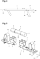
figure 4 is a side view of the conducting bar; -
figure 5 is a perspective view of fuse holding assembly. - In the following detailed description of the figures defined above, the same elements or the elements that are fulfilling identical functions may retain the same references so as to simplify the understanding of the invention.
- As illustrated in
figures 1 to 5 , afuse holding element 1 is configured to cooperate with a conductingend 3 of acylindrical fuse 5 and with a conductingbar 6. Thefuse holding element 1 comprises two holdingbranches 7 extending substantially parallel to acentral plane 9 of thefuse holding element 1, the two holdingbranches 7 facing each other and defining a receivinglocation 11 for said conductingend 3. - The
fuse holding element 1 also comprises a linkingpart 13 on which the two holdingbranches 7 are attached, the linkingpart 13 being provided with a fastener 15 configured to releasably cooperate with acomplementary part 17 of the conductingbar 6. - The
fuse holding element 1 is obtained from a folded metal sheet, the two holdingbranches 7 each corresponding to a folded part of the metal sheet. - The fastener 15 comprises a spring arm 19 configured to cooperate with the
complementary part 17 of the conductingbar 6 so as to maintain thecomplementary part 17 on acontact surface 21 of the linkingpart 13. - The spring arm 19 corresponds to a folded part of said metal sheet. The
contact surface 21 and/or the spring arm 19 is at least partially located between the two holdingbranches 7 according to anextension plane 23 of thecontact surface 21. - The
contact surface 21 extends transversally to thecentral plane 9. The linkingpart 13 is configured so that the spring arm 19 is designed to rotate with respect to the rest of the linkingpart 13 according to a clampingaxis 25 that is transverse to thecentral plane 9. - The spring arm 19 is configured to apply a constraint on the
complementary part 17 of the conductingbar 6 according to a maintainingdirection 27 that is transverse to theextension plane 23 of thecontact surface 21. - The spring arm 19 presents a
protuberance 29 designed to be in contact with the conductingbar 6. The spring arm 19 also comprises alever 31 extending in an inverse direction compared to theprotuberance 29. Thelever 31 is designed to be moved by hand or with the help of a tool to move the spring arm 19 and release the cooperation between the linkingpart 13 and the conductingbar 6. - The linking
part 13 includes apositioning arrangement 33 configured for defining a cooperating position with the conducting bar in a form-fitting manner as shown infigures 1 and5 . - The
positioning arrangement 33 is configured to maintain the conductingbar 6 in the cooperating position with respect to theextension plane 23 of thecontact surface 21. In other words, theposition arrangement 33 is configured to prevent surface displacement of the conductingbar 6 with respect to thecontact surface 21. - The fastener 15 and the
positioning arrangement 33 are configured to define aninsertion direction 35 of the conductingbar 6 for reaching the cooperating position, thepositioning arrangement 33 including a non-return part 37 configured to prevent a withdrawal according to theinsertion direction 35. - In other words, the
insertion direction 35 defines a way for the conductingbar 6 to the cooperating position and the non-return part 37 prevents a withdrawal according to the other way. - The
insertion direction 35 extends parallel to theextension plane 23 of thecontact surface 21. Preferably, theinsertion direction 35 is transverse to the clampingaxis 25. - The non-return part 37 has a blocking surface 39 extending transversally to the
insertion direction 35 and configured to cooperate with acomplementary blocking surface 41 of the conductingbar 6 in the cooperating position. - The
positioning arrangement 33 presents at least onelateral surface 43 extending substantially parallel to thecentral plane 9 and configured to cooperate with a corresponding complementarylateral surface 45 of the conductingbar 6 in the cooperating position. - The at least one
lateral surface 43 is transverse to the blocking surface 39. In particular, the at least onelateral surface 43 is configured to prevent a lateral displacement of the conductingbar 6 with respect to the linkingpart 13 in cooperating position. - The
positioning arrangement 33 comprises a transverse shifting means 47 configured to shift the conductingbar 6 with respect to thecontact surface 21 transversally to the insertingdirection 35 during insertion so as to have the blocking surface 39 cooperating with thecomplementary blocking surface 41 in the cooperating position. - The transverse shifting means 47 is an opening 49 in the linking
part 13 extending transversally to theinsertion direction 35. - The blocking surface 39 and/or the at least one
lateral surface 43 correspond to a contour part of said opening 49. Preferably, said opening 49 is a through opening. - The conducting
bar 6 comprises a complementary positioning arrangement 51 configured to cooperate with thepositioning arrangement 33. Preferably, the complementary positioning arrangement 51 presents a protrusion 53 extending transversally to alongitudinal plane 55 according which the conductingbar 6 is extending. - The
complementary blocking surface 41 and/or the at least one complementarylateral surface 45 are formed on said protrusion 53. Preferably, said protrusion 53 includes a slopedsurface 57 extending from abasis surface 59 of the conductingbar 6 to an apex of the protrusion 53. Thebasis surface 59 of the conductingbar 6 is arranged for cooperating with thecontact surface 21 in the cooperating position. - As illustrated on
figure2 , each of the two holdingbranches 7 presents a profiledcavity 61 adapted to accommodate a part of the conductingend 3 of thecylindrical fuse 5. - The profiled
cavity 61 is engendered by at least one folding of the corresponding holdingbranch 7. Preferably, the two holdingbranches 7 are configured to be in electrical contact with the conductingend 3 of thecylindrical fuse 5. - As illustrated in
figure 1 , apart assembly 63 that comprises thefuse holding element 1 and the conductingbar 6 can be defined. - As illustrated in
figure 5 , afuse holding assembly 65 configured for receiving thecylindrical fuse 5 comprising twofuse holding elements 1. The twocentral planes 9 of thefuse holding elements 1 coincide so that eachfuse holding element 1 is configured to accommodate a conductingend 3 of thecylindrical fuse 5. - The
fuse holding assembly 65 further comprises two conductingbars 6, each being configured to cooperate with a correspondingfuse holding element 1, thefuse holding assembly 65 being configured to put in electrical contact the two conductingbars 6 via thecylindrical fuse 5 when thecylindrical fuse 5 has both conducting ends 3 connected to a correspondingfuse holding element 1. - Each conducting
bar 3 is arranged to be connected to a corresponding external conductor. Preferably, thefuse holding assembly 65 comprises at least oneleaf spring 67 for maintaining said external conductor on the corresponding conductingbar 6. - In particular, the corresponding conducting
bar 6 presents anaccommodating area 69 for theleaf spring 67 and acooperation area 71 on which the external conductor is designed to be maintained. Aterminal block 73, which is schematically represented onfigure 5 , can comprise thefuse holding assembly 65. - The above-described features enable a good position maintaining in the cooperating position that is equivalent to the use of a rivet or equivalent fixing means. They also enable an easy insertion as the sloped surface prevents any blocking during insertion.
- The number of parts is low. The cost of the
fuse holding element 1 and conductingbar 6 is reduced. In addition, the construction is compact. - As goes without saying, the invention is not limited to the sole embodiment described above by way of example, it encompasses all the variants and modifications that are possible to me made, without departing from the scope of the present invention, which is defined by the appended claims.
Claims (10)
- Fuse holding element (1) configured to cooperate with a conducting end (3) of a cylindrical fuse (5) and with a conducting bar (6), the fuse holding element (1) comprising:- two holding branches (7) extending substantially parallel to a central plane (9) of the fuse holding element (1), the two holding branches (7) facing each other and defining a receiving location (11) for said conducting end (3),- a linking part (13) on which the two holding branches (7) are attached, the linking part (13) being provided with a fastener (15) configured to releasably cooperate with a complementary part (17) of the conducting bar (6)wherein the linking part (13) includes a positioning arrangement (33) configured for defining a cooperating position with the conducting bar (6) in a form-fitting manner, characterized in that the fastener (15) and the positioning arrangement (33) are being configured to define an insertion direction (35) of the conducting bar (6) for reaching the cooperating position, the positioning arrangement (33) including a non-return part (37) configured to prevent a withdrawal according to the insertion direction (35).
- Fuse holding element (1) according to claim 1, wherein the fastener (15) comprises a spring arm (19) configured to cooperate with the complementary part (17) of the conducting bar (6) so as to maintain the complementary part (17) on a contact surface (21) of the linking part (13).
- Fuse holding element (1) according to claim 2, wherein the contact surface (21) extends transversally to the central plane (9).
- Fuse holding element (1) according to one of the claims 1 to 3, wherein the non-return part (37) presents a blocking surface (39) extending transversally to the insertion direction (35) and configured to cooperate with a complementary blocking surface (41) of the conducting bar (6) in the cooperating position.
- Fuse holding element (1) according to claim 4, wherein the positioning arrangement (33) comprises a transverse shifting means (47) configured to shift the conducting bar (6) with respect to the contact surface (21) transversally to the inserting direction (35) during insertion so as to have the blocking surface (39) cooperating with the complementary blocking surface (41) in the cooperating position.
- Fuse holding element (1) according to claim 5, wherein the transverse shifting means (47) is an opening (49) in the linking part (13) extending transversally to the insertion direction (35).
- Fuse holding element (1) according to one of the claims 1 to 6, wherein each of the two holding branches (7) presents a profiled cavity (61) adapted to accommodate a part of the conducting end (3) of the cylindrical fuse (5).
- Fuse holding assembly (65) configured for receiving the cylindrical fuse (5) comprising two fuse holding elements (1) according one of the claims 1 to 7, wherein the two central planes (9) of the fuse holding elements (1) coincide so that each fuse holding element (1) is configured to accommodate a conducting end (3) of the cylindrical fuse (5).
- Fuse holding assembly (65) according to claim 8, further comprising two conducting bars (6), each being configured to cooperate with a corresponding fuse holding element (1), the fuse holding assembly (65) being configured to put in electrical contact the two conducting bars (6) via the cylindrical fuse (5) when the cylindrical fuse (5) has both conducting ends (3) connected to a corresponding fuse holding element (1).
- Terminal block (73) comprising a fuse holding assembly (65) according to one of the claims 8 or 9.
Priority Applications (3)
| Application Number | Priority Date | Filing Date | Title |
|---|---|---|---|
| EP20315161.8A EP3896715B1 (en) | 2020-04-14 | 2020-04-14 | Fuse holding element configured to releasably cooperate with a conducting bar |
| US17/227,948 US11295920B2 (en) | 2020-04-14 | 2021-04-12 | Fuse holding element configured to releasibly cooperate with a conducting bar |
| CN202110388531.2A CN113539761B (en) | 2020-04-14 | 2021-04-12 | Fuse holding element configured to releasably mate with a conductive strip |
Applications Claiming Priority (1)
| Application Number | Priority Date | Filing Date | Title |
|---|---|---|---|
| EP20315161.8A EP3896715B1 (en) | 2020-04-14 | 2020-04-14 | Fuse holding element configured to releasably cooperate with a conducting bar |
Publications (2)
| Publication Number | Publication Date |
|---|---|
| EP3896715A1 EP3896715A1 (en) | 2021-10-20 |
| EP3896715B1 true EP3896715B1 (en) | 2024-04-24 |
Family
ID=70861414
Family Applications (1)
| Application Number | Title | Priority Date | Filing Date |
|---|---|---|---|
| EP20315161.8A Active EP3896715B1 (en) | 2020-04-14 | 2020-04-14 | Fuse holding element configured to releasably cooperate with a conducting bar |
Country Status (3)
| Country | Link |
|---|---|
| US (1) | US11295920B2 (en) |
| EP (1) | EP3896715B1 (en) |
| CN (1) | CN113539761B (en) |
Families Citing this family (1)
| Publication number | Priority date | Publication date | Assignee | Title |
|---|---|---|---|---|
| USD993930S1 (en) * | 2021-01-21 | 2023-08-01 | Chs Healthcare Ventures Inc | Fuse clip |
Family Cites Families (13)
| Publication number | Priority date | Publication date | Assignee | Title |
|---|---|---|---|---|
| GB2092398B (en) * | 1981-01-29 | 1984-10-31 | Bicc Ltd | An electrically conductive plug pin |
| US4432594A (en) * | 1981-10-01 | 1984-02-21 | Littelfuse, Inc. | Clip-together interconnection busing clip for multiple fuse holder arrays |
| US4472018A (en) * | 1983-02-16 | 1984-09-18 | Mcgraw-Edison Company | Fuse clip with enclosed wire connection |
| GB2227379B (en) * | 1988-12-21 | 1993-07-14 | Daiichi Denso Buhin | Clamp type connection device |
| CA2040286C (en) * | 1990-04-25 | 1996-04-16 | Tsunesuke Takano | Connector attachment component |
| US6031446A (en) * | 1999-03-09 | 2000-02-29 | Eaton Corporation | Combination fuse clip and line terminal connection device |
| US6790104B2 (en) * | 2002-07-26 | 2004-09-14 | Antaya Technologies Corporation | Electrical terminal |
| US20070093089A1 (en) * | 2005-10-20 | 2007-04-26 | Ford Douglas K | Relay-fuse system and method thereof |
| JP2012109039A (en) * | 2010-11-15 | 2012-06-07 | Yazaki Corp | Terminal connection structure |
| DE102015216632A1 (en) * | 2015-08-31 | 2017-03-02 | Te Connectivity Germany Gmbh | Arrangement for establishing an electrical connection between a flat contact and a high-current conductor |
| CN109891675A (en) * | 2016-09-29 | 2019-06-14 | 泰科电子服务有限责任公司 | There are two the electric connection systems of connection branch for tool |
| US10381183B2 (en) * | 2016-11-22 | 2019-08-13 | Ilsco Corporation | Power distribution clip assembly |
| US9991611B1 (en) * | 2017-09-12 | 2018-06-05 | Siemens Industry, Inc. | Wire nut (lug) fuse holder combination |
-
2020
- 2020-04-14 EP EP20315161.8A patent/EP3896715B1/en active Active
-
2021
- 2021-04-12 CN CN202110388531.2A patent/CN113539761B/en active Active
- 2021-04-12 US US17/227,948 patent/US11295920B2/en active Active
Also Published As
| Publication number | Publication date |
|---|---|
| EP3896715A1 (en) | 2021-10-20 |
| US20210319968A1 (en) | 2021-10-14 |
| US11295920B2 (en) | 2022-04-05 |
| CN113539761B (en) | 2024-06-04 |
| CN113539761A (en) | 2021-10-22 |
Similar Documents
| Publication | Publication Date | Title |
|---|---|---|
| US7988505B2 (en) | Vibration-damping contact element | |
| US6872103B1 (en) | Bushing contact | |
| JP5756661B2 (en) | Electrical junction box | |
| KR20150116846A (en) | Spring-loaded clamping connection and conductor terminal | |
| US10434968B2 (en) | Connector component for securing an airbag module to a steering wheel, positioning sleeve for the connector component, set comprising such a connector component and a positioning sleeve, steering wheel, airbag module, steering wheel assembly, and method for producing same | |
| KR20050007446A (en) | Wiper device comprising a flat wiper blade and wiper arm | |
| US20190237904A1 (en) | Electrical plug connection | |
| JP2016507145A (en) | Spring force tightening element and connecting terminal | |
| EP3896715A1 (en) | Fuse holding element configured to releasably cooperate with a conducting bar | |
| JP7681678B2 (en) | Device for connecting a wiper blade to a wiper arm, assembly and wiper system | |
| US10892578B2 (en) | Conductor terminal | |
| EP3425739A1 (en) | Assembly for switchboard terminal blocks comprising conductor element and resilient means for unidirectionally retaining electric wires | |
| CN113097771A (en) | Holding frame for a plug connector | |
| JP4291341B2 (en) | Connected device | |
| EP3480907A1 (en) | Electrical connection box provided with disconnection/connection structure of dark current circuit | |
| US20240413549A1 (en) | Conductor terminal | |
| PL367049A1 (en) | Electrical connector | |
| CN111863565B (en) | Block for vehicle | |
| JP7835777B2 (en) | Actuating elements, connection assemblies, connection terminals, electronic equipment, and methods for mounting connection terminals. | |
| JPH10201047A (en) | Block structure of electrical junction box | |
| EP3940880A1 (en) | Battery terminal | |
| KR100325358B1 (en) | Battery fixing structure for automobiles | |
| EP3202622A1 (en) | A load carrier foot | |
| JP7845947B2 (en) | Electrical component housing box | |
| CN224021061U (en) | Connection terminal for connecting electrical conductors |
Legal Events
| Date | Code | Title | Description |
|---|---|---|---|
| STAA | Information on the status of an ep patent application or granted ep patent |
Free format text: STATUS: UNKNOWN |
|
| PUAI | Public reference made under article 153(3) epc to a published international application that has entered the european phase |
Free format text: ORIGINAL CODE: 0009012 |
|
| STAA | Information on the status of an ep patent application or granted ep patent |
Free format text: STATUS: THE APPLICATION HAS BEEN PUBLISHED |
|
| AK | Designated contracting states |
Kind code of ref document: A1 Designated state(s): AL AT BE BG CH CY CZ DE DK EE ES FI FR GB GR HR HU IE IS IT LI LT LU LV MC MK MT NL NO PL PT RO RS SE SI SK SM TR |
|
| B565 | Issuance of search results under rule 164(2) epc |
Effective date: 20210202 |
|
| STAA | Information on the status of an ep patent application or granted ep patent |
Free format text: STATUS: REQUEST FOR EXAMINATION WAS MADE |
|
| 17P | Request for examination filed |
Effective date: 20220324 |
|
| RBV | Designated contracting states (corrected) |
Designated state(s): AL AT BE BG CH CY CZ DE DK EE ES FI FR GB GR HR HU IE IS IT LI LT LU LV MC MK MT NL NO PL PT RO RS SE SI SK SM TR |
|
| GRAP | Despatch of communication of intention to grant a patent |
Free format text: ORIGINAL CODE: EPIDOSNIGR1 |
|
| STAA | Information on the status of an ep patent application or granted ep patent |
Free format text: STATUS: GRANT OF PATENT IS INTENDED |
|
| RIC1 | Information provided on ipc code assigned before grant |
Ipc: H01R 33/02 20060101ALN20231102BHEP Ipc: H01R 13/11 20060101ALN20231102BHEP Ipc: H01H 85/157 20060101ALN20231102BHEP Ipc: H01H 85/045 20060101ALN20231102BHEP Ipc: H01H 85/041 20060101ALN20231102BHEP Ipc: H01H 85/20 20060101AFI20231102BHEP |
|
| INTG | Intention to grant announced |
Effective date: 20231124 |
|
| GRAS | Grant fee paid |
Free format text: ORIGINAL CODE: EPIDOSNIGR3 |
|
| GRAA | (expected) grant |
Free format text: ORIGINAL CODE: 0009210 |
|
| STAA | Information on the status of an ep patent application or granted ep patent |
Free format text: STATUS: THE PATENT HAS BEEN GRANTED |
|
| AK | Designated contracting states |
Kind code of ref document: B1 Designated state(s): AL AT BE BG CH CY CZ DE DK EE ES FI FR GB GR HR HU IE IS IT LI LT LU LV MC MK MT NL NO PL PT RO RS SE SI SK SM TR |
|
| REG | Reference to a national code |
Ref country code: GB Ref legal event code: FG4D |
|
| REG | Reference to a national code |
Ref country code: CH Ref legal event code: EP |
|
| REG | Reference to a national code |
Ref country code: DE Ref legal event code: R096 Ref document number: 602020029493 Country of ref document: DE |
|
| REG | Reference to a national code |
Ref country code: IE Ref legal event code: FG4D |
|
| REG | Reference to a national code |
Ref country code: LT Ref legal event code: MG9D |
|
| REG | Reference to a national code |
Ref country code: NL Ref legal event code: MP Effective date: 20240424 |
|
| REG | Reference to a national code |
Ref country code: AT Ref legal event code: MK05 Ref document number: 1680564 Country of ref document: AT Kind code of ref document: T Effective date: 20240424 |
|
| PG25 | Lapsed in a contracting state [announced via postgrant information from national office to epo] |
Ref country code: NL Free format text: LAPSE BECAUSE OF FAILURE TO SUBMIT A TRANSLATION OF THE DESCRIPTION OR TO PAY THE FEE WITHIN THE PRESCRIBED TIME-LIMIT Effective date: 20240424 |
|
| PG25 | Lapsed in a contracting state [announced via postgrant information from national office to epo] |
Ref country code: NL Free format text: LAPSE BECAUSE OF FAILURE TO SUBMIT A TRANSLATION OF THE DESCRIPTION OR TO PAY THE FEE WITHIN THE PRESCRIBED TIME-LIMIT Effective date: 20240424 |
|
| PG25 | Lapsed in a contracting state [announced via postgrant information from national office to epo] |
Ref country code: IS Free format text: LAPSE BECAUSE OF FAILURE TO SUBMIT A TRANSLATION OF THE DESCRIPTION OR TO PAY THE FEE WITHIN THE PRESCRIBED TIME-LIMIT Effective date: 20240824 |
|
| PG25 | Lapsed in a contracting state [announced via postgrant information from national office to epo] |
Ref country code: BG Free format text: LAPSE BECAUSE OF FAILURE TO SUBMIT A TRANSLATION OF THE DESCRIPTION OR TO PAY THE FEE WITHIN THE PRESCRIBED TIME-LIMIT Effective date: 20240424 |
|
| PG25 | Lapsed in a contracting state [announced via postgrant information from national office to epo] |
Ref country code: HR Free format text: LAPSE BECAUSE OF FAILURE TO SUBMIT A TRANSLATION OF THE DESCRIPTION OR TO PAY THE FEE WITHIN THE PRESCRIBED TIME-LIMIT Effective date: 20240424 Ref country code: FI Free format text: LAPSE BECAUSE OF FAILURE TO SUBMIT A TRANSLATION OF THE DESCRIPTION OR TO PAY THE FEE WITHIN THE PRESCRIBED TIME-LIMIT Effective date: 20240424 |
|
| PG25 | Lapsed in a contracting state [announced via postgrant information from national office to epo] |
Ref country code: GR Free format text: LAPSE BECAUSE OF FAILURE TO SUBMIT A TRANSLATION OF THE DESCRIPTION OR TO PAY THE FEE WITHIN THE PRESCRIBED TIME-LIMIT Effective date: 20240725 |
|
| PG25 | Lapsed in a contracting state [announced via postgrant information from national office to epo] |
Ref country code: PT Free format text: LAPSE BECAUSE OF FAILURE TO SUBMIT A TRANSLATION OF THE DESCRIPTION OR TO PAY THE FEE WITHIN THE PRESCRIBED TIME-LIMIT Effective date: 20240826 |
|
| PG25 | Lapsed in a contracting state [announced via postgrant information from national office to epo] |
Ref country code: ES Free format text: LAPSE BECAUSE OF FAILURE TO SUBMIT A TRANSLATION OF THE DESCRIPTION OR TO PAY THE FEE WITHIN THE PRESCRIBED TIME-LIMIT Effective date: 20240424 |
|
| PG25 | Lapsed in a contracting state [announced via postgrant information from national office to epo] |
Ref country code: AT Free format text: LAPSE BECAUSE OF FAILURE TO SUBMIT A TRANSLATION OF THE DESCRIPTION OR TO PAY THE FEE WITHIN THE PRESCRIBED TIME-LIMIT Effective date: 20240424 |
|
| PG25 | Lapsed in a contracting state [announced via postgrant information from national office to epo] |
Ref country code: PL Free format text: LAPSE BECAUSE OF FAILURE TO SUBMIT A TRANSLATION OF THE DESCRIPTION OR TO PAY THE FEE WITHIN THE PRESCRIBED TIME-LIMIT Effective date: 20240424 |
|
| PG25 | Lapsed in a contracting state [announced via postgrant information from national office to epo] |
Ref country code: LV Free format text: LAPSE BECAUSE OF FAILURE TO SUBMIT A TRANSLATION OF THE DESCRIPTION OR TO PAY THE FEE WITHIN THE PRESCRIBED TIME-LIMIT Effective date: 20240424 |
|
| PG25 | Lapsed in a contracting state [announced via postgrant information from national office to epo] |
Ref country code: PT Free format text: LAPSE BECAUSE OF FAILURE TO SUBMIT A TRANSLATION OF THE DESCRIPTION OR TO PAY THE FEE WITHIN THE PRESCRIBED TIME-LIMIT Effective date: 20240826 Ref country code: PL Free format text: LAPSE BECAUSE OF FAILURE TO SUBMIT A TRANSLATION OF THE DESCRIPTION OR TO PAY THE FEE WITHIN THE PRESCRIBED TIME-LIMIT Effective date: 20240424 Ref country code: NO Free format text: LAPSE BECAUSE OF FAILURE TO SUBMIT A TRANSLATION OF THE DESCRIPTION OR TO PAY THE FEE WITHIN THE PRESCRIBED TIME-LIMIT Effective date: 20240724 Ref country code: LV Free format text: LAPSE BECAUSE OF FAILURE TO SUBMIT A TRANSLATION OF THE DESCRIPTION OR TO PAY THE FEE WITHIN THE PRESCRIBED TIME-LIMIT Effective date: 20240424 Ref country code: IS Free format text: LAPSE BECAUSE OF FAILURE TO SUBMIT A TRANSLATION OF THE DESCRIPTION OR TO PAY THE FEE WITHIN THE PRESCRIBED TIME-LIMIT Effective date: 20240824 Ref country code: HR Free format text: LAPSE BECAUSE OF FAILURE TO SUBMIT A TRANSLATION OF THE DESCRIPTION OR TO PAY THE FEE WITHIN THE PRESCRIBED TIME-LIMIT Effective date: 20240424 Ref country code: GR Free format text: LAPSE BECAUSE OF FAILURE TO SUBMIT A TRANSLATION OF THE DESCRIPTION OR TO PAY THE FEE WITHIN THE PRESCRIBED TIME-LIMIT Effective date: 20240725 Ref country code: FI Free format text: LAPSE BECAUSE OF FAILURE TO SUBMIT A TRANSLATION OF THE DESCRIPTION OR TO PAY THE FEE WITHIN THE PRESCRIBED TIME-LIMIT Effective date: 20240424 Ref country code: ES Free format text: LAPSE BECAUSE OF FAILURE TO SUBMIT A TRANSLATION OF THE DESCRIPTION OR TO PAY THE FEE WITHIN THE PRESCRIBED TIME-LIMIT Effective date: 20240424 Ref country code: BG Free format text: LAPSE BECAUSE OF FAILURE TO SUBMIT A TRANSLATION OF THE DESCRIPTION OR TO PAY THE FEE WITHIN THE PRESCRIBED TIME-LIMIT Effective date: 20240424 Ref country code: AT Free format text: LAPSE BECAUSE OF FAILURE TO SUBMIT A TRANSLATION OF THE DESCRIPTION OR TO PAY THE FEE WITHIN THE PRESCRIBED TIME-LIMIT Effective date: 20240424 Ref country code: RS Free format text: LAPSE BECAUSE OF FAILURE TO SUBMIT A TRANSLATION OF THE DESCRIPTION OR TO PAY THE FEE WITHIN THE PRESCRIBED TIME-LIMIT Effective date: 20240724 |
|
| REG | Reference to a national code |
Ref country code: DE Ref legal event code: R081 Ref document number: 602020029493 Country of ref document: DE Owner name: TE CONNECTIVITY SOLUTIONS GMBH, CH Free format text: FORMER OWNER: TYCO ELECTRONICS FRANCE SAS, PONTOISE, FR |
|
| REG | Reference to a national code |
Ref country code: GB Ref legal event code: 732E Free format text: REGISTERED BETWEEN 20241114 AND 20241120 |
|
| PG25 | Lapsed in a contracting state [announced via postgrant information from national office to epo] |
Ref country code: DK Free format text: LAPSE BECAUSE OF FAILURE TO SUBMIT A TRANSLATION OF THE DESCRIPTION OR TO PAY THE FEE WITHIN THE PRESCRIBED TIME-LIMIT Effective date: 20240424 |
|
| PG25 | Lapsed in a contracting state [announced via postgrant information from national office to epo] |
Ref country code: EE Free format text: LAPSE BECAUSE OF FAILURE TO SUBMIT A TRANSLATION OF THE DESCRIPTION OR TO PAY THE FEE WITHIN THE PRESCRIBED TIME-LIMIT Effective date: 20240424 |
|
| PG25 | Lapsed in a contracting state [announced via postgrant information from national office to epo] |
Ref country code: CZ Free format text: LAPSE BECAUSE OF FAILURE TO SUBMIT A TRANSLATION OF THE DESCRIPTION OR TO PAY THE FEE WITHIN THE PRESCRIBED TIME-LIMIT Effective date: 20240424 |
|
| PG25 | Lapsed in a contracting state [announced via postgrant information from national office to epo] |
Ref country code: SK Free format text: LAPSE BECAUSE OF FAILURE TO SUBMIT A TRANSLATION OF THE DESCRIPTION OR TO PAY THE FEE WITHIN THE PRESCRIBED TIME-LIMIT Effective date: 20240424 Ref country code: RO Free format text: LAPSE BECAUSE OF FAILURE TO SUBMIT A TRANSLATION OF THE DESCRIPTION OR TO PAY THE FEE WITHIN THE PRESCRIBED TIME-LIMIT Effective date: 20240424 |
|
| REG | Reference to a national code |
Ref country code: DE Ref legal event code: R097 Ref document number: 602020029493 Country of ref document: DE |
|
| PG25 | Lapsed in a contracting state [announced via postgrant information from national office to epo] |
Ref country code: SM Free format text: LAPSE BECAUSE OF FAILURE TO SUBMIT A TRANSLATION OF THE DESCRIPTION OR TO PAY THE FEE WITHIN THE PRESCRIBED TIME-LIMIT Effective date: 20240424 |
|
| PG25 | Lapsed in a contracting state [announced via postgrant information from national office to epo] |
Ref country code: SM Free format text: LAPSE BECAUSE OF FAILURE TO SUBMIT A TRANSLATION OF THE DESCRIPTION OR TO PAY THE FEE WITHIN THE PRESCRIBED TIME-LIMIT Effective date: 20240424 Ref country code: SK Free format text: LAPSE BECAUSE OF FAILURE TO SUBMIT A TRANSLATION OF THE DESCRIPTION OR TO PAY THE FEE WITHIN THE PRESCRIBED TIME-LIMIT Effective date: 20240424 Ref country code: RO Free format text: LAPSE BECAUSE OF FAILURE TO SUBMIT A TRANSLATION OF THE DESCRIPTION OR TO PAY THE FEE WITHIN THE PRESCRIBED TIME-LIMIT Effective date: 20240424 Ref country code: EE Free format text: LAPSE BECAUSE OF FAILURE TO SUBMIT A TRANSLATION OF THE DESCRIPTION OR TO PAY THE FEE WITHIN THE PRESCRIBED TIME-LIMIT Effective date: 20240424 Ref country code: DK Free format text: LAPSE BECAUSE OF FAILURE TO SUBMIT A TRANSLATION OF THE DESCRIPTION OR TO PAY THE FEE WITHIN THE PRESCRIBED TIME-LIMIT Effective date: 20240424 Ref country code: CZ Free format text: LAPSE BECAUSE OF FAILURE TO SUBMIT A TRANSLATION OF THE DESCRIPTION OR TO PAY THE FEE WITHIN THE PRESCRIBED TIME-LIMIT Effective date: 20240424 |
|
| PLBE | No opposition filed within time limit |
Free format text: ORIGINAL CODE: 0009261 |
|
| STAA | Information on the status of an ep patent application or granted ep patent |
Free format text: STATUS: NO OPPOSITION FILED WITHIN TIME LIMIT |
|
| 26N | No opposition filed |
Effective date: 20250127 |
|
| PG25 | Lapsed in a contracting state [announced via postgrant information from national office to epo] |
Ref country code: SI Free format text: LAPSE BECAUSE OF FAILURE TO SUBMIT A TRANSLATION OF THE DESCRIPTION OR TO PAY THE FEE WITHIN THE PRESCRIBED TIME-LIMIT Effective date: 20240424 |
|
| PG25 | Lapsed in a contracting state [announced via postgrant information from national office to epo] |
Ref country code: SE Free format text: LAPSE BECAUSE OF FAILURE TO SUBMIT A TRANSLATION OF THE DESCRIPTION OR TO PAY THE FEE WITHIN THE PRESCRIBED TIME-LIMIT Effective date: 20240424 |
|
| REG | Reference to a national code |
Ref country code: CH Ref legal event code: H13 Free format text: ST27 STATUS EVENT CODE: U-0-0-H10-H13 (AS PROVIDED BY THE NATIONAL OFFICE) Effective date: 20251125 |
|
| PG25 | Lapsed in a contracting state [announced via postgrant information from national office to epo] |
Ref country code: LU Free format text: LAPSE BECAUSE OF NON-PAYMENT OF DUE FEES Effective date: 20250414 |
|
| PG25 | Lapsed in a contracting state [announced via postgrant information from national office to epo] |
Ref country code: MC Free format text: LAPSE BECAUSE OF FAILURE TO SUBMIT A TRANSLATION OF THE DESCRIPTION OR TO PAY THE FEE WITHIN THE PRESCRIBED TIME-LIMIT Effective date: 20240424 |
|
| REG | Reference to a national code |
Ref country code: BE Ref legal event code: MM Effective date: 20250430 |
|
| PG25 | Lapsed in a contracting state [announced via postgrant information from national office to epo] |
Ref country code: BE Free format text: LAPSE BECAUSE OF NON-PAYMENT OF DUE FEES Effective date: 20250430 |
|
| PG25 | Lapsed in a contracting state [announced via postgrant information from national office to epo] |
Ref country code: CH Free format text: LAPSE BECAUSE OF NON-PAYMENT OF DUE FEES Effective date: 20250430 |
|
| PG25 | Lapsed in a contracting state [announced via postgrant information from national office to epo] |
Ref country code: IT Free format text: LAPSE BECAUSE OF FAILURE TO SUBMIT A TRANSLATION OF THE DESCRIPTION OR TO PAY THE FEE WITHIN THE PRESCRIBED TIME-LIMIT Effective date: 20240424 |
|
| PGFP | Annual fee paid to national office [announced via postgrant information from national office to epo] |
Ref country code: GB Payment date: 20260313 Year of fee payment: 7 |
|
| PG25 | Lapsed in a contracting state [announced via postgrant information from national office to epo] |
Ref country code: IE Free format text: LAPSE BECAUSE OF NON-PAYMENT OF DUE FEES Effective date: 20250414 |
|
| PGFP | Annual fee paid to national office [announced via postgrant information from national office to epo] |
Ref country code: FR Payment date: 20260309 Year of fee payment: 7 |
|
| PG25 | Lapsed in a contracting state [announced via postgrant information from national office to epo] |
Ref country code: CY Free format text: LAPSE BECAUSE OF FAILURE TO SUBMIT A TRANSLATION OF THE DESCRIPTION OR TO PAY THE FEE WITHIN THE PRESCRIBED TIME-LIMIT Effective date: 20240424 |
|
| PG25 | Lapsed in a contracting state [announced via postgrant information from national office to epo] |
Ref country code: LT Free format text: LAPSE BECAUSE OF FAILURE TO SUBMIT A TRANSLATION OF THE DESCRIPTION OR TO PAY THE FEE WITHIN THE PRESCRIBED TIME-LIMIT Effective date: 20240424 |
|
| PGFP | Annual fee paid to national office [announced via postgrant information from national office to epo] |
Ref country code: DE Payment date: 20260305 Year of fee payment: 7 |