EP3896713A1 - Direct-current circuit breaker - Google Patents
Direct-current circuit breaker Download PDFInfo
- Publication number
- EP3896713A1 EP3896713A1 EP18942816.2A EP18942816A EP3896713A1 EP 3896713 A1 EP3896713 A1 EP 3896713A1 EP 18942816 A EP18942816 A EP 18942816A EP 3896713 A1 EP3896713 A1 EP 3896713A1
- Authority
- EP
- European Patent Office
- Prior art keywords
- circuit breaker
- mechanical
- closing device
- unitary
- support plate
- Prior art date
- Legal status (The legal status is an assumption and is not a legal conclusion. Google has not performed a legal analysis and makes no representation as to the accuracy of the status listed.)
- Granted
Links
Images





Classifications
-
- H—ELECTRICITY
- H01—ELECTRIC ELEMENTS
- H01H—ELECTRIC SWITCHES; RELAYS; SELECTORS; EMERGENCY PROTECTIVE DEVICES
- H01H33/00—High-tension or heavy-current switches with arc-extinguishing or arc-preventing means
- H01H33/02—Details
- H01H33/59—Circuit arrangements not adapted to a particular application of the switch and not otherwise provided for, e.g. for ensuring operation of the switch at a predetermined point in the AC cycle
- H01H33/596—Circuit arrangements not adapted to a particular application of the switch and not otherwise provided for, e.g. for ensuring operation of the switch at a predetermined point in the AC cycle for interrupting DC
-
- H—ELECTRICITY
- H01—ELECTRIC ELEMENTS
- H01H—ELECTRIC SWITCHES; RELAYS; SELECTORS; EMERGENCY PROTECTIVE DEVICES
- H01H33/00—High-tension or heavy-current switches with arc-extinguishing or arc-preventing means
- H01H33/008—Pedestal mounted switch gear combinations
-
- H—ELECTRICITY
- H01—ELECTRIC ELEMENTS
- H01H—ELECTRIC SWITCHES; RELAYS; SELECTORS; EMERGENCY PROTECTIVE DEVICES
- H01H33/00—High-tension or heavy-current switches with arc-extinguishing or arc-preventing means
- H01H33/02—Details
- H01H33/28—Power arrangements internal to the switch for operating the driving mechanism
- H01H33/285—Power arrangements internal to the switch for operating the driving mechanism using electro-dynamic repulsion
-
- H—ELECTRICITY
- H01—ELECTRIC ELEMENTS
- H01T—SPARK GAPS; OVERVOLTAGE ARRESTERS USING SPARK GAPS; SPARKING PLUGS; CORONA DEVICES; GENERATING IONS TO BE INTRODUCED INTO NON-ENCLOSED GASES
- H01T2/00—Spark gaps comprising auxiliary triggering means
- H01T2/02—Spark gaps comprising auxiliary triggering means comprising a trigger electrode or an auxiliary spark gap
-
- H—ELECTRICITY
- H01—ELECTRIC ELEMENTS
- H01T—SPARK GAPS; OVERVOLTAGE ARRESTERS USING SPARK GAPS; SPARKING PLUGS; CORONA DEVICES; GENERATING IONS TO BE INTRODUCED INTO NON-ENCLOSED GASES
- H01T4/00—Overvoltage arresters using spark gaps
- H01T4/10—Overvoltage arresters using spark gaps having a single gap or a plurality of gaps in parallel
- H01T4/12—Overvoltage arresters using spark gaps having a single gap or a plurality of gaps in parallel hermetically sealed
-
- H—ELECTRICITY
- H01—ELECTRIC ELEMENTS
- H01H—ELECTRIC SWITCHES; RELAYS; SELECTORS; EMERGENCY PROTECTIVE DEVICES
- H01H9/00—Details of switching devices, not covered by groups H01H1/00 - H01H7/00
- H01H9/54—Circuit arrangements not adapted to a particular application of the switching device and for which no provision exists elsewhere
- H01H9/541—Contacts shunted by semiconductor devices
- H01H9/542—Contacts shunted by static switch means
- H01H2009/543—Contacts shunted by static switch means third parallel branch comprising an energy absorber, e.g. MOV, PTC, Zener
-
- H—ELECTRICITY
- H01—ELECTRIC ELEMENTS
- H01H—ELECTRIC SWITCHES; RELAYS; SELECTORS; EMERGENCY PROTECTIVE DEVICES
- H01H33/00—High-tension or heavy-current switches with arc-extinguishing or arc-preventing means
- H01H33/60—Switches wherein the means for extinguishing or preventing the arc do not include separate means for obtaining or increasing flow of arc-extinguishing fluid
- H01H33/66—Vacuum switches
- H01H33/666—Operating arrangements
- H01H2033/6665—Details concerning the mounting or supporting of the individual vacuum bottles
-
- H—ELECTRICITY
- H01—ELECTRIC ELEMENTS
- H01H—ELECTRIC SWITCHES; RELAYS; SELECTORS; EMERGENCY PROTECTIVE DEVICES
- H01H33/00—High-tension or heavy-current switches with arc-extinguishing or arc-preventing means
- H01H33/02—Details
- H01H33/04—Means for extinguishing or preventing arc between current-carrying parts
- H01H33/14—Multiple main contacts for the purpose of dividing the current through, or potential drop along, the arc
-
- H—ELECTRICITY
- H01—ELECTRIC ELEMENTS
- H01H—ELECTRIC SWITCHES; RELAYS; SELECTORS; EMERGENCY PROTECTIVE DEVICES
- H01H33/00—High-tension or heavy-current switches with arc-extinguishing or arc-preventing means
- H01H33/60—Switches wherein the means for extinguishing or preventing the arc do not include separate means for obtaining or increasing flow of arc-extinguishing fluid
- H01H33/66—Vacuum switches
- H01H33/666—Operating arrangements
Definitions
- Embodiments of the present invention relate to a direct-current circuit breaker.
- Direct-current power transmission has higher power transmission efficiency than alternating-current power transmission.
- the introduction cost of equipment is higher for direct-current power transmission.
- power transmission efficiency of direct-current power transmission is predominantly high, and thus, when evaluation is performed for equipment costs together with operating costs, direct-current power transmission is generally lower in cost. For this reason, direct-current power transmission is used for power transmission between two bases across the sea, for example.
- a device capable of quickly breaking an accident point from a sound system is required.
- a mechanical contact type circuit breaker is used in an alternating-current system.
- the mechanical contact type circuit breaker breaks an accident current by opening contacts at a current zero point generated by an alternating current and blowing an insulation medium to an arc current between the contacts.
- the current zero point does not occur in the accident current, and thus it is difficult to quickly break the accident current with the mechanical contact type circuit breaker of the related art.
- a semiconductor circuit breaker capable of breaking a direct current independently, a semiconductor circuit breaker using a plurality of self-excited semiconductor elements having a self-extinguishing ability, such as an insulated gate bipolar transistor (IGBT), has been proposed.
- IGBT insulated gate bipolar transistor
- a contact-opening command is given to the mechanical contact type disconnector at the same time at which the auxiliary semiconductor circuit breaker enters a circuit-broken state.
- the auxiliary semiconductor circuit breaker is in a circuit-broken state in this way, an accident current flowing along a path between the mechanical contact type disconnector and the auxiliary semiconductor circuit breaker is commutated to the other semiconductor circuit breaker described above.
- the other semiconductor circuit breaker described above is circuit-broken to complete the breaking of the accident current.
- a conduction loss during normal power transmission is only a conduction loss of the auxiliary semiconductor circuit breaker, and thus the conduction loss can be reduced as compared with the configuration in which the normal energization path is constituted by only the semiconductor circuit breaker capable of breaking the direct current independently as described above.
- the hybrid circuit breaker since an energization loss of the auxiliary semiconductor circuit breaker still occurs, the hybrid circuit breaker has a larger conduction loss than the mechanical contact type circuit breaker of the related art in which the normal energization path is constituted by only the mechanical contacts.
- a direct-current circuit breaker in which a mechanical contact type circuit breaker is connected in parallel to a circuit in which a semiconductor circuit breaker and a commutation circuit constituted by a half-bridge circuit are connected in series has been proposed.
- the mechanical contact type disconnector is in a conducted state, and the semiconductor circuit breaker and the commutation circuit are in a circuit-broken state. Therefore, a transmission current at the time of normal power transmission flows through only the mechanical contact type disconnector.
- a contact-opening command is given to the mechanical contact type circuit breaker
- the semiconductor circuit breaker enters a conducted state
- a commutation command is given to the commutation circuit.
- the commutation circuit causes a current to flow in a direction opposite to the accident current flowing in the mechanical contact type circuit breaker to generate a zero point in the current of the mechanical contact type circuit breaker
- the contacts of the mechanical contact type circuit breaker are opened, and thus the accident current is commutated from the mechanical contact type circuit breaker to the semiconductor circuit breaker and the commutation circuit.
- the semiconductor breaker is circuit-broken to complete the breaking of the accident current.
- An object of the present invention is to provide a direct-current circuit breaker capable of shortening the current breaking time and suppressing the equipment cost.
- a direct-current circuit breaker includes a mechanical circuit breaking section, a surge absorber, and a commutation device.
- the mechanical circuit breaking section has at least one mechanical circuit breaking unit and an insulation column.
- the at least one mechanical circuit breaking unit has at least one unitary circuit breaker.
- the insulation column supports the at least one mechanical circuit breaking unit.
- Each of the at least one unitary circuit breaker has a mechanical contact portion, a sealed container, an operation rod, and an operation mechanism.
- the mechanical contact portion has a fixed contact and a movable contact.
- the mechanical contact portion is electrically insulated from the ground.
- the sealed container encloses the mechanical contact portion and is filled with an insulation gas.
- the sealed container is electrically insulated from the ground.
- the operation rod is connected to the movable contact.
- the operation rod extends from the inside of the sealed container to the outside thereof.
- the operation mechanism is connected to the operation rod.
- the operation mechanism is configured to bring the movable contact in and out of contact with the fixed contact.
- the operation mechanism is provided to have the same potential as the movable contact.
- the at least one unitary circuit breaker has a first unitary circuit breaker and a second unitary circuit breaker.
- the first unitary circuit breaker and the second unitary circuit breaker are disposed such that the respective operation rods operate on the same straight line by the operation mechanisms, and the operation directions of the operation rods by the operation mechanisms are opposite to each other.
- the first unitary circuit breaker and the second unitary circuit breaker are disposed such that the respective operation mechanisms face each other.
- All of the at least one unitary circuit breaker are connected in series to form a mechanical contact module. Both ends of the mechanical contact module are connected to a direct-current power transmission system.
- the surge absorber is connected in parallel to the mechanical contact module.
- the commutation device has a commutation circuit.
- the commutation circuit is formed by a reactor, a capacitor, and a closing device being connected in series.
- the commutation circuit is connected in parallel to the mechanical contact module.
- the closing device is a high-speed closing device.
- FIG. 1 is a perspective view showing a direct-current circuit breaker according to a first embodiment.
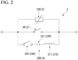
- FIG. 2 is a circuit diagram showing the direct-current circuit breaker according to the first embodiment.
- the direct-current circuit breaker 1 includes a mechanical circuit breaking section 2, a surge absorbing section 3, and a commutation device 4.
- the direct-current circuit breaker 1 is installed on a foundation 5 on the ground. An upper surface of the foundation 5 is horizontally formed.
- one horizontal direction is defined as a first direction
- a horizontal direction orthogonal to the first direction is defined as a second direction.
- reference sign X is given to the first direction
- reference sign Y is given to the second direction.
- the mechanical circuit breaking section 2 and the surge absorbing section 3 are disposed side by side in the first direction X.
- a state in which a plurality of objects is disposed side by side in the first direction X is a state in which the objects are disposed to overlap each other when seen in the first direction X.
- the commutation device 4 is disposed side by side in the second direction Y with respect to the mechanical circuit breaking section 2 and the surge absorbing section 3.
- the mechanical circuit breaking section 2 will be described.
- FIG. 3 is a perspective view showing a mechanical circuit breaking section of the first embodiment.
- the mechanical circuit breaking section 2 includes a plurality of (two in the present embodiment) mechanical circuit breaking units 10, a plurality of (four in the present embodiment) insulation columns 60 that supports the mechanical circuit breaking units 10, and a power feeding unit 70 that supplies electric power to the mechanical circuit breaking units 10.
- the plurality of mechanical circuit breaking units 10 is stacked in a plurality of stages in a vertical direction with respect to the insulation columns 60.
- Each of the mechanical circuit breaking units 10 includes a pair of unitary circuit breakers 11 (a first unitary circuit breaker and a second unitary circuit breaker), a power supply section 12, a control section 13, and mechanical breaker support plate 14 on which the pair of unitary circuit breakers 11, the power supply section 12, and the control section 13 are disposed.
- Each of the unitary circuit breakers 11 includes a mechanical contact portion 21 which has a fixed contact 22 and a movable contact 23 (see FIG. 4 ).
- the mechanical contact portion 21 is opened by the movable contact 23 being separated from the fixed contact 22.
- the unitary circuit breaker 11 circuit-breaks an energization path passing through the mechanical contact portion 21 by opening the mechanical contact portion 21.
- the unitary circuit breaker 11 constitutes a vacuum circuit breaker 11A or a gas disconnector 11B.
- the vacuum circuit breaker 11A has a vacuum interrupter 20 in which the mechanical contact portion 21 is disposed in a vacuum insulation cylinder 24 (see FIG. 4 ).
- the gas disconnector 11B has a gas contact in which the mechanical contact portion 21 is disposed in an insulation gas.
- the mechanical contact portion 21 of the vacuum circuit breaker 11A is a contact capable of mechanically breaking a current at a current zero point.
- the current breaking performance of the vacuum circuit breaker 11A is higher than that of the gas disconnector 11B.
- the withstand voltage performance of the gas disconnector 11B is higher than or equivalent to that of the vacuum circuit breaker 11A.
- each mechanical circuit breaking unit 10 it is desirable that the pair of unitary circuit breakers 11 have the same configuration.
- the mechanical circuit breaking unit 10 includes only the vacuum circuit breaker 11A or only the gas disconnector 11B.
- the mechanical circuit breaking unit 10 on an upper stage includes a pair of vacuum circuit breakers 11A.
- the mechanical circuit breaking unit 10 on a lower stage includes a pair of gas disconnectors 11B.
- FIG. 4 is a partial cross-sectional view of a mechanical circuit breaking unit of the first embodiment from the side.
- FIG. 4 shows the mechanical circuit breaking unit 10 provided with the vacuum circuit breaker 11A as the unitary circuit breaker 11.
- the vacuum circuit breaker 11A includes the vacuum interrupter 20 having the mechanical contact portion 21, a sealed container 30 enclosing the vacuum interrupter 20, an energization shaft 34 connected to the fixed contact 22 of the mechanical contact portion 21, an operation rod 35 connected to the movable contact 23 of the mechanical contact portion 21, an operation mechanism 37 connected to the operation rod 35, and a capacitor 39 (see FIG. 3 ) connected in parallel to the mechanical contact portion 21.
- the vacuum interrupter 20 includes the above-mentioned mechanical contact portion 21, the insulation cylinder 24 that encloses the mechanical contact portion 21, and a bellows 25 provided inside the insulation cylinder 24.
- the fixed contact 22 and the movable contact 23 of the mechanical contact portion 21 are provided to be able to come in and out of contact with each other.
- the fixed contact 22 is fixedly disposed with respect to the insulation cylinder 24.
- the movable contact 23 is provided to be displaceable with respect to the insulation cylinder 24.
- a direction in which the fixed contact 22 and the movable contact 23 come in and out of contact with each other is referred to as a contact operation direction.
- the contact operation direction is one horizontal direction and is parallel to the first direction X.
- the insulation cylinder 24 is formed in a cylindrical shape extending along the contact operation direction.
- the insulation cylinder 24 is, for example, a bushing formed of an insulation material.
- the inside of the insulation cylinder 24 is maintained in a vacuum.
- a through hole into which the energization shaft 34 is airtightly inserted is formed in a first end portion of the insulation cylinder 24.
- a through hole into which the operation rod 35 is inserted is formed in a second end portion of the insulation cylinder 24.
- the bellows 25 is disposed inside the insulation cylinder 24 to surround the operation rod 35. One end portion of the bellows 25 is fixed to an outer peripheral surface of the movable contact 23. Another end of the bellows 25 is fixed to the second end portion of the insulation cylinder 24. The bellows 25 maintains the vacuum inside the vacuum interrupter 20 while allowing the movable contact 23 and the operation rod 35 to be displaced with respect to the insulation cylinder 24.
- the sealed container 30 is filled with, for example, sulfur hexafluoride (SF 6 ) gas as the insulation gas.
- the sealed container 30 includes a cylindrical insulation cylinder 31, and a first flange 32 and a second flange 33 which close both end openings of the insulation cylinder 31.
- the insulation cylinder 31 extends along the contact operation direction.
- the insulation cylinder 31 is, for example, a bushing formed of an insulation material.
- the first flange 32 and the second flange 33 are each formed of a metal material.
- the energization shaft 34 is fixed to the first flange 32 of the sealed container 30.
- the energization shaft 34 is disposed to penetrate the insulation cylinder 24 of the vacuum interrupter 20.
- the energization shaft 34 fixedly supports the vacuum interrupter 20 with respect to the sealed container 30.
- the energization shaft 34 fixedly supports the fixed contact 22 in the insulation cylinder 24 of the vacuum interrupter 20.
- the energization shaft 34 is formed of a conductive material such as a metal and is conductively connected to the fixed contact 22.
- the energization shaft 34 conducts the fixed contact 22 and the first flange 32 of the sealed container 30 to each other.
- “conduction” refers to a state in which a plurality of objects are electrically connected to each other and have the same potential. Further, even in a case in which a potential difference occurs due to impedances of the plurality of objects, when the potential difference is small enough to be negligible (for example, several tens of volts or less) compared to the rated voltage of equipment, each potential is treated as the same potential.
- the operation rod 35 extends along the contact operation direction.
- the first end portion of the operation rod 35 is coupled to the movable contact 23 in the insulation cylinder 24 of the vacuum interrupter 20.
- the operation rod 35 is slidably provided in the contact operation direction with respect to the second end portion of the insulation cylinder 24.
- the operation rod 35 extends from the inside of the sealed container 30 to the outside of the sealed container 30 through a through hole 33a provided in the second flange 33.
- the operation rod 35 is provided to be conducted and slidable with respect to the second flange 33 while maintaining airtightness inside the sealed container 30.
- a portion of the operation rod 35 extending from the first end portion to a sliding portion with the second flange 33 is formed of a conductive material such as a metal.
- the operation rod 35 conducts the movable contact 23 and the second flange 33 to each other. At least a part of the operation rod 35 located outside the sealed container 30 is provided with a rod insulation portion 35a that electrically insulates both end portions of the operation rod 35 from each other.
- the operation mechanism 37 is a highly responsive electromagnetic actuator that operates with electric power.
- the electromagnetic actuator is, for example, an electromagnetic repulsion type operation mechanism.
- the electromagnetic repulsion type operation mechanism 37 has a metal plate of a good conductor connected to the second end portion of the operation rod 35 and a coil installed to face the metal plate. At the time of driving, a current is applied to the coil to generate an induced current in a direction opposite to the metal plate, and an electromagnetic repulsive force in a direction opposite to the coil is applied to the metal plate to operate the operation rod 35.
- the operation mechanism 37 is disposed side by side with the second flange 33 in the contact operation direction on the outside of the sealed container 30.
- the operation mechanism 37 is connected to the second flange 33 by a connecting member 38.
- At least a part of the connecting member 38 is formed of an insulation material to electrically insulate both end portions of the connecting member 38 from each other.
- the operation mechanism 37 reciprocates the operation rod 35 in the contact operation direction. As a result, the operation mechanism 37 displaces the movable contact 23 fixedly provided with respect to the operation rod 35 and brings the movable contact 23 in and out of contact with the fixed contact 22.
- the capacitor 39 is disposed outside the sealed container 30.
- the capacitor 39 is electrically and mechanically connected to the first flange 32 and the second flange 33 of the sealed container 30.
- the capacitor 39 includes a high resistance cylinder filled with a dielectric material and electrodes at both ends and has capacitance and resistance.
- the capacitor 39 adjusts a voltage applied to the mechanical contact portion 21 (see FIG. 4 ) during current breaking and in a contact-opened state.
- FIG. 5 is a cross-sectional view showing a gas disconnector according to the first embodiment.
- the gas disconnector 11B differs from the vacuum circuit breaker 11A in that the mechanical contact portion 21 is directly disposed in the sealed container 30. That is, in the gas disconnector 11B, the insulation gas is interposed between the fixed contact 22 and the movable contact 23 in the contact-opened state of the mechanical contact portion 21.
- each mechanical circuit breaking unit 10 the pair of unitary circuit breakers 11 are disposed such that the respective operation rods 35 operate on the same straight line when the mechanical contact portions 21 are opened by the operation mechanisms 37.
- the operation rods 35 of the respective unitary circuit breakers 11 extend on the same straight line.
- the operation rod 35 operates in the first direction X when the mechanical contact portion 21 is opened by the operation mechanism 37.
- the pair of unitary circuit breakers 11 are disposed such that operation directions of the operation rods 35 are opposite to each other when the mechanical contact portions 21 are opened by the operation mechanisms 37.
- each mechanical circuit breaking unit 10 the pair of unitary circuit breakers 11 are disposed such that the respective operation mechanisms 37 are in contact with each other. Further, the unitary circuit breaker 11 of one mechanical circuit breaking unit 10 and the unitary circuit breaker 11 of another mechanical circuit breaking unit 10 are disposed to operate on the same straight line when seen in the vertical direction.
- the power supply section 12 supplies electric power to the operation mechanisms 37 of the pair of unitary circuit breakers 11.
- the power supply section 12 is provided such that a reference potential becomes the same potential as that of the operation mechanism 37.
- the power supply section 12 includes, for example, a capacitor that supplies electric power to the operation mechanism 37 when the mechanical contact portion 21 (see FIG. 4 ) is opened, and a capacitor that supplies electric power to the operation mechanism 37 when the mechanical contact portion 21 is closed, a charging device for each capacitor, and a switching element for holding each capacitor in a charged state and discharging when electric power is supplied (none of these is shown).
- the control section 13 monitors the state of the power supply section 12 and the operation mechanisms 37 of the pair of unitary circuit breakers 11. Further, the control section 13 controls the electric power supply from the power supply section 12 to the operation mechanisms 37 of the pair of unitary circuit breakers 11.
- the mechanical breaker support plate 14 supports the pair of unitary circuit breakers 11, the power supply section 12, and the control section 13 from below.
- the mechanical breaker support plate 14 is formed of a metal material such as an aluminum alloy.
- the mechanical breaker support plate 14 is formed in a rectangular shape in a plan view.
- the mechanical breaker support plate 14 is disposed such that the two sides of the outer edge are parallel to the contact operation direction.
- the mechanical breaker support plate 14 extends in both the first direction X and the second direction Y.
- the mechanical breaker support plates 14 are stacked in a plurality of stages in the vertical direction with respect to the insulation columns 60.
- each mechanical circuit breaking unit 10 at least a part of the sealed container 30 of each of the pair of unitary circuit breakers 11 are disposed outside the mechanical breaker support plate 14 in the horizontal direction.
- the sealed container 30 of each of the pair of unitary circuit breakers 11 are disposed to protrude from the mechanical breaker support plate 14 when seen in the vertical direction.
- only a part of the sealed container 30 is disposed outside the mechanical breaker support plate 14 in the horizontal direction, but the entire sealed container 30 may be disposed outside the mechanical breaker support plate 14 in the horizontal direction. It is sufficient for a portion (for example, the first flange 32) of the sealed container 30 which has the same potential as the fixed contact 22 to be disposed outside the mechanical breaker support plate 14 in the horizontal direction.
- two vertical projection planes including two sides having a twisted positional relationship with the projection line among four sides constituting the mechanical breaker support plate 14 can be defined. It is sufficient for at least a part of the sealed container 30 to be disposed to protrude from a space separated by the two vertical projection planes (a space on a side where the operation mechanism 37 is).
- the mechanical circuit breaking unit 10 further includes a support portion 15 and an in-unit bus bar 16 (a conductive member).
- the support portion 15 is interposed between each of the pair of unitary circuit breakers 11 and the mechanical breaker support plate 14.
- the support portion 15 supports the unitary circuit breakers 11 while floating them from the mechanical breaker support plate 14.
- the support portion 15 includes a pair of first support portions 15A interposed between the second flanges 33 of the unitary circuit breakers 11 and the mechanical breaker support plate 14, and a pair of second support portions 15B interposed between the operation mechanisms 37 of the unitary circuit breakers 11 and the mechanical breaker support plate 14.
- One first support portion 15A includes an insulation portion 15a that cuts off electrical conduction between the second flange 33 and the mechanical breaker support plate 14.
- the second flange 33 of the unitary circuit breaker 11 supported by the one first support portion 15A is electrically insulated from the mechanical breaker support plate 14.
- Another first support portion 15A conducts the second flange 33 of the unitary circuit breaker 11 and the mechanical breaker support plate 14 to each other.
- the second support portion 15B conducts the operation mechanism 37 and the mechanical breaker support plate 14 to each other.
- the in-unit bus bar 16 connects the pair of unitary circuit breakers 11 in series.
- the in-unit bus bar 16 is electrically and mechanically connected to each of the second flanges 33 of the pair of unitary circuit breakers 11.
- the in-unit bus bar 16 extends above the operation mechanism 37 of the pair of unitary circuit breakers 11 to straddle the pair of operation mechanisms 37.
- the in-unit bus bar 16 is formed of a conductive material such as a metal. As a result, the in-unit bus bar 16 conducts the second flanges 33 of the pair of unitary circuit breakers 11 to each other and connects the mechanical contact portions 21 of the pair of unitary circuit breakers 11 in series.
- the insulation columns 60 are formed of, for example, an insulator, a polymer, a fiber reinforced plastic, or the like.
- the insulation columns 60 are erected on the foundation 5.
- the insulation columns 60 extend along the vertical direction.
- Each insulation column 60 supports a corner portion of each of the mechanical breaker support plates 14 stacked in a plurality of stages.
- the insulation columns 60 fixedly support each mechanical circuit breaking unit 10 while electrically insulating the plurality of mechanical circuit breaking units 10 from each other and electrically insulating each mechanical circuit breaking unit 10 from the ground.
- Each insulation column 60 may extend continuously from the lower end to the upper end or may be divided into a plurality of pieces to interpose each mechanical breaker support plate 14 therebetween. The same applies to other insulation columns described later.
- the power feeding unit 70 is installed on the foundation 5 beside the mechanical circuit breaking units 10.
- the power feeding unit 70 is disposed between the mechanical circuit breaking units 10 and the commutation device 4 (see FIG. 1 ).
- the power feeding unit 70 is disposed at a position to overlap the mechanical circuit breaking units 10 when seen in the second direction Y.
- the power feeding unit 70 supplies electric power to the power supply sections 12 of the mechanical circuit breaking units 10 from above the ground.
- the power feeding unit 70 supplies electric power while electrically insulating the ground and the power supply sections 12 from each other and electrically insulating the plurality of mechanical circuit breaking units 10 from each other.
- the power feeding unit 70 includes two-stage insulation transformers which are vertically stacked.
- the lower insulation transformer supplies electric power to the power supply section 12 of the mechanical circuit breaking unit 10 on a lower stage.
- the insulation transformer on an upper stage supplies electric power to the power supply section 12 of the mechanical circuit breaking unit 10 on an upper stage while electrically insulating the power supply section 12 of the mechanical circuit breaking unit 10 on a lower stage and the power supply section 12 of the mechanical circuit breaking unit 10 on an upper stage from each other.
- the power feeding unit 70 may be a laser power feeding device, a device having a power generation function with air passing through an insulation tube, or the like.
- FIG. 6 is a view showing an energization path in the mechanical circuit breaking unit of the first embodiment.
- the first flange 32 and the second flange 33 are conductively connected to each other.
- the second flange 33 of one unitary circuit breaker 11 of the pair of unitary circuit breakers 11 is cut off from direct conduction with the mechanical breaker support plate 14 by the insulation portion 15a of the first support portion 15A. Further, in each unitary circuit breaker 11, the second flange 33 is cut off from direct conduction with the operation mechanism 37 by the rod insulation portion 35a of the operation rod 35 and the connecting member 38. Further, the second flanges 33 of the pair of unitary circuit breakers 11 are conductively connected to each other via the in-unit bus bar 16.
- the current flowing through the pair of unitary circuit breakers 11 flows through the in-unit bus bar 16 from the first flange 32 of one unitary circuit breaker 11 and reaches the first flange 32 of the other unitary circuit breaker 11 (see arrow A in the drawing) without flowing through the mechanical breaker support plate 14 and the operation mechanism 37.
- each mechanical circuit breaking unit 10 the second flange 33 of one unitary circuit breaker 11 is directly conductively connected to the mechanical breaker support plate 14 via the first support portion 15A.
- the operation mechanisms 37 of the pair unitary circuit breakers 11 are conductively connected to the mechanical breaker support plate 14 via the second support portion 15B.
- the second flanges 33 of the pair of unitary circuit breakers 11 are conductively connected to each other by the in-unit bus bar 16. Therefore, the pair of operation mechanisms 37 have the same potential as the movable contacts 23 of the pair of mechanical contact portions 21 and the mechanical breaker support plate 14.
- a reference potential of the operation mechanisms 37 becomes the same potential as the movable contacts 23 of the mechanical contact portions 21 and the mechanical breaker support plate 14.
- each mechanical circuit breaking unit 10 since the mechanical breaker support plate 14 is insulated from the ground, the mechanical contact portion 21 conductively connected to the mechanical breaker support plate 14 is also electrically insulated from the ground. Since a part of the sealed container 30 is conductively connected to the mechanical contact portion 21, the sealed container 30 is electrically insulated from the ground.
- a first flange 32 of a first unitary circuit breaker 11 of a first mechanical circuit breaking unit 10 and a first flange 32 of a second unitary circuit breaker 11 of a second mechanical circuit breaking unit 10 are connected in series to each other by an inter-unit bus bar 80.
- the mechanical contact portions 21 of the pair of unitary circuit breakers 11 are connected in series by the in-unit bus bar 16, and thus all of the unitary circuit breakers 11 in the mechanical circuit breaking section 2 are connected in series. All of the unitary circuit breakers 11 connected in series form a mechanical contact module 90.
- Both ends of the mechanical contact module 90 are connected to a direct-current power transmission system connecting a supply point and a demand point to each other.
- the mechanical contact module 90 includes a first connection point A1 and a second connection point A2 which are connected to the direct-current power transmission system.
- the first connection point A1 and the second connection point A2 are electrical end portions of the mechanical contact module 90.
- the first connection point A1 is provided in the mechanical circuit breaking unit 10 on an upper stage.
- the first connection point A1 constitutes an end portion of the mechanical contact module 90 on the supply point side (a direct-current voltage source side) of the direct-current power transmission system.
- the second connection point A2 is provided in the mechanical circuit breaking unit 10 on a lower stage.
- the second connection point A2 constitutes an end portion of the mechanical contact module 90 on the demand point side of the direct-current power transmission system.
- the surge absorbing section 3 will be described.
- FIG. 7 is a perspective view showing a surge absorbing section of the first embodiment.
- the surge absorbing section 3 includes a surge absorber 100, surge absorber support plates 110 on which the surge absorber 100 is disposed, and a plurality of (four in the present embodiment) insulation columns 120 that supports the surge absorber support plates 110.
- the surge absorber 100 is formed by a plurality of non-linear elements 102 that is energized when a predetermined voltage or higher is applied.
- the surge absorber 100 includes a plurality of (two in the present embodiment) modules 101 in which a plurality of non-linear elements 102 is connected in parallel.
- the surge absorber 100 is formed by the modules 101 being connected in series.
- the surge absorber support plate 110 supports one of the modules 101. Therefore, in the present embodiment, two surge absorber support plates 110 are provided.
- the surge absorber support plate 110 is formed of a metal material such as an aluminum alloy.
- the surge absorber support plate 110 is formed in a rectangular shape in a plan view. In the present embodiment, the surge absorber support plate 110 extends in both the first direction X and the second direction Y.
- the surge absorber support plates 110 are stacked in a plurality of stages in the vertical direction with respect to the insulation columns 120.
- the insulation columns 120 are formed of, for example, an insulator, a polymer, a fiber reinforced plastic, or the like.
- the insulation columns 120 are erected on the foundation 5.
- the insulation columns 120 extend along the vertical direction.
- Each insulation column 120 supports a corner portion of each of the surge absorber support plates 110 stacked in a plurality of stages.
- the insulation columns 120 fixedly support the surge absorber support plates 110 and the surge absorber 100 while electrically insulating the plurality of surge absorber support plates 110 from each other and electrically insulating the surge absorber 100 from the ground.
- the surge absorber 100 includes a first connection point B1 and a second connection point B2 which are connected to the direct-current power transmission system.
- the first connection point B1 and the second connection point B2 are electrical end portions of the surge absorber 100.
- the first connection point B 1 is provided in the module 101 on an upper stage.
- the first connection point B 1 constitutes an end portion of the surge absorber 100 on the supply point side of the direct-current power transmission system.
- the second connection point B2 is provided in the module 101 on a lower stage.
- the second connection point B1 constitutes an end portion of the surge absorber 100 on the demand point side of the direct-current power transmission system.
- the commutation device 4 will be described.
- FIG. 8 is a perspective view showing a commutation device according to the first embodiment.
- the commutation device 4 is provided with a reactor unit 210 including a reactor 211, a capacitor unit 220 including a capacitor bank 221, and a closing device unit 240 including a closing device 241.
- the reactor 211, the capacitor bank 221, and the closing device 241 constitute a commutation circuit 200.
- the commutation circuit 200 is formed by the reactor 211 and the closing device 241 being connected in series to both ends of the capacitor bank 221.
- the reactor unit 210 is disposed side by side with the surge absorbing section 3 in the second direction Y.
- the capacitor unit 220 is disposed side by side with the reactor unit 210 in the first direction X.
- the capacitor unit 220 is disposed side by side with the mechanical circuit breaking section 2 in the second direction Y.
- the closing device unit 240 is disposed below the reactor unit 210.
- the reactor 211, the capacitor bank 221, and the closing device 241 are disposed at the same position in the second direction Y.
- FIG. 9 is a perspective view showing a reactor unit and a closing device unit according to the first embodiment.
- the reactor unit 210 includes the reactor 211, a pair of stays 213 that support the reactor 211, and a plurality of (four in the present embodiment) insulation columns 215 that supports the pair of stays 213.
- the reactor 211 is supported at both end portions thereof in the second direction Y by the pair of stays 213.
- Each of the pair of stays 213 extends in the first direction X.
- the pair of stays 213 are disposed at intervals in the second direction Y from each other.
- the pair of stays 213 are disposed to overlap each other when seen in the second direction Y
- the insulation columns 215 are formed of, for example, an insulator, a polymer, a fiber reinforced plastic, or the like.
- the insulation columns 215 are erected on the foundation 5.
- the insulation columns 215 extend along the vertical direction.
- the insulation columns 215 support end portions of the pair of stays 213.
- the insulation columns 215 fixedly support the pair of stays 213 and the reactor 211 while electrically insulating the pair of stays 213 from each other and electrically insulating the reactor 211 from the ground.
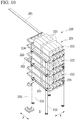
- FIG. 10 is a perspective view showing a capacitor unit of the first embodiment.
- the capacitor unit 220 includes the capacitor bank 221, capacitor support plates 231 on which the capacitor bank 221 is disposed, a plurality of (four in the present embodiment) insulation columns 233 that supports the capacitor support plates 231, and a charging section 235 that charges the capacitor bank 221.
- the capacitor bank 221 includes a plurality of (three in the present embodiment) capacitor modules 222 in which a plurality of (eight in the present embodiment) capacitors 223 is connected in parallel.
- the capacitor bank 221 is formed by the capacitor modules 222 being connected in series. As a result, the capacitor bank 221 can be regarded as one capacitor.
- the capacitor module 222 includes the plurality of capacitors 223, a first bus bar 224 that conducts first terminals of the plurality of capacitors 223 to each other, and a second bus bar 225 that conducts second terminals of the plurality of capacitors 223 to each other.
- the capacitor modules 221 are electrically connected to each other by a third bus bar 226.
- the capacitor support plate 231 supports one of the capacitor modules 222. Therefore, in the present embodiment, three capacitor support plates 231 are provided.
- the capacitor support plate 231 is formed of an insulation material such as fiber reinforced plastic, a metal material such as an aluminum alloy, or the like.
- the capacitor support plate 231 is formed in a rectangular shape in a plan view. In the present embodiment, the capacitor support plate 231 extends in both the first direction X and the second direction Y.
- the capacitor support plates 231 are stacked in a plurality of stages in the vertical direction with respect to the insulation columns 233.
- the insulation columns 233 are formed of, for example, an insulator, a polymer, a fiber reinforced plastic, or the like.
- the insulation columns 233 are erected on the foundation 5.
- the insulation columns 233 extend along the vertical direction.
- Each insulation column 233 supports a corner portion of each of the capacitor support plates 231 stacked in a plurality of stages.
- the insulation columns 233 fixedly support the capacitor support plates 231 and the capacitor bank 221 while electrically insulating the plurality of capacitor support plates 231 from each other and electrically insulating the capacitor bank 221 from the ground.
- the charging section 235 is installed on the foundation 5 beside the capacitor bank 221 and the capacitor support plate 231.
- the charging section 235 is disposed between the capacitor bank 221 and the mechanical circuit breaking section 2 (see FIG. 1 ).
- the charging section 235 is a resistor.
- the charging section 235 electrically connects a portion between the capacitor bank 221 and the closing device 241 in the commutation circuit 200 to the ground (see FIG. 8 ). That is, a first end portion of the charging section 235 is conductively connected to an end portion of the capacitor bank 221 on the closing device 241 side. A second end portion of the charging section 235 is grounded. As a result, the capacitor bank 221 can be charged by a potential difference between a system potential and a ground potential.
- the closing device unit 240 includes the closing device 241, a closing device support plate 243 on which the closing device 241 is disposed, a plurality of (four in the present embodiment) insulation columns 245 that supports the closing device support plate 243, and a power feeding section 247 that supplies electric power to the closing device 241.
- the closing device 241 is opened during normal power transmission of the direct-current power transmission system and breaks the commutation circuit 200.
- the closing device 241 is closed when the direct-current power transmission system is circuit-broken and makes both ends of the commutation circuit 200 be in a conducted state.
- At least one closing device 241 is provided.
- the plurality of closing devices 241 is connected in series to each other.
- a pair of closing devices 241 are provided.
- the closing device 241 is a high-speed closing device.
- the high-speed closing device is a closing device that can be closed at a higher speed than a mechanical contact which is driven by a hydraulic pressure, a restoring force of a spring, or an electromagnetic force of an electromagnetic solenoid.
- the closing device 241 is a discharge type closing device (a gap switch) that starts energization by lowering insulation performance between a pair of fixed electrodes 251 and 252 and causing insulation therebetween to break down (see Fig. 11 ).
- FIG. 11 is a partial cross-sectional view showing a closing device of the first embodiment.
- the closing device 241 includes a first electrode 251, a second electrode 252, a container 260 which houses the first electrode 251 and the second electrode 252, a trigger electrode 265 disposed close to the first electrode 251 in the container 260, a pulse power supply 267 which applies a pulse voltage between the first electrode 251 and the trigger electrode 265, and a connecting member 269 which connects the pulse power supply 267 and the container 260 to each other.
- the first electrode 251 and the second electrode 252 are each formed in a circular column shape having substantially the same diameter.
- the first electrode 251 and the second electrode 252 are disposed coaxially at intervals.
- Surfaces of the first electrode 251 and the second electrode 252, which face each other, are formed in a hemispherical shape.
- a through hole 251a in which the trigger electrode 265 is disposed is formed in the first electrode 251.
- the through hole 251a is formed coaxially with the central axis of the first electrode 251.
- the through hole 251a penetrates the first electrode 251 with a constant diameter.
- the container 260 is filled with dry air, sulfur hexafluoride (SF 6 ) gas, or the like.
- the container 260 includes a cylindrical insulation cylinder 261 having both ends open, a first flange 262 that closes a first end opening of the insulation cylinder 261, and a second flange 263 that closes a second end opening of the insulation cylinder 261.
- the insulation cylinder 261 surrounds the first electrode 251 and the second electrode 252.
- the insulation cylinder 261 is disposed coaxially with the first electrode 251 and the second electrode 252.
- the first flange 262 and the second flange 263 are each formed of a metal material.
- the first electrode 251 is fixed to the first flange 262.
- the first electrode 251 is conductively connected to the first flange 262.
- a through hole 262a coaxial with the through hole 251a of the first electrode 251 is formed in the first flange 262.
- a second electrode 252 is fixed to the second flange 263.
- the second flange 263 is conductively connected to the second electrode 252.
- the trigger electrode 265 is formed of a conductive material such as a metal or carbon in a needle shape having a tapered tip.
- a conductive material such as a metal or carbon in a needle shape having a tapered tip.
- stainless steel, copper, tungsten, or the like can be used as a metal conductive material.
- the trigger electrode 265 is inserted into the through hole 262a of the first flange 262 and the through hole 251a of the first electrode 251 from the outside of the container 260 such that the tip of the trigger electrode 265 faces the second electrode 252.
- An insulation support cylinder 271 is airtightly inserted onto an outer peripheral surface of the trigger electrode 265.
- the insulation support cylinder 271 is airtightly inserted into an inner peripheral surface of each of the through hole 262a of the first flange 262 and the through hole 251a of the first electrode 251.
- the trigger electrode 265 is supported by the first electrode 251 and the first flange 262 via the insulation support cylinder 271.
- the tip of the trigger electrode 265 is disposed at the same position as an end portion of the first electrode 251 on the second electrode 252 side in an extending direction of the first electrode 251.
- the pulse power supply 267 is disposed side by side with the container 260 to face the first flange 262 of the container 260.
- the pulse power supply 267 is formed in a rectangular parallelepiped shape.
- the pulse power supply 267 has a capacitor, a charging circuit for the capacitor, a resistor, a reactor, a switching device, and the like inside a housing that forms an outer shell.
- a first cable 273 and a second cable 275 extend from the pulse power supply 267.
- the first cable 273 is electrically connected to the proximal end of the trigger electrode 265.
- the second cable 275 is electrically connected to the first flange 262 of the container 260.
- the pulse power supply 267 When a command signal is input from the outside, the pulse power supply 267 outputs a pulse voltage between the first cable 273 and the second cable 275. As a result, a minute discharge is generated between the first electrode 251 and the trigger electrode 265, and thus plasma is generated around the first electrode 251. As a result, the insulation between the first electrode 251 and the second electrode 252 is broken to generate an arc, and an energization path passing through the first electrode 251 and the second electrode 252 is formed.
- the connecting member 269 is disposed between the container 260 and the pulse power supply 267.
- the connecting member 269 is formed of a metal material.
- the connecting member 269 is formed in a cylindrical shape having substantially the same diameter as the container 260.
- the connecting member 269 is disposed coaxially with the container 260 and surrounds the first cable 273 and the second cable 275.
- a first end opening of the connecting member 269 is electrically and mechanically connected to the first flange 262 of the container 260.
- a second end opening of the connecting member 269 is electrically and mechanically connected to the housing of the pulse power supply 267.
- the housing of the pulse power supply 267 has the same potential as the first electrode 251.
- a reference potential of the pulse power supply 267 becomes the same potential as the first electrode 251.
- a pair of closing devices 241 are disposed side by side in the horizontal direction.
- a first closing device 241 is disposed such that the container 260 is located on the capacitor unit 220 side in the first direction X with respect to the pulse power supply 267.
- a second closing device 241 is disposed side by side with respect to the pulse power supply 267 of the first closing device 241 on the surge absorbing section 3 side.
- the second closing device 241 is disposed such that the container 260 is located on the surge absorbing section 3 side in the second direction Y with respect to the pulse power supply 267.
- the closing device support plate 243 collectively supports the pair of closing devices 241.
- the closing device support plate 243 is formed of a metal material such as an aluminum alloy or the like.
- the closing device support plate 243 is formed in a rectangular shape in a plan view. In the present embodiment, the closing device support plate 243 extends in both the first direction X and the second direction Y.
- the closing device support plates 243 are stacked in a plurality of stages in the vertical direction with respect to the insulation columns 245.
- the closing device support plate 243 has the same potential as the housing of the pulse power supply 267 of each of the pair of closing devices 241. Specifically, the closing device support plate 243 has the same potential as a reference potential of the pulse power supply 267 of each of the pair of closing devices 241.
- the first electrode 251 of the closing device 241 is conductively connected to the housing of the pulse power supply 267 via the connecting member 269. Further, the housing of the pulse power supply 267 is conductively connected to the closing device support plate 243. As a result, the housings of the pair of pulse power supplies 267 are conductively connected to each other, and thus the first electrodes 251 of the pair of closing devices 241 are also connected to each other. The housings of the pair of pulse power supplies 267 may be conductively connected to each other by being adjacent to each other.
- an energization path from the second flange 263 of one closing device 241 to the second flange 263 of another closing device 241 is formed by the pair of closing devices 241 being closed.
- the first flanges 262 of the pair of closing devices 241 may be connected to each other by a bus bar (not shown) and the first flange 262 of the one closing device 241 and the connecting member 269 may be connected to each other via an insulation material (not shown), and thus the energization path from the second flange 263 of the one closing device 241 to the second flange 263 of the other closing device 241 may be limited to the bus bar (not shown).
- the insulation columns 245 are formed of, for example, an insulator, a polymer, a fiber reinforced plastic, or the like.
- the insulation columns 245 are erected on the foundation 5.
- the insulation columns 245 extend along the vertical direction.
- Each insulation column 245 supports a corner portion of the closing device support plate 243.
- the insulation columns 245 are shared with the insulation columns 215 of the reactor unit 210.
- the insulation columns 245 fixedly support the closing device support plate 243 and the closing devices 241 while electrically insulating the closing devices 241 from the ground.
- the power feeding section 247 is installed on the foundation 5 beside the closing device 241 and the closing device support plate 243.
- the power feeding section 247 is disposed between the closing device support plate 243 and the capacitor unit 220 (see FIG. 8 ).
- the power feeding section 247 supplies electric power to the pulse power supply 267 from above the ground.
- the power feeding section 247 supplies electric power while electrically insulating the ground and the pulse power supply 267 from each other.
- the power feeding section 247 is, for example, an insulation transformer.
- the containers 260 of the pair of closing devices 241 are disposed outside the closing device support plate 243 in the horizontal direction.
- the containers 260 of the pair of closing devices 241 are disposed to protrude from the closing device support plate 243 when seen in the vertical direction.
- the entire container 260 is disposed outside the closing device support plate 243 in the horizontal direction, but only a part of the container 260 may be disposed outside the closing device support plate 243 in the horizontal direction. It is sufficient that a portion (for example, the second flange 263) of the container 260 which has the same potential as the second electrode 252 is disposed outside the closing device support plate 243 in the horizontal direction.
- one electrical end of the reactor 211 is electrically connected to an end portion of the capacitor bank 221 on the supply point side of the direct-current power transmission system by a bus bar 201.
- the second flange 263 of the first closing device 241 is electrically connected to an end portion of the capacitor bank 221 on the demand point side of the direct-current power transmission system by a bus bar 202.
- the commutation circuit 200 has a configuration in which the reactor 211 and the closing device 241 are connected in series to both ends of the capacitor bank 221.
- the disposition of the reactor 211, the capacitor bank 221, and the closing device 241 in the commutation circuit 200 is not limited to the above example. It is sufficient that the charging section of the capacitor unit is connected between the closing device and the capacitor bank.
- the commutation device 4 includes a first connection point C1 and a second connection point C2 which are connected to the direct-current power transmission system.
- the first connection point C1 and the second connection point C2 are electrical end portions of the commutation circuit 200.
- the first connection point C1 is provided on the reactor 211.
- the first connection point C 1 constitutes an end portion of the commutation circuit 200 on the supply point side of the direct-current power transmission system.
- the second connection point C2 is provided on the second flange 263 of the second closing device 241.
- the second connection point C2 constitutes an end portion of the commutation circuit 200 on the demand point side of the direct-current power transmission system.
- the first connection point A1 of the mechanical circuit breaking section 2 and the first connection point B1 of the surge absorbing section 3 are electrically connected to each other by a bus bar 301.
- the second connection point A2 of the mechanical circuit breaking section 2 and the second connection point B2 of the surge absorbing section 3 are electrically connected to each other by a bus bar 302.
- the surge absorber 100 of the surge absorbing section 3 is connected in parallel to the mechanical contact module 90 of the mechanical circuit breaking section 2.
- the first connection point B 1 of the surge absorbing section 3 is electrically connected to a transmission line on the supply point side of the direct-current power transmission system by a bus bar 303.
- the second connection point B2 of the surge absorbing section 3 is electrically connected to a transmission line on the demand point side of the direct-current power transmission system by a bus bar 304.
- the mechanical contact module 90 of the mechanical circuit breaking section 2 constitutes a constant energization path of the direct-current power transmission system.
- the first connection point C1 of the commutation device 4 and the first connection point B1 of the surge absorbing section 3 are electrically connected to each other by a bus bar 305.
- the second connection point C2 of the commutation device 4 and the second connection point B2 of the surge absorbing section 3 are electrically connected to each other by a bus bar 306.
- the commutation circuit 200 of the commutation device 4 is connected in parallel to the surge absorber 100 of the surge absorbing section 3 and the mechanical contact module 90 of the mechanical circuit breaking section 2.
- the closing device 241 of the commutation device 4 is disposed on the most demand point side of the direct-current power transmission system in the commutation circuit 200.
- a transmission current flows through the mechanical contact module 90. In this state, no current is flowing through the surge absorber 100 and the commutation circuit 200. Further, the capacitor bank 221 of the commutation circuit 200 is charged by the charging section 235.
- a control device gives a closing command to the pulse power supply 267 of the closing device unit 240, and the pair of closing devices 241 are closed. Further, the mechanical contact portions 21 of all of the unitary circuit breakers 11 of the mechanical contact module 90 are opened. Specifically, a control device (not shown) gives a contact-opening operation command to the control section 13 of the mechanical circuit breaking unit 10 to open the mechanical contact portion 21 of each unitary circuit breaker 11. At this time, in each mechanical circuit breaking unit 10, the pair of operation rods 35 operate in opposite directions on the same straight line, and thus an impact force and a reaction generated in the operation mechanisms 37 are canceled out.
- the timing of closing the closing device 241 may be the same as the timing of opening the mechanical contact portion 21 of the unitary circuit breaker 11, or may be later than the timing of opening the mechanical contact portion 21 of the unitary circuit breaker 11. In general, the closing device 241 responds faster than the mechanical contact portion 21, and thus, by closing the closing device 241 at the above timing, it is possible to prevent the current zero point from being generated before the mechanical contact portion 21 is completely opened.
- the accident current is commutated to the surge absorber 100 connected in parallel to the mechanical contact module 90. After that, the energy of the accident current is absorbed by the surge absorber 100, and the breaking of the accident current of the direct-current power transmission system is completed.
- the direct-current circuit breaker 1 of the present embodiment has the mechanical contact module 90 formed by connecting all of the unitary circuit breakers 11 in series and the commutation circuit 200 connected in parallel to the mechanical contact module 90.
- the commutation circuit 200 is formed by the reactor 211, the capacitor bank 221, and the closing device 241 being connected in series.
- the closing device 241 is closed to discharge the electric charges of the capacitor bank 221, and the current zero point is generated in the mechanical contact module 90 connected in parallel to the commutation circuit 200 due to the LC resonance by the capacitor bank 221 and the reactor 211 in the commutation circuit 200. Therefore, the semiconductor circuit breaker connected in parallel to the mechanical contact module as in the related art is not required, and thus the equipment cost can be suppressed.
- the closing device 241 of the commutation device 4 a high-speed closing device is used. According to this configuration, it is possible to make the commutation circuit 200 be in a conducted state at a higher speed than a mechanical contact which is driven by a hydraulic pressure, a restoring force of a spring, or an electromagnetic force of an electromagnetic solenoid. Therefore, the current flowing through the mechanical contact module 90 can be broken at the same speed as the configuration using the semiconductor circuit breaker as in the related art.
- the closing device 241 of the present embodiment is a discharge type closing device that starts energization by lowering insulation performance between the pair of fixed electrodes 251 and 252 and causing insulation therebetween to break down.
- the closing device 241 has the container 260 which houses the first electrode 251 and the second electrode 252, and the pulse power supply 267 provided to have the same potential as the first electrode 251.
- the closing device support plate 243 is formed of a metal material and is provided to have the same potential as the pulse power supply 267.
- the container 260 of the closing device 241 is disposed outside the closing device support plate 243 in the horizontal direction.
- a portion (the second flange 263) of the container 260 which has the same potential as the second electrode 252 can be kept away from the closing device support plate 243 while the pulse power supply 267 can be kept close to the closing device support plate 243. Therefore, the closing device 241 and the closing device support plate 243 can be kept close to each other in the vertical direction while a portion of the container 260 which has the same potential as the second electrode 252 and the closing device support plate 243 can be insulated from each other, as compared with a case where the entire container 260 is disposed at a position to overlap the closing device support plate 243 in the horizontal direction. Therefore, it is possible to prevent the space in which the closing device 241 and the closing device support plate 243 are disposed from becoming larger in the vertical direction.
- the commutation device 4 includes the resistor (the charging section 235) that electrically connects a portion between the capacitor bank 221 and the closing device 241 to the ground.
- the capacitor bank 221 can be charged. Therefore, the configuration of the direct-current circuit breaker 1 can be simplified as compared with a case where a direct-current power source or the like for charging the capacitor bank is separately provided. Therefore, the equipment cost of the direct-current circuit breaker 1 can be further suppressed.
- the mechanical circuit breaking section 2 and the surge absorbing section 3 are disposed side by side in the first direction X.
- the commutation device 4 is disposed side by side in the second direction Y with respect to the mechanical circuit breaking section 2 and the surge absorbing section 3.
- the mechanical circuit breaking section 2, the surge absorbing section 3, and the commutation device 4 can be collectively disposed as compared with a case where the mechanical circuit breaking section, the surge absorbing section, and the commutation device are disposed side by side in a straight line. Therefore, the installation area of the direct-current circuit breaker 1 can be reduced.
- the reactor unit 210, the capacitor unit 220, and the closing device unit 240 are disposed at the same position in the second direction Y. According to this configuration, the space occupied by the commutation device 4 in the second direction Y can be made small as compared with a case where any of the reactor unit, the capacitor unit, and the closing device unit is arranged in the second direction Y when seen in the first direction X. Therefore, the mechanical circuit breaking section 2, the surge absorbing section 3, and the commutation device 4 can be disposed more collectively.
- the mechanical circuit breaking section 2 includes the power feeding unit 70 that supplies electric power to the operation mechanism 37 of the unitary circuit breaker 11.
- the power feeding unit 70 includes an insulation transformer. The insulation transformer is disposed between the mechanical circuit breaking units 10 and the commutation device 4.
- the unitary circuit breaker 11 has the mechanical contact portion 21 which has the fixed contact 22 and the movable contact 23 and is electrically insulated from the ground, the sealed container 30 which encloses the mechanical contact portion 21, is filled with the insulation gas, and is electrically insulated from the ground, the operation rod 35 which is connected to the movable contact 23, and the operation mechanism 37 which is connected to the operation rod 35 and is provided to have the same potential as the movable contact 23.
- the sealed container 30 since the sealed container 30 is not grounded to the ground, the insulation between the sealed container 30 and the mechanical contact portion 21 can be omitted. Therefore, the size of the sealed container 30 can be reduced and increase in the size of the unitary circuit breaker 11 can be suppressed as compared with a case where the sealed container is electrically insulated from the mechanical contact portion by being grounded to the ground or the like. Further, even in a case where, as the voltage increases, a plurality of unitary circuit breakers 11 is connected in series to improve the breaking performance, it is possible to suppress an increase in the size of all of the unitary circuit breakers 11 connected in series. Therefore, it is possible to provide the direct-current circuit breaker 1 which can easily increase the voltage and suppress the increase in size.
- the sealed container 30 and the operation mechanism 37 are not grounded to the ground, it is not necessary to insulate the mechanical contact portion 21 and the operation mechanism 37 from each other. Therefore, the mechanical contact portion 21 and the operation mechanism 37 can be disposed close to each other as compared with a case where the operation mechanism is electrically insulated from the mechanical contact portion by being grounded to the ground or the like. As a result, the lengthening of the operation rod 35 can be suppressed, the increase in the mass of a movable portion of the operation mechanism 37 can be suppressed, and the decrease in the opening speed of the mechanical contact portion 21 can be suppressed. Therefore, it is possible to provide a direct-current circuit breaker 1 capable of ensuring the responsiveness of the circuit breaking operation.
- each mechanical circuit breaking unit 10 is disposed such that the respective operation rods 35 operate on the same straight line by the operation mechanisms 37, and the operation directions of the operation rods 35 by the operation mechanisms 37 are opposite to each other.
- the pair of unitary circuit breakers 11 disposed on the mechanical breaker support plate 14 is disposed such that the respective operation mechanisms 37 are in contact with each other.
- the installation area of the direct-current circuit breaker 1 can be reduced as compared with a case where the mechanical circuit breaking units are disposed side by side in the horizontal direction.
- the mechanical circuit breaking unit 10 includes a mechanical breaker support plate 14 on which the pair of unitary circuit breakers 11 are disposed and which is supported by insulation columns 60.
- the mechanical breaker support plate 14 is formed of a metal material and is provided to have the same potential as the operation mechanisms 37 of the pair of the unitary circuit breakers 11. At least a part of the sealed container 30 of each of the pair of unitary circuit breakers 11 are disposed outside the mechanical breaker support plate 14 in the horizontal direction.
- a potion (the first flange 32) of the sealed container 30 which has the same potential as the fixed contact 22 can be kept away from the mechanical breaker support plate 14 while the operation mechanism 37 can be kept close to mechanical breaker support plate 14. Therefore, the unitary circuit breaker 11 and the mechanical breaker support plate 14 can be kept close to each other in the vertical direction while a portion of the sealed container 30 which has the same potential as the fixed contact 22 and the mechanical breaker support plate 14 can be insulated from each other, as compared with a case where the entire sealed container 30 is disposed at a position to overlap the mechanical breaker support plate 14 in the horizontal direction. Therefore, it is possible to suppress the increase in size of the mechanical circuit breaking section 2 in the vertical direction, and it is possible to suppress the bending moment generated in the insulation column 60 that supports the mechanical circuit breaking unit 10.
- the operation rod 35 of the unitary circuit breaker 11 has the rod insulation portion 35a that cuts off conduction between the movable contact 23 and the operation mechanism 37.
- the mechanical circuit breaking unit 10 has the in-unit bus bar 16 and the insulation portion 15a.
- the in-unit bus bar 16 electrically connects the second flanges 33 of the pair of unitary circuit breakers 11 to each other.
- the insulation portion 15a is provided in the support portion 15 interposed between the second flange 33 of one unitary circuit breaker 11 and the mechanical breaker support plate 14.
- the insulation portion 15a cuts off conduction between the second flange 33 of the one unitary circuit breaker 11 and the mechanical breaker support plate 14.
- the second flange 33 of another unitary circuit breaker 11 and the mechanical breaker support plate 14 are conductively connected to each other through the first support portion 15A.
- an energization path from the second flange 33 to the operation mechanism 37 through the operation rod 35 is cut off by the rod insulation portion 35a.
- an energization path from one second flange 33 through the mechanical breaker support plate 14 to another second flange 33 is cut off by the insulation portion 15a of the support portion 15. Therefore, in the mechanical circuit breaking unit 10, an energization path passing through the pair of unitary circuit breakers 11 are formed in the in-unit bus bar 16. As a result, it is possible to prevent partial discharge or insulation breakdown from occurring at an unintended portion such as the vicinity of the mechanical breaker support plate 14 or the operation mechanism 37. Therefore, the reliability of the mechanical circuit breaking unit 10 can be improved.
- the movable contact 23 and the operation mechanism 37 can be provided to have the same potential.
- FIG. 12 is a partial cross-sectional view showing a closing device of the second embodiment.
- the second embodiment shown in FIG. 12 is different from the first embodiment in that a closing device 341 is provided instead of the closing device 241 of the first embodiment.
- the configuration other than that described below is the same as that of the first embodiment.
- the closing device 341 is a high-speed closing device.
- the high-speed closing device is a closing device that can be closed at a higher speed than a mechanical contact which is driven by a hydraulic pressure, a restoring force of a spring, or an electromagnetic force of an electromagnetic solenoid.
- the closing device 341 is a discharge type closing device that starts energization by lowering insulation performance between a pair of fixed electrodes 351 and 352 and causing insulation therebetween to break down.
- the closing device 341 includes a first electrode 351, a second electrode 352, a container 360, and a trigger electrode 365 instead of the first electrode 251, the second electrode 252, the container 260, and the trigger electrode 265 in the closing device 241 of the first embodiment.
- the first electrode 351 and the second electrode 352 are formed in the same configuration as the first electrode 251 and the second electrode 252 of the first embodiment, except that the through hole is not formed in the first electrode 351.
- the container 360 houses the first electrode 351 and the second electrode 352.
- the container 360 is filled with dry air, sulfur hexafluoride (SF 6 ) gas, or the like.
- the container 360 includes a cylindrical insulation cylinder 361 having both ends open, a first flange 362 that closes a first end opening of the insulation cylinder 361, and a second flange 363 that closes a second end opening of the insulation cylinder 361.
- the insulation cylinder 361 surrounds the first electrode 351 and the second electrode 352.
- the insulation cylinder 361 is disposed coaxially with the first electrode 351 and the second electrode 352.
- the insulation cylinder 361 is divided at an intermediate portion of the insulation cylinder 361 in an extending direction and airtightly sandwiches an annular trigger electrode 365 described later therebetween.
- the first flange 362 and the second flange 363 are formed in the same configuration as the first flange 262 and the second flange 263 of the first embodiment, except that the through hole is not formed
- the trigger electrode 365 is disposed to surround a gap between the first electrode 351 and the second electrode 352.
- the trigger electrode 365 is formed of a conductive material such as a metal or carbon.
- a conductive material such as a metal or carbon.
- stainless steel, copper, tungsten, or the like can be used as a metal conductive material.
- the trigger electrode 365 is formed in an annular shape and is disposed coaxially with the first electrode 351 and the second electrode 352.
- the trigger electrode 365 is fixedly supported by the insulation cylinder 361 of the container 360.
- An inner peripheral portion of the trigger electrode 365 is formed to gradually become thinner from the outer side to the inner side in a radial direction.
- the trigger electrode 365 is electrically insulated from the first electrode 351 and the second electrode 352.
- the first cable 273 extending from the pulse power supply 267 is electrically connected to an outer peripheral portion of the trigger electrode 365.
- the pulse power supply 267 When a command signal is input from the outside, the pulse power supply 267 outputs a pulse voltage between the first cable 273 and the second cable 275. As a result, an electric field is concentrated between the first electrode 351 and the trigger electrode 365, and the electric field between the first electrode 351 and the second electrode 352 is distorted. As a result, the insulation between the first electrode 351 and the second electrode 352 is broken to generate an arc, and an energization path passing through the first electrode 351 and the second electrode 352 is formed.
- the closing device 341 of the present embodiment is a discharge type closing device that starts energization by lowering insulation performance between the pair of fixed electrodes 351 and 352 and causing insulation therebetween to break down. According to this configuration, the same effect as that of the first embodiment can be obtained.
- FIG. 13 is a perspective view showing a direct-current circuit breaker according to a third embodiment.
- the third embodiment shown in FIG. 13 is different from the first embodiment in that a charging section 335 is provided instead of the charging section 235 in the capacitor unit 220 of the first embodiment.
- the configuration other than that described below is the same as that of the first embodiment.
- the charging section 335 is installed on the foundation 5 beside the capacitor bank 221 and the capacitor support plate 231.
- the charging section 335 includes a direct-current power source 336 and an insulation transformer 337 that supplies electric power to the direct-current power source 336.
- the direct-current power source 336 is electrically connected to both ends of the capacitor bank 221.
- the direct-current power source 336 charges the capacitor bank 221 by applying a voltage to the both ends of the capacitor bank 221.
- the direct-current power source 336 is supported by a plurality of (four in the present embodiment) insulation columns 338.
- the insulation column 338 fixedly supports the direct-current power source 336 while electrically insulating the direct-current power source 336 from the ground.
- the insulation transformer 337 is installed on the foundation 5 below the direct-current power source 336.
- the insulation transformer 337 is disposed in a region surrounded by the plurality of insulation columns 338 when seen in the vertical direction.
- the insulation transformer 337 supplies electric power to the direct-current power source 336 from above the ground.
- the insulation transformer 337 supplies electric power while electrically insulating the ground and the direct-current power source 336 from each other.
- the charging section 335 of the present embodiment includes the direct-current power source 336 that applies a voltage to the both ends of the capacitor bank 221. According to this configuration, the capacitor bank 221 can be charged. Therefore, the same effect as that of the first embodiment can be obtained.
- FIG. 14 is a perspective view showing a direct-current circuit breaker according to a fourth embodiment.
- the fourth embodiment shown in FIG. 14 is different from the first embodiment in that a closing device unit 440 is provided instead of the closing device unit 240 of the first embodiment.
- the configuration other than that described below is the same as that of the first embodiment.
- the closing device unit 440 has a configuration in which a closing device 441, a power supply section 462, and a control section 463 instead of the closing device 241 of the first embodiment are disposed on the closing device support plate 243.
- At least one closing device 441 is provided.
- the closing device 441 is a high-speed closing device.
- the high-speed closing device is a closing device that can be closed at a higher speed than a mechanical contact which is driven by a hydraulic pressure, a restoring force of a spring, or an electromagnetic force of an electromagnetic solenoid.
- the closing device 441 is a mechanical closing device that drives a pair of contacts separated from each other with an electromagnetic repulsive force to bring the contacts into contact with each other and to energize the contacts.
- the closing device 441 has a configuration similar to that of the unitary circuit breaker 11 shown in FIG. 4 .
- the closing device 441 is formed in the same configuration as the unitary circuit breaker 11 except that the operation direction of the movable contact 23 (see FIG. 4 ) by a closing device operation mechanism 437 is different from that of the unitary circuit breaker 11.
- the mechanical contact portion 21 (see Fig. 4 ) of the closing device 441 is opened during normal power transmission of the direct-current power transmission system and breaks the commutation circuit 200.
- the mechanical contact portion 21 is closed when the direct-current power transmission system is circuit-broken and makes both ends of the commutation circuit 200 be in a conducted state.
- the closing device operation mechanism 437 is an electromagnetic repulsion type operation mechanism.
- the closing device operation mechanism 437 has a metal plate of a good conductor connected to the operation rod 35 (see FIG. 4 ) and a coil installed to face the metal plate.
- a current is applied to the coil to generate an induced current in a direction opposite to the metal plate, and an electromagnetic repulsive force in a direction opposite to the coil is applied to the metal plate to operate the operation rod 35.
- the mechanical contact portion 21 may be the contact of the vacuum interrupter 20 described above, or may be a gas contact.
- the pair of closing devices 441 are disposed such that the respective operation rods 35 operate on the same straight line when the mechanical contact portions 21 are closed by the closing device operation mechanisms 437. Specifically, the operation rods 35 of the respective closing devices 441 extend on the same straight line. In the present embodiment, the operation rod 35 operates in the second direction Y when the mechanical contact portion 21 is closed by the closing device operation mechanism 437. Further, the closing devices 441 are disposed such that operation directions of the operation rods 35 are opposite to each other when the mechanical contact portions 21 are closed by the closing device operation mechanisms 437. Specifically, the pair of closing devices 441 are disposed such that the respective closing device operation mechanisms 437 are in contact with each other.
- the power supply section 462 supplies electric power to the closing device operation mechanisms 437 of the pair of closing devices 441.
- the power supply section 462 is provided such that a reference potential becomes the same potential as the closing device operation mechanism 437.
- the power supply section 462 includes, for example, a capacitor that supplies electric power to the closing device operation mechanism 437 when the mechanical contact portion 21 of the closing device 441 is opened, and a capacitor that supplies electric power to the closing device operation mechanism 437 when the mechanical contact portion 21 of the closing device 441 is closed, a charging device for each capacitor, and a switching element for holding each capacitor in a charged state and discharging when electric power is supplied (none of these is shown).
- the power supply section 462 is supplied with electric power from the power feeding section 247.
- the control section 463 monitors the state of the power supply section 462 and the closing device operation mechanisms 437 of the pair of closing devices 441. Further, the control section 463 controls the electric power supply from the power supply section 462 to the closing device operation mechanisms 437 of the pair of closing devices 441.
- At least a part of the sealed container 30 of each of the pair of closing devices 441 are disposed outside the closing device support plate 243 in the horizontal direction.
- the sealed containers 30 of the pair of closing devices 441 are disposed to protrude from the closing device support plate 243 when seen in the vertical direction.
- only a part of the sealed container 30 is disposed outside the closing device support plate 243 in the horizontal direction, but the entire sealed container 30 may be disposed outside the closing device support plate 243 in the horizontal direction. It is sufficient that a portion (for example, the first flange 32) of the sealed container 30 which has the same potential as the fixed contact 22 is disposed outside the closing device support plate 243 in the horizontal direction.
- a support portion 465 is interposed between the pair of closing devices 441 and the closing device support plate 243.
- the support portion 465 is formed in the same configuration as the support portion 15 in the mechanical circuit breaking unit 10.
- the pair of closing devices 441 are connected in series by a bus bar 466.
- the bus bar 466 is formed in the same configuration as the in-unit bus bar 16 in the mechanical circuit breaking unit 10.
- the closing device 441 of the present embodiment is a mechanical closing device that drives a pair of contacts separated from each other with an electromagnetic repulsive force to bring the contacts into contact with each other and to energize the contacts. According to this configuration, it is possible to configure a high-speed closing device that can be closed at a higher speed than a mechanical contact which is driven by a hydraulic pressure, a restoring force of a spring, or an electromagnetic force of an electromagnetic solenoid. Therefore, the same effect as that of the first embodiment can be obtained.
- the closing device support plate 243 is formed of a metal material and is provided to have the same potential as the closing device operation mechanisms 437 of the pair of closing devices 441. At least a part of the sealed container 30 of each of the pair of closing devices 441 is disposed outside the closing device support plate 243 in the horizontal direction.
- a potion (the first flange 32) of the sealed container 30 which has the same potential as the fixed contact 22 can be kept away from the closing device support plate 243 while the closing device operation mechanism 437 can be kept close to the closing device support plate 243. Therefore, the closing device 441 and the closing device support plate 243 can be kept close to each other in the vertical direction while a portion of the sealed container 30 which has the same potential as the fixed contact 22 and the closing device support plate 243 can be insulated from each other, as compared with a case where the entire sealed container 30 is disposed at a position to overlap the closing device support plate 243 in the horizontal direction. Therefore, it is possible to prevent the space in which the closing device 441 and the closing device support plate 243 are disposed from becoming larger in the vertical direction.
- FIG. 15 is a perspective view showing a direct-current circuit breaker according to a fifth embodiment.
- the fifth embodiment shown in FIG. 15 is different from the first embodiment in that the mechanical circuit breaking section 2, the surge absorbing section 3, and the commutation device 4 are disposed side by side in a straight line.
- the configuration other than that described below is the same as that of the first embodiment.
- the mechanical circuit breaking section 2, the surge absorbing section 3, and the commutation device 4 are disposed side by side in the first direction X.
- the sealed containers 30 of the pair of unitary circuit breakers 11 of each mechanical circuit breaking unit 10 are disposed to protrude from the mechanical breaker support plate 14 in the first direction X.
- the power feeding unit 70 is disposed on one side of the second directions Y with respect to the mechanical circuit breaking unit 10.
- the surge absorbing section 3 is adjacent to the mechanical circuit breaking section 2. That is, the surge absorbing section 3 is disposed between the mechanical circuit breaking section 2 and the commutation device 4.
- the reactor unit 210 and the closing device unit 240 are disposed to be lined up with the capacitor unit 220 in the first direction X.
- the reactor unit 210 and the closing device unit 240 are disposed between the surge absorbing section 3 and the capacitor unit 220.
- the reactor 211 is supported at both end portions thereof in the first direction X by the pair of stays 213.
- the charging section 235 is disposed on the one side in the second direction Y with respect to the capacitor support plate 231.
- the containers 260 of the pair of closing devices 241 are disposed to protrude from the closing device support plate 243 in the first direction X.
- the power feeding section 247 is disposed on the one side in the second direction Y with respect to the closing device support plate 243.
- the mechanical circuit breaking section 2, the surge absorbing section 3, and the commutation device 4 are disposed side by side in the first direction X.
- the direct-current circuit breaker 1 can be disposed.
- the present invention is not limited to this configuration.
- a laser trigger method that induces insulation breakdown by irradiating a portion between electrodes with a laser to ionize an insulation medium may be applied.
- the trigatron method and the electric field distortion method are advantageous from the viewpoint of suppressing the equipment cost.
- the electric field distortion method and the laser trigger method are advantageous from the viewpoint of the lifespan of the closing device.
- the closing device unit includes a pair of closing devices, but the present invention is not limited to this configuration.
- the closing device unit may include only one closing device, or may include three or more closing devices. Further, the closing device unit may include both of the discharge type closing device and the mechanical closing device.
- the mechanical circuit breaking unit 10 includes a pair of unitary circuit breakers 11, but the present invention is not limited to this configuration.
- the mechanical circuit breaking unit may include only one unitary circuit breaker, or may include three or more unitary circuit breakers. Further, the mechanical circuit breaking section may include only the vacuum circuit breaker 11A or only the gas disconnector 11B as the unitary circuit breaker 11.
- the commutation circuit connected in parallel to the mechanical contact module is formed by the reactor, the capacitor bank, and the closing device being connected in series.
- the semiconductor circuit breaker connected in parallel to the mechanical contact module as in the related art is not required, and thus the equipment cost can be suppressed.
- the closing device of the commutation device is a high-speed closing device, the current flowing through the mechanical contact module can be broken at the same speed as the configuration using the semiconductor circuit breaker as in the related art. As described above, it is possible to provide a direct-current circuit breaker capable of shortening the current breaking time and suppressing the equipment cost.
Landscapes
- Engineering & Computer Science (AREA)
- Power Engineering (AREA)
- Gas-Insulated Switchgears (AREA)
- Driving Mechanisms And Operating Circuits Of Arc-Extinguishing High-Tension Switches (AREA)
- Keying Circuit Devices (AREA)
Abstract
Description
- Embodiments of the present invention relate to a direct-current circuit breaker.
- Direct-current power transmission has higher power transmission efficiency than alternating-current power transmission. On the other hand, the introduction cost of equipment is higher for direct-current power transmission. However, in long-distance power transmission or underwater power transmission, power transmission efficiency of direct-current power transmission is predominantly high, and thus, when evaluation is performed for equipment costs together with operating costs, direct-current power transmission is generally lower in cost. For this reason, direct-current power transmission is used for power transmission between two bases across the sea, for example. In recent years, to improve the ratio of generated electric power using renewable energy to total generated electric power and to cover more electric power with the renewable energy, a method of performing large-scale power generation in a place far from urban areas, which are main electric power consuming areas, using offshore wind power generation or solar power generation in desert areas and transmitting the generated electric power over a long distance is being studied. Along with this, there are plans to construct a direct-current power transmission network connecting a plurality of electric power supply points and demand points.
- When a power transmission network connecting three or more bases is constructed, in a case in which an accident occurs in the power transmission network, a device capable of quickly breaking an accident point from a sound system is required. Generally, a mechanical contact type circuit breaker is used in an alternating-current system. The mechanical contact type circuit breaker breaks an accident current by opening contacts at a current zero point generated by an alternating current and blowing an insulation medium to an arc current between the contacts. On the other hand, in a direct-current power transmission system, the current zero point does not occur in the accident current, and thus it is difficult to quickly break the accident current with the mechanical contact type circuit breaker of the related art.
- Therefore, as a semiconductor circuit breaker capable of breaking a direct current independently, a semiconductor circuit breaker using a plurality of self-excited semiconductor elements having a self-extinguishing ability, such as an insulated gate bipolar transistor (IGBT), has been proposed. However, since the total electric power to be transmitted always passes through the plurality of self-excited semiconductor elements, a large conduction loss occurs, which causes a decrease in power transmission efficiency during normal operation.
- To solve this problem, a hybrid circuit breaker in which another semiconductor circuit breaker is connected in parallel to a circuit in which a mechanical contact type disconnector and an auxiliary semiconductor circuit breaker are connected in series has been proposed. In this hybrid circuit breaker, during normal power transmission, the mechanical contact type disconnector and the auxiliary semiconductor circuit breaker are in a conducted state, and the other semiconductor circuit breaker described above is in a circuit-broken state. Therefore, a transmission current flows between the mechanical contact type disconnector and the auxiliary semiconductor circuit breaker.
- Further, in the event of an accident, a contact-opening command is given to the mechanical contact type disconnector at the same time at which the auxiliary semiconductor circuit breaker enters a circuit-broken state. When the auxiliary semiconductor circuit breaker is in a circuit-broken state in this way, an accident current flowing along a path between the mechanical contact type disconnector and the auxiliary semiconductor circuit breaker is commutated to the other semiconductor circuit breaker described above. Then, after a contact-opening operation of the mechanical contact type disconnector is completed and the withstand voltage performance of a normal energization path is secured, the other semiconductor circuit breaker described above is circuit-broken to complete the breaking of the accident current.
- In such a hybrid circuit breaker, a conduction loss during normal power transmission is only a conduction loss of the auxiliary semiconductor circuit breaker, and thus the conduction loss can be reduced as compared with the configuration in which the normal energization path is constituted by only the semiconductor circuit breaker capable of breaking the direct current independently as described above. However, since an energization loss of the auxiliary semiconductor circuit breaker still occurs, the hybrid circuit breaker has a larger conduction loss than the mechanical contact type circuit breaker of the related art in which the normal energization path is constituted by only the mechanical contacts.
- Therefore, a direct-current circuit breaker in which a mechanical contact type circuit breaker is connected in parallel to a circuit in which a semiconductor circuit breaker and a commutation circuit constituted by a half-bridge circuit are connected in series has been proposed. In this direct-current circuit breaker, during normal power transmission, the mechanical contact type disconnector is in a conducted state, and the semiconductor circuit breaker and the commutation circuit are in a circuit-broken state. Therefore, a transmission current at the time of normal power transmission flows through only the mechanical contact type disconnector.
- Further, in the event of an accident, a contact-opening command is given to the mechanical contact type circuit breaker, the semiconductor circuit breaker enters a conducted state, and a commutation command is given to the commutation circuit. Then, the commutation circuit causes a current to flow in a direction opposite to the accident current flowing in the mechanical contact type circuit breaker to generate a zero point in the current of the mechanical contact type circuit breaker, the contacts of the mechanical contact type circuit breaker are opened, and thus the accident current is commutated from the mechanical contact type circuit breaker to the semiconductor circuit breaker and the commutation circuit. After the accident current is commutated, the semiconductor breaker is circuit-broken to complete the breaking of the accident current.
- In such a direct-current circuit breaker, since the normal energization path is constituted by only the mechanical contact type circuit breaker, the conduction loss can be significantly reduced. However, in the hybrid circuit breaker, since the semiconductor circuit breaker is expensive, the equipment cost may significantly increase as compared with the mechanical contact type circuit breaker of the related art.
-
- [Patent Document 1]
PCT International Publication No. WO2015/166600 - [Patent Document 2]
PCT International Publication No. WO2016/056274 - [Patent Document 3]
PCT International Publication No. WO2017/134825 - An object of the present invention is to provide a direct-current circuit breaker capable of shortening the current breaking time and suppressing the equipment cost.
- A direct-current circuit breaker according to an embodiment includes a mechanical circuit breaking section, a surge absorber, and a commutation device. The mechanical circuit breaking section has at least one mechanical circuit breaking unit and an insulation column. The at least one mechanical circuit breaking unit has at least one unitary circuit breaker. The insulation column supports the at least one mechanical circuit breaking unit. Each of the at least one unitary circuit breaker has a mechanical contact portion, a sealed container, an operation rod, and an operation mechanism. The mechanical contact portion has a fixed contact and a movable contact. The mechanical contact portion is electrically insulated from the ground. The sealed container encloses the mechanical contact portion and is filled with an insulation gas. The sealed container is electrically insulated from the ground. The operation rod is connected to the movable contact. The operation rod extends from the inside of the sealed container to the outside thereof. The operation mechanism is connected to the operation rod. The operation mechanism is configured to bring the movable contact in and out of contact with the fixed contact. The operation mechanism is provided to have the same potential as the movable contact. The at least one unitary circuit breaker has a first unitary circuit breaker and a second unitary circuit breaker. The first unitary circuit breaker and the second unitary circuit breaker are disposed such that the respective operation rods operate on the same straight line by the operation mechanisms, and the operation directions of the operation rods by the operation mechanisms are opposite to each other. The first unitary circuit breaker and the second unitary circuit breaker are disposed such that the respective operation mechanisms face each other. All of the at least one unitary circuit breaker are connected in series to form a mechanical contact module. Both ends of the mechanical contact module are connected to a direct-current power transmission system. The surge absorber is connected in parallel to the mechanical contact module. The commutation device has a commutation circuit. The commutation circuit is formed by a reactor, a capacitor, and a closing device being connected in series. The commutation circuit is connected in parallel to the mechanical contact module. The closing device is a high-speed closing device.
-
-
FIG. 1 is a perspective view showing a direct-current circuit breaker according to a first embodiment. -
FIG. 2 is a circuit diagram showing the direct-current circuit breaker according to the first embodiment. -
FIG. 3 is a perspective view showing a mechanical circuit breaking section of the first embodiment. -
FIG. 4 is a partial cross-sectional view of a mechanical circuit breaking unit of the first embodiment from the side. -
FIG. 5 is a cross-sectional view showing a gas disconnector according to the first embodiment. -
FIG. 6 is a view showing an energization path in the mechanical circuit breaking unit of the first embodiment. -
FIG. 7 is a perspective view showing a surge absorbing section of the first embodiment. -
FIG. 8 is a perspective view showing a commutation device according to the first embodiment. -
FIG. 9 is a perspective view showing a reactor unit and a closing device unit according to the first embodiment. -
FIG. 10 is a perspective view showing a capacitor unit of the first embodiment. -
FIG. 11 is a partial cross-sectional view showing a closing device of the first embodiment. -
FIG. 12 is a partial cross-sectional view showing a closing device of a second embodiment. -
FIG. 13 is a perspective view showing a direct-current circuit breaker according to a third embodiment. -
FIG. 14 is a perspective view showing a direct-current circuit breaker according to a fourth embodiment. -
FIG. 15 is a perspective view showing a direct-current circuit breaker according to a fifth embodiment. - Hereinafter, a direct-current circuit breaker of each of embodiments will be described with reference to the drawings. In the following description, the same reference signs are given to constituent elements having the same or similar functions. Further, duplicate description of those constituent elements may be omitted.
-
FIG. 1 is a perspective view showing a direct-current circuit breaker according to a first embodiment.FIG. 2 is a circuit diagram showing the direct-current circuit breaker according to the first embodiment. - As shown in
FIGS. 1 and2 , the direct-current circuit breaker 1 includes a mechanicalcircuit breaking section 2, asurge absorbing section 3, and acommutation device 4. The direct-current circuit breaker 1 is installed on afoundation 5 on the ground. An upper surface of thefoundation 5 is horizontally formed. In the present embodiment, one horizontal direction is defined as a first direction, and a horizontal direction orthogonal to the first direction is defined as a second direction. Further, reference sign X is given to the first direction, and reference sign Y is given to the second direction. The mechanicalcircuit breaking section 2 and thesurge absorbing section 3 are disposed side by side in the first direction X. A state in which a plurality of objects is disposed side by side in the first direction X is a state in which the objects are disposed to overlap each other when seen in the first direction X. Thecommutation device 4 is disposed side by side in the second direction Y with respect to the mechanicalcircuit breaking section 2 and thesurge absorbing section 3. - The mechanical
circuit breaking section 2 will be described. -
FIG. 3 is a perspective view showing a mechanical circuit breaking section of the first embodiment. - As shown in
FIG. 3 , the mechanicalcircuit breaking section 2 includes a plurality of (two in the present embodiment) mechanicalcircuit breaking units 10, a plurality of (four in the present embodiment)insulation columns 60 that supports the mechanicalcircuit breaking units 10, and apower feeding unit 70 that supplies electric power to the mechanicalcircuit breaking units 10. The plurality of mechanicalcircuit breaking units 10 is stacked in a plurality of stages in a vertical direction with respect to theinsulation columns 60. - Each of the mechanical
circuit breaking units 10 includes a pair of unitary circuit breakers 11 (a first unitary circuit breaker and a second unitary circuit breaker), apower supply section 12, acontrol section 13, and mechanicalbreaker support plate 14 on which the pair ofunitary circuit breakers 11, thepower supply section 12, and thecontrol section 13 are disposed. - Each of the
unitary circuit breakers 11 includes amechanical contact portion 21 which has a fixedcontact 22 and a movable contact 23 (seeFIG. 4 ). Themechanical contact portion 21 is opened by themovable contact 23 being separated from the fixedcontact 22. Theunitary circuit breaker 11 circuit-breaks an energization path passing through themechanical contact portion 21 by opening themechanical contact portion 21. Theunitary circuit breaker 11 constitutes avacuum circuit breaker 11A or agas disconnector 11B. Thevacuum circuit breaker 11A has avacuum interrupter 20 in which themechanical contact portion 21 is disposed in a vacuum insulation cylinder 24 (seeFIG. 4 ). The gas disconnector 11B has a gas contact in which themechanical contact portion 21 is disposed in an insulation gas. Themechanical contact portion 21 of thevacuum circuit breaker 11A is a contact capable of mechanically breaking a current at a current zero point. The current breaking performance of thevacuum circuit breaker 11A is higher than that of thegas disconnector 11B. The withstand voltage performance of thegas disconnector 11B is higher than or equivalent to that of thevacuum circuit breaker 11A. - In each mechanical
circuit breaking unit 10, it is desirable that the pair ofunitary circuit breakers 11 have the same configuration. In the present embodiment, the mechanicalcircuit breaking unit 10 includes only thevacuum circuit breaker 11A or only thegas disconnector 11B. For example, the mechanicalcircuit breaking unit 10 on an upper stage includes a pair ofvacuum circuit breakers 11A. Further, the mechanicalcircuit breaking unit 10 on a lower stage includes a pair ofgas disconnectors 11B. -
FIG. 4 is a partial cross-sectional view of a mechanical circuit breaking unit of the first embodiment from the side.FIG. 4 shows the mechanicalcircuit breaking unit 10 provided with thevacuum circuit breaker 11A as theunitary circuit breaker 11. - As shown in
FIG. 4 , thevacuum circuit breaker 11A includes thevacuum interrupter 20 having themechanical contact portion 21, a sealedcontainer 30 enclosing thevacuum interrupter 20, anenergization shaft 34 connected to the fixedcontact 22 of themechanical contact portion 21, anoperation rod 35 connected to themovable contact 23 of themechanical contact portion 21, anoperation mechanism 37 connected to theoperation rod 35, and a capacitor 39 (seeFIG. 3 ) connected in parallel to themechanical contact portion 21. - The
vacuum interrupter 20 includes the above-mentionedmechanical contact portion 21, theinsulation cylinder 24 that encloses themechanical contact portion 21, and abellows 25 provided inside theinsulation cylinder 24. - The fixed
contact 22 and themovable contact 23 of themechanical contact portion 21 are provided to be able to come in and out of contact with each other. The fixedcontact 22 is fixedly disposed with respect to theinsulation cylinder 24. Themovable contact 23 is provided to be displaceable with respect to theinsulation cylinder 24. In the following description of theunitary circuit breaker 11, a direction in which the fixedcontact 22 and themovable contact 23 come in and out of contact with each other is referred to as a contact operation direction. In the present embodiment, the contact operation direction is one horizontal direction and is parallel to the first direction X. - The
insulation cylinder 24 is formed in a cylindrical shape extending along the contact operation direction. Theinsulation cylinder 24 is, for example, a bushing formed of an insulation material. The inside of theinsulation cylinder 24 is maintained in a vacuum. A through hole into which theenergization shaft 34 is airtightly inserted is formed in a first end portion of theinsulation cylinder 24. A through hole into which theoperation rod 35 is inserted is formed in a second end portion of theinsulation cylinder 24. - The bellows 25 is disposed inside the
insulation cylinder 24 to surround theoperation rod 35. One end portion of thebellows 25 is fixed to an outer peripheral surface of themovable contact 23. Another end of thebellows 25 is fixed to the second end portion of theinsulation cylinder 24. The bellows 25 maintains the vacuum inside thevacuum interrupter 20 while allowing themovable contact 23 and theoperation rod 35 to be displaced with respect to theinsulation cylinder 24. - The sealed
container 30 is filled with, for example, sulfur hexafluoride (SF6) gas as the insulation gas. The sealedcontainer 30 includes acylindrical insulation cylinder 31, and afirst flange 32 and asecond flange 33 which close both end openings of theinsulation cylinder 31. Theinsulation cylinder 31 extends along the contact operation direction. Theinsulation cylinder 31 is, for example, a bushing formed of an insulation material. Thefirst flange 32 and thesecond flange 33 are each formed of a metal material. - The
energization shaft 34 is fixed to thefirst flange 32 of the sealedcontainer 30. Theenergization shaft 34 is disposed to penetrate theinsulation cylinder 24 of thevacuum interrupter 20. Theenergization shaft 34 fixedly supports thevacuum interrupter 20 with respect to the sealedcontainer 30. Theenergization shaft 34 fixedly supports the fixedcontact 22 in theinsulation cylinder 24 of thevacuum interrupter 20. Theenergization shaft 34 is formed of a conductive material such as a metal and is conductively connected to the fixedcontact 22. Theenergization shaft 34 conducts the fixedcontact 22 and thefirst flange 32 of the sealedcontainer 30 to each other. In addition, "conduction" refers to a state in which a plurality of objects are electrically connected to each other and have the same potential. Further, even in a case in which a potential difference occurs due to impedances of the plurality of objects, when the potential difference is small enough to be negligible (for example, several tens of volts or less) compared to the rated voltage of equipment, each potential is treated as the same potential. - The
operation rod 35 extends along the contact operation direction. The first end portion of theoperation rod 35 is coupled to themovable contact 23 in theinsulation cylinder 24 of thevacuum interrupter 20. Theoperation rod 35 is slidably provided in the contact operation direction with respect to the second end portion of theinsulation cylinder 24. Theoperation rod 35 extends from the inside of the sealedcontainer 30 to the outside of the sealedcontainer 30 through a throughhole 33a provided in thesecond flange 33. Theoperation rod 35 is provided to be conducted and slidable with respect to thesecond flange 33 while maintaining airtightness inside the sealedcontainer 30. A portion of theoperation rod 35 extending from the first end portion to a sliding portion with thesecond flange 33 is formed of a conductive material such as a metal. As a result, theoperation rod 35 conducts themovable contact 23 and thesecond flange 33 to each other. At least a part of theoperation rod 35 located outside the sealedcontainer 30 is provided with arod insulation portion 35a that electrically insulates both end portions of theoperation rod 35 from each other. - The
operation mechanism 37 is a highly responsive electromagnetic actuator that operates with electric power. The electromagnetic actuator is, for example, an electromagnetic repulsion type operation mechanism. The electromagnetic repulsiontype operation mechanism 37 has a metal plate of a good conductor connected to the second end portion of theoperation rod 35 and a coil installed to face the metal plate. At the time of driving, a current is applied to the coil to generate an induced current in a direction opposite to the metal plate, and an electromagnetic repulsive force in a direction opposite to the coil is applied to the metal plate to operate theoperation rod 35. - The
operation mechanism 37 is disposed side by side with thesecond flange 33 in the contact operation direction on the outside of the sealedcontainer 30. Theoperation mechanism 37 is connected to thesecond flange 33 by a connectingmember 38. At least a part of the connectingmember 38 is formed of an insulation material to electrically insulate both end portions of the connectingmember 38 from each other. Theoperation mechanism 37 reciprocates theoperation rod 35 in the contact operation direction. As a result, theoperation mechanism 37 displaces themovable contact 23 fixedly provided with respect to theoperation rod 35 and brings themovable contact 23 in and out of contact with the fixedcontact 22. - As shown in
FIG. 3 , thecapacitor 39 is disposed outside the sealedcontainer 30. Thecapacitor 39 is electrically and mechanically connected to thefirst flange 32 and thesecond flange 33 of the sealedcontainer 30. Thecapacitor 39 includes a high resistance cylinder filled with a dielectric material and electrodes at both ends and has capacitance and resistance. Thecapacitor 39 adjusts a voltage applied to the mechanical contact portion 21 (seeFIG. 4 ) during current breaking and in a contact-opened state. -
FIG. 5 is a cross-sectional view showing a gas disconnector according to the first embodiment. - As shown in
FIG. 5 , thegas disconnector 11B differs from thevacuum circuit breaker 11A in that themechanical contact portion 21 is directly disposed in the sealedcontainer 30. That is, in thegas disconnector 11B, the insulation gas is interposed between the fixedcontact 22 and themovable contact 23 in the contact-opened state of themechanical contact portion 21. - As shown in
FIG. 3 , in each mechanicalcircuit breaking unit 10, the pair ofunitary circuit breakers 11 are disposed such that therespective operation rods 35 operate on the same straight line when themechanical contact portions 21 are opened by theoperation mechanisms 37. Specifically, in each mechanicalcircuit breaking unit 10, theoperation rods 35 of the respectiveunitary circuit breakers 11 extend on the same straight line. In the present embodiment, theoperation rod 35 operates in the first direction X when themechanical contact portion 21 is opened by theoperation mechanism 37. Further, in each mechanicalcircuit breaking unit 10, the pair ofunitary circuit breakers 11 are disposed such that operation directions of theoperation rods 35 are opposite to each other when themechanical contact portions 21 are opened by theoperation mechanisms 37. Specifically, in each mechanicalcircuit breaking unit 10, the pair ofunitary circuit breakers 11 are disposed such that therespective operation mechanisms 37 are in contact with each other. Further, theunitary circuit breaker 11 of one mechanicalcircuit breaking unit 10 and theunitary circuit breaker 11 of another mechanicalcircuit breaking unit 10 are disposed to operate on the same straight line when seen in the vertical direction. - The
power supply section 12 supplies electric power to theoperation mechanisms 37 of the pair ofunitary circuit breakers 11. Thepower supply section 12 is provided such that a reference potential becomes the same potential as that of theoperation mechanism 37. Thepower supply section 12 includes, for example, a capacitor that supplies electric power to theoperation mechanism 37 when the mechanical contact portion 21 (seeFIG. 4 ) is opened, and a capacitor that supplies electric power to theoperation mechanism 37 when themechanical contact portion 21 is closed, a charging device for each capacitor, and a switching element for holding each capacitor in a charged state and discharging when electric power is supplied (none of these is shown). - The
control section 13 monitors the state of thepower supply section 12 and theoperation mechanisms 37 of the pair ofunitary circuit breakers 11. Further, thecontrol section 13 controls the electric power supply from thepower supply section 12 to theoperation mechanisms 37 of the pair ofunitary circuit breakers 11. - The mechanical
breaker support plate 14 supports the pair ofunitary circuit breakers 11, thepower supply section 12, and thecontrol section 13 from below. For example, the mechanicalbreaker support plate 14 is formed of a metal material such as an aluminum alloy. The mechanicalbreaker support plate 14 is formed in a rectangular shape in a plan view. The mechanicalbreaker support plate 14 is disposed such that the two sides of the outer edge are parallel to the contact operation direction. In the present embodiment, the mechanicalbreaker support plate 14 extends in both the first direction X and the second direction Y. The mechanicalbreaker support plates 14 are stacked in a plurality of stages in the vertical direction with respect to theinsulation columns 60. - In each mechanical
circuit breaking unit 10, at least a part of the sealedcontainer 30 of each of the pair ofunitary circuit breakers 11 are disposed outside the mechanicalbreaker support plate 14 in the horizontal direction. In other words, the sealedcontainer 30 of each of the pair ofunitary circuit breakers 11 are disposed to protrude from the mechanicalbreaker support plate 14 when seen in the vertical direction. In the illustrated example, only a part of the sealedcontainer 30 is disposed outside the mechanicalbreaker support plate 14 in the horizontal direction, but the entire sealedcontainer 30 may be disposed outside the mechanicalbreaker support plate 14 in the horizontal direction. It is sufficient for a portion (for example, the first flange 32) of the sealedcontainer 30 which has the same potential as the fixedcontact 22 to be disposed outside the mechanicalbreaker support plate 14 in the horizontal direction. - Here, a part of the sealed container being disposed outside the mechanical
breaker support plate 14 in the horizontal direction will be described in another way with reference toFIG. 3 . - For example, assuming that the above-mentioned contact operation direction is regarded as a projection line, two vertical projection planes including two sides having a twisted positional relationship with the projection line among four sides constituting the mechanical
breaker support plate 14 can be defined. It is sufficient for at least a part of the sealedcontainer 30 to be disposed to protrude from a space separated by the two vertical projection planes (a space on a side where theoperation mechanism 37 is). - As shown in
FIG. 4 , the mechanicalcircuit breaking unit 10 further includes asupport portion 15 and an in-unit bus bar 16 (a conductive member). - The
support portion 15 is interposed between each of the pair ofunitary circuit breakers 11 and the mechanicalbreaker support plate 14. Thesupport portion 15 supports theunitary circuit breakers 11 while floating them from the mechanicalbreaker support plate 14. Thesupport portion 15 includes a pair offirst support portions 15A interposed between thesecond flanges 33 of theunitary circuit breakers 11 and the mechanicalbreaker support plate 14, and a pair ofsecond support portions 15B interposed between theoperation mechanisms 37 of theunitary circuit breakers 11 and the mechanicalbreaker support plate 14. Onefirst support portion 15A includes aninsulation portion 15a that cuts off electrical conduction between thesecond flange 33 and the mechanicalbreaker support plate 14. As a result, thesecond flange 33 of theunitary circuit breaker 11 supported by the onefirst support portion 15A is electrically insulated from the mechanicalbreaker support plate 14. Anotherfirst support portion 15A conducts thesecond flange 33 of theunitary circuit breaker 11 and the mechanicalbreaker support plate 14 to each other. Thesecond support portion 15B conducts theoperation mechanism 37 and the mechanicalbreaker support plate 14 to each other. - The in-
unit bus bar 16 connects the pair ofunitary circuit breakers 11 in series. The in-unit bus bar 16 is electrically and mechanically connected to each of thesecond flanges 33 of the pair ofunitary circuit breakers 11. The in-unit bus bar 16 extends above theoperation mechanism 37 of the pair ofunitary circuit breakers 11 to straddle the pair ofoperation mechanisms 37. The in-unit bus bar 16 is formed of a conductive material such as a metal. As a result, the in-unit bus bar 16 conducts thesecond flanges 33 of the pair ofunitary circuit breakers 11 to each other and connects themechanical contact portions 21 of the pair ofunitary circuit breakers 11 in series. - As shown in
FIG. 3 , theinsulation columns 60 are formed of, for example, an insulator, a polymer, a fiber reinforced plastic, or the like. Theinsulation columns 60 are erected on thefoundation 5. Theinsulation columns 60 extend along the vertical direction. Eachinsulation column 60 supports a corner portion of each of the mechanicalbreaker support plates 14 stacked in a plurality of stages. Theinsulation columns 60 fixedly support each mechanicalcircuit breaking unit 10 while electrically insulating the plurality of mechanicalcircuit breaking units 10 from each other and electrically insulating each mechanicalcircuit breaking unit 10 from the ground. Eachinsulation column 60 may extend continuously from the lower end to the upper end or may be divided into a plurality of pieces to interpose each mechanicalbreaker support plate 14 therebetween. The same applies to other insulation columns described later. - The
power feeding unit 70 is installed on thefoundation 5 beside the mechanicalcircuit breaking units 10. Thepower feeding unit 70 is disposed between the mechanicalcircuit breaking units 10 and the commutation device 4 (seeFIG. 1 ). Thepower feeding unit 70 is disposed at a position to overlap the mechanicalcircuit breaking units 10 when seen in the second direction Y. Thepower feeding unit 70 supplies electric power to thepower supply sections 12 of the mechanicalcircuit breaking units 10 from above the ground. Thepower feeding unit 70 supplies electric power while electrically insulating the ground and thepower supply sections 12 from each other and electrically insulating the plurality of mechanicalcircuit breaking units 10 from each other. In the present embodiment, thepower feeding unit 70 includes two-stage insulation transformers which are vertically stacked. The lower insulation transformer supplies electric power to thepower supply section 12 of the mechanicalcircuit breaking unit 10 on a lower stage. The insulation transformer on an upper stage supplies electric power to thepower supply section 12 of the mechanicalcircuit breaking unit 10 on an upper stage while electrically insulating thepower supply section 12 of the mechanicalcircuit breaking unit 10 on a lower stage and thepower supply section 12 of the mechanicalcircuit breaking unit 10 on an upper stage from each other. Thepower feeding unit 70 may be a laser power feeding device, a device having a power generation function with air passing through an insulation tube, or the like. - An energization path of the mechanical
circuit breaking unit 10 will be described. -
FIG. 6 is a view showing an energization path in the mechanical circuit breaking unit of the first embodiment. - As shown in
FIG. 6 , when themechanical contact portion 21 is closed in theunitary circuit breaker 11, thefirst flange 32 and thesecond flange 33 are conductively connected to each other. Thesecond flange 33 of oneunitary circuit breaker 11 of the pair ofunitary circuit breakers 11 is cut off from direct conduction with the mechanicalbreaker support plate 14 by theinsulation portion 15a of thefirst support portion 15A. Further, in eachunitary circuit breaker 11, thesecond flange 33 is cut off from direct conduction with theoperation mechanism 37 by therod insulation portion 35a of theoperation rod 35 and the connectingmember 38. Further, thesecond flanges 33 of the pair ofunitary circuit breakers 11 are conductively connected to each other via the in-unit bus bar 16. Therefore, the current flowing through the pair ofunitary circuit breakers 11 flows through the in-unit bus bar 16 from thefirst flange 32 of oneunitary circuit breaker 11 and reaches thefirst flange 32 of the other unitary circuit breaker 11 (see arrow A in the drawing) without flowing through the mechanicalbreaker support plate 14 and theoperation mechanism 37. - The potential of each portion of the mechanical
circuit breaking section 2 will be described. - In each mechanical
circuit breaking unit 10, thesecond flange 33 of oneunitary circuit breaker 11 is directly conductively connected to the mechanicalbreaker support plate 14 via thefirst support portion 15A. In each mechanicalcircuit breaking unit 10, theoperation mechanisms 37 of the pairunitary circuit breakers 11 are conductively connected to the mechanicalbreaker support plate 14 via thesecond support portion 15B. Thesecond flanges 33 of the pair ofunitary circuit breakers 11 are conductively connected to each other by the in-unit bus bar 16. Therefore, the pair ofoperation mechanisms 37 have the same potential as themovable contacts 23 of the pair ofmechanical contact portions 21 and the mechanicalbreaker support plate 14. Specifically, a reference potential of theoperation mechanisms 37 becomes the same potential as themovable contacts 23 of themechanical contact portions 21 and the mechanicalbreaker support plate 14. Further, in each mechanicalcircuit breaking unit 10, since the mechanicalbreaker support plate 14 is insulated from the ground, themechanical contact portion 21 conductively connected to the mechanicalbreaker support plate 14 is also electrically insulated from the ground. Since a part of the sealedcontainer 30 is conductively connected to themechanical contact portion 21, the sealedcontainer 30 is electrically insulated from the ground. - The electrical connection between the mechanical
circuit breaking units 10 will be described. - As shown in
FIG. 3 , in the pair of mechanicalcircuit breaking units 10 adjacent to each other in the vertical direction, afirst flange 32 of a firstunitary circuit breaker 11 of a first mechanicalcircuit breaking unit 10 and afirst flange 32 of a secondunitary circuit breaker 11 of a second mechanicalcircuit breaking unit 10 are connected in series to each other by aninter-unit bus bar 80. As described above, in each mechanicalcircuit breaking unit 10, themechanical contact portions 21 of the pair ofunitary circuit breakers 11 are connected in series by the in-unit bus bar 16, and thus all of theunitary circuit breakers 11 in the mechanicalcircuit breaking section 2 are connected in series. All of theunitary circuit breakers 11 connected in series form amechanical contact module 90. - Both ends of the
mechanical contact module 90 are connected to a direct-current power transmission system connecting a supply point and a demand point to each other. Themechanical contact module 90 includes a first connection point A1 and a second connection point A2 which are connected to the direct-current power transmission system. The first connection point A1 and the second connection point A2 are electrical end portions of themechanical contact module 90. The first connection point A1 is provided in the mechanicalcircuit breaking unit 10 on an upper stage. The first connection point A1 constitutes an end portion of themechanical contact module 90 on the supply point side (a direct-current voltage source side) of the direct-current power transmission system. The second connection point A2 is provided in the mechanicalcircuit breaking unit 10 on a lower stage. The second connection point A2 constitutes an end portion of themechanical contact module 90 on the demand point side of the direct-current power transmission system. - The
surge absorbing section 3 will be described. -
FIG. 7 is a perspective view showing a surge absorbing section of the first embodiment. - As shown in
FIG. 7 , thesurge absorbing section 3 includes asurge absorber 100, surgeabsorber support plates 110 on which thesurge absorber 100 is disposed, and a plurality of (four in the present embodiment)insulation columns 120 that supports the surgeabsorber support plates 110. - The
surge absorber 100 is formed by a plurality ofnon-linear elements 102 that is energized when a predetermined voltage or higher is applied. Thesurge absorber 100 includes a plurality of (two in the present embodiment)modules 101 in which a plurality ofnon-linear elements 102 is connected in parallel. Thesurge absorber 100 is formed by themodules 101 being connected in series. - One of the surge
absorber support plates 110 supports one of themodules 101. Therefore, in the present embodiment, two surgeabsorber support plates 110 are provided. The surgeabsorber support plate 110 is formed of a metal material such as an aluminum alloy. The surgeabsorber support plate 110 is formed in a rectangular shape in a plan view. In the present embodiment, the surgeabsorber support plate 110 extends in both the first direction X and the second direction Y. The surgeabsorber support plates 110 are stacked in a plurality of stages in the vertical direction with respect to theinsulation columns 120. - The
insulation columns 120 are formed of, for example, an insulator, a polymer, a fiber reinforced plastic, or the like. Theinsulation columns 120 are erected on thefoundation 5. Theinsulation columns 120 extend along the vertical direction. Eachinsulation column 120 supports a corner portion of each of the surgeabsorber support plates 110 stacked in a plurality of stages. Theinsulation columns 120 fixedly support the surgeabsorber support plates 110 and thesurge absorber 100 while electrically insulating the plurality of surgeabsorber support plates 110 from each other and electrically insulating thesurge absorber 100 from the ground. - The
surge absorber 100 includes a first connection point B1 and a second connection point B2 which are connected to the direct-current power transmission system. The first connection point B1 and the second connection point B2 are electrical end portions of thesurge absorber 100. The firstconnection point B 1 is provided in themodule 101 on an upper stage. The firstconnection point B 1 constitutes an end portion of thesurge absorber 100 on the supply point side of the direct-current power transmission system. The second connection point B2 is provided in themodule 101 on a lower stage. The second connection point B1 constitutes an end portion of thesurge absorber 100 on the demand point side of the direct-current power transmission system. - The
commutation device 4 will be described. -
FIG. 8 is a perspective view showing a commutation device according to the first embodiment. - As shown in
FIGS. 2 and8 , thecommutation device 4 is provided with areactor unit 210 including areactor 211, acapacitor unit 220 including acapacitor bank 221, and aclosing device unit 240 including aclosing device 241. Thereactor 211, thecapacitor bank 221, and theclosing device 241 constitute acommutation circuit 200. Thecommutation circuit 200 is formed by thereactor 211 and theclosing device 241 being connected in series to both ends of thecapacitor bank 221. - As shown in
FIG. 1 , thereactor unit 210 is disposed side by side with thesurge absorbing section 3 in the second direction Y. Thecapacitor unit 220 is disposed side by side with thereactor unit 210 in the first direction X. Thecapacitor unit 220 is disposed side by side with the mechanicalcircuit breaking section 2 in the second direction Y. Theclosing device unit 240 is disposed below thereactor unit 210. Thereactor 211, thecapacitor bank 221, and theclosing device 241 are disposed at the same position in the second direction Y. -
FIG. 9 is a perspective view showing a reactor unit and a closing device unit according to the first embodiment. - As shown in
FIG. 9 , thereactor unit 210 includes thereactor 211, a pair ofstays 213 that support thereactor 211, and a plurality of (four in the present embodiment)insulation columns 215 that supports the pair of stays 213. - The
reactor 211 is supported at both end portions thereof in the second direction Y by the pair of stays 213. Each of the pair ofstays 213 extends in the first direction X. The pair ofstays 213 are disposed at intervals in the second direction Y from each other. The pair ofstays 213 are disposed to overlap each other when seen in the second direction Y - The
insulation columns 215 are formed of, for example, an insulator, a polymer, a fiber reinforced plastic, or the like. Theinsulation columns 215 are erected on thefoundation 5. Theinsulation columns 215 extend along the vertical direction. Theinsulation columns 215 support end portions of the pair of stays 213. Theinsulation columns 215 fixedly support the pair ofstays 213 and thereactor 211 while electrically insulating the pair ofstays 213 from each other and electrically insulating thereactor 211 from the ground. -
FIG. 10 is a perspective view showing a capacitor unit of the first embodiment. As shown inFIG. 9 , thecapacitor unit 220 includes thecapacitor bank 221,capacitor support plates 231 on which thecapacitor bank 221 is disposed, a plurality of (four in the present embodiment)insulation columns 233 that supports thecapacitor support plates 231, and acharging section 235 that charges thecapacitor bank 221. - The
capacitor bank 221 includes a plurality of (three in the present embodiment)capacitor modules 222 in which a plurality of (eight in the present embodiment)capacitors 223 is connected in parallel. Thecapacitor bank 221 is formed by thecapacitor modules 222 being connected in series. As a result, thecapacitor bank 221 can be regarded as one capacitor. Thecapacitor module 222 includes the plurality ofcapacitors 223, afirst bus bar 224 that conducts first terminals of the plurality ofcapacitors 223 to each other, and asecond bus bar 225 that conducts second terminals of the plurality ofcapacitors 223 to each other. Thecapacitor modules 221 are electrically connected to each other by athird bus bar 226. - One of the
capacitor support plate 231 supports one of thecapacitor modules 222. Therefore, in the present embodiment, threecapacitor support plates 231 are provided. Thecapacitor support plate 231 is formed of an insulation material such as fiber reinforced plastic, a metal material such as an aluminum alloy, or the like. Thecapacitor support plate 231 is formed in a rectangular shape in a plan view. In the present embodiment, thecapacitor support plate 231 extends in both the first direction X and the second direction Y. Thecapacitor support plates 231 are stacked in a plurality of stages in the vertical direction with respect to theinsulation columns 233. - The
insulation columns 233 are formed of, for example, an insulator, a polymer, a fiber reinforced plastic, or the like. Theinsulation columns 233 are erected on thefoundation 5. Theinsulation columns 233 extend along the vertical direction. Eachinsulation column 233 supports a corner portion of each of thecapacitor support plates 231 stacked in a plurality of stages. Theinsulation columns 233 fixedly support thecapacitor support plates 231 and thecapacitor bank 221 while electrically insulating the plurality ofcapacitor support plates 231 from each other and electrically insulating thecapacitor bank 221 from the ground. - The
charging section 235 is installed on thefoundation 5 beside thecapacitor bank 221 and thecapacitor support plate 231. Thecharging section 235 is disposed between thecapacitor bank 221 and the mechanical circuit breaking section 2 (seeFIG. 1 ). Thecharging section 235 is a resistor. Thecharging section 235 electrically connects a portion between thecapacitor bank 221 and theclosing device 241 in thecommutation circuit 200 to the ground (seeFIG. 8 ). That is, a first end portion of thecharging section 235 is conductively connected to an end portion of thecapacitor bank 221 on theclosing device 241 side. A second end portion of thecharging section 235 is grounded. As a result, thecapacitor bank 221 can be charged by a potential difference between a system potential and a ground potential. - As shown in
FIG. 9 , theclosing device unit 240 includes theclosing device 241, a closingdevice support plate 243 on which theclosing device 241 is disposed, a plurality of (four in the present embodiment)insulation columns 245 that supports the closingdevice support plate 243, and apower feeding section 247 that supplies electric power to theclosing device 241. - The
closing device 241 is opened during normal power transmission of the direct-current power transmission system and breaks thecommutation circuit 200. Theclosing device 241 is closed when the direct-current power transmission system is circuit-broken and makes both ends of thecommutation circuit 200 be in a conducted state. At least oneclosing device 241 is provided. When a plurality of closingdevices 241 is provided, the plurality of closingdevices 241 is connected in series to each other. In the present embodiment, a pair of closingdevices 241 are provided. Theclosing device 241 is a high-speed closing device. The high-speed closing device is a closing device that can be closed at a higher speed than a mechanical contact which is driven by a hydraulic pressure, a restoring force of a spring, or an electromagnetic force of an electromagnetic solenoid. In the present embodiment, theclosing device 241 is a discharge type closing device (a gap switch) that starts energization by lowering insulation performance between a pair of fixedelectrodes Fig. 11 ). -
FIG. 11 is a partial cross-sectional view showing a closing device of the first embodiment. - As shown in
FIG. 11 , theclosing device 241 includes afirst electrode 251, asecond electrode 252, acontainer 260 which houses thefirst electrode 251 and thesecond electrode 252, atrigger electrode 265 disposed close to thefirst electrode 251 in thecontainer 260, apulse power supply 267 which applies a pulse voltage between thefirst electrode 251 and thetrigger electrode 265, and a connectingmember 269 which connects thepulse power supply 267 and thecontainer 260 to each other. - The
first electrode 251 and thesecond electrode 252 are each formed in a circular column shape having substantially the same diameter. Thefirst electrode 251 and thesecond electrode 252 are disposed coaxially at intervals. Surfaces of thefirst electrode 251 and thesecond electrode 252, which face each other, are formed in a hemispherical shape. A throughhole 251a in which thetrigger electrode 265 is disposed is formed in thefirst electrode 251. The throughhole 251a is formed coaxially with the central axis of thefirst electrode 251. The throughhole 251a penetrates thefirst electrode 251 with a constant diameter. - The
container 260 is filled with dry air, sulfur hexafluoride (SF6) gas, or the like. Thecontainer 260 includes acylindrical insulation cylinder 261 having both ends open, afirst flange 262 that closes a first end opening of theinsulation cylinder 261, and asecond flange 263 that closes a second end opening of theinsulation cylinder 261. Theinsulation cylinder 261 surrounds thefirst electrode 251 and thesecond electrode 252. Theinsulation cylinder 261 is disposed coaxially with thefirst electrode 251 and thesecond electrode 252. Thefirst flange 262 and thesecond flange 263 are each formed of a metal material. Thefirst electrode 251 is fixed to thefirst flange 262. Thefirst electrode 251 is conductively connected to thefirst flange 262. A throughhole 262a coaxial with the throughhole 251a of thefirst electrode 251 is formed in thefirst flange 262. Asecond electrode 252 is fixed to thesecond flange 263. Thesecond flange 263 is conductively connected to thesecond electrode 252. - The
trigger electrode 265 is formed of a conductive material such as a metal or carbon in a needle shape having a tapered tip. For example, stainless steel, copper, tungsten, or the like can be used as a metal conductive material. Thetrigger electrode 265 is inserted into the throughhole 262a of thefirst flange 262 and the throughhole 251a of thefirst electrode 251 from the outside of thecontainer 260 such that the tip of thetrigger electrode 265 faces thesecond electrode 252. Aninsulation support cylinder 271 is airtightly inserted onto an outer peripheral surface of thetrigger electrode 265. Theinsulation support cylinder 271 is airtightly inserted into an inner peripheral surface of each of the throughhole 262a of thefirst flange 262 and the throughhole 251a of thefirst electrode 251. That is, thetrigger electrode 265 is supported by thefirst electrode 251 and thefirst flange 262 via theinsulation support cylinder 271. The tip of thetrigger electrode 265 is disposed at the same position as an end portion of thefirst electrode 251 on thesecond electrode 252 side in an extending direction of thefirst electrode 251. - The
pulse power supply 267 is disposed side by side with thecontainer 260 to face thefirst flange 262 of thecontainer 260. Thepulse power supply 267 is formed in a rectangular parallelepiped shape. Thepulse power supply 267 has a capacitor, a charging circuit for the capacitor, a resistor, a reactor, a switching device, and the like inside a housing that forms an outer shell. Afirst cable 273 and asecond cable 275 extend from thepulse power supply 267. Thefirst cable 273 is electrically connected to the proximal end of thetrigger electrode 265. Thesecond cable 275 is electrically connected to thefirst flange 262 of thecontainer 260. When a command signal is input from the outside, thepulse power supply 267 outputs a pulse voltage between thefirst cable 273 and thesecond cable 275. As a result, a minute discharge is generated between thefirst electrode 251 and thetrigger electrode 265, and thus plasma is generated around thefirst electrode 251. As a result, the insulation between thefirst electrode 251 and thesecond electrode 252 is broken to generate an arc, and an energization path passing through thefirst electrode 251 and thesecond electrode 252 is formed. - The connecting
member 269 is disposed between thecontainer 260 and thepulse power supply 267. The connectingmember 269 is formed of a metal material. The connectingmember 269 is formed in a cylindrical shape having substantially the same diameter as thecontainer 260. The connectingmember 269 is disposed coaxially with thecontainer 260 and surrounds thefirst cable 273 and thesecond cable 275. A first end opening of the connectingmember 269 is electrically and mechanically connected to thefirst flange 262 of thecontainer 260. A second end opening of the connectingmember 269 is electrically and mechanically connected to the housing of thepulse power supply 267. As a result, the housing of thepulse power supply 267 has the same potential as thefirst electrode 251. Specifically, a reference potential of thepulse power supply 267 becomes the same potential as thefirst electrode 251. - As shown in
FIG. 9 , a pair of closingdevices 241 are disposed side by side in the horizontal direction. Afirst closing device 241 is disposed such that thecontainer 260 is located on thecapacitor unit 220 side in the first direction X with respect to thepulse power supply 267. Asecond closing device 241 is disposed side by side with respect to thepulse power supply 267 of thefirst closing device 241 on thesurge absorbing section 3 side. Thesecond closing device 241 is disposed such that thecontainer 260 is located on thesurge absorbing section 3 side in the second direction Y with respect to thepulse power supply 267. - The closing
device support plate 243 collectively supports the pair of closingdevices 241. The closingdevice support plate 243 is formed of a metal material such as an aluminum alloy or the like. The closingdevice support plate 243 is formed in a rectangular shape in a plan view. In the present embodiment, the closingdevice support plate 243 extends in both the first direction X and the second direction Y. The closingdevice support plates 243 are stacked in a plurality of stages in the vertical direction with respect to theinsulation columns 245. The closingdevice support plate 243 has the same potential as the housing of thepulse power supply 267 of each of the pair of closingdevices 241. Specifically, the closingdevice support plate 243 has the same potential as a reference potential of thepulse power supply 267 of each of the pair of closingdevices 241. - As described above, the
first electrode 251 of theclosing device 241 is conductively connected to the housing of thepulse power supply 267 via the connectingmember 269. Further, the housing of thepulse power supply 267 is conductively connected to the closingdevice support plate 243. As a result, the housings of the pair ofpulse power supplies 267 are conductively connected to each other, and thus thefirst electrodes 251 of the pair of closingdevices 241 are also connected to each other. The housings of the pair ofpulse power supplies 267 may be conductively connected to each other by being adjacent to each other. Therefore, in theclosing device unit 240, an energization path from thesecond flange 263 of oneclosing device 241 to thesecond flange 263 of anotherclosing device 241 is formed by the pair of closingdevices 241 being closed. Thefirst flanges 262 of the pair of closingdevices 241 may be connected to each other by a bus bar (not shown) and thefirst flange 262 of the oneclosing device 241 and the connectingmember 269 may be connected to each other via an insulation material (not shown), and thus the energization path from thesecond flange 263 of the oneclosing device 241 to thesecond flange 263 of theother closing device 241 may be limited to the bus bar (not shown). - The
insulation columns 245 are formed of, for example, an insulator, a polymer, a fiber reinforced plastic, or the like. Theinsulation columns 245 are erected on thefoundation 5. Theinsulation columns 245 extend along the vertical direction. Eachinsulation column 245 supports a corner portion of the closingdevice support plate 243. In the present embodiment, theinsulation columns 245 are shared with theinsulation columns 215 of thereactor unit 210. Theinsulation columns 245 fixedly support the closingdevice support plate 243 and theclosing devices 241 while electrically insulating theclosing devices 241 from the ground. - The
power feeding section 247 is installed on thefoundation 5 beside theclosing device 241 and the closingdevice support plate 243. Thepower feeding section 247 is disposed between the closingdevice support plate 243 and the capacitor unit 220 (seeFIG. 8 ). Thepower feeding section 247 supplies electric power to thepulse power supply 267 from above the ground. Thepower feeding section 247 supplies electric power while electrically insulating the ground and thepulse power supply 267 from each other. Thepower feeding section 247 is, for example, an insulation transformer. - The
containers 260 of the pair of closingdevices 241 are disposed outside the closingdevice support plate 243 in the horizontal direction. In other words, thecontainers 260 of the pair of closingdevices 241 are disposed to protrude from the closingdevice support plate 243 when seen in the vertical direction. In the illustrated example, theentire container 260 is disposed outside the closingdevice support plate 243 in the horizontal direction, but only a part of thecontainer 260 may be disposed outside the closingdevice support plate 243 in the horizontal direction. It is sufficient that a portion (for example, the second flange 263) of thecontainer 260 which has the same potential as thesecond electrode 252 is disposed outside the closingdevice support plate 243 in the horizontal direction. - As shown in
FIG. 8 , one electrical end of thereactor 211 is electrically connected to an end portion of thecapacitor bank 221 on the supply point side of the direct-current power transmission system by abus bar 201. Thesecond flange 263 of thefirst closing device 241 is electrically connected to an end portion of thecapacitor bank 221 on the demand point side of the direct-current power transmission system by abus bar 202. As a result, thecommutation circuit 200 has a configuration in which thereactor 211 and theclosing device 241 are connected in series to both ends of thecapacitor bank 221. - The disposition of the
reactor 211, thecapacitor bank 221, and theclosing device 241 in thecommutation circuit 200 is not limited to the above example. It is sufficient that the charging section of the capacitor unit is connected between the closing device and the capacitor bank. - The
commutation device 4 includes a first connection point C1 and a second connection point C2 which are connected to the direct-current power transmission system. The first connection point C1 and the second connection point C2 are electrical end portions of thecommutation circuit 200. The first connection point C1 is provided on thereactor 211. The firstconnection point C 1 constitutes an end portion of thecommutation circuit 200 on the supply point side of the direct-current power transmission system. The second connection point C2 is provided on thesecond flange 263 of thesecond closing device 241. The second connection point C2 constitutes an end portion of thecommutation circuit 200 on the demand point side of the direct-current power transmission system. - With reference to
FIG. 1 , the electrical connection of the mechanicalcircuit breaking section 2, thesurge absorbing section 3, and thecommutation device 4 will be described. - The first connection point A1 of the mechanical
circuit breaking section 2 and the first connection point B1 of thesurge absorbing section 3 are electrically connected to each other by abus bar 301. The second connection point A2 of the mechanicalcircuit breaking section 2 and the second connection point B2 of thesurge absorbing section 3 are electrically connected to each other by abus bar 302. As a result, thesurge absorber 100 of thesurge absorbing section 3 is connected in parallel to themechanical contact module 90 of the mechanicalcircuit breaking section 2. - The first
connection point B 1 of thesurge absorbing section 3 is electrically connected to a transmission line on the supply point side of the direct-current power transmission system by abus bar 303. The second connection point B2 of thesurge absorbing section 3 is electrically connected to a transmission line on the demand point side of the direct-current power transmission system by abus bar 304. As a result, themechanical contact module 90 of the mechanicalcircuit breaking section 2 constitutes a constant energization path of the direct-current power transmission system. - The first connection point C1 of the
commutation device 4 and the first connection point B1 of thesurge absorbing section 3 are electrically connected to each other by abus bar 305. The second connection point C2 of thecommutation device 4 and the second connection point B2 of thesurge absorbing section 3 are electrically connected to each other by abus bar 306. As a result, thecommutation circuit 200 of thecommutation device 4 is connected in parallel to thesurge absorber 100 of thesurge absorbing section 3 and themechanical contact module 90 of the mechanicalcircuit breaking section 2. Further, theclosing device 241 of thecommutation device 4 is disposed on the most demand point side of the direct-current power transmission system in thecommutation circuit 200. - The operation of the direct-
current circuit breaker 1 will be described. - During normal power transmission of the direct-current power transmission system, a transmission current flows through the
mechanical contact module 90. In this state, no current is flowing through thesurge absorber 100 and thecommutation circuit 200. Further, thecapacitor bank 221 of thecommutation circuit 200 is charged by the chargingsection 235. - For example, when an accident current occurs in the direct-current power transmission system, the accident current is detected by a control device (not shown), an accident cutoff command is given to the direct-
current circuit breaker 1, and thecommutation circuit 200 enters a conducted state. Specifically, a control device (not shown) gives a closing command to thepulse power supply 267 of theclosing device unit 240, and the pair of closingdevices 241 are closed. Further, themechanical contact portions 21 of all of theunitary circuit breakers 11 of themechanical contact module 90 are opened. Specifically, a control device (not shown) gives a contact-opening operation command to thecontrol section 13 of the mechanicalcircuit breaking unit 10 to open themechanical contact portion 21 of eachunitary circuit breaker 11. At this time, in each mechanicalcircuit breaking unit 10, the pair ofoperation rods 35 operate in opposite directions on the same straight line, and thus an impact force and a reaction generated in theoperation mechanisms 37 are canceled out. - When the
commutation circuit 200 enters a conducted state, electric charges of the chargedcapacitor bank 221 are discharged. When the electric charges of thecapacitor bank 221 are discharged, the current of themechanical contact module 90 connected in parallel to thecommutation circuit 200 decreases due to LC resonance by thecapacitor bank 221 and thereactor 211, and a current zero point is generated in themechanical contact module 90. As a result, the arc is extinguished at themechanical contact portion 21 of eachunitary circuit breaker 11, and the energization path passing through themechanical contact module 90 is broken. The timing of closing theclosing device 241 may be the same as the timing of opening themechanical contact portion 21 of theunitary circuit breaker 11, or may be later than the timing of opening themechanical contact portion 21 of theunitary circuit breaker 11. In general, theclosing device 241 responds faster than themechanical contact portion 21, and thus, by closing theclosing device 241 at the above timing, it is possible to prevent the current zero point from being generated before themechanical contact portion 21 is completely opened. - When the energization path passing through the
mechanical contact module 90 is broken, the accident current is commutated to thesurge absorber 100 connected in parallel to themechanical contact module 90. After that, the energy of the accident current is absorbed by thesurge absorber 100, and the breaking of the accident current of the direct-current power transmission system is completed. - As described above, the direct-
current circuit breaker 1 of the present embodiment has themechanical contact module 90 formed by connecting all of theunitary circuit breakers 11 in series and thecommutation circuit 200 connected in parallel to themechanical contact module 90. Thecommutation circuit 200 is formed by thereactor 211, thecapacitor bank 221, and theclosing device 241 being connected in series. - According to this configuration, the
closing device 241 is closed to discharge the electric charges of thecapacitor bank 221, and the current zero point is generated in themechanical contact module 90 connected in parallel to thecommutation circuit 200 due to the LC resonance by thecapacitor bank 221 and thereactor 211 in thecommutation circuit 200. Therefore, the semiconductor circuit breaker connected in parallel to the mechanical contact module as in the related art is not required, and thus the equipment cost can be suppressed. - Further, in the present embodiment, as the
closing device 241 of thecommutation device 4, a high-speed closing device is used. According to this configuration, it is possible to make thecommutation circuit 200 be in a conducted state at a higher speed than a mechanical contact which is driven by a hydraulic pressure, a restoring force of a spring, or an electromagnetic force of an electromagnetic solenoid. Therefore, the current flowing through themechanical contact module 90 can be broken at the same speed as the configuration using the semiconductor circuit breaker as in the related art. - As described above, it is possible to provide a direct-
current circuit breaker 1 capable of shortening the current breaking time and suppressing the equipment cost. - Further, the
closing device 241 of the present embodiment is a discharge type closing device that starts energization by lowering insulation performance between the pair of fixedelectrodes - According to this configuration, no mechanical drive unit is provided in the closing device. Therefore, it is possible to configure a high-speed closing device that can be closed at a higher speed than a mechanical contact which is driven by a hydraulic pressure, a restoring force of a spring, or an electromagnetic force of an electromagnetic solenoid.
- Further, the
closing device 241 has thecontainer 260 which houses thefirst electrode 251 and thesecond electrode 252, and thepulse power supply 267 provided to have the same potential as thefirst electrode 251. The closingdevice support plate 243 is formed of a metal material and is provided to have the same potential as thepulse power supply 267. Thecontainer 260 of theclosing device 241 is disposed outside the closingdevice support plate 243 in the horizontal direction. - According to this configuration, a portion (the second flange 263) of the
container 260 which has the same potential as thesecond electrode 252 can be kept away from the closingdevice support plate 243 while thepulse power supply 267 can be kept close to the closingdevice support plate 243. Therefore, theclosing device 241 and the closingdevice support plate 243 can be kept close to each other in the vertical direction while a portion of thecontainer 260 which has the same potential as thesecond electrode 252 and the closingdevice support plate 243 can be insulated from each other, as compared with a case where theentire container 260 is disposed at a position to overlap the closingdevice support plate 243 in the horizontal direction. Therefore, it is possible to prevent the space in which theclosing device 241 and the closingdevice support plate 243 are disposed from becoming larger in the vertical direction. - Further, the
commutation device 4 includes the resistor (the charging section 235) that electrically connects a portion between thecapacitor bank 221 and theclosing device 241 to the ground. - According to this configuration, since the potential difference between the system potential of the direct-current power transmission system and the ground potential is applied to the
capacitor bank 221, thecapacitor bank 221 can be charged. Therefore, the configuration of the direct-current circuit breaker 1 can be simplified as compared with a case where a direct-current power source or the like for charging the capacitor bank is separately provided. Therefore, the equipment cost of the direct-current circuit breaker 1 can be further suppressed. - Further, the mechanical
circuit breaking section 2 and the surge absorbing section 3 (the surge absorber 100) are disposed side by side in the first direction X. Thecommutation device 4 is disposed side by side in the second direction Y with respect to the mechanicalcircuit breaking section 2 and thesurge absorbing section 3. - According to this configuration, the mechanical
circuit breaking section 2, thesurge absorbing section 3, and thecommutation device 4 can be collectively disposed as compared with a case where the mechanical circuit breaking section, the surge absorbing section, and the commutation device are disposed side by side in a straight line. Therefore, the installation area of the direct-current circuit breaker 1 can be reduced. - Further, the
reactor unit 210, thecapacitor unit 220, and theclosing device unit 240 are disposed at the same position in the second direction Y. According to this configuration, the space occupied by thecommutation device 4 in the second direction Y can be made small as compared with a case where any of the reactor unit, the capacitor unit, and the closing device unit is arranged in the second direction Y when seen in the first direction X. Therefore, the mechanicalcircuit breaking section 2, thesurge absorbing section 3, and thecommutation device 4 can be disposed more collectively. - Further, the mechanical
circuit breaking section 2 includes thepower feeding unit 70 that supplies electric power to theoperation mechanism 37 of theunitary circuit breaker 11. Thepower feeding unit 70 includes an insulation transformer. The insulation transformer is disposed between the mechanicalcircuit breaking units 10 and thecommutation device 4. - According to this configuration, it is possible to effectively utilize the space between the mechanical
circuit breaking units 10 and thecommutation device 4 and to suppress an increase in the installation area of the direct-current circuit breaker 1. - Further, the
unitary circuit breaker 11 has themechanical contact portion 21 which has the fixedcontact 22 and themovable contact 23 and is electrically insulated from the ground, the sealedcontainer 30 which encloses themechanical contact portion 21, is filled with the insulation gas, and is electrically insulated from the ground, theoperation rod 35 which is connected to themovable contact 23, and theoperation mechanism 37 which is connected to theoperation rod 35 and is provided to have the same potential as themovable contact 23. - According to this configuration, since the sealed
container 30 is not grounded to the ground, the insulation between the sealedcontainer 30 and themechanical contact portion 21 can be omitted. Therefore, the size of the sealedcontainer 30 can be reduced and increase in the size of theunitary circuit breaker 11 can be suppressed as compared with a case where the sealed container is electrically insulated from the mechanical contact portion by being grounded to the ground or the like. Further, even in a case where, as the voltage increases, a plurality ofunitary circuit breakers 11 is connected in series to improve the breaking performance, it is possible to suppress an increase in the size of all of theunitary circuit breakers 11 connected in series. Therefore, it is possible to provide the direct-current circuit breaker 1 which can easily increase the voltage and suppress the increase in size. - Further, according to the above configuration, since the sealed
container 30 and theoperation mechanism 37 are not grounded to the ground, it is not necessary to insulate themechanical contact portion 21 and theoperation mechanism 37 from each other. Therefore, themechanical contact portion 21 and theoperation mechanism 37 can be disposed close to each other as compared with a case where the operation mechanism is electrically insulated from the mechanical contact portion by being grounded to the ground or the like. As a result, the lengthening of theoperation rod 35 can be suppressed, the increase in the mass of a movable portion of theoperation mechanism 37 can be suppressed, and the decrease in the opening speed of themechanical contact portion 21 can be suppressed. Therefore, it is possible to provide a direct-current circuit breaker 1 capable of ensuring the responsiveness of the circuit breaking operation. - Further, the pair of
unitary circuit breakers 11 in each mechanicalcircuit breaking unit 10 are disposed such that therespective operation rods 35 operate on the same straight line by theoperation mechanisms 37, and the operation directions of theoperation rods 35 by theoperation mechanisms 37 are opposite to each other. - According to this configuration, the impact force and the reaction generated in the
operation mechanisms 37 when theoperation rods 35 are operated on the mechanicalbreaker support plate 14 of each mechanicalcircuit breaking unit 10 can be canceled out. As a result, it is possible to suppress the generation of a bending moment in theinsulation column 60 that supports the mechanicalcircuit breaking unit 10 when theoperation mechanisms 37 operate. Therefore, it is possible to suppress vibration of the mechanicalcircuit breaking section 2, and it is possible to suppress an excessive increase in size of theinsulation column 60, an increase in the support structure, and an increase in weight associated therewith. - Further, the pair of
unitary circuit breakers 11 disposed on the mechanicalbreaker support plate 14 is disposed such that therespective operation mechanisms 37 are in contact with each other. - According to this configuration, in a situation where the impact force and the reaction generated in the
operation mechanisms 37 when theoperation rods 35 are operated are canceled out, it is possible to directly cancel out the impact force and the reaction between theoperation mechanisms 37 formed of a relatively high strength metal material without canceling out the impact force and the reaction via the sealedcontainer 30 formed of a relatively low strength insulation tube, as compared with the configuration in which the respective sealedcontainers 30 are in contact with each other. Therefore, it is possible to prevent a large force from being applied to the sealedcontainer 30. As a result, damage to theunitary circuit breaker 11 can be suppressed, and reliability of the mechanicalcircuit breaking unit 10 can be improved. - Further, since the plurality of mechanical
circuit breaking units 10 is stacked in a plurality of stages with respect to theinsulation columns 60, the installation area of the direct-current circuit breaker 1 can be reduced as compared with a case where the mechanical circuit breaking units are disposed side by side in the horizontal direction. - Further, the mechanical
circuit breaking unit 10 includes a mechanicalbreaker support plate 14 on which the pair ofunitary circuit breakers 11 are disposed and which is supported byinsulation columns 60. The mechanicalbreaker support plate 14 is formed of a metal material and is provided to have the same potential as theoperation mechanisms 37 of the pair of theunitary circuit breakers 11. At least a part of the sealedcontainer 30 of each of the pair ofunitary circuit breakers 11 are disposed outside the mechanicalbreaker support plate 14 in the horizontal direction. - According to this configuration, a potion (the first flange 32) of the sealed
container 30 which has the same potential as the fixedcontact 22 can be kept away from the mechanicalbreaker support plate 14 while theoperation mechanism 37 can be kept close to mechanicalbreaker support plate 14. Therefore, theunitary circuit breaker 11 and the mechanicalbreaker support plate 14 can be kept close to each other in the vertical direction while a portion of the sealedcontainer 30 which has the same potential as the fixedcontact 22 and the mechanicalbreaker support plate 14 can be insulated from each other, as compared with a case where the entire sealedcontainer 30 is disposed at a position to overlap the mechanicalbreaker support plate 14 in the horizontal direction. Therefore, it is possible to suppress the increase in size of the mechanicalcircuit breaking section 2 in the vertical direction, and it is possible to suppress the bending moment generated in theinsulation column 60 that supports the mechanicalcircuit breaking unit 10. - Further, the
operation rod 35 of theunitary circuit breaker 11 has therod insulation portion 35a that cuts off conduction between themovable contact 23 and theoperation mechanism 37. The mechanicalcircuit breaking unit 10 has the in-unit bus bar 16 and theinsulation portion 15a. The in-unit bus bar 16 electrically connects thesecond flanges 33 of the pair ofunitary circuit breakers 11 to each other. Theinsulation portion 15a is provided in thesupport portion 15 interposed between thesecond flange 33 of oneunitary circuit breaker 11 and the mechanicalbreaker support plate 14. Theinsulation portion 15a cuts off conduction between thesecond flange 33 of the oneunitary circuit breaker 11 and the mechanicalbreaker support plate 14. Thesecond flange 33 of anotherunitary circuit breaker 11 and the mechanicalbreaker support plate 14 are conductively connected to each other through thefirst support portion 15A. - According to this configuration, in the
unitary circuit breaker 11, an energization path from thesecond flange 33 to theoperation mechanism 37 through theoperation rod 35 is cut off by therod insulation portion 35a. Further, in the mechanicalcircuit breaking unit 10, an energization path from onesecond flange 33 through the mechanicalbreaker support plate 14 to anothersecond flange 33 is cut off by theinsulation portion 15a of thesupport portion 15. Therefore, in the mechanicalcircuit breaking unit 10, an energization path passing through the pair ofunitary circuit breakers 11 are formed in the in-unit bus bar 16. As a result, it is possible to prevent partial discharge or insulation breakdown from occurring at an unintended portion such as the vicinity of the mechanicalbreaker support plate 14 or theoperation mechanism 37. Therefore, the reliability of the mechanicalcircuit breaking unit 10 can be improved. - Since the
second flange 33 of the otherunitary circuit breaker 11 and the mechanicalbreaker support plate 14 are connected to each other through thefirst support portion 15A, themovable contact 23 and theoperation mechanism 37 can be provided to have the same potential. -
FIG. 12 is a partial cross-sectional view showing a closing device of the second embodiment. - The second embodiment shown in
FIG. 12 is different from the first embodiment in that aclosing device 341 is provided instead of theclosing device 241 of the first embodiment. The configuration other than that described below is the same as that of the first embodiment. - As shown in
FIG. 12 , theclosing device 341 is a high-speed closing device. The high-speed closing device is a closing device that can be closed at a higher speed than a mechanical contact which is driven by a hydraulic pressure, a restoring force of a spring, or an electromagnetic force of an electromagnetic solenoid. In the present embodiment, theclosing device 341 is a discharge type closing device that starts energization by lowering insulation performance between a pair of fixedelectrodes - The
closing device 341 includes afirst electrode 351, asecond electrode 352, acontainer 360, and atrigger electrode 365 instead of thefirst electrode 251, thesecond electrode 252, thecontainer 260, and thetrigger electrode 265 in theclosing device 241 of the first embodiment. - The
first electrode 351 and thesecond electrode 352 are formed in the same configuration as thefirst electrode 251 and thesecond electrode 252 of the first embodiment, except that the through hole is not formed in thefirst electrode 351. - The
container 360 houses thefirst electrode 351 and thesecond electrode 352. Thecontainer 360 is filled with dry air, sulfur hexafluoride (SF6) gas, or the like. Thecontainer 360 includes acylindrical insulation cylinder 361 having both ends open, afirst flange 362 that closes a first end opening of theinsulation cylinder 361, and asecond flange 363 that closes a second end opening of theinsulation cylinder 361. Theinsulation cylinder 361 surrounds thefirst electrode 351 and thesecond electrode 352. Theinsulation cylinder 361 is disposed coaxially with thefirst electrode 351 and thesecond electrode 352. Theinsulation cylinder 361 is divided at an intermediate portion of theinsulation cylinder 361 in an extending direction and airtightly sandwiches anannular trigger electrode 365 described later therebetween. Thefirst flange 362 and thesecond flange 363 are formed in the same configuration as thefirst flange 262 and thesecond flange 263 of the first embodiment, except that the through hole is not formed in thefirst flange 362. - The
trigger electrode 365 is disposed to surround a gap between thefirst electrode 351 and thesecond electrode 352. Thetrigger electrode 365 is formed of a conductive material such as a metal or carbon. For example, stainless steel, copper, tungsten, or the like can be used as a metal conductive material. Thetrigger electrode 365 is formed in an annular shape and is disposed coaxially with thefirst electrode 351 and thesecond electrode 352. Thetrigger electrode 365 is fixedly supported by theinsulation cylinder 361 of thecontainer 360. An inner peripheral portion of thetrigger electrode 365 is formed to gradually become thinner from the outer side to the inner side in a radial direction. Thetrigger electrode 365 is electrically insulated from thefirst electrode 351 and thesecond electrode 352. Thefirst cable 273 extending from thepulse power supply 267 is electrically connected to an outer peripheral portion of thetrigger electrode 365. - When a command signal is input from the outside, the
pulse power supply 267 outputs a pulse voltage between thefirst cable 273 and thesecond cable 275. As a result, an electric field is concentrated between thefirst electrode 351 and thetrigger electrode 365, and the electric field between thefirst electrode 351 and thesecond electrode 352 is distorted. As a result, the insulation between thefirst electrode 351 and thesecond electrode 352 is broken to generate an arc, and an energization path passing through thefirst electrode 351 and thesecond electrode 352 is formed. - As described above, the
closing device 341 of the present embodiment is a discharge type closing device that starts energization by lowering insulation performance between the pair of fixedelectrodes -
FIG. 13 is a perspective view showing a direct-current circuit breaker according to a third embodiment. - The third embodiment shown in
FIG. 13 is different from the first embodiment in that acharging section 335 is provided instead of thecharging section 235 in thecapacitor unit 220 of the first embodiment. The configuration other than that described below is the same as that of the first embodiment. - As shown in
FIG. 13 , thecharging section 335 is installed on thefoundation 5 beside thecapacitor bank 221 and thecapacitor support plate 231. Thecharging section 335 includes a direct-current power source 336 and aninsulation transformer 337 that supplies electric power to the direct-current power source 336. - The direct-
current power source 336 is electrically connected to both ends of thecapacitor bank 221. The direct-current power source 336 charges thecapacitor bank 221 by applying a voltage to the both ends of thecapacitor bank 221. The direct-current power source 336 is supported by a plurality of (four in the present embodiment)insulation columns 338. Theinsulation column 338 fixedly supports the direct-current power source 336 while electrically insulating the direct-current power source 336 from the ground. Theinsulation transformer 337 is installed on thefoundation 5 below the direct-current power source 336. Theinsulation transformer 337 is disposed in a region surrounded by the plurality ofinsulation columns 338 when seen in the vertical direction. Theinsulation transformer 337 supplies electric power to the direct-current power source 336 from above the ground. Theinsulation transformer 337 supplies electric power while electrically insulating the ground and the direct-current power source 336 from each other. - As described above, the
charging section 335 of the present embodiment includes the direct-current power source 336 that applies a voltage to the both ends of thecapacitor bank 221. According to this configuration, thecapacitor bank 221 can be charged. Therefore, the same effect as that of the first embodiment can be obtained. -
FIG. 14 is a perspective view showing a direct-current circuit breaker according to a fourth embodiment. - The fourth embodiment shown in
FIG. 14 is different from the first embodiment in that aclosing device unit 440 is provided instead of theclosing device unit 240 of the first embodiment. The configuration other than that described below is the same as that of the first embodiment. - As shown in
FIG. 14 , theclosing device unit 440 has a configuration in which aclosing device 441, apower supply section 462, and acontrol section 463 instead of theclosing device 241 of the first embodiment are disposed on the closingdevice support plate 243. - At least one
closing device 441 is provided. When a plurality of closingdevices 441 is provided, the plurality of closingdevices 441 is connected in series to each other. In the present embodiment, a pair of closingdevices 441 are provided.
Theclosing device 441 is a high-speed closing device. The high-speed closing device is a closing device that can be closed at a higher speed than a mechanical contact which is driven by a hydraulic pressure, a restoring force of a spring, or an electromagnetic force of an electromagnetic solenoid. In the present embodiment, theclosing device 441 is a mechanical closing device that drives a pair of contacts separated from each other with an electromagnetic repulsive force to bring the contacts into contact with each other and to energize the contacts. - The
closing device 441 has a configuration similar to that of theunitary circuit breaker 11 shown inFIG. 4 . Theclosing device 441 is formed in the same configuration as theunitary circuit breaker 11 except that the operation direction of the movable contact 23 (seeFIG. 4 ) by a closingdevice operation mechanism 437 is different from that of theunitary circuit breaker 11. The mechanical contact portion 21 (seeFig. 4 ) of theclosing device 441 is opened during normal power transmission of the direct-current power transmission system and breaks thecommutation circuit 200. Themechanical contact portion 21 is closed when the direct-current power transmission system is circuit-broken and makes both ends of thecommutation circuit 200 be in a conducted state. The closingdevice operation mechanism 437 is an electromagnetic repulsion type operation mechanism. The closingdevice operation mechanism 437 has a metal plate of a good conductor connected to the operation rod 35 (seeFIG. 4 ) and a coil installed to face the metal plate. When themechanical contact portion 21 is closed (that is, when theclosing device 441 is closed), a current is applied to the coil to generate an induced current in a direction opposite to the metal plate, and an electromagnetic repulsive force in a direction opposite to the coil is applied to the metal plate to operate theoperation rod 35. Themechanical contact portion 21 may be the contact of thevacuum interrupter 20 described above, or may be a gas contact. - The pair of closing
devices 441 are disposed such that therespective operation rods 35 operate on the same straight line when themechanical contact portions 21 are closed by the closingdevice operation mechanisms 437. Specifically, theoperation rods 35 of therespective closing devices 441 extend on the same straight line. In the present embodiment, theoperation rod 35 operates in the second direction Y when themechanical contact portion 21 is closed by the closingdevice operation mechanism 437. Further, the closingdevices 441 are disposed such that operation directions of theoperation rods 35 are opposite to each other when themechanical contact portions 21 are closed by the closingdevice operation mechanisms 437. Specifically, the pair of closingdevices 441 are disposed such that the respective closingdevice operation mechanisms 437 are in contact with each other. - The
power supply section 462 supplies electric power to the closingdevice operation mechanisms 437 of the pair of closingdevices 441. Thepower supply section 462 is provided such that a reference potential becomes the same potential as the closingdevice operation mechanism 437. Thepower supply section 462 includes, for example, a capacitor that supplies electric power to the closingdevice operation mechanism 437 when themechanical contact portion 21 of theclosing device 441 is opened, and a capacitor that supplies electric power to the closingdevice operation mechanism 437 when themechanical contact portion 21 of theclosing device 441 is closed, a charging device for each capacitor, and a switching element for holding each capacitor in a charged state and discharging when electric power is supplied (none of these is shown). Thepower supply section 462 is supplied with electric power from thepower feeding section 247. - The
control section 463 monitors the state of thepower supply section 462 and the closingdevice operation mechanisms 437 of the pair of closingdevices 441.
Further, thecontrol section 463 controls the electric power supply from thepower supply section 462 to the closingdevice operation mechanisms 437 of the pair of closingdevices 441. - At least a part of the sealed
container 30 of each of the pair of closingdevices 441 are disposed outside the closingdevice support plate 243 in the horizontal direction. In other words, the sealedcontainers 30 of the pair of closingdevices 441 are disposed to protrude from the closingdevice support plate 243 when seen in the vertical direction. In the illustrated example, only a part of the sealedcontainer 30 is disposed outside the closingdevice support plate 243 in the horizontal direction, but the entire sealedcontainer 30 may be disposed outside the closingdevice support plate 243 in the horizontal direction. It is sufficient that a portion (for example, the first flange 32) of the sealedcontainer 30 which has the same potential as the fixedcontact 22 is disposed outside the closingdevice support plate 243 in the horizontal direction. - A
support portion 465 is interposed between the pair of closingdevices 441 and the closingdevice support plate 243. Thesupport portion 465 is formed in the same configuration as thesupport portion 15 in the mechanicalcircuit breaking unit 10. Further, the pair of closingdevices 441 are connected in series by abus bar 466. Thebus bar 466 is formed in the same configuration as the in-unit bus bar 16 in the mechanicalcircuit breaking unit 10. As a result, the energization path in theclosing device unit 440 and the potential of each portion of theclosing device unit 440 become the same as those of the mechanicalcircuit breaking section 2. - As described above, the
closing device 441 of the present embodiment is a mechanical closing device that drives a pair of contacts separated from each other with an electromagnetic repulsive force to bring the contacts into contact with each other and to energize the contacts. According to this configuration, it is possible to configure a high-speed closing device that can be closed at a higher speed than a mechanical contact which is driven by a hydraulic pressure, a restoring force of a spring, or an electromagnetic force of an electromagnetic solenoid. Therefore, the same effect as that of the first embodiment can be obtained. - Further, the closing
device support plate 243 is formed of a metal material and is provided to have the same potential as the closingdevice operation mechanisms 437 of the pair of closingdevices 441. At least a part of the sealedcontainer 30 of each of the pair of closingdevices 441 is disposed outside the closingdevice support plate 243 in the horizontal direction. - According to this configuration, a potion (the first flange 32) of the sealed
container 30 which has the same potential as the fixedcontact 22 can be kept away from the closingdevice support plate 243 while the closingdevice operation mechanism 437 can be kept close to the closingdevice support plate 243. Therefore, theclosing device 441 and the closingdevice support plate 243 can be kept close to each other in the vertical direction while a portion of the sealedcontainer 30 which has the same potential as the fixedcontact 22 and the closingdevice support plate 243 can be insulated from each other, as compared with a case where the entire sealedcontainer 30 is disposed at a position to overlap the closingdevice support plate 243 in the horizontal direction. Therefore, it is possible to prevent the space in which theclosing device 441 and the closingdevice support plate 243 are disposed from becoming larger in the vertical direction. -
FIG. 15 is a perspective view showing a direct-current circuit breaker according to a fifth embodiment. - The fifth embodiment shown in
FIG. 15 is different from the first embodiment in that the mechanicalcircuit breaking section 2, thesurge absorbing section 3, and thecommutation device 4 are disposed side by side in a straight line. The configuration other than that described below is the same as that of the first embodiment. - As shown in
FIG. 15 , in the present embodiment, the mechanicalcircuit breaking section 2, thesurge absorbing section 3, and thecommutation device 4 are disposed side by side in the first direction X. In the mechanicalcircuit breaking section 2, the sealedcontainers 30 of the pair ofunitary circuit breakers 11 of each mechanicalcircuit breaking unit 10 are disposed to protrude from the mechanicalbreaker support plate 14 in the first direction X. In the mechanicalcircuit breaking section 2, thepower feeding unit 70 is disposed on one side of the second directions Y with respect to the mechanicalcircuit breaking unit 10. Thesurge absorbing section 3 is adjacent to the mechanicalcircuit breaking section 2. That is, thesurge absorbing section 3 is disposed between the mechanicalcircuit breaking section 2 and thecommutation device 4. - In the
commutation device 4, thereactor unit 210 and theclosing device unit 240 are disposed to be lined up with thecapacitor unit 220 in the first direction X. Thereactor unit 210 and theclosing device unit 240 are disposed between thesurge absorbing section 3 and thecapacitor unit 220. In thereactor unit 210, thereactor 211 is supported at both end portions thereof in the first direction X by the pair of stays 213. In thecapacitor unit 220, thecharging section 235 is disposed on the one side in the second direction Y with respect to thecapacitor support plate 231. In theclosing device unit 240, thecontainers 260 of the pair of closingdevices 241 are disposed to protrude from the closingdevice support plate 243 in the first direction X. In theclosing device unit 240, thepower feeding section 247 is disposed on the one side in the second direction Y with respect to the closingdevice support plate 243. - As described above, in the present embodiment, the mechanical
circuit breaking section 2, thesurge absorbing section 3, and thecommutation device 4 are disposed side by side in the first direction X. - According to this configuration, even in a place where the layout is restricted such as an offshore platform, for example, a place where the mechanical circuit breaking section2, the
surge absorbing section 3, and thecommutation device 4 cannot be collectively disposed as in the first embodiment, the direct-current circuit breaker 1 can be disposed. - In the above embodiments, as an example of the discharge type closing device, a trigatron method that induces insulation breakdown by generating a minute discharge and an electric field distortion method that induces insulation breakdown by distorting an electric field have been described, the present invention is not limited to this configuration. For example, as the discharge type closing device, a laser trigger method that induces insulation breakdown by irradiating a portion between electrodes with a laser to ionize an insulation medium may be applied. However, since a laser oscillation device is expensive, the trigatron method and the electric field distortion method are advantageous from the viewpoint of suppressing the equipment cost. Further, in the trigatron method, since the trigger electrode is easily worn by the minute discharge, the electric field distortion method and the laser trigger method are advantageous from the viewpoint of the lifespan of the closing device.
- Further, in the above embodiments, the closing device unit includes a pair of closing devices, but the present invention is not limited to this configuration. The closing device unit may include only one closing device, or may include three or more closing devices. Further, the closing device unit may include both of the discharge type closing device and the mechanical closing device.
- Further, in the above embodiments, the mechanical
circuit breaking unit 10 includes a pair ofunitary circuit breakers 11, but the present invention is not limited to this configuration. The mechanical circuit breaking unit may include only one unitary circuit breaker, or may include three or more unitary circuit breakers. Further, the mechanical circuit breaking section may include only thevacuum circuit breaker 11A or only thegas disconnector 11B as theunitary circuit breaker 11. - According to at least one embodiment described above, the commutation circuit connected in parallel to the mechanical contact module is formed by the reactor, the capacitor bank, and the closing device being connected in series. As a result, the semiconductor circuit breaker connected in parallel to the mechanical contact module as in the related art is not required, and thus the equipment cost can be suppressed.
Further, since the closing device of the commutation device is a high-speed closing device, the current flowing through the mechanical contact module can be broken at the same speed as the configuration using the semiconductor circuit breaker as in the related art. As described above, it is possible to provide a direct-current circuit breaker capable of shortening the current breaking time and suppressing the equipment cost. - While certain embodiments have been described, these embodiments have been presented by way of example only, and are not intended to limit the scope of the inventions. Indeed, the novel embodiments described herein may be embodied in a variety of other forms; furthermore, various omissions, substitutions and changes in the form of the embodiments described herein may be made without departing from the spirit of the inventions. The accompanying claims and their equivalents are intended to cover such forms or modifications as would fall within the scope and spirit of the inventions.
Claims (14)
- A direct-current circuit breaker comprising:a mechanical circuit breaking section;a surge absorber; anda commutation device,wherein the mechanical circuit breaking section includesat least one mechanical circuit breaking unit that has at least one unitary circuit breaker, andan insulation column that supports the at least one mechanical circuit breaking unit,wherein each of the at least one unitary circuit breaker hasa mechanical contact portion which has a fixed contact and a movable contact and is electrically insulated from the ground,a sealed container which encloses the mechanical contact portion, is filled with an insulation gas, and is electrically insulated from the ground,an operation rod which is connected to the movable contact and extends from an inside of the sealed container to an outside thereof, andan operation mechanism which is connected to the operation rod, is configured to bring the movable contact in and out of contact with the fixed contact, and is provided to have the same potential as the movable contact,wherein the at least one unitary circuit breaker includes a first unitary circuit breaker and a second unitary circuit breaker,wherein the first unitary circuit breaker and the second unitary circuit breaker are disposed such that the respective operation rods operate on the same straight line by the respective operation mechanisms, operation directions of the operation rods by the operation mechanisms are opposite to each other, and the respective operation mechanisms face each other,wherein all of the at least one unitary circuit breaker are connected in series to form a mechanical contact module,wherein both ends of the mechanical contact module are connected to a direct-current power transmission system,wherein the surge absorber is connected in parallel to the mechanical contact module,wherein the commutation device has a commutation circuit which is formed by a reactor, a capacitor, and a closing device being connected in series,wherein the commutation circuit is connected in parallel to the mechanical contact module, andwherein the closing device is a high-speed closing device.
- The direct-current circuit breaker according to claim 1, wherein the closing device is a discharge type closing device that starts energization by lowering insulation performance between a pair of fixed electrodes and causing insulation therebetween to break down.
- The direct-current circuit breaker according to claim 2,wherein the commutation device includes a closing device support plate on which the closing device is disposed,wherein the closing device includesa container which houses the pair of electrodes,a trigger electrode disposed in the container, anda pulse power supply which is configured to apply a pulse voltage between one of the pair of electrodes and the trigger electrode and is provided to have the same potential as the one electrode,wherein the closing device support plate is formed of a metal material and is provided to have the same potential as the pulse power supply, andwherein at least a part of the container is disposed outside the closing device support plate in a horizontal direction.
- The direct-current circuit breaker according to claim 1, wherein the closing device is a mechanical closing device that is configured to drive a pair of contacts separated from each other with an electromagnetic repulsive force to bring the contacts into contact with each other and to energize the contacts.
- The direct-current circuit breaker according to claim 4,wherein the commutation device includes a closing device support plate on which the closing device is disposed,wherein the closing device includesa container which houses the pair of contacts, anda closing device operation mechanism which is configured to bring the pair of contacts in and out of contact with each other and is provided to have the same potential as one of the pair of contacts,wherein the closing device support plate is formed of a metal material and is provided to have the same potential as the closing device operation mechanism, andwherein at least a part of the container is disposed outside the closing device support plate in a horizontal direction.
- The direct-current circuit breaker according to any one of claims 1 to 5, wherein the commutation device includes a resistor that is configured to electrically connect a portion between the capacitor and the closing device and the ground.
- The direct-current circuit breaker according to any one of claims 1 to 5, wherein the commutation device includes a direct-current power source that is configured to apply a voltage to both ends of the capacitor.
- The direct-current circuit breaker according to any one of claims 1 to 7, wherein the mechanical circuit breaking section and the surge absorber are disposed side by side in a first direction when seen in a vertical direction, and
wherein the commutation device is disposed side by side with respect to the mechanical circuit breaking section and the surge absorber in a second direction orthogonal to the first direction when seen in a vertical direction. - The direct-current circuit breaker according to claim 8, wherein the reactor, the capacitor, and the closing device are disposed at the same position in the second direction.
- The direct-current circuit breaker according to claim 8 or 9,wherein the mechanical circuit breaking section includes an insulation transformer that supplies electric power to the operation mechanism, andwherein the insulation transformer is disposed between the at least one mechanical circuit breaking unit and the commutation device.
- The direct-current circuit breaker according to any one of claims 1 to 7, wherein the mechanical circuit breaking section, the surge absorber, and the commutation device are disposed side by side in a straight line.
- The direct-current circuit breaker according to any one of claims 1 to 11,wherein the at least one mechanical circuit breaking unit includes a mechanical breaker support plate on which the first unitary circuit breaker and the second unitary circuit breaker are disposed and which is supported by the insulation column,wherein the mechanical breaker support plate is formed of a metal material and is provided to have the same potential as the operation mechanism,wherein at least a part of the sealed container of the first unitary circuit breaker is disposed outside the mechanical breaker support plate in a horizontal direction, andwherein at least a part of the sealed container of the second unitary circuit breaker is disposed outside the mechanical breaker support plate in a horizontal direction.
- The direct-current circuit breaker according to any one of claims 1 to 12,wherein the sealed container of each of the first unitary circuit breaker and the second unitary circuit breaker includes a flange conductively connected to the movable contact,wherein the operation rod of each of the first unitary circuit breaker and the second unitary circuit breaker includes a rod insulation portion that is configured to cut off conduction between the movable contact and the operation mechanism,wherein the at least one mechanical circuit breaking unit includes a mechanical breaker support plate on which the first unitary circuit breaker and the second unitary circuit breaker are disposed and which is supported by the insulation column,a conductive member that is configured to electrically connect the flange of each of the first unitary circuit breaker and the second unitary circuit breaker to each other, andan insulation portion which is interposed between the flange of one of the first unitary circuit breaker and the second unitary circuit breaker and the mechanical breaker support plate and is configured to cut off conduction between the one flange and the mechanical breaker support plate, andwherein the flange of another of the first unitary circuit breaker and the second unitary circuit breaker and the mechanical breaker support plate are conductively connected to each other.
- The direct-current circuit breaker according to any one of claims 1 to 12, wherein the sealed container of each of the first unitary circuit breaker and the second unitary circuit breaker includes a flange,wherein the operation rod of each of the first unitary circuit breaker and the second unitary circuit breaker includes a rod insulation portion that is configured to cut off conduction between the movable contact and the operation mechanism,wherein the at least one mechanical circuit breaking unit includesa mechanical breaker support plate on which the first unitary circuit breaker and the second unitary circuit breaker are disposed and which is supported by the insulation column,a conductive member that is configured to electrically connect the flange of each of the first unitary circuit breaker and the second unitary circuit breaker to each other, andan insulation portion which is interposed between the flange of one of the first unitary circuit breaker and the second unitary circuit breaker and the mechanical breaker support plate and is configured to cut off conduction between the one flange and the mechanical breaker support plate, andwherein the movable contacts, the flanges, and the operation mechanisms of the first unitary circuit breaker and the second unitary circuit breaker and the mechanical breaker support plate have the same potential.
Applications Claiming Priority (1)
| Application Number | Priority Date | Filing Date | Title |
|---|---|---|---|
| PCT/JP2018/046148 WO2020121525A1 (en) | 2018-12-14 | 2018-12-14 | Direct-current circuit breaker |
Publications (3)
| Publication Number | Publication Date |
|---|---|
| EP3896713A1 true EP3896713A1 (en) | 2021-10-20 |
| EP3896713A4 EP3896713A4 (en) | 2022-07-27 |
| EP3896713B1 EP3896713B1 (en) | 2024-07-24 |
Family
ID=71076413
Family Applications (1)
| Application Number | Title | Priority Date | Filing Date |
|---|---|---|---|
| EP18942816.2A Active EP3896713B1 (en) | 2018-12-14 | 2018-12-14 | Direct-current circuit breaker |
Country Status (4)
| Country | Link |
|---|---|
| EP (1) | EP3896713B1 (en) |
| JP (1) | JP7150876B2 (en) |
| CN (1) | CN113168989B (en) |
| WO (1) | WO2020121525A1 (en) |
Families Citing this family (4)
| Publication number | Priority date | Publication date | Assignee | Title |
|---|---|---|---|---|
| CN118366817B (en) * | 2024-06-20 | 2024-12-03 | 数邦电力科技有限公司 | Pole and pole-mounted circuit breaker |
| WO2026069535A1 (en) * | 2024-09-26 | 2026-04-02 | 三菱電機株式会社 | High-speed input device, power conversion device, and power reception and distribution facility |
| JP7638462B1 (en) * | 2024-09-26 | 2025-03-03 | 三菱電機株式会社 | High-speed input devices, power conversion devices, and power distribution equipment |
| WO2026078780A1 (en) * | 2024-10-08 | 2026-04-16 | 株式会社 東芝 | Dc circuit breaker |
Family Cites Families (15)
| Publication number | Priority date | Publication date | Assignee | Title |
|---|---|---|---|---|
| US3252050A (en) * | 1964-04-07 | 1966-05-17 | Gen Electric | Circuit interrupting means for a high voltage direct-current circuit with means for reducing the severity of the recovery voltage |
| JPS56126223A (en) * | 1980-03-10 | 1981-10-03 | Tokyo Shibaura Electric Co | Switch |
| JPS5848317A (en) * | 1981-09-18 | 1983-03-22 | 株式会社日立製作所 | DC and disconnection device |
| JPS58144508A (en) * | 1982-02-22 | 1983-08-27 | 株式会社東芝 | Dc breaker |
| JPS6065411A (en) * | 1983-09-21 | 1985-04-15 | 株式会社日立製作所 | Line rechargeable DC circuit breaker |
| JP3356457B2 (en) * | 1992-04-02 | 2002-12-16 | 株式会社日立製作所 | Vacuum circuit breaker |
| JP5677145B2 (en) * | 2011-03-11 | 2015-02-25 | 株式会社東芝 | DC circuit breaker |
| CN105531893B (en) * | 2013-12-11 | 2018-06-01 | 三菱电机株式会社 | Direct current interruption device |
| JP6235374B2 (en) * | 2014-02-27 | 2017-11-22 | 株式会社東芝 | Switch operating mechanism |
| JP6301698B2 (en) * | 2014-03-25 | 2018-03-28 | 株式会社東芝 | Combined switch |
| JP6042035B2 (en) | 2014-05-01 | 2016-12-14 | 三菱電機株式会社 | DC breaker |
| WO2016056098A1 (en) | 2014-10-09 | 2016-04-14 | 三菱電機株式会社 | Direct current circuit breaker |
| JP6519179B2 (en) * | 2015-01-07 | 2019-05-29 | 株式会社明電舎 | Vacuum circuit breaker |
| JP6392154B2 (en) * | 2015-03-27 | 2018-09-19 | 株式会社東芝 | DC current interrupting device and control method thereof |
| WO2017134825A1 (en) | 2016-02-05 | 2017-08-10 | 三菱電機株式会社 | Direct current circuit breaker |
-
2018
- 2018-12-14 EP EP18942816.2A patent/EP3896713B1/en active Active
- 2018-12-14 JP JP2020559673A patent/JP7150876B2/en active Active
- 2018-12-14 WO PCT/JP2018/046148 patent/WO2020121525A1/en not_active Ceased
- 2018-12-14 CN CN201880100078.7A patent/CN113168989B/en active Active
Also Published As
| Publication number | Publication date |
|---|---|
| WO2020121525A1 (en) | 2020-06-18 |
| JP7150876B2 (en) | 2022-10-11 |
| JPWO2020121525A1 (en) | 2021-09-27 |
| EP3896713B1 (en) | 2024-07-24 |
| EP3896713A4 (en) | 2022-07-27 |
| CN113168989B (en) | 2024-05-17 |
| CN113168989A (en) | 2021-07-23 |
Similar Documents
| Publication | Publication Date | Title |
|---|---|---|
| EP3896713B1 (en) | Direct-current circuit breaker | |
| US9450394B2 (en) | Method, circuit breaker and switching unit for switching off high-voltage DC currents | |
| JP6710811B2 (en) | DC breakers and mechanical breakers for DC breakers | |
| EP2669921A1 (en) | Circuit breaker apparatus | |
| CN102044375A (en) | Vacuum switch tube | |
| US7986061B2 (en) | Electrical switching device | |
| WO2018051959A1 (en) | Lightning arrester | |
| JP6392154B2 (en) | DC current interrupting device and control method thereof | |
| US10937613B2 (en) | Triggered gap switching device | |
| US20020043516A1 (en) | Vacuum switch and vacuum switchgear using the same | |
| EP3217416B1 (en) | Vacuum circuit breaker and direct current circuit breaker | |
| EP2715761B1 (en) | Vacuum interrupter | |
| KR20230087225A (en) | Means for electric field reduction of electric power equipment using silicon insulator with dielectric constant change | |
| JP7608296B2 (en) | Gas insulated switchgear | |
| EP2249363A1 (en) | Arrangement, substation, operating method and use of a grounding switch for protecting an electrical circuit against short-line faults | |
| JP4011050B2 (en) | Vacuum switchgear | |
| KR20230130430A (en) | High Speed Closing Switch And Controlling Method Of The Same | |
| US9065258B2 (en) | Switch for solid insulated switchgear | |
| CN202260228U (en) | Gas-insulated high-voltage switchgear | |
| JP5161608B2 (en) | Gas circuit breaker | |
| JP2024165359A (en) | DC Circuit Breaker | |
| JP2012138223A (en) | Cubicle-type gas insulated switchgear | |
| JPH1098808A (en) | Bypass switch device | |
| JP2009136032A (en) | Gas-insulated switchgear | |
| HK1018536A (en) | A vacuum switch and a vacuum switchgear using the same |
Legal Events
| Date | Code | Title | Description |
|---|---|---|---|
| STAA | Information on the status of an ep patent application or granted ep patent |
Free format text: STATUS: THE INTERNATIONAL PUBLICATION HAS BEEN MADE |
|
| PUAI | Public reference made under article 153(3) epc to a published international application that has entered the european phase |
Free format text: ORIGINAL CODE: 0009012 |
|
| STAA | Information on the status of an ep patent application or granted ep patent |
Free format text: STATUS: REQUEST FOR EXAMINATION WAS MADE |
|
| 17P | Request for examination filed |
Effective date: 20210527 |
|
| AK | Designated contracting states |
Kind code of ref document: A1 Designated state(s): AL AT BE BG CH CY CZ DE DK EE ES FI FR GB GR HR HU IE IS IT LI LT LU LV MC MK MT NL NO PL PT RO RS SE SI SK SM TR |
|
| DAV | Request for validation of the european patent (deleted) | ||
| DAX | Request for extension of the european patent (deleted) | ||
| A4 | Supplementary search report drawn up and despatched |
Effective date: 20220629 |
|
| RIC1 | Information provided on ipc code assigned before grant |
Ipc: H01T 4/12 20060101ALI20220623BHEP Ipc: H01T 2/02 20060101ALI20220623BHEP Ipc: H01H 33/28 20060101ALI20220623BHEP Ipc: H01H 33/666 20060101ALI20220623BHEP Ipc: H01H 33/14 20060101ALI20220623BHEP Ipc: H01H 33/59 20060101AFI20220623BHEP |
|
| GRAP | Despatch of communication of intention to grant a patent |
Free format text: ORIGINAL CODE: EPIDOSNIGR1 |
|
| STAA | Information on the status of an ep patent application or granted ep patent |
Free format text: STATUS: GRANT OF PATENT IS INTENDED |
|
| INTG | Intention to grant announced |
Effective date: 20240411 |
|
| GRAS | Grant fee paid |
Free format text: ORIGINAL CODE: EPIDOSNIGR3 |
|
| GRAA | (expected) grant |
Free format text: ORIGINAL CODE: 0009210 |
|
| STAA | Information on the status of an ep patent application or granted ep patent |
Free format text: STATUS: THE PATENT HAS BEEN GRANTED |
|
| AK | Designated contracting states |
Kind code of ref document: B1 Designated state(s): AL AT BE BG CH CY CZ DE DK EE ES FI FR GB GR HR HU IE IS IT LI LT LU LV MC MK MT NL NO PL PT RO RS SE SI SK SM TR |
|
| REG | Reference to a national code |
Ref country code: GB Ref legal event code: FG4D |
|
| REG | Reference to a national code |
Ref country code: CH Ref legal event code: EP |
|
| REG | Reference to a national code |
Ref country code: IE Ref legal event code: FG4D Ref country code: DE Ref legal event code: R096 Ref document number: 602018072344 Country of ref document: DE |
|
| REG | Reference to a national code |
Ref country code: LT Ref legal event code: MG9D |
|
| REG | Reference to a national code |
Ref country code: NL Ref legal event code: MP Effective date: 20240724 |
|
| PG25 | Lapsed in a contracting state [announced via postgrant information from national office to epo] |
Ref country code: PT Free format text: LAPSE BECAUSE OF FAILURE TO SUBMIT A TRANSLATION OF THE DESCRIPTION OR TO PAY THE FEE WITHIN THE PRESCRIBED TIME-LIMIT Effective date: 20241125 |
|
| REG | Reference to a national code |
Ref country code: AT Ref legal event code: MK05 Ref document number: 1707133 Country of ref document: AT Kind code of ref document: T Effective date: 20240724 |
|
| PG25 | Lapsed in a contracting state [announced via postgrant information from national office to epo] |
Ref country code: NL Free format text: LAPSE BECAUSE OF FAILURE TO SUBMIT A TRANSLATION OF THE DESCRIPTION OR TO PAY THE FEE WITHIN THE PRESCRIBED TIME-LIMIT Effective date: 20240724 |
|
| PG25 | Lapsed in a contracting state [announced via postgrant information from national office to epo] |
Ref country code: PT Free format text: LAPSE BECAUSE OF FAILURE TO SUBMIT A TRANSLATION OF THE DESCRIPTION OR TO PAY THE FEE WITHIN THE PRESCRIBED TIME-LIMIT Effective date: 20241125 Ref country code: NL Free format text: LAPSE BECAUSE OF FAILURE TO SUBMIT A TRANSLATION OF THE DESCRIPTION OR TO PAY THE FEE WITHIN THE PRESCRIBED TIME-LIMIT Effective date: 20240724 |
|
| PG25 | Lapsed in a contracting state [announced via postgrant information from national office to epo] |
Ref country code: NO Free format text: LAPSE BECAUSE OF FAILURE TO SUBMIT A TRANSLATION OF THE DESCRIPTION OR TO PAY THE FEE WITHIN THE PRESCRIBED TIME-LIMIT Effective date: 20241024 |
|
| PG25 | Lapsed in a contracting state [announced via postgrant information from national office to epo] |
Ref country code: FI Free format text: LAPSE BECAUSE OF FAILURE TO SUBMIT A TRANSLATION OF THE DESCRIPTION OR TO PAY THE FEE WITHIN THE PRESCRIBED TIME-LIMIT Effective date: 20240724 Ref country code: PL Free format text: LAPSE BECAUSE OF FAILURE TO SUBMIT A TRANSLATION OF THE DESCRIPTION OR TO PAY THE FEE WITHIN THE PRESCRIBED TIME-LIMIT Effective date: 20240724 Ref country code: GR Free format text: LAPSE BECAUSE OF FAILURE TO SUBMIT A TRANSLATION OF THE DESCRIPTION OR TO PAY THE FEE WITHIN THE PRESCRIBED TIME-LIMIT Effective date: 20241025 |
|
| PG25 | Lapsed in a contracting state [announced via postgrant information from national office to epo] |
Ref country code: BG Free format text: LAPSE BECAUSE OF FAILURE TO SUBMIT A TRANSLATION OF THE DESCRIPTION OR TO PAY THE FEE WITHIN THE PRESCRIBED TIME-LIMIT Effective date: 20240724 |
|
| PG25 | Lapsed in a contracting state [announced via postgrant information from national office to epo] |
Ref country code: LV Free format text: LAPSE BECAUSE OF FAILURE TO SUBMIT A TRANSLATION OF THE DESCRIPTION OR TO PAY THE FEE WITHIN THE PRESCRIBED TIME-LIMIT Effective date: 20240724 |
|
| PG25 | Lapsed in a contracting state [announced via postgrant information from national office to epo] |
Ref country code: AT Free format text: LAPSE BECAUSE OF FAILURE TO SUBMIT A TRANSLATION OF THE DESCRIPTION OR TO PAY THE FEE WITHIN THE PRESCRIBED TIME-LIMIT Effective date: 20240724 Ref country code: IS Free format text: LAPSE BECAUSE OF FAILURE TO SUBMIT A TRANSLATION OF THE DESCRIPTION OR TO PAY THE FEE WITHIN THE PRESCRIBED TIME-LIMIT Effective date: 20241124 |
|
| PG25 | Lapsed in a contracting state [announced via postgrant information from national office to epo] |
Ref country code: HR Free format text: LAPSE BECAUSE OF FAILURE TO SUBMIT A TRANSLATION OF THE DESCRIPTION OR TO PAY THE FEE WITHIN THE PRESCRIBED TIME-LIMIT Effective date: 20240724 |
|
| PG25 | Lapsed in a contracting state [announced via postgrant information from national office to epo] |
Ref country code: ES Free format text: LAPSE BECAUSE OF FAILURE TO SUBMIT A TRANSLATION OF THE DESCRIPTION OR TO PAY THE FEE WITHIN THE PRESCRIBED TIME-LIMIT Effective date: 20240724 Ref country code: RS Free format text: LAPSE BECAUSE OF FAILURE TO SUBMIT A TRANSLATION OF THE DESCRIPTION OR TO PAY THE FEE WITHIN THE PRESCRIBED TIME-LIMIT Effective date: 20241024 |
|
| PG25 | Lapsed in a contracting state [announced via postgrant information from national office to epo] |
Ref country code: RS Free format text: LAPSE BECAUSE OF FAILURE TO SUBMIT A TRANSLATION OF THE DESCRIPTION OR TO PAY THE FEE WITHIN THE PRESCRIBED TIME-LIMIT Effective date: 20241024 Ref country code: PL Free format text: LAPSE BECAUSE OF FAILURE TO SUBMIT A TRANSLATION OF THE DESCRIPTION OR TO PAY THE FEE WITHIN THE PRESCRIBED TIME-LIMIT Effective date: 20240724 Ref country code: NO Free format text: LAPSE BECAUSE OF FAILURE TO SUBMIT A TRANSLATION OF THE DESCRIPTION OR TO PAY THE FEE WITHIN THE PRESCRIBED TIME-LIMIT Effective date: 20241024 Ref country code: LV Free format text: LAPSE BECAUSE OF FAILURE TO SUBMIT A TRANSLATION OF THE DESCRIPTION OR TO PAY THE FEE WITHIN THE PRESCRIBED TIME-LIMIT Effective date: 20240724 Ref country code: IS Free format text: LAPSE BECAUSE OF FAILURE TO SUBMIT A TRANSLATION OF THE DESCRIPTION OR TO PAY THE FEE WITHIN THE PRESCRIBED TIME-LIMIT Effective date: 20241124 Ref country code: HR Free format text: LAPSE BECAUSE OF FAILURE TO SUBMIT A TRANSLATION OF THE DESCRIPTION OR TO PAY THE FEE WITHIN THE PRESCRIBED TIME-LIMIT Effective date: 20240724 Ref country code: GR Free format text: LAPSE BECAUSE OF FAILURE TO SUBMIT A TRANSLATION OF THE DESCRIPTION OR TO PAY THE FEE WITHIN THE PRESCRIBED TIME-LIMIT Effective date: 20241025 Ref country code: FI Free format text: LAPSE BECAUSE OF FAILURE TO SUBMIT A TRANSLATION OF THE DESCRIPTION OR TO PAY THE FEE WITHIN THE PRESCRIBED TIME-LIMIT Effective date: 20240724 Ref country code: ES Free format text: LAPSE BECAUSE OF FAILURE TO SUBMIT A TRANSLATION OF THE DESCRIPTION OR TO PAY THE FEE WITHIN THE PRESCRIBED TIME-LIMIT Effective date: 20240724 Ref country code: BG Free format text: LAPSE BECAUSE OF FAILURE TO SUBMIT A TRANSLATION OF THE DESCRIPTION OR TO PAY THE FEE WITHIN THE PRESCRIBED TIME-LIMIT Effective date: 20240724 Ref country code: AT Free format text: LAPSE BECAUSE OF FAILURE TO SUBMIT A TRANSLATION OF THE DESCRIPTION OR TO PAY THE FEE WITHIN THE PRESCRIBED TIME-LIMIT Effective date: 20240724 |
|
| PG25 | Lapsed in a contracting state [announced via postgrant information from national office to epo] |
Ref country code: DK Free format text: LAPSE BECAUSE OF FAILURE TO SUBMIT A TRANSLATION OF THE DESCRIPTION OR TO PAY THE FEE WITHIN THE PRESCRIBED TIME-LIMIT Effective date: 20240724 Ref country code: RO Free format text: LAPSE BECAUSE OF FAILURE TO SUBMIT A TRANSLATION OF THE DESCRIPTION OR TO PAY THE FEE WITHIN THE PRESCRIBED TIME-LIMIT Effective date: 20240724 Ref country code: SM Free format text: LAPSE BECAUSE OF FAILURE TO SUBMIT A TRANSLATION OF THE DESCRIPTION OR TO PAY THE FEE WITHIN THE PRESCRIBED TIME-LIMIT Effective date: 20240724 |
|
| PG25 | Lapsed in a contracting state [announced via postgrant information from national office to epo] |
Ref country code: EE Free format text: LAPSE BECAUSE OF FAILURE TO SUBMIT A TRANSLATION OF THE DESCRIPTION OR TO PAY THE FEE WITHIN THE PRESCRIBED TIME-LIMIT Effective date: 20240724 |
|
| PG25 | Lapsed in a contracting state [announced via postgrant information from national office to epo] |
Ref country code: CZ Free format text: LAPSE BECAUSE OF FAILURE TO SUBMIT A TRANSLATION OF THE DESCRIPTION OR TO PAY THE FEE WITHIN THE PRESCRIBED TIME-LIMIT Effective date: 20240724 |
|
| REG | Reference to a national code |
Ref country code: DE Ref legal event code: R097 Ref document number: 602018072344 Country of ref document: DE |
|
| PG25 | Lapsed in a contracting state [announced via postgrant information from national office to epo] |
Ref country code: IT Free format text: LAPSE BECAUSE OF FAILURE TO SUBMIT A TRANSLATION OF THE DESCRIPTION OR TO PAY THE FEE WITHIN THE PRESCRIBED TIME-LIMIT Effective date: 20240724 Ref country code: SK Free format text: LAPSE BECAUSE OF FAILURE TO SUBMIT A TRANSLATION OF THE DESCRIPTION OR TO PAY THE FEE WITHIN THE PRESCRIBED TIME-LIMIT Effective date: 20240724 |
|
| PLBE | No opposition filed within time limit |
Free format text: ORIGINAL CODE: 0009261 |
|
| STAA | Information on the status of an ep patent application or granted ep patent |
Free format text: STATUS: NO OPPOSITION FILED WITHIN TIME LIMIT |
|
| 26N | No opposition filed |
Effective date: 20250425 |
|
| PG25 | Lapsed in a contracting state [announced via postgrant information from national office to epo] |
Ref country code: MC Free format text: LAPSE BECAUSE OF FAILURE TO SUBMIT A TRANSLATION OF THE DESCRIPTION OR TO PAY THE FEE WITHIN THE PRESCRIBED TIME-LIMIT Effective date: 20240724 |
|
| PG25 | Lapsed in a contracting state [announced via postgrant information from national office to epo] |
Ref country code: LU Free format text: LAPSE BECAUSE OF NON-PAYMENT OF DUE FEES Effective date: 20241214 |
|
| PG25 | Lapsed in a contracting state [announced via postgrant information from national office to epo] |
Ref country code: SE Free format text: LAPSE BECAUSE OF FAILURE TO SUBMIT A TRANSLATION OF THE DESCRIPTION OR TO PAY THE FEE WITHIN THE PRESCRIBED TIME-LIMIT Effective date: 20240724 |
|
| REG | Reference to a national code |
Ref country code: BE Ref legal event code: MM Effective date: 20241231 |
|
| PG25 | Lapsed in a contracting state [announced via postgrant information from national office to epo] |
Ref country code: BE Free format text: LAPSE BECAUSE OF NON-PAYMENT OF DUE FEES Effective date: 20241231 |
|
| PG25 | Lapsed in a contracting state [announced via postgrant information from national office to epo] |
Ref country code: FR Free format text: LAPSE BECAUSE OF NON-PAYMENT OF DUE FEES Effective date: 20241231 |
|
| PG25 | Lapsed in a contracting state [announced via postgrant information from national office to epo] |
Ref country code: IE Free format text: LAPSE BECAUSE OF NON-PAYMENT OF DUE FEES Effective date: 20241214 |
|
| REG | Reference to a national code |
Ref country code: CH Ref legal event code: U11 Free format text: ST27 STATUS EVENT CODE: U-0-0-U10-U11 (AS PROVIDED BY THE NATIONAL OFFICE) Effective date: 20260101 |
|
| PGFP | Annual fee paid to national office [announced via postgrant information from national office to epo] |
Ref country code: DE Payment date: 20250930 Year of fee payment: 8 |
|
| PGFP | Annual fee paid to national office [announced via postgrant information from national office to epo] |
Ref country code: GB Payment date: 20251001 Year of fee payment: 8 |
|
| PGFP | Annual fee paid to national office [announced via postgrant information from national office to epo] |
Ref country code: CH Payment date: 20260101 Year of fee payment: 8 |
|
| PG25 | Lapsed in a contracting state [announced via postgrant information from national office to epo] |
Ref country code: CY Free format text: LAPSE BECAUSE OF FAILURE TO SUBMIT A TRANSLATION OF THE DESCRIPTION OR TO PAY THE FEE WITHIN THE PRESCRIBED TIME-LIMIT Effective date: 20240724 |