EP3896293A1 - Fluid pressure cylinder - Google Patents
Fluid pressure cylinder Download PDFInfo
- Publication number
- EP3896293A1 EP3896293A1 EP21167555.8A EP21167555A EP3896293A1 EP 3896293 A1 EP3896293 A1 EP 3896293A1 EP 21167555 A EP21167555 A EP 21167555A EP 3896293 A1 EP3896293 A1 EP 3896293A1
- Authority
- EP
- European Patent Office
- Prior art keywords
- piston
- accumulation chamber
- rod
- chamber
- supply
- Prior art date
- Legal status (The legal status is an assumption and is not a legal conclusion. Google has not performed a legal analysis and makes no representation as to the accuracy of the status listed.)
- Granted
Links
Images






Classifications
-
- F—MECHANICAL ENGINEERING; LIGHTING; HEATING; WEAPONS; BLASTING
- F15—FLUID-PRESSURE ACTUATORS; HYDRAULICS OR PNEUMATICS IN GENERAL
- F15B—SYSTEMS ACTING BY MEANS OF FLUIDS IN GENERAL; FLUID-PRESSURE ACTUATORS, e.g. SERVOMOTORS; DETAILS OF FLUID-PRESSURE SYSTEMS, NOT OTHERWISE PROVIDED FOR
- F15B15/00—Fluid-actuated devices for displacing a member from one position to another; Gearing associated therewith
- F15B15/08—Characterised by the construction of the motor unit
- F15B15/14—Characterised by the construction of the motor unit of the straight-cylinder type
- F15B15/1409—Characterised by the construction of the motor unit of the straight-cylinder type with two or more independently movable working pistons
-
- F—MECHANICAL ENGINEERING; LIGHTING; HEATING; WEAPONS; BLASTING
- F15—FLUID-PRESSURE ACTUATORS; HYDRAULICS OR PNEUMATICS IN GENERAL
- F15B—SYSTEMS ACTING BY MEANS OF FLUIDS IN GENERAL; FLUID-PRESSURE ACTUATORS, e.g. SERVOMOTORS; DETAILS OF FLUID-PRESSURE SYSTEMS, NOT OTHERWISE PROVIDED FOR
- F15B11/00—Servomotor systems without provision for follow-up action; Circuits therefor
- F15B11/02—Systems essentially incorporating special features for controlling the speed or actuating force of an output member
- F15B11/028—Systems essentially incorporating special features for controlling the speed or actuating force of an output member for controlling the actuating force
- F15B11/036—Systems essentially incorporating special features for controlling the speed or actuating force of an output member for controlling the actuating force by means of servomotors having a plurality of working chambers
-
- F—MECHANICAL ENGINEERING; LIGHTING; HEATING; WEAPONS; BLASTING
- F15—FLUID-PRESSURE ACTUATORS; HYDRAULICS OR PNEUMATICS IN GENERAL
- F15B—SYSTEMS ACTING BY MEANS OF FLUIDS IN GENERAL; FLUID-PRESSURE ACTUATORS, e.g. SERVOMOTORS; DETAILS OF FLUID-PRESSURE SYSTEMS, NOT OTHERWISE PROVIDED FOR
- F15B15/00—Fluid-actuated devices for displacing a member from one position to another; Gearing associated therewith
- F15B15/08—Characterised by the construction of the motor unit
- F15B15/14—Characterised by the construction of the motor unit of the straight-cylinder type
- F15B15/1404—Characterised by the construction of the motor unit of the straight-cylinder type in clusters, e.g. multiple cylinders in one block
-
- F—MECHANICAL ENGINEERING; LIGHTING; HEATING; WEAPONS; BLASTING
- F15—FLUID-PRESSURE ACTUATORS; HYDRAULICS OR PNEUMATICS IN GENERAL
- F15B—SYSTEMS ACTING BY MEANS OF FLUIDS IN GENERAL; FLUID-PRESSURE ACTUATORS, e.g. SERVOMOTORS; DETAILS OF FLUID-PRESSURE SYSTEMS, NOT OTHERWISE PROVIDED FOR
- F15B1/00—Installations or systems with accumulators; Supply reservoir or sump assemblies
- F15B1/02—Installations or systems with accumulators
- F15B1/04—Accumulators
-
- F—MECHANICAL ENGINEERING; LIGHTING; HEATING; WEAPONS; BLASTING
- F15—FLUID-PRESSURE ACTUATORS; HYDRAULICS OR PNEUMATICS IN GENERAL
- F15B—SYSTEMS ACTING BY MEANS OF FLUIDS IN GENERAL; FLUID-PRESSURE ACTUATORS, e.g. SERVOMOTORS; DETAILS OF FLUID-PRESSURE SYSTEMS, NOT OTHERWISE PROVIDED FOR
- F15B13/00—Details of servomotor systems ; Valves for servomotor systems
- F15B13/02—Fluid distribution or supply devices characterised by their adaptation to the control of servomotors
-
- F—MECHANICAL ENGINEERING; LIGHTING; HEATING; WEAPONS; BLASTING
- F15—FLUID-PRESSURE ACTUATORS; HYDRAULICS OR PNEUMATICS IN GENERAL
- F15B—SYSTEMS ACTING BY MEANS OF FLUIDS IN GENERAL; FLUID-PRESSURE ACTUATORS, e.g. SERVOMOTORS; DETAILS OF FLUID-PRESSURE SYSTEMS, NOT OTHERWISE PROVIDED FOR
- F15B13/00—Details of servomotor systems ; Valves for servomotor systems
- F15B13/02—Fluid distribution or supply devices characterised by their adaptation to the control of servomotors
- F15B13/027—Check valves
-
- F—MECHANICAL ENGINEERING; LIGHTING; HEATING; WEAPONS; BLASTING
- F15—FLUID-PRESSURE ACTUATORS; HYDRAULICS OR PNEUMATICS IN GENERAL
- F15B—SYSTEMS ACTING BY MEANS OF FLUIDS IN GENERAL; FLUID-PRESSURE ACTUATORS, e.g. SERVOMOTORS; DETAILS OF FLUID-PRESSURE SYSTEMS, NOT OTHERWISE PROVIDED FOR
- F15B13/00—Details of servomotor systems ; Valves for servomotor systems
- F15B13/02—Fluid distribution or supply devices characterised by their adaptation to the control of servomotors
- F15B13/06—Fluid distribution or supply devices characterised by their adaptation to the control of servomotors for use with two or more servomotors
-
- F—MECHANICAL ENGINEERING; LIGHTING; HEATING; WEAPONS; BLASTING
- F15—FLUID-PRESSURE ACTUATORS; HYDRAULICS OR PNEUMATICS IN GENERAL
- F15B—SYSTEMS ACTING BY MEANS OF FLUIDS IN GENERAL; FLUID-PRESSURE ACTUATORS, e.g. SERVOMOTORS; DETAILS OF FLUID-PRESSURE SYSTEMS, NOT OTHERWISE PROVIDED FOR
- F15B15/00—Fluid-actuated devices for displacing a member from one position to another; Gearing associated therewith
- F15B15/08—Characterised by the construction of the motor unit
- F15B15/14—Characterised by the construction of the motor unit of the straight-cylinder type
- F15B15/1423—Component parts; Constructional details
- F15B15/1428—Cylinders
-
- F—MECHANICAL ENGINEERING; LIGHTING; HEATING; WEAPONS; BLASTING
- F15—FLUID-PRESSURE ACTUATORS; HYDRAULICS OR PNEUMATICS IN GENERAL
- F15B—SYSTEMS ACTING BY MEANS OF FLUIDS IN GENERAL; FLUID-PRESSURE ACTUATORS, e.g. SERVOMOTORS; DETAILS OF FLUID-PRESSURE SYSTEMS, NOT OTHERWISE PROVIDED FOR
- F15B15/00—Fluid-actuated devices for displacing a member from one position to another; Gearing associated therewith
- F15B15/20—Other details, e.g. assembly with regulating devices
- F15B15/202—Externally-operated valves mounted in or on the actuator
-
- F—MECHANICAL ENGINEERING; LIGHTING; HEATING; WEAPONS; BLASTING
- F15—FLUID-PRESSURE ACTUATORS; HYDRAULICS OR PNEUMATICS IN GENERAL
- F15B—SYSTEMS ACTING BY MEANS OF FLUIDS IN GENERAL; FLUID-PRESSURE ACTUATORS, e.g. SERVOMOTORS; DETAILS OF FLUID-PRESSURE SYSTEMS, NOT OTHERWISE PROVIDED FOR
- F15B15/00—Fluid-actuated devices for displacing a member from one position to another; Gearing associated therewith
- F15B15/20—Other details, e.g. assembly with regulating devices
- F15B15/204—Control means for piston speed or actuating force without external control, e.g. control valve inside the piston
-
- F—MECHANICAL ENGINEERING; LIGHTING; HEATING; WEAPONS; BLASTING
- F15—FLUID-PRESSURE ACTUATORS; HYDRAULICS OR PNEUMATICS IN GENERAL
- F15B—SYSTEMS ACTING BY MEANS OF FLUIDS IN GENERAL; FLUID-PRESSURE ACTUATORS, e.g. SERVOMOTORS; DETAILS OF FLUID-PRESSURE SYSTEMS, NOT OTHERWISE PROVIDED FOR
- F15B11/00—Servomotor systems without provision for follow-up action; Circuits therefor
- F15B11/02—Systems essentially incorporating special features for controlling the speed or actuating force of an output member
- F15B11/022—Systems essentially incorporating special features for controlling the speed or actuating force of an output member in which a rapid approach stroke is followed by a slower, high-force working stroke
-
- F—MECHANICAL ENGINEERING; LIGHTING; HEATING; WEAPONS; BLASTING
- F15—FLUID-PRESSURE ACTUATORS; HYDRAULICS OR PNEUMATICS IN GENERAL
- F15B—SYSTEMS ACTING BY MEANS OF FLUIDS IN GENERAL; FLUID-PRESSURE ACTUATORS, e.g. SERVOMOTORS; DETAILS OF FLUID-PRESSURE SYSTEMS, NOT OTHERWISE PROVIDED FOR
- F15B2211/00—Circuits for servomotor systems
- F15B2211/30—Directional control
- F15B2211/315—Directional control characterised by the connections of the valve or valves in the circuit
- F15B2211/3157—Directional control characterised by the connections of the valve or valves in the circuit being connected to a pressure source, an output member and a return line
- F15B2211/31576—Directional control characterised by the connections of the valve or valves in the circuit being connected to a pressure source, an output member and a return line having a single pressure source and a single output member
-
- F—MECHANICAL ENGINEERING; LIGHTING; HEATING; WEAPONS; BLASTING
- F15—FLUID-PRESSURE ACTUATORS; HYDRAULICS OR PNEUMATICS IN GENERAL
- F15B—SYSTEMS ACTING BY MEANS OF FLUIDS IN GENERAL; FLUID-PRESSURE ACTUATORS, e.g. SERVOMOTORS; DETAILS OF FLUID-PRESSURE SYSTEMS, NOT OTHERWISE PROVIDED FOR
- F15B2211/00—Circuits for servomotor systems
- F15B2211/70—Output members, e.g. hydraulic motors or cylinders or control therefor
- F15B2211/705—Output members, e.g. hydraulic motors or cylinders or control therefor characterised by the type of output members or actuators
- F15B2211/7051—Linear output members
- F15B2211/7055—Linear output members having more than two chambers
-
- F—MECHANICAL ENGINEERING; LIGHTING; HEATING; WEAPONS; BLASTING
- F15—FLUID-PRESSURE ACTUATORS; HYDRAULICS OR PNEUMATICS IN GENERAL
- F15B—SYSTEMS ACTING BY MEANS OF FLUIDS IN GENERAL; FLUID-PRESSURE ACTUATORS, e.g. SERVOMOTORS; DETAILS OF FLUID-PRESSURE SYSTEMS, NOT OTHERWISE PROVIDED FOR
- F15B2211/00—Circuits for servomotor systems
- F15B2211/70—Output members, e.g. hydraulic motors or cylinders or control therefor
- F15B2211/71—Multiple output members, e.g. multiple hydraulic motors or cylinders
- F15B2211/7107—Multiple output members, e.g. multiple hydraulic motors or cylinders the output members being mechanically linked
-
- F—MECHANICAL ENGINEERING; LIGHTING; HEATING; WEAPONS; BLASTING
- F15—FLUID-PRESSURE ACTUATORS; HYDRAULICS OR PNEUMATICS IN GENERAL
- F15B—SYSTEMS ACTING BY MEANS OF FLUIDS IN GENERAL; FLUID-PRESSURE ACTUATORS, e.g. SERVOMOTORS; DETAILS OF FLUID-PRESSURE SYSTEMS, NOT OTHERWISE PROVIDED FOR
- F15B2211/00—Circuits for servomotor systems
- F15B2211/70—Output members, e.g. hydraulic motors or cylinders or control therefor
- F15B2211/775—Combined control, e.g. control of speed and force for providing a high speed approach stroke with low force followed by a low speed working stroke with high force, e.g. for a hydraulic press
-
- F—MECHANICAL ENGINEERING; LIGHTING; HEATING; WEAPONS; BLASTING
- F15—FLUID-PRESSURE ACTUATORS; HYDRAULICS OR PNEUMATICS IN GENERAL
- F15B—SYSTEMS ACTING BY MEANS OF FLUIDS IN GENERAL; FLUID-PRESSURE ACTUATORS, e.g. SERVOMOTORS; DETAILS OF FLUID-PRESSURE SYSTEMS, NOT OTHERWISE PROVIDED FOR
- F15B2211/00—Circuits for servomotor systems
- F15B2211/80—Other types of control related to particular problems or conditions
- F15B2211/885—Control specific to the type of fluid, e.g. specific to magnetorheological fluid
- F15B2211/8855—Compressible fluids, e.g. specific to pneumatics
Definitions
- the present invention relates to a fluid pressure cylinder including a cylinder portion for transfer and a cylinder portion for output.
- a fluid pressure cylinder which is used for, for example, a clamping mechanism and which includes separate cylinders for moving an end of a piston rod to a position adjacent to a workpiece (transfer cylinder) and for performing predetermined tasks on the workpiece using the end of the piston rod (output cylinder), is well known in the art.
- an air cylinder described in Japanese Patent No. 5048696 includes a booster cylinder disposed between a pair of drive cylinders.
- the air cylinder while air is supplied to second cylinder chambers of the drive cylinders to cause a booster rod and drive rods to advance, there is little or no difference in pressure between a third cylinder chamber and a fourth cylinder chamber of the booster cylinder, and thus no or little advance thrust acts on the booster rod.
- a connector plate connecting the booster rod and the drive rods comes into contact with a workpiece and causes the booster rod and the drive rods to stop
- the pressure in first cylinder chambers of the drive cylinders drops, and a valve element of a first valve device is switched to a boost position. This causes the pressure in the third cylinder chamber to be atmospheric while the fourth cylinder chamber is being pressurized, and thereby advance thrust acts on the booster rod.
- a fluid pressure cylinder including a piston rod for a transfer cylinder and a piston rod for an output cylinder coaxially connected in series is also well known, and has problems similar to those described above in addition to an undesirable increase in size due to the extended total length.
- the present invention has been devised taking into consideration the aforementioned problems, and has the object of providing a compact fluid pressure cylinder including a cylinder portion for transfer and a cylinder portion for output and consuming as little pressurized fluid as possible.
- the present invention also has the object of providing a fluid pressure cylinder requiring only one connection pipe.
- a fluid pressure cylinder includes: a first cylinder portion and a second cylinder portion disposed in parallel; and a supply-and-discharge port.
- the first cylinder portion is partitioned by a first piston into a first accumulation chamber disposed on a head side and a second accumulation chamber disposed on a rod side.
- the second cylinder portion is partitioned by a second piston into a release chamber disposed on the head side and a drive chamber disposed on the rod side. Pressurized fluid is supplied to and discharged from the second accumulation chamber and the drive chamber through the supply-and-discharge port.
- An end of a first piston rod connected to the first piston and an end of a second piston rod connected to the second piston are connected to each other.
- the first piston is provided with a communication switching valve configured to switch communication between the first accumulation chamber and the second accumulation chamber, between enabled and disabled.
- pressurized fluid may be supplied to the second cylinder portion configured as a transfer cylinder only when the second piston is moved in one direction (return direction). This reduces the consumption of pressurized fluid to the fullest extent possible.
- the parallel arrangement of the first cylinder portion and the second cylinder portion prevents the fluid pressure cylinder from increasing in size.
- a pipe connecting to the supply-and-discharge port is the only pipe required to connect to the fluid pressure cylinder. This facilitates pipe routing.
- a fluid pressure cylinder includes a first cylinder portion and a second cylinder portion disposed in parallel.
- the first cylinder portion is partitioned by a first piston into a first accumulation chamber disposed on a head side and a second accumulation chamber disposed on a rod side.
- the second cylinder portion is partitioned by a second piston into a release chamber disposed on the head side and a drive chamber disposed on the rod side.
- An end of a first piston rod connected to the first piston and an end of a second piston rod connected to the second piston are connected to each other.
- the first piston is provided with a communication switching valve configured to switch communication between the first accumulation chamber and the second accumulation chamber, between enabled and disabled.
- pressurized fluid is supplied from a fluid supply source to the drive chamber and the second accumulation chamber while the first accumulation chamber and the second accumulation chamber communicate with each other, whereas, during an extension stroke, pressurized fluid in the drive chamber is discharged while the first accumulation chamber and the second accumulation chamber communicate with each other.
- pressurized fluid may be supplied to the second cylinder portion configured as a transfer cylinder only when the second piston is moved in one direction (return direction), that is, during the retraction stroke. This reduces the consumption of pressurized fluid to the fullest extent possible. Moreover, the parallel arrangement of the first cylinder portion and the second cylinder portion prevents the fluid pressure cylinder from increasing in size.
- the first piston in the first cylinder portion configured as an output cylinder can be advanced using the difference between the pressure-receiving areas in the first piston caused by connecting the first accumulation chamber and the second accumulation chamber to each other. That is, the first cylinder portion can function as an advance transfer cylinder, and thus pressurized fluid may be supplied to the second cylinder portion only when the second piston is returned. This ultimately reduces the consumption of pressurized fluid. Moreover, since pressurized fluid is supplied to and discharged from the second accumulation chamber and the drive chamber through the single supply-and-discharge port, only one pipe is required to connect to the fluid pressure cylinder, facilitating pipe routing.
- a fluid pressure cylinder 10 is connected to a supply-and-discharge switching valve 90 to perform tasks such as positioning of workpieces.
- Fluid to be used includes pressurized fluid such as compressed air.
- the fluid pressure cylinder 10 includes a rectangular parallelepiped cylinder body 12 with a first cylinder hole 22 and a second cylinder hole 38 having a smaller diameter than the first cylinder hole 22.
- the first cylinder hole 22 and the second cylinder hole 38 extend from one longitudinal end to the other longitudinal end of the cylinder body 12 and are aligned vertically.
- first cylinder hole 22 One end of the first cylinder hole 22 is closed by a first head cover 28, whereas the other end of the first cylinder hole 22 is closed by a first rod cover 30.
- the first cylinder hole 22 and a first piston 24 slidably disposed inside the first cylinder hole 22 constitute a first cylinder portion 20.
- the first cylinder hole 22 is partitioned by the first piston 24 into a first accumulation chamber 32 adjacent to the first head cover 28 (head side) and a second accumulation chamber 34 adjacent to the first rod cover 30 (rod side).
- first cylinder portion 20 functions as an advance transfer cylinder as well as an output cylinder.
- the second cylinder hole 38 and a second piston 40 slidably disposed inside the second cylinder hole 38 constitute a second cylinder portion 36.
- the second cylinder hole 38 is partitioned by the second piston 40 into a release chamber 48 adjacent to the second head cover 44 (head side) and a drive chamber 50 adjacent to the second rod cover 46 (rod side).
- the second cylinder portion 36 functions as a return transfer cylinder.
- the first cylinder portion 20 and the second cylinder portion 36 are disposed in parallel.
- One end part of a first piston rod 26 is connected to the first piston 24, whereas the other end part of the first piston rod 26 extends to the outside through the first rod cover 30.
- One end part of a second piston rod 42 is connected to the second piston 40, whereas the other end part of the second piston rod 42 extends to the outside through the second rod cover 46.
- the other end part of the first piston rod 26 and the other end part of the second piston rod 42 are connected by a rectangular connector plate 52. Specifically, with the other end part of the first piston rod 26 fitted in a first insertion hole 52a created in the connector plate 52, an output member 54 and a first nut 56a disposed on either side of the first insertion hole 52a are screwed onto the first piston rod 26, thereby securing the first piston rod 26 to the connector plate 52.
- a second nut 56b and a third nut 56c disposed on either side of the second insertion hole 52b are screwed onto the second piston rod 42, thereby securing the second piston rod 42 to the connector plate 52.
- the inside diameter of the first insertion hole 52a is larger than the outside diameter of the first piston rod 26, and the inside diameter of the second insertion hole 52b is larger than the outside diameter of the second piston rod 42.
- extension stroke a stroke in which the first piston 24 and the second piston 40 move in a direction in which the first piston rod 26 and the second piston rod 42 are pushed out of the cylinder body 12 (advance direction)
- retraction stroke a stroke in which the first piston 24 and the second piston 40 move in a direction in which the first piston rod 26 and the second piston rod 42 are pulled into the cylinder body 12 (return direction)
- the fluid pressure cylinder 10 performs tasks when the output member 54 is pushed out integrally with the first piston rod 26.
- a supply-and-discharge port 16 and a release port 18 are created in the top surface of the cylinder body 12.
- the supply-and-discharge port 16 is connected to the supply-and-discharge switching valve 90 via a pipe 94 (see FIG. 9 ).
- the release port 18 is exposed to the atmosphere.
- the cylinder body 12 includes a first flow path 14a connecting the second accumulation chamber 34 to the supply-and-discharge port 16, a second flow path 14b connecting the drive chamber 50 to the supply-and-discharge port 16, and a third flow path 14c connecting the release chamber 48 to the release port 18 (see FIG. 9 ).
- a check valve 14e is disposed on the first flow path 14a. The check valve 14e allows fluid to flow from the supply-and-discharge switching valve 90 toward the second accumulation chamber 34 and blocks flow of fluid from the second accumulation chamber 34 toward the supply-and-discharge switching valve 90.
- the cylinder body 12 further includes a fourth flow path 14d connecting a radial path 80 in a discharge switching valve 74 (described below) to the supply-and-discharge port 16. Part of the first flow path 14a and part of the fourth flow path 14d are illustrated in FIG. 5 .
- the first piston 24 is provided with a communication switching valve 58 for switching communication between the first accumulation chamber 32 and the second accumulation chamber 34, between enabled and disabled.
- the communication switching valve 58 includes a first push rod 60 protruding toward the inside of the second accumulation chamber 34.
- the first push rod 60 is slidably supported inside a guide hole 62 passing through the first piston 24 in the axial direction.
- the first push rod 60 includes a communication path 64 for connecting the first accumulation chamber 32 and the second accumulation chamber 34 to each other.
- the communication path 64 includes a first hole portion 64a passing through the first push rod 60 in a radial direction, and a second hole portion 64b branching off from a point in the first hole portion 64a to extend toward the first accumulation chamber 32. Both ends of the first hole portion 64a are open to an annular gap 66 left between the outer circumference of the first push rod 60 and the wall surface of the guide hole 62, whereas the end of the second hole portion 64b communicates with the first accumulation chamber 32.
- the annular gap 66 communicates with the second accumulation chamber 34.
- the first push rod 60 is biased in a direction of protruding toward the inside of the second accumulation chamber 34, by a coil spring 68 disposed between the first push rod 60 and a spring seat 72 secured to the first piston 24.
- the first push rod 60 includes a shoulder 60a that engages with a shoulder 62a provided for the guide hole 62. This engagement limits the protruding length of the first push rod 60 and prevents the first push rod 60 from coming off.
- the spring seat 72 has a hole 72a in the center.
- the first push rod 60 comes into contact with the first rod cover 30, is pushed in against the biasing force of the coil spring 68, and slides inside the guide hole 62.
- a packing 70 attached to the outer circumference of the first push rod 60 comes into contact with the wall surface of the guide hole 62 and blocks the communication between the annular gap 66 and the second accumulation chamber 34. That is, the communication switching valve 58 blocks the communication between the first accumulation chamber 32 and the second accumulation chamber 34 near the end of the extension stroke.
- the first push rod 60 can be pushed in to a position where the first push rod 60 does not protrude from the end face of the first piston 24.
- the first rod cover 30 is provided with the discharge switching valve 74 that switches connection of the second accumulation chamber 34 to the supply-and-discharge switching valve 90 between enabled and disabled to allow pressurized fluid inside the second accumulation chamber 34 to be discharged.
- the discharge switching valve 74 includes a second push rod 76 protruding toward the inside of the second accumulation chamber 34. When viewed in the direction along the axis of the first piston rod 26, the first push rod 60 of the communication switching valve 58 and the second push rod 76 of the discharge switching valve 74 are separated from the axis in the opposite directions (180 degrees opposite to each other) by an equal distance.
- the second push rod 76 is slidably supported inside a guide hole 78 passing through the first rod cover 30 in the axial direction.
- the guide hole 78 in the first rod cover 30 includes a small-diameter hole portion 78a adjacent to the second accumulation chamber 34, and a large-diameter hole portion 78b away from the second accumulation chamber 34.
- the second push rod 76 includes a small-diameter shaft portion 76a fitted in the small-diameter hole portion 78a, and a large-diameter shaft portion 76b fitted in the large-diameter hole portion 78b.
- O-rings 82a and 82b are attached to the outer circumferences of the small-diameter shaft portion 76a and the large-diameter shaft portion 76b, respectively.
- the second push rod 76 is biased in a direction in which the small-diameter shaft portion 76a protrudes toward the inside of the second accumulation chamber 34, by a coil spring 84 disposed between the second push rod 76 and a spring seat 86 secured to the first rod cover 30.
- the protruding length of the second push rod 76 is limited by engagement of a shoulder 76c formed between the small-diameter shaft portion 76a and the large-diameter shaft portion 76b with a shoulder 78c formed between the small-diameter hole portion 78a and the large-diameter hole portion 78b.
- the first rod cover 30 includes the radial path 80 having one end opened in the outer circumferential surface of the first rod cover 30, and the other end opened in the large-diameter hole portion 78b. As described above, the radial path 80 communicates with the fourth flow path 14d in the cylinder body 12.
- the second push rod 76 includes a discharge path 88 for connecting the second accumulation chamber 34 and the radial path 80 to each other.
- the discharge path 88 includes a first hole portion 88a passing through the small-diameter shaft portion 76a of the second push rod 76 in a radial direction, and a second hole portion 88b crossing the first hole portion 88a and passing through the second push rod 76 in the axial direction.
- the second push rod 76 comes into contact with the first piston 24, is pushed in against the biasing force of the coil spring 84, and slides inside the guide hole 78.
- the O-ring 82a attached to the small-diameter shaft portion 76a is separated from the wall surface of the small-diameter hole portion 78a, and the second accumulation chamber 34 communicates with the radial path 80 in the first rod cover 30 via the discharge path 88 in the second push rod 76.
- the second accumulation chamber 34 is connected to the supply-and-discharge switching valve 90 via the discharge path 88, the radial path 80, the fourth flow path 14d, and the supply-and-discharge port 16.
- the discharge switching valve 74 connects the second accumulation chamber 34 to the supply-and-discharge switching valve 90 near the end of the extension stroke.
- the second push rod 76 can be pushed in to a position where the second push rod 76 does not protrude from the end face of the first rod cover 30.
- the supply-and-discharge switching valve 90 is configured as a 3-port, 2-position switching valve provided with a first port 92a to a third port 92c and switchable between a first position and a second position.
- the first port 92a is connected to the supply-and-discharge port 16 in the cylinder body 12 via the pipe 94.
- the second port 92b is connected to a fluid supply source (compressor) 96.
- the third port 92c is connected to a discharge port 99 provided with a silencer 98.
- the first port 92a is connected to the second port 92b when the supply-and-discharge switching valve 90 is in the first position, and the first port 92a is connected to the third port 92c when the supply-and-discharge switching valve 90 is in the second position.
- the pipe 94 is the only pipe required to connect the fluid pressure cylinder 10 and the supply-and-discharge switching valve 90.
- the fluid pressure cylinder 10 is basically configured as above. Next, the effects thereof will be described.
- long dashed double-short dashed lines indicate the outline of the cylinder body 12.
- a state where the first piston 24 is disposed in the middle between the first head cover 28 and the first rod cover 30 as illustrated in FIG. 4 while the pressures in the first accumulation chamber 32, the second accumulation chamber 34, the drive chamber 50, and the release chamber 48 are equal to atmospheric pressure is defined as an initial state.
- the supply-and-discharge switching valve 90 is in the second position, and thus the supply-and-discharge port 16 is connected to the discharge port 99.
- the first push rod 60 of the communication switching valve 58 and the second push rod 76 of the discharge switching valve 74 protrude toward the inside of the second accumulation chamber 34.
- the first accumulation chamber 32 and the second accumulation chamber 34 communicate with each other, and the connection between the second accumulation chamber 34 and the supply-and-discharge switching valve 90 through the fourth flow path 14d is blocked.
- the supply-and-discharge switching valve 90 When the supply-and-discharge switching valve 90 is switched to the first position from the initial state, the supply-and-discharge port 16 is connected to the fluid supply source 96. Pressurized fluid from the fluid supply source 96 is supplied to the drive chamber 50 through the supply-and-discharge port 16 and the second flow path 14b and to the second accumulation chamber 34 through the supply-and-discharge port 16 and the first flow path 14a on which the check valve 14e is disposed. When pressurized fluid is supplied to the drive chamber 50, the second piston 40 is driven toward the second head cover 44. The first piston 24 is also driven toward the first head cover 28 in an integrated manner with the second piston 40.
- pressurized fluid supplied to the second accumulation chamber 34 is accumulated in the second accumulation chamber 34 and, additionally, in the first accumulation chamber 32 communicating with the second accumulation chamber 34.
- the first piston rod 26 and the second piston rod 42 are pulled in to the fullest extent possible, and high-pressure fluid is accumulated in the first accumulation chamber 32 and the second accumulation chamber 34 while the pressures in the accumulation chambers are kept equal (see FIG. 9 ).
- the second piston 40 is in contact with the second head cover 44, whereas the first piston 24 is not in contact with the first head cover 28.
- the supply-and-discharge switching valve 90 is switched to the second position, the supply-and-discharge port 16 is connected to the discharge port 99.
- Pressurized fluid in the drive chamber 50 passes through the second flow path 14b, the supply-and-discharge port 16, and the supply-and-discharge switching valve 90 and is then discharged from the discharge port 99 to the outside.
- the pressure in the drive chamber 50 decreases to atmospheric pressure equal to the pressure in the release chamber 48, and the driving force acting on the second piston 40 becomes zero.
- pressurized fluid in the second accumulation chamber 34 is not discharged due to the effect of the check valve 14e.
- the pressure of fluid accumulated in the first accumulation chamber 32 and the pressure of fluid accumulated in the second accumulation chamber 34 act on the first piston 24 with a difference of an area corresponding to the cross-section of the first piston rod 26.
- the force generated by the fluid pressure in the first accumulation chamber 32 and pushing the first piston 24 toward the first rod cover 30 exceeds the force generated by the fluid pressure in the second accumulation chamber 34 and pushing the first piston 24 toward the first head cover 28.
- the first piston 24 is driven toward the first rod cover 30; that is, the extension stroke starts (see FIG. 10 ) .
- Pressurized fluid accumulated in the second accumulation chamber 34 passes through the fourth flow path 14d, the supply-and-discharge port 16, and the supply-and-discharge switching valve 90 in the second position and is then discharged from the discharge port 99 to the outside.
- Pressurized fluid accumulated in the first accumulation chamber 32 is prevented from flowing into the second accumulation chamber 34 and remains in the first accumulation chamber 32.
- the fluid pressure in the first accumulation chamber 32 significantly exceeds the fluid pressure in the second accumulation chamber 34, and the first piston 24 is pushed toward the first rod cover 30 with a large thrust. That is, the fluid pressure cylinder 10 produces the maximum force at the end of the extension stroke.
- the volume of the second accumulation chamber 34 is small near the end of the extension stroke, and only a small amount of pressurized fluid remaining in the second accumulation chamber 34 is discharged.
- the amount of pressurized fluid supplied to the second accumulation chamber 34 during the next retraction stroke may be as small as the amount of discharged fluid.
- the first push rod 60 brought into contact with the first rod cover 30 to receive the reaction force near the end of the extension stroke exerts a force on the first piston 24 via the coil spring 68.
- the second push rod 76 supported by the first rod cover 30 via the coil spring 84 also comes into contact with the first piston 24 to exert a force in the same direction as above. Since these forces act on the positions separated from the axis of the first piston rod 26 in the opposite directions by an equal distance, equalizing the forces by, for example, adjusting the spring constants of the coil spring 68 and the coil spring 84 can prevent moment causing the first piston 24 to be inclined.
- pressurized fluid from the fluid supply source 96 passes through the supply-and-discharge switching valve 90 and is supplied to the drive chamber 50 through the supply-and-discharge port 16 and the second flow path 14b and to the second accumulation chamber 34 through the supply-and-discharge port 16 and the first flow path 14a on which the check valve 14e is disposed.
- the second piston 40 is driven toward the second head cover 44 while the first piston 24 is driven toward the first head cover 28; that is, the retraction stroke starts (see FIG. 12 ).
- the first push rod 60 of the communication switching valve 58 protrudes from the first piston 24 by the biasing force of the coil spring 68, and then is separated from the first rod cover 30.
- the second push rod 76 of the discharge switching valve 74 protrudes from the first rod cover 30 by the biasing force of the coil spring 84, and then is separated from the first piston 24. Since the first push rod 60 protrudes from the first piston 24, the first accumulation chamber 32 and the second accumulation chamber 34 communicate with each other. Since the second push rod 76 protrudes from the first rod cover 30, the connection between the second accumulation chamber 34 and the supply-and-discharge switching valve 90 through the fourth flow path 14d is blocked. However, pressurized fluid continues to flow from the supply-and-discharge switching valve 90 to the second accumulation chamber 34 through the first flow path 14a.
- pressurized fluid from the fluid supply source 96 is supplied to the drive chamber 50 and supplied to and accumulated in the second accumulation chamber 34 via the first flow path 14a.
- the pressurized fluid is then supplied to and accumulated in the first accumulation chamber 32 through the communication switching valve 58.
- the second piston 40 comes into contact with the second head cover 44.
- the first piston rod 26 and the second piston rod 42 are pulled in to the fullest extent possible (see FIG. 9 ), and high-pressure fluid is accumulated in the first accumulation chamber 32 and the second accumulation chamber 34 while the pressures in the accumulation chambers are kept equal.
- the first piston 24 in the first cylinder portion 20 can be advanced using the difference between the pressure-receiving areas in the first piston 24. That is, the first cylinder portion 20 can function as an advance transfer cylinder, and thus pressurized fluid may be supplied to the second cylinder portion 36 only when the second piston 40 is returned. This ultimately reduces the consumption of pressurized fluid.
- Pressurized fluid from the fluid supply source 96 can be supplied to and discharged from the second accumulation chamber 34 and the drive chamber 50 through the single supply-and-discharge port 16. That is, the pipe 94 is the only pipe required to connect to the fluid pressure cylinder 10. This facilitates pipe routing.
- pressurized fluid accumulated in the second accumulation chamber 34 is discharged while the communication between the first accumulation chamber 32 and the second accumulation chamber 34 is blocked.
- the fluid pressure cylinder 10 can exert the maximum force on workpieces.
- the first cylinder portion 20 functioning as both an output cylinder and an advance transfer cylinder and the second cylinder portion 36 functioning as a return transfer cylinder are combined in a parallel arrangement.
- the total length of the fluid pressure cylinder 10 can be significantly reduced compared with a case where a transfer cylinder and an output cylinder are arranged in series.
- the supply-and-discharge switching valve 90 connected to the supply-and-discharge port 16 can be configured as a 3-port, 2-position switching valve. As a result, the structure of the supply-and-discharge switching valve 90 can be simplified.
- the pistons are not limited to this arrangement and may be disposed in any appropriate positions where the pistons do not come into contact with each other.
Landscapes
- Engineering & Computer Science (AREA)
- Physics & Mathematics (AREA)
- Fluid Mechanics (AREA)
- Mechanical Engineering (AREA)
- General Engineering & Computer Science (AREA)
- Actuator (AREA)
- Fluid-Pressure Circuits (AREA)
Abstract
Description
- The present invention relates to a fluid pressure cylinder including a cylinder portion for transfer and a cylinder portion for output.
- A fluid pressure cylinder, which is used for, for example, a clamping mechanism and which includes separate cylinders for moving an end of a piston rod to a position adjacent to a workpiece (transfer cylinder) and for performing predetermined tasks on the workpiece using the end of the piston rod (output cylinder), is well known in the art.
- For example, an air cylinder described in Japanese Patent No.
5048696 - In the above-described air cylinder, air needs to be supplied to the first cylinder chambers of the drive cylinders to return the drive rods, placing a limit on the reduction in the air consumption. Moreover, two pipes need to be disposed between the drive cylinders and a switching valve that switches between supplying air to the first cylinder chambers while discharging air from the second cylinder chambers and supplying air to the second cylinder chambers while discharging air from the first cylinder chambers. A fluid pressure cylinder including a piston rod for a transfer cylinder and a piston rod for an output cylinder coaxially connected in series is also well known, and has problems similar to those described above in addition to an undesirable increase in size due to the extended total length.
- The present invention has been devised taking into consideration the aforementioned problems, and has the object of providing a compact fluid pressure cylinder including a cylinder portion for transfer and a cylinder portion for output and consuming as little pressurized fluid as possible. The present invention also has the object of providing a fluid pressure cylinder requiring only one connection pipe.
- A fluid pressure cylinder according to the present invention includes: a first cylinder portion and a second cylinder portion disposed in parallel; and a supply-and-discharge port. The first cylinder portion is partitioned by a first piston into a first accumulation chamber disposed on a head side and a second accumulation chamber disposed on a rod side. The second cylinder portion is partitioned by a second piston into a release chamber disposed on the head side and a drive chamber disposed on the rod side. Pressurized fluid is supplied to and discharged from the second accumulation chamber and the drive chamber through the supply-and-discharge port. An end of a first piston rod connected to the first piston and an end of a second piston rod connected to the second piston are connected to each other. The first piston is provided with a communication switching valve configured to switch communication between the first accumulation chamber and the second accumulation chamber, between enabled and disabled.
- According to the fluid pressure cylinder, pressurized fluid may be supplied to the second cylinder portion configured as a transfer cylinder only when the second piston is moved in one direction (return direction). This reduces the consumption of pressurized fluid to the fullest extent possible. Moreover, the parallel arrangement of the first cylinder portion and the second cylinder portion prevents the fluid pressure cylinder from increasing in size. Furthermore, a pipe connecting to the supply-and-discharge port is the only pipe required to connect to the fluid pressure cylinder. This facilitates pipe routing.
- In addition, a fluid pressure cylinder according to the present invention includes a first cylinder portion and a second cylinder portion disposed in parallel. The first cylinder portion is partitioned by a first piston into a first accumulation chamber disposed on a head side and a second accumulation chamber disposed on a rod side. The second cylinder portion is partitioned by a second piston into a release chamber disposed on the head side and a drive chamber disposed on the rod side. An end of a first piston rod connected to the first piston and an end of a second piston rod connected to the second piston are connected to each other. The first piston is provided with a communication switching valve configured to switch communication between the first accumulation chamber and the second accumulation chamber, between enabled and disabled. During a retraction stroke, pressurized fluid is supplied from a fluid supply source to the drive chamber and the second accumulation chamber while the first accumulation chamber and the second accumulation chamber communicate with each other, whereas, during an extension stroke, pressurized fluid in the drive chamber is discharged while the first accumulation chamber and the second accumulation chamber communicate with each other.
- According to the fluid pressure cylinder, pressurized fluid may be supplied to the second cylinder portion configured as a transfer cylinder only when the second piston is moved in one direction (return direction), that is, during the retraction stroke. This reduces the consumption of pressurized fluid to the fullest extent possible. Moreover, the parallel arrangement of the first cylinder portion and the second cylinder portion prevents the fluid pressure cylinder from increasing in size.
- In the fluid pressure cylinder according to the present invention, the first piston in the first cylinder portion configured as an output cylinder can be advanced using the difference between the pressure-receiving areas in the first piston caused by connecting the first accumulation chamber and the second accumulation chamber to each other. That is, the first cylinder portion can function as an advance transfer cylinder, and thus pressurized fluid may be supplied to the second cylinder portion only when the second piston is returned. This ultimately reduces the consumption of pressurized fluid. Moreover, since pressurized fluid is supplied to and discharged from the second accumulation chamber and the drive chamber through the single supply-and-discharge port, only one pipe is required to connect to the fluid pressure cylinder, facilitating pipe routing.
- The above and other objects, features, and advantages of the present invention will become more apparent from the following description when taken in conjunction with the accompanying drawings, in which a preferred embodiment of the present invention is shown by way of illustrative example.
-
-
FIG. 1 is a schematic perspective view of a fluid pressure cylinder according to an embodiment of the present invention; -
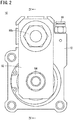
FIG. 2 is a front view of the fluid pressure cylinder inFIG. 1 ; -
FIG. 3 is a plan view of the fluid pressure cylinder inFIG. 1 ; -
FIG. 4 is a cross-sectional view of the fluid pressure cylinder inFIG. 1 taken along line IV-IV inFIG. 2 ; -
FIG. 5 is a cross-sectional view of the fluid pressure cylinder inFIG. 1 taken along line V-V inFIG. 3 ; -
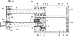
FIG. 6 is a diagram corresponding toFIG. 4 at the end of an extension stroke; -
FIG. 7 is an enlarged view of part A inFIG. 4 ; -
FIG. 8 is an enlarged view of part B inFIG. 6 ; -
FIG. 9 is a circuit diagram schematically illustrating the fluid pressure cylinder inFIG. 1 and a supply-and-discharge switching valve at the end of a retraction stroke; -
FIG. 10 is a circuit diagram schematically illustrating the fluid pressure cylinder inFIG. 1 and the supply-and-discharge switching valve during the extension stroke; -
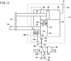
FIG. 11 is a circuit diagram schematically illustrating the fluid pressure cylinder inFIG. 1 and the supply-and-discharge switching valve at the end of the extension stroke; and -
FIG. 12 is a circuit diagram schematically illustrating the fluid pressure cylinder inFIG. 1 and the supply-and-discharge switching valve during the retraction stroke. - A preferred embodiment of a fluid pressure cylinder according to the present invention will be described in detail below with reference to the accompanying drawings. A
fluid pressure cylinder 10 is connected to a supply-and-discharge switching valve 90 to perform tasks such as positioning of workpieces. Fluid to be used includes pressurized fluid such as compressed air. - As illustrated in
FIGS. 1 ,4 , and6 , thefluid pressure cylinder 10 includes a rectangularparallelepiped cylinder body 12 with afirst cylinder hole 22 and asecond cylinder hole 38 having a smaller diameter than thefirst cylinder hole 22. Thefirst cylinder hole 22 and thesecond cylinder hole 38 extend from one longitudinal end to the other longitudinal end of thecylinder body 12 and are aligned vertically. - One end of the
first cylinder hole 22 is closed by afirst head cover 28, whereas the other end of thefirst cylinder hole 22 is closed by afirst rod cover 30. Thefirst cylinder hole 22 and afirst piston 24 slidably disposed inside thefirst cylinder hole 22 constitute afirst cylinder portion 20. Thefirst cylinder hole 22 is partitioned by thefirst piston 24 into afirst accumulation chamber 32 adjacent to the first head cover 28 (head side) and asecond accumulation chamber 34 adjacent to the first rod cover 30 (rod side). As is clear from the explanation of effects below, thefirst cylinder portion 20 functions as an advance transfer cylinder as well as an output cylinder. - One end of the
second cylinder hole 38 is closed by asecond head cover 44, whereas the other end of thesecond cylinder hole 38 is closed by asecond rod cover 46. Thesecond cylinder hole 38 and asecond piston 40 slidably disposed inside thesecond cylinder hole 38 constitute asecond cylinder portion 36. Thesecond cylinder hole 38 is partitioned by thesecond piston 40 into arelease chamber 48 adjacent to the second head cover 44 (head side) and adrive chamber 50 adjacent to the second rod cover 46 (rod side). Thesecond cylinder portion 36 functions as a return transfer cylinder. Thefirst cylinder portion 20 and thesecond cylinder portion 36 are disposed in parallel. - One end part of a
first piston rod 26 is connected to thefirst piston 24, whereas the other end part of thefirst piston rod 26 extends to the outside through thefirst rod cover 30. One end part of asecond piston rod 42 is connected to thesecond piston 40, whereas the other end part of thesecond piston rod 42 extends to the outside through thesecond rod cover 46. - The other end part of the
first piston rod 26 and the other end part of thesecond piston rod 42 are connected by arectangular connector plate 52. Specifically, with the other end part of thefirst piston rod 26 fitted in afirst insertion hole 52a created in theconnector plate 52, anoutput member 54 and afirst nut 56a disposed on either side of thefirst insertion hole 52a are screwed onto thefirst piston rod 26, thereby securing thefirst piston rod 26 to theconnector plate 52. Moreover, with the other end part of thesecond piston rod 42 fitted in asecond insertion hole 52b created in theconnector plate 52, asecond nut 56b and athird nut 56c disposed on either side of thesecond insertion hole 52b are screwed onto thesecond piston rod 42, thereby securing thesecond piston rod 42 to theconnector plate 52. - In this case, the inside diameter of the
first insertion hole 52a is larger than the outside diameter of thefirst piston rod 26, and the inside diameter of thesecond insertion hole 52b is larger than the outside diameter of thesecond piston rod 42. As a result, even if there are production errors and assembly errors, thefirst piston rod 26 and thesecond piston rod 42 can be kept parallel to each other, and sliding resistance of thefirst piston 24 and thesecond piston 40 can thus be reduced. Thefirst piston 24 and thesecond piston 40 move in an integrated manner via thefirst piston rod 26, theconnector plate 52, and thesecond piston rod 42. - In the description below, a stroke in which the
first piston 24 and thesecond piston 40 move in a direction in which thefirst piston rod 26 and thesecond piston rod 42 are pushed out of the cylinder body 12 (advance direction) is referred to as "extension stroke", whereas a stroke in which thefirst piston 24 and thesecond piston 40 move in a direction in which thefirst piston rod 26 and thesecond piston rod 42 are pulled into the cylinder body 12 (return direction) is referred to as "retraction stroke". Thefluid pressure cylinder 10 performs tasks when theoutput member 54 is pushed out integrally with thefirst piston rod 26. - As illustrated in
FIGS. 1 and3 , a supply-and-discharge port 16 and arelease port 18 are created in the top surface of thecylinder body 12. The supply-and-discharge port 16 is connected to the supply-and-discharge switching valve 90 via a pipe 94 (seeFIG. 9 ). Therelease port 18 is exposed to the atmosphere. - The
cylinder body 12 includes afirst flow path 14a connecting thesecond accumulation chamber 34 to the supply-and-discharge port 16, asecond flow path 14b connecting thedrive chamber 50 to the supply-and-discharge port 16, and athird flow path 14c connecting therelease chamber 48 to the release port 18 (seeFIG. 9 ). Acheck valve 14e is disposed on thefirst flow path 14a. Thecheck valve 14e allows fluid to flow from the supply-and-discharge switching valve 90 toward thesecond accumulation chamber 34 and blocks flow of fluid from thesecond accumulation chamber 34 toward the supply-and-discharge switching valve 90. Thecylinder body 12 further includes afourth flow path 14d connecting aradial path 80 in a discharge switching valve 74 (described below) to the supply-and-discharge port 16. Part of thefirst flow path 14a and part of thefourth flow path 14d are illustrated inFIG. 5 . - The
first piston 24 is provided with acommunication switching valve 58 for switching communication between thefirst accumulation chamber 32 and thesecond accumulation chamber 34, between enabled and disabled. Thecommunication switching valve 58 includes afirst push rod 60 protruding toward the inside of thesecond accumulation chamber 34. - As illustrated in
FIG. 7 , thefirst push rod 60 is slidably supported inside aguide hole 62 passing through thefirst piston 24 in the axial direction. Thefirst push rod 60 includes acommunication path 64 for connecting thefirst accumulation chamber 32 and thesecond accumulation chamber 34 to each other. Thecommunication path 64 includes afirst hole portion 64a passing through thefirst push rod 60 in a radial direction, and asecond hole portion 64b branching off from a point in thefirst hole portion 64a to extend toward thefirst accumulation chamber 32. Both ends of thefirst hole portion 64a are open to anannular gap 66 left between the outer circumference of thefirst push rod 60 and the wall surface of theguide hole 62, whereas the end of thesecond hole portion 64b communicates with thefirst accumulation chamber 32. When thefirst push rod 60 protrudes toward the inside of thesecond accumulation chamber 34 by a predetermined length or more, theannular gap 66 communicates with thesecond accumulation chamber 34. - The
first push rod 60 is biased in a direction of protruding toward the inside of thesecond accumulation chamber 34, by a coil spring 68 disposed between thefirst push rod 60 and aspring seat 72 secured to thefirst piston 24. Thefirst push rod 60 includes ashoulder 60a that engages with ashoulder 62a provided for theguide hole 62. This engagement limits the protruding length of thefirst push rod 60 and prevents thefirst push rod 60 from coming off. Note that thespring seat 72 has ahole 72a in the center. - Near the end of the extension stroke, the
first push rod 60 comes into contact with thefirst rod cover 30, is pushed in against the biasing force of the coil spring 68, and slides inside theguide hole 62. When thefirst push rod 60 is pushed in, a packing 70 attached to the outer circumference of thefirst push rod 60 comes into contact with the wall surface of theguide hole 62 and blocks the communication between theannular gap 66 and thesecond accumulation chamber 34. That is, thecommunication switching valve 58 blocks the communication between thefirst accumulation chamber 32 and thesecond accumulation chamber 34 near the end of the extension stroke. Thefirst push rod 60 can be pushed in to a position where thefirst push rod 60 does not protrude from the end face of thefirst piston 24. - The
first rod cover 30 is provided with thedischarge switching valve 74 that switches connection of thesecond accumulation chamber 34 to the supply-and-discharge switching valve 90 between enabled and disabled to allow pressurized fluid inside thesecond accumulation chamber 34 to be discharged. Thedischarge switching valve 74 includes asecond push rod 76 protruding toward the inside of thesecond accumulation chamber 34. When viewed in the direction along the axis of thefirst piston rod 26, thefirst push rod 60 of thecommunication switching valve 58 and thesecond push rod 76 of thedischarge switching valve 74 are separated from the axis in the opposite directions (180 degrees opposite to each other) by an equal distance. - As illustrated in
FIG. 8 , thesecond push rod 76 is slidably supported inside aguide hole 78 passing through thefirst rod cover 30 in the axial direction. Theguide hole 78 in thefirst rod cover 30 includes a small-diameter hole portion 78a adjacent to thesecond accumulation chamber 34, and a large-diameter hole portion 78b away from thesecond accumulation chamber 34. Thesecond push rod 76 includes a small-diameter shaft portion 76a fitted in the small-diameter hole portion 78a, and a large-diameter shaft portion 76b fitted in the large-diameter hole portion 78b. O-rings diameter shaft portion 76a and the large-diameter shaft portion 76b, respectively. - The
second push rod 76 is biased in a direction in which the small-diameter shaft portion 76a protrudes toward the inside of thesecond accumulation chamber 34, by acoil spring 84 disposed between thesecond push rod 76 and aspring seat 86 secured to thefirst rod cover 30. The protruding length of thesecond push rod 76 is limited by engagement of ashoulder 76c formed between the small-diameter shaft portion 76a and the large-diameter shaft portion 76b with ashoulder 78c formed between the small-diameter hole portion 78a and the large-diameter hole portion 78b. - The
first rod cover 30 includes theradial path 80 having one end opened in the outer circumferential surface of thefirst rod cover 30, and the other end opened in the large-diameter hole portion 78b. As described above, theradial path 80 communicates with thefourth flow path 14d in thecylinder body 12. Thesecond push rod 76 includes adischarge path 88 for connecting thesecond accumulation chamber 34 and theradial path 80 to each other. Thedischarge path 88 includes afirst hole portion 88a passing through the small-diameter shaft portion 76a of thesecond push rod 76 in a radial direction, and asecond hole portion 88b crossing thefirst hole portion 88a and passing through thesecond push rod 76 in the axial direction. - Near the end of the extension stroke, the
second push rod 76 comes into contact with thefirst piston 24, is pushed in against the biasing force of thecoil spring 84, and slides inside theguide hole 78. When thesecond push rod 76 is pushed in, the O-ring 82a attached to the small-diameter shaft portion 76a is separated from the wall surface of the small-diameter hole portion 78a, and thesecond accumulation chamber 34 communicates with theradial path 80 in thefirst rod cover 30 via thedischarge path 88 in thesecond push rod 76. As a result, thesecond accumulation chamber 34 is connected to the supply-and-discharge switching valve 90 via thedischarge path 88, theradial path 80, thefourth flow path 14d, and the supply-and-discharge port 16. That is, thedischarge switching valve 74 connects thesecond accumulation chamber 34 to the supply-and-discharge switching valve 90 near the end of the extension stroke. Thesecond push rod 76 can be pushed in to a position where thesecond push rod 76 does not protrude from the end face of thefirst rod cover 30. - As illustrated in
FIG. 9 , the supply-and-discharge switching valve 90 is configured as a 3-port, 2-position switching valve provided with afirst port 92a to athird port 92c and switchable between a first position and a second position. Thefirst port 92a is connected to the supply-and-discharge port 16 in thecylinder body 12 via thepipe 94. Thesecond port 92b is connected to a fluid supply source (compressor) 96. Thethird port 92c is connected to adischarge port 99 provided with asilencer 98. Thefirst port 92a is connected to thesecond port 92b when the supply-and-discharge switching valve 90 is in the first position, and thefirst port 92a is connected to thethird port 92c when the supply-and-discharge switching valve 90 is in the second position. Thepipe 94 is the only pipe required to connect thefluid pressure cylinder 10 and the supply-and-discharge switching valve 90. - The
fluid pressure cylinder 10 according to this embodiment is basically configured as above. Next, the effects thereof will be described. InFIGS. 9 to 12 , long dashed double-short dashed lines indicate the outline of thecylinder body 12. - A state where the
first piston 24 is disposed in the middle between thefirst head cover 28 and thefirst rod cover 30 as illustrated inFIG. 4 while the pressures in thefirst accumulation chamber 32, thesecond accumulation chamber 34, thedrive chamber 50, and therelease chamber 48 are equal to atmospheric pressure is defined as an initial state. - In this initial state, the supply-and-
discharge switching valve 90 is in the second position, and thus the supply-and-discharge port 16 is connected to thedischarge port 99. In addition, thefirst push rod 60 of thecommunication switching valve 58 and thesecond push rod 76 of thedischarge switching valve 74 protrude toward the inside of thesecond accumulation chamber 34. Thus, thefirst accumulation chamber 32 and thesecond accumulation chamber 34 communicate with each other, and the connection between thesecond accumulation chamber 34 and the supply-and-discharge switching valve 90 through thefourth flow path 14d is blocked. - When the supply-and-
discharge switching valve 90 is switched to the first position from the initial state, the supply-and-discharge port 16 is connected to thefluid supply source 96. Pressurized fluid from thefluid supply source 96 is supplied to thedrive chamber 50 through the supply-and-discharge port 16 and thesecond flow path 14b and to thesecond accumulation chamber 34 through the supply-and-discharge port 16 and thefirst flow path 14a on which thecheck valve 14e is disposed. When pressurized fluid is supplied to thedrive chamber 50, thesecond piston 40 is driven toward thesecond head cover 44. Thefirst piston 24 is also driven toward thefirst head cover 28 in an integrated manner with thesecond piston 40. - In contrast, pressurized fluid supplied to the
second accumulation chamber 34 is accumulated in thesecond accumulation chamber 34 and, additionally, in thefirst accumulation chamber 32 communicating with thesecond accumulation chamber 34. Thefirst piston rod 26 and thesecond piston rod 42 are pulled in to the fullest extent possible, and high-pressure fluid is accumulated in thefirst accumulation chamber 32 and thesecond accumulation chamber 34 while the pressures in the accumulation chambers are kept equal (seeFIG. 9 ). At this moment, thesecond piston 40 is in contact with thesecond head cover 44, whereas thefirst piston 24 is not in contact with thefirst head cover 28. - Next, when the supply-and-
discharge switching valve 90 is switched to the second position, the supply-and-discharge port 16 is connected to thedischarge port 99. Pressurized fluid in thedrive chamber 50 passes through thesecond flow path 14b, the supply-and-discharge port 16, and the supply-and-discharge switching valve 90 and is then discharged from thedischarge port 99 to the outside. The pressure in thedrive chamber 50 decreases to atmospheric pressure equal to the pressure in therelease chamber 48, and the driving force acting on thesecond piston 40 becomes zero. - In contrast, pressurized fluid in the
second accumulation chamber 34 is not discharged due to the effect of thecheck valve 14e. The pressure of fluid accumulated in thefirst accumulation chamber 32 and the pressure of fluid accumulated in the second accumulation chamber 34 (the pressures being equal to each other) act on thefirst piston 24 with a difference of an area corresponding to the cross-section of thefirst piston rod 26. Thus, the force generated by the fluid pressure in thefirst accumulation chamber 32 and pushing thefirst piston 24 toward thefirst rod cover 30 exceeds the force generated by the fluid pressure in thesecond accumulation chamber 34 and pushing thefirst piston 24 toward thefirst head cover 28. As a result, thefirst piston 24 is driven toward thefirst rod cover 30; that is, the extension stroke starts (seeFIG. 10 ) . - In this manner, no pressurized fluid is supplied from the
fluid supply source 96 to thefluid pressure cylinder 10 to start the extension stroke. Subsequently, near the end of the extension stroke, thefirst push rod 60 of thecommunication switching valve 58 comes into contact with thefirst rod cover 30, while thesecond push rod 76 of thedischarge switching valve 74 comes into contact with thefirst piston 24. This blocks the communication between thefirst accumulation chamber 32 and thesecond accumulation chamber 34 and connects thesecond accumulation chamber 34 to the supply-and-discharge switching valve 90 via thefourth flow path 14d (seeFIG. 11 ). - Pressurized fluid accumulated in the
second accumulation chamber 34 passes through thefourth flow path 14d, the supply-and-discharge port 16, and the supply-and-discharge switching valve 90 in the second position and is then discharged from thedischarge port 99 to the outside. Pressurized fluid accumulated in thefirst accumulation chamber 32 is prevented from flowing into thesecond accumulation chamber 34 and remains in thefirst accumulation chamber 32. As a result, the fluid pressure in thefirst accumulation chamber 32 significantly exceeds the fluid pressure in thesecond accumulation chamber 34, and thefirst piston 24 is pushed toward thefirst rod cover 30 with a large thrust. That is, thefluid pressure cylinder 10 produces the maximum force at the end of the extension stroke. - The volume of the
second accumulation chamber 34 is small near the end of the extension stroke, and only a small amount of pressurized fluid remaining in thesecond accumulation chamber 34 is discharged. Thus, the amount of pressurized fluid supplied to thesecond accumulation chamber 34 during the next retraction stroke may be as small as the amount of discharged fluid. - The
first push rod 60 brought into contact with thefirst rod cover 30 to receive the reaction force near the end of the extension stroke exerts a force on thefirst piston 24 via the coil spring 68. Moreover, thesecond push rod 76 supported by thefirst rod cover 30 via thecoil spring 84 also comes into contact with thefirst piston 24 to exert a force in the same direction as above. Since these forces act on the positions separated from the axis of thefirst piston rod 26 in the opposite directions by an equal distance, equalizing the forces by, for example, adjusting the spring constants of the coil spring 68 and thecoil spring 84 can prevent moment causing thefirst piston 24 to be inclined. - Next, when the supply-and-
discharge switching valve 90 is switched to the first position, pressurized fluid from thefluid supply source 96 passes through the supply-and-discharge switching valve 90 and is supplied to thedrive chamber 50 through the supply-and-discharge port 16 and thesecond flow path 14b and to thesecond accumulation chamber 34 through the supply-and-discharge port 16 and thefirst flow path 14a on which thecheck valve 14e is disposed. As a result, thesecond piston 40 is driven toward thesecond head cover 44 while thefirst piston 24 is driven toward thefirst head cover 28; that is, the retraction stroke starts (seeFIG. 12 ). - When the retraction stroke starts, the
first push rod 60 of thecommunication switching valve 58 protrudes from thefirst piston 24 by the biasing force of the coil spring 68, and then is separated from thefirst rod cover 30. At the same time, thesecond push rod 76 of thedischarge switching valve 74 protrudes from thefirst rod cover 30 by the biasing force of thecoil spring 84, and then is separated from thefirst piston 24. Since thefirst push rod 60 protrudes from thefirst piston 24, thefirst accumulation chamber 32 and thesecond accumulation chamber 34 communicate with each other. Since thesecond push rod 76 protrudes from thefirst rod cover 30, the connection between thesecond accumulation chamber 34 and the supply-and-discharge switching valve 90 through thefourth flow path 14d is blocked. However, pressurized fluid continues to flow from the supply-and-discharge switching valve 90 to thesecond accumulation chamber 34 through thefirst flow path 14a. - As a result, pressurized fluid from the
fluid supply source 96 is supplied to thedrive chamber 50 and supplied to and accumulated in thesecond accumulation chamber 34 via thefirst flow path 14a. The pressurized fluid is then supplied to and accumulated in thefirst accumulation chamber 32 through thecommunication switching valve 58. As the retraction stroke proceeds, thesecond piston 40 comes into contact with thesecond head cover 44. Thefirst piston rod 26 and thesecond piston rod 42 are pulled in to the fullest extent possible (seeFIG. 9 ), and high-pressure fluid is accumulated in thefirst accumulation chamber 32 and thesecond accumulation chamber 34 while the pressures in the accumulation chambers are kept equal. - From this point forward, the extension stroke performed by switching the supply-and-
discharge switching valve 90 to the second position and the retraction stroke performed by switching the supply-and-discharge switching valve 90 to the first position are repeated. Note that the difference between the cross-sectional areas of thesecond piston 40 and thesecond piston rod 42 is larger than the cross-sectional area of thefirst piston rod 26 to enable the retraction movement when pressurized fluid from thefluid supply source 96 is supplied to thedrive chamber 50 and thesecond accumulation chamber 34 communicating with thefirst accumulation chamber 32. - In accordance with the
fluid pressure cylinder 10 according to this embodiment, thefirst piston 24 in thefirst cylinder portion 20 can be advanced using the difference between the pressure-receiving areas in thefirst piston 24. That is, thefirst cylinder portion 20 can function as an advance transfer cylinder, and thus pressurized fluid may be supplied to thesecond cylinder portion 36 only when thesecond piston 40 is returned. This ultimately reduces the consumption of pressurized fluid. - Pressurized fluid from the
fluid supply source 96 can be supplied to and discharged from thesecond accumulation chamber 34 and thedrive chamber 50 through the single supply-and-discharge port 16. That is, thepipe 94 is the only pipe required to connect to thefluid pressure cylinder 10. This facilitates pipe routing. - At the end of the extension stroke, pressurized fluid accumulated in the
second accumulation chamber 34 is discharged while the communication between thefirst accumulation chamber 32 and thesecond accumulation chamber 34 is blocked. As a result, thefluid pressure cylinder 10 can exert the maximum force on workpieces. - The
first cylinder portion 20 functioning as both an output cylinder and an advance transfer cylinder and thesecond cylinder portion 36 functioning as a return transfer cylinder are combined in a parallel arrangement. Thus, the total length of thefluid pressure cylinder 10 can be significantly reduced compared with a case where a transfer cylinder and an output cylinder are arranged in series. - The supply-and-
discharge switching valve 90 connected to the supply-and-discharge port 16 can be configured as a 3-port, 2-position switching valve. As a result, the structure of the supply-and-discharge switching valve 90 can be simplified. - In this embodiment, when viewed in the direction along the axis of the
first piston rod 26, thefirst push rod 60 and thesecond push rod 76 are separated from the axis in the opposite directions by an equal distance. However, the pistons are not limited to this arrangement and may be disposed in any appropriate positions where the pistons do not come into contact with each other.
Claims (10)
- A fluid pressure cylinder (10) comprising:a first cylinder portion (20) partitioned by a first piston (24) into a first accumulation chamber (32) disposed on a head side and a second accumulation chamber (34) disposed on a rod side;a second cylinder portion (36) partitioned by a second piston (40) into a release chamber (48) disposed on the head side and a drive chamber (50) disposed on the rod side; anda supply-and-discharge port (16) through which pressurized fluid is supplied to and discharged from the second accumulation chamber and the drive chamber, wherein:the first cylinder portion and the second cylinder portion are disposed in parallel;an end of a first piston rod (26) connected to the first piston and an end of a second piston rod (42) connected to the second piston are connected to each other; andthe first piston is provided with a communication switching valve (58) configured to switch communication between the first accumulation chamber and the second accumulation chamber, between enabled and disabled.
- The fluid pressure cylinder according to claim 1, further comprising a release port (18) through which the release chamber is exposed to atmosphere.
- The fluid pressure cylinder according to claim 1, wherein the second accumulation chamber is connected to the supply-and-discharge port via a flow path (14a) provided with a check valve (14e), the check valve allowing fluid to flow from the supply-and-discharge port toward the second accumulation chamber and blocking flow of fluid from the second accumulation chamber toward the supply-and-discharge port.
- The fluid pressure cylinder according to claim 1, wherein:the end of the first piston rod passes through a rod cover (30); andthe rod cover is provided with a discharge switching valve (74) configured to discharge pressurized fluid in the second accumulation chamber.
- The fluid pressure cylinder according to claim 4, wherein:the communication switching valve includes a first push rod (60) contactable with the rod cover, the first push rod being configured to block the communication between the first accumulation chamber and the second accumulation chamber when the first push rod is brought into contact with the rod cover and pushed in; andthe discharge switching valve includes a second push rod (76) contactable with the first piston, the second push rod being configured to connect the second accumulation chamber to the supply-and-discharge port when the second push rod is brought into contact with the first piston and pushed in.
- The fluid pressure cylinder according to claim 5, wherein, when viewed in a direction along an axis of the first piston rod, the first push rod and the second push rod are separated from the axis in directions opposite to each other by an equal distance.
- The fluid pressure cylinder according to claim 1, wherein:the first piston rod and the second piston rod are connected to each other by a connector plate (52) provided with a first insertion hole (52a) and a second insertion hole (52b), the end of the first piston rod being fitted in the first insertion hole and the end of the second piston rod being fitted in the second insertion hole;the first insertion hole has an inside diameter larger than an outside diameter of the first piston rod; andthe second insertion hole has an inside diameter larger than an outside diameter of the second piston rod.
- The fluid pressure cylinder according to claim 1, wherein:the supply-and-discharge port is connected to a supply-and-discharge switching valve (90) via a pipe (94); andthe supply-and-discharge switching valve is configured as a 3-port, 2-position switching valve switchable between a first position where the supply-and-discharge port is connected to a fluid supply source (96) and a second position where the supply-and-discharge port is connected to a discharge port (99).
- A fluid pressure cylinder comprising:a first cylinder portion partitioned by a first piston into a first accumulation chamber disposed on a head side and a second accumulation chamber disposed on a rod side; anda second cylinder portion partitioned by a second piston into a release chamber disposed on the head side and a drive chamber disposed on the rod side, wherein:the first cylinder portion and the second cylinder portion are disposed in parallel;an end of a first piston rod connected to the first piston and an end of a second piston rod connected to the second piston are connected to each other;the first piston is provided with a communication switching valve configured to switch communication between the first accumulation chamber and the second accumulation chamber, between enabled and disabled; andduring a retraction stroke, pressurized fluid is supplied from a fluid supply source to the drive chamber and the second accumulation chamber while the first accumulation chamber and the second accumulation chamber communicate with each other, whereas, during an extension stroke, pressurized fluid in the drive chamber is discharged while the first accumulation chamber and the second accumulation chamber communicate with each other.
- The fluid pressure cylinder according to claim 9, wherein, at an end of the extension stroke, the communication between the first accumulation chamber and the second accumulation chamber is blocked, and pressurized fluid in the second accumulation chamber is discharged.
Applications Claiming Priority (1)
| Application Number | Priority Date | Filing Date | Title |
|---|---|---|---|
| JP2020072048A JP7395131B2 (en) | 2020-04-14 | 2020-04-14 | fluid pressure cylinder |
Publications (3)
| Publication Number | Publication Date |
|---|---|
| EP3896293A1 true EP3896293A1 (en) | 2021-10-20 |
| EP3896293B1 EP3896293B1 (en) | 2025-06-04 |
| EP3896293B8 EP3896293B8 (en) | 2025-07-09 |
Family
ID=75441744
Family Applications (1)
| Application Number | Title | Priority Date | Filing Date |
|---|---|---|---|
| EP21167555.8A Active EP3896293B8 (en) | 2020-04-14 | 2021-04-09 | Fluid pressure cylinder |
Country Status (6)
| Country | Link |
|---|---|
| US (1) | US11261885B2 (en) |
| EP (1) | EP3896293B8 (en) |
| JP (1) | JP7395131B2 (en) |
| KR (1) | KR20210127640A (en) |
| CN (1) | CN113530912B (en) |
| TW (1) | TWI890773B (en) |
Families Citing this family (3)
| Publication number | Priority date | Publication date | Assignee | Title |
|---|---|---|---|---|
| DE102019216083B4 (en) * | 2019-10-18 | 2024-11-21 | Hawe Hydraulik Se | passenger restraint device and ride passenger unit |
| US12516686B2 (en) * | 2023-06-26 | 2026-01-06 | Woodward, Inc. | Dual-parallel actuator piston interface |
| CN121251641B (en) * | 2025-10-21 | 2026-05-08 | 华东交通大学 | Closed-loop pump-controlled hydraulic circuit, adaptive flow compensation system and its control method |
Citations (4)
| Publication number | Priority date | Publication date | Assignee | Title |
|---|---|---|---|---|
| US3818801A (en) * | 1971-11-01 | 1974-06-25 | Hydron Inc | Fluid actuating mechanism having alternatively selectable fast and slow modes of operation |
| DE2544105A1 (en) * | 1975-10-02 | 1977-04-07 | Boy Kg Dr | PRESSURE-ACTUATED DRIVE FOR CLOSING UNITS OF INJECTION MOLDING MACHINES |
| JP5048696B2 (en) | 2009-03-02 | 2012-10-17 | Ckd株式会社 | Air cylinder |
| WO2020054322A1 (en) * | 2018-09-13 | 2020-03-19 | Smc株式会社 | Hydraulic cylinder |
Family Cites Families (20)
| Publication number | Priority date | Publication date | Assignee | Title |
|---|---|---|---|---|
| JPS62155204U (en) * | 1986-03-26 | 1987-10-02 | ||
| IN168838B (en) * | 1987-02-28 | 1991-06-22 | Nissei Plastics Ind Co | |
| JP2594316Y2 (en) * | 1991-11-29 | 1999-04-26 | エヌオーケー株式会社 | Three position stop actuator |
| US5263402A (en) * | 1992-05-26 | 1993-11-23 | Nathan Gottlieb | Lift/slider apparatus |
| JPH07158611A (en) * | 1993-10-12 | 1995-06-20 | Smc Corp | Buffer mechanism for slide actuator |
| WO1997002132A1 (en) * | 1995-07-06 | 1997-01-23 | Komatsu Ltd. | High-speed and high-load cylinder device and method for controlling the same |
| JPH1047311A (en) * | 1996-08-05 | 1998-02-17 | Koganei Corp | Fluid pressure cylinder |
| TW451031B (en) * | 1999-10-01 | 2001-08-21 | Smc Corp | Linear actuator with air buffer mechanism |
| JP3462461B2 (en) * | 1999-10-01 | 2003-11-05 | Smc株式会社 | Linear actuator with air cushion mechanism |
| DE102006041707B4 (en) * | 2006-05-10 | 2009-01-02 | Tünkers Maschinenbau Gmbh | Piston-cylinder unit (working cylinder) for clamping, and / or pressing, and / or joining, and / or punching, and / or embossing, and / or punching and / or welding, for example, with the interposition of a toggle joint arrangement |
| JP4943126B2 (en) * | 2006-11-30 | 2012-05-30 | 株式会社キッツ | Emergency shut-off actuator with test moving mechanism |
| AT509239B1 (en) * | 2009-12-17 | 2013-03-15 | Trumpf Maschinen Austria Gmbh | DRIVE DEVICE FOR A BEND PRESS |
| CN102454654A (en) * | 2010-10-28 | 2012-05-16 | 鸿富锦精密工业(深圳)有限公司 | Air cylinder |
| JP5426037B2 (en) * | 2010-11-25 | 2014-02-26 | 株式会社島津製作所 | Hydraulic cylinder system |
| JP6240983B2 (en) * | 2014-04-01 | 2017-12-06 | Smc株式会社 | Fluid pressure cylinder |
| EP3283244B1 (en) * | 2015-03-19 | 2020-12-02 | Howmet Aerospace Inc. | Dual piston close clearance fastening tool |
| JP3207583U (en) * | 2016-09-07 | 2016-11-17 | Smc株式会社 | Fluid pressure cylinder |
| JP6673551B2 (en) * | 2016-09-21 | 2020-03-25 | Smc株式会社 | Fluid pressure cylinder |
| JP6673554B2 (en) * | 2017-04-28 | 2020-03-25 | Smc株式会社 | Pressure intensifier and cylinder device having the same |
| KR101926128B1 (en) * | 2018-07-10 | 2018-12-06 | 장영학 | High-efficiency connector with adjustable slow-action point Pneumatic cylinder unit for inspection device |
-
2020
- 2020-04-14 JP JP2020072048A patent/JP7395131B2/en active Active
-
2021
- 2021-04-09 EP EP21167555.8A patent/EP3896293B8/en active Active
- 2021-04-12 US US17/227,499 patent/US11261885B2/en active Active
- 2021-04-13 CN CN202110394171.7A patent/CN113530912B/en active Active
- 2021-04-13 TW TW110113235A patent/TWI890773B/en active
- 2021-04-14 KR KR1020210048635A patent/KR20210127640A/en active Pending
Patent Citations (4)
| Publication number | Priority date | Publication date | Assignee | Title |
|---|---|---|---|---|
| US3818801A (en) * | 1971-11-01 | 1974-06-25 | Hydron Inc | Fluid actuating mechanism having alternatively selectable fast and slow modes of operation |
| DE2544105A1 (en) * | 1975-10-02 | 1977-04-07 | Boy Kg Dr | PRESSURE-ACTUATED DRIVE FOR CLOSING UNITS OF INJECTION MOLDING MACHINES |
| JP5048696B2 (en) | 2009-03-02 | 2012-10-17 | Ckd株式会社 | Air cylinder |
| WO2020054322A1 (en) * | 2018-09-13 | 2020-03-19 | Smc株式会社 | Hydraulic cylinder |
Also Published As
| Publication number | Publication date |
|---|---|
| EP3896293B8 (en) | 2025-07-09 |
| JP2021169824A (en) | 2021-10-28 |
| US11261885B2 (en) | 2022-03-01 |
| EP3896293B1 (en) | 2025-06-04 |
| US20210317850A1 (en) | 2021-10-14 |
| TW202202741A (en) | 2022-01-16 |
| KR20210127640A (en) | 2021-10-22 |
| JP7395131B2 (en) | 2023-12-11 |
| CN113530912A (en) | 2021-10-22 |
| TWI890773B (en) | 2025-07-21 |
| CN113530912B (en) | 2025-11-14 |
Similar Documents
| Publication | Publication Date | Title |
|---|---|---|
| EP3896293B1 (en) | Fluid pressure cylinder | |
| EP0399102B1 (en) | Hydraulic-pneumatic cylinder device | |
| CN101421521B (en) | Elbow-bar clamping device | |
| KR100498878B1 (en) | Workpiece high-speed pressurizing method and mechanism by using cylinder with cushioning mechanism | |
| EP1048854A2 (en) | Servo-driving pilot-type solenoid valve | |
| CN109790859B (en) | fluid pressure cylinder | |
| US10895269B2 (en) | Double acting hydraulic pressure intensifier | |
| TW343168B (en) | A pneumatic actuator device | |
| JPH02218873A (en) | Pumping apparatus actuated by compressed air | |
| CN110573750A (en) | Supercharging device and cylinder device provided with the supercharging device | |
| WO2007117099A1 (en) | Hydraulic pressure transformers | |
| KR100668409B1 (en) | Marine Spool Valve | |
| CN113446273B (en) | Supercharging output stabilization device | |
| TWI686544B (en) | Fluid circuit for air cylinder | |
| CN213392966U (en) | Mechanical locking hydraulic cylinder | |
| JP3373905B2 (en) | Pilot operated switching valve | |
| KR20050045086A (en) | Pressure intensifying cylinder | |
| JPH0222188Y2 (en) | ||
| KR20040061763A (en) | Pressure Intensifying Cylinder | |
| CN121916214A (en) | Stacked hydraulic tool layout | |
| JP2023028741A (en) | Air-hydro booster, clamp system, robot arm, and processing method | |
| JP2005030529A (en) | Marine spool valve | |
| GB2311331A (en) | Hydraulic ram booster | |
| JPH0219664A (en) | Hydraulic pump unit by means of pressure gas | |
| WO2019188127A1 (en) | Fluid circuit for air cylinder |
Legal Events
| Date | Code | Title | Description |
|---|---|---|---|
| PUAI | Public reference made under article 153(3) epc to a published international application that has entered the european phase |
Free format text: ORIGINAL CODE: 0009012 |
|
| STAA | Information on the status of an ep patent application or granted ep patent |
Free format text: STATUS: THE APPLICATION HAS BEEN PUBLISHED |
|
| AK | Designated contracting states |
Kind code of ref document: A1 Designated state(s): AL AT BE BG CH CY CZ DE DK EE ES FI FR GB GR HR HU IE IS IT LI LT LU LV MC MK MT NL NO PL PT RO RS SE SI SK SM TR |
|
| B565 | Issuance of search results under rule 164(2) epc |
Effective date: 20210812 |
|
| STAA | Information on the status of an ep patent application or granted ep patent |
Free format text: STATUS: REQUEST FOR EXAMINATION WAS MADE |
|
| 17P | Request for examination filed |
Effective date: 20220412 |
|
| RBV | Designated contracting states (corrected) |
Designated state(s): AL AT BE BG CH CY CZ DE DK EE ES FI FR GB GR HR HU IE IS IT LI LT LU LV MC MK MT NL NO PL PT RO RS SE SI SK SM TR |
|
| GRAP | Despatch of communication of intention to grant a patent |
Free format text: ORIGINAL CODE: EPIDOSNIGR1 |
|
| STAA | Information on the status of an ep patent application or granted ep patent |
Free format text: STATUS: GRANT OF PATENT IS INTENDED |
|
| INTG | Intention to grant announced |
Effective date: 20241004 |
|
| GRAJ | Information related to disapproval of communication of intention to grant by the applicant or resumption of examination proceedings by the epo deleted |
Free format text: ORIGINAL CODE: EPIDOSDIGR1 |
|
| STAA | Information on the status of an ep patent application or granted ep patent |
Free format text: STATUS: REQUEST FOR EXAMINATION WAS MADE |
|
| GRAS | Grant fee paid |
Free format text: ORIGINAL CODE: EPIDOSNIGR3 |
|
| STAA | Information on the status of an ep patent application or granted ep patent |
Free format text: STATUS: GRANT OF PATENT IS INTENDED |
|
| GRAP | Despatch of communication of intention to grant a patent |
Free format text: ORIGINAL CODE: EPIDOSNIGR1 |
|
| INTC | Intention to grant announced (deleted) | ||
| INTG | Intention to grant announced |
Effective date: 20250227 |
|
| GRAA | (expected) grant |
Free format text: ORIGINAL CODE: 0009210 |
|
| STAA | Information on the status of an ep patent application or granted ep patent |
Free format text: STATUS: THE PATENT HAS BEEN GRANTED |
|
| AK | Designated contracting states |
Kind code of ref document: B1 Designated state(s): AL AT BE BG CH CY CZ DE DK EE ES FI FR GB GR HR HU IE IS IT LI LT LU LV MC MK MT NL NO PL PT RO RS SE SI SK SM TR |
|
| REG | Reference to a national code |
Ref country code: GB Ref legal event code: FG4D |
|
| RAP4 | Party data changed (patent owner data changed or rights of a patent transferred) |
Owner name: SMC CORPORATION |
|
| REG | Reference to a national code |
Ref country code: CH Ref legal event code: PK Free format text: BERICHTIGUNG B8 Ref country code: CH Ref legal event code: EP |
|
| REG | Reference to a national code |
Ref country code: DE Ref legal event code: R096 Ref document number: 602021031598 Country of ref document: DE |
|
| REG | Reference to a national code |
Ref country code: IE Ref legal event code: FG4D |
|
| REG | Reference to a national code |
Ref country code: NL Ref legal event code: MP Effective date: 20250604 |
|
| PG25 | Lapsed in a contracting state [announced via postgrant information from national office to epo] |
Ref country code: ES Free format text: LAPSE BECAUSE OF FAILURE TO SUBMIT A TRANSLATION OF THE DESCRIPTION OR TO PAY THE FEE WITHIN THE PRESCRIBED TIME-LIMIT Effective date: 20250604 Ref country code: FI Free format text: LAPSE BECAUSE OF FAILURE TO SUBMIT A TRANSLATION OF THE DESCRIPTION OR TO PAY THE FEE WITHIN THE PRESCRIBED TIME-LIMIT Effective date: 20250604 |
|
| REG | Reference to a national code |
Ref country code: LT Ref legal event code: MG9D |
|
| PG25 | Lapsed in a contracting state [announced via postgrant information from national office to epo] |
Ref country code: GR Free format text: LAPSE BECAUSE OF FAILURE TO SUBMIT A TRANSLATION OF THE DESCRIPTION OR TO PAY THE FEE WITHIN THE PRESCRIBED TIME-LIMIT Effective date: 20250905 Ref country code: NO Free format text: LAPSE BECAUSE OF FAILURE TO SUBMIT A TRANSLATION OF THE DESCRIPTION OR TO PAY THE FEE WITHIN THE PRESCRIBED TIME-LIMIT Effective date: 20250904 |
|
| PG25 | Lapsed in a contracting state [announced via postgrant information from national office to epo] |
Ref country code: PL Free format text: LAPSE BECAUSE OF FAILURE TO SUBMIT A TRANSLATION OF THE DESCRIPTION OR TO PAY THE FEE WITHIN THE PRESCRIBED TIME-LIMIT Effective date: 20250604 |
|
| PG25 | Lapsed in a contracting state [announced via postgrant information from national office to epo] |
Ref country code: BG Free format text: LAPSE BECAUSE OF FAILURE TO SUBMIT A TRANSLATION OF THE DESCRIPTION OR TO PAY THE FEE WITHIN THE PRESCRIBED TIME-LIMIT Effective date: 20250604 |
|
| PG25 | Lapsed in a contracting state [announced via postgrant information from national office to epo] |
Ref country code: HR Free format text: LAPSE BECAUSE OF FAILURE TO SUBMIT A TRANSLATION OF THE DESCRIPTION OR TO PAY THE FEE WITHIN THE PRESCRIBED TIME-LIMIT Effective date: 20250604 |
|
| PG25 | Lapsed in a contracting state [announced via postgrant information from national office to epo] |
Ref country code: RS Free format text: LAPSE BECAUSE OF FAILURE TO SUBMIT A TRANSLATION OF THE DESCRIPTION OR TO PAY THE FEE WITHIN THE PRESCRIBED TIME-LIMIT Effective date: 20250904 |
|
| PG25 | Lapsed in a contracting state [announced via postgrant information from national office to epo] |
Ref country code: LV Free format text: LAPSE BECAUSE OF FAILURE TO SUBMIT A TRANSLATION OF THE DESCRIPTION OR TO PAY THE FEE WITHIN THE PRESCRIBED TIME-LIMIT Effective date: 20250604 |
|
| PG25 | Lapsed in a contracting state [announced via postgrant information from national office to epo] |
Ref country code: NL Free format text: LAPSE BECAUSE OF FAILURE TO SUBMIT A TRANSLATION OF THE DESCRIPTION OR TO PAY THE FEE WITHIN THE PRESCRIBED TIME-LIMIT Effective date: 20250604 |
|
| PG25 | Lapsed in a contracting state [announced via postgrant information from national office to epo] |
Ref country code: PT Free format text: LAPSE BECAUSE OF FAILURE TO SUBMIT A TRANSLATION OF THE DESCRIPTION OR TO PAY THE FEE WITHIN THE PRESCRIBED TIME-LIMIT Effective date: 20251006 |
|
| REG | Reference to a national code |
Ref country code: AT Ref legal event code: MK05 Ref document number: 1800569 Country of ref document: AT Kind code of ref document: T Effective date: 20250604 |
|
| PG25 | Lapsed in a contracting state [announced via postgrant information from national office to epo] |
Ref country code: IS Free format text: LAPSE BECAUSE OF FAILURE TO SUBMIT A TRANSLATION OF THE DESCRIPTION OR TO PAY THE FEE WITHIN THE PRESCRIBED TIME-LIMIT Effective date: 20251004 |
|
| PG25 | Lapsed in a contracting state [announced via postgrant information from national office to epo] |
Ref country code: SM Free format text: LAPSE BECAUSE OF FAILURE TO SUBMIT A TRANSLATION OF THE DESCRIPTION OR TO PAY THE FEE WITHIN THE PRESCRIBED TIME-LIMIT Effective date: 20250604 Ref country code: AT Free format text: LAPSE BECAUSE OF FAILURE TO SUBMIT A TRANSLATION OF THE DESCRIPTION OR TO PAY THE FEE WITHIN THE PRESCRIBED TIME-LIMIT Effective date: 20250604 |
|
| PG25 | Lapsed in a contracting state [announced via postgrant information from national office to epo] |
Ref country code: CZ Free format text: LAPSE BECAUSE OF FAILURE TO SUBMIT A TRANSLATION OF THE DESCRIPTION OR TO PAY THE FEE WITHIN THE PRESCRIBED TIME-LIMIT Effective date: 20250604 |
|
| PG25 | Lapsed in a contracting state [announced via postgrant information from national office to epo] |
Ref country code: RO Free format text: LAPSE BECAUSE OF FAILURE TO SUBMIT A TRANSLATION OF THE DESCRIPTION OR TO PAY THE FEE WITHIN THE PRESCRIBED TIME-LIMIT Effective date: 20250604 Ref country code: SK Free format text: LAPSE BECAUSE OF FAILURE TO SUBMIT A TRANSLATION OF THE DESCRIPTION OR TO PAY THE FEE WITHIN THE PRESCRIBED TIME-LIMIT Effective date: 20250604 |
|
| PG25 | Lapsed in a contracting state [announced via postgrant information from national office to epo] |
Ref country code: IT Free format text: LAPSE BECAUSE OF FAILURE TO SUBMIT A TRANSLATION OF THE DESCRIPTION OR TO PAY THE FEE WITHIN THE PRESCRIBED TIME-LIMIT Effective date: 20250604 |
|
| REG | Reference to a national code |
Ref country code: DE Ref legal event code: R097 Ref document number: 602021031598 Country of ref document: DE |
|
| PLBE | No opposition filed within time limit |
Free format text: ORIGINAL CODE: 0009261 |
|
| STAA | Information on the status of an ep patent application or granted ep patent |
Free format text: STATUS: NO OPPOSITION FILED WITHIN TIME LIMIT |
|
| PG25 | Lapsed in a contracting state [announced via postgrant information from national office to epo] |
Ref country code: DK Free format text: LAPSE BECAUSE OF FAILURE TO SUBMIT A TRANSLATION OF THE DESCRIPTION OR TO PAY THE FEE WITHIN THE PRESCRIBED TIME-LIMIT Effective date: 20250604 |
|
| REG | Reference to a national code |
Ref country code: CH Ref legal event code: L10 Free format text: ST27 STATUS EVENT CODE: U-0-0-L10-L00 (AS PROVIDED BY THE NATIONAL OFFICE) Effective date: 20260416 |
|
| 26N | No opposition filed |
Effective date: 20260305 |