EP3896255A1 - Multi-material vane for a gas turbine engine - Google Patents
Multi-material vane for a gas turbine engine Download PDFInfo
- Publication number
- EP3896255A1 EP3896255A1 EP21169000.3A EP21169000A EP3896255A1 EP 3896255 A1 EP3896255 A1 EP 3896255A1 EP 21169000 A EP21169000 A EP 21169000A EP 3896255 A1 EP3896255 A1 EP 3896255A1
- Authority
- EP
- European Patent Office
- Prior art keywords
- airfoil
- section
- vane
- side section
- base section
- Prior art date
- Legal status (The legal status is an assumption and is not a legal conclusion. Google has not performed a legal analysis and makes no representation as to the accuracy of the status listed.)
- Pending
Links
- 239000000463 material Substances 0.000 title claims abstract description 17
- 239000007769 metal material Substances 0.000 claims description 28
- 229910052755 nonmetal Inorganic materials 0.000 claims description 22
- 239000003733 fiber-reinforced composite Substances 0.000 claims description 4
- 230000007704 transition Effects 0.000 description 7
- PXHVJJICTQNCMI-UHFFFAOYSA-N Nickel Chemical compound [Ni] PXHVJJICTQNCMI-UHFFFAOYSA-N 0.000 description 6
- 239000002184 metal Substances 0.000 description 6
- 229910052751 metal Inorganic materials 0.000 description 6
- 239000010936 titanium Substances 0.000 description 4
- 238000002485 combustion reaction Methods 0.000 description 3
- 238000004519 manufacturing process Methods 0.000 description 3
- 229910000831 Steel Inorganic materials 0.000 description 2
- RTAQQCXQSZGOHL-UHFFFAOYSA-N Titanium Chemical compound [Ti] RTAQQCXQSZGOHL-UHFFFAOYSA-N 0.000 description 2
- 239000000956 alloy Substances 0.000 description 2
- 229910045601 alloy Inorganic materials 0.000 description 2
- 229910052782 aluminium Inorganic materials 0.000 description 2
- XAGFODPZIPBFFR-UHFFFAOYSA-N aluminium Chemical compound [Al] XAGFODPZIPBFFR-UHFFFAOYSA-N 0.000 description 2
- -1 but not limited to Substances 0.000 description 2
- 239000002131 composite material Substances 0.000 description 2
- 239000000446 fuel Substances 0.000 description 2
- 239000011159 matrix material Substances 0.000 description 2
- 239000000203 mixture Substances 0.000 description 2
- 229910052759 nickel Inorganic materials 0.000 description 2
- 230000002093 peripheral effect Effects 0.000 description 2
- 239000010959 steel Substances 0.000 description 2
- 229910052719 titanium Inorganic materials 0.000 description 2
- 238000011144 upstream manufacturing Methods 0.000 description 2
- 229920000049 Carbon (fiber) Polymers 0.000 description 1
- 229910052799 carbon Inorganic materials 0.000 description 1
- 239000004917 carbon fiber Substances 0.000 description 1
- 230000006835 compression Effects 0.000 description 1
- 238000007906 compression Methods 0.000 description 1
- 239000011152 fibreglass Substances 0.000 description 1
- 239000002905 metal composite material Substances 0.000 description 1
- VNWKTOKETHGBQD-UHFFFAOYSA-N methane Chemical compound C VNWKTOKETHGBQD-UHFFFAOYSA-N 0.000 description 1
- 238000000034 method Methods 0.000 description 1
- 229920000642 polymer Polymers 0.000 description 1
- 238000005096 rolling process Methods 0.000 description 1
- 238000000926 separation method Methods 0.000 description 1
- 239000007787 solid Substances 0.000 description 1
- 229920001169 thermoplastic Polymers 0.000 description 1
- 229920001187 thermosetting polymer Polymers 0.000 description 1
- 239000004416 thermosoftening plastic Substances 0.000 description 1
Images


Classifications
-
- F—MECHANICAL ENGINEERING; LIGHTING; HEATING; WEAPONS; BLASTING
- F01—MACHINES OR ENGINES IN GENERAL; ENGINE PLANTS IN GENERAL; STEAM ENGINES
- F01D—NON-POSITIVE DISPLACEMENT MACHINES OR ENGINES, e.g. STEAM TURBINES
- F01D9/00—Stators
- F01D9/02—Nozzles; Nozzle boxes; Stator blades; Guide conduits, e.g. individual nozzles
-
- F—MECHANICAL ENGINEERING; LIGHTING; HEATING; WEAPONS; BLASTING
- F01—MACHINES OR ENGINES IN GENERAL; ENGINE PLANTS IN GENERAL; STEAM ENGINES
- F01D—NON-POSITIVE DISPLACEMENT MACHINES OR ENGINES, e.g. STEAM TURBINES
- F01D5/00—Blades; Blade-carrying members; Heating, heat-insulating, cooling or antivibration means on the blades or the members
- F01D5/12—Blades
- F01D5/14—Form or construction
- F01D5/147—Construction, i.e. structural features, e.g. of weight-saving hollow blades
-
- F—MECHANICAL ENGINEERING; LIGHTING; HEATING; WEAPONS; BLASTING
- F01—MACHINES OR ENGINES IN GENERAL; ENGINE PLANTS IN GENERAL; STEAM ENGINES
- F01D—NON-POSITIVE DISPLACEMENT MACHINES OR ENGINES, e.g. STEAM TURBINES
- F01D5/00—Blades; Blade-carrying members; Heating, heat-insulating, cooling or antivibration means on the blades or the members
- F01D5/12—Blades
- F01D5/28—Selecting particular materials; Particular measures relating thereto; Measures against erosion or corrosion
- F01D5/282—Selecting composite materials, e.g. blades with reinforcing filaments
-
- F—MECHANICAL ENGINEERING; LIGHTING; HEATING; WEAPONS; BLASTING
- F05—INDEXING SCHEMES RELATING TO ENGINES OR PUMPS IN VARIOUS SUBCLASSES OF CLASSES F01-F04
- F05D—INDEXING SCHEME FOR ASPECTS RELATING TO NON-POSITIVE-DISPLACEMENT MACHINES OR ENGINES, GAS-TURBINES OR JET-PROPULSION PLANTS
- F05D2240/00—Components
- F05D2240/10—Stators
- F05D2240/12—Fluid guiding means, e.g. vanes
- F05D2240/121—Fluid guiding means, e.g. vanes related to the leading edge of a stator vane
-
- F—MECHANICAL ENGINEERING; LIGHTING; HEATING; WEAPONS; BLASTING
- F05—INDEXING SCHEMES RELATING TO ENGINES OR PUMPS IN VARIOUS SUBCLASSES OF CLASSES F01-F04
- F05D—INDEXING SCHEME FOR ASPECTS RELATING TO NON-POSITIVE-DISPLACEMENT MACHINES OR ENGINES, GAS-TURBINES OR JET-PROPULSION PLANTS
- F05D2240/00—Components
- F05D2240/10—Stators
- F05D2240/12—Fluid guiding means, e.g. vanes
- F05D2240/122—Fluid guiding means, e.g. vanes related to the trailing edge of a stator vane
-
- F—MECHANICAL ENGINEERING; LIGHTING; HEATING; WEAPONS; BLASTING
- F05—INDEXING SCHEMES RELATING TO ENGINES OR PUMPS IN VARIOUS SUBCLASSES OF CLASSES F01-F04
- F05D—INDEXING SCHEME FOR ASPECTS RELATING TO NON-POSITIVE-DISPLACEMENT MACHINES OR ENGINES, GAS-TURBINES OR JET-PROPULSION PLANTS
- F05D2240/00—Components
- F05D2240/10—Stators
- F05D2240/12—Fluid guiding means, e.g. vanes
- F05D2240/126—Baffles or ribs
-
- F—MECHANICAL ENGINEERING; LIGHTING; HEATING; WEAPONS; BLASTING
- F05—INDEXING SCHEMES RELATING TO ENGINES OR PUMPS IN VARIOUS SUBCLASSES OF CLASSES F01-F04
- F05D—INDEXING SCHEME FOR ASPECTS RELATING TO NON-POSITIVE-DISPLACEMENT MACHINES OR ENGINES, GAS-TURBINES OR JET-PROPULSION PLANTS
- F05D2300/00—Materials; Properties thereof
- F05D2300/10—Metals, alloys or intermetallic compounds
-
- F—MECHANICAL ENGINEERING; LIGHTING; HEATING; WEAPONS; BLASTING
- F05—INDEXING SCHEMES RELATING TO ENGINES OR PUMPS IN VARIOUS SUBCLASSES OF CLASSES F01-F04
- F05D—INDEXING SCHEME FOR ASPECTS RELATING TO NON-POSITIVE-DISPLACEMENT MACHINES OR ENGINES, GAS-TURBINES OR JET-PROPULSION PLANTS
- F05D2300/00—Materials; Properties thereof
- F05D2300/60—Properties or characteristics given to material by treatment or manufacturing
- F05D2300/603—Composites; e.g. fibre-reinforced
-
- Y—GENERAL TAGGING OF NEW TECHNOLOGICAL DEVELOPMENTS; GENERAL TAGGING OF CROSS-SECTIONAL TECHNOLOGIES SPANNING OVER SEVERAL SECTIONS OF THE IPC; TECHNICAL SUBJECTS COVERED BY FORMER USPC CROSS-REFERENCE ART COLLECTIONS [XRACs] AND DIGESTS
- Y02—TECHNOLOGIES OR APPLICATIONS FOR MITIGATION OR ADAPTATION AGAINST CLIMATE CHANGE
- Y02T—CLIMATE CHANGE MITIGATION TECHNOLOGIES RELATED TO TRANSPORTATION
- Y02T50/00—Aeronautics or air transport
- Y02T50/60—Efficient propulsion technologies, e.g. for aircraft
Definitions
- This disclosure (invention) relates generally to a gas turbine engine and, more particularly, to a vane / vane assembly for a gas turbine engine.
- vanes such as structural guide vanes for a gas turbine engine
- these known vanes have various benefits, there is still room in the art for improvement.
- a light weight structural guide vane which is relatively simple to manufacture.
- a vane for a gas turbine engine.
- This vane includes an airfoil extending along a camber line between a leading edge and a trailing edge.
- the airfoil extends along a span line between an inner end and an outer end.
- the airfoil extends laterally between a first side and a second side.
- the airfoil includes a base section, a first side section, a second side section and a sheath.
- the base section extends along the span line between the inner end and the outer end.
- the base section is laterally between the first side section and the second side section.
- the base section is configured from or otherwise includes metal material.
- the first side section is connected to the base section and partially forms the first side of the airfoil.
- the first side section is configured from or otherwise includes first non-metal material.
- the second side section is connected to the base section and partially forms the second side of the airfoil.
- the second side section is configured from or otherwise includes second non-metal material.
- the sheath at least partially forms an edge of the airfoil. The edge may be the leading edge or the trailing edge of the airfoil.
- another vane for a gas turbine engine.
- This vane includes an airfoil extending longitudinally between a first edge and a second edge.
- the airfoil extends spanwise between an inner end and an outer end.
- the airfoil extends laterally between a first side and a second side.
- the airfoil includes a base section, a first side section, a second side section and a sheath.
- the base section is laterally between the first side section and the second side section.
- the base section is configured from or otherwise includes metal material.
- the first side section is connected to the base section and partially forms the first side of the airfoil.
- the first side section is configured from or otherwise includes first non-metal material.
- the second side section is connected to the base section and partially forms the second side of the airfoil.
- the second side section is configured from or otherwise includes second non-metal material.
- the sheath partially forms an exterior surface of the airfoil and is attached to the base section
- still another vane for a gas turbine engine.
- This vane includes an inner platform, an outer platform and an airfoil.
- the airfoil extends longitudinally between a first edge and a second edge.
- the airfoil extends spanwise between the inner platform and the outer platform.
- the airfoil extends laterally between a first side and a second side.
- the airfoil includes a base section, a first side section and a sheath.
- the base section extends spanwise between and is formed integrally with the inner platform and the outer platform.
- the base section is configured from or otherwise includes metal material.
- the first side section is connected to the base section and partially forms the first side of the airfoil.
- the first side section is configured from or otherwise includes first non-metal material.
- the sheath at least partially forms the first edge of the airfoil.
- the airfoil may also include a second side section.
- the base may be laterally between and may provide a divider between the first side section and the second side section.
- the second side section may be connected to the base section and may partially form the second side of the airfoil.
- the second side section may be configured from or otherwise include second non-metal material.
- the sheath may completely form the edge of the airfoil.
- the edge of the airfoil may be the leading edge of the airfoil.
- the edge of the airfoil may be the trailing edge of the airfoil.
- the edge of the airfoil may be the leading edge of the airfoil.
- the airfoil may also include a second sheath at least partially forming the trailing edge of the airfoil.
- the sheath may be bonded to the base section, the first side section and the second side section.
- the airfoil may have a span length extending along the span line between the inner end and the outer end of the airfoil.
- An end-to-end length of the first side section along the span line may be less than the span length.
- the airfoil may have a span length extending along the span line between the inner end and the outer end of the airfoil.
- An end-to-end length of the second side section along the span line may be less than the span length.
- the airfoil may have an inner end portion at the inner end.
- the airfoil may have an outer end portion at the outer end.
- the airfoil may have an intermediate portion extending along the span line between the inner end portion and the outer end portion. At least the base section, the first side section, the second side section and the sheath may collectively form the intermediate portion. At least the base section and the sheath may collectively form the inner end portion and/or the outer end portion.
- the first side section may not form the inner end portion and/or the outer end portion.
- the second side section may not form the inner end portion and/or the outer end portion.
- the first side section may abut against the base section in a spanwise direction.
- the second side section may abut against the base section in the spanwise direction.
- the base section may extend along the camber line through a channel which is laterally between the first side section and the second side section.
- the base section may have a first portion and a second portion aligned along the camber line.
- the first portion may be between the second portion and one of the inner end and the outer end along the span line.
- the first portion may have a first lateral thickness.
- the second portion may have a second lateral thickness that is less than the first lateral thickness.
- the first side section and/or the second side section may overlap and may be connected to the first portion and the second portion.
- the vane may also include an inner platform.
- the base section may extend along the span line to and/or may be formed integrally with the inner platform.
- the vane may also include an outer platform.
- the base section may extend along the span line to and/or may be formed integrally with the outer platform.
- the base section may be configured as an aperture free body at least between the first side section and the second side section.
- the first non-metal material may be configured from or otherwise include fiber-reinforced composite material.
- the second non-metal material may be configured from or otherwise include fiber-reinforced composite material.
- the vane may be configured as a structural guide vane of the gas turbine engine.
- the present invention may include any one or more of the individual features disclosed above and/or below alone or in any combination thereof.
- FIGS. 1 and 2 illustrate a multi-material vane 20 (e.g., a metal-composite vane) for a gas turbine engine.
- This vane 20 may be configured as a structural guide vane; e.g., a structural exit guide vane.
- the vane 20 may extend between and be structurally tied to an inner structure 22 of the gas turbine engine and an outer structure 24 of the gas turbine engine. With such a configuration, the vane 20 is configured to transfer loads between the inner structure 22 and the outer structure 24.
- the vane 20 may also or alternatively be configured to direct flow within a flowpath 26 (e.g., a bypass flowpath) of the gas turbine engine.
- the vane 20 of the present disclosure is not limited to such an exemplary vane configuration or arrangement within the gas turbine engine.
- the vane 20 includes a vane airfoil 28, a vane inner platform 29 (e.g., a shroud segment) and a vane outer platform 30 (e.g., a shroud segment).
- the vane 20 of FIG. 1 also include a vane inner mount 31 and a vane outer mount 32.
- the vane 20 may alternatively be configured without one or more of the vane components 29-32 and/or include one or more additional vane components.
- the inner platform 29 and/or the outer platform 30 may be configured discrete from the vane 20.
- the vane airfoil 28 of FIG. 1 extends spanwise along a span line 34 between an airfoil inner end 36 and an airfoil outer end 38, where the airfoil outer end 38 is positioned radially outboard of the airfoil inner end 36.
- the vane airfoil 28 extends longitudinally along a camber line 40 between an (e.g., forward, upstream) airfoil leading edge 42 and an (e.g., aft, downstream) airfoil trailing edge 44.
- the vane airfoil 28 extends laterally (e.g., widthwise) between an (e.g., pressure, concave) airfoil first side 46 and an (e.g., suction, convex) airfoil second side 48.
- an (e.g., pressure, concave) airfoil first side 46 and an (e.g., suction, convex) airfoil second side 48.
- each of these vane airfoil elements 42, 44, 46 and 48 extends between and to the airfoil inner end 36 and the airfoil outer end 38.
- the vane airfoil 28 has an airfoil inner end portion 50, an airfoil outer end portion 51 and an airfoil intermediate portion 52.
- Each of these airfoil portions 50-52 defines a respective part of the airfoil elements 42, 44, 46 and 48; see also FIG. 2 .
- the intermediate portion 52 extends spanwise between and to the inner end portion 50 and the outer end portion 51.
- the inner end portion 50 is arranged at the airfoil inner end 36, and is connected to the vane inner platform 29.
- the outer end portion 51 is arranged at the airfoil outer end 38, and is connected to the vane outer platform 30.
- the vane inner platform 29 is configured to form an inner peripheral portion of the flowpath 26.
- the vane outer platform 30 is positioned radially outboard of the vane inner platform 29.
- the vane outer platform 30 is configured to form an outer peripheral portion of the flowpath 26.
- the vane inner mount 31 is configured to attach and structurally tie the vane 20 to the inner structure 22.
- the vane outer mount 32 is configured to attach and structurally tie the vane 20 to the outer structure 24. Referring to FIG. 1 , the vane inner mount 31 is positioned radially inboard of and connected to the vane inner platform 29.
- the vane outer mount 32 is position radially outboard of and connected to the vane outer platform 30.
- the vane airfoil 28 of FIGS. 1 and 2 is configured as a multi-material (e.g., bi-material) airfoil; e.g., a metallic-composite hybrid airfoil.
- the vane airfoil 28 of FIGS. 1 and 2 includes an airfoil base section 54, one or more airfoil side sections 55 and 56 and one or more sheaths 57 and 58.
- the base section 54 may be constructed from or otherwise base section material.
- An example of the base section material is metal such as, but not limited to, steel, titanium (Ti), aluminum (Al), nickel (Ni) or alloys thereof.
- the first side section 55 may be constructed from or otherwise include first side section non-metal material.
- the second side section 56 may be constructed from or otherwise include second side section non-metal material, which second side section non-metal material may be the same or different than the first side section non-metal material.
- first and the second side section non-metal materials include, but are not limited to, composite materials (e.g., materials including fiber-reinforcement within a polymer matrix, such as carbon fiber and/or fiberglass within a thermoset or thermoplastic matrix).
- the leading edge sheath 57 may be constructed from or otherwise include leading edge sheath material.
- the trailing edge sheath 58 may be constructed from or otherwise include trailing edge sheath material, which trailing edge sheath material may be the same or different than the leading edge non-metal material.
- An example of the leading and the trailing edge sheath material is metal such as, but not limited to, steel, titanium (Ti), aluminum (Al), nickel (Ni) or alloys thereof, which metal may be the same or different than the metal of the base section 54.
- the base section 54 of the vane airfoil 28 may be configured integrally with one or more or each of the other vane components 29-32.
- the vane components 28-32 of FIG. 4 are configured together as a monolithic metal body.
- the vane components 28-32 for example, may be cast, machined, additively manufactured or otherwise formed as a single body of material. The present disclosure, however, is not limited to such an exemplary monolithic metal body embodiment.
- the base section 54 may have an I-beam and/or flared end configuration; e.g., an I-beam and/or flared end cross-sectional geometry when viewed, for example, in a plane perpendicular to the camber line 40.
- the base section 54 of FIGS. 4 and 5 for example, includes an inner end segment 60, an outer end segment 61 and an intermediate segment 62 where the edge segments 60-61 represent flange portions of the I-beam and/or flared end configuration and the intermediate segment 62 represents a web portion of the I-beam and/or flared end configuration.
- the inner end segment 60 of FIG. 4 extends spanwise along the span line 34 from the airfoil inner end 36 to an inner end of the intermediate segment 62.
- the inner end segment 60 extends longitudinally along the camber line 40 from a leading end 64 of the base section 54 to a trailing end 66 of the base section 54.
- the inner end segment 60 of FIG. 5 extends laterally between an outer first side 68 of the base section 54 (here, the airfoil first side 46) and an outer second side 70 of the base section 54 (here, the airfoil second side 48).
- the inner end segment 60 of FIG. 4 provides a transition between the base section 54 and, more generally, the vane airfoil 28 and the vane inner platform 29.
- the outer end segment 61 extends spanwise along the span line 34 from the airfoil outer end 38 to an outer end of the intermediate segment 62.
- the outer end segment 61 extends longitudinally along the camber line 40 from the base section leading end 64 to the base section trailing end 66.
- the outer end segment 61 of FIG. 5 extends laterally between the base section outer first side 68 (here, the airfoil first side 46) and the base section outer second side 70 (here, the airfoil second side 48).
- the outer end segment 61 of FIG. 4 provides a transition between the base section 54 and, more generally, the vane airfoil 28 and the vane outer platform 30.
- the intermediate segment 62 extends spanwise along the span line 34 from the inner end segment 60 to the outer end segment 61.
- the intermediate segment 62 of FIGS. 4 and 6 extends longitudinally along the camber line 40 from the base section leading end 64 to the base section trailing end 66.
- the intermediate segment 62 of FIG. 5 extends laterally between an inner first side 72 of the base section 54 and an inner second side 74 of the base section 54.
- the base section inner first side 72 is laterally recessed inward (i.e., in a lateral direction towards the base section inner second side 74) from the base section outer first side 68 as well as the airfoil first side 46.
- the base section inner second side 74 is laterally recessed inward (i.e., in a lateral direction towards the base section inner first side 72) from the base section outer second side 70 as well as the airfoil second side 48.
- the inner end segment 60 has a lateral width 76 that is greater than a lateral width 78 of the intermediate segment 62.
- the outer end segment 61 has a lateral width 80 that is greater than the lateral width 78 of the intermediate segment 62.
- the base section 54 is configured with one or more recesses 82 and 84; e.g., pockets, channels, etc.
- the first recess 82 is disposed at the airfoil first side 46 (see FIG. 2 ) and projects partially into the base section 54 to the intermediate segment 62.
- the second recess 84 is disposed at the airfoil second side 48 (see FIG. 2 ) and projects partially into the base section 54 to the intermediate segment 62.
- the intermediate segment 62 (e.g., completely) laterally separates the first recess 82 from the second recess 84.
- the intermediate segment 62 of FIG. 4 and, more particularly, the entire base section 54 for example, is configured as an aperture free body.
- the first recess 82 and the second recess 84 may thereby be (e.g., completely) discrete from one another.
- the intermediate segment 62 of FIG. 4 includes an intermediate segment inner portion 86, an intermediate segment outer portion 87 and an intermediate segment intermediate portion 88. These intermediate segment portions 86-88 are longitudinally aligned along the camber line 40. The intermediate portion 88 extends spanwise between and to the inner portion 86 and the outer portion 87. Referring to FIG. 5 , the inner portion 86 provides a lateral width transition between the inner end segment 60 and the intermediate portion 88 of the intermediate segment 62. Similarly, the outer portion 87 provides a lateral width transition between the outer end segment 61 and the intermediate portion 88 of the intermediate segment 62. For example, referring to FIG.
- one or each portion 86, 87 may be configured to provide a stepped transition where a lateral width of the portion 86, 87 is less than a lateral width of the end segment 60, 61 and greater than a lateral width of the intermediate portion 88.
- one or each portion 86, 87 may alternatively be configured as a tapered transition where a lateral width of the portion 86, 87 (e.g., smoothly, continuously and/or otherwise) tapers down from the lateral width of the end segment 60, 61 to the lateral width of the intermediate portion 88.
- the present disclosure is not limited to including such transitions.
- the first side section 55 is arranged at the airfoil first side 46 and connected (e.g., bonded and/or otherwise attached) to the base section 54.
- the first side section 55 of FIGS. 1 and 2 for example, is seated within the first recess 82 and is connected to the intermediate segment 62.
- the first side section 55 extends longitudinally along the camber line 40 from a leading end 90 of the first side section 55 to a trailing end 92 of the first side section 55.
- the first side section leading end 90 is aligned with and adjacent the base section leading end 64.
- the first side section trailing end 92 is aligned with and adjacent the base section trailing end 66.
- the first side section 55 extends spanwise between and spanwise abuts the inner end segment 60 and the outer end segment 61.
- the first side section 55 extends laterally out from the base section 54 and its intermediate segment 62 to the airfoil first side 46.
- the second side section 56 is arranged at the airfoil second side 48 and connected (e.g., bonded and/or otherwise attached) to the base section 54.
- the second side section 56 of FIGS. 1 and 2 for example, is seated within the second recess 84 and is connected to the intermediate segment 62.
- the second side section 56 extends longitudinally along the camber line 40 from a leading end 94 of the second side section 56 to a trailing end 96 of the second side section 56.
- the second side section leading end 94 is aligned with and adjacent the base section leading end 64.
- the second side section trailing end 96 is aligned with and adjacent the base section trailing end 66.
- the second side section 56 extends spanwise between and spanwise abuts the inner end segment 60 and the outer end segment 61.
- the second side section 56 extends laterally out from the base section 54 and its intermediate segment 62 to the airfoil second side 48.
- the base section 54 and its intermediate segment 62 (e.g., completely) separate the first side section 55 from the second side section 56.
- This separation may facilitate a relatively low complexity manufacturing process.
- the first recess 82 may first be (e.g., completely) filled with the first non-metal material to form the first side section 55.
- the body may then be flipped over and the second recess 84 may then be (e.g., completely) filled with the second non-metal material to form the second side section 56, or vice versa.
- the present disclosure is not limited to any particular manufacturing techniques or steps
- each side section 55, 56 has an end-to-end length 98 along the span line 34.
- Each vane airfoil 28 has an end-to-end length 100 (e.g., vane height) along the span line 34.
- the side section length 98 may be less than the airfoil length 100 due to, for example, provision of the end portions 86 and 87.
- the leading edge sheath 57 is arranged at (e.g., on, adjacent or proximate) the airfoil leading edge 42.
- the leading edge sheath 57 is configured to at least partially (e.g., completely) form the airfoil leading edge 42.
- a first side 102 (e.g., wing) of the leading edge sheath 57 is configured to partially form the airfoil first side 46 and its exterior surface. This first side 102 overlaps and is connected (e.g., directly bonded and/or otherwise attached) to a leading end portion of the first side section 55.
- a second side 104 (e.g., wing) of the leading edge sheath 57 is configured to partially form the airfoil second side 48 and its exterior surface.
- This second side 104 overlaps and is connected (e.g., directly bonded and/or otherwise attached) to a leading end portion of the second side section 56.
- the leading edge sheath 57 also overlaps and is connected (e.g., directly bonded and/or otherwise attached) to the base section 54 at the base section leading end 64. With this configuration, the leading edge sheath 57 provides protection for a leading edge portion of the vane airfoil 28.
- an aft end 106 of the leading edge sheath first side 102 is longitudinally abutted against and/or next to a first side forward portion (e.g., shelf) of the inner end segment 60.
- an aft end 108 of the leading edge sheath second side 104 is longitudinally abutted against and/or next to a second side forward portion (e.g., shelf) of the inner end segment 60 (not visible in FIG. 1 ).
- the aft end 106 of the leading edge sheath first side 102 is longitudinally abutted against and/or next to a first side forward portion (e.g., shelf) of the outer end segment 61.
- the aft end 108 of the leading edge sheath second side 104 is longitudinally abutted against and/or next to a second side forward portion (e.g., shelf) of the outer end segment 61 (not visible in FIG. 1 ).
- the trailing edge sheath 58 is arranged at (e.g., on, adjacent or proximate) the airfoil trailing edge 44.
- the trailing edge sheath 58 is configured to at least partially (e.g., completely) form the airfoil trailing edge 44.
- a first side 110 (e.g., wing) of the trailing edge sheath 58 is configured to partially form the airfoil first side 46 and its exterior surface. This first side 110 overlaps and is connected (e.g., directly bonded and/or otherwise attached) to a trailing end portion of the first side section 55.
- a second side 112 (e.g., wing) of the trailing edge sheath 58 is configured to partially form the airfoil second side 48 and its exterior surface. This second side 112 overlaps and is connected (e.g., directly bonded and/or otherwise attached) to a trailing end portion of the second side section 56.
- the trailing edge sheath 58 also overlaps and is connected (e.g., directly bonded and/or otherwise attached) to the base section 54 at the base section trailing end 66. With this configuration, the trailing edge sheath 58 provides protection for a trailing edge portion of the vane airfoil 28.
- a forward end 114 of the trailing edge sheath first side 110 is longitudinally abutted against and/or next to a first side forward portion (e.g., shelf) of the inner end segment 60.
- a forward end 116 of the trailing edge sheath second side 112 is longitudinally abutted against and/or next to a second side forward portion (e.g., shelf) of the inner end segment 60 (not visible in but similar to / a mirror image of arrangement in FIG. 1 ).
- the forward end 114 of the trailing edge sheath first side 110 is longitudinally abutted against and/or next to a first side aft portion (e.g., shelf) of the outer end segment 61.
- the forward end 116 of the trailing edge sheath second side 112 is longitudinally abutted against and/or next to a second side aft portion (e.g., shelf) of the outer end segment 61 (not visible in but similar to / a mirror image of arrangement in FIG. 1 ).
- the first side section 55 is configured to form a portion of the airfoil first side 46 and the exterior flow surface of the vane airfoil 28 at that first side 46 that extends longitudinally between the leading edge sheath 57 and the trailing edge sheath 58.
- the first side section 55, the leading edge sheath 57 and the trailing edge sheath 58 thereby collectively form the intermediate portion 52 of the vane airfoil 28 at its first side 46.
- the base section 54 and its inner end segment 60 along with the leading edge sheath 57 and the trailing edge sheath 58 collectively form the inner end portion 50 of the vane airfoil 28 at its first side 46.
- the base section 54 and its outer end segment 61 along with the leading edge sheath 57 and the trailing edge sheath 58 collectively form the outer end portion 51 of the vane airfoil 28 at its first side 46.
- the first side section 55 of FIG. 1 does not, however, form the inner end portion 50 nor the outer end portion 51.
- the second side section 56 (not visible in but similar to / a mirror image of arrangement in FIG. 1 ) is configured to form a portion of the airfoil second side 48 and the exterior flow surface of the vane airfoil 28 at that second side 48 that extends longitudinally between the leading edge sheath 57 and the trailing edge sheath 58.
- the second side section 56, the leading edge sheath 57 and the trailing edge sheath 58 thereby collectively form the intermediate portion 52 of the vane airfoil 28 at its second side 48.
- the base section 54 and its inner end segment 60 along with the leading edge sheath 57 and the trailing edge sheath 58 collectively form the inner end portion 50 of the vane airfoil 28 at its second side 48.
- the base section 54 and its outer end segment 61 along with the leading edge sheath 57 and the trailing edge sheath 58 collectively form the outer end portion 51 of the vane airfoil 28 at its second side 48.
- the second side section 56 does not, however, form the inner end portion 50 nor the outer end portion 51.
- At least a portion of the intermediate segment 62 of the base section 54 may have a relatively constant lateral thickness as intermediate segment 62 extends between the base segment leading end 64 and the base segment trailing end 66.
- at least a portion of the intermediate segment 62 of the base section 54 may have a changing (e.g., tapering) lateral thickness as intermediate segment 62 extends to its ends 64 and 66.
- FIG. 11 is a side cutaway illustration of a geared turbine engine 118 which may be configured with one or more (e.g., a circumferential array) of the vanes 20.
- This turbine engine 118 extends along an axial centerline 120 between an upstream airflow inlet 122 and a downstream airflow exhaust 124.
- the turbine engine 118 includes a fan section 126, a compressor section 127, a combustor section 128 and a turbine section 129.
- the compressor section 127 includes a low pressure compressor (LPC) section 127A and a high pressure compressor (HPC) section 127B.
- the turbine section 129 includes a high pressure turbine (HPT) section 129A and a low pressure turbine (LPT) section 129B.
- the engine sections 126-129B are arranged sequentially along the centerline 120 within an engine housing 130.
- This housing 130 includes an inner case 132 (e.g., a core case) and an outer case 134 (e.g., a fan case).
- the inner case 132 may house one or more of the engine sections 127A-129B; e.g., an engine core.
- the inner case 132 is configured with, includes or is part of the inner structure 22.
- the outer case 134 may house at least the fan section 126.
- the outer case 134 is configured with, includes or is part of the outer structure 24.
- Each of the engine sections 126, 127A, 127B, 129A and 129B includes a respective rotor 136-140.
- Each of these rotors 136-140 includes a plurality of rotor blades arranged circumferentially around and connected to one or more respective rotor disks.
- the rotor blades may be formed integral with or mechanically fastened, welded, brazed, adhered and/or otherwise attached to the respective rotor disk(s).
- the fan rotor 136 is connected to a gear train 142, for example, through a fan shaft 144.
- the gear train 142 and the LPC rotor 137 are connected to and driven by the LPT rotor 140 through a low speed shaft 145.
- the HPC rotor 138 is connected to and driven by the HPT rotor 139 through a high speed shaft 146.
- the shafts 144-146 are rotatably supported by a plurality of bearings 148; e.g., rolling element and/or thrust bearings. Each of these bearings 148 is connected to the engine housing 130 by at least one stationary structure such as, for example, an annular support strut.
- This air is directed through the fan section 126 and into a core flowpath 150 and a bypass flowpath 152 (e.g., the flowpath 26 of FIG. 3 ).
- the core flowpath 150 extends sequentially through the engine sections 127A-129B.
- the air within the core flowpath 150 may be referred to as "core air”.
- the bypass flowpath 152 extends through a bypass duct, which bypasses the engine core.
- the air within the bypass flowpath 152 may be referred to as "bypass air”.
- the core air is compressed by the compressor rotors 137 and 138 and directed into a combustion chamber 154 of a combustor in the combustor section 128.
- Fuel is injected into the combustion chamber 154 and mixed with the compressed core air to provide a fuel-air mixture.
- This fuel air mixture is ignited and combustion products thereof flow through and sequentially cause the turbine rotors 139 and 140 to rotate.
- the rotation of the turbine rotors 139 and 140 respectively drive rotation of the compressor rotors 138 and 137 and, thus, compression of the air received from a core airflow inlet.
- the rotation of the turbine rotor 140 also drives rotation of the fan rotor 136, which propels bypass air through and out of the bypass flowpath 152.
- the propulsion of the bypass air may account for a majority of thrust generated by the turbine engine 118, e.g., more than seventy-five percent (75%) of engine thrust.
- the turbine engine of the present disclosure is not limited to the foregoing exemplary thrust ratio.
- the vane 20 / an assembly including the vane 20 may be included in various turbine engines other than the one described above.
- the vane 20, for example, may be included in a geared turbine engine where a gear train connects one or more shafts to one or more rotors in a fan section, a compressor section and/or any other engine section.
- the vane 20 may be included in a turbine engine configured without a gear train.
- the vane 20 may be included in a geared or non-geared turbine engine configured with a single spool, with two spools (e.g., see FIG. 11 ), or with more than two spools.
- the turbine engine may be configured as a turbofan engine, a turbojet engine, a propfan engine, a pusher fan engine or any other type of turbine engine. The present disclosure therefore is not limited to any particular types or configurations of turbine engines.
Abstract
Description
- This disclosure (invention) relates generally to a gas turbine engine and, more particularly, to a vane / vane assembly for a gas turbine engine.
- Various types and configurations of vanes, such as structural guide vanes for a gas turbine engine, are known in the art. While these known vanes have various benefits, there is still room in the art for improvement. For example, there is a need in the art for a light weight structural guide vane which is relatively simple to manufacture.
- According to an aspect of the present invention, a vane is provided for a gas turbine engine. This vane includes an airfoil extending along a camber line between a leading edge and a trailing edge. The airfoil extends along a span line between an inner end and an outer end. The airfoil extends laterally between a first side and a second side. The airfoil includes a base section, a first side section, a second side section and a sheath. The base section extends along the span line between the inner end and the outer end. The base section is laterally between the first side section and the second side section. The base section is configured from or otherwise includes metal material. The first side section is connected to the base section and partially forms the first side of the airfoil. The first side section is configured from or otherwise includes first non-metal material. The second side section is connected to the base section and partially forms the second side of the airfoil. The second side section is configured from or otherwise includes second non-metal material. The sheath at least partially forms an edge of the airfoil. The edge may be the leading edge or the trailing edge of the airfoil.
- According to another aspect of the present invention, another vane is provided for a gas turbine engine. This vane includes an airfoil extending longitudinally between a first edge and a second edge. The airfoil extends spanwise between an inner end and an outer end. The airfoil extends laterally between a first side and a second side. The airfoil includes a base section, a first side section, a second side section and a sheath. The base section is laterally between the first side section and the second side section. The base section is configured from or otherwise includes metal material. The first side section is connected to the base section and partially forms the first side of the airfoil. The first side section is configured from or otherwise includes first non-metal material. The second side section is connected to the base section and partially forms the second side of the airfoil. The second side section is configured from or otherwise includes second non-metal material. The sheath partially forms an exterior surface of the airfoil and is attached to the base section.
- According to still another aspect of the present invention, still another vane is provided for a gas turbine engine. This vane includes an inner platform, an outer platform and an airfoil. The airfoil extends longitudinally between a first edge and a second edge. The airfoil extends spanwise between the inner platform and the outer platform. The airfoil extends laterally between a first side and a second side. The airfoil includes a base section, a first side section and a sheath. The base section extends spanwise between and is formed integrally with the inner platform and the outer platform. The base section is configured from or otherwise includes metal material. The first side section is connected to the base section and partially forms the first side of the airfoil. The first side section is configured from or otherwise includes first non-metal material. The sheath at least partially forms the first edge of the airfoil.
- The following optional features may be applied to any of the above aspects.
- The airfoil may also include a second side section. The base may be laterally between and may provide a divider between the first side section and the second side section. The second side section may be connected to the base section and may partially form the second side of the airfoil. The second side section may be configured from or otherwise include second non-metal material.
- The sheath may completely form the edge of the airfoil.
- The edge of the airfoil may be the leading edge of the airfoil.
- The edge of the airfoil may be the trailing edge of the airfoil.
- The edge of the airfoil may be the leading edge of the airfoil. The airfoil may also include a second sheath at least partially forming the trailing edge of the airfoil.
- The sheath may be bonded to the base section, the first side section and the second side section.
- The airfoil may have a span length extending along the span line between the inner end and the outer end of the airfoil. An end-to-end length of the first side section along the span line may be less than the span length.
- The airfoil may have a span length extending along the span line between the inner end and the outer end of the airfoil. An end-to-end length of the second side section along the span line may be less than the span length.
- The airfoil may have an inner end portion at the inner end. The airfoil may have an outer end portion at the outer end. The airfoil may have an intermediate portion extending along the span line between the inner end portion and the outer end portion. At least the base section, the first side section, the second side section and the sheath may collectively form the intermediate portion. At least the base section and the sheath may collectively form the inner end portion and/or the outer end portion.
- The first side section may not form the inner end portion and/or the outer end portion. In addition or alternatively, the second side section may not form the inner end portion and/or the outer end portion.
- The first side section may abut against the base section in a spanwise direction. In addition or alternatively, the second side section may abut against the base section in the spanwise direction.
- The base section may extend along the camber line through a channel which is laterally between the first side section and the second side section.
- The base section may have a first portion and a second portion aligned along the camber line. The first portion may be between the second portion and one of the inner end and the outer end along the span line. The first portion may have a first lateral thickness. The second portion may have a second lateral thickness that is less than the first lateral thickness. The first side section and/or the second side section may overlap and may be connected to the first portion and the second portion.
- The vane may also include an inner platform. The base section may extend along the span line to and/or may be formed integrally with the inner platform.
- The vane may also include an outer platform. The base section may extend along the span line to and/or may be formed integrally with the outer platform.
- The base section may be configured as an aperture free body at least between the first side section and the second side section.
- The first non-metal material may be configured from or otherwise include fiber-reinforced composite material. In addition or alternatively, the second non-metal material may be configured from or otherwise include fiber-reinforced composite material.
- The vane may be configured as a structural guide vane of the gas turbine engine.
- The present invention may include any one or more of the individual features disclosed above and/or below alone or in any combination thereof.
- The foregoing features and the operation of the invention will become more apparent in light of the following description and the accompanying drawings.
-
-
FIG. 1 is an illustration of a first side of a vane for a gas turbine engine. -
FIG. 2 is a cross-sectional illustration of the vane taken along line 2-2 inFIG. 1 . -
FIG. 3 is a side sectional illustration of a portion of an assembly that includes an array of the vanes (one visible inFIG. 3 ). -
FIG. 4 is an illustration of a first side of the vane without first and second side sections. -
FIG. 5 is a sectional illustration of theFIG. 4 body taken along line 5-5 inFIG. 4 . -
FIG. 6 is a cross-sectional illustration of theFIG. 4 body taken along line 6-6 inFIG. 4 . -
FIG. 7 is a perspective sectional illustration depicting a portion of an interface between an airfoil base section and the first and the second side sections. -
FIG. 8 is a perspective sectional illustration depicting a portion of another interface between the airfoil base section and the first and the second side sections. -
FIG. 9 is a schematic illustration of the vane. -
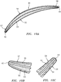
FIG. 10A is a cross-sectional perspective illustration of the vane with an alternative base section configuration. -
FIG. 10B is an enlarged view of a leading edge portion of the vane inFIG. 10A . -
FIG. 10C is an enlarged view of a trailing edge portion of the vane inFIG. 10A . -
FIG. 11 is a side cutaway illustration of a gas turbine engine configured with a plurality of the vanes (one visible inFIG. 11 ). -
FIGS. 1 and2 illustrate a multi-material vane 20 (e.g., a metal-composite vane) for a gas turbine engine. Thisvane 20 may be configured as a structural guide vane; e.g., a structural exit guide vane. For example, referring toFIG. 3 , thevane 20 may extend between and be structurally tied to aninner structure 22 of the gas turbine engine and anouter structure 24 of the gas turbine engine. With such a configuration, thevane 20 is configured to transfer loads between theinner structure 22 and theouter structure 24. Thevane 20 may also or alternatively be configured to direct flow within a flowpath 26 (e.g., a bypass flowpath) of the gas turbine engine. Thevane 20 of the present disclosure, however, is not limited to such an exemplary vane configuration or arrangement within the gas turbine engine. - Referring to
FIG. 1 , thevane 20 includes avane airfoil 28, a vane inner platform 29 (e.g., a shroud segment) and a vane outer platform 30 (e.g., a shroud segment). Thevane 20 ofFIG. 1 also include a vaneinner mount 31 and a vaneouter mount 32. Of course, it is contemplated thevane 20 may alternatively be configured without one or more of the vane components 29-32 and/or include one or more additional vane components. For example, in some embodiments, theinner platform 29 and/or theouter platform 30 may be configured discrete from thevane 20. - The
vane airfoil 28 ofFIG. 1 extends spanwise along aspan line 34 between an airfoilinner end 36 and an airfoilouter end 38, where the airfoilouter end 38 is positioned radially outboard of the airfoilinner end 36. Thevane airfoil 28 extends longitudinally along acamber line 40 between an (e.g., forward, upstream)airfoil leading edge 42 and an (e.g., aft, downstream)airfoil trailing edge 44. Referring toFIG. 2 , thevane airfoil 28 extends laterally (e.g., widthwise) between an (e.g., pressure, concave) airfoilfirst side 46 and an (e.g., suction, convex) airfoilsecond side 48. Referring toFIGS. 1 and2 , each of thesevane airfoil elements inner end 36 and the airfoilouter end 38. - Referring to
FIG. 1 , thevane airfoil 28 has an airfoilinner end portion 50, an airfoilouter end portion 51 and an airfoilintermediate portion 52. Each of these airfoil portions 50-52 defines a respective part of theairfoil elements FIG. 2 . Theintermediate portion 52 extends spanwise between and to theinner end portion 50 and theouter end portion 51. Theinner end portion 50 is arranged at the airfoilinner end 36, and is connected to the vaneinner platform 29. Theouter end portion 51 is arranged at the airfoilouter end 38, and is connected to the vaneouter platform 30. - Referring to
FIG. 3 , the vaneinner platform 29 is configured to form an inner peripheral portion of theflowpath 26. The vaneouter platform 30 is positioned radially outboard of the vaneinner platform 29. The vaneouter platform 30 is configured to form an outer peripheral portion of theflowpath 26. - The vane
inner mount 31 is configured to attach and structurally tie thevane 20 to theinner structure 22. The vaneouter mount 32 is configured to attach and structurally tie thevane 20 to theouter structure 24. Referring toFIG. 1 , the vaneinner mount 31 is positioned radially inboard of and connected to the vaneinner platform 29. The vaneouter mount 32 is position radially outboard of and connected to the vaneouter platform 30. - The
vane airfoil 28 ofFIGS. 1 and2 is configured as a multi-material (e.g., bi-material) airfoil; e.g., a metallic-composite hybrid airfoil. Thevane airfoil 28 ofFIGS. 1 and2 , for example, includes anairfoil base section 54, one or moreairfoil side sections base section 54 may be constructed from or otherwise base section material. An example of the base section material is metal such as, but not limited to, steel, titanium (Ti), aluminum (Al), nickel (Ni) or alloys thereof. Thefirst side section 55 may be constructed from or otherwise include first side section non-metal material. Thesecond side section 56 may be constructed from or otherwise include second side section non-metal material, which second side section non-metal material may be the same or different than the first side section non-metal material. Examples of the first and the second side section non-metal materials include, but are not limited to, composite materials (e.g., materials including fiber-reinforcement within a polymer matrix, such as carbon fiber and/or fiberglass within a thermoset or thermoplastic matrix). Theleading edge sheath 57 may be constructed from or otherwise include leading edge sheath material. The trailingedge sheath 58 may be constructed from or otherwise include trailing edge sheath material, which trailing edge sheath material may be the same or different than the leading edge non-metal material. An example of the leading and the trailing edge sheath material is metal such as, but not limited to, steel, titanium (Ti), aluminum (Al), nickel (Ni) or alloys thereof, which metal may be the same or different than the metal of thebase section 54. - Referring to
FIG. 4 , thebase section 54 of thevane airfoil 28 may be configured integrally with one or more or each of the other vane components 29-32. The vane components 28-32 ofFIG. 4 , for example, are configured together as a monolithic metal body. The vane components 28-32, for example, may be cast, machined, additively manufactured or otherwise formed as a single body of material. The present disclosure, however, is not limited to such an exemplary monolithic metal body embodiment. - Referring to
FIG. 5 , thebase section 54 may have an I-beam and/or flared end configuration; e.g., an I-beam and/or flared end cross-sectional geometry when viewed, for example, in a plane perpendicular to thecamber line 40. Thebase section 54 ofFIGS. 4 and5 , for example, includes aninner end segment 60, anouter end segment 61 and anintermediate segment 62 where the edge segments 60-61 represent flange portions of the I-beam and/or flared end configuration and theintermediate segment 62 represents a web portion of the I-beam and/or flared end configuration. - The
inner end segment 60 ofFIG. 4 extends spanwise along thespan line 34 from the airfoilinner end 36 to an inner end of theintermediate segment 62. Theinner end segment 60 extends longitudinally along thecamber line 40 from a leadingend 64 of thebase section 54 to a trailingend 66 of thebase section 54. Theinner end segment 60 ofFIG. 5 extends laterally between an outerfirst side 68 of the base section 54 (here, the airfoil first side 46) and an outersecond side 70 of the base section 54 (here, the airfoil second side 48). Theinner end segment 60 ofFIG. 4 provides a transition between thebase section 54 and, more generally, thevane airfoil 28 and the vaneinner platform 29. - The
outer end segment 61 extends spanwise along thespan line 34 from the airfoilouter end 38 to an outer end of theintermediate segment 62. Theouter end segment 61 extends longitudinally along thecamber line 40 from the basesection leading end 64 to the basesection trailing end 66. Theouter end segment 61 ofFIG. 5 extends laterally between the base section outer first side 68 (here, the airfoil first side 46) and the base section outer second side 70 (here, the airfoil second side 48). Theouter end segment 61 ofFIG. 4 provides a transition between thebase section 54 and, more generally, thevane airfoil 28 and the vaneouter platform 30. - The
intermediate segment 62 extends spanwise along thespan line 34 from theinner end segment 60 to theouter end segment 61. Theintermediate segment 62 ofFIGS. 4 and6 extends longitudinally along thecamber line 40 from the basesection leading end 64 to the basesection trailing end 66. Theintermediate segment 62 ofFIG. 5 extends laterally between an innerfirst side 72 of thebase section 54 and an innersecond side 74 of thebase section 54. The base section innerfirst side 72 is laterally recessed inward (i.e., in a lateral direction towards the base section inner second side 74) from the base section outerfirst side 68 as well as the airfoilfirst side 46. The base section innersecond side 74 is laterally recessed inward (i.e., in a lateral direction towards the base section inner first side 72) from the base section outersecond side 70 as well as the airfoilsecond side 48. - Referring to
FIG. 5 , at an interface between theinner end segment 60 and theintermediate segment 62, theinner end segment 60 has alateral width 76 that is greater than alateral width 78 of theintermediate segment 62. At an interface between theouter end segment 61 and theintermediate segment 62, theouter end segment 61 has alateral width 80 that is greater than thelateral width 78 of theintermediate segment 62. - With the foregoing configuration, the
base section 54 is configured with one ormore recesses first recess 82 is disposed at the airfoil first side 46 (seeFIG. 2 ) and projects partially into thebase section 54 to theintermediate segment 62. Thesecond recess 84 is disposed at the airfoil second side 48 (seeFIG. 2 ) and projects partially into thebase section 54 to theintermediate segment 62. Theintermediate segment 62, however, (e.g., completely) laterally separates thefirst recess 82 from thesecond recess 84. Theintermediate segment 62 ofFIG. 4 and, more particularly, theentire base section 54, for example, is configured as an aperture free body. Thefirst recess 82 and thesecond recess 84 may thereby be (e.g., completely) discrete from one another. - The
intermediate segment 62 ofFIG. 4 includes an intermediate segmentinner portion 86, an intermediate segmentouter portion 87 and an intermediate segmentintermediate portion 88. These intermediate segment portions 86-88 are longitudinally aligned along thecamber line 40. Theintermediate portion 88 extends spanwise between and to theinner portion 86 and theouter portion 87. Referring toFIG. 5 , theinner portion 86 provides a lateral width transition between theinner end segment 60 and theintermediate portion 88 of theintermediate segment 62. Similarly, theouter portion 87 provides a lateral width transition between theouter end segment 61 and theintermediate portion 88 of theintermediate segment 62. For example, referring toFIG. 7 , one or eachportion portion end segment intermediate portion 88. Referring toFIG. 8 , one or eachportion portion 86, 87 (e.g., smoothly, continuously and/or otherwise) tapers down from the lateral width of theend segment intermediate portion 88. The present disclosure, however, is not limited to including such transitions. - Referring to
FIGS. 1 and2 , thefirst side section 55 is arranged at the airfoilfirst side 46 and connected (e.g., bonded and/or otherwise attached) to thebase section 54. Thefirst side section 55 ofFIGS. 1 and2 , for example, is seated within thefirst recess 82 and is connected to theintermediate segment 62. - The
first side section 55 extends longitudinally along thecamber line 40 from a leadingend 90 of thefirst side section 55 to a trailingend 92 of thefirst side section 55. The first sidesection leading end 90 is aligned with and adjacent the basesection leading end 64. The first sidesection trailing end 92 is aligned with and adjacent the basesection trailing end 66. Thefirst side section 55 extends spanwise between and spanwise abuts theinner end segment 60 and theouter end segment 61. Thefirst side section 55 extends laterally out from thebase section 54 and itsintermediate segment 62 to the airfoilfirst side 46. - The
second side section 56 is arranged at the airfoilsecond side 48 and connected (e.g., bonded and/or otherwise attached) to thebase section 54. Thesecond side section 56 ofFIGS. 1 and2 , for example, is seated within thesecond recess 84 and is connected to theintermediate segment 62. - The
second side section 56 extends longitudinally along thecamber line 40 from a leadingend 94 of thesecond side section 56 to a trailingend 96 of thesecond side section 56. The second sidesection leading end 94 is aligned with and adjacent the basesection leading end 64. The second sidesection trailing end 96 is aligned with and adjacent the basesection trailing end 66. Thesecond side section 56 extends spanwise between and spanwise abuts theinner end segment 60 and theouter end segment 61. Thesecond side section 56 extends laterally out from thebase section 54 and itsintermediate segment 62 to the airfoilsecond side 48. - Referring to
FIG. 2 , since theintermediate segment 62 is aperture free (e.g., solid), thebase section 54 and its intermediate segment 62 (e.g., completely) separate thefirst side section 55 from thesecond side section 56. This separation may facilitate a relatively low complexity manufacturing process. For example, thefirst recess 82 may first be (e.g., completely) filled with the first non-metal material to form thefirst side section 55. The body may then be flipped over and thesecond recess 84 may then be (e.g., completely) filled with the second non-metal material to form thesecond side section 56, or vice versa. The present disclosure, however, is not limited to any particular manufacturing techniques or steps - Referring to
FIG. 9 , eachside section end length 98 along thespan line 34. Eachvane airfoil 28 has an end-to-end length 100 (e.g., vane height) along thespan line 34. Theside section length 98 may be less than theairfoil length 100 due to, for example, provision of theend portions - Referring again to
FIGS. 1 and2 , the leadingedge sheath 57 is arranged at (e.g., on, adjacent or proximate) theairfoil leading edge 42. Theleading edge sheath 57 is configured to at least partially (e.g., completely) form theairfoil leading edge 42. A first side 102 (e.g., wing) of theleading edge sheath 57 is configured to partially form the airfoilfirst side 46 and its exterior surface. Thisfirst side 102 overlaps and is connected (e.g., directly bonded and/or otherwise attached) to a leading end portion of thefirst side section 55. A second side 104 (e.g., wing) of theleading edge sheath 57 is configured to partially form the airfoilsecond side 48 and its exterior surface. Thissecond side 104 overlaps and is connected (e.g., directly bonded and/or otherwise attached) to a leading end portion of thesecond side section 56. Theleading edge sheath 57 also overlaps and is connected (e.g., directly bonded and/or otherwise attached) to thebase section 54 at the basesection leading end 64. With this configuration, the leadingedge sheath 57 provides protection for a leading edge portion of thevane airfoil 28. - Referring to
FIG. 1 , anaft end 106 of the leading edge sheathfirst side 102 is longitudinally abutted against and/or next to a first side forward portion (e.g., shelf) of theinner end segment 60. Similarly, anaft end 108 of the leading edge sheathsecond side 104 is longitudinally abutted against and/or next to a second side forward portion (e.g., shelf) of the inner end segment 60 (not visible inFIG. 1 ). - The
aft end 106 of the leading edge sheathfirst side 102 is longitudinally abutted against and/or next to a first side forward portion (e.g., shelf) of theouter end segment 61. Similarly, theaft end 108 of the leading edge sheathsecond side 104 is longitudinally abutted against and/or next to a second side forward portion (e.g., shelf) of the outer end segment 61 (not visible inFIG. 1 ). - Referring again to
FIGS. 1 and2 , the trailingedge sheath 58 is arranged at (e.g., on, adjacent or proximate) theairfoil trailing edge 44. The trailingedge sheath 58 is configured to at least partially (e.g., completely) form theairfoil trailing edge 44. A first side 110 (e.g., wing) of the trailingedge sheath 58 is configured to partially form the airfoilfirst side 46 and its exterior surface. Thisfirst side 110 overlaps and is connected (e.g., directly bonded and/or otherwise attached) to a trailing end portion of thefirst side section 55. A second side 112 (e.g., wing) of the trailingedge sheath 58 is configured to partially form the airfoilsecond side 48 and its exterior surface. Thissecond side 112 overlaps and is connected (e.g., directly bonded and/or otherwise attached) to a trailing end portion of thesecond side section 56. The trailingedge sheath 58 also overlaps and is connected (e.g., directly bonded and/or otherwise attached) to thebase section 54 at the basesection trailing end 66. With this configuration, the trailingedge sheath 58 provides protection for a trailing edge portion of thevane airfoil 28. - Referring to
FIG. 1 , aforward end 114 of the trailing edge sheathfirst side 110 is longitudinally abutted against and/or next to a first side forward portion (e.g., shelf) of theinner end segment 60. Similarly, aforward end 116 of the trailing edge sheathsecond side 112 is longitudinally abutted against and/or next to a second side forward portion (e.g., shelf) of the inner end segment 60 (not visible in but similar to / a mirror image of arrangement inFIG. 1 ). - The
forward end 114 of the trailing edge sheathfirst side 110 is longitudinally abutted against and/or next to a first side aft portion (e.g., shelf) of theouter end segment 61. Similarly, theforward end 116 of the trailing edge sheathsecond side 112 is longitudinally abutted against and/or next to a second side aft portion (e.g., shelf) of the outer end segment 61 (not visible in but similar to / a mirror image of arrangement inFIG. 1 ). - With the above described arrangement, the
first side section 55 is configured to form a portion of the airfoilfirst side 46 and the exterior flow surface of thevane airfoil 28 at thatfirst side 46 that extends longitudinally between theleading edge sheath 57 and the trailingedge sheath 58. Thefirst side section 55, the leadingedge sheath 57 and the trailingedge sheath 58 thereby collectively form theintermediate portion 52 of thevane airfoil 28 at itsfirst side 46. By contrast, thebase section 54 and itsinner end segment 60 along with theleading edge sheath 57 and the trailingedge sheath 58 collectively form theinner end portion 50 of thevane airfoil 28 at itsfirst side 46. Similarly, thebase section 54 and itsouter end segment 61 along with theleading edge sheath 57 and the trailingedge sheath 58 collectively form theouter end portion 51 of thevane airfoil 28 at itsfirst side 46. Thefirst side section 55 ofFIG. 1 does not, however, form theinner end portion 50 nor theouter end portion 51. - Similar to that described above with respect to the airfoil
first side 46, the second side section 56 (not visible in but similar to / a mirror image of arrangement inFIG. 1 ) is configured to form a portion of the airfoilsecond side 48 and the exterior flow surface of thevane airfoil 28 at thatsecond side 48 that extends longitudinally between theleading edge sheath 57 and the trailingedge sheath 58. Thesecond side section 56, the leadingedge sheath 57 and the trailingedge sheath 58 thereby collectively form theintermediate portion 52 of thevane airfoil 28 at itssecond side 48. By contrast, thebase section 54 and itsinner end segment 60 along with theleading edge sheath 57 and the trailingedge sheath 58 collectively form theinner end portion 50 of thevane airfoil 28 at itssecond side 48. Similarly, thebase section 54 and itsouter end segment 61 along with theleading edge sheath 57 and the trailingedge sheath 58 collectively form theouter end portion 51 of thevane airfoil 28 at itssecond side 48. Thesecond side section 56 does not, however, form theinner end portion 50 nor theouter end portion 51. - In some embodiments, referring to
FIG. 6 , at least a portion of theintermediate segment 62 of thebase section 54 may have a relatively constant lateral thickness asintermediate segment 62 extends between the basesegment leading end 64 and the basesegment trailing end 66. In other embodiments, referring toFIGS. 10A-C , at least a portion of theintermediate segment 62 of thebase section 54 may have a changing (e.g., tapering) lateral thickness asintermediate segment 62 extends to itsends -
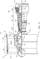
FIG. 11 is a side cutaway illustration of a gearedturbine engine 118 which may be configured with one or more (e.g., a circumferential array) of thevanes 20. Thisturbine engine 118 extends along anaxial centerline 120 between anupstream airflow inlet 122 and adownstream airflow exhaust 124. Theturbine engine 118 includes afan section 126, acompressor section 127, acombustor section 128 and aturbine section 129. Thecompressor section 127 includes a low pressure compressor (LPC)section 127A and a high pressure compressor (HPC)section 127B. Theturbine section 129 includes a high pressure turbine (HPT)section 129A and a low pressure turbine (LPT)section 129B. - The engine sections 126-129B are arranged sequentially along the
centerline 120 within anengine housing 130. Thishousing 130 includes an inner case 132 (e.g., a core case) and an outer case 134 (e.g., a fan case). Theinner case 132 may house one or more of theengine sections 127A-129B; e.g., an engine core. Theinner case 132 is configured with, includes or is part of theinner structure 22. Theouter case 134 may house at least thefan section 126. Theouter case 134 is configured with, includes or is part of theouter structure 24. - Each of the
engine sections - The
fan rotor 136 is connected to agear train 142, for example, through afan shaft 144. Thegear train 142 and theLPC rotor 137 are connected to and driven by theLPT rotor 140 through alow speed shaft 145. TheHPC rotor 138 is connected to and driven by theHPT rotor 139 through ahigh speed shaft 146. The shafts 144-146 are rotatably supported by a plurality ofbearings 148; e.g., rolling element and/or thrust bearings. Each of thesebearings 148 is connected to theengine housing 130 by at least one stationary structure such as, for example, an annular support strut. - During operation, air enters the
turbine engine 118 through theairflow inlet 122. This air is directed through thefan section 126 and into acore flowpath 150 and a bypass flowpath 152 (e.g., theflowpath 26 ofFIG. 3 ). Thecore flowpath 150 extends sequentially through theengine sections 127A-129B. The air within thecore flowpath 150 may be referred to as "core air". The bypass flowpath 152 extends through a bypass duct, which bypasses the engine core. The air within the bypass flowpath 152 may be referred to as "bypass air". - The core air is compressed by the
compressor rotors combustion chamber 154 of a combustor in thecombustor section 128. Fuel is injected into thecombustion chamber 154 and mixed with the compressed core air to provide a fuel-air mixture. This fuel air mixture is ignited and combustion products thereof flow through and sequentially cause theturbine rotors turbine rotors compressor rotors turbine rotor 140 also drives rotation of thefan rotor 136, which propels bypass air through and out of the bypass flowpath 152. The propulsion of the bypass air may account for a majority of thrust generated by theturbine engine 118, e.g., more than seventy-five percent (75%) of engine thrust. The turbine engine of the present disclosure, however, is not limited to the foregoing exemplary thrust ratio. - The
vane 20 / an assembly including thevane 20 may be included in various turbine engines other than the one described above. Thevane 20, for example, may be included in a geared turbine engine where a gear train connects one or more shafts to one or more rotors in a fan section, a compressor section and/or any other engine section. Alternatively, thevane 20 may be included in a turbine engine configured without a gear train. Thevane 20 may be included in a geared or non-geared turbine engine configured with a single spool, with two spools (e.g., seeFIG. 11 ), or with more than two spools. The turbine engine may be configured as a turbofan engine, a turbojet engine, a propfan engine, a pusher fan engine or any other type of turbine engine. The present disclosure therefore is not limited to any particular types or configurations of turbine engines. - While various embodiments of the present disclosure have been described, it will be apparent to those of ordinary skill in the art that many more embodiments and implementations are possible within the scope of the disclosure. For example, the present disclosure as described herein includes several aspects and embodiments that include particular features. Although these features may be described individually, it is within the scope of the present disclosure that some or all of these features may be combined with any one of the aspects and remain within the scope of the disclosure. Accordingly, the present disclosure is not to be restricted except in light of the attached claims and their equivalents.
Claims (15)
- A vane (20) for a gas turbine engine, comprising:an airfoil (28) extending along a camber line (40) between a leading edge (42) and a trailing edge (44), the airfoil (28) extending along a span line (34) between an inner end (36) and an outer end (38), the airfoil extending laterally between a first side (46) and a second side (48), and the airfoil (28) including a base section (54), a first side section (55), a second side section (56) and a sheath (57, 58);the base section (54) extending along the span line (34) between the inner end (36) and the outer end (38), the base section (54) laterally between the first side section (55) and the second side section (56), and the base section (54) comprising metal material;the first side section (55) connected to the base section (54) and partially forming the first side (46) of the airfoil (28), the first side section (55) comprising first non-metal material, optionally fiber-reinforced composite material;the second side section (56) connected to the base section (54) and partially forming the second side (48) of the airfoil (28), the second side section (56) comprising second non-metal material, optionally fiber-reinforced composite material; andthe sheath (57, 58) at least partially forming an edge of the airfoil (28), wherein the edge is the leading edge (42) or the trailing edge of the airfoil (44).
- The vane of claim 1, wherein the sheath completely forms the edge of the airfoil.
- The vane of claim 1 or 2, wherein the edge of the airfoil is the trailing edge (44) of the airfoil (28).
- The vane (20) of claim 1 or 2, wherein:the edge of the airfoil (28) is the leading edge (42) of the airfoil (28); and, optionally,the airfoil (28) further includes a second sheath (58) at least partially forming the trailing edge (44) of the airfoil (28).
- The vane (20) of any preceding claim, wherein the sheath (57, 58), is bonded to the base section (54), the first side section (55) and the second side section (56).
- The vane (20) of any preceding claim, wherein
the airfoil (28) has a span length extending along the span line (34) between the inner end (36) and the outer end (38) of the airfoil (28); and
an end-to-end length of the first side section (55) along the span line (34) is less than the span length. - The vane (20) of any preceding claim, wherein
the airfoil (28) has an inner end portion (50) at the inner end (36), an outer end portion (51) at the outer end (38) and an intermediate portion (52) extending along the span line (34) between the inner end portion (50) and the outer end portion (51);
at least the base section (54), the first side section (55), the second side section (56) and the sheath (57, 58), collectively form the intermediate portion (52); and
at least the base section (54) and the sheath (57, 58), collectively form at least one of the inner end portion (50) or the outer end portion (51),
wherein, optionally, neither the first side section (55) nor the second side section (56) forms at least one of the inner end portion (50) or the outer end portion (51). - The vane (20) of any preceding claim, wherein at least one of
the first side section (55) abuts against the base section (54) in a spanwise direction; or
the second side section (56) abuts against the base section (54) in the spanwise direction. - The vane (20) of any preceding claim, wherein the base section (54) extends along the camber line (40) through a channel which is laterally between the first side section (55) and the second side section (56).
- The vane (20) of any preceding claim, wherein
the base section (54) has a first portion and a second portion aligned along the camber (40) line;
the first portion is between the second portion and one of the inner end (36) and the outer end (38) along the span line (34);
the first portion has a first lateral thickness;
the second portion has a second lateral thickness that is less than the first lateral thickness; and
at least one of the first side section (55) or the second side section (56) overlaps and is connected to the first portion and the second portion. - The vane (20) of any preceding claim, further comprising:an inner platform (29), wherein the base section (54) extends along the span line (34) to and is formed integrally with the inner platform (29); and/oran outer platform (30), wherein the base section (54) extends along the span line (34) to and is formed integrally with the outer platform (30).
- The vane (20) of any preceding claim, wherein the base section (54) is configured as an aperture free body at least between the first side section (55) and the second side section (56).
- The vane (20) of any preceding claim, wherein the vane is configured as a structural guide vane of the gas turbine engine.
- A vane (20) for a gas turbine engine, comprising:an airfoil (28) extending longitudinally between a first edge and a second edge, the airfoil (28) extending spanwise between an inner end (36) and an outer end (38), the airfoil (28) extending laterally between a first side (46) and a second side (48), and the airfoil (28) including a base section (54), a first side section (55), a second side section (56) and a sheath (57) and/or (58);the base section laterally between the first side section (55) and the second side section (56), and the base section (54) comprising metal material;the first side section (55) connected to the base section (54) and partially forming the first side (46) of the airfoil (28), and the first side section (55) comprising first non-metal material;the second side section (56) connected to the base section (54) and partially forming the second side (48) of the airfoil (28), and the second side section (56) comprising second non-metal material; andthe sheath (57, 58), partially forming an exterior surface of the airfoil (28) and attached to the base section (54).
- A vane (20) for a gas turbine engine, comprising:an inner platform (29);an outer platform (30); andan airfoil (28) extending longitudinally between a first edge and a second edge, the airfoil (28) extending spanwise between the inner platform (29) and the outer platform (30), the airfoil (28) extending laterally between a first side (46) and a second side (48), and the airfoil (28) including a base section (54), a first side section (55) and a sheath (57, 58);the base section (54) extending spanwise between and formed integrally with the inner platform (29) and the outer platform (30), and the base section (54) comprising metal material;the first side section (55) connected to the base section (54) and partially forming the first side (46) of the airfoil (28), and the first side section (55) comprising first non-metal material; andthe sheath (57, 58) at least partially forming the first edge of the airfoil (28), wherein, optionally:the airfoil (28) further includes a second side section (56);the base (54) is laterally between and provides a divider between the first side section (55) and the second side section (56); andthe second side section (56) is connected to the base section (54) and partially forms the second side (48) of the airfoil (28), and the second side section (56) comprises second non-metal material.
Priority Applications (1)
| Application Number | Priority Date | Filing Date | Title |
|---|---|---|---|
| EP24161583.0A EP4353953A2 (en) | 2020-04-17 | 2021-04-16 | Multi-material vane for a gas turbine engine |
Applications Claiming Priority (1)
| Application Number | Priority Date | Filing Date | Title |
|---|---|---|---|
| US16/851,870 US11572796B2 (en) | 2020-04-17 | 2020-04-17 | Multi-material vane for a gas turbine engine |
Related Child Applications (1)
| Application Number | Title | Priority Date | Filing Date |
|---|---|---|---|
| EP24161583.0A Division EP4353953A2 (en) | 2020-04-17 | 2021-04-16 | Multi-material vane for a gas turbine engine |
Publications (1)
| Publication Number | Publication Date |
|---|---|
| EP3896255A1 true EP3896255A1 (en) | 2021-10-20 |
Family
ID=75581389
Family Applications (2)
| Application Number | Title | Priority Date | Filing Date |
|---|---|---|---|
| EP21169000.3A Pending EP3896255A1 (en) | 2020-04-17 | 2021-04-16 | Multi-material vane for a gas turbine engine |
| EP24161583.0A Pending EP4353953A2 (en) | 2020-04-17 | 2021-04-16 | Multi-material vane for a gas turbine engine |
Family Applications After (1)
| Application Number | Title | Priority Date | Filing Date |
|---|---|---|---|
| EP24161583.0A Pending EP4353953A2 (en) | 2020-04-17 | 2021-04-16 | Multi-material vane for a gas turbine engine |
Country Status (2)
| Country | Link |
|---|---|
| US (1) | US11572796B2 (en) |
| EP (2) | EP3896255A1 (en) |
Families Citing this family (1)
| Publication number | Priority date | Publication date | Assignee | Title |
|---|---|---|---|---|
| US11912389B1 (en) | 2022-01-31 | 2024-02-27 | Brunswick Corporation | Marine propeller |
Citations (5)
| Publication number | Priority date | Publication date | Assignee | Title |
|---|---|---|---|---|
| EP0764764A1 (en) * | 1995-09-25 | 1997-03-26 | General Electric Company | Partially-metallic blade for a gas turbine |
| EP1983160A2 (en) * | 2007-04-16 | 2008-10-22 | United Technologies Corporation | Gas turbine engine vane |
| EP2182168A1 (en) * | 2008-10-28 | 2010-05-05 | General Electric Company | Fabricated hybrid turbine blade |
| US20130319010A1 (en) * | 2012-06-05 | 2013-12-05 | Kwan Hui | Airfoil cover system |
| EP3064708A1 (en) * | 2015-03-05 | 2016-09-07 | Techspace Aero S.A. | Composite vane of an axial turbine-engine compressor with a reinforcing sheet and turbomachine with comprising such a vane |
Family Cites Families (74)
| Publication number | Priority date | Publication date | Assignee | Title |
|---|---|---|---|---|
| US3060561A (en) | 1959-07-27 | 1962-10-30 | Budd Co | Method of forming curved sandwich panels |
| US3002717A (en) | 1960-01-12 | 1961-10-03 | Pavlecka John | Airfoil structure |
| US3903578A (en) | 1972-02-28 | 1975-09-09 | United Aircraft Corp | Composite fan blade and method of construction |
| US4029838A (en) | 1975-09-24 | 1977-06-14 | The United States Of America As Represented By The Administrator Of The National Aeronautics And Space Administration | Hybrid composite laminate structures |
| US4118147A (en) | 1976-12-22 | 1978-10-03 | General Electric Company | Composite reinforcement of metallic airfoils |
| US4671470A (en) | 1985-07-15 | 1987-06-09 | Beech Aircraft Corporation | Method for fastening aircraft frame elements to sandwich skin panels covering same using woven fiber connectors |
| US4911990A (en) | 1988-02-05 | 1990-03-27 | United Technologies Corporation | Microstructurally toughened metallic article and method of making same |
| US5079099A (en) | 1988-02-05 | 1992-01-07 | United Technologies Corporation | Microstructurally toughened metal matrix composite article and method of making same |
| US4808485A (en) | 1988-02-05 | 1989-02-28 | United Technologies Corporation | Microstructurally toughened metal matrix composite article and method of making same |
| US4999256A (en) | 1988-02-05 | 1991-03-12 | United Technologies Corporation | Microstructurally toughened metal matrix composite article |
| US4885212A (en) | 1988-02-05 | 1989-12-05 | United Technologies Corporation | Microstructurally toughened metal matrix composite article and method of making same |
| US5015116A (en) | 1988-08-22 | 1991-05-14 | United Technologies Corporation | Structural joints of high dimensional stability |
| FR2688264A1 (en) | 1992-03-04 | 1993-09-10 | Snecma | BLADE TURBOMACHINE RECTIFIER HAVING A HONEYCOMB FACE LOADED WITH COMPOSITE MATERIAL. |
| FR2695163B1 (en) | 1992-09-02 | 1994-10-28 | Snecma | Hollow blade for a turbomachine and its manufacturing process. |
| US5370831A (en) | 1992-12-18 | 1994-12-06 | United Technologies Corporation | Method of molding polymeric skins for trim products |
| US5366765A (en) | 1993-05-17 | 1994-11-22 | United Technologies Corporation | Aqueous slurry coating system for aluminide coatings |
| US5687900A (en) | 1995-03-28 | 1997-11-18 | Mcdonnell Douglas Corporation | Structural panel having a predetermined shape and an associated method for superplastically forming and diffusion bonding the structural panel |
| US5692881A (en) | 1995-06-08 | 1997-12-02 | United Technologies Corporation | Hollow metallic structure and method of manufacture |
| JPH1054204A (en) | 1996-05-20 | 1998-02-24 | General Electric Co <Ge> | Multi-component blade for gas turbine |
| US5931641A (en) | 1997-04-25 | 1999-08-03 | General Electric Company | Steam turbine blade having areas of different densities |
| US5947688A (en) | 1997-12-22 | 1999-09-07 | General Electric Company | Frequency tuned hybrid blade |
| US5913661A (en) | 1997-12-22 | 1999-06-22 | General Electric Company | Striated hybrid blade |
| US6039542A (en) | 1997-12-24 | 2000-03-21 | General Electric Company | Panel damped hybrid blade |
| US6033186A (en) | 1999-04-16 | 2000-03-07 | General Electric Company | Frequency tuned hybrid blade |
| US6287080B1 (en) | 1999-11-15 | 2001-09-11 | General Electric Company | Elastomeric formulation used in the construction of lightweight aircraft engine fan blades |
| US6364616B1 (en) | 2000-05-05 | 2002-04-02 | General Electric Company | Submerged rib hybrid blade |
| US6371725B1 (en) * | 2000-06-30 | 2002-04-16 | General Electric Company | Conforming platform guide vane |
| US6514046B1 (en) | 2000-09-29 | 2003-02-04 | Siemens Westinghouse Power Corporation | Ceramic composite vane with metallic substructure |
| US6743504B1 (en) | 2001-03-01 | 2004-06-01 | Rohr, Inc. | Co-cured composite structures and method of making them |
| EP1247602B1 (en) | 2001-04-04 | 2008-02-20 | Siemens Aktiengesellschaft | Method for producing an airfoil |
| EP1499525A1 (en) | 2002-04-29 | 2005-01-26 | Rolls-Royce Naval Marine, Inc. | Propeller |
| JP4248974B2 (en) | 2003-09-02 | 2009-04-02 | 日東電工株式会社 | Light source device and liquid crystal display device |
| US7080805B2 (en) | 2004-05-05 | 2006-07-25 | The Boeing Company | Stiffened structures and associated methods |
| US7104760B2 (en) | 2004-05-05 | 2006-09-12 | General Electric Company | Hybrid bucket and related method of pocket design |
| US7410342B2 (en) | 2005-05-05 | 2008-08-12 | Florida Turbine Technologies, Inc. | Airfoil support |
| GB0516036D0 (en) | 2005-08-04 | 2005-09-14 | Rolls Royce Plc | Aerofoil |
| US7240718B2 (en) | 2005-09-13 | 2007-07-10 | United Technologies Corporation | Method for casting core removal |
| US7334997B2 (en) | 2005-09-16 | 2008-02-26 | General Electric Company | Hybrid blisk |
| US7508466B2 (en) | 2005-11-14 | 2009-03-24 | Cree, Inc. | Laser diode backlighting of LC display with at least one diode generating light beam having divergence angle and with display panel having beam spreader to increase divergence |
| CN102011986A (en) | 2005-11-15 | 2011-04-13 | 松下电器产业株式会社 | Surface illuminator and liquid crystal display using same |
| US7766625B2 (en) | 2006-03-31 | 2010-08-03 | General Electric Company | Methods and apparatus for reducing stress in turbine buckets |
| US7942639B2 (en) | 2006-03-31 | 2011-05-17 | General Electric Company | Hybrid bucket dovetail pocket design for mechanical retainment |
| US7429165B2 (en) | 2006-06-14 | 2008-09-30 | General Electric Company | Hybrid blade for a steam turbine |
| US7845841B2 (en) | 2006-08-28 | 2010-12-07 | Qualcomm Mems Technologies, Inc. | Angle sweeping holographic illuminator |
| US20080159856A1 (en) | 2006-12-29 | 2008-07-03 | Thomas Ory Moniz | Guide vane and method of fabricating the same |
| US7828526B2 (en) * | 2007-04-11 | 2010-11-09 | General Electric Company | Metallic blade having a composite inlay |
| US8107035B2 (en) | 2007-04-19 | 2012-01-31 | Necsel Intellectual Property | Laser backlighting for displays |
| WO2009116224A1 (en) | 2008-03-19 | 2009-09-24 | パナソニック株式会社 | Surface light source device |
| TWI325971B (en) | 2008-05-30 | 2010-06-11 | Au Optronics Corp | Light diffusion device, backlight module and liquid crystal display |
| US8333552B2 (en) | 2008-06-20 | 2012-12-18 | General Electric Company | Combined acoustic absorber and heat exchanging outlet guide vanes |
| CN102112799B (en) | 2008-08-05 | 2013-06-05 | 夏普株式会社 | Surface light source device |
| CN102197256A (en) | 2008-10-23 | 2011-09-21 | 夏普株式会社 | Illuminating device, planar light source device, display device and television receiver |
| BRPI0920050A2 (en) | 2008-11-04 | 2015-12-15 | Sharp Kk | surface lighting source apparatus and liquid crystal display apparatus |
| JP5029572B2 (en) | 2008-11-07 | 2012-09-19 | 住友電気工業株式会社 | Light guide plate, wiring module and electronic device |
| DE102008058786A1 (en) | 2008-11-24 | 2010-05-27 | Rolls-Royce Deutschland Ltd & Co Kg | Hybrid component for a gas turbine engine |
| US8177513B2 (en) | 2009-02-18 | 2012-05-15 | General Electric Company | Method and apparatus for a structural outlet guide vane |
| US8585368B2 (en) | 2009-04-16 | 2013-11-19 | United Technologies Corporation | Hybrid structure airfoil |
| US8083489B2 (en) | 2009-04-16 | 2011-12-27 | United Technologies Corporation | Hybrid structure fan blade |
| US7955054B2 (en) | 2009-09-21 | 2011-06-07 | Pratt & Whitney Rocketdyne, Inc. | Internally damped blade |
| GB0916758D0 (en) | 2009-09-24 | 2009-11-04 | Rolls Royce Plc | A hybrid component |
| US8381052B2 (en) | 2009-11-10 | 2013-02-19 | International Business Machines Corporation | Circuit and method for efficient memory repair |
| TWM388013U (en) | 2010-02-09 | 2010-09-01 | Power Digital Communications Co Ltd | Multi-directional lighting for a backlight board |
| TWI426302B (en) | 2010-02-12 | 2014-02-11 | Au Optronics Corp | Display device and light enhancement film of the display device |
| US20110205756A1 (en) | 2010-02-19 | 2011-08-25 | Pixtronix, Inc. | Light guides and backlight systems incorporating prismatic structures and light redirectors |
| FR2964427B1 (en) | 2010-09-06 | 2014-05-09 | Messier Dowty Sa | CARTRIDGE OF TURBOJET AND TURBOJET RECEIVING SUCH CARTERS |
| FR2970668B1 (en) * | 2011-01-24 | 2013-01-18 | Snecma | PROCESS FOR MAKING A METAL REINFORCEMENT |
| US8585268B2 (en) | 2011-10-21 | 2013-11-19 | Ergophos, Llc | Light-guide panel for display with laser backlight |
| US20140010662A1 (en) | 2012-07-03 | 2014-01-09 | United Technologies Corporation | Composite airfoil with integral platform |
| GB2549113A (en) * | 2016-04-05 | 2017-10-11 | Rolls Royce Plc | Composite bodies and their manufacture |
| US10260523B2 (en) | 2016-04-06 | 2019-04-16 | Rolls-Royce North American Technologies Inc. | Fluid cooling system integrated with outlet guide vane |
| US10570917B2 (en) * | 2016-08-01 | 2020-02-25 | United Technologies Corporation | Fan blade with composite cover |
| FR3063514B1 (en) * | 2017-03-02 | 2019-04-12 | Safran | TURBOMACHINE BLADE AND METHOD FOR MANUFACTURING THE SAME |
| US10513947B2 (en) * | 2017-06-05 | 2019-12-24 | United Technologies Corporation | Adjustable flow split platform cooling for gas turbine engine |
| FR3084695A1 (en) | 2018-07-31 | 2020-02-07 | Safran Aircraft Engines | COMPOSITE BLADE WITH METAL FRAME AND MANUFACTURING METHOD THEREOF |
-
2020
- 2020-04-17 US US16/851,870 patent/US11572796B2/en active Active
-
2021
- 2021-04-16 EP EP21169000.3A patent/EP3896255A1/en active Pending
- 2021-04-16 EP EP24161583.0A patent/EP4353953A2/en active Pending
Patent Citations (5)
| Publication number | Priority date | Publication date | Assignee | Title |
|---|---|---|---|---|
| EP0764764A1 (en) * | 1995-09-25 | 1997-03-26 | General Electric Company | Partially-metallic blade for a gas turbine |
| EP1983160A2 (en) * | 2007-04-16 | 2008-10-22 | United Technologies Corporation | Gas turbine engine vane |
| EP2182168A1 (en) * | 2008-10-28 | 2010-05-05 | General Electric Company | Fabricated hybrid turbine blade |
| US20130319010A1 (en) * | 2012-06-05 | 2013-12-05 | Kwan Hui | Airfoil cover system |
| EP3064708A1 (en) * | 2015-03-05 | 2016-09-07 | Techspace Aero S.A. | Composite vane of an axial turbine-engine compressor with a reinforcing sheet and turbomachine with comprising such a vane |
Also Published As
| Publication number | Publication date |
|---|---|
| EP4353953A2 (en) | 2024-04-17 |
| US20210324751A1 (en) | 2021-10-21 |
| US11572796B2 (en) | 2023-02-07 |
Similar Documents
| Publication | Publication Date | Title |
|---|---|---|
| EP2366871B1 (en) | Method and apparatus for a structural outlet guide vane | |
| EP2820297B1 (en) | Lightweight fan driving turbine | |
| EP2867501B1 (en) | Turbine blade platform with u-channel cooling holes | |
| EP3896255A1 (en) | Multi-material vane for a gas turbine engine | |
| EP3617453B1 (en) | Fan blade having closed metal sheath | |
| US11286781B2 (en) | Multi-disk bladed rotor assembly for rotational equipment | |
| US11371351B2 (en) | Multi-disk bladed rotor assembly for rotational equipment | |
| US11795831B2 (en) | Multi-material vane for a gas turbine engine | |
| WO2017204941A1 (en) | System for a low swirl low pressure turbine | |
| US11339673B2 (en) | Rotor assembly with internal vanes | |
| US11401814B2 (en) | Rotor assembly with internal vanes | |
| US20210222567A1 (en) | Rotor blade and method for forming a rotor blade | |
| US11781432B2 (en) | Nested vane arrangement for gas turbine engine | |
| EP3108103B1 (en) | Fan blade for a gas turbine engine | |
| EP3663520B1 (en) | Composite fan blade with leading edge sheath | |
| EP3851637B1 (en) | Rotor assembly for a gas turbine engine | |
| EP3851639B1 (en) | Rotor blade and rotor assembly for a gas turbine engine | |
| US20230160315A1 (en) | Bore compartment seals for gas turbine engines |
Legal Events
| Date | Code | Title | Description |
|---|---|---|---|
| PUAI | Public reference made under article 153(3) epc to a published international application that has entered the european phase |
Free format text: ORIGINAL CODE: 0009012 |
|
| STAA | Information on the status of an ep patent application or granted ep patent |
Free format text: STATUS: THE APPLICATION HAS BEEN PUBLISHED |
|
| AK | Designated contracting states |
Kind code of ref document: A1 Designated state(s): AL AT BE BG CH CY CZ DE DK EE ES FI FR GB GR HR HU IE IS IT LI LT LU LV MC MK MT NL NO PL PT RO RS SE SI SK SM TR |
|
| B565 | Issuance of search results under rule 164(2) epc |
Effective date: 20210922 |
|
| STAA | Information on the status of an ep patent application or granted ep patent |
Free format text: STATUS: REQUEST FOR EXAMINATION WAS MADE |
|
| 17P | Request for examination filed |
Effective date: 20220420 |
|
| RBV | Designated contracting states (corrected) |
Designated state(s): AL AT BE BG CH CY CZ DE DK EE ES FI FR GB GR HR HU IE IS IT LI LT LU LV MC MK MT NL NO PL PT RO RS SE SI SK SM TR |
|
| RAP3 | Party data changed (applicant data changed or rights of an application transferred) |
Owner name: RTX CORPORATION |
|
| RIC1 | Information provided on ipc code assigned before grant |
Ipc: F01D 9/02 20060101ALI20231027BHEP Ipc: F01D 5/28 20060101ALI20231027BHEP Ipc: F01D 5/14 20060101AFI20231027BHEP |
|
| GRAP | Despatch of communication of intention to grant a patent |
Free format text: ORIGINAL CODE: EPIDOSNIGR1 |
|
| STAA | Information on the status of an ep patent application or granted ep patent |
Free format text: STATUS: GRANT OF PATENT IS INTENDED |
|
| INTG | Intention to grant announced |
Effective date: 20231212 |
|
| GRAS | Grant fee paid |
Free format text: ORIGINAL CODE: EPIDOSNIGR3 |
|
| GRAA | (expected) grant |
Free format text: ORIGINAL CODE: 0009210 |
|
| STAA | Information on the status of an ep patent application or granted ep patent |
Free format text: STATUS: THE PATENT HAS BEEN GRANTED |