EP3896212A1 - Rotary clothes dryer - Google Patents
Rotary clothes dryer Download PDFInfo
- Publication number
- EP3896212A1 EP3896212A1 EP21167988.1A EP21167988A EP3896212A1 EP 3896212 A1 EP3896212 A1 EP 3896212A1 EP 21167988 A EP21167988 A EP 21167988A EP 3896212 A1 EP3896212 A1 EP 3896212A1
- Authority
- EP
- European Patent Office
- Prior art keywords
- slide sleeve
- latching means
- lever
- clothes dryer
- assigned
- Prior art date
- Legal status (The legal status is an assumption and is not a legal conclusion. Google has not performed a legal analysis and makes no representation as to the accuracy of the status listed.)
- Granted
Links
Images


Classifications
-
- D—TEXTILES; PAPER
- D06—TREATMENT OF TEXTILES OR THE LIKE; LAUNDERING; FLEXIBLE MATERIALS NOT OTHERWISE PROVIDED FOR
- D06F—LAUNDERING, DRYING, IRONING, PRESSING OR FOLDING TEXTILE ARTICLES
- D06F57/00—Supporting means, other than simple clothes-lines, for linen or garments to be dried or aired
- D06F57/02—Supporting means, other than simple clothes-lines, for linen or garments to be dried or aired mounted on pillars, e.g. rotatably
- D06F57/04—Supporting means, other than simple clothes-lines, for linen or garments to be dried or aired mounted on pillars, e.g. rotatably and having radial arms, e.g. collapsible
Definitions
- the invention relates to a rotary clothes dryer with support arms which are hingedly arranged on a slide sleeve which can be relocated along a mast and can be transferred selectively into a resting position and into an expanded position, wherein the mast has a first latching means assigned to it, into which the slide sleeve latches in the expanded position, wherein the slide sleeve has a second latching means assigned to it for latching, wherein the second latching means has at least one pawl for expanding the support arms, wherein the pawl latches automatically into the first latching means in such a way that automatic movement of the slide sleeve from the expanded position into the resting position is prevented.
- Such a rotary clothes dryer is known, for example, from EP 2 354 297 B1 .
- the slide sleeve has a pull cable assigned to it, which is assigned to the slide sleeve via a pulley arrangement assigned to the mast and the slide sleeve.
- a tension is applied to the pull cable so that the slide sleeve is set in motion relative to the mast, and the support arms are transferred from the resting position to the expanded position.
- the pawl continuously latches into the first latching means during expansion, thereby preventing the slide sleeve from moving automatically from the expanded position to the resting position when no pulling force is applied to the pull cable.
- At least one line is arranged between the support arms in such a way that several line sections arranged parallel to each other are stretched over the length of the support arms in the expanded position of the support arms.
- rotary clothes dryers which do not have a pull cord for opening.
- the slide sleeve with the support arms on the mast must be pushed vertically upwards by hand, which involves an increasing amount of effort with increasing height and line tension and which is ergonomically unfavourable for this reason alone.
- the object of the invention is to provide a rotary clothes dryer whose support arms can be transferred from the resting position to the expanded position with little effort and which, in addition, enables the lines to be tensioned in a simple and easy manner.
- the slide sleeve has a ratchet lever assigned to it, which is arranged on the slide sleeve so as to be tiltable between a resting position and an operating position, wherein the ratchet lever has a grip section and a projection, wherein the projection latches into the first latching means when the ratchet lever moves to the operating position.
- the pawl prevents backward movement of the slide sleeve when it is transferred from the resting position to the expanded position.
- the pawl latches into the first latching means in such a way that the slide sleeve can be gradually transferred from the resting position to the expanded position, wherein the slide sleeve cannot move automatically from the expanded position to the resting position.
- the rotary clothes dryer is expanded by the ratchet lever latching into the first latching means during movement from the resting position to the operating position.
- the slide sleeve moves toward the expanded position when the ratchet lever is moved further toward the operating position.
- the ratchet lever forms a climbing means or climbing aid by which the slide sleeve moves from the resting position to the expanded position along the mast.
- the rotary clothes dryer By repeatedly moving the ratchet lever between the resting position and the operating position, the rotary clothes dryer is expanded and the support arms move in the direction of the expanded position. As it does so, the slide sleeve climbs upwards along the mast and the rotary clothes dryer expands gradually.
- the movement of the ratchet lever corresponds to the movement of a ratchet.
- the pawl may have a locking lever assigned to it. By means of the locking lever, the pawl can be actuated and, in doing so, spaced away from the first latching means. This makes it possible to transfer the slide sleeve from the expanded position to the resting position.
- the pawl may have a spring element assigned to it which automatically pushes the pawl into the first latching means. This can prevent the pawl from inadvertently disengaging from the first latching means and the slide sleeve from automatically moving from the expanded position to the resting position.
- the locking lever may have a pusher section, wherein, when the pusher section is actuated, the pawl is spaced away from the first latching means so that the slide sleeve moves from the expanded position to the resting position.
- the locking lever is preferably hinged to the slide sleeve.
- the pusher section is preferably formed from a free end of the locking lever, which is opposite the pawl. When a compressive force is applied to the pusher section, the pawl moves out of the first latching means and the slide sleeve can move from the expanded position to the resting position.
- the first latching means may be in the form of a toothed rack.
- the pawl of the slide sleeve can latch into the first latching means at such an early stage that further expanding of the support arms up to the maximum line tension can be achieved with particularly low effort.
- the ratchet lever can be attached to the slide sleeve via a swivelling lever.
- the ratchet lever preferably performs a circular movement around the hinged connection of the ratchet lever during movement between the resting position and the operating position.
- the ratchet lever may be attached to the slide sleeve via the swivelling lever.
- the swivelling lever in turn is hinged at one end to the slide sleeve.
- the ratchet lever is hinged to the other end of the swivelling lever.
- the swivelling lever can swivel out, thereby spacing the ratchet lever from the slide sleeve in such a way that the ratchet lever cannot jam in the first latching means.
- a second spring element can be assigned to the ratchet lever, which automatically moves the ratchet lever into the resting position. This ensures that the ratchet lever is spaced from the first latching means when the expansion of the rotary clothes dryer is complete.
- the second spring element is preferably arranged between the ratchet lever and the swivelling lever.
- a handle can be assigned to the slide sleeve. This makes the slide sleeve particularly ergonomic to operate.
- At least one line may be assigned to the support arms.
- the line is arranged between the support arms in such a way that several line sections which are arranged parallel to each other are stretched in the expanded position.
- the line, or the line arrangement is tensioned when the support arms are transferred from the resting position to the expanded position.
- the slide sleeve can be positioned in such a way that the line, or the line arrangement, has the desired tension.
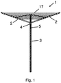
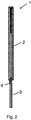
- Figures 1 and 2 show a rotary clothes dryer 1 with support arms 2, which are hingedly arranged on a slide sleeve 4, which is relocatable along a mast 3.
- a line 17 is assigned to the support arms 2, wherein the line 17 is assigned to the support arms 2 in such a way that a plurality of line sections, which are arranged parallel to one another, are obtained.
- the support arms 2 can optionally be moved into a resting position ( Fig. 2 ) and into an expanded position ( Fig. 1 ).
- Figures 3 to 6 show the slide sleeve 4 arranged on the mast 3 in detail.
- a first latching means 5 is assigned to the mast 3, into which the slide sleeve 4 latches in the expanded position.
- the first latching means 5 is designed as a toothed rack.
- the mast 3 has a groove which accommodates the first latching means 5 in the form of the toothed rack.
- a second latching means 6 is assigned to the slide sleeve 4 for latching into the first latching means 5, the second latching means 6 having a pawl 7 for expanding the support arms 2, wherein the pawl 7 automatically latches into the first latching means 5 in such a way that an automatic movement of the slide sleeve 4 from the expanded position into the resting position is prevented.
- a ratchet lever 8 is hingedly assigned to the slide sleeve 4, wherein the ratchet lever 8 is arranged on the slide sleeve 4 so as to be tiltable between a resting position and an operating position.
- the ratchet lever 8 has a grip section 9 and a projection 10, wherein the projection 10 latches into the first latching means 5 when the ratchet lever 8 moves to the operating position.
- the ratchet lever 8 is attached to the slide sleeve 4 via a swivelling lever 14, wherein a second spring element 15 is assigned to the ratchet lever 8, which automatically transfers the ratchet lever 8 into the resting position.
- the second spring element 15 is arranged between the ratchet lever 8 and the swivelling lever 14.
- the expanding of the rotary clothes dryer 1 is happens by the latching lever 8 latching into the first latching means 5 during the movement from the resting position to the operating position.
- the ratchet lever 8 latches into the first latching means 5
- the slide sleeve 4 moves towards the expanded position when the ratchet lever 8 is moved further towards the operating position.
- the ratchet lever 8 forms a climbing aid by which the slide sleeve 4 moves from the resting position to the expanded position along the mast 3.
- the rotary clothes dryer 1 is expanded and the support arms 2 move in the direction of the expanded position. In doing so, the slide sleeve 4 climbs upward along the mast 3 and the rotary clothes dryer 1 expands gradually.
- the movement of the ratchet lever 8 corresponds to the movement of a ratchet.
- a locking lever 11 is assigned to the pawl 7. Furthermore, a first spring element 12 is assigned to the pawl 7, which automatically presses the pawl 7 into the first latching means 5.
- the locking lever 11 has a pusher section 13, wherein, when the pusher section 13 is actuated, the pawl 7 is spaced apart from the first latching means 5 so that the slide sleeve 4 can move from the expanded position to the resting position.
- the locking lever 11 is hinged to the slide sleeve 4.
- the pusher section 13 is formed from a free end of the locking lever 11, which is opposite to the pawl 7. When a compressive force is applied to the pusher section 13, the pawl 7 is spaced apart from the first latching means 5 and the slide sleeve 4 is allowed to move from the expanded position to the resting position.
- the slide sleeve 4 is formed as a handle 16 on the outer circumferential side.
- the pawl 7 of the second latching means 6 latches into the first latching means 5 and the slide sleeve 4 is locked, in the present representation in the expanded position.
- the ratchet lever 8 is located on the slide sleeve 4 and is in the resting position.
- the ratchet lever 8 is extended from the slide sleeve 4 and is in the operating position. During the transfer of the ratchet lever 8 from the resting position to the operating position, the projection 10 of the ratchet lever 8 has latched into the first latching means 5 of the mast 3 and the slide sleeve 4 has moved along the mast 3 towards the expanded position as the ratchet lever 8 has been actuated further.
- the pusher section 13 of the locking lever 11 is actuated so that the pawl 7 is spaced from the first latching means 5, and the slide sleeve 4 can be transferred from the expanded position to the resting position.
- Figure 6 shows the previously described slide sleeve 4, wherein for better illustration the second latching means 6 and the ratchet lever 8 are not shown.
- Figure 7 shows in detail the second latching means 6 with locking lever 11 and ratchet lever 8 with projection 10.
Landscapes
- Engineering & Computer Science (AREA)
- Textile Engineering (AREA)
- Detail Structures Of Washing Machines And Dryers (AREA)
- Holders For Apparel And Elements Relating To Apparel (AREA)
Abstract
Description
- The invention relates to a rotary clothes dryer with support arms which are hingedly arranged on a slide sleeve which can be relocated along a mast and can be transferred selectively into a resting position and into an expanded position, wherein the mast has a first latching means assigned to it, into which the slide sleeve latches in the expanded position, wherein the slide sleeve has a second latching means assigned to it for latching, wherein the second latching means has at least one pawl for expanding the support arms, wherein the pawl latches automatically into the first latching means in such a way that automatic movement of the slide sleeve from the expanded position into the resting position is prevented.
- Such a rotary clothes dryer is known, for example, from
EP 2 354 297 B1 - At least one line is arranged between the support arms in such a way that several line sections arranged parallel to each other are stretched over the length of the support arms in the expanded position of the support arms.
- The problem with the prior art rotary clothes dryer is that the arrangement consisting of the mast, slide sleeve, pulley arrangement and pull cables is often very stiff, or becomes increasingly stiff over time due to wear and contamination of the components involved. This means that a high pulling force is required to transfer the support arms from the resting position to the expanded position. Another disadvantage is that to achieve the highest line tension, the highest pulling force must be applied at the furthest distance from the mast. This is unfavourable from a safety point of view and also from an ergonomic point of view.
- In addition to the aforementioned rotary clothes dryer, rotary clothes dryers are also known which do not have a pull cord for opening. With these, however, the slide sleeve with the support arms on the mast must be pushed vertically upwards by hand, which involves an increasing amount of effort with increasing height and line tension and which is ergonomically unfavourable for this reason alone.
- The object of the invention is to provide a rotary clothes dryer whose support arms can be transferred from the resting position to the expanded position with little effort and which, in addition, enables the lines to be tensioned in a simple and easy manner.
- This object is achieved using the features of
claim 1. The dependent claims make reference to advantageous embodiments. - To achieve the objective, the slide sleeve has a ratchet lever assigned to it, which is arranged on the slide sleeve so as to be tiltable between a resting position and an operating position, wherein the ratchet lever has a grip section and a projection, wherein the projection latches into the first latching means when the ratchet lever moves to the operating position. The pawl prevents backward movement of the slide sleeve when it is transferred from the resting position to the expanded position. The pawl latches into the first latching means in such a way that the slide sleeve can be gradually transferred from the resting position to the expanded position, wherein the slide sleeve cannot move automatically from the expanded position to the resting position. The rotary clothes dryer is expanded by the ratchet lever latching into the first latching means during movement from the resting position to the operating position. Once the ratchet lever latches into the first latching means, the slide sleeve moves toward the expanded position when the ratchet lever is moved further toward the operating position. Thus, the ratchet lever forms a climbing means or climbing aid by which the slide sleeve moves from the resting position to the expanded position along the mast. When the ratchet lever is moved from the operating position to the resting position, the pawl latching into the first latching means prevents the slide sleeve from moving in the opposite direction. By repeatedly moving the ratchet lever between the resting position and the operating position, the rotary clothes dryer is expanded and the support arms move in the direction of the expanded position. As it does so, the slide sleeve climbs upwards along the mast and the rotary clothes dryer expands gradually. The movement of the ratchet lever corresponds to the movement of a ratchet.
- The pawl may have a locking lever assigned to it. By means of the locking lever, the pawl can be actuated and, in doing so, spaced away from the first latching means. This makes it possible to transfer the slide sleeve from the expanded position to the resting position.
- The pawl may have a spring element assigned to it which automatically pushes the pawl into the first latching means. This can prevent the pawl from inadvertently disengaging from the first latching means and the slide sleeve from automatically moving from the expanded position to the resting position.
- The locking lever may have a pusher section, wherein, when the pusher section is actuated, the pawl is spaced away from the first latching means so that the slide sleeve moves from the expanded position to the resting position. The locking lever is preferably hinged to the slide sleeve. The pusher section is preferably formed from a free end of the locking lever, which is opposite the pawl. When a compressive force is applied to the pusher section, the pawl moves out of the first latching means and the slide sleeve can move from the expanded position to the resting position.
- The first latching means may be in the form of a toothed rack. In this embodiment, it is possible to fix the slide sleeve in various positions along the mast. Furthermore, the pawl of the slide sleeve can latch into the first latching means at such an early stage that further expanding of the support arms up to the maximum line tension can be achieved with particularly low effort.
- The ratchet lever can be attached to the slide sleeve via a swivelling lever. The ratchet lever preferably performs a circular movement around the hinged connection of the ratchet lever during movement between the resting position and the operating position. To prevent the ratchet lever from jamming in the first latching means during the circular motion, the ratchet lever may be attached to the slide sleeve via the swivelling lever. The swivelling lever in turn is hinged at one end to the slide sleeve. The ratchet lever is hinged to the other end of the swivelling lever. When the ratchet lever is moved between the resting position and the operating position, the swivelling lever can swivel out, thereby spacing the ratchet lever from the slide sleeve in such a way that the ratchet lever cannot jam in the first latching means.
- A second spring element can be assigned to the ratchet lever, which automatically moves the ratchet lever into the resting position. This ensures that the ratchet lever is spaced from the first latching means when the expansion of the rotary clothes dryer is complete. In this case, the second spring element is preferably arranged between the ratchet lever and the swivelling lever.
- A handle can be assigned to the slide sleeve. This makes the slide sleeve particularly ergonomic to operate.
- At least one line may be assigned to the support arms. Preferably, the line is arranged between the support arms in such a way that several line sections which are arranged parallel to each other are stretched in the expanded position. The line, or the line arrangement, is tensioned when the support arms are transferred from the resting position to the expanded position. The slide sleeve can be positioned in such a way that the line, or the line arrangement, has the desired tension.
- Some embodiments of the rotary clothes dryer according to the invention are explained in more detail below with reference to the figures. These show, in each case schematically:
-
Fig. 1 a rotary clothes dryer in the expanded position; -
Fig. 2 a rotary clothes dryer in the resting position; -
Fig. 3 the slide sleeve in detail; -
Fig. 4 the slide sleeve in detail with folded-out latching means; -
Fig. 5 the slide sleeve in detail with the locking lever actuated; -
Fig. 6 the slide sleeve (without locking lever and ratchet lever); -
Fig. 7 front and rear sides of locking lever and ratchet lever. -
Figures 1 and2 show arotary clothes dryer 1 withsupport arms 2, which are hingedly arranged on aslide sleeve 4, which is relocatable along amast 3. Aline 17 is assigned to thesupport arms 2, wherein theline 17 is assigned to thesupport arms 2 in such a way that a plurality of line sections, which are arranged parallel to one another, are obtained. Thesupport arms 2 can optionally be moved into a resting position (Fig. 2 ) and into an expanded position (Fig. 1 ). -
Figures 3 to 6 show theslide sleeve 4 arranged on themast 3 in detail. A first latching means 5 is assigned to themast 3, into which theslide sleeve 4 latches in the expanded position. The first latching means 5 is designed as a toothed rack. For this purpose, themast 3 has a groove which accommodates the first latching means 5 in the form of the toothed rack. - A second latching means 6 is assigned to the
slide sleeve 4 for latching into the first latching means 5, the second latching means 6 having apawl 7 for expanding thesupport arms 2, wherein thepawl 7 automatically latches into the first latching means 5 in such a way that an automatic movement of theslide sleeve 4 from the expanded position into the resting position is prevented. - A
ratchet lever 8 is hingedly assigned to theslide sleeve 4, wherein theratchet lever 8 is arranged on theslide sleeve 4 so as to be tiltable between a resting position and an operating position. Theratchet lever 8 has agrip section 9 and aprojection 10, wherein theprojection 10 latches into the first latching means 5 when theratchet lever 8 moves to the operating position. - The
ratchet lever 8 is attached to theslide sleeve 4 via a swivellinglever 14, wherein asecond spring element 15 is assigned to theratchet lever 8, which automatically transfers theratchet lever 8 into the resting position. Thesecond spring element 15 is arranged between theratchet lever 8 and the swivellinglever 14. - The expanding of the
rotary clothes dryer 1 is happens by the latchinglever 8 latching into the first latching means 5 during the movement from the resting position to the operating position. Once theratchet lever 8 latches into the first latching means 5, theslide sleeve 4 moves towards the expanded position when theratchet lever 8 is moved further towards the operating position. Thus, theratchet lever 8 forms a climbing aid by which theslide sleeve 4 moves from the resting position to the expanded position along themast 3. - When the
ratchet lever 8 is moved from the operating position to the resting position, thepawl 7, which automatically latches into the first latching means 5, prevents theslide sleeve 4 from moving in the opposite direction. By repeatedly moving theratchet lever 8 between the resting position and the operating position, therotary clothes dryer 1 is expanded and thesupport arms 2 move in the direction of the expanded position. In doing so, theslide sleeve 4 climbs upward along themast 3 and therotary clothes dryer 1 expands gradually. The movement of theratchet lever 8 corresponds to the movement of a ratchet. - A locking
lever 11 is assigned to thepawl 7. Furthermore, afirst spring element 12 is assigned to thepawl 7, which automatically presses thepawl 7 into the first latching means 5. - The locking
lever 11 has apusher section 13, wherein, when thepusher section 13 is actuated, thepawl 7 is spaced apart from the first latching means 5 so that theslide sleeve 4 can move from the expanded position to the resting position. The lockinglever 11 is hinged to theslide sleeve 4. Thepusher section 13 is formed from a free end of the lockinglever 11, which is opposite to thepawl 7. When a compressive force is applied to thepusher section 13, thepawl 7 is spaced apart from the first latching means 5 and theslide sleeve 4 is allowed to move from the expanded position to the resting position. - In the present embodiment, the
slide sleeve 4 is formed as ahandle 16 on the outer circumferential side. - In the representation according to
figure 3 , thepawl 7 of the second latching means 6 latches into the first latching means 5 and theslide sleeve 4 is locked, in the present representation in the expanded position. Theratchet lever 8 is located on theslide sleeve 4 and is in the resting position. - In the representation according to
figure 4 , theratchet lever 8 is extended from theslide sleeve 4 and is in the operating position. During the transfer of theratchet lever 8 from the resting position to the operating position, theprojection 10 of theratchet lever 8 has latched into the first latching means 5 of themast 3 and theslide sleeve 4 has moved along themast 3 towards the expanded position as theratchet lever 8 has been actuated further. - In the representation according to
figure 5 , thepusher section 13 of the lockinglever 11 is actuated so that thepawl 7 is spaced from the first latching means 5, and theslide sleeve 4 can be transferred from the expanded position to the resting position. -
Figure 6 shows the previously describedslide sleeve 4, wherein for better illustration the second latching means 6 and theratchet lever 8 are not shown. -
Figure 7 shows in detail the second latching means 6 with lockinglever 11 and ratchetlever 8 withprojection 10.
Claims (10)
- Rotary clothes dryer (1) having support arms (2) which are hingedly arranged on a slide sleeve (4) which can be relocated along a mast (3) and can be moved selectively into a resting position and into an expanded position, wherein a first latching means (5) into which the slide sleeve (4) latches in the expanded position is assigned to the mast (3), wherein a second latching means (6) for latching is assigned to the slide sleeve (4), wherein the second latching means (6) has at least one pawl (7) for expanding the support arms (2), wherein the pawl (7) automatically latches into the first latching means (5) in such a manner that an automatic movement of the slide sleeve (4) from the expanded position into the resting position is prevented, characterized in that a ratchet lever (8) is assigned to the slide sleeve (4), which is arranged on the slide sleeve (4) so as to be tiltable between a resting position and an operating position, wherein the ratchet lever (8) has a grip section (9) and a projection (10), wherein the projection (10) latches into the first latching means (5) when the ratchet lever (8) moves into the operating position and the slide sleeve (4) moves towards the expanded position by the leverage of the ratchet lever (8).
- Rotary clothes dryer according to claim 1, characterized in that a locking lever (11) is assigned to the pawl (7).
- Rotary clothes dryer according to claim 1 or 2, characterized in that the pawl (7) is assigned a first spring element (12) which automatically presses the pawl (7) into the first latching means (5).
- Rotary clothes dryer according to claim 2 or 3, characterized in that the locking lever (11) has a pusher section (13), wherein the pawl (7) is spaced apart from the first latching means (5) when the pusher section (13) is actuated so that the slide sleeve (4) moves from the expanded position to the resting position.
- Rotary clothes dryer according to any one of claims 1 to 4, characterized in that the first latching means (5) is in the form of a toothed rack.
- Rotary clothes dryer according to any one of claims 1 to 5, characterized in that the ratchet lever (8) is attached to the slide sleeve (4) via a swivelling lever (14).
- Rotary clothes dryer according to any one of claims 1 to 6, characterized in that a second spring element (15) is assigned to the latching lever (8), which automatically transfers the latching lever (8) into the resting position.
- Rotary clothes dryer according to claim 7, characterized in that the second spring element is arranged between the ratchet lever (8) and the swivelling lever (14).
- Rotary clothes dryer according to any one of claims 1 to 8, characterized in that a handle (16) is formed from the slide sleeve (4).
- Rotary clothes dryer according to any one of claims 1 to 9, characterized in that at least one line (17) is assigned to the support arms (2).
Applications Claiming Priority (1)
| Application Number | Priority Date | Filing Date | Title |
|---|---|---|---|
| DE102020110211.9A DE102020110211B3 (en) | 2020-04-14 | 2020-04-14 | Rotary clothes dryer |
Publications (3)
| Publication Number | Publication Date |
|---|---|
| EP3896212A1 true EP3896212A1 (en) | 2021-10-20 |
| EP3896212B1 EP3896212B1 (en) | 2025-06-18 |
| EP3896212C0 EP3896212C0 (en) | 2025-06-18 |
Family
ID=75497822
Family Applications (1)
| Application Number | Title | Priority Date | Filing Date |
|---|---|---|---|
| EP21167988.1A Active EP3896212B1 (en) | 2020-04-14 | 2021-04-13 | Rotary clothes dryer |
Country Status (4)
| Country | Link |
|---|---|
| EP (1) | EP3896212B1 (en) |
| CN (1) | CN113529371B (en) |
| DE (1) | DE102020110211B3 (en) |
| PL (1) | PL3896212T3 (en) |
Families Citing this family (1)
| Publication number | Priority date | Publication date | Assignee | Title |
|---|---|---|---|---|
| EP4595804B1 (en) * | 2024-02-01 | 2025-10-29 | NerTes GmbH Mobile Ständertechnik | Expanding mechanism for a tensionable device and tensionable device |
Citations (6)
| Publication number | Priority date | Publication date | Assignee | Title |
|---|---|---|---|---|
| US116232A (en) * | 1871-06-20 | Improvement in lifting-jacks | ||
| US1616097A (en) * | 1925-09-18 | 1927-02-01 | Wallace Albert | Clothes-drying rack |
| US2896792A (en) * | 1955-04-01 | 1959-07-28 | William L Bodine | Apparatus for removably supporting and tensioning clotheslines |
| US20060180687A1 (en) * | 2003-08-29 | 2006-08-17 | Heinrich Wuster | Umbrella-type laundry drying apparatus |
| DE202004021340U1 (en) * | 2003-12-18 | 2007-08-23 | Brabantia Nederland B.V. | Rotary wash crab with linen tensioner |
| EP2354297B1 (en) | 2010-02-09 | 2012-05-09 | Leifheit Ag | Rotary clothes drier |
Family Cites Families (9)
| Publication number | Priority date | Publication date | Assignee | Title |
|---|---|---|---|---|
| US2661849A (en) | 1950-04-19 | 1953-12-08 | Robert Van Spalding | Combined clothesline reel and awning |
| GB1187603A (en) | 1967-07-11 | 1970-04-08 | Ass Sprayers Ltd | Improvements in Clothes Airers |
| GB1410305A (en) * | 1973-11-19 | 1975-10-15 | Andrew Tsang Ng Fai | Clothes hanger |
| DE4129699C2 (en) | 1991-09-06 | 1996-07-11 | Leifheit Ag | Collapsible clothes horse |
| DE10230571A1 (en) | 2002-07-05 | 2004-01-15 | Leifheit Ag | clothes dryer |
| DE102006057440A1 (en) | 2006-12-06 | 2008-06-19 | Leifheit Ag | Clothes dryer with tensioning device |
| CN104109968B (en) * | 2014-04-17 | 2016-08-10 | 浙江欧美嘉五金有限公司 | The stable automatic lifting airer of a kind of lifting |
| CN108756548B (en) * | 2018-06-27 | 2023-08-01 | 佛山市锐创汽车用品有限公司 | Locking device |
| CN209193469U (en) * | 2018-11-23 | 2019-08-02 | 中瑞机电工程(天津)有限公司 | Safe type movable hydraulic lift truck |
-
2020
- 2020-04-14 DE DE102020110211.9A patent/DE102020110211B3/en active Active
-
2021
- 2021-04-06 CN CN202110366976.0A patent/CN113529371B/en active Active
- 2021-04-13 PL PL21167988.1T patent/PL3896212T3/en unknown
- 2021-04-13 EP EP21167988.1A patent/EP3896212B1/en active Active
Patent Citations (6)
| Publication number | Priority date | Publication date | Assignee | Title |
|---|---|---|---|---|
| US116232A (en) * | 1871-06-20 | Improvement in lifting-jacks | ||
| US1616097A (en) * | 1925-09-18 | 1927-02-01 | Wallace Albert | Clothes-drying rack |
| US2896792A (en) * | 1955-04-01 | 1959-07-28 | William L Bodine | Apparatus for removably supporting and tensioning clotheslines |
| US20060180687A1 (en) * | 2003-08-29 | 2006-08-17 | Heinrich Wuster | Umbrella-type laundry drying apparatus |
| DE202004021340U1 (en) * | 2003-12-18 | 2007-08-23 | Brabantia Nederland B.V. | Rotary wash crab with linen tensioner |
| EP2354297B1 (en) | 2010-02-09 | 2012-05-09 | Leifheit Ag | Rotary clothes drier |
Also Published As
| Publication number | Publication date |
|---|---|
| CN113529371A (en) | 2021-10-22 |
| PL3896212T3 (en) | 2025-11-03 |
| DE102020110211B3 (en) | 2021-05-12 |
| EP3896212B1 (en) | 2025-06-18 |
| CN113529371B (en) | 2023-07-07 |
| EP3896212C0 (en) | 2025-06-18 |
Similar Documents
| Publication | Publication Date | Title |
|---|---|---|
| CN115817362B (en) | Clamp arm for bicycle carrier with ratchet mechanism | |
| CN106687656B (en) | Outside door handles for motor vehicles | |
| EP0404745A1 (en) | A telescopic cargo bar | |
| CN101680252B (en) | Device for locking an opening part of a jet engine nacelle with respect to a fixed part, and nacelle equipped with such a device | |
| CN1302224C (en) | Telescopic stand for optical or photographic apparatus and the like | |
| EP3896212B1 (en) | Rotary clothes dryer | |
| CN1431945A (en) | Tools for tensioning or loosening/opening spring clips | |
| CN1527920A (en) | Stabilizers with telescopic rods for tripods and similar devices | |
| US4682617A (en) | Shortenable umbrella having a telescopic stick | |
| US8215202B2 (en) | Cable length adjustment mechanism | |
| JP2019500257A (en) | Locking device for two parts related to each other | |
| US7127829B2 (en) | Umbrella-type laundry drying apparatus | |
| US4840338A (en) | Locking tripod leg | |
| CN109790954A (en) | The wealthy device of improved exhibition for image photographic tripod | |
| DK176378B1 (en) | Connecting part to an operating wire in an endoscopic treatment instrument | |
| KR890004827B1 (en) | Umbrella with a mechanism for locking and releasing a slider | |
| CN112513512B (en) | tripod leg hanger | |
| US10856685B2 (en) | Automatic adjustment tube for carpet stretcher tool | |
| US20030009853A1 (en) | Locking device with improved jumping means for retractable handle of luggage | |
| JPH0552500U (en) | Leg opening adjustment device on tripod | |
| DE102012103956B4 (en) | clothes dryer | |
| CN111385681A (en) | Loudspeaker box frame comprising another loudspeaker box connecting device and loudspeaker box comprising such a frame | |
| US2959993A (en) | Compressing tool with release means for the full stroke compelling mechanism | |
| EP1930494B1 (en) | Rotary clothes drier with trail device | |
| US1796572A (en) | Device for attaching fabric to airplane ribs |
Legal Events
| Date | Code | Title | Description |
|---|---|---|---|
| PUAI | Public reference made under article 153(3) epc to a published international application that has entered the european phase |
Free format text: ORIGINAL CODE: 0009012 |
|
| STAA | Information on the status of an ep patent application or granted ep patent |
Free format text: STATUS: THE APPLICATION HAS BEEN PUBLISHED |
|
| AK | Designated contracting states |
Kind code of ref document: A1 Designated state(s): AL AT BE BG CH CY CZ DE DK EE ES FI FR GB GR HR HU IE IS IT LI LT LU LV MC MK MT NL NO PL PT RO RS SE SI SK SM TR |
|
| B565 | Issuance of search results under rule 164(2) epc |
Effective date: 20210817 |
|
| STAA | Information on the status of an ep patent application or granted ep patent |
Free format text: STATUS: REQUEST FOR EXAMINATION WAS MADE |
|
| 17P | Request for examination filed |
Effective date: 20211125 |
|
| RBV | Designated contracting states (corrected) |
Designated state(s): AL AT BE BG CH CY CZ DE DK EE ES FI FR GB GR HR HU IE IS IT LI LT LU LV MC MK MT NL NO PL PT RO RS SE SI SK SM TR |
|
| STAA | Information on the status of an ep patent application or granted ep patent |
Free format text: STATUS: EXAMINATION IS IN PROGRESS |
|
| 17Q | First examination report despatched |
Effective date: 20230503 |
|
| GRAP | Despatch of communication of intention to grant a patent |
Free format text: ORIGINAL CODE: EPIDOSNIGR1 |
|
| STAA | Information on the status of an ep patent application or granted ep patent |
Free format text: STATUS: GRANT OF PATENT IS INTENDED |
|
| INTG | Intention to grant announced |
Effective date: 20250213 |
|
| GRAS | Grant fee paid |
Free format text: ORIGINAL CODE: EPIDOSNIGR3 |
|
| GRAA | (expected) grant |
Free format text: ORIGINAL CODE: 0009210 |
|
| STAA | Information on the status of an ep patent application or granted ep patent |
Free format text: STATUS: THE PATENT HAS BEEN GRANTED |
|
| AK | Designated contracting states |
Kind code of ref document: B1 Designated state(s): AL AT BE BG CH CY CZ DE DK EE ES FI FR GB GR HR HU IE IS IT LI LT LU LV MC MK MT NL NO PL PT RO RS SE SI SK SM TR |
|
| REG | Reference to a national code |
Ref country code: GB Ref legal event code: FG4D |
|
| REG | Reference to a national code |
Ref country code: CH Ref legal event code: EP |
|
| REG | Reference to a national code |
Ref country code: DE Ref legal event code: R096 Ref document number: 602021032329 Country of ref document: DE |
|
| REG | Reference to a national code |
Ref country code: CH Ref legal event code: EP |
|
| REG | Reference to a national code |
Ref country code: IE Ref legal event code: FG4D |
|
| U01 | Request for unitary effect filed |
Effective date: 20250626 |
|
| U07 | Unitary effect registered |
Designated state(s): AT BE BG DE DK EE FI FR IT LT LU LV MT NL PT RO SE SI Effective date: 20250702 |
|
| PG25 | Lapsed in a contracting state [announced via postgrant information from national office to epo] |
Ref country code: GR Free format text: LAPSE BECAUSE OF FAILURE TO SUBMIT A TRANSLATION OF THE DESCRIPTION OR TO PAY THE FEE WITHIN THE PRESCRIBED TIME-LIMIT Effective date: 20250919 Ref country code: NO Free format text: LAPSE BECAUSE OF FAILURE TO SUBMIT A TRANSLATION OF THE DESCRIPTION OR TO PAY THE FEE WITHIN THE PRESCRIBED TIME-LIMIT Effective date: 20250918 |
|
| PG25 | Lapsed in a contracting state [announced via postgrant information from national office to epo] |
Ref country code: HR Free format text: LAPSE BECAUSE OF FAILURE TO SUBMIT A TRANSLATION OF THE DESCRIPTION OR TO PAY THE FEE WITHIN THE PRESCRIBED TIME-LIMIT Effective date: 20250618 |
|
| PG25 | Lapsed in a contracting state [announced via postgrant information from national office to epo] |
Ref country code: RS Free format text: LAPSE BECAUSE OF FAILURE TO SUBMIT A TRANSLATION OF THE DESCRIPTION OR TO PAY THE FEE WITHIN THE PRESCRIBED TIME-LIMIT Effective date: 20250918 |
|
| PG25 | Lapsed in a contracting state [announced via postgrant information from national office to epo] |
Ref country code: IS Free format text: LAPSE BECAUSE OF FAILURE TO SUBMIT A TRANSLATION OF THE DESCRIPTION OR TO PAY THE FEE WITHIN THE PRESCRIBED TIME-LIMIT Effective date: 20251018 |
|
| PG25 | Lapsed in a contracting state [announced via postgrant information from national office to epo] |
Ref country code: SM Free format text: LAPSE BECAUSE OF FAILURE TO SUBMIT A TRANSLATION OF THE DESCRIPTION OR TO PAY THE FEE WITHIN THE PRESCRIBED TIME-LIMIT Effective date: 20250618 |
|
| PG25 | Lapsed in a contracting state [announced via postgrant information from national office to epo] |
Ref country code: CZ Free format text: LAPSE BECAUSE OF FAILURE TO SUBMIT A TRANSLATION OF THE DESCRIPTION OR TO PAY THE FEE WITHIN THE PRESCRIBED TIME-LIMIT Effective date: 20250618 |
|
| PG25 | Lapsed in a contracting state [announced via postgrant information from national office to epo] |
Ref country code: SK Free format text: LAPSE BECAUSE OF FAILURE TO SUBMIT A TRANSLATION OF THE DESCRIPTION OR TO PAY THE FEE WITHIN THE PRESCRIBED TIME-LIMIT Effective date: 20250618 |
|
| PG25 | Lapsed in a contracting state [announced via postgrant information from national office to epo] |
Ref country code: ES Free format text: LAPSE BECAUSE OF FAILURE TO SUBMIT A TRANSLATION OF THE DESCRIPTION OR TO PAY THE FEE WITHIN THE PRESCRIBED TIME-LIMIT Effective date: 20250618 |
|
| PLBI | Opposition filed |
Free format text: ORIGINAL CODE: 0009260 |
|
| REG | Reference to a national code |
Ref country code: CH Ref legal event code: L10 Free format text: ST27 STATUS EVENT CODE: U-0-0-L10-L00 (AS PROVIDED BY THE NATIONAL OFFICE) Effective date: 20260325 |
|
| PLAX | Notice of opposition and request to file observation + time limit sent |
Free format text: ORIGINAL CODE: EPIDOSNOBS2 |
|
| 26 | Opposition filed |
Opponent name: LEIFHEIT AG Effective date: 20260316 |
|
| PGFP | Annual fee paid to national office [announced via postgrant information from national office to epo] |
Ref country code: PL Payment date: 20260318 Year of fee payment: 6 |