EP3896099A1 - Cell culture tool and cell treatment method - Google Patents
Cell culture tool and cell treatment method Download PDFInfo
- Publication number
- EP3896099A1 EP3896099A1 EP19894692.3A EP19894692A EP3896099A1 EP 3896099 A1 EP3896099 A1 EP 3896099A1 EP 19894692 A EP19894692 A EP 19894692A EP 3896099 A1 EP3896099 A1 EP 3896099A1
- Authority
- EP
- European Patent Office
- Prior art keywords
- cells
- polymer
- layer
- culture instrument
- photothermal
- Prior art date
- Legal status (The legal status is an assumption and is not a legal conclusion. Google has not performed a legal analysis and makes no representation as to the accuracy of the status listed.)
- Pending
Links
- 0 CC(*(*)[N+](C)[O-])C1*C1 Chemical compound CC(*(*)[N+](C)[O-])C1*C1 0.000 description 1
Images





Classifications
-
- C—CHEMISTRY; METALLURGY
- C12—BIOCHEMISTRY; BEER; SPIRITS; WINE; VINEGAR; MICROBIOLOGY; ENZYMOLOGY; MUTATION OR GENETIC ENGINEERING
- C12M—APPARATUS FOR ENZYMOLOGY OR MICROBIOLOGY; APPARATUS FOR CULTURING MICROORGANISMS FOR PRODUCING BIOMASS, FOR GROWING CELLS OR FOR OBTAINING FERMENTATION OR METABOLIC PRODUCTS, i.e. BIOREACTORS OR FERMENTERS
- C12M47/00—Means for after-treatment of the produced biomass or of the fermentation or metabolic products, e.g. storage of biomass
- C12M47/02—Separating microorganisms from the culture medium; Concentration of biomass
-
- C—CHEMISTRY; METALLURGY
- C08—ORGANIC MACROMOLECULAR COMPOUNDS; THEIR PREPARATION OR CHEMICAL WORKING-UP; COMPOSITIONS BASED THEREON
- C08F—MACROMOLECULAR COMPOUNDS OBTAINED BY REACTIONS ONLY INVOLVING CARBON-TO-CARBON UNSATURATED BONDS
- C08F220/00—Copolymers of compounds having one or more unsaturated aliphatic radicals, each having only one carbon-to-carbon double bond, and only one being terminated by only one carboxyl radical or a salt, anhydride ester, amide, imide or nitrile thereof
- C08F220/02—Monocarboxylic acids having less than ten carbon atoms; Derivatives thereof
- C08F220/52—Amides or imides
- C08F220/54—Amides, e.g. N,N-dimethylacrylamide or N-isopropylacrylamide
-
- C—CHEMISTRY; METALLURGY
- C08—ORGANIC MACROMOLECULAR COMPOUNDS; THEIR PREPARATION OR CHEMICAL WORKING-UP; COMPOSITIONS BASED THEREON
- C08L—COMPOSITIONS OF MACROMOLECULAR COMPOUNDS
- C08L33/00—Compositions of homopolymers or copolymers of compounds having one or more unsaturated aliphatic radicals, each having only one carbon-to-carbon double bond, and only one being terminated by only one carboxyl radical, or of salts, anhydrides, esters, amides, imides or nitriles thereof; Compositions of derivatives of such polymers
- C08L33/18—Homopolymers or copolymers of nitriles
- C08L33/20—Homopolymers or copolymers of acrylonitrile
-
- C—CHEMISTRY; METALLURGY
- C09—DYES; PAINTS; POLISHES; NATURAL RESINS; ADHESIVES; COMPOSITIONS NOT OTHERWISE PROVIDED FOR; APPLICATIONS OF MATERIALS NOT OTHERWISE PROVIDED FOR
- C09D—COATING COMPOSITIONS, e.g. PAINTS, VARNISHES OR LACQUERS; FILLING PASTES; CHEMICAL PAINT OR INK REMOVERS; INKS; CORRECTING FLUIDS; WOODSTAINS; PASTES OR SOLIDS FOR COLOURING OR PRINTING; USE OF MATERIALS THEREFOR
- C09D133/00—Coating compositions based on homopolymers or copolymers of compounds having one or more unsaturated aliphatic radicals, each having only one carbon-to-carbon double bond, and at least one being terminated by only one carboxyl radical, or of salts, anhydrides, esters, amides, imides, or nitriles thereof; Coating compositions based on derivatives of such polymers
- C09D133/18—Homopolymers or copolymers of nitriles
- C09D133/20—Homopolymers or copolymers of acrylonitrile
-
- C—CHEMISTRY; METALLURGY
- C12—BIOCHEMISTRY; BEER; SPIRITS; WINE; VINEGAR; MICROBIOLOGY; ENZYMOLOGY; MUTATION OR GENETIC ENGINEERING
- C12M—APPARATUS FOR ENZYMOLOGY OR MICROBIOLOGY; APPARATUS FOR CULTURING MICROORGANISMS FOR PRODUCING BIOMASS, FOR GROWING CELLS OR FOR OBTAINING FERMENTATION OR METABOLIC PRODUCTS, i.e. BIOREACTORS OR FERMENTERS
- C12M23/00—Constructional details, e.g. recesses, hinges
- C12M23/20—Material Coatings
-
- C—CHEMISTRY; METALLURGY
- C12—BIOCHEMISTRY; BEER; SPIRITS; WINE; VINEGAR; MICROBIOLOGY; ENZYMOLOGY; MUTATION OR GENETIC ENGINEERING
- C12M—APPARATUS FOR ENZYMOLOGY OR MICROBIOLOGY; APPARATUS FOR CULTURING MICROORGANISMS FOR PRODUCING BIOMASS, FOR GROWING CELLS OR FOR OBTAINING FERMENTATION OR METABOLIC PRODUCTS, i.e. BIOREACTORS OR FERMENTERS
- C12M25/00—Means for supporting, enclosing or fixing the microorganisms, e.g. immunocoatings
-
- C—CHEMISTRY; METALLURGY
- C12—BIOCHEMISTRY; BEER; SPIRITS; WINE; VINEGAR; MICROBIOLOGY; ENZYMOLOGY; MUTATION OR GENETIC ENGINEERING
- C12M—APPARATUS FOR ENZYMOLOGY OR MICROBIOLOGY; APPARATUS FOR CULTURING MICROORGANISMS FOR PRODUCING BIOMASS, FOR GROWING CELLS OR FOR OBTAINING FERMENTATION OR METABOLIC PRODUCTS, i.e. BIOREACTORS OR FERMENTERS
- C12M33/00—Means for introduction, transport, positioning, extraction, harvesting, peeling or sampling of biological material in or from the apparatus
-
- C—CHEMISTRY; METALLURGY
- C12—BIOCHEMISTRY; BEER; SPIRITS; WINE; VINEGAR; MICROBIOLOGY; ENZYMOLOGY; MUTATION OR GENETIC ENGINEERING
- C12M—APPARATUS FOR ENZYMOLOGY OR MICROBIOLOGY; APPARATUS FOR CULTURING MICROORGANISMS FOR PRODUCING BIOMASS, FOR GROWING CELLS OR FOR OBTAINING FERMENTATION OR METABOLIC PRODUCTS, i.e. BIOREACTORS OR FERMENTERS
- C12M47/00—Means for after-treatment of the produced biomass or of the fermentation or metabolic products, e.g. storage of biomass
- C12M47/04—Cell isolation or sorting
-
- C—CHEMISTRY; METALLURGY
- C12—BIOCHEMISTRY; BEER; SPIRITS; WINE; VINEGAR; MICROBIOLOGY; ENZYMOLOGY; MUTATION OR GENETIC ENGINEERING
- C12N—MICROORGANISMS OR ENZYMES; COMPOSITIONS THEREOF; PROPAGATING, PRESERVING, OR MAINTAINING MICROORGANISMS; MUTATION OR GENETIC ENGINEERING; CULTURE MEDIA
- C12N5/00—Undifferentiated human, animal or plant cells, e.g. cell lines; Tissues; Cultivation or maintenance thereof; Culture media therefor
- C12N5/06—Animal cells or tissues; Human cells or tissues
- C12N5/0602—Vertebrate cells
-
- G—PHYSICS
- G03—PHOTOGRAPHY; CINEMATOGRAPHY; ANALOGOUS TECHNIQUES USING WAVES OTHER THAN OPTICAL WAVES; ELECTROGRAPHY; HOLOGRAPHY
- G03F—PHOTOMECHANICAL PRODUCTION OF TEXTURED OR PATTERNED SURFACES, e.g. FOR PRINTING, FOR PROCESSING OF SEMICONDUCTOR DEVICES; MATERIALS THEREFOR; ORIGINALS THEREFOR; APPARATUS SPECIALLY ADAPTED THEREFOR
- G03F7/00—Photomechanical, e.g. photolithographic, production of textured or patterned surfaces, e.g. printing surfaces; Materials therefor, e.g. comprising photoresists; Apparatus specially adapted therefor
- G03F7/004—Photosensitive materials
- G03F7/039—Macromolecular compounds which are photodegradable, e.g. positive electron resists
-
- G—PHYSICS
- G03—PHOTOGRAPHY; CINEMATOGRAPHY; ANALOGOUS TECHNIQUES USING WAVES OTHER THAN OPTICAL WAVES; ELECTROGRAPHY; HOLOGRAPHY
- G03F—PHOTOMECHANICAL PRODUCTION OF TEXTURED OR PATTERNED SURFACES, e.g. FOR PRINTING, FOR PROCESSING OF SEMICONDUCTOR DEVICES; MATERIALS THEREFOR; ORIGINALS THEREFOR; APPARATUS SPECIALLY ADAPTED THEREFOR
- G03F7/00—Photomechanical, e.g. photolithographic, production of textured or patterned surfaces, e.g. printing surfaces; Materials therefor, e.g. comprising photoresists; Apparatus specially adapted therefor
- G03F7/004—Photosensitive materials
- G03F7/09—Photosensitive materials characterised by structural details, e.g. supports, auxiliary layers
- G03F7/095—Photosensitive materials characterised by structural details, e.g. supports, auxiliary layers having more than one photosensitive layer
-
- G—PHYSICS
- G03—PHOTOGRAPHY; CINEMATOGRAPHY; ANALOGOUS TECHNIQUES USING WAVES OTHER THAN OPTICAL WAVES; ELECTROGRAPHY; HOLOGRAPHY
- G03F—PHOTOMECHANICAL PRODUCTION OF TEXTURED OR PATTERNED SURFACES, e.g. FOR PRINTING, FOR PROCESSING OF SEMICONDUCTOR DEVICES; MATERIALS THEREFOR; ORIGINALS THEREFOR; APPARATUS SPECIALLY ADAPTED THEREFOR
- G03F7/00—Photomechanical, e.g. photolithographic, production of textured or patterned surfaces, e.g. printing surfaces; Materials therefor, e.g. comprising photoresists; Apparatus specially adapted therefor
- G03F7/004—Photosensitive materials
- G03F7/09—Photosensitive materials characterised by structural details, e.g. supports, auxiliary layers
- G03F7/105—Photosensitive materials characterised by structural details, e.g. supports, auxiliary layers having substances, e.g. indicators, for forming visible images
-
- G—PHYSICS
- G03—PHOTOGRAPHY; CINEMATOGRAPHY; ANALOGOUS TECHNIQUES USING WAVES OTHER THAN OPTICAL WAVES; ELECTROGRAPHY; HOLOGRAPHY
- G03F—PHOTOMECHANICAL PRODUCTION OF TEXTURED OR PATTERNED SURFACES, e.g. FOR PRINTING, FOR PROCESSING OF SEMICONDUCTOR DEVICES; MATERIALS THEREFOR; ORIGINALS THEREFOR; APPARATUS SPECIALLY ADAPTED THEREFOR
- G03F7/00—Photomechanical, e.g. photolithographic, production of textured or patterned surfaces, e.g. printing surfaces; Materials therefor, e.g. comprising photoresists; Apparatus specially adapted therefor
- G03F7/20—Exposure; Apparatus therefor
- G03F7/2022—Multi-step exposure, e.g. hybrid; backside exposure; blanket exposure, e.g. for image reversal; edge exposure, e.g. for edge bead removal; corrective exposure
-
- C—CHEMISTRY; METALLURGY
- C08—ORGANIC MACROMOLECULAR COMPOUNDS; THEIR PREPARATION OR CHEMICAL WORKING-UP; COMPOSITIONS BASED THEREON
- C08F—MACROMOLECULAR COMPOUNDS OBTAINED BY REACTIONS ONLY INVOLVING CARBON-TO-CARBON UNSATURATED BONDS
- C08F2810/00—Chemical modification of a polymer
- C08F2810/50—Chemical modification of a polymer wherein the polymer is a copolymer and the modification is taking place only on one or more of the monomers present in minority
-
- C—CHEMISTRY; METALLURGY
- C12—BIOCHEMISTRY; BEER; SPIRITS; WINE; VINEGAR; MICROBIOLOGY; ENZYMOLOGY; MUTATION OR GENETIC ENGINEERING
- C12N—MICROORGANISMS OR ENZYMES; COMPOSITIONS THEREOF; PROPAGATING, PRESERVING, OR MAINTAINING MICROORGANISMS; MUTATION OR GENETIC ENGINEERING; CULTURE MEDIA
- C12N2509/00—Methods for the dissociation of cells, e.g. specific use of enzymes
-
- C—CHEMISTRY; METALLURGY
- C12—BIOCHEMISTRY; BEER; SPIRITS; WINE; VINEGAR; MICROBIOLOGY; ENZYMOLOGY; MUTATION OR GENETIC ENGINEERING
- C12N—MICROORGANISMS OR ENZYMES; COMPOSITIONS THEREOF; PROPAGATING, PRESERVING, OR MAINTAINING MICROORGANISMS; MUTATION OR GENETIC ENGINEERING; CULTURE MEDIA
- C12N2533/00—Supports or coatings for cell culture, characterised by material
- C12N2533/30—Synthetic polymers
Definitions
- cells at a desired position can be detached.
- a and B may be the same or different and are each independently a single bond or a functional group
- R 3 , R 4 , and R 9 may be the same or different and are each independently a hydrogen atom or an alkyl group
- R 6 and R 7 may be the same or different and are each independently a hydrogen atom, an alkyl group, or an aromatic ring
- the photosoluble and photothermal convertible polymer preferably includes a polymer represented by the following formula (6).
- monomers may be randomly polymerized or may be polymerized with regularity.
- FIGs. 3A to 3C are schematic views showing the configuration of a culture instrument 200 of the second embodiment.
- FIG. 3A is a schematic perspective view of the culture instrument 200
- FIG. 3B is a schematic cross-sectional view of the culture instrument 200 taken along line II-II of FIG. 3A
- FIG. 3C is a schematic cross-sectional view of a culture instrument 200 taken along line II-II of FIG. 3A in a state where cells are cultured in the culture instrument 200.
- the photoreactive layer 12 in the configuration of the culture instrument 100 of the first embodiment is composed of two layers.
- the culture instrument of the present invention was produced and whether cells at a desired position can be detached by the processing method of the present invention was examined.
Landscapes
- Health & Medical Sciences (AREA)
- Life Sciences & Earth Sciences (AREA)
- Engineering & Computer Science (AREA)
- Chemical & Material Sciences (AREA)
- Organic Chemistry (AREA)
- Wood Science & Technology (AREA)
- Zoology (AREA)
- Bioinformatics & Cheminformatics (AREA)
- Biotechnology (AREA)
- Biomedical Technology (AREA)
- Genetics & Genomics (AREA)
- Microbiology (AREA)
- Biochemistry (AREA)
- General Engineering & Computer Science (AREA)
- General Health & Medical Sciences (AREA)
- Sustainable Development (AREA)
- Physics & Mathematics (AREA)
- General Physics & Mathematics (AREA)
- Immunology (AREA)
- Molecular Biology (AREA)
- Cell Biology (AREA)
- Clinical Laboratory Science (AREA)
- Chemical Kinetics & Catalysis (AREA)
- Structural Engineering (AREA)
- Architecture (AREA)
- Medicinal Chemistry (AREA)
- Polymers & Plastics (AREA)
- Materials Engineering (AREA)
- Spectroscopy & Molecular Physics (AREA)
- Apparatus Associated With Microorganisms And Enzymes (AREA)
- Micro-Organisms Or Cultivation Processes Thereof (AREA)
- Addition Polymer Or Copolymer, Post-Treatments, Or Chemical Modifications (AREA)
Abstract
Description
- The present invention relates to a cell culture instrument and a cell processing method.
- In the case of recovering adherent cells cultured on a cell culture instrument such as a dish or the like, adhesion between the cells and the culture instrument is cut in the presence of a protease such as trypsin and a chelating agent such as EDTA, and released cells are detached and recovered (Patent Literature 1).
- Patent Literature 1:
WO2017/010100 - However, cells on the entire surface of the culture instrument can be recovered by the method using a protease, but the working position of the protease cannot be limited so that the cells at the desired position cannot be detached and recovered.
- Further, when the cells are cultured on a culture instrument, the cells adhere to one another to form a cell mass such as a sheet. In this case as well, cells on the entire surface of the culture instrument can be recovered by the method using a protease, but the working position of the protease cannot be limited so that the cells at the desired position cannot be recovered.
- With the foregoing in mind, it is an object of the present invention to provide a cell culture instrument capable of detaching cells at a desired position and a cell processing method using the cell culture instrument.
- In order to achieve the above object, the present invention provides a cell culture instrument (hereinafter, also referred to as a "culture instrument"), including: a substrate; and a photoreactive layer having a photosolubility and a photothermal convertibility, wherein the photoreactive layer is laminated on the substrate, and the photoreactive layer includes a polymer having a photosolubility and a photothermal convertibility.
- The present invention also provides a cell processing method (hereinafter, also referred to as a "processing method "), including: a culturing step of culturing cells in the cell culture instrument according to the present invention; a first irradiation step of irradiating the photoreactive layer with first light that causes photodissolution; and a second irradiation step of irradiating the photoreactive layer with second light that causes photothermal conversion.
- According to the present invention, cells at a desired position can be detached.
-
-
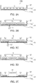
FIGs. 1A to 1C are schematic views showing an example of the configuration of a culture instrument of the first embodiment.FIG. 1A is a schematic perspective view of a culture instrument of the first embodiment,FIG. 1B is a schematic cross-sectional view of the culture instrument of the first embodiment taken along line I-I ofFIG. 1A, and FIG. 1C is a schematic cross-sectional view of aculture instrument 100 taken along line I-I ofFIG. 1A in a state where cells are cultured in theculture instrument 100. -
FIG. 2 is a schematic view showing an example of a cell processing method of the first embodiment. -
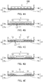
FIGs. 3A to 3C are schematic views showing an example of the configuration of a culture instrument of the second embodiment.FIG. 3A is a schematic perspective view of a culture instrument of the second embodiment,FIG. 3B is a schematic cross-sectional view of the culture instrument of the second embodiment taken along line II-II ofFIG. 3A, and FIG. 3C is a schematic cross-sectional view of aculture instrument 200 taken along line II-II ofFIG. 3A in a state where cells are cultured in theculture instrument 200. -
FIG. 4 is a schematic view showing an example of a cell processing method of the second embodiment. -
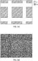
FIGs. 5A and 5B show a region of cells to be processed and the result after processing in Example 1.FIG. 5A shows a region of cells to be processed in a culture instrument, andFIG. 5B is a photograph showing the result of the culture instrument after processing by a processing method. -
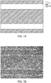
FIGs. 6A and 6B show a region of cells to be processed and the result after processing in Example 2.FIG. 6A shows a region of cells to be processed in a culture instrument, andFIG. 6B is a photograph showing the result of the culture instrument after processing by a processing method. -
FIGs. 7A and 7B show a region of cells to be processed and the result after processing in Example 3.FIG. 7A shows a region of cells to be processed in a culture instrument, andFIG. 7B is a photograph showing the result of the culture instrument after processing by a processing method. -
FIGs. 8A and 8B show a region of cells to be processed and the result after processing in Example 3.FIG. 8A shows a region of cells to be processed in a culture instrument, andFIG. 8B is a photograph showing the result of the culture instrument after processing by a processing method. -
FIGs. 9A and 9B show a region of cells to be processed and the result after processing in Example 4.FIG. 9A shows a region of cells to be processed in a culture instrument, andFIG. 9B is a photograph showing the result of the culture instrument after processing by a processing method. - In the present invention, "cells" mean, for example, isolated cells, cell masses composed of cells, tissues, or organs. The cells may be, for example, cultured cells or cells isolated from a living body. In addition, the cell mass, tissue, or organ may be, for example, a cell mass, a cell sheet, a tissue, or an organ made from the cells, or a cell mass, a tissue, or an organ isolated from a living body.
- In the present invention, "cell processing" may be used in any sense of, for example, detachment of cells, recovery of cells, removal of unnecessary cells, and retention or maintenance of necessary cells.
- Hereinafter, a cell culture instrument and a cell processing method of the present invention will be described in detail with reference to the drawings. The present invention, however, is not limited to the following description. In the following
FIGs. 1A to 9B , identical parts are indicated with identical reference signs, and the descriptions of the identical parts may be omitted. Furthermore, for convenience in explanation, the structure of each component shown inFIGs. 1A to 9B may be appropriately simplified, and the size, the ratio, and the like of components may be schematically shown and different from actual ones. Each embodiment can be described with reference to the descriptions of other embodiments, unless otherwise specified. - The present embodiment is an example of a cell culture instrument and a cell processing method.
FIGs. 1A to 1C are schematic views showing the configuration of aculture instrument 100 of the first embodiment.FIG. 1A is a schematic perspective view of theculture instrument 100,FIG. 1B is a schematic cross-sectional view of theculture instrument 100 taken along line I-I ofFIG. 1A, and FIG. 1C is a schematic cross-sectional view of theculture instrument 100 taken along line I-I ofFIG. 1A in a state where cells are cultured in theculture instrument 100. As shown inFIGs. 1A and 1B , theculture instrument 100 includes acontainer 11 and aphotoreactive layer 12. Thecontainer 11 has acircular substrate 11a and aside wall 11b surrounding the outer periphery of thesubstrate 11a. Thephotoreactive layer 12 includes a polymer having a photosolubility and a photothermal convertibility (hereinafter, also referred to as a "photoreactive polymer"). Thephotoreactive layer 12 is laminated on thesubstrate 11a. Further, as shown inFIG. 1C , cells C are cultured on thephotoreactive layer 12 in theculture instrument 100, that is, the cells C are cultured in a region surrounded by thephotoreactive layer 12 and theside wall 11b. The cells C may be in contact with thephotoreactive layer 12 as shown inFIG. 1C or may be in contact with thephotoreactive layer 12 via another layer or the like. InFIG. 1C , a medium is not shown (the same applies hereinafter). - The
container 11 is capable of culturing the cells. In thecontainer 11, a space surrounded by thesubstrate 11a and theside wall 11b is a region (cell culture region) capable of culturing the cells. Thecontainer 11 may be a cell culture container, and specific examples thereof include a dish, a plate, and a flask (cell culture flask). The size, shape, volume, material, whether an adhesion processing has been performed, and the like of thecontainer 11 can be appropriately determined according to the type and amount of cells to be cultured in theculture instrument 100. While thecontainer 11 has theside wall 11b in theculture instrument 100, theside wall 11b is an optional component and thecontainer 11 may or may not have theside wall 11b. Examples of thecontainer 11 without theside wall 11b include the plates and preparations. Thesubstrate 11a may be a planar substrate or a substrate with irregularities. - The material of the
container 11 and thesubstrate 11a and theside wall 11b that constitute thecontainer 11 may be the same or different. A material used for a cell culture container can be used as the material, for example, and the material is preferably a translucent material. Examples of the material include plastics such as polystyrene, polymethylpentene, polycarbonate, cycloolefin polymers, and the like; glass; quartz; silicone resins; and cellulosic materials. - While the
container 11 has one cell culture region, thecontainer 11 may have a plurality of cell culture regions. In the latter case, it can also be said that thecontainer 11 has a plurality of wells, for example. In addition, in the latter case, thephotoreaction region 12 may be formed in any one of the plurality of cell culture regions, thephotoreactive layers 12 may be formed in some of the plurality of cell culture regions, or thephotoreactive layers 12 may be formed in all of the plurality of cell culture regions. In other words, the photoreactive layer(s) 12 may be formed in any one of, two or more of, or all of the plurality of wells of thecontainer 11. - While the
photoreactive layer 12 is laminated on the entire surface of thesubstrate 11a in the present embodiment, thephotoreactive layer 12 may be laminated on a part of thesubstrate 11a. When thephotoreactive layer 12 is laminated on a part of thesubstrate 11a, the size and shape thereof can be set to a desired size and shape. Thephotoreactive layer 12 may be formed so as to correspond to, for example, the size and shape of the cells desired to be detached. - In the present embodiment, the
container 11 may include a lid. The lid may removably cover, for example, the upper surface of thecontainer 11. The lid is disposed so as to face thesubstrate 11a, for example. Examples of the lid include a lid, a cap, and the like of the cell culture container. - The
photoreactive layer 12 includes the photoreactive polymer as described above. The photoreactive polymer is dispersed in a part or the entire of thephotoreactive layer 12, and the photoreactive polymer is preferably dispersed in the entire of thephotoreactive layer 12. Thephotoreactive layer 12 may include, as the polymer having a photosolubility and a photothermal convertibility, a polymer having a photothermal convertibility and a polymer having a photosolubility, or a polymer having both of a photosolubility and a photothermal convertibility, for example. Next, each polymer will be described. - The photosoluble polymer is, for example, a polymer whose solvent solubility is changed by light irradiation, and is, for example, a polymer whose solubility in an aqueous solvent (e.g., water, a medium, or the like) is greatly changed by light irradiation. Therefore, in the case where the
photoreactive layer 12 includes the photosoluble polymer, when the cells C are cultured on thephotoreactive layer 12 as shown inFIG. 1C , indirect fixation (adhesion) of the cells C to thesubstrate 11a can be released by dissolving thephotoreactive layer 12 in a solvent by light irradiation. - The photosoluble polymer has a main chain and a side chain, the side chain has an aromatic ring, the aromatic ring in-eludes a first carbon atom substituted with a nitro group and a second carbon atom substituted with an aldehyde group or a functional group represented by the following formula (1), and the first carbon atom and the second carbon atom are adjacent to each other within the same benzene ring, for example. By using such a polymer, the solubility in an aqueous solvent can be greatly changed by the light irradiation, and the photosolubility can be suitably exhibited.

- The main chain can also be referred to as, for example, a skeleton constituting a polymer. Examples of the skeleton constituting the polymer include an acrylic polymer such as an acrylamide polymer, a polystyrene polymer, a polyolefin polymer, polyvinyl acetate, polyvinyl chloride, a polyolefin polymer, a polycarbonate polymer, and an epoxy polymer.
- In the present invention, the aromatic ring may be, for example, an aromatic hydrocarbon or a heteroaromatic compound. Examples of the aromatic ring include a benzene ring, a naphthalene ring, an anthracene ring, and a naphthacene ring. The aromatic ring is bonded directly or indirectly to the main chain (A, described below), for example. In the direct bond, the aromatic ring is directly bonded to the main chain in a single bond. The indirect bond may be a bond via an ester bond, an ether bond, an amide bond, a thioether bond, a thioester bond, a urethane bond, or an alkylene group, or may be a bond via an ester bond, an ether bond, an amide bond, a thioether bond, a thioester bond, a urethane bond, or another functional group having an alkylene group, for example.
- The photosoluble polymer preferably includes a polymer represented by the following formula (2):

- In the formula (2), A is a single bond or a functional group, R1 is an aldehyde group or a functional group represented by the formula (1), R1 and NO2 are each attached to adjacent carbon atoms, R2 is at least one selected from the group consisting of hydrogen atoms, alkyl groups, functional groups represented by the following formula (3), and functional groups represented by the following formula (4), R3 and R4 may be the same or different and are each independently a hydrogen atom or an alkyl group, G is three or less alkyl groups which may be substituted with hydrogen in a benzene ring, and w and z represent mole percentages and satisfy 0 < w ≤ 100 and 0 ≤ z < 100,

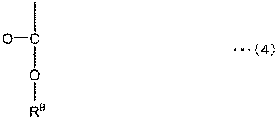
- In the formula (3), R6 and R7 may be the same or different and are each independently a hydrogen atom, an alkyl group, or an aromatic ring. In the formula (4), R8 is an alkyl group.
- In the present invention, the alkyl group is a straight-chain, branched, or cyclic alkyl group containing one to six carbon atoms, for example. Specific examples of the alkyl group include a methyl group, an ethyl group, a propyl group, an iso-propyl group, a butyl group, a tert-butyl group, a sec-butyl group, an iso-butyl group, a pentyl group, a neopentyl group, an isopentyl group, a sec-pentyl group, a tert-pentyl group, a cyclopentyl group, and a hexyl group.
- The structure of A that links the main chain and the benzene ring is not restricted, and may be, for example, a single bond, an ester bond, an ether bond, an amide bond, a thioether bond, a thioester bond, a urethane bond, or a functional group having an alkylene group. That is, the main chain and the benzene ring may be directly bonded in a single bond, or may be bonded via an ester bond, an ether bond, an amide bond, a thioether bond, a thioester bond, a urethane bond, or an alkylene group, or may be bonded via an ester bond, an ether bond, an amide bond, a thioether bond, a thioester bond, a urethane bond, or another functional group having an alkylene group.
- The photosoluble polymer more preferably includes a polymer represented by the following formula (5). In the following formula (5), monomers may be randomly polymerized or may be polymerized with regularity.

- In the formula (5), A and B may be the same or different and are each independently a single bond or a functional group, R3, R4, and R9 may be the same or different and are each independently a hydrogen atom or an alkyl group, R6 and R7 may be the same or different and are each independently a hydrogen atom, an alkyl group, or an aromatic ring, and x, y, and z represent mole percentages and satisfy 0 ≤ x < 100, 0 ≤ y < 100, and 0 ≤ z < 100 (except for x = y = 0), respectively.
- When R6 and R7 are each an alkyl group, R6 and R7 are each preferably an iso-propyl group or a tert- butyl group.
- It is preferable that x and y satisfy x > y so that cells can be processed more efficiently, for example. As to x, y, and z , x / (x + y + z) is preferably 0.04 or more.
- Examples of the polymers represented by the formula (2) or (5) include polymers represented by the formula (11) or (12) to be described below.
- Regarding the structures of A and B that link the main chain and the benzene ring, reference can be made to the description as to the structure of A that links the main chain and the benzene ring. The side chain linked by A can be generated, for example, by hydrolyzing an acetal group of the side chain linked by B. Therefore, it is preferable that the structures of A and B that link the main chain and the benzene ring be the same.
- Regarding the method for producing the photosoluble polymer, for example, reference can be made to the description of
WO 2017/013226 , which can be incorporated herein by reference. - The photothermal convertible polymer is a polymer which generates heat by light irradiation. Thus, in the case where the
photoreactive layer 12 includes the photothermal convertible polymer, when the cells C are cultured on thephotoreactive layer 12 as shown inFIG. 1C , heat is generated in thephotoreactive layer 12 by light irradiation, thereby killing the cell(s) C adjacent to thephotoreactive layer 12 irradiated with light, i.e., the cell(s) C directly above the light irradiated part. As a result, it is possible to release the fixation (adhesion) between the cells C that are indirectly adhered via the killed cell C. - The photothermal convertible polymer is, for example, a polymer having a chromophore that absorbs a wavelength of light to be irradiated. The photothermal convertible polymer has, for example, a main chain and a side chain, and the side chain has the chromophore. Examples of the chromophore include a compound having an azobenzene skeleton or a derivative thereof and derivatives of organic compounds such as diaryleton, spiropyran, spirooxazine, flugid, leuco dye, indigo, carotenoid (carotene, etc.), flavonoid (anthocyanin, etc.), quinoid (anthraquinone, etc.), and the like.
- The main chain can also be referred to as, for example, a skeleton constituting a polymer. Examples of the skeleton constituting the polymer include an acrylic polymer such as an acrylamide polymer, a polystyrene polymer, a polyolefin polymer, polyvinyl acetate, polyvinyl chloride, a polyolefin polymer, a polycarbonate polymer, and an epoxy polymer.
- The side chain preferably has a chromophore having a predetermined absorbance at a wavelength of 350 nm or more. The predetermined absorbance is, for example, 0.01 or more, and preferably 0.1 or more. The side chain preferably has an absorbance of 0.01 or more, preferably 0.1 or more, in a wavelength range of 350 nm or more and 1300 nm or less, for example. The absorbance can be measured using an absorbance meter. Examples of the chromophore having the predetermined absorbance include tar dyes such as an azo dye (e.g., dye having an azobenzene skeleton), a fluorescein dye, a leuco dye, a phenol dye, a polycyclic aromatic dye, indi-goid, and the like; and dyes having a natural dye skeleton such as carotenoid, flavonoid, a polyphyllin dye, an anthocyanin dye, an alizarin dye, a phycobilin dye, a quinone dye, and the like. Specific examples of the chromophore having the predetermined absorbance include Disperse Yellow 7 and Disperse Orange 3,4-(4-nitro-phenylazo)phenol.
- The chromophore is bonded directly or indirectly to the main chain, for example. In the direct bond, the aromatic ring is directly bonded to the main chain in a single bond. The indirect bond may be a bond via an ester bond, an ether bond, an amide bond, a thioether bond, a thioester bond, a urethane bond, or an alkylene group, or may be a bond via an ester bond, an ether bond, an amide bond, a thioether bond, a thioester bond, a urethane bond, or another functional group having an alkylene group, for example.
- Specific examples of the photothermal convertible polymer include polymers represented by the following formulae (8) to (10).


- In the formulae (8) to (10), m and n represent mole percentages and satisfy 0 < m ≤ 100 and 0 ≤ n < 100, respectively. In the formulae (8) to (10), the structure of azobenzene in the polymer may employ, besides an unsubstituted azobenzene, various variations of the structure modified with a nitro group, an amino group, a methyl group, or the like.
- The photothermal convertible polymer may be produced, for example, by reacting a functional group of a main chain constituting a photothermal convertible polymer with a functional group of the chromophore. Furthermore, the photothermal convertible polymer may be produced, for example, by polymerizing a monomer having a chromophore obtained by reacting a functional group of a monomer of the main chain with a functional group of the chromophore with a monomer of the main chain.
- The photosoluble and photothermal convertible polymer is a polymer having both characteristics of a photosoluble polymer and a photothermal convertible polymer. In the photosoluble and photothermal convertible polymer, an atomic group responsible for a photosolubility and an atomic group responsible for a photothermal convertibility exhibit their characteristics by light having different characteristics, for example. Specifically, for example, the atomic group responsible for a photosolubility and the atomic group responsible for a photothermal convertibility exhibit their characteristics by light of different energies (light irradiation amounts), and the atomic group responsible for a photothermal convertibility exhibits its characteristic by light of high energy as compared to the atomic group responsible for a photosolubility. Thus, by irradiating the
photoreactive layer 12 with light by which each atomic group exhibits its characteristic, it is possible to release the indirect fixation between the cells C and thesubstrate 11a due to the dissolution of the photosoluble and photothermal convertible polymer in thephotoreactive layer 12 and to release the fixation between the cells C indirectly adhered via the killed cell(s) C due to the killing of the cell(s) C. - The photosoluble and photothermal convertible polymer has a main chain and a side chain, the side chain has a first side chain and a second side chain, the first side chain is a side chain of the photosoluble polymer and the second side chain is a side chain of the photothermal convertible polymer, for example. Regarding the description of the side chain of the photosoluble polymer and the side chain of the photothermal convertible polymer, reference can be made to the above-described description.
- The photosoluble and photothermal convertible polymer preferably includes a polymer represented by the following formula (6). In the formula (6), monomers may be randomly polymerized or may be polymerized with regularity.

- In the formula (6), A and B may be the same or different and are each independently a single bond or a functional group, R3, R4, R9, and R10 may be the same or different and are each independently a hydrogen atom or an alkyl group, R6 and R7 may be the same or different and are each independently a hydrogen atom, an alkyl group, or an aromatic ring, D is a chromophore having a predetermined absorbance at a wavelength of 350 nm or more, and v, x, y, and z represent mole percentages and satisfy 0 < v < 100, 0 ≤ x < 100, 0 ≤ y < 100, and 0 ≤ z < 100 (except for x = y = 0), respectively.
- Examples of the polymers represented by the formula (6) include polymers represented by the formula (13) to be described below.
- The photosoluble and photothermal convertible polymer preferably includes a polymer represented by the following formula (7). In the following formula (7), monomers may be randomly polymerized or may be polymerized with regularity.

- In the formula (7), A, B, and E may be the same or different and are each independently a single bond or a functional group, R3, R4, R9, and R11 may be the same or different and are each independently a hydrogen atom or an alkyl group, R6 and R7 may be the same or different and are each independently a hydrogen atom, an alkyl group, or an aromatic ring, D is a chromophore having a predetermined absorbance at a wavelength of 350 nm or more, and u, x, y, and z represent mole percentages and satisfy 0 < u < 100, 0 ≤ x < 100, 0 ≤ y < 100, and 0 ≤ z < 100 (except for x = y = 0), respectively.
- Regarding the description of A, B, and substituents in the formulae (6) and (7), reference can be made to the descriptions as to the "(1) photosoluble polymer" and "(2) photothermal convertible polymer".
- The structure of E that links the main chain and a chromophore having a predetermined absorbance is not particularly restricted, and may be, for example, a single bond, an ester bond, an ether bond, an amide bond, a thioether bond, a thioester bond, a urethane bond, or a functional group having an alkylene group. That is, the main chain and the benzene ring may be directly bonded in a single bond, or may be bonded via an ester bond, an ether bond, an amide bond, a thioether bond, a thioester bond, a urethane bond, or an alkylene group, or may be bonded via an ester bond, an ether bond, an amide bond, a thioether bond, a thioester bond, a urethane bond, or another functional group having an alkylene group.
- The photosoluble and photothermal convertible polymer may be produced, for example, by reacting an aldehyde group of the photosoluble polymer with a functional group of the chromophore, or may be produced by polymerizing each monomer of the photosoluble polymer, a monomer of the main chain into which the chromophore is introduced, and a monomer of the main chain.
- The
photoreactive layer 12 may include other components besides the photoreactive polymer. Examples of the other components include photomeltable materials. The photomeltable material means, for example, a photoresponsive material capable of inducing solidification and liquefaction by light of different wavelengths. - A method for producing the
culture instrument 100 of the present embodiment includes, for example, a photoreactive layer forming step of forming thephotoreactive layer 12 on thesubstrate 11a. Thephotoreactive layer 12 may be formed by, for example, a known film forming method, and specific examples of the method include a coating method, a printing method (screen method), a vapor deposition method, a sputtering method, a casting method, and a spin coating method. When the photoreactive polymer in thephotoreactive layer 12 includes the photosoluble polymer and the photothermal convertible polymer, thephotoreactive layer 12 can be formed by mixing the photosoluble polymer and the photothermal convertible polymer and using the obtained mixture. When the photosoluble polymer and the photothermal convertible polymer are dispersed in a solvent, the method for producing theculture instrument 100 preferably includes a step of removing the solvent after forming thephotoreactive layer 12 on thesubstrate 11a. In the manner as described above, theculture instrument 100 of the present embodiment can be produced. - The
culture instrument 100 of the present embodiment may include, for example, a connection layer connecting thephotoreactive layer 12 and thesubstrate 11a. In this case, the connection layer is laminated on thesubstrate 11a and thephotoreactive layer 12 is laminated on the connection layer, i.e., the connection layer is disposed between thesubstrate 11a and thephotoreactive layer 12. By including the connection layer, theculture instrument 100 can maintain the responsiveness of thephotoreactive layer 12 even when long-term cell culture is performed so that the cells C can be excellently detached even after long-term culture, for example. - The connection layer includes, for example, a polymer having high hydration characteristic and rich in hydroxyl groups. As a specific example, the connection layer includes, for example, a crosslinked product of a cellulose derivative such as hydroxypropyl cellulose, hydroxybutyl cellulose, or the like, poly(hydroxyethyl methacrylate) and its copolymer. The crosslinked product of the cellulose derivative may be, for example, a product obtained by crosslinking hydroxypropyl cellulose with poly(ethylene glycol)bis(carboxymethyl) ether.
- When the
culture instrument 100 has the connection layer, the method for producing theculture instrument 100 of the present embodiment preferably includes a step of forming the connection layer on thesubstrate 11a prior to the photoreactive layer forming step. In the photoreactive layer forming step, thephotoreactive layer 12 is preferably formed on the connection layer. The connection layer can be formed in the same manner as the formation of thephotoreactive layer 12, for example. - The
culture instrument 100 of the present embodiment may include a cell culture base material layer on thephotoreactive layer 12, for example. In other words, the cell culture base material layer may be laminated on thephotoreactive layer 12. With such a configuration, theculture instrument 100 can favorably perform indirect fixation of the cells C to thesubstrate 11a, for example. Examples of the cell culture base material include an extracellular substrate (extracellular matrix) and a substance having a function as a cell scaffold. Examples of the extracellular substrate include elastin; entactin; collagens such as collagen I, collagen II, collagen III, collagen IV, collagen V, collagen VII, and the like; tenascin; fibrillin; fibronectin; laminin; vitronectin; proteoglycan composed of sulfated glucosaminoglycan such as chondroitin sulfate, heparan sulfate, keratan sulfate, dermatan sulfate, or the like and a core protein; glucosaminoglycans such as chondroitin sulfate, heparan sulfate, keratan sulfate, dermatan sulfate, hyaluronic acid, and the like; Synthemax® (vitronectin derivative); and Matrigel® (mixture of laminin, collagen IV, heparin sulfate proteoglycan, entactin/nidogen, and the like). Among them, laminin is preferable. The cell culture base material may include a peptide fragment of the protein or a fragment of the sugar chain. As a specific example, the peptide fragment of the protein may be a fragment of laminin. Examples of the fragment of laminin include laminin 211-E8, laminin 311-E8, laminin 411-E8, and laminin 511-E8. The laminin 211-E8 is composed of fragments of the α2, β1, and γ1 chains of laminin. The laminin 311-E8 is composed of fragments of the α3, β1, and γ1 chains of laminin. The laminin 411-E8 is composed of fragments of the α4, β1, and γ1 chains of laminin. The laminin 511-E8 is composed of fragments of the α5, β1, and γ1 chains of laminin, for example. - When the
culture instrument 100 includes the cell culture base material layer, the method for producing theculture instrument 100 of the present embodiment preferably includes a step of forming the cell culture base material layer on thephotoreactive layer 12 after the photoreactive layer forming step. The cell culture base material layer can be formed in the same manner as thephotoreactive layer 12, for example. - Next, a cell processing method using the
culture instrument 100 of the present embodiment will be described with reference toFIG. 2. FIG. 2 is a schematic view showing an example of a cell processing method using theculture instrument 100. As shown inFIG. 2 , in the processing method of the present embodiment, by irradiating theculture instrument 100 in which the cultured cells C are present with the first light (L1) and the second light (L2), the desired cells can be detached. - First, in the processing method of the present embodiment, as shown in (A) and (B) in
FIG. 2 , cells are cultured in the culture instrument 100 (culturing step). Cells to be cultured can be introduced, for example, by introducing a cell suspension into theculture instrument 100. The culture conditions (culture temperature, culture humidity, gas partial pressure, culture time, and the like) in the culturing step can be appropriately determined according to the type of the cells, for example. Specifically, the culture can be performed in a wet environment at 5% CO2 and 25 to 40 °C. - Next, the
photoreactive layer 12 is irradiated with first light (L1) that causes photodissolution (first irradiation step). More specifically, in the first irradiation step, thephotoreactive layer 12 corresponding to cells C1 to be processed (detached) among cells C is irradiated with L1, that is, thephotoreactive layer 12 immediately below the cells C1 to be processed is irradiated with L1. As a result, as shown in (C) inFIG. 2 , thephotoreactive layer 12 immediately below the cells C1 to be processed is dissolved, and the indirect fixation (adhesion) of the cells C1 to thesubstrate 11a is released. The wavelength of L1 is a wavelength at which an atomic group responsible for a photosolubility exhibits a photosolubility in the photoreactive polymer. As a specific example, the wavelength of L1 is, for example, 310 to 410 nm, preferably 350 to 410 nm or 360 to 370 nm. Further, the light irradiation amount (J/cm2) of L1 can be set as appropriate according to the wavelength of the light to be irradiated with and its energy amount, for example. As a specific example, when the wavelength of L1 is 365 nm, the light irradiation amount is, for example, 0.05 to 1 J/cm2, and is preferably 0.1 to 0.5 J/cm2. In addition, when the wavelength of L1 is 405 nm, the light irradiation amount is, for example, 0.5 to 10 J/cm2, and is preferably 1 to 5 J/cm2. While L1 is laser light, i.e., point light in the present embodiment, L1 is not limited thereto and may be planar light. - Next, the
photoreactive layer 12 is irradiated with second light (L2) that causes photothermal conversion (a second irradiation step). Specifically, in the second irradiation step, thephotoreactive layer 12 corresponding to the boundary between the cells C1 to be processed (detached) and the cells C2 not to be processed (detached) is irradiated with L2, that is, thephotoreactive layer 12 immediately below the cell C2 adjacent to the cells C1 to be processed among the cells C2 not to be processed is irradiated with L2. The boundary can also be referred to a region adjacent to the outer periphery of the region irradiated with L1, for example. As a result, as shown in (D) inFIG. 2 , the cell C2 adjacent to thephotoreactive layer 12 irradiated with L2 is killed, and the fixation between the cells C1 to be processed and the cells C2 not to be processed is released. Thus, as shown in (E) inFIG. 2 , the cells C1 to be processed become detachable. The killing may be induced upon irradiation with L2 or may be induced after irradiation with L2. The wavelength of L2 is a wavelength at which an atomic group (chromophore) responsible for a photothermal convertibility exhibits a photothermal convertibility in the photoreactive polymer. As a specific example, the wavelength of L2 is, for example, 300 nm or more, preferably 300 to 1300 nm, or 350 to 1300 nm. The wavelength of L2 may be the same as or different from the wavelength of L1, for example. Further, the light irradiation condition of L2 is, for example, a light irradiation amount with which the cells C adjacent to the part irradiated with L2 is killed, and the light irradiation condition can be set as appropriate according to the output of L2 to be irradiated with, the irradiation size (spot diameter) of L2, and the absorbance of the photoreactive layer at the irradiation wavelength of L2. As a specific example, when the output of the laser light is 0.6 W, the diameter (spot diameter) is 50 µm, and the absorbance of thephotoreactive layer 12 at the irradiation light wavelength (wavelength of the laser light) is 0.25, the scanning speed of the laser light can be set to 10 to 500 mm/sec, and preferably 50 to 200 mm/sec. The light irradiation condition of L2 may be appropriately changed based on the light irradiation condition. As a specific example, when the output of the laser light is doubled and the diameter of the laser light and the absorbance of thephotoreactive layer 12 are the same, the scanning speed of the laser light can be set to, for example, about twice, that is, 20 to 1000 mm/sec. In the second irradiation step, it preferable that the part irradiated with L2 be irradiated so as to temporarily or continuously increase the temperature to about 100 °C (e.g., 80 to 120°C). By setting the light irradiation conditions accordingly, the processing method of the present embodiment can effectively kill cells in the second irradiation step, for example. While L2 is laser light, i.e., point light in the present embodiment, L2 is not limited thereto and may be planar light. - In this manner, the processing method of the present embodiment can detach the cells C1 to be processed.
- In the present embodiment, since the second irradiation step is performed after the first irradiation step, the
photoreactive layer 12 immediately below the cell C2 adjacent to the cells C1 is irradiated with L2. However, the object to be irradiated with L2 is not limited thereto. In other words, in the processing method of the present embodiment, the first irradiation step may be performed after the second irradiation step, or these steps may be performed in parallel. As a specific example, when irradiation of L1 is performed after irradiation of L2, thephotoreactive layer 12 immediately below the cell C2 adjacent to the cells C1 to be processed or thephotoreactive layer 12 immediately below the cells C1 adjacent to the cells C2 not to be processed is irradiated with L2 in the second irradiation step, for example. In the first irradiation step, thephotoreactive layer 12 immediately below the cells C1 may be irradiated with L1. - While one cell C present at the boundary is killed in the processing method of the present embodiment, a plurality of cells C adjacent to the boundary may be killed. Thereby, the processing method of the present embodiment can effectively prevent, for example, that the cells C1 to be processed remain in the cells C2 not to be processed and that the cells C2 not to be processed are detached together with the cells C1 to be processed.
- The present embodiment is another example of a cell culture instrument and a cell processing method.
FIGs. 3A to 3C are schematic views showing the configuration of aculture instrument 200 of the second embodiment.FIG. 3A is a schematic perspective view of theculture instrument 200,FIG. 3B is a schematic cross-sectional view of theculture instrument 200 taken along line II-II ofFIG. 3A, and FIG. 3C is a schematic cross-sectional view of aculture instrument 200 taken along line II-II ofFIG. 3A in a state where cells are cultured in theculture instrument 200. As shown inFIGs. 3A to 3C , in theculture instrument 200, thephotoreactive layer 12 in the configuration of theculture instrument 100 of the first embodiment is composed of two layers. That is, thephotoreactive layer 12 includes a photothermalconvertible layer 12a and aphotosoluble layer 12b. Further, the photothermalconvertible layer 12a is laminated on thesubstrate 11a, and thephotosoluble layer 12b is laminated on the photothermalconvertible layer 12a. The cells C may be in contact with thephotosoluble layer 12b as shown inFIG. 3C or may be in contact with thephotosoluble layer 12b via another layer or the like. Except for this point, the configuration of theculture instrument 200 of the second embodiment is the same as that of theculture instrument 100 of the first embodiment, and reference can be made to the description thereof. - The photothermal
convertible layer 12a is a layer having a photothermal convertibility. That is, the photothermalconvertible layer 12a is a layer that generates heat by irradiation with light. The photothermalconvertible layer 12a includes the aforementioned photothermal convertible polymer. Regarding the photothermal convertible polymer, reference can be made to the description of "(2) photothermal convertible polymer" in the first embodiment. The photothermalconvertible layer 12a is formed on a part or the entire of the surface of thesubstrate 11a, for example. - The
photosoluble layer 12b is a layer having a photosolubility. In other words, thephotosoluble layer 12b is a layer whose solvent solubility is changed by light irradiation. Thephotosoluble layer 12b includes the aforementioned photosoluble polymer. Regarding the photosoluble polymer, reference can be made to the description of "(1) photosoluble polymer" in the first embodiment. - While the
photosoluble layer 12b is laminated on the photothermalconvertible layer 12a in theculture instrument 200, the order of laminating the photothermalconvertible layer 12a and the photothermal dissolvelayer 12b in theculture instrument 200 is not limited thereto, and the photothermalconvertible layer 12a may be laminated on thephotosoluble layer 12b. For example, by laminating thephotosoluble layer 12b on the photothermalconvertible layer 12a, theculture instrument 200 can easily detach the cells to be processed after the first irradiation step and the second irradiation step described below. - The
culture instrument 200 may include at least one of the aforementioned connection layer and cell culture base material layer, for example. When theculture instrument 200 includes the connection layer, the connection layer is laminated on thesubstrate 11a, and the photothermalconvertible layer 12a is laminated on the connection layer. When theculture instrument 200 includes the cell culture base material layer, the cell culture base material layer is laminated on thephotosoluble layer 12b. - The method for producing the
culture instrument 200 of the present embodiment includes, for example, a photothermal convertible layer forming step of forming the photothermalconvertible layer 12a on thesubstrate 11a, and a photosoluble layer forming step of forming thephotosoluble layer 12b on the photothermalconvertible layer 12a. The photothermalconvertible layer 12a and thephotosoluble layer 12b can be formed by, for example, a known film forming method, and reference can be made to the description of the method for forming thephotoreactive layer 12 in the first embodiment. In the manner as described above, theculture instrument 200 of the present embodiment can be produced. - Next, a cell processing method using the
culture instrument 200 of the present embodiment will be described with reference toFIG. 4. FIG. 4 is a schematic view showing an example of a cell processing method using theculture instrument 200. As shown inFIG. 4 , in the processing method of the present embodiment, by irradiating theculture instrument 200 in which the cultured cells C are present with the first light (L1) and the second light (L2), the desired cells can be detached. - First, in the processing method of the present embodiment, as shown in (A) and (B) in
FIG. 4 , cells are cultured in the culture instrument 200 (culturing step). Cells to be cultured can be introduced, for example, by introducing a cell suspension into theculture instrument 200. The culture conditions (culture temperature, culture humidity, gas partial pressure, culture time, and the like) in the culturing step can be appropriately determined according to the type of the cells, for example. Specifically, the culture can be performed in a wet environment at 5% CO2 and 25 to 40 °C. - Next, the
photosoluble layer 12b is irradiated with first light (L1) that causes photodissolution (first irradiation step). More specifically, in the first irradiation step, thephotosoluble layer 12b corresponding to cells C1 to be processed (detached) among cells C is irradiated with L1, that is, thephotosoluble layer 12b immediately below the cells C1 to be processed is irradiated with L1. As a result, as shown in (C) inFIG. 4 , thephotosoluble layer 12b immediately below the cells C1 to be processed is dissolved, and the indirect fixation (adhesion) of the cells C1 to thesubstrate 11a is released. The wavelength of L1 is a wavelength at which an atomic group responsible for a photosolubility exhibits a photosolubility in the photoreactive polymer. Regarding the specific examples of the wavelength and the light irradiation amount of L1, for example, reference can be made to the description of the first embodiment. While L1 is laser light, i.e., point light in the present embodiment, L1 is not limited thereto and may be planar light. - Next, the photothermal
convertible layer 12a is irradiated with second light (L2) that causes photothermal conversion (a second irradiation step). Specifically, in the second irradiation step, the photothermalconvertible layer 12a corresponding to the boundary between the cells C1 to be processed (detached) and the cells C2 not to be processed (detached) is irradiated with L2, that is, the photothermalconvertible layer 12a immediately below the cell C2 adjacent to the cells C1 to be processed among the cells C2 not to be processed is irradiated with L2. As a result, as shown in (D) inFIG. 4 , the cell C2 adjacent to the photothermalconvertible layer 12a irradiated with L2 is killed, and the fixation between the cells C1 to be processed and the cells C2 not to be processed is released. Thus, as shown in (E) inFIG. 4 , the cells C1 to be processed become detachable. The wavelength of L2 is a wavelength at which an atomic group (chromophore) responsible for a photothermal convertibility exhibits a photothermal convertibility in the photoreactive polymer. Regarding the specific examples of the wavelength and the light irradiation amount of L2, for example, reference can be made to the description of the first embodiment. The light irradiation amount of L2 may be, for example, the same as or different from the light irradiation amount of L1 and is preferably different from the light irradiation amount of L1. Further, the light irradiation amount of L2 is preferably larger than the light irradiation amount of L1. By setting the light irradiation amount accordingly, the processing method of the present embodiment can effectively kill cells, for example, in the second irradiation step. While L2 is laser light, i.e., point light in the present embodiment, L2 is not limited thereto and may be planar light. - In this manner, the processing method of the present embodiment can detach the cells C1 to be processed.
- In the present embodiment, since the second irradiation step is performed after the first irradiation step, the photothermal
convertible layer 12a immediately below the cell C2 adjacent to the cells C1 is irradiated with L2. However, the object to be irradiated with L2 is not limited thereto. In other words, in the processing method of the present embodiment, the first irradiation step may be performed after the second irradiation step, or these steps may be performed in parallel. As a specific example, when irradiation of L1 is performed after irradiation of L2, the photothermalconvertible layer 12a immediately below the cell C2 adjacent to the cells C1 to be processed or the photothermalconvertible layer 12a immediately below the cells C1 adjacent to the cells C2 not to be processed is irradiated with L2 in the second irradiation step, for example. In the first irradiation step, thephotosoluble layer 12b immediately below the cells C1 may be irradiated with L1. - While one cell C present at the boundary is killed in the processing method of the present embodiment, a plurality of cells C adjacent to the boundary may be killed. Thereby, the processing method of the present embodiment can effectively prevent, for example, that the cells C1 to be processed remain in the cells C2 not to be processed and that the cells C2 not to be processed are detached together with the cells C1 to be processed.
- Next, examples of the present invention will be described. The present invention, however, is not restricted by the following examples. Commercially available reagents were used based on their protocols unless otherwise indicated.
- The culture instrument of the present invention was produced and whether cells at a desired position can be detached by the processing method of the present invention was examined.
- The
culture instrument 100 of the first embodiment was prepared. First, as the photosoluble polymer, a polymer represented by the following formula (11) was synthesized. The polymer of the following formula (11) was synthesized by the same procedure as thecompound 12 ofWO 2017/013226 . Note that the introduction rate of the side chain (2-nitrobenzaldehyde) was 10 mol%. Further, as the photothermal convertible polymer, a polymer of the formula (8) was synthesized.
- Next, a 2,2,2-trifluoroethanol (TFE) solution containing 1.0% (w/w) photosoluble polymer and 0.085% (w/w) photothermal convertible polymer was prepared, and the obtained solution was spin-coated on the surface of the
substrate 11a made of polystyrene to form thephotoreactive layer 12. In this manner, the culture instrument 100 (Example 1) was produced. - MDCK cells (purchased from Riken BioResource Research Center) were dispersed in a medium and seeded into the
culture instrument 100 of Example 1 and cultured for half a day. As the medium for MDCK cells, a MEM medium containing 10% fetal bovine serum (FBS) was used. As to the culture conditions, the culture was performed at 5% CO2 and 37°C, and under a wet condition. After the culturing, the cells were checked to be adhered and extended throughout the surface of thesubstrate 11a. Then, L1 and L2 were emitted using a cell processing apparatus (produced by Kataoka Corporation) capable of emitting lasers from the bottom surface side (lower side inFIG. 1 ) of thesubstrate 11a toward the cells C on thephotoreactive layer 12. Specifically, as shown inFIG. 5A , thephotoreactive layer 12 immediately below the cells C1 to be processed was irradiated with L1. L1 was laser light having a wavelength of 405 nm, a diameter of 25 µm, and an energy intensity of 0.2 W, and scanning was performed in the range of a width of 0.6 mm at 20 µm pitch and a velocity of 1000 mm/s, thereby inducing the dissolution of thephotoreactive layer 12. Next, as shown inFIG. 5A , thephotoreactive layer 12 immediately below the cell C2 adjacent to the cells C1 among the cells C1 to be processed and the cells C2 not to be processed was irradiated with L2. L2 was laser light having a wavelength of 405 nm, a diameter of 25 µm, and an energy intensity of 0.8 W, and scanning was performed at a velocity of 300 mm/s. Irradiation with L2 was repeated 4 times to induce a cell monolayer to be killed. Theculture apparatus 100 was rotated by about 90°, and the irradiation with L1 and L2 was performed in the same manner. After the irradiation, theculture apparatus 100 was stored in an incubator for a while, and then the medium was lightly sprayed onto the surface thereof. As a result, the cells C1 to be processed were detached as shown inFIG. 5B . These results showed that, cells at a desired position can be detached using the culture instrument of the present invention by the processing method of the present invention. - The culture instrument of the present invention was produced and whether cells at a desired position can be detached by the processing method of the present invention was examined.
- A connection layer was provided between the
photoreactive layer 12 and thesubstrate 11a and a cell culture base material layer was laminated on thephotoreactive layer 12 in theculture instrument 100 of the first embodiment, thereby preparing a culture instrument. First, as the photosoluble polymer, the polymer of formula (11) synthesized in Example 1 (1) described above was used. Further, as the photothermal convertible polymer, a polymer of the formula (9) was synthesized. - First, a methanol solution containing 0.49% (w/w) hydroxypropylcellulose (MW = 100,000), 0.047% (w/w) poly(ethylene glycol)bis(carboxymethyl)ether (MW = 600), and 0.49 mol/kg sulfuric acid was prepared, and the obtained solution was spin-coated on the surface of the
substrate 11a made of polystyrene. Next, the obtained culture instrument was heated at 85 °C for 18 hours, washed with ethanol, and then dried. - After the drying, a TFE solution containing 1.9% (w/w) photosoluble polymer and 0.088% (w/w) photothermal convertible polymer was prepared, and the obtained solution was spin-coated on the surface of the
substrate 11a made of polystyrene. After the spin coating, the resultant was irradiated with ultraviolet light having a wavelength of 365 nm and an energy density of 0.9 mW/cm2 for 15 seconds, thereby forming thephotoreactive layer 12. - Next, using a diluted solution obtained by diluting 9.6 µL of iMatrix511 (produced by Nippi. Inc.) into 2 mL of PBS, a cell culture base material layer was formed in the culture instrument having the
photoreactive layer 12 according to the attached protocol. In this manner, a culture instrument (Example 2) was produced. - Human iPS cells (201B7 line, purchased from Riken BioResource Research Center) suspended in the medium were seeded into the culture instrument of Example 2 and cultured for 5 days. As a medium for the iPS cells, StemFitAK02N (Ajinomoto Co., Inc.) was used. As to the culture conditions, the culture was performed at 5% CO2 and 37°C, and under a wet condition. After the culturing, the cells were checked to be adhered and extended throughout the surface of the
substrate 11a. Then, L1 and L2 were emitted using the cell processing apparatus from the bottom surface side (lower side inFIG. 1 ) of thesubstrate 11a toward the cells C on thephotoreactive layer 12. Specifically, as shown inFIG. 6A , thephotoreactive layer 12 immediately below the cells C1 to be processed was irradiated with L1. L1 was laser light having a wavelength of 405 nm, a diameter of 25 µm, and an energy intensity of 0.2 W or 0.3 W, and scanning was performed once (in the case of 0.3 W) or twice (in the case of 0.2 W) in the range of a width of 0.6 mm at 10 µm pitch and a velocity of 1000 mm/s, thereby inducing the dissolution of thephotoreactive layer 12. Next, as shown inFIG. 6A , thephotoreactive layer 12 immediately below the cell C2 adjacent to the cells C1 among the cells C1 to be processed and the cells C2 not to be processed was irradiated with L2. L2 was laser light having a wavelength of 405 nm, a diameter of 25 µm, and an energy intensity of 0.8 W, and scanning was performed at a velocity of 200 mm/s to induce a cell monolayer to be killed. After the irradiation, theculture apparatus 100 was stored in an incubator for a while, and then the medium was lightly sprayed onto the surface thereof. As a result, the cells C1 to be processed were detached as shown inFIG. 6B . WhileFIG. 6B is a photograph in the case where L1 was 0.2 W, the detachment of the cells C1 to be processed was observed also in the case where L1 was 0.3 W. These results showed that, cells at a desired position can be detached using the culture instrument of the present invention by the processing method of the present invention. - The culture instrument of the present invention was produced and whether cells at a desired position can be detached by the processing method of the present invention was examined.
- The
culture instrument 100 of the first embodiment was prepared. First, as the photosoluble polymer, a polymer represented by the following formula (12) was synthesized. Further, as the photoreactive polymer (a polymer having a photosolubility and a photothermal convertibility), a polymer of the following formula (13) was synthesized using the polymer of the formula (12). The polymer of the formula (12) was synthesized by the same procedure as the synthetic procedure of thecompound 12 ofWO 2017/013226 except that N-tert-butylacrylamide was used instead of N-isopropylacrylamide. Note that the introduction rate of the side chain (2-nitrobenzaldehyde) was 19 mol%. Next, to a TFE solution containing the polymer of the formula (12) having a concentration of 1.8% (w/w), Disperse Orange 3 was added so as to achieve the concentration of 0.016% (w/w) and then stirred. As a result, the aldehyde group of the polymer of the formula (12) and the amino group of the Disperse Orange 3 reacted with each other, and the color of the solution changed from orange to purple, thereby synthesizing a polymer of the formula (13).

- Next, the obtained solution was spin-coated on the surface of the
substrate 11a made of polystyrene to form thephotoreactive layer 12. In this manner, a culture instrument 100 (Example 3-1) was produced. - Further, using a diluted solution obtained by diluting 0.2 µL of iMatrix511 (produced by Nippi. Inc.) into 1.5 mL of PBS, a cell culture base material layer was formed in the
culture instrument 100 of Example 3-1 according to the attached protocol. In this manner, a culture instrument (Example 3-2) was produced. - HeLa cells (purchased from Riken BioResource Research Center) were dispersed in a medium and seeded into the
culture instrument 100 of Example 3-1 and cultured for half a day. As the medium for HeLa cells, a MEM medium containing 10% FBS was used. As to the culture conditions, the culture was performed at 5% CO2 and 37°C, and under a wet condition. After the culturing, the cells were checked to be adhered and extended throughout the surface of thesubstrate 11a. Then, L1 and L2 were emitted using the cell processing apparatus from the bottom surface side (lower side inFIG. 1 ) of thesubstrate 11a toward the cells C on thephotoreactive layer 12. Specifically, as shown inFIG. 7A , thephotoreactive layer 12 immediately below the cells C1 to be processed was irradiated with L1. L1 was laser light having a wavelength of 405 nm, a diameter of 25 µm, and an energy intensity of 0.2 W or 0.3 W, and scanning was performed in the range of a width of 0.6 mm at 10 µm pitch and a velocity of 1000 mm/s, thereby inducing the dissolution of thephotoreactive layer 12. Next, as shown inFIG. 7A , thephotoreactive layer 12 immediately below the cell C2 adjacent to the cells C1 among the cells C1 to be processed and the cells C2 not to be processed was irradiated with L2. L2 was laser light having a wavelength of 405 nm, a diameter of 25 µm, and an energy intensity of 0.8 W, and scanning was performed at a velocity of 200 mm/s to induce a cell monolayer to be killed. After the irradiation, theculture apparatus 100 was stored in an incubator for a while, and then the medium was lightly sprayed onto the surface thereof. As a result, the cells C1 to be processed were detached as shown inFIG. 7B . WhileFIG. 7B is a photograph in the case where L1 was 0.2 W, the detachment of the cell C1 to be processed was observed also in the case where L1 was 0.3 W. - The human iPS cells suspended in a medium were seeded into the
culture instrument 100 of Example 3-2 and cultured under the same conditions as in Example 2 for 5 days. After the culturing, the cells were checked to be adhered and extended throughout the surface of thesubstrate 11a. Then, L1 and L2 were emitted using the cell processing apparatus from the bottom surface side (lower side inFIG. 1 ) of thesubstrate 11a toward the cells C on thephotoreactive layer 12. Specifically, as shown inFIG. 8A , thephotoreactive layer 12 immediately below the cells C1 to be processed was irradiated with L1. L1 was laser light having a wavelength of 405 nm, a diameter of 25 µm, and an energy intensity of 0.2 W or 0.3 W, and scanning was performed in the range of a width of 0.6 mm at 10 µm pitch and a velocity of 1000 mm/s, thereby inducing the dissolution of thephotoreactive layer 12. Next, as shown inFIG. 8A , thephotoreactive layer 12 immediately below the cell C2 adjacent to the cells C1 among the cells C1 to be processed and the cells C2 not to be processed was irradiated with L2. L2 was laser light having a wavelength of 405 nm, a diameter of 25 µm, and an energy intensity of 0.8 W, and scanning was performed at a velocity of 200 mm/s to induce a cell monolayer to be killed. After the irradiation, theculture apparatus 100 was stored in an incubator for a while, and then the medium was lightly sprayed onto the surface thereof. As a result, the cells C1 to be processed were detached as shown inFIG. 8B . WhileFIG. 8B is a photograph in the case where L1 was 0.2 W, the detachment of the cells C1 to be processed was observed also in the case where L1 was 0.3 W. These results showed that, cells at a desired position can be detached using the culture instrument of the present invention by the processing method of the present invention. - These results showed that, cells at a desired position can be detached using the culture instrument of the present invention by the processing method of the present invention.
- The culture instrument of the present invention was produced and whether cells at a desired position can be detached by the processing method of the present invention was examined.
- The
culture instrument 200 of the second embodiment was prepared. First, as the photothermal convertible polymer, the polymer of the formula (10) was synthesized. Specifically, 0.0035 g of 4-(4-nitrophenylazo)phenol and 0.008 g poly(glycidyl methacrylate) were dissolved in 0.457 g of acetone. To the obtained solution, 0.0086 g of 1,2-dichloroethane solution containing 2.8% (w/w) diazabicycloundecene (DBU) was added, and then stirred and reacted at 60 °C for 5 days. As a result, the color was changed from orange to deep red. This demonstrated that 4-(4-nitrophenylazo)phenol was introduced into the glycidyl group of poly(glycidyl methacrylate) and the polymer of the formula (10) was synthesized. As the photosoluble polymer, the polymer of the formula (12) synthesized in Example 3 (1) was used. - From the polymer solution of the formula (10), 0.164 g of the solution was fractionated and acetone was removed by nitrogen spraying, and the resultant was redissolved in 0.0478 g of TFE. Further, to the obtained solution, 0.0041 g of a TFE solution containing 0.05% (w/w) 1,12-diaminododecane was added, and then stirred. Next, the obtained solution was spin-coated on the surface of the
substrate 11a made of polystyrene, and then heated at 85 °C for 4 hours, and further washed with ethanol and re-dried to form the photothermalconvertible layer 12a. Next, a TFE solution containing the polymer of the formula (12) having a concentration of 1.8% (w/w) was spin-coated on the surface of the photothermalconvertible layer 12a, and then irradiated with ultraviolet light having a wavelength of 365 nm and an energy intensity of 1.5 mW/cm2 for 4 seconds, thereby producing theculture instrument 200. - HeLa cells were dispersed in a medium and seeded into the
culture instrument 200 of Example 4 and cultured for half a day. As the medium for HeLa cells, a MEM medium containing 10% FBS was used. As to the culture conditions, the culture was performed at 5% CO2 and 37°C, and under a wet condition. After the culturing, the cells were checked to be adhered and extended throughout the surface of thesubstrate 11a. Then, L1 and L2 were emitted using the cell processing apparatus from the bottom surface side (lower side inFIG. 3 ) of thesubstrate 11a toward the cells C on thephotoreactive layer 12. Specifically, as shown inFIG. 9A , thephotoreactive layer 12 immediately below the cells C1 to be processed was irradiated with L1. L1 was laser light having a wavelength of 405 nm, a diameter of 25 µm, and an energy intensity of 0.2 W or 0.3 W, and scanning was performed in the range of a width of 0.6 mm at 10 µm pitch and a velocity of 1000 mm/s, thereby inducing the dissolution of thephotoreactive layer 12. Next, as shown inFIG. 9A , thephotoreactive layer 12 immediately below the cell C2 adjacent to the cells C1 among the cells C1 to be processed and the cells C2 not to be processed was irradiated with L2. L2 was laser light having a wavelength of 405 nm, a diameter of 25 µm, and an energy intensity of 0.8 W, and scanning was performed twice at a velocity of 750 mm/s to induce a cell monolayer to be killed. After the irradiation, theculture apparatus 200 was stored in an incubator for a while, and then the medium was lightly sprayed onto the surface thereof. As a result, the cells C1 to be processed were detached as shown inFIG. 9B . WhileFIG. 9B is a photograph in the case where L1 was 0.2 W, the detachment of the cells C1 to be processed was observed also in the case where L1 was 0.3 W. These results showed that, cells at a desired position can be detached using the culture instrument of the present invention by the processing method of the present invention. - While the present invention has been described above with reference to illustrative embodiments, the present invention is by no means limited thereto. Various changes and variations that may become apparent to those skilled in the art may be made in the configuration and specifics of the present invention without departing from the scope of the present invention.
- This application claims priority from
Japanese Patent Application No. 2018-233382 filed on December 13, 2018 - Some or all of the above embodiments and examples may be described as in the following Supplementary Notes, but are not limited thereto.
- A cell culture instrument, including:
- a substrate; and
- a photoreactive layer having a photosolubility and a photothermal convertibility, wherein
- the photoreactive layer is laminated on the substrate, and
- the photoreactive layer includes a polymer having a photosolubility and a photothermal convertibility.
- The cell culture instrument according to Supplementary Note 1, wherein
- the photoreactive layer includes a photosoluble layer having a photosolubility and a photothermal convertible layer having a photothermal convertibility,
- the photosoluble layer includes a photosoluble polymer, and
- the photothermal convertible layer includes a photothermal convertible polymer.
- The cell culture instrument according to Supplementary Note 2, wherein
- the photosoluble polymer has a main chain and a side chain,
- the side chain has an aromatic ring,
- the aromatic ring includes a first carbon atom substituted with a nitro group and a second carbon atom substituted with an aldehyde group or a functional group represented by the following formula (1), and
- the first carbon atom and the second carbon atom are adjacent to each other within the same benzene ring.

- The cell culture instrument according to Supplementary Note 3, wherein
the photosoluble polymer includes a polymer represented by the following formula (2):
- A is a single bond or a functional group,
- R1 is an aldehyde group or a functional group represented by the formula (1),
- R1 and NO2 are each attached to adjacent carbon atoms,
- R2 is at least one selected from the group consisting of hydrogen atoms, alkyl groups, functional groups represented by the following formula (3), and functional groups represented by the following formula (4),
- R3 and R4 may be the same or different and are each independently a hydrogen atom or an alkyl group,
- G is three or less alkyl groups which may be substituted with hydrogen in a benzene ring, and
- w and z represent mole percentages and satisfy 0 < w ≤ 100 and 0 ≤ z < 100, respectively


- R6 and R7 may be the same or different and are each independently a hydrogen atom, an alkyl group, or an aromatic ring, and where in the formula (4),
- R8 is an alkyl group.
- The cell culture instrument according to Supplementary Note 3 or 4, wherein
the photosoluble polymer includes a polymer represented by the following formula (5):
- A and B may be the same or different and are each independently a single bond or a functional group,
- R3, R4, and R9 may be the same or different and are each independently a hydrogen atom or an alkyl group,
- R6 and R7 may be the same or different and are each independently a hydrogen atom, an alkyl group, or an aromatic ring, and x, y, and z represent mole percentages and satisfy 0 ≤ x < 100, 0 ≤ y < 100, and 0 ≤ z < 100 (except for x = y = 0), respectively.
- The cell culture instrument according to any one of Supplementary Notes 2 to 5, wherein
- the photothermal convertible polymer has a main chain and a side chain, and
- the side chain has a chromophore having a predetermined absorbance at a wavelength of 350 nm or more.
- The cell culture instrument according to Supplementary Note 6, wherein
the chromophore has an azobenzene skeleton. - The cell culture instrument according to Supplementary Note 1, wherein
- the polymer having a photosolubility and a photothermal convertibility has a main chain and a side chain,
- the side chain has a first side chain and a second side chain,
- the first side chain has an aromatic ring,
- the aromatic ring includes a first carbon atom substituted with a nitro group and a second carbon atom substituted with an aldehyde group or a functional group represented by the formula (1),
- the first carbon atom and the second carbon atom are adjacent to each other within the same benzene ring, and
- the second side chain has a chromophore having a predetermined absorbance at a wavelength of 350 nm or more.
- The cell culture instrument according to Supplementary Note 1 or 8, wherein
the polymer having a photosolubility and a photothermal convertibility is represented by the following formula (6):
- A and B may be the same or different and are each independently a single bond or a functional group,
- R3, R4, R9, and R10 may be the same or different and are each independently a hydrogen atom or an alkyl group,
- R6 and R7 may be the same or different and are each independently a hydrogen atom, an alkyl group, or an aromatic ring,
- D is a chromophore having a predetermined absorbance at a wavelength of 350 nm or more, and
- v, x, y, and z represent mole percentages and satisfy 0 < v < 100, 0 ≤ x < 100, 0 ≤ y < 100, and 0 ≤ z < 100 (except for x = y = 0), respectively.
- The cell culture instrument according to Supplementary Note 1, wherein
the polymer having a photosolubility and a photothermal convertibility is represented by the following formula (7):
- A, B, and E may be the same or different and are each independently a single bond or a functional group,
- R3, R4, R9, and R11 may be the same or different and are each independently a hydrogen atom or an alkyl group,
- R6 and R7 may be the same or different and are each independently a hydrogen atom, an alkyl group, or an aromatic ring,
- D is a chromophore having a predetermined absorbance at a wavelength of 350 nm or more, and
- u, x, y, and z represent mole percentages and satisfy 0 < u < 100, 0 ≤ x < 100, 0 ≤ y < 100, and 0 ≤ z < 100 (except for x = y = 0), respectively.
- The cell culture instrument according to any one of Supplementary Notes 1 to 10, including:
- a connection layer connecting the photoreactive layer and the substrate, wherein
- the connection layer is laminated on the substrate, and
- the photoreactive layer is laminated on the connection layer.
- The cell culture instrument according to any one of Supplementary Notes 1 to 11, wherein
cells can be cultured on the photoreactive layer. - A cell processing method, including:
- a culturing step of culturing cells in the cell culture instrument according to any one of Supplementary Notes 1 to 12;
- a first irradiation step of irradiating the photoreactive layer with first light that causes photodissolution; and
- a second irradiation step of irradiating the photoreactive layer with second light that causes photothermal conversion.
- The cell processing method according to Supplementary Note 13, wherein
- in the first irradiation step, a photoreactive layer corresponding to cells to be processed among the cells is irradiated with the first light, and
- in the second irradiation step, a photoreactive layer corresponding to a boundary between the cells to be processed and cells not to be processed among the cells is irradiated with the second light.
- The cell processing method according to Supplementary Note 13 or 14, wherein
in the second irradiation step, a cell corresponding to the photoreactive layer irradiated with the second light is killed. - The cell processing method according to any one of Supplementary Notes 13 to 15, wherein
the light irradiation amount of the second light is larger than the light irradiation amount of the first light. - According to the present invention, cells at a desired position can be detached. For this reason, the present invention is extremely useful in a life science field, a medical field, or the like, which performs processing of cells, tissues, and the like.
-
- 100, 200: culture instrument
- 11: container
- 11a: substrate
- 11b: side wall
- 12: photoreactive layer
- 12a: photothermal convertible layer
- 12b: photosoluble layer
Claims (15)
- A cell culture instrument, comprising:a substrate; anda photoreactive layer having a photosolubility and a photothermal convertibility, whereinthe photoreactive layer is laminated on the substrate, andthe photoreactive layer comprises a polymer having a photosolubility and a photothermal convertibility.
- The cell culture instrument according to claim 1, whereinthe photoreactive layer comprises a photosoluble layer having a photosolubility and a photothermal convertible layer having a photothermal convertibility,the photosoluble layer comprises a photosoluble polymer, andthe photothermal convertible layer comprises a photothermal convertible polymer.
- The cell culture instrument according to claim 2, whereinthe photosoluble polymer has a main chain and a side chain,the side chain has an aromatic ring,the aromatic ring includes a first carbon atom substituted with a nitro group and a second carbon atom substituted with an aldehyde group or a functional group represented by the following formula (1), andthe first carbon atom and the second carbon atom are adjacent to each other within the same benzene ring.

- The cell culture instrument according to claim 3, wherein
the photosoluble polymer includes a polymer represented by the following formula (2): A is a single bond or a functional group,R1 is an aldehyde group or a functional group represented by the formula (1),R1 and NO2 are each attached to adjacent carbon atoms,R2 is at least one selected from the group consisting of hydrogen atoms, alkyl groups, functional groups represented by the following formula (3), and functional groups represented by the following formula (4),R3 and R4 may be the same or different and are each independently a hydrogen atom or an alkyl group,G is three or less alkyl groups which may be substituted with hydrogen in a benzene ring, andw and z represent mole percentages and satisfy 0 < w ≤ 100 and 0 ≤ z < 100, respectively
 R6 and R7 may be the same or different and are each independently a hydrogen atom, an alkyl group, or an aromatic ring, andwhere in the formula (4),R8 is an alkyl group.
 - The cell culture instrument according to claim 3 or 4, wherein the photosoluble polymer comprises a polymer represented by the following formula (5):
 A and B may be the same or different and are each independently a single bond or a functional group,R3, R4, and R9 may be the same or different and are each independently a hydrogen atom or an alkyl group,R6 and R7 may be the same or different and are each independently a hydrogen atom, an alkyl group, or an aromatic ring, andx, y, and z represent mole percentages and satisfy 0 ≤ x < 100, 0 ≤ y < 100, and 0 ≤ z < 100 (except for x = y = 0), respectively.
 - The cell culture instrument according to any one of claims 2 to 5, whereinthe photothermal convertible polymer has a main chain and a side chain, andthe side chain has a chromophore having a predetermined absorbance at a wavelength of 350 nm or more.
- The cell culture instrument according to claim 6, wherein the chromophore has an azobenzene skeleton.
- The cell culture instrument according to claim 1, wherein
the polymer having a photosolubility and a photothermal convertibility is represented by the following formula (6): A and B may be the same or different and are each independently a single bond or a functional group,R3, R4, R9, and R10 may be the same or different and are each independently a hydrogen atom or an alkyl group,R6 and R7 may be the same or different and are each independently a hydrogen atom, an alkyl group, or an aromatic ring,D is a chromophore having a predetermined absorbance at a wavelength of 350 nm or more, andv, x, y, and z represent mole percentages and satisfy 0<v<100, 0 ≤ x < 100, 0 ≤y < 100, and 0 ≤ z < 100 (except for x = y = 0), respectively.
 - The cell culture instrument according to claim 1, wherein
the polymer having a photosolubility and a photothermal convertibility is represented by the following formula (7): A, B, and E may be the same or different and are each independently a single bond or a functional group,R3, R4, R9, and R11 may be the same or different and are each independently a hydrogen atom or an alkyl group,R6 and R7 may be the same or different and are each independently a hydrogen atom, an alkyl group, or an aromatic ring,D is a chromophore having a predetermined absorbance at a wavelength of 350 nm or more, andu, x, y, and z represent mole percentages and satisfy 0 < u < 100, 0 ≤ x < 100, 0 ≤ y < 100, and 0 ≤ z < 100 (except for x = y = 0), respectively.
 - The cell culture instrument according to any one of claims 1 to 9, comprising:a connection layer connecting the photoreactive layer and the substrate, whereinthe connection layer is laminated on the substrate, andthe photoreactive layer is laminated on the connection layer.
- The cell culture instrument according to any one of claims 1 to 10, wherein
cells can be cultured on the photoreactive layer. - A cell processing method, comprising:a culturing step of culturing cells in the cell culture instrument according to any one of claims 1 to 11 ;a first irradiation step of irradiating the photoreactive layer with first light that causes photodissolution; anda second irradiation step of irradiating the photoreactive layer with second light that causes photothermal conversion.
- The cell processing method according to claim 12, whereinin the first irradiation step, a photoreactive layer corresponding to cells to be processed among the cells is irradiated with the first light, andin the second irradiation step, a photoreactive layer corresponding to a boundary between the cells to be processed and cells not to be processed among the cells is irradiated with the second light.
- The cell processing method according to claim 12 or 13, wherein
in the second irradiation step, a cell corresponding to the photoreactive layer irradiated with the second light is killed. - The cell processing method according to any one of claims 12 to 14, wherein
the light irradiation amount of the second light is larger than the light irradiation amount of the first light.
Applications Claiming Priority (2)
| Application Number | Priority Date | Filing Date | Title |
|---|---|---|---|
| JP2018233382 | 2018-12-13 | ||
| PCT/JP2019/048865 WO2020122225A1 (en) | 2018-12-13 | 2019-12-13 | Cell culture tool and cell treatment method |
Publications (2)
| Publication Number | Publication Date |
|---|---|
| EP3896099A1 true EP3896099A1 (en) | 2021-10-20 |
| EP3896099A4 EP3896099A4 (en) | 2022-01-19 |
Family
ID=71076461
Family Applications (1)
| Application Number | Title | Priority Date | Filing Date |
|---|---|---|---|
| EP19894692.3A Pending EP3896099A4 (en) | 2018-12-13 | 2019-12-13 | CELL CULTURE TOOL AND CELL PROCESSING METHOD |
Country Status (5)
| Country | Link |
|---|---|
| US (1) | US12270020B2 (en) |
| EP (1) | EP3896099A4 (en) |
| JP (1) | JP7554428B2 (en) |
| CN (1) | CN113166313B (en) |
| WO (1) | WO2020122225A1 (en) |
Families Citing this family (1)
| Publication number | Priority date | Publication date | Assignee | Title |
|---|---|---|---|---|
| JP7554428B2 (en) * | 2018-12-13 | 2024-09-20 | 国立研究開発法人産業技術総合研究所 | Cell culture device and cell processing method |
Family Cites Families (17)
| Publication number | Priority date | Publication date | Assignee | Title |
|---|---|---|---|---|
| JP3699994B2 (en) | 2001-11-21 | 2005-09-28 | 独立行政法人産業技術総合研究所 | Light wettability controlled film and method for producing the same |
| JP3975266B2 (en) * | 2002-05-24 | 2007-09-12 | 独立行政法人産業技術総合研究所 | Cell culture equipment |
| JP5396803B2 (en) | 2008-10-06 | 2014-01-22 | コニカミノルタ株式会社 | Cell culture substrate and cell culture method |
| JPWO2011058721A1 (en) * | 2009-11-13 | 2013-03-28 | 株式会社日立ハイテクノロジーズ | Cell adhesion light control substrate, cell analysis and separation method, and cell analysis and separation device |
| EP2554657B1 (en) | 2010-04-02 | 2019-02-20 | National Institute of Advanced Industrial Science And Technology | Method for separating cells, cell culture medium, and device for separating cells |
| JP5879942B2 (en) * | 2011-11-08 | 2016-03-08 | 大日本印刷株式会社 | Cell culture substrate manufacturing method, cell culture substrate, and cell sheet manufacturing method using the same |
| CN104987471B (en) * | 2013-10-11 | 2017-09-19 | 天津大学 | Preparation method of high-strength light-sensitive hydrogel |
| US10876086B2 (en) * | 2015-06-01 | 2020-12-29 | Kataoka Corporation | Cell treatment method, laser processing machine, and cell culture vessel |
| JP6680479B2 (en) * | 2015-06-29 | 2020-04-15 | 株式会社片岡製作所 | Cell processing method, laser processing machine |
| EP3323878A4 (en) | 2015-07-16 | 2019-03-27 | Daikin Industries, Ltd. | CONTAINER FOR ADMINISTRATION, STORAGE OR CULTURE OF CELLS |
| US10358269B2 (en) | 2015-07-22 | 2019-07-23 | Nestec S.A. | Hinged closure for a container |
| JP6033980B1 (en) * | 2016-06-01 | 2016-11-30 | 株式会社片岡製作所 | Cell processing system |
| US11566093B2 (en) * | 2016-06-08 | 2023-01-31 | National Institute Of Advanced Industrial Science And Technology | Polymer compound and method for manipulating cell using same |
| WO2019035436A1 (en) * | 2017-08-16 | 2019-02-21 | 東ソー株式会社 | Culture substrate for pluripotent stem cell and method for producing pluripotent stem cell |
| JP6732313B2 (en) * | 2018-10-01 | 2020-07-29 | 株式会社片岡製作所 | Cell culture instrument and method of manufacturing cell culture instrument |
| EP3848450A4 (en) * | 2018-10-01 | 2022-06-29 | Kataoka Corporation | Cell culture tool and method for manufacturing cell culture tool |
| JP7554428B2 (en) * | 2018-12-13 | 2024-09-20 | 国立研究開発法人産業技術総合研究所 | Cell culture device and cell processing method |
-
2019
- 2019-12-13 JP JP2020559334A patent/JP7554428B2/en active Active
- 2019-12-13 EP EP19894692.3A patent/EP3896099A4/en active Pending
- 2019-12-13 WO PCT/JP2019/048865 patent/WO2020122225A1/en not_active Ceased
- 2019-12-13 US US17/312,620 patent/US12270020B2/en active Active
- 2019-12-13 CN CN201980081707.0A patent/CN113166313B/en active Active
Also Published As
| Publication number | Publication date |
|---|---|
| CN113166313B (en) | 2023-06-06 |
| US20220073862A1 (en) | 2022-03-10 |
| JPWO2020122225A1 (en) | 2021-10-21 |
| EP3896099A4 (en) | 2022-01-19 |
| WO2020122225A1 (en) | 2020-06-18 |
| JP7554428B2 (en) | 2024-09-20 |
| US12270020B2 (en) | 2025-04-08 |
| CN113166313A (en) | 2021-07-23 |
Similar Documents
| Publication | Publication Date | Title |
|---|---|---|
| Nelson et al. | Photoinduced dithiolane crosslinking for multiresponsive dynamic hydrogels | |
| Lee et al. | Photoresponsive hydrogels with photoswitchable mechanical properties allow time-resolved analysis of cellular responses to matrix stiffening | |
| Scheutz et al. | Harnessing strained disulfides for photocurable adaptable hydrogels | |
| EP2330182A1 (en) | Spheroid composite, spheroid-containing hydrogel and processes for production of same | |
| JP6056111B2 (en) | Photodegradable cross-linking agent, photodegradable gel, cell culture instrument, cell arrangement / sorting device, cell arrangement method, cell sorting method, tissue body forming method, and tissue body | |
| JP5496488B2 (en) | Cell pattern collection tool | |
| JP6580221B2 (en) | Medical device, cell culture method, and fluorine-containing cyclic olefin polymer composition | |
| Zhiganshina et al. | Tetramethacrylic benzylidene cyclopentanone dye for one-and two-photon photopolymerization | |
| CN112752836A (en) | Cell culture device and method for manufacturing cell culture device | |
| JP5388092B2 (en) | Spheroid-containing hydrogel, method for producing the same, and spheroid-containing hydrogel laminate | |
| US12270020B2 (en) | Cell culture instrument and cell processing method | |
| CN116693487A (en) | Coumarin-based thioester photoinitiator suitable for photopolymerization and preparation method thereof | |
| Duymaz et al. | Effect of Photoinitiation Process on Photo‐Crosslinking of Gelatin Methacryloyl Hydrogel Networks | |
| Ho et al. | Printing of woodpile scaffold using fresnel lens for tissue engineering | |
| JP2013099282A (en) | Cell culture container and cultured cell recovery method | |
| Lu et al. | Substituent effect on the visible light initiating ability of chalcones | |
| Zhou et al. | Comparative photoinitiating performances of donor–acceptor multibranched triphenylamines designed for light-triggered micropatterning applications | |
| EP3848450A1 (en) | Cell culture tool and method for manufacturing cell culture tool | |
| CN106543428B (en) | Aggretion type ultra-violet absorber of the side group containing UV-0 and preparation method thereof | |
| Du et al. | Type II photoinitiators with collagen-based cyanine for cell encapsulation under green-red LED | |
| Paciello et al. | A supramolecular two-photon-active hydrogel platform for direct bioconjugation under near-infrared radiation | |
| CN117683221A (en) | Aliphatic polycarbonate adhesive containing photoresponsive groups and preparation method thereof | |
| JP2013099285A (en) | Method for producing cell culture container | |
| JP2017201891A (en) | Substrate for cell culture, production method thereof, and method for controlling physical properties of substrate for cell culture | |
| Gernhardt | Multi-material microstructures with novel stimuli-responsive properties |
Legal Events
| Date | Code | Title | Description |
|---|---|---|---|
| STAA | Information on the status of an ep patent application or granted ep patent |
Free format text: STATUS: THE INTERNATIONAL PUBLICATION HAS BEEN MADE |
|
| PUAI | Public reference made under article 153(3) epc to a published international application that has entered the european phase |
Free format text: ORIGINAL CODE: 0009012 |
|
| STAA | Information on the status of an ep patent application or granted ep patent |
Free format text: STATUS: REQUEST FOR EXAMINATION WAS MADE |
|
| 17P | Request for examination filed |
Effective date: 20210615 |
|
| AK | Designated contracting states |
Kind code of ref document: A1 Designated state(s): AL AT BE BG CH CY CZ DE DK EE ES FI FR GB GR HR HU IE IS IT LI LT LU LV MC MK MT NL NO PL PT RO RS SE SI SK SM TR |
|
| A4 | Supplementary search report drawn up and despatched |
Effective date: 20211217 |
|
| RIC1 | Information provided on ipc code assigned before grant |
Ipc: G03F 7/004 20060101ALI20211213BHEP Ipc: C09D 133/20 20060101ALI20211213BHEP Ipc: C08L 33/20 20060101ALI20211213BHEP Ipc: C08F 220/54 20060101ALI20211213BHEP Ipc: C12N 1/02 20060101ALI20211213BHEP Ipc: C12M 3/00 20060101ALI20211213BHEP Ipc: C12M 1/28 20060101ALI20211213BHEP Ipc: C08F 20/56 20060101AFI20211213BHEP |
|
| DAV | Request for validation of the european patent (deleted) | ||
| DAX | Request for extension of the european patent (deleted) | ||
| STAA | Information on the status of an ep patent application or granted ep patent |
Free format text: STATUS: EXAMINATION IS IN PROGRESS |
|
| 17Q | First examination report despatched |
Effective date: 20220817 |
|
| REG | Reference to a national code |
Ref country code: DE Ref legal event code: R079 Free format text: PREVIOUS MAIN CLASS: C08F0020560000 Ipc: C12M0001000000 |
|
| RIC1 | Information provided on ipc code assigned before grant |
Ipc: C08L 33/20 20060101ALI20250204BHEP Ipc: C09D 133/20 20060101ALI20250204BHEP Ipc: C08F 220/54 20060101ALI20250204BHEP Ipc: G03F 7/20 20060101ALI20250204BHEP Ipc: G03F 7/105 20060101ALI20250204BHEP Ipc: G03F 7/095 20060101ALI20250204BHEP Ipc: G03F 7/039 20060101ALI20250204BHEP Ipc: C12M 1/26 20060101ALI20250204BHEP Ipc: C12M 1/00 20060101AFI20250204BHEP |
|
| RAP1 | Party data changed (applicant data changed or rights of an application transferred) |
Owner name: NATIONAL INSTITUTE OF ADVANCED INDUSTRIALSCIENCE AND TECHNOLOGY |
|
| GRAP | Despatch of communication of intention to grant a patent |
Free format text: ORIGINAL CODE: EPIDOSNIGR1 |
|
| STAA | Information on the status of an ep patent application or granted ep patent |
Free format text: STATUS: GRANT OF PATENT IS INTENDED |