EP3896025B1 - Boom type vehicle - Google Patents
Boom type vehicle Download PDFInfo
- Publication number
- EP3896025B1 EP3896025B1 EP21161907.7A EP21161907A EP3896025B1 EP 3896025 B1 EP3896025 B1 EP 3896025B1 EP 21161907 A EP21161907 A EP 21161907A EP 3896025 B1 EP3896025 B1 EP 3896025B1
- Authority
- EP
- European Patent Office
- Prior art keywords
- boom
- counterweight
- type vehicle
- vertical swing
- work platform
- Prior art date
- Legal status (The legal status is an assumption and is not a legal conclusion. Google has not performed a legal analysis and makes no representation as to the accuracy of the status listed.)
- Active
Links
Images


Classifications
-
- B—PERFORMING OPERATIONS; TRANSPORTING
- B66—HOISTING; LIFTING; HAULING
- B66F—HOISTING, LIFTING, HAULING OR PUSHING, NOT OTHERWISE PROVIDED FOR, e.g. DEVICES WHICH APPLY A LIFTING OR PUSHING FORCE DIRECTLY TO THE SURFACE OF A LOAD
- B66F11/00—Lifting devices specially adapted for particular uses not otherwise provided for
- B66F11/04—Lifting devices specially adapted for particular uses not otherwise provided for for movable platforms or cabins, e.g. on vehicles, permitting workmen to place themselves in any desired position for carrying out required operations
- B66F11/044—Working platforms suspended from booms
- B66F11/046—Working platforms suspended from booms of the telescoping type
-
- B—PERFORMING OPERATIONS; TRANSPORTING
- B66—HOISTING; LIFTING; HAULING
- B66C—CRANES; LOAD-ENGAGING ELEMENTS OR DEVICES FOR CRANES, CAPSTANS, WINCHES, OR TACKLES
- B66C23/00—Cranes comprising essentially a beam, boom, or triangular structure acting as a cantilever and mounted for translatory of swinging movements in vertical or horizontal planes or a combination of such movements, e.g. jib-cranes, derricks, tower cranes
- B66C23/06—Cranes comprising essentially a beam, boom, or triangular structure acting as a cantilever and mounted for translatory of swinging movements in vertical or horizontal planes or a combination of such movements, e.g. jib-cranes, derricks, tower cranes with jibs mounted for jibbing or luffing movements
- B66C23/08—Cranes comprising essentially a beam, boom, or triangular structure acting as a cantilever and mounted for translatory of swinging movements in vertical or horizontal planes or a combination of such movements, e.g. jib-cranes, derricks, tower cranes with jibs mounted for jibbing or luffing movements and adapted to move the loads in predetermined paths
- B66C23/10—Cranes comprising essentially a beam, boom, or triangular structure acting as a cantilever and mounted for translatory of swinging movements in vertical or horizontal planes or a combination of such movements, e.g. jib-cranes, derricks, tower cranes with jibs mounted for jibbing or luffing movements and adapted to move the loads in predetermined paths the paths being substantially horizontal; Level-luffing jib-cranes
- B66C23/14—Cranes comprising essentially a beam, boom, or triangular structure acting as a cantilever and mounted for translatory of swinging movements in vertical or horizontal planes or a combination of such movements, e.g. jib-cranes, derricks, tower cranes with jibs mounted for jibbing or luffing movements and adapted to move the loads in predetermined paths the paths being substantially horizontal; Level-luffing jib-cranes with means, e.g. pantograph arrangements, for varying jib configuration
-
- B—PERFORMING OPERATIONS; TRANSPORTING
- B66—HOISTING; LIFTING; HAULING
- B66C—CRANES; LOAD-ENGAGING ELEMENTS OR DEVICES FOR CRANES, CAPSTANS, WINCHES, OR TACKLES
- B66C23/00—Cranes comprising essentially a beam, boom, or triangular structure acting as a cantilever and mounted for translatory of swinging movements in vertical or horizontal planes or a combination of such movements, e.g. jib-cranes, derricks, tower cranes
- B66C23/62—Constructional features or details
- B66C23/72—Counterweights or supports for balancing lifting couples
-
- B—PERFORMING OPERATIONS; TRANSPORTING
- B66—HOISTING; LIFTING; HAULING
- B66F—HOISTING, LIFTING, HAULING OR PUSHING, NOT OTHERWISE PROVIDED FOR, e.g. DEVICES WHICH APPLY A LIFTING OR PUSHING FORCE DIRECTLY TO THE SURFACE OF A LOAD
- B66F17/00—Safety devices, e.g. for limiting or indicating lifting force
- B66F17/006—Safety devices, e.g. for limiting or indicating lifting force for working platforms
Definitions
- the present invention relates to a boom type working vehicle which has a boom mounted vertically swingable on a vehicle body, in which a working apparatus, such as a work platform on which an operator can board or a hoisting apparatus capable of hanging a baggage, is attached to the boom.
- a working apparatus such as a work platform on which an operator can board or a hoisting apparatus capable of hanging a baggage
- a boom In a boom type vehicle such as a vehicle with an aerial work platform or a mobile crane, a boom is provided on a rotating superstructure which can be rotated, and a working apparatus (a hoisting apparatus composed of a hook and a winch, a work platform, or the like) attached to the boom raises and lowers an operator or a baggage (hereinafter referred to as an "operator or others").
- a counterweight is attached to the rotating superstructure to keep a balance with a load to be applied to a tip end portion when the boom is made to stand to raise the operator or others.
- an articulating boom type vehicle with an aerial work platform described in the specification in U.S. Patent No.
- 5669517 comprises three section Z-shaped articulating boom provided with a work platform, and a counterweight is attached to an arm in a section closest to a vehicle body among three sections.
- a vehicle with an aerial work platform described in Japanese Laid-Open Patent Publication No. 2001-146396(A ) includes a chassis having wheels, a turret (rotating body) provided to be rotatable on the chassis, a boom provided to be vertically swingable on the turret, and a work platform attached to the boom.
- a link mechanism is attached to the rear of a vertical swing center of the boom, and the link mechanism is coupled to the counterweight provided on the turret.
- a counterweight that generates a stable moment is provided on a rotating superstructure to ensure stability when a boom is made to stand to raise an operator or others.
- an overturn moment may be generated by the counterweight provided on the rotating superstructure depending on geography (specifically, inclination) at a stop position of the boom type vehicle, a direction of the rotating superstructure, and an upright position of the boom.
- a counterweight can also be provided on the vehicle body side.
- the weight of the entire boom type vehicle increases, which is not preferable when a load burden on a vehicle body, a deterioration in traveling performance, and the like are considered.
- the present invention has been made in view of such a problem, and is directed to providing a boom type vehicle in which an overturn moment is not easily generated by a counterweight when a boom stands.
- a boom type vehicle comprises a traveling body that can travel, a rotating superstructure that is provided to be rotatable on the traveling body, a boom that is provided to be vertically swingable on the rotating superstructure over a vertical swing center of the boom a working apparatus (e.g., a work platform 40 in the embodiment) provided on the boom, and a counterweight provided on the boom, in which the counterweight is fixed to a rear end of the boom, wherein the boom type vehicle further comprises a link mechanism that is configured to move the boom from a laid flat state towards an upright state, and by which movement the vertical swing center of the boom is moved closer to the swing center of the rotating superstructure and the vertical swing center of the boom is raised from its position in the laid flat state.
- the rotating superstructure preferably includes a protective member (e.g., a bumper 25 in the embodiment) that protects side and rear portions of the counterweight from outside in a range where the counterweight moves with a vertical swing operation of the boom from the laid flat state to an upright state.
- a protective member e.g., a bumper 25 in the embodiment
- the working apparatus may be a work platform on which an operator can board, or may be a hoisting apparatus that can rise and lower a baggage hung.
- a counterweight is provided on a boom, and a center of gravity of the counterweight is closer to a rear end of the boom than a vertical swing center of the boom.
- the center of gravity of the counterweight moves toward the vertical swing center of the boom as the boom stands.
- an overturn moment by the counterweight is not more easily generated than when the counterweight is fixed to a rotating superstructure.
- the boom type vehicle having the above-described configuration includes a link mechanism that moves, when the boom stands from a laid flat state, the vertical swing center of the boom to come closer to a swing center of the rotating superstructure while more raising the vertical swing center of the boom than a position in the laid flat state.
- the boom can be moved such that a position of the counterweight does not come closer to the ground while the counterweight moves as the boom stands.
- a ground clearance of the boom in the laid flat state can be reduced.
- the length of the boom required to raise a working apparatus to a predetermined height can be shortened by a rise amount of the vertical swing center of the boom.
- the boom type vehicle having any one of the configurations preferably includes a protective member that protects side and rear portions of the counterweight from outside in a range where the counterweight moves with a vertical swing operation of the boom from the laid flat state to an upright state.
- a protective member that protects side and rear portions of the counterweight from outside in a range where the counterweight moves with a vertical swing operation of the boom from the laid flat state to an upright state.
- the vehicle with an aerial work platform 1 comprises a traveling body 10 configured to be able to travel, a rotating superstructure 20 provided on an upper portion of the traveling body 10 and rotatable in a horizontal direction, a boom 30 provided on an upper portion of the rotating superstructure 20 and vertically swingable, an articulating arm 45 provided on a tip end portion of the boom 30, and a work platform 40 attached to the articulating arm 45.
- the traveling body 10 has a pair of left and right steering wheels 12 (a left steering wheel 12L and a right steering wheel 12R) and a pair of left and right driving wheels 13 (a left driving wheel 13L and a right driving wheel 13R) that are rotatably provided on a traveling body frame 11.
- the left driving wheel 13L and the right riving wheel 13R are driven to rotate by a traveling motor 16 illustrated in FIG. 3 .
- the left steering wheel 12L and the right steering wheel 12R are configured to be caused to perform a steering operation (steering angle displacement operation) by the steering mechanism 60.
- the steering mechanism 60 is constituted by left and right steering brackets that respectively rotatably support the left steering wheel 12L and the right steering wheel 12R, a tie rod that couples the left and right steering brackets to each other, a steering cylinder 66 (see FIG. 3 ) that causes the left and right steering brackets to perform a steering operation, and the like.
- a rod of the steering cylinder 66 performs an extension or contraction operation from a neutral position
- the left and right steering brackets are interlockedly steered by the tie rod.
- a steering angle of the steering wheel 12 is displaced.
- rightward movement and leftward movement in the figure of the travelling body 10 are respectively referred to as "forward movement" and "rearward movement”.
- a rotation mechanism 15 is provided at an upper center of the traveling body frame 11.
- the rotation mechanism 15 is configured to rotate the rotating superstructure 20 around a rotation axis TA illustrated in FIG. 1(b) .
- the rotation mechanism 15 includes an outer wheel gear fixed to the traveling body frame 11, an inner pinion gear engaging with the outer wheel gear and fixed to the rotating superstructure 20, and a rotary center joint (not illustrated) for supplying hydraulic oil to various types of actuators (described below) provided on the rotating superstructure 20.
- the rotating superstructure 20 has a rotating superstructure housing 21 (see FIG. 2 ) and a rotating superstructure chassis 22. In FIGs. 1(a) and 1(b) , the rotating superstructure housing 21 is indicated by a broken line.
- the rotating superstructure housing 21 houses various types of components constituting a hydraulic circuit, for example, a hydraulic pump, an engine as its driving source, and various types of valves.
- the rotating superstructure chassis 22 pivotably supports a driving link 23 and a driven link 24 that are pivotably connected to the boom 30. More specifically, a driving support shaft DLP pivotably supports one end of the driving link 23, and a driven support shaft FLP supports one end of the driven link 24.
- a bumper 25 for protecting a counterweight 37 is provided on the rearward side of the rotating superstructure 20. As illustrated in FIG. 1(a) , a width Wb of the bumper 25 is wider than a width Wc of the counterweight 37. An end of the bumper 25 in a rearward direction of the traveling body 10 is longer by a length D than an end of the counterweight 37.
- the width of the rotating superstructure housing 21 is also the same dimension as the width Wb of the bumper 25, and thus is wider than the width Wc of the counterweight 37.
- the boom 30 is provided via the driving link 23 and the driven link 24, described above, on an upper part of the rotating superstructure 20.
- the boom 30 includes a base boom 31 and an intermediate boom 32 and a top boom 33 combined with the base boom 31 in a telescopic form.
- the base boom 31 side (the left side in FIG. 1 ) is referred to as a rearward side
- the top boom 33 side (the right side in FIG. 1 ) is a forward side.
- the counterweight 37 is fixed to a rear part of the base boom 31, and an articulating arm 45 is provided ahead of the top boom 31.
- the base boom 31 is pivotably connected to the other end of the driving link 23 in a driving link pivotable connection shaft DPC, and is pivotably connected to the other end of the driven link 24 in a vertical swing center shaft UDC.
- the counterweight 37 is fixed closer to a rear end of the base boom 31 than the vertical swing center shaft UDC of the base boom 31.
- a cylinder support shaft SP (see FIGs. 4 and 5 ) is provided between the driving link pivotable connection shaft DPC and the driving support shaft DLP in the driving link 23, and is pivotably connected to a main body of a boom vertical swing cylinder 35.
- a tip end of a cylinder rod of the boom vertical swing cylinder 35 is pivotably connected to a cylinder support shaft SPC provided on the boom 30.
- a work platform 40 that can be boarded by an operator M is provided at a tip end of the articulating arm 45.
- the work platform 40 has a work floor 41 having a substantially rectangular shape that can be boarded by the operator M and a handrail 42 provided to stand around the work floor 41.
- the work platform 40 is provided with an operation apparatus 70 (see FIG. 3 ) that performs traveling control of the traveling body 10 and operation control of the boom 30, or the like.
- the control apparatus controls various types of actuators that operate the traveling body 10, the rotating superstructure 20, the boom 30, the articulating arm 45, and the work platform 40, and comprises the operation apparatus 70 provided on the work platform 40, a hydraulic unit 80 that supplies hydraulic oil to the various types of actuators as a driving source of the various types of actuators, and a controller 50 that controls hydraulic oil to be supplied to the various types of actuators from the hydraulic unit 80 in response to an operation for various types of operation levers in the operation apparatus 70.
- the controller 50 is installed inside the rotating superstructure housing 21.
- Examples of the actuator related to traveling control among the actuators provided on the vehicle with an aerial work platform 1 include a traveling motor 16 that causes the traveling body 10 to move forward or move rearward in a predetermined speed range, a steering cylinder 66 that causes the steering wheel 12 to perform a steering operation, and a brake cylinder 18 that brakes the traveling body 10 during traveling.
- Examples of the actuator related to movement control of the work platform 40 include a rotation motor 26, a boom vertical swing cylinder 35, a boom axial extension cylinder 36, a horizontal swing motor 46, an articulating cylinder 47, and a leveling cylinder 48.
- the traveling motor 16 transmits rotation of a motor shaft to be driven by hydraulic pressure of hydraulic oil to be supplied to the driving wheel 13 (see FIG. 1 ) and normally or reversely rotates the motor shaft to normally or reversely rotate the driving wheel 13, thereby causing the traveling body 10 (see FIG. 1 ) to move forward or move rearward.
- a rotational speed of the motor shaft is controlled, to change a traveling speed of the traveling body 10.
- the brake cylinder 18 is a negative brake that brakes and locks the rotation of the motor shaft of the traveling motor 16 with a force of a contained spring and brakes the rotation of the driving wheel 13 when not supplied with hydraulic oil.
- the tip end of the cylinder rod of the steering cylinder 66 is connected to the steering mechanism 60 (see FIG. 1(a) ), and the steering cylinder 66 extends and contracts to cause the steering wheel 12 to perform a steering operation.
- the rotation motor 26 is provided on the rotating superstructure 20, and transmits rotation of its motor shaft to the inner pinion gear engaging with the outer wheel gear fixed to the traveling body frame 11 and normally or reversely rotates the rotation motor 26, to swing the rotating superstructure 20 in a clockwise or counterclockwise direction with respect to the traveling body 10.
- the boom vertical swing cylinder 35 is provided astride between the driving link 23 and the boom 30, and causes the cylinder rod to extend and contract to vertically swing the boom 30 with the vertical swing center shaft UDC used as a center.
- the boom axial extension cylinder 36 is provided in the boom 30, and the boom axial extension cylinder 36 is made to extend and contract, to cause the intermediate boom 32 and the top boom 33 that are combined with the base boom 31 in a telescopic form to extend and contract with respect to the base boom 31.
- the horizontal swing motor 46 is provided on the work platform 40, and causes the work platform 40 to perform a swing operation (horizontal swing operation) in a direction indicated by an arrow A illustrated in FIG. 1(a) by rotation of a motor shaft to be driven by hydraulic pressure of hydraulic oil to be supplied.
- the articulating arm 45 is formed of a parallel link mechanism including a leveling bracket 45a pivotably connected to a tip end portion of the top boom 33 to be vertically swingable and a first arm 45c and a second arm 45d having their respective one ends pivotably connected to the leveling bracket 45a to be vertically swingable and having respective other ends pivotably connected to a head bracket 45b that supports the work platform 40 to be vertically swingable.
- the articulating arm 45 is provided with the articulating cylinder 47 (see FIG. 3 ) between the first arm 45c and the second arm 45d, and is configured to be able to vertically swing the articulating arm 45 with respect to the leveling bracket 45a by causing the articulating cylinder 47 to perform an extension and contraction operation.
- the leveling cylinder 48 is provided between the top boom 33 and the leveling bracket 45a, and by extending and contracting the leveling cylinder 48, the leveling bracket 45a is controlled to always hold a predetermined angular posture with respect to a vehicle body regardless of a vertical swing angle position of the boom 30. As a result, an angular posture of the head bracket 45b is always kept constant by a function of the parallel link mechanism including the first arm 45c and the second arm 45d.
- the hydraulic unit 80 that supplies hydraulic oil as a driving source that operates the various types of actuators, described above, includes an engine E provided on the rotating superstructure 20, a hydraulic pump P to be driven by the engine E, a hydraulic oil tank T, and a control valve unit 85 that controls a supply direction and a supply amount of hydraulic oil to be supplied to each of the hydraulic actuators from the hydraulic pump P.
- the control valve unit 85 includes a plurality of control valves respectively provided to correspond to the hydraulic actuators.
- the plurality of control valves include a traveling control valve V1 that controls driving of the traveling motor 16, a brake control valve V2 that controls the brake cylinder 18, a steering direction switching valve V3 that controls the steering cylinder 66, a swing control valve V4, a vertical swing control valve V5, an axial extension control valve V6, a horizontal swing control valve V7, an articulating control valve V8, and a leveling control valve V9.
- the operation apparatus 70 constituting the control apparatus illustrated in FIG. 3 includes a traveling operation lever 71 that performs start and stop, forward movement and rearward movement, and traveling speed switching, for example, of the traveling body 10, a steering lever 72 that performs a steering operation of the traveling body 10 (a steering operation of the steering wheel 12), a rotation operation lever 73 that performs a swing operation of the rotating superstructure 20, a boom operation lever 74 that performs vertical swing and axial extension operations of the boom 30, a work platform operation lever 75 that performs a horizontal swing operation (swing operation) of the work platform 40, and an articulating arm operation lever 76 that performs a bend and stretch operation of the articulating arm 45.
- a traveling operation lever 71 that performs start and stop, forward movement and rearward movement, and traveling speed switching, for example, of the traveling body 10
- a steering lever 72 that performs a steering operation of the traveling body 10 (a steering operation of the steering wheel 12)
- a rotation operation lever 73 that performs a swing operation of the rotating
- Each of the operation levers is configured to be positioned at a neutral position where a direction of the lever is a vertical posture and to be operable to be tilted in a direction determined depending on the operation lever with the neutral position used as a reference when the operation lever remains non-operated.
- the controller 50 controls the control valves in the control valve unit 85 in response to an tilting operation to be performed by the operator of each of the above-described operation levers.
- the traveling operation lever 71 is operable to be tilted in a front-rear direction from the neutral position.
- the controller 50 controls a spool movement direction and a valve opening of the traveling control valve V1 such that the traveling body 10 moves forward at a speed corresponding to an tilting angle of the lever, to control a supply direction and a flow rate of hydraulic oil to be supplied to the traveling motor 16.
- the controller 50 controls the spool movement direction and the valve opening of the traveling control valve V1 such that the supply direction of hydraulic oil to be supplied to the traveling motor 16 is opposite to that when the traveling operation lever 71 is operated to be tilted forward, to control the supply direction and the flow rate of hydraulic oil such that the traveling body 10 moves rearward at a speed corresponding to an tilting angle of the lever.
- the controller 50 brings the brake control valve V2 into an open state, to supply hydraulic oil to the brake cylinder 18.
- a braked and locked state is released so that the motor shaft enters a rotatable state.
- the controller 50 brings the brake control valve V2 into a closed state, to stop supplying hydraulic oil to the brake cylinder 18.
- the motor shaft of the traveling motor 16 enters the braked and locked state, to brake rotation of the driving wheel 13.
- the steering lever 72 is operable to be tilted in a left-right direction from the neutral position, and the controller 50 displaces the steering angle of the steering wheel 12 such that the traveling body 10 turns left when it moves forward with the lever operated to be tilted leftward and the traveling body 10 turns right when it moves forward with the lever operated to be tilted rightward.
- the steering operation of the steering wheel 12 is performed when the controller 50 controls a spool movement direction and a valve opening of the steering direction switching valve V3.
- the rotation operation lever 73 is configured to be operable to be tilted in a left-right direction from the neutral position, and the controller 50 controls a spool movement direction and a valve opening of the swing control valve V4 to drive the rotation motor 26 such that the rotating superstructure 20 rotates in a clockwise direction with the swing axis TA illustrated in FIG. 1(b) used as a center when the lever is operated to be tilted rightward and rotates in a counterclockwise direction with the swing axis TA used as a center when the lever is operated to be tilted leftward.
- the boom operation lever 74 is configured to be operable to be tilted in left-right and front-rear directions from the neutral position.
- the controller 50 switches a spool movement direction of the axial extension control valve V6 depending on an tilting direction of the operation lever and controls a valve opening of the axial extension control valve V6 to a predetermined valve opening, to drive the boom axial extension cylinder 36 to cause the boom 30 to perform an extension and contraction operation.
- the controller 50 switches a spool movement direction of the vertical swing control valve V5 depending on an tilting direction of the lever and controls a valve opening of the vertical swing control valve V5 to a predetermined valve opening, to drive the boom vertical swing cylinder 35 to cause the boom 30 to perform a vertical swing operation.
- the vertical swing operation lever and the axial extension operation lever may be separately provided to perform the vertical swing operation of the boom 30 by an tilting operation in a front-rear direction of the vertical swing operation lever and perform the extension and contraction operation of the boom 30 by an tilting operation in a front-rear direction of the axial extension operation lever.
- the controller 50 controls a spool movement direction and a valve opening of the leveling control valve V9 such that the work platform 40 moves downward (in a clockwise direction) in an arrow B illustrated in FIG. 1(b) to hold a horizontal state of the work floor 41 to match the vertical swing operation of the boom 30.
- the controller 50 controls the spool movement direction and the valve opening of the leveling control valve V9 such that the work platform 40 moves upward (in a counterclockwise direction) in the arrow B illustrated in FIG. 1(b) to hold a horizontal state of the work floor 41 to match the vertical swing operation of the boom 30.
- the work platform operation lever 75 is configured to be operable to be tilted in a left-right direction from the neutral position.
- the controller 50 controls a spool movement direction and a valve opening of the horizontal swing control valve V7 such that the work platform 40 performs a horizontal swing operation in a counterclockwise direction in the direction indicated by the arrow A illustrated in FIG. 1(a) when the lever is operated to be tilted rightward.
- the controller 50 controls the spool movement direction and the valve opening of the horizontal swing control valve V7 such that the work platform 40 performs a horizontal swing operation in a clockwise direction in the direction indicated by the arrow A illustrated in FIG. 1(a) .
- the controller 50 controls a spool movement direction and a valve opening of the articulating control valve V8 in response to an operation of the articulating arm operation lever 76 to cause the articulating cylinder 47 to extend and contract, to cause the articulating arm 45 to perform a vertical bend and stretch operation with respect to the boom 30.
- FIG. 4(a) illustrates a laid flat state of the base boom 31. In this state, the cylinder rod of the boom vertical swing cylinder 35 contracts, and the base boom 31 is inclined more downward than the horizontal.
- the cylinder rod of the boom vertical swing cylinder 35 further extends, and the base boom 31 is inclined upward from the horizontal with the vertical swing center shaft UDC used as a center, as illustrated in FIG. 4(c) .
- the driving link 23 and the driven link 24 are further turned in a clockwise direction with the driving support shaft DLP and the driven support shaft FLP respectively used as centers.
- the respective positions of the vertical swing center shaft UDC and the driving link pivotable connection shaft DPC further move upward to the right in the figure.
- the counterweight 37 comes closer to the swing axis TA of the rotating superstructure 20 beyond the bumper 25.
- FIG. 5 illustrates a base boom 31', a vertical swing center shaft UDC', and a counterweight 37' in the laid flat state illustrated in FIG. 4(a) , respectively, by broken lines.
- a trajectory of the vertical swing center shaft UDC that moves while the base boom 31 shifts from the laid flat state to the upright state is indicated by an arrow C.
- a position of the vertical swing center shaft UDC is the highest in the upright state of the base boom 31, and the vertical swing center shaft UDC comes closest to the swing axis TA so that the counterweight 37 can be brought closer to the swing axis TA. Accordingly, an overturn moment by the counterweight 37 can be made difficult to generate while a weight balance with the work platform 40 is kept.
- the vertical swing center shaft UDC follows a trajectory indicated by the arrow C illustrated in FIG. 5 while the base boom 31 reaches the upright state from the laid flat state by the driving link 23 and the driven link 24.
- the counterweight 37 can be brought closer to the swing axis TA without a height from the ground of the counterweight 37 being greatly changed.
- a position of the vertical swing center shaft UDC is the highest in the upright state of the base boom 31. Accordingly, the length of the boom 30 required to raise the work platform 40 to a predetermined height can be shortened.
- an end of the bumper 25 in the rearward direction of the traveling body 10 is longer by the length D than the end of the counterweight 37.
- the counterweight 37 moves to a position indicated by a solid line from a position indicated by a broken line while the base boom 31 shifts from the laid flat state to the upright state.
- the respective widths of the bumper 25 and the rotating superstructure housing 21 are wider than the width Wc of the counterweight 37 (see FIG. 1(a) ).
- the bumper 25 and the rotating superstructure housing 21 enable the counterweight 37, the boom 30, the driving link 23, the driven link 24, and the like to be protected not to contact a wall surface or the like when the rotating superstructure is performing a swing operation.
- the rotating superstructure chassis 22" is provided with a boom support 27 that supports the boom 30 to be vertically swingable, and is pivotably connected to a vertical swing center shaft UDC" of a base boom 31", as illustrated in FIG. 6 .
- a cylinder rod of the boom vertical swing cylinder 35" is pivotably connected by a cylinder pivotable connection shaft SPC" of the base boom 31", and a body end portion of the boom vertical swing cylinder 35" is pivotably connected by a cylinder support shaft SP" provided on the boom support 27.
- a counterweight 37" can be brought closer to the swing axis TA in the rotating superstructure 20 as the base boom 31 shifts from a horizontal state (indicated by a broken line in FIG. 6 ) to an upright state.
- the present invention is not limited to the above-described embodiment, but can be appropriately improved without departing from the scope of the present invention.
- the vehicle with an aerial work platform 1 in which the tip end portion of the top boom 32 is provided with the articulating arm 45 and the work platform 40 is illustrated in the present embodiment, for example, the present invention is also applicable to a crane truck comprising a hoisting apparatus including a hook that hangs a baggage, a wire connected to the hook, and a hoisting apparatus capable of hoisting the wire instead of the work platform.
Landscapes
- Engineering & Computer Science (AREA)
- Mechanical Engineering (AREA)
- Structural Engineering (AREA)
- Life Sciences & Earth Sciences (AREA)
- Geology (AREA)
- Forklifts And Lifting Vehicles (AREA)
- Jib Cranes (AREA)
Description
- The present invention relates to a boom type working vehicle which has a boom mounted vertically swingable on a vehicle body, in which a working apparatus, such as a work platform on which an operator can board or a hoisting apparatus capable of hanging a baggage, is attached to the boom.
- In a boom type vehicle such as a vehicle with an aerial work platform or a mobile crane, a boom is provided on a rotating superstructure which can be rotated, and a working apparatus (a hoisting apparatus composed of a hook and a winch, a work platform, or the like) attached to the boom raises and lowers an operator or a baggage (hereinafter referred to as an "operator or others"). In the boom type vehicle, generally a counterweight is attached to the rotating superstructure to keep a balance with a load to be applied to a tip end portion when the boom is made to stand to raise the operator or others. For example, an articulating boom type vehicle with an aerial work platform described in the specification in
U.S. Patent No. 5669517 comprises three section Z-shaped articulating boom provided with a work platform, and a counterweight is attached to an arm in a section closest to a vehicle body among three sections. As a result, when the articulating boom operates to raise the work platform, the counterweight, together with movement of the arm, shifts in a direction away from an overturn support point. Accordingly, a weight balance with the work platform can be kept. - A vehicle with an aerial work platform described in
Japanese Laid-Open Patent Publication No. 2001-146396(A US 3 196979 discloses the preamble ofclaim 1 and describes a boom type vehicle wherein the distal end of the boom is provided with a workman cage or aerial basket. The boom can be vertically swung over a hinging connection (pivot pin) which is arranged in a fixed position on the turret which can be swivelled in the horizontal plane over pedestal. The pivot pin which functions as a vertical swing center for the boom, is not simultaneously movable in two combined directions. In particular, the height of the pivot pin and the distance to the swivelling axis of the turret does not alter during the vertical swinging of the boom. - Conventionally, in a boom type vehicle, a counterweight that generates a stable moment is provided on a rotating superstructure to ensure stability when a boom is made to stand to raise an operator or others. However, an overturn moment may be generated by the counterweight provided on the rotating superstructure depending on geography (specifically, inclination) at a stop position of the boom type vehicle, a direction of the rotating superstructure, and an upright position of the boom. To counteract the overturn moment generated by the counterweight, a counterweight can also be provided on the vehicle body side. However, in this case, the weight of the entire boom type vehicle increases, which is not preferable when a load burden on a vehicle body, a deterioration in traveling performance, and the like are considered.
- The present invention has been made in view of such a problem, and is directed to providing a boom type vehicle in which an overturn moment is not easily generated by a counterweight when a boom stands.
- To solve the above-described problem, a boom type vehicle according to the present invention comprises a traveling body that can travel, a rotating superstructure that is provided to be rotatable on the traveling body, a boom that is provided to be vertically swingable on the rotating superstructure over a vertical swing center of the boom a working apparatus (e.g., a
work platform 40 in the embodiment) provided on the boom, and a counterweight provided on the boom, in which the counterweight is fixed to a rear end of the boom, wherein the boom type vehicle further comprises a link mechanism that is configured to move the boom from a laid flat state towards an upright state, and by which movement the vertical swing center of the boom is moved closer to the swing center of the rotating superstructure and the vertical swing center of the boom is raised from its position in the laid flat state. - In the boom type vehicle having the above-described configuration, the rotating superstructure preferably includes a protective member (e.g., a
bumper 25 in the embodiment) that protects side and rear portions of the counterweight from outside in a range where the counterweight moves with a vertical swing operation of the boom from the laid flat state to an upright state. - In the boom type vehicle having any one of the configurations, the working apparatus may be a work platform on which an operator can board, or may be a hoisting apparatus that can rise and lower a baggage hung.
- In a boom type vehicle according to the present invention, a counterweight is provided on a boom, and a center of gravity of the counterweight is closer to a rear end of the boom than a vertical swing center of the boom. Thus, the center of gravity of the counterweight moves toward the vertical swing center of the boom as the boom stands. As a result, an overturn moment by the counterweight is not more easily generated than when the counterweight is fixed to a rotating superstructure.
- The boom type vehicle having the above-described configuration includes a link mechanism that moves, when the boom stands from a laid flat state, the vertical swing center of the boom to come closer to a swing center of the rotating superstructure while more raising the vertical swing center of the boom than a position in the laid flat state. As a result, the boom can be moved such that a position of the counterweight does not come closer to the ground while the counterweight moves as the boom stands. Thus, a ground clearance of the boom in the laid flat state can be reduced. The length of the boom required to raise a working apparatus to a predetermined height can be shortened by a rise amount of the vertical swing center of the boom.
- The boom type vehicle having any one of the configurations preferably includes a protective member that protects side and rear portions of the counterweight from outside in a range where the counterweight moves with a vertical swing operation of the boom from the laid flat state to an upright state. As a result, even if the rotating superstructure contacts a wall surface or the like when performing a swing operation, for example, the counterweight, the boom, and the like can be protected.
- Further scope of applicability of the present invention will become apparent from the detailed description given hereinafter. However, it should be understood that the detailed description and specific examples, while indicating preferred embodiments of the invention, are given by way of illustration only, since various changes and modifications within the scope of the claims will become apparent to those skilled in the art from this detailed description.
- The present invention will become more fully understood from the detailed description given herein below and the accompanying drawings which are given by way of illustration only and thus are not limitative of the present invention.
-
FIG. 1 is a diagram illustrating an appearance of a boom type vehicle according to the present invention, whereFIG. 1(a) is a plan view of a vehicle with an aerial work platform, andFIG. 1(b) is a side view of the vehicle with an aerial work platform; -
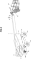
FIG. 2 is a perspective view illustrating an appearance of the boom type vehicle; -
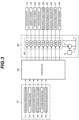
FIG. 3 is a block diagram illustrating an operation control configuration of the boom type vehicle; -
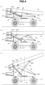
FIG. 4 is a side view illustrating how a vertical swing operation of a boom provided on the boom type vehicle is performed; -
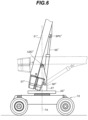
FIG. 5 is a side view illustrating an upright state of the boom provided on the boom type vehicle; and -
FIG. 6 is a side view illustrating an appearance in another embodiment of the boom type vehicle according to the present invention. - An embodiment of the present invention will be described below with reference to the drawings. As an example of a boom type vehicle according to the present invention, an appearance of a self-propelled vehicle with an
aerial work platform 1 is illustrated inFIGS. 1 and2 . As illustrated inFIGs. 1 and2 , the vehicle with anaerial work platform 1 comprises a travelingbody 10 configured to be able to travel, a rotatingsuperstructure 20 provided on an upper portion of the travelingbody 10 and rotatable in a horizontal direction, aboom 30 provided on an upper portion of the rotatingsuperstructure 20 and vertically swingable, an articulatingarm 45 provided on a tip end portion of theboom 30, and awork platform 40 attached to the articulatingarm 45. - The traveling
body 10 has a pair of left and right steering wheels 12 (aleft steering wheel 12L and aright steering wheel 12R) and a pair of left and right driving wheels 13 (a leftdriving wheel 13L and a right drivingwheel 13R) that are rotatably provided on a travelingbody frame 11. The leftdriving wheel 13L and the right rivingwheel 13R are driven to rotate by a travelingmotor 16 illustrated inFIG. 3 . Theleft steering wheel 12L and theright steering wheel 12R are configured to be caused to perform a steering operation (steering angle displacement operation) by thesteering mechanism 60. Thesteering mechanism 60 is constituted by left and right steering brackets that respectively rotatably support theleft steering wheel 12L and theright steering wheel 12R, a tie rod that couples the left and right steering brackets to each other, a steering cylinder 66 (seeFIG. 3 ) that causes the left and right steering brackets to perform a steering operation, and the like. When a rod of thesteering cylinder 66 performs an extension or contraction operation from a neutral position, the left and right steering brackets are interlockedly steered by the tie rod. As a result, a steering angle of thesteering wheel 12 is displaced. In the present embodiment, as illustrated inFIG. 1(b) , rightward movement and leftward movement in the figure of thetravelling body 10 are respectively referred to as "forward movement" and "rearward movement". - A
rotation mechanism 15 is provided at an upper center of thetraveling body frame 11. Therotation mechanism 15 is configured to rotate therotating superstructure 20 around a rotation axis TA illustrated inFIG. 1(b) . Therotation mechanism 15 includes an outer wheel gear fixed to the travelingbody frame 11, an inner pinion gear engaging with the outer wheel gear and fixed to the rotatingsuperstructure 20, and a rotary center joint (not illustrated) for supplying hydraulic oil to various types of actuators (described below) provided on the rotatingsuperstructure 20. The rotatingsuperstructure 20 has a rotating superstructure housing 21 (seeFIG. 2 ) and a rotatingsuperstructure chassis 22. InFIGs. 1(a) and 1(b) , the rotatingsuperstructure housing 21 is indicated by a broken line. The rotating superstructure housing 21 houses various types of components constituting a hydraulic circuit, for example, a hydraulic pump, an engine as its driving source, and various types of valves. The rotatingsuperstructure chassis 22 pivotably supports adriving link 23 and a drivenlink 24 that are pivotably connected to theboom 30. More specifically, a driving support shaft DLP pivotably supports one end of thedriving link 23, and a driven support shaft FLP supports one end of the drivenlink 24. - A
bumper 25 for protecting acounterweight 37, described below, is provided on the rearward side of therotating superstructure 20. As illustrated inFIG. 1(a) , a width Wb of thebumper 25 is wider than a width Wc of thecounterweight 37. An end of thebumper 25 in a rearward direction of the travelingbody 10 is longer by a length D than an end of thecounterweight 37. The width of therotating superstructure housing 21 is also the same dimension as the width Wb of thebumper 25, and thus is wider than the width Wc of thecounterweight 37. - The
boom 30 is provided via the drivinglink 23 and the drivenlink 24, described above, on an upper part of therotating superstructure 20. Theboom 30 includes abase boom 31 and anintermediate boom 32 and atop boom 33 combined with thebase boom 31 in a telescopic form. In a front-rear direction of theboom 30, thebase boom 31 side (the left side inFIG. 1 ) is referred to as a rearward side, and thetop boom 33 side (the right side inFIG. 1 ) is a forward side. Thecounterweight 37 is fixed to a rear part of thebase boom 31, and an articulatingarm 45 is provided ahead of thetop boom 31. - The
base boom 31 is pivotably connected to the other end of the drivinglink 23 in a driving link pivotable connection shaft DPC, and is pivotably connected to the other end of the drivenlink 24 in a vertical swing center shaft UDC. Thecounterweight 37 is fixed closer to a rear end of thebase boom 31 than the vertical swing center shaft UDC of thebase boom 31. A cylinder support shaft SP (seeFIGs. 4 and5 ) is provided between the driving link pivotable connection shaft DPC and the driving support shaft DLP in the drivinglink 23, and is pivotably connected to a main body of a boomvertical swing cylinder 35. A tip end of a cylinder rod of the boomvertical swing cylinder 35 is pivotably connected to a cylinder support shaft SPC provided on theboom 30. Awork platform 40 that can be boarded by an operator M is provided at a tip end of the articulatingarm 45. Thework platform 40 has awork floor 41 having a substantially rectangular shape that can be boarded by the operator M and ahandrail 42 provided to stand around thework floor 41. Thework platform 40 is provided with an operation apparatus 70 (seeFIG. 3 ) that performs traveling control of the travelingbody 10 and operation control of theboom 30, or the like. - Then, a control apparatus that performs traveling control of the traveling
body 10 and operation control of therotating superstructure 20, theboom 30, the articulatingarm 45, and thework platform 40 will be described with reference toFIG. 3 based on an operation of theoperation apparatus 70. The control apparatus controls various types of actuators that operate the travelingbody 10, the rotatingsuperstructure 20, theboom 30, the articulatingarm 45, and thework platform 40, and comprises theoperation apparatus 70 provided on thework platform 40, ahydraulic unit 80 that supplies hydraulic oil to the various types of actuators as a driving source of the various types of actuators, and acontroller 50 that controls hydraulic oil to be supplied to the various types of actuators from thehydraulic unit 80 in response to an operation for various types of operation levers in theoperation apparatus 70. Thecontroller 50 is installed inside therotating superstructure housing 21. - Examples of the actuator related to traveling control among the actuators provided on the vehicle with an
aerial work platform 1 include a travelingmotor 16 that causes the travelingbody 10 to move forward or move rearward in a predetermined speed range, asteering cylinder 66 that causes thesteering wheel 12 to perform a steering operation, and abrake cylinder 18 that brakes the travelingbody 10 during traveling. Examples of the actuator related to movement control of thework platform 40 include arotation motor 26, a boomvertical swing cylinder 35, a boomaxial extension cylinder 36, ahorizontal swing motor 46, an articulatingcylinder 47, and a levelingcylinder 48. - The traveling
motor 16 transmits rotation of a motor shaft to be driven by hydraulic pressure of hydraulic oil to be supplied to the driving wheel 13 (seeFIG. 1 ) and normally or reversely rotates the motor shaft to normally or reversely rotate thedriving wheel 13, thereby causing the traveling body 10 (seeFIG. 1 ) to move forward or move rearward. A rotational speed of the motor shaft is controlled, to change a traveling speed of the travelingbody 10. Thebrake cylinder 18 is a negative brake that brakes and locks the rotation of the motor shaft of the travelingmotor 16 with a force of a contained spring and brakes the rotation of thedriving wheel 13 when not supplied with hydraulic oil. The tip end of the cylinder rod of thesteering cylinder 66 is connected to the steering mechanism 60 (seeFIG. 1(a) ), and thesteering cylinder 66 extends and contracts to cause thesteering wheel 12 to perform a steering operation. - The
rotation motor 26 is provided on therotating superstructure 20, and transmits rotation of its motor shaft to the inner pinion gear engaging with the outer wheel gear fixed to the travelingbody frame 11 and normally or reversely rotates therotation motor 26, to swing the rotatingsuperstructure 20 in a clockwise or counterclockwise direction with respect to the travelingbody 10. The boomvertical swing cylinder 35 is provided astride between the drivinglink 23 and theboom 30, and causes the cylinder rod to extend and contract to vertically swing theboom 30 with the vertical swing center shaft UDC used as a center. The boomaxial extension cylinder 36 is provided in theboom 30, and the boomaxial extension cylinder 36 is made to extend and contract, to cause theintermediate boom 32 and thetop boom 33 that are combined with thebase boom 31 in a telescopic form to extend and contract with respect to thebase boom 31. - The
horizontal swing motor 46 is provided on thework platform 40, and causes thework platform 40 to perform a swing operation (horizontal swing operation) in a direction indicated by an arrow A illustrated inFIG. 1(a) by rotation of a motor shaft to be driven by hydraulic pressure of hydraulic oil to be supplied. The articulatingarm 45 is formed of a parallel link mechanism including aleveling bracket 45a pivotably connected to a tip end portion of thetop boom 33 to be vertically swingable and afirst arm 45c and asecond arm 45d having their respective one ends pivotably connected to the levelingbracket 45a to be vertically swingable and having respective other ends pivotably connected to ahead bracket 45b that supports thework platform 40 to be vertically swingable. The articulatingarm 45 is provided with the articulating cylinder 47 (seeFIG. 3 ) between thefirst arm 45c and thesecond arm 45d, and is configured to be able to vertically swing the articulatingarm 45 with respect to the levelingbracket 45a by causing the articulatingcylinder 47 to perform an extension and contraction operation. The levelingcylinder 48 is provided between thetop boom 33 and the levelingbracket 45a, and by extending and contracting the levelingcylinder 48, the levelingbracket 45a is controlled to always hold a predetermined angular posture with respect to a vehicle body regardless of a vertical swing angle position of theboom 30. As a result, an angular posture of thehead bracket 45b is always kept constant by a function of the parallel link mechanism including thefirst arm 45c and thesecond arm 45d. - The
hydraulic unit 80 that supplies hydraulic oil as a driving source that operates the various types of actuators, described above, includes an engine E provided on therotating superstructure 20, a hydraulic pump P to be driven by the engine E, a hydraulic oil tank T, and acontrol valve unit 85 that controls a supply direction and a supply amount of hydraulic oil to be supplied to each of the hydraulic actuators from the hydraulic pump P. Thecontrol valve unit 85 includes a plurality of control valves respectively provided to correspond to the hydraulic actuators. The plurality of control valves include a traveling control valve V1 that controls driving of the travelingmotor 16, a brake control valve V2 that controls thebrake cylinder 18, a steering direction switching valve V3 that controls thesteering cylinder 66, a swing control valve V4, a vertical swing control valve V5, an axial extension control valve V6, a horizontal swing control valve V7, an articulating control valve V8, and a leveling control valve V9. - The
operation apparatus 70 constituting the control apparatus illustrated inFIG. 3 includes a travelingoperation lever 71 that performs start and stop, forward movement and rearward movement, and traveling speed switching, for example, of the travelingbody 10, a steeringlever 72 that performs a steering operation of the traveling body 10 (a steering operation of the steering wheel 12), arotation operation lever 73 that performs a swing operation of therotating superstructure 20, aboom operation lever 74 that performs vertical swing and axial extension operations of theboom 30, a workplatform operation lever 75 that performs a horizontal swing operation (swing operation) of thework platform 40, and an articulatingarm operation lever 76 that performs a bend and stretch operation of the articulatingarm 45. Each of the operation levers is configured to be positioned at a neutral position where a direction of the lever is a vertical posture and to be operable to be tilted in a direction determined depending on the operation lever with the neutral position used as a reference when the operation lever remains non-operated. - The
controller 50 controls the control valves in thecontrol valve unit 85 in response to an tilting operation to be performed by the operator of each of the above-described operation levers. The travelingoperation lever 71 is operable to be tilted in a front-rear direction from the neutral position. When the travelingoperation lever 71 is operated to be tilted forward, thecontroller 50 controls a spool movement direction and a valve opening of the traveling control valve V1 such that the travelingbody 10 moves forward at a speed corresponding to an tilting angle of the lever, to control a supply direction and a flow rate of hydraulic oil to be supplied to the travelingmotor 16. On the other hand, when the travelingoperation lever 71 is operated to be tilted rearward, thecontroller 50 controls the spool movement direction and the valve opening of the traveling control valve V1 such that the supply direction of hydraulic oil to be supplied to the travelingmotor 16 is opposite to that when the travelingoperation lever 71 is operated to be tilted forward, to control the supply direction and the flow rate of hydraulic oil such that the travelingbody 10 moves rearward at a speed corresponding to an tilting angle of the lever. - When the traveling
operation lever 71 is operated to be tilted either forward or rearward from the neutral state, thecontroller 50 brings the brake control valve V2 into an open state, to supply hydraulic oil to thebrake cylinder 18. As a result, in the motor shaft of the travelingmotor 16, a braked and locked state is released so that the motor shaft enters a rotatable state. On the other hand, when the travelingoperation lever 71 is at the neutral position, or when the travelingoperation lever 71 returns to the neutral position from a state where it is operated to be tilted, thecontroller 50 brings the brake control valve V2 into a closed state, to stop supplying hydraulic oil to thebrake cylinder 18. As a result, the motor shaft of the travelingmotor 16 enters the braked and locked state, to brake rotation of thedriving wheel 13. - The steering
lever 72 is operable to be tilted in a left-right direction from the neutral position, and thecontroller 50 displaces the steering angle of thesteering wheel 12 such that the travelingbody 10 turns left when it moves forward with the lever operated to be tilted leftward and the travelingbody 10 turns right when it moves forward with the lever operated to be tilted rightward. The steering operation of thesteering wheel 12 is performed when thecontroller 50 controls a spool movement direction and a valve opening of the steering direction switching valve V3. Therotation operation lever 73 is configured to be operable to be tilted in a left-right direction from the neutral position, and thecontroller 50 controls a spool movement direction and a valve opening of the swing control valve V4 to drive therotation motor 26 such that the rotatingsuperstructure 20 rotates in a clockwise direction with the swing axis TA illustrated inFIG. 1(b) used as a center when the lever is operated to be tilted rightward and rotates in a counterclockwise direction with the swing axis TA used as a center when the lever is operated to be tilted leftward. - The
boom operation lever 74 is configured to be operable to be tilted in left-right and front-rear directions from the neutral position. When theboom operation lever 74 is operated to be tilted in the left-right direction, thecontroller 50 switches a spool movement direction of the axial extension control valve V6 depending on an tilting direction of the operation lever and controls a valve opening of the axial extension control valve V6 to a predetermined valve opening, to drive the boomaxial extension cylinder 36 to cause theboom 30 to perform an extension and contraction operation. On the other hand, when theboom operation lever 74 is operated to be tilted in a front-rear direction, thecontroller 50 switches a spool movement direction of the vertical swing control valve V5 depending on an tilting direction of the lever and controls a valve opening of the vertical swing control valve V5 to a predetermined valve opening, to drive the boomvertical swing cylinder 35 to cause theboom 30 to perform a vertical swing operation. Although the extension and contraction operation and the vertical swing operation of theboom 30 are performed by the operation of the oneboom operation lever 74 in the above-described embodiment, the vertical swing operation lever and the axial extension operation lever may be separately provided to perform the vertical swing operation of theboom 30 by an tilting operation in a front-rear direction of the vertical swing operation lever and perform the extension and contraction operation of theboom 30 by an tilting operation in a front-rear direction of the axial extension operation lever. - When the
boom 30 performs a vertically upward swing operation to an upright state, thecontroller 50 controls a spool movement direction and a valve opening of the leveling control valve V9 such that thework platform 40 moves downward (in a clockwise direction) in an arrow B illustrated inFIG. 1(b) to hold a horizontal state of thework floor 41 to match the vertical swing operation of theboom 30. On the other hand, when theboom 30 performs a vertically downward swing operation, thecontroller 50 controls the spool movement direction and the valve opening of the leveling control valve V9 such that thework platform 40 moves upward (in a counterclockwise direction) in the arrow B illustrated inFIG. 1(b) to hold a horizontal state of thework floor 41 to match the vertical swing operation of theboom 30. - The work
platform operation lever 75 is configured to be operable to be tilted in a left-right direction from the neutral position. Thecontroller 50 controls a spool movement direction and a valve opening of the horizontal swing control valve V7 such that thework platform 40 performs a horizontal swing operation in a counterclockwise direction in the direction indicated by the arrow A illustrated inFIG. 1(a) when the lever is operated to be tilted rightward. On the other hand, when the workplatform operation lever 75 is operated to be tilted leftward, thecontroller 50 controls the spool movement direction and the valve opening of the horizontal swing control valve V7 such that thework platform 40 performs a horizontal swing operation in a clockwise direction in the direction indicated by the arrow A illustrated inFIG. 1(a) . Thecontroller 50 controls a spool movement direction and a valve opening of the articulating control valve V8 in response to an operation of the articulatingarm operation lever 76 to cause the articulatingcylinder 47 to extend and contract, to cause the articulatingarm 45 to perform a vertical bend and stretch operation with respect to theboom 30. - Then, a vertical swing operation of the
base boom 31 caused by an extension and contraction operation of the boomvertical swing cylinder 35 will be described with reference toFIGs. 4 and5 . InFIGs. 4 and5 , illustration of therotating superstructure housing 21 and therotating superstructure chassis 22 in therotating superstructure 20 is omitted to make an operation situation of thebase boom 31 easy to see. First,FIG. 4(a) illustrates a laid flat state of thebase boom 31. In this state, the cylinder rod of the boomvertical swing cylinder 35 contracts, and thebase boom 31 is inclined more downward than the horizontal. When theboom operation lever 74 is operated to be tilted forward from this state by the operator, the cylinder rod of the boomvertical swing cylinder 35 starts to extend, to act on the cylinder pivotable connection shaft SPC of thebase boom 31. As a result, as illustrated inFIG. 4(b) , thebase boom 31 is brought into a horizontal state with the vertical swing center shaft UDC used as a center, and the drivinglink 23 and the drivenlink 24 are turned in a clockwise direction in the figure with the driving support shaft DLP and the driven support shaft FLP respectively used as centers. By operating the drivinglink 23 and the drivenlink 24, respective positions of the vertical swing center shaft UDC and the driving link pivotable connection shaft DPC move more slightly upward to the right in the figure than a position in the laid flat state illustrated inFIG. 4(a) . - When the operator continuously maintains a forward tilting operation of the
boom operation lever 74 from a state illustrated inFIG. 4(b) , the cylinder rod of the boomvertical swing cylinder 35 further extends, and thebase boom 31 is inclined upward from the horizontal with the vertical swing center shaft UDC used as a center, as illustrated inFIG. 4(c) . The drivinglink 23 and the drivenlink 24 are further turned in a clockwise direction with the driving support shaft DLP and the driven support shaft FLP respectively used as centers. As a result, the respective positions of the vertical swing center shaft UDC and the driving link pivotable connection shaft DPC further move upward to the right in the figure. As a result, thecounterweight 37 comes closer to the swing axis TA of therotating superstructure 20 beyond thebumper 25. - When the operator further maintains the forward tilting operation of the
boom operation lever 74 from a state illustrated inFIG. 4(c) , the cylinder rod of the boomvertical swing cylinder 35 continues to extend, and thebase boom 31 enters an upright state, as illustrated inFIG. 5. FIG. 5 illustrates a base boom 31', a vertical swing center shaft UDC', and a counterweight 37' in the laid flat state illustrated inFIG. 4(a) , respectively, by broken lines. A trajectory of the vertical swing center shaft UDC that moves while thebase boom 31 shifts from the laid flat state to the upright state is indicated by an arrow C. - As illustrated in
FIG. 5 , a position of the vertical swing center shaft UDC is the highest in the upright state of thebase boom 31, and the vertical swing center shaft UDC comes closest to the swing axis TA so that thecounterweight 37 can be brought closer to the swing axis TA. Accordingly, an overturn moment by thecounterweight 37 can be made difficult to generate while a weight balance with thework platform 40 is kept. The vertical swing center shaft UDC follows a trajectory indicated by the arrow C illustrated inFIG. 5 while thebase boom 31 reaches the upright state from the laid flat state by the drivinglink 23 and the drivenlink 24. Thus, thecounterweight 37 can be brought closer to the swing axis TA without a height from the ground of thecounterweight 37 being greatly changed. In addition, a position of the vertical swing center shaft UDC is the highest in the upright state of thebase boom 31. Accordingly, the length of theboom 30 required to raise thework platform 40 to a predetermined height can be shortened. - Further, in the laid flat state of the
base boom 31, an end of thebumper 25 in the rearward direction of the travelingbody 10 is longer by the length D than the end of thecounterweight 37. Thecounterweight 37 moves to a position indicated by a solid line from a position indicated by a broken line while thebase boom 31 shifts from the laid flat state to the upright state. However, during the movement, the respective widths of thebumper 25 and therotating superstructure housing 21 are wider than the width Wc of the counterweight 37 (seeFIG. 1(a) ). Therefore, even if theboom 30 takes any posture between the laid flat state and the upright state, thebumper 25 and therotating superstructure housing 21 enable thecounterweight 37, theboom 30, the drivinglink 23, the drivenlink 24, and the like to be protected not to contact a wall surface or the like when the rotating superstructure is performing a swing operation. - Although the position of the vertical swing center shaft UDC is moved upward by the driving
link 23 and the drivenlink 24 when theboom 30 is shifted from the laid flat state to the upright state in the above-described embodiment, the links may be omitted. For example, therotating superstructure chassis 22" is provided with aboom support 27 that supports theboom 30 to be vertically swingable, and is pivotably connected to a vertical swing center shaft UDC" of abase boom 31", as illustrated inFIG. 6 . A cylinder rod of the boomvertical swing cylinder 35" is pivotably connected by a cylinder pivotable connection shaft SPC" of thebase boom 31", and a body end portion of the boomvertical swing cylinder 35" is pivotably connected by a cylinder support shaft SP" provided on theboom support 27. As a result, acounterweight 37" can be brought closer to the swing axis TA in therotating superstructure 20 as thebase boom 31 shifts from a horizontal state (indicated by a broken line inFIG. 6 ) to an upright state. - The present invention is not limited to the above-described embodiment, but can be appropriately improved without departing from the scope of the present invention. Although the vehicle with an
aerial work platform 1 in which the tip end portion of thetop boom 32 is provided with the articulatingarm 45 and thework platform 40 is illustrated in the present embodiment, for example, the present invention is also applicable to a crane truck comprising a hoisting apparatus including a hook that hangs a baggage, a wire connected to the hook, and a hoisting apparatus capable of hoisting the wire instead of the work platform.
Claims (4)
- A boom type vehicle (1) comprising:a traveling body (10) that can travel;a rotating superstructure (20) that is provided to be rotatable on the traveling body over a swing center (TA) of the rotating superstructure (20);a boom (30) that is provided to be vertically swingable on the rotating superstructure over a vertical swing center (UDC) of the boom;a working apparatus (40) provided on the boom; anda counterweight (37) provided on the boom,wherein the counterweight (37) is fixed to a rear end of the boom (30), characterized in that the boom type vehicle (1) further comprises a link mechanism (23,24) that is configured to move the boom (30) from a laid flat state towards an upright state, and by which movement the vertical swing center (UDC) of the boom is moved closer to the swing center (TA) of the rotating superstructure (20) and the vertical swing center (UDC) of the boom is raised from its position in the laid flat state.
- The boom type vehicle according to claim 1, wherein the rotating superstructure comprises a protective member (25) that protects side and rear portions of the counterweight (37) from outside in a range wherein the counterweight is moved during the movement of the boom from the laid flat state to the upright state by the link mechanism (23,24).
- The boom type vehicle according to any one of claims 1 to 2, characterized in that the working apparatus is a work platform on which an operator can board.
- The boom type vehicle according to any one of claims 1 to 2, wherein the working apparatus is a hoisting apparatus that can rise and lower a baggage hung.
Applications Claiming Priority (1)
| Application Number | Priority Date | Filing Date | Title |
|---|---|---|---|
| JP2020056763A JP7467195B2 (en) | 2020-03-26 | 2020-03-26 | Boom type work vehicle |
Publications (2)
| Publication Number | Publication Date |
|---|---|
| EP3896025A1 EP3896025A1 (en) | 2021-10-20 |
| EP3896025B1 true EP3896025B1 (en) | 2024-04-10 |
Family
ID=74871181
Family Applications (1)
| Application Number | Title | Priority Date | Filing Date |
|---|---|---|---|
| EP21161907.7A Active EP3896025B1 (en) | 2020-03-26 | 2021-03-11 | Boom type vehicle |
Country Status (2)
| Country | Link |
|---|---|
| EP (1) | EP3896025B1 (en) |
| JP (1) | JP7467195B2 (en) |
Families Citing this family (2)
| Publication number | Priority date | Publication date | Assignee | Title |
|---|---|---|---|---|
| CN114852932B (en) * | 2022-05-20 | 2023-10-27 | 中国建筑第二工程局有限公司 | Combined lifting device for civil residence construction |
| CN220298381U (en) * | 2023-06-09 | 2024-01-05 | 杭州海康机器人股份有限公司 | Cantilever axle subassembly and transport feed car |
Citations (1)
| Publication number | Priority date | Publication date | Assignee | Title |
|---|---|---|---|---|
| WO2018185632A1 (en) * | 2017-04-05 | 2018-10-11 | Jacques Tranchero | Crane with anti-tipping control system |
Family Cites Families (5)
| Publication number | Priority date | Publication date | Assignee | Title |
|---|---|---|---|---|
| US3196979A (en) * | 1961-08-22 | 1965-07-27 | Eaton Metal Products Company | Workman's cage or aerial basket |
| JPS61200748U (en) * | 1985-06-05 | 1986-12-16 | ||
| US5669517A (en) | 1996-06-11 | 1997-09-23 | Genie Industries, Inc. | Articulating boom incorporating a linkage counterweight |
| JPH1060938A (en) * | 1996-08-20 | 1998-03-03 | Komatsu Eng Kk | Arm driving device |
| US6341665B1 (en) | 1999-09-13 | 2002-01-29 | Grove U.S. L.L.C. | Retractable counterweight for straight-boom aerial work platform |
-
2020
- 2020-03-26 JP JP2020056763A patent/JP7467195B2/en active Active
-
2021
- 2021-03-11 EP EP21161907.7A patent/EP3896025B1/en active Active
Patent Citations (1)
| Publication number | Priority date | Publication date | Assignee | Title |
|---|---|---|---|---|
| WO2018185632A1 (en) * | 2017-04-05 | 2018-10-11 | Jacques Tranchero | Crane with anti-tipping control system |
Also Published As
| Publication number | Publication date |
|---|---|
| JP7467195B2 (en) | 2024-04-15 |
| EP3896025A1 (en) | 2021-10-20 |
| JP2021155170A (en) | 2021-10-07 |
Similar Documents
| Publication | Publication Date | Title |
|---|---|---|
| JP7402873B2 (en) | Lift device leveling system | |
| KR101094534B1 (en) | Driving control device of vehicle | |
| JP2004143668A (en) | Skid steering loader | |
| JP2008303038A (en) | Crane working vehicle | |
| EP3896025A1 (en) | Boom type vehicle | |
| JP7453015B2 (en) | Travel control device for aerial work vehicles | |
| JP5160208B2 (en) | Altitude work equipment | |
| JP2013249197A (en) | Hydraulic circuit of vehicle for high lift work | |
| JP2020029320A (en) | Counterweight attaching/detaching device | |
| US11999416B2 (en) | Steering control device for a work vehicle | |
| JP6156451B2 (en) | Mobile crane | |
| JP2020006905A (en) | Safety device for work vehicle | |
| EP3875423A1 (en) | Safety device for vehicle with an aerial work platform | |
| JP6770013B2 (en) | Demolition machine with clamp arm | |
| US12441398B2 (en) | Work vehicle steering control apparatus | |
| JP4800667B2 (en) | Steering device for work vehicle | |
| JP2022088775A (en) | Aerial work platform | |
| JP2010260698A (en) | Boom work vehicle operation control device | |
| JP7525356B2 (en) | Aerial work platform | |
| JP3793673B2 (en) | Vehicle speed control device | |
| JPH0376275B2 (en) | ||
| JP2024115093A (en) | Crawler type high-altitude work platform | |
| JP6971779B2 (en) | Work machine | |
| JP2017144865A (en) | Work vehicle | |
| JP5379961B2 (en) | Aerial work platform |
Legal Events
| Date | Code | Title | Description |
|---|---|---|---|
| PUAI | Public reference made under article 153(3) epc to a published international application that has entered the european phase |
Free format text: ORIGINAL CODE: 0009012 |
|
| STAA | Information on the status of an ep patent application or granted ep patent |
Free format text: STATUS: THE APPLICATION HAS BEEN PUBLISHED |
|
| AK | Designated contracting states |
Kind code of ref document: A1 Designated state(s): AL AT BE BG CH CY CZ DE DK EE ES FI FR GB GR HR HU IE IS IT LI LT LU LV MC MK MT NL NO PL PT RO RS SE SI SK SM TR |
|
| B565 | Issuance of search results under rule 164(2) epc |
Effective date: 20210922 |
|
| STAA | Information on the status of an ep patent application or granted ep patent |
Free format text: STATUS: REQUEST FOR EXAMINATION WAS MADE |
|
| 17P | Request for examination filed |
Effective date: 20220315 |
|
| RBV | Designated contracting states (corrected) |
Designated state(s): AL AT BE BG CH CY CZ DE DK EE ES FI FR GB GR HR HU IE IS IT LI LT LU LV MC MK MT NL NO PL PT RO RS SE SI SK SM TR |
|
| GRAP | Despatch of communication of intention to grant a patent |
Free format text: ORIGINAL CODE: EPIDOSNIGR1 |
|
| STAA | Information on the status of an ep patent application or granted ep patent |
Free format text: STATUS: GRANT OF PATENT IS INTENDED |
|
| INTG | Intention to grant announced |
Effective date: 20231010 |
|
| GRAS | Grant fee paid |
Free format text: ORIGINAL CODE: EPIDOSNIGR3 |
|
| P01 | Opt-out of the competence of the unified patent court (upc) registered |
Effective date: 20240123 |
|
| GRAA | (expected) grant |
Free format text: ORIGINAL CODE: 0009210 |
|
| STAA | Information on the status of an ep patent application or granted ep patent |
Free format text: STATUS: THE PATENT HAS BEEN GRANTED |
|
| AK | Designated contracting states |
Kind code of ref document: B1 Designated state(s): AL AT BE BG CH CY CZ DE DK EE ES FI FR GB GR HR HU IE IS IT LI LT LU LV MC MK MT NL NO PL PT RO RS SE SI SK SM TR |
|
| REG | Reference to a national code |
Ref country code: GB Ref legal event code: FG4D |
|
| REG | Reference to a national code |
Ref country code: CH Ref legal event code: EP |
|
| REG | Reference to a national code |
Ref country code: DE Ref legal event code: R096 Ref document number: 602021011462 Country of ref document: DE |
|
| REG | Reference to a national code |
Ref country code: IE Ref legal event code: FG4D |
|
| REG | Reference to a national code |
Ref country code: NL Ref legal event code: FP |
|
| REG | Reference to a national code |
Ref country code: LT Ref legal event code: MG9D |
|
| REG | Reference to a national code |
Ref country code: AT Ref legal event code: MK05 Ref document number: 1674748 Country of ref document: AT Kind code of ref document: T Effective date: 20240410 |
|
| PG25 | Lapsed in a contracting state [announced via postgrant information from national office to epo] |
Ref country code: IS Free format text: LAPSE BECAUSE OF FAILURE TO SUBMIT A TRANSLATION OF THE DESCRIPTION OR TO PAY THE FEE WITHIN THE PRESCRIBED TIME-LIMIT Effective date: 20240810 |
|
| PG25 | Lapsed in a contracting state [announced via postgrant information from national office to epo] |
Ref country code: BG Free format text: LAPSE BECAUSE OF FAILURE TO SUBMIT A TRANSLATION OF THE DESCRIPTION OR TO PAY THE FEE WITHIN THE PRESCRIBED TIME-LIMIT Effective date: 20240410 |
|
| PG25 | Lapsed in a contracting state [announced via postgrant information from national office to epo] |
Ref country code: HR Free format text: LAPSE BECAUSE OF FAILURE TO SUBMIT A TRANSLATION OF THE DESCRIPTION OR TO PAY THE FEE WITHIN THE PRESCRIBED TIME-LIMIT Effective date: 20240410 Ref country code: FI Free format text: LAPSE BECAUSE OF FAILURE TO SUBMIT A TRANSLATION OF THE DESCRIPTION OR TO PAY THE FEE WITHIN THE PRESCRIBED TIME-LIMIT Effective date: 20240410 |
|
| PG25 | Lapsed in a contracting state [announced via postgrant information from national office to epo] |
Ref country code: GR Free format text: LAPSE BECAUSE OF FAILURE TO SUBMIT A TRANSLATION OF THE DESCRIPTION OR TO PAY THE FEE WITHIN THE PRESCRIBED TIME-LIMIT Effective date: 20240711 |
|
| PG25 | Lapsed in a contracting state [announced via postgrant information from national office to epo] |
Ref country code: PT Free format text: LAPSE BECAUSE OF FAILURE TO SUBMIT A TRANSLATION OF THE DESCRIPTION OR TO PAY THE FEE WITHIN THE PRESCRIBED TIME-LIMIT Effective date: 20240812 |
|
| PG25 | Lapsed in a contracting state [announced via postgrant information from national office to epo] |
Ref country code: ES Free format text: LAPSE BECAUSE OF FAILURE TO SUBMIT A TRANSLATION OF THE DESCRIPTION OR TO PAY THE FEE WITHIN THE PRESCRIBED TIME-LIMIT Effective date: 20240410 |
|
| PG25 | Lapsed in a contracting state [announced via postgrant information from national office to epo] |
Ref country code: AT Free format text: LAPSE BECAUSE OF FAILURE TO SUBMIT A TRANSLATION OF THE DESCRIPTION OR TO PAY THE FEE WITHIN THE PRESCRIBED TIME-LIMIT Effective date: 20240410 |
|
| PG25 | Lapsed in a contracting state [announced via postgrant information from national office to epo] |
Ref country code: PL Free format text: LAPSE BECAUSE OF FAILURE TO SUBMIT A TRANSLATION OF THE DESCRIPTION OR TO PAY THE FEE WITHIN THE PRESCRIBED TIME-LIMIT Effective date: 20240410 |
|
| PG25 | Lapsed in a contracting state [announced via postgrant information from national office to epo] |
Ref country code: LV Free format text: LAPSE BECAUSE OF FAILURE TO SUBMIT A TRANSLATION OF THE DESCRIPTION OR TO PAY THE FEE WITHIN THE PRESCRIBED TIME-LIMIT Effective date: 20240410 |
|
| PG25 | Lapsed in a contracting state [announced via postgrant information from national office to epo] |
Ref country code: PT Free format text: LAPSE BECAUSE OF FAILURE TO SUBMIT A TRANSLATION OF THE DESCRIPTION OR TO PAY THE FEE WITHIN THE PRESCRIBED TIME-LIMIT Effective date: 20240812 Ref country code: PL Free format text: LAPSE BECAUSE OF FAILURE TO SUBMIT A TRANSLATION OF THE DESCRIPTION OR TO PAY THE FEE WITHIN THE PRESCRIBED TIME-LIMIT Effective date: 20240410 Ref country code: NO Free format text: LAPSE BECAUSE OF FAILURE TO SUBMIT A TRANSLATION OF THE DESCRIPTION OR TO PAY THE FEE WITHIN THE PRESCRIBED TIME-LIMIT Effective date: 20240710 Ref country code: LV Free format text: LAPSE BECAUSE OF FAILURE TO SUBMIT A TRANSLATION OF THE DESCRIPTION OR TO PAY THE FEE WITHIN THE PRESCRIBED TIME-LIMIT Effective date: 20240410 Ref country code: IS Free format text: LAPSE BECAUSE OF FAILURE TO SUBMIT A TRANSLATION OF THE DESCRIPTION OR TO PAY THE FEE WITHIN THE PRESCRIBED TIME-LIMIT Effective date: 20240810 Ref country code: HR Free format text: LAPSE BECAUSE OF FAILURE TO SUBMIT A TRANSLATION OF THE DESCRIPTION OR TO PAY THE FEE WITHIN THE PRESCRIBED TIME-LIMIT Effective date: 20240410 Ref country code: GR Free format text: LAPSE BECAUSE OF FAILURE TO SUBMIT A TRANSLATION OF THE DESCRIPTION OR TO PAY THE FEE WITHIN THE PRESCRIBED TIME-LIMIT Effective date: 20240711 Ref country code: FI Free format text: LAPSE BECAUSE OF FAILURE TO SUBMIT A TRANSLATION OF THE DESCRIPTION OR TO PAY THE FEE WITHIN THE PRESCRIBED TIME-LIMIT Effective date: 20240410 Ref country code: ES Free format text: LAPSE BECAUSE OF FAILURE TO SUBMIT A TRANSLATION OF THE DESCRIPTION OR TO PAY THE FEE WITHIN THE PRESCRIBED TIME-LIMIT Effective date: 20240410 Ref country code: BG Free format text: LAPSE BECAUSE OF FAILURE TO SUBMIT A TRANSLATION OF THE DESCRIPTION OR TO PAY THE FEE WITHIN THE PRESCRIBED TIME-LIMIT Effective date: 20240410 Ref country code: AT Free format text: LAPSE BECAUSE OF FAILURE TO SUBMIT A TRANSLATION OF THE DESCRIPTION OR TO PAY THE FEE WITHIN THE PRESCRIBED TIME-LIMIT Effective date: 20240410 Ref country code: RS Free format text: LAPSE BECAUSE OF FAILURE TO SUBMIT A TRANSLATION OF THE DESCRIPTION OR TO PAY THE FEE WITHIN THE PRESCRIBED TIME-LIMIT Effective date: 20240710 |
|
| REG | Reference to a national code |
Ref country code: DE Ref legal event code: R097 Ref document number: 602021011462 Country of ref document: DE |
|
| PG25 | Lapsed in a contracting state [announced via postgrant information from national office to epo] |
Ref country code: DK Free format text: LAPSE BECAUSE OF FAILURE TO SUBMIT A TRANSLATION OF THE DESCRIPTION OR TO PAY THE FEE WITHIN THE PRESCRIBED TIME-LIMIT Effective date: 20240410 |
|
| PG25 | Lapsed in a contracting state [announced via postgrant information from national office to epo] |
Ref country code: EE Free format text: LAPSE BECAUSE OF FAILURE TO SUBMIT A TRANSLATION OF THE DESCRIPTION OR TO PAY THE FEE WITHIN THE PRESCRIBED TIME-LIMIT Effective date: 20240410 |
|
| PG25 | Lapsed in a contracting state [announced via postgrant information from national office to epo] |
Ref country code: CZ Free format text: LAPSE BECAUSE OF FAILURE TO SUBMIT A TRANSLATION OF THE DESCRIPTION OR TO PAY THE FEE WITHIN THE PRESCRIBED TIME-LIMIT Effective date: 20240410 |
|
| PG25 | Lapsed in a contracting state [announced via postgrant information from national office to epo] |
Ref country code: SK Free format text: LAPSE BECAUSE OF FAILURE TO SUBMIT A TRANSLATION OF THE DESCRIPTION OR TO PAY THE FEE WITHIN THE PRESCRIBED TIME-LIMIT Effective date: 20240410 Ref country code: RO Free format text: LAPSE BECAUSE OF FAILURE TO SUBMIT A TRANSLATION OF THE DESCRIPTION OR TO PAY THE FEE WITHIN THE PRESCRIBED TIME-LIMIT Effective date: 20240410 |
|
| PG25 | Lapsed in a contracting state [announced via postgrant information from national office to epo] |
Ref country code: SM Free format text: LAPSE BECAUSE OF FAILURE TO SUBMIT A TRANSLATION OF THE DESCRIPTION OR TO PAY THE FEE WITHIN THE PRESCRIBED TIME-LIMIT Effective date: 20240410 |
|
| PG25 | Lapsed in a contracting state [announced via postgrant information from national office to epo] |
Ref country code: SM Free format text: LAPSE BECAUSE OF FAILURE TO SUBMIT A TRANSLATION OF THE DESCRIPTION OR TO PAY THE FEE WITHIN THE PRESCRIBED TIME-LIMIT Effective date: 20240410 Ref country code: SK Free format text: LAPSE BECAUSE OF FAILURE TO SUBMIT A TRANSLATION OF THE DESCRIPTION OR TO PAY THE FEE WITHIN THE PRESCRIBED TIME-LIMIT Effective date: 20240410 Ref country code: RO Free format text: LAPSE BECAUSE OF FAILURE TO SUBMIT A TRANSLATION OF THE DESCRIPTION OR TO PAY THE FEE WITHIN THE PRESCRIBED TIME-LIMIT Effective date: 20240410 Ref country code: EE Free format text: LAPSE BECAUSE OF FAILURE TO SUBMIT A TRANSLATION OF THE DESCRIPTION OR TO PAY THE FEE WITHIN THE PRESCRIBED TIME-LIMIT Effective date: 20240410 Ref country code: DK Free format text: LAPSE BECAUSE OF FAILURE TO SUBMIT A TRANSLATION OF THE DESCRIPTION OR TO PAY THE FEE WITHIN THE PRESCRIBED TIME-LIMIT Effective date: 20240410 Ref country code: CZ Free format text: LAPSE BECAUSE OF FAILURE TO SUBMIT A TRANSLATION OF THE DESCRIPTION OR TO PAY THE FEE WITHIN THE PRESCRIBED TIME-LIMIT Effective date: 20240410 |
|
| PG25 | Lapsed in a contracting state [announced via postgrant information from national office to epo] |
Ref country code: IT Free format text: LAPSE BECAUSE OF FAILURE TO SUBMIT A TRANSLATION OF THE DESCRIPTION OR TO PAY THE FEE WITHIN THE PRESCRIBED TIME-LIMIT Effective date: 20240410 |
|
| PLBE | No opposition filed within time limit |
Free format text: ORIGINAL CODE: 0009261 |
|
| STAA | Information on the status of an ep patent application or granted ep patent |
Free format text: STATUS: NO OPPOSITION FILED WITHIN TIME LIMIT |
|
| 26N | No opposition filed |
Effective date: 20250113 |
|
| PG25 | Lapsed in a contracting state [announced via postgrant information from national office to epo] |
Ref country code: SI Free format text: LAPSE BECAUSE OF FAILURE TO SUBMIT A TRANSLATION OF THE DESCRIPTION OR TO PAY THE FEE WITHIN THE PRESCRIBED TIME-LIMIT Effective date: 20240410 |
|
| PG25 | Lapsed in a contracting state [announced via postgrant information from national office to epo] |
Ref country code: SE Free format text: LAPSE BECAUSE OF FAILURE TO SUBMIT A TRANSLATION OF THE DESCRIPTION OR TO PAY THE FEE WITHIN THE PRESCRIBED TIME-LIMIT Effective date: 20240410 |
|
| PG25 | Lapsed in a contracting state [announced via postgrant information from national office to epo] |
Ref country code: MC Free format text: LAPSE BECAUSE OF FAILURE TO SUBMIT A TRANSLATION OF THE DESCRIPTION OR TO PAY THE FEE WITHIN THE PRESCRIBED TIME-LIMIT Effective date: 20240410 |
|
| REG | Reference to a national code |
Ref country code: CH Ref legal event code: H13 Free format text: ST27 STATUS EVENT CODE: U-0-0-H10-H13 (AS PROVIDED BY THE NATIONAL OFFICE) Effective date: 20251024 |
|
| PG25 | Lapsed in a contracting state [announced via postgrant information from national office to epo] |
Ref country code: LU Free format text: LAPSE BECAUSE OF NON-PAYMENT OF DUE FEES Effective date: 20250311 |
|
| GBPC | Gb: european patent ceased through non-payment of renewal fee |
Effective date: 20250311 |
|
| REG | Reference to a national code |
Ref country code: BE Ref legal event code: MM Effective date: 20250331 |
|
| PG25 | Lapsed in a contracting state [announced via postgrant information from national office to epo] |
Ref country code: GB Free format text: LAPSE BECAUSE OF NON-PAYMENT OF DUE FEES Effective date: 20250311 |
|
| PG25 | Lapsed in a contracting state [announced via postgrant information from national office to epo] |
Ref country code: BE Free format text: LAPSE BECAUSE OF NON-PAYMENT OF DUE FEES Effective date: 20250331 |
|
| PG25 | Lapsed in a contracting state [announced via postgrant information from national office to epo] |
Ref country code: CH Free format text: LAPSE BECAUSE OF NON-PAYMENT OF DUE FEES Effective date: 20250331 |
|
| PG25 | Lapsed in a contracting state [announced via postgrant information from national office to epo] |
Ref country code: IE Free format text: LAPSE BECAUSE OF NON-PAYMENT OF DUE FEES Effective date: 20250311 |
|
| PGFP | Annual fee paid to national office [announced via postgrant information from national office to epo] |
Ref country code: DE Payment date: 20260327 Year of fee payment: 6 |
|
| PGFP | Annual fee paid to national office [announced via postgrant information from national office to epo] |
Ref country code: NL Payment date: 20260326 Year of fee payment: 6 |
|
| PGFP | Annual fee paid to national office [announced via postgrant information from national office to epo] |
Ref country code: FR Payment date: 20260325 Year of fee payment: 6 |