EP3895985A1 - Paraglider canopy and paraglider including the same - Google Patents
Paraglider canopy and paraglider including the same Download PDFInfo
- Publication number
- EP3895985A1 EP3895985A1 EP20208575.9A EP20208575A EP3895985A1 EP 3895985 A1 EP3895985 A1 EP 3895985A1 EP 20208575 A EP20208575 A EP 20208575A EP 3895985 A1 EP3895985 A1 EP 3895985A1
- Authority
- EP
- European Patent Office
- Prior art keywords
- canopy
- wing
- present
- upper wing
- paraglider
- Prior art date
- Legal status (The legal status is an assumption and is not a legal conclusion. Google has not performed a legal analysis and makes no representation as to the accuracy of the status listed.)
- Withdrawn
Links
Images





Classifications
-
- B—PERFORMING OPERATIONS; TRANSPORTING
- B64—AIRCRAFT; AVIATION; COSMONAUTICS
- B64C—AEROPLANES; HELICOPTERS
- B64C31/00—Aircraft intended to be sustained without power plant; Powered hang-glider-type aircraft; Microlight-type aircraft
- B64C31/028—Hang-glider-type aircraft; Microlight-type aircraft
- B64C31/036—Hang-glider-type aircraft; Microlight-type aircraft having parachute-type wing
-
- B—PERFORMING OPERATIONS; TRANSPORTING
- B64—AIRCRAFT; AVIATION; COSMONAUTICS
- B64D—EQUIPMENT FOR FITTING IN OR TO AIRCRAFT; FLIGHT SUITS; PARACHUTES; ARRANGEMENT OR MOUNTING OF POWER PLANTS OR PROPULSION TRANSMISSIONS IN AIRCRAFT
- B64D17/00—Parachutes
- B64D17/02—Canopy arrangement or construction
- B64D17/025—Canopy arrangement or construction for gliding chutes
-
- B—PERFORMING OPERATIONS; TRANSPORTING
- B64—AIRCRAFT; AVIATION; COSMONAUTICS
- B64D—EQUIPMENT FOR FITTING IN OR TO AIRCRAFT; FLIGHT SUITS; PARACHUTES; ARRANGEMENT OR MOUNTING OF POWER PLANTS OR PROPULSION TRANSMISSIONS IN AIRCRAFT
- B64D17/00—Parachutes
- B64D17/02—Canopy arrangement or construction
- B64D17/18—Vent arrangement or construction
Definitions
- the present invention relates to a paraglider canopy and a paraglider including the same, and more particularly, to a paraglider canopy capable of improving the aerodynamic performance of the canopy and a paraglider including the same.
- Paragliders which are one gliding means that can generate lift using wind and glide through the air, are mainly used for leisure activities of a large number of people living in a stressful modern society. Due to having an intermediate characteristic between the gliding characteristic of hang gliders and the falling characteristic of parachutes, the paragliders have a high gliding ability and high safety at the same time and are being widely used.
- the paragliders include a canopy which expands due to the inflow of air and generates lift that allows gliding. In this case, there is an increasing need to reduce separation bubbles and flow separation that occur at the canopy during flight, but research thereon is not sufficient.
- the present invention is directed to providing a paraglider canopy and a paraglider including the same.
- the present invention is also directed to providing a paraglider canopy, which includes a leading edge formed of tubercles, and a paraglider including the same.
- the present invention is also directed to providing a paraglider canopy, which includes a cover member having one end coupled to an upper portion of an upper wing and the other end configured to be separated from the upper wing according to a pressure difference between an upper end part and a lower end part, and a paraglider including the same.
- the present invention is also directed to providing a paraglider canopy, which includes a ridge member formed to protrude upward from an upper portion of an upper wing based on a boundary between two adjacent air cells, and a paraglider including the same.
- the present invention is also directed to providing a paraglider canopy, which includes a slot winglet or spiroid winglet formed at a wingtip of the canopy, and a paraglider including the same.
- a canopy of a paraglider includes: an upper wing; a lower wing disposed below the upper wing and spaced apart from the upper wing; a plurality of air cells each formed independently between the upper wing and the lower wing; and an air inlet formed in a leading edge of the upper wing and the lower wing to allow outside air to enter each of the plurality of air cells, wherein the leading edge of the upper wing and the lower wing may be formed of tubercles.
- the leading edge of the upper wing and the lower wing that corresponds to each of the plurality of air cells may protrude forward or be recessed rearward.
- the canopy may further include a cover member having one end coupled to an upper portion of the upper wing, wherein the other end of the cover member may be separated from the upper wing according to a pressure difference between an upper end part and a lower end part of the cover member.
- the canopy may further include a ridge member formed to protrude upward from the upper portion of the upper wing based on a boundary between two adjacent air cells.
- the canopy may further include at least one stick-shaped slot winglet formed at a wingtip of the canopy.
- the canopy may further include a ring-shaped spiroid winglet formed at a wingtip of the canopy.
- the tubercles of the leading edge are formed on all or part of each of the upper wing and the lower wing.
- a paraglider includes a canopy according to any one of claims 1 to 6.
- the present invention is not limited to the embodiments disclosed herein and may be implemented in various different forms.
- the embodiments are provided to make the disclosure of the present invention complete and to completely inform those of ordinary skill in the art to which the present invention pertains (hereinafter, referred to as "those of ordinary skill in the art") of the scope of the invention.
- FIG. 1A is a plan view of a conventional canopy 100.
- FIG. 1B is a lateral view of the conventional canopy 100.
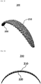
- FIG. 2A is a plan view of a canopy 200 according to a first embodiment of the present invention.
- FIG. 2B is a lateral view of the canopy 200 according to the first embodiment of the present invention.
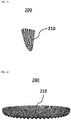
- FIG. 2C is a perspective view of the canopy 200 according to the first embodiment of the present invention.
- FIG. 2D is a front view of the canopy 200 according to the first embodiment of the present invention.
- FIG. 2E is a lateral view of the canopy 200 according to the first embodiment of the present invention.
- FIG. 2F is a plan view of the canopy 200 according to the first embodiment of the present invention.
- the conventional canopy 100 may include an upper wing 110, a lower wing 120 disposed below the upper wing 110 and spaced apart from the upper wing 110, a plurality of air cells 130 each formed independently between the upper wing 110 and the lower wing 120, and an air inlet 140 formed in a leading edge 112 of the upper wing 110 and the lower wing 120 to allow outside air to enter each of the plurality of air cells 130.
- the leading edge 112 of the canopy 100 is formed in the shape of a blunt body, separation bubbles may be formed on the corresponding portion. Due to the separation bubbles, the aerodynamic performance of the conventional canopy 100 may be degraded.
- the canopy 200 may include an upper wing 210, a lower wing 220 disposed below the upper wing 210 and spaced apart from the upper wing 210, a plurality of air cells 230 each formed independently between the upper wing 210 and the lower wing 220, and an air inlet 240 formed in a leading edge 212 of the upper wing 210 and the lower wing 220 to allow outside air to enter each of the plurality of air cells 230.
- the leading edge 212 of the upper wing 210 and the lower wing 220 may be formed of tubercles.
- the term “tubercle” may refer to a nodule, a wave, a protrusion, a sawtooth, or anything equivalent thereto.
- the tubercles of the leading edge 212 may be formed on all or part of each of the upper wing 210 and the lower wing 220.
- the tubercles of the leading edge 212 may be formed in a region excluding both ends of each of the upper wing 210 and the lower wing 220.
- leading edge 212 of the upper wing 210 and the lower wing 220 that corresponds to each of the plurality of air cells 230 may protrude forward or be recessed rearward so that tubercles are formed.
- a lift coefficient may be higher, a stall angle of attack may be increased, and a lift-to-drag ratio may also be increased at the same angle of attack as compared to the conventional canopy 100.
- the overall aerodynamic performance of a paraglider including the canopy 200 according to the present invention may be improved.
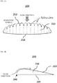
- FIG. 3A is a view illustrating the leading edge 212 and a trailing edge 214 of the canopy 200 according to the first embodiment of the present invention.
- FIGS. 3B to 3F are views showing graphs relating to the aerodynamic performance of the paraglider including the canopy 200 according to the first embodiment of the present invention.
- the leading edge 212 of the canopy 200 may be formed of tubercles.
- a distance between neighboring tubercles may be represented by s
- a distance from an average line 300 to the tubercle may be represented by A
- an average chord length of the canopy 200 (canopy area per span) may be represented by c .
- the canopy area based on the average chord length may be the same for the conventional canopy 100 and the canopy 200 according to the present invention.
- parameters for measuring the aerodynamic performance of a paraglider may be shown as Table 1 below.
- FIG. 4A is a view illustrating a horizontal distance traveled during a fall according to the first embodiment of the present invention.
- FIG. 4B is a view showing a graph of the horizontal distance traveled during the fall according to the first embodiment of the present invention.
- the glide ratio (the horizontal distance traveled divided by the vertical distance traveled) may be calculated for a paraglider including the conventional canopy 100 and a paraglider including the canopy 200 according to the present invention.
- a rate of change of the glide ratio of the paraglider including the canopy 200 according to the present invention may be calculated relative to the glide ratio of the paraglider including the conventional canopy 100.
- the glide ratio of the canopy 200 according to the present invention is changed as shown in Table 2 below relative to the glide ratio of the conventional canopy 100.
- a glide ratio of the conventional canopy 100 that serves as a reference may be 11.42.
- FIG. 5A is a plan view of a conventional canopy 500.
- FIG. 5B is a lateral view of the conventional canopy 500.
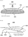
- FIG. 6A is a plan view of a canopy 600 according to a second embodiment of the present invention.
- FIG. 6B is a lateral view of the canopy 600 according to the second embodiment of the present invention.
- the conventional canopy 500 may include an upper wing 510, a lower wing 520 disposed below the upper wing 510 and spaced apart from the upper wing 510, a plurality of air cells 530 each formed independently between the upper wing 510 and the lower wing 520, and an air inlet 540 formed in a leading edge 512 of the upper wing 510 and the lower wing 520 to allow outside air to enter each of the plurality of air cells 530.
- the upper wing 510 of the conventional canopy 500 may expand due to air intake by the air cell 530, and thus flow separation may be formed at an intermediate portion of an upper end of the upper wing 510.
- the canopy 500 expands due to air intake according to an increase in the speed of the paraglider, and thus a slope of a trailing edge 514 of the canopy 500 increases.
- a slope of a trailing edge 514 of the canopy 500 increases.
- the flow separation becomes larger, and drag is increased due to the flow separation.
- the canopy 600 may include an upper wing 610, a lower wing 620 disposed below the upper wing 610 and spaced apart from the upper wing 610, a plurality of air cells 630 each formed independently between the upper wing 610 and the lower wing 620, and an air inlet 640 formed in a leading edge 612 of the upper wing 610 and the lower wing 620 to allow outside air to enter each of the plurality of air cells 630.
- the canopy 600 according to the present invention may further include a cover member 650 having one end coupled to an upper portion of the upper wing 610.
- the other end of the cover member 650 may be separated from the upper wing 610 according to a pressure difference between an upper end part and a lower end part of the cover member 650.
- flow separation at the canopy 600 may be delayed toward a trailing edge 614.
- the canopy 600 according to the present invention may reduce the drag acting on the canopy 600.
- FIG. 7A is a perspective view of a conventional canopy 700.
- FIG. 7B is a plan view of the conventional canopy 700.
- FIG. 7C is a front view of the conventional canopy 700.
- FIG. 8A is a perspective view of a canopy 800 according to a third embodiment of the present invention.
- FIG. 8B is a plan view of the canopy 800 according to the third embodiment of the present invention.
- FIG. 8C is a front view of the canopy 800 according to the third embodiment of the present invention.
- the conventional canopy 700 may include an upper wing 710, a lower wing 720 disposed below the upper wing 710 and spaced apart from the upper wing 710, a plurality of air cells 730, 732, and 734 each formed independently between the upper wing 710 and the lower wing 720, and air inlets 740, 742, and 744 formed in a leading edge 712 of the upper wing 710 and the lower wing 720 to allow outside air to enter each of the plurality of air cells 730, 732, and 734.
- the canopy 800 may include an upper wing 810, a lower wing 820 disposed below the upper wing 810 and spaced apart from the upper wing 810, a plurality of air cells 830, 832, and 834 each formed independently between the upper wing 810 and the lower wing 820, and air inlets 840, 842, and 844 formed in a leading edge 812 of the upper wing 810 and the lower wing 820 to allow outside air to enter each of the plurality of air cells 830, 832, and 834.
- the canopy 800 according to the present invention may further include ridge members 860 and 862 formed to protrude upward from an upper portion of the upper wing 810 based on boundaries 850 and 852 between two adjacent air cells.
- the ridge members 860 and 862 according to the present invention may increase the lift of the canopy 800 and improve the overall aerodynamic performance of the paraglider including the canopy 800. Therefore, as the ridge members 860 and 862 are formed on the boundaries 850 and 852 between the air cells of the canopy 800 according to the present invention, flow separation at a rear end may be delayed to reduce a wake area, and the aerodynamic performance of the canopy 800 may be improved.
- FIGS. 8A to 8C Although only three air cells 840, 842, and 844 and only two ridge members 860 and 862 are illustrated in FIGS. 8A to 8C , the number of air cells and ridge members is not limited thereto.
- FIG. 9 is a perspective view of a conventional canopy 900.
- FIG. 10A is a view illustrating a wingtip structure of a canopy 1000 according to a fourth embodiment of the present invention.
- FIG. 10B is a view illustrating another wingtip structure of the canopy 1000 according to the fourth embodiment of the present invention.
- the conventional canopy 900 may include wingtips 910 and 920 formed at both ends.
- a wingtip vortex that is generated at the wingtips 910 and 920 due to a pressure difference between an upper surface and a lower surface of the canopy 900 may cause a decrease in lift and an increase in drag of the canopy 900, and thus flight stability may be degraded and the wingtips may collapse.
- the conventional canopy 900 may include the configuration of the canopy 100 shown in FIGS. 1A and 1B .
- the canopy 1000 according to the present invention may further include at least one stick-shaped slot winglet 1020 formed at a wingtip 1010 of the canopy 1000.
- the shape of the slot winglet 1020 is not limited to the stick shape.
- the canopy 1000 according to the present invention may further include a ring-shaped spiroid winglet 1030 formed at the wingtip 1010 of the canopy 1000.
- the canopy 1000 according to the present invention may have a higher stall angle of attack and have a higher lift coefficient at the same angle of attack as compared to the conventional canopy 900.
- the canopy 1000 according to the present invention includes a winglet formed at the wingtip 1010, a vortex generated at the wingtip 1010 may be reduced.
- a vortex generated at the wingtip 1010 may be reduced.
- an air flow due to lift (or reaction) may occur in a direction toward an end of a wing.
- the air flow may cancel out a flow of air that tends to flow over an upper side of the wing, and the vortex may be reduced.
- a wingtip vortex may be reduced at the wingtip 1010 of the canopy 1000 and high aerodynamic performance may be achieved.
- tubercles formed on a leading edge can improve a lift coefficient of a canopy, increase a stall angle of attack, and also increase a lift-to-drag ratio.
- the drag acting on the canopy can be reduced.
- higher momentum is generated by a ridge member, making it easier for the flow of air to remain attached to a surface of an upper wing and thus delaying the flow separation.
- a wingtip vortex at the wingtip of the canopy can be reduced and high aerodynamic performance can be achieved.
- One or more embodiments disclosed herein may be separately configured or simultaneously implemented in a canopy according to the present invention.
Landscapes
- Engineering & Computer Science (AREA)
- Aviation & Aerospace Engineering (AREA)
- Toys (AREA)
- Structures Of Non-Positive Displacement Pumps (AREA)
Abstract
Description
- The present invention relates to a paraglider canopy and a paraglider including the same, and more particularly, to a paraglider canopy capable of improving the aerodynamic performance of the canopy and a paraglider including the same.
- Paragliders, which are one gliding means that can generate lift using wind and glide through the air, are mainly used for leisure activities of a large number of people living in a stressful modern society. Due to having an intermediate characteristic between the gliding characteristic of hang gliders and the falling characteristic of parachutes, the paragliders have a high gliding ability and high safety at the same time and are being widely used.
- Generally, the paragliders include a canopy which expands due to the inflow of air and generates lift that allows gliding. In this case, there is an increasing need to reduce separation bubbles and flow separation that occur at the canopy during flight, but research thereon is not sufficient.
- The present invention is directed to providing a paraglider canopy and a paraglider including the same.
- The present invention is also directed to providing a paraglider canopy, which includes a leading edge formed of tubercles, and a paraglider including the same.
- The present invention is also directed to providing a paraglider canopy, which includes a cover member having one end coupled to an upper portion of an upper wing and the other end configured to be separated from the upper wing according to a pressure difference between an upper end part and a lower end part, and a paraglider including the same.
- The present invention is also directed to providing a paraglider canopy, which includes a ridge member formed to protrude upward from an upper portion of an upper wing based on a boundary between two adjacent air cells, and a paraglider including the same.
- The present invention is also directed to providing a paraglider canopy, which includes a slot winglet or spiroid winglet formed at a wingtip of the canopy, and a paraglider including the same.
- The objectives of the present invention are not limited to those mentioned above, and other unmentioned objectives should be clearly understood from the description below.
- A canopy of a paraglider according to an embodiment of the present invention includes: an upper wing; a lower wing disposed below the upper wing and spaced apart from the upper wing; a plurality of air cells each formed independently between the upper wing and the lower wing; and an air inlet formed in a leading edge of the upper wing and the lower wing to allow outside air to enter each of the plurality of air cells, wherein the leading edge of the upper wing and the lower wing may be formed of tubercles.
- The leading edge of the upper wing and the lower wing that corresponds to each of the plurality of air cells may protrude forward or be recessed rearward.
- The canopy may further include a cover member having one end coupled to an upper portion of the upper wing, wherein the other end of the cover member may be separated from the upper wing according to a pressure difference between an upper end part and a lower end part of the cover member.
- The canopy may further include a ridge member formed to protrude upward from the upper portion of the upper wing based on a boundary between two adjacent air cells.
- The canopy may further include at least one stick-shaped slot winglet formed at a wingtip of the canopy.
- The canopy may further include a ring-shaped spiroid winglet formed at a wingtip of the canopy.
- The tubercles of the leading edge are formed on all or part of each of the upper wing and the lower wing.
- A paraglider includes a canopy according to any one of
claims 1 to 6. - Details for achieving the above-mentioned objectives will become apparent with reference to the accompanying drawings and embodiments which are described in detail below.
- However, the present invention is not limited to the embodiments disclosed herein and may be implemented in various different forms. The embodiments are provided to make the disclosure of the present invention complete and to completely inform those of ordinary skill in the art to which the present invention pertains (hereinafter, referred to as "those of ordinary skill in the art") of the scope of the invention.
- The above and other objects, features and advantages of the present invention will become more apparent to those of ordinary skill in the art by describing exemplary embodiments thereof in detail with reference to the accompanying drawings, in which:
-
FIG. 1A is a plan view of a conventional canopy; -
FIG. 1B is a lateral view of the conventional canopy; -
FIG. 2A is a plan view of a canopy according to a first embodiment of the present invention; -
FIG. 2B is a lateral view of the canopy according to the first embodiment of the present invention; -
FIG. 2C is a perspective view of the canopy according to the first embodiment of the present invention; -
FIG. 2D is a front view of the canopy according to the first embodiment of the present invention; -
FIG. 2E is a lateral view of the canopy according to the first embodiment of the present invention; -
FIG. 2F is a plan view of the canopy according to the first embodiment of the present invention; -
FIG. 3A is a view illustrating a leading edge and a trailing edge of the canopy according to the first embodiment of the present invention; -
FIGS. 3B to 3F are views showing graphs relating to the aerodynamic performance of a paraglider including the canopy according to the first embodiment of the present invention; -
FIG. 4A is a view illustrating a horizontal distance traveled during a fall according to the first embodiment of the present invention; -
FIG. 4B is a view showing a graph of the horizontal distance traveled during the fall according to the first embodiment of the present invention; -
FIG. 5A is a plan view of a conventional canopy; -
FIG. 5B is a lateral view of the conventional canopy; -
FIG. 6A is a plan view of a canopy according to a second embodiment of the present invention; -
FIG. 6B is a lateral view of the canopy according to the second embodiment of the present invention; -
FIG. 7A is a perspective view of a conventional canopy; -
FIG. 7B is a plan view of the conventional canopy; -
FIG. 7C is a front view of the conventional canopy; -
FIG. 8A is a perspective view of a canopy according to a third embodiment of the present invention; -
FIG. 8B is a plan view of the canopy according to the third embodiment of the present invention; -
FIG. 8C is a front view of the canopy according to the third embodiment of the present invention; -
FIG. 9 is a perspective view of a conventional canopy; -
FIG. 10A is a view illustrating a wingtip structure of a canopy according to a fourth embodiment of the present invention; and -
FIG. 10B is a view illustrating another wingtip structure of the canopy according to the fourth embodiment of the present invention. - Various modifications may be applied to the present invention, and the present invention may have various embodiments. Specific embodiments illustrated in the drawings will be described in detail below.
- Various features of the invention disclosed in the claims below may be better understood from the drawings and the detailed description herein. Devices, methods, methods of manufacture, and various embodiments disclosed herein are provided for illustrative purposes. Structures and functional features disclosed herein are intended to allow those of ordinary skill in the art to practice various embodiments in detail and are not intended to limit the scope of the invention. Terms and sentences disclosed herein are intended to make it easier to understand various features of the invention disclosed herein and are not intended to limit the scope of the invention.
- In describing the present invention, when it is deemed that detailed description of a known related art may unnecessarily obscure the gist of the present invention, the detailed description thereof will be omitted.
- Hereinafter, a paraglider canopy and a paraglider including the same according to an embodiment of the present invention will be described.
-
FIG. 1A is a plan view of aconventional canopy 100.FIG. 1B is a lateral view of theconventional canopy 100.FIG. 2A is a plan view of acanopy 200 according to a first embodiment of the present invention.FIG. 2B is a lateral view of thecanopy 200 according to the first embodiment of the present invention.FIG. 2C is a perspective view of thecanopy 200 according to the first embodiment of the present invention.FIG. 2D is a front view of thecanopy 200 according to the first embodiment of the present invention.FIG. 2E is a lateral view of thecanopy 200 according to the first embodiment of the present invention.FIG. 2F is a plan view of thecanopy 200 according to the first embodiment of the present invention. - Referring to
FIGS. 1A and 1B , theconventional canopy 100 may include anupper wing 110, alower wing 120 disposed below theupper wing 110 and spaced apart from theupper wing 110, a plurality ofair cells 130 each formed independently between theupper wing 110 and thelower wing 120, and anair inlet 140 formed in aleading edge 112 of theupper wing 110 and thelower wing 120 to allow outside air to enter each of the plurality ofair cells 130. - That is, in the case of the
conventional canopy 100, since theleading edge 112 of thecanopy 100 is formed in the shape of a blunt body, separation bubbles may be formed on the corresponding portion. Due to the separation bubbles, the aerodynamic performance of theconventional canopy 100 may be degraded. - Referring to
FIGS. 2A to 2F , thecanopy 200 according to the present invention may include anupper wing 210, alower wing 220 disposed below theupper wing 210 and spaced apart from theupper wing 210, a plurality ofair cells 230 each formed independently between theupper wing 210 and thelower wing 220, and anair inlet 240 formed in aleading edge 212 of theupper wing 210 and thelower wing 220 to allow outside air to enter each of the plurality ofair cells 230. - In this case, the
leading edge 212 of theupper wing 210 and thelower wing 220 according to the present invention may be formed of tubercles. Here, the term "tubercle" may refer to a nodule, a wave, a protrusion, a sawtooth, or anything equivalent thereto. - In one embodiment, the tubercles of the
leading edge 212 may be formed on all or part of each of theupper wing 210 and thelower wing 220. For example, the tubercles of theleading edge 212 may be formed in a region excluding both ends of each of theupper wing 210 and thelower wing 220. - In one embodiment according to the present invention, the
leading edge 212 of theupper wing 210 and thelower wing 220 that corresponds to each of the plurality ofair cells 230 may protrude forward or be recessed rearward so that tubercles are formed. - In one embodiment, in the case of the
canopy 200 having the leading edge formed of tubercles, a lift coefficient may be higher, a stall angle of attack may be increased, and a lift-to-drag ratio may also be increased at the same angle of attack as compared to theconventional canopy 100. - That is, in the case of the
canopy 200 according to the present invention, since the formation of separation bubbles is delayed by a vortex which is generated due to the tubercles of the leading edge of thecanopy 200, and thus an increase of lift and decrease of drag are achieved, the overall aerodynamic performance of a paraglider including thecanopy 200 according to the present invention may be improved. -
FIG. 3A is a view illustrating theleading edge 212 and a trailingedge 214 of thecanopy 200 according to the first embodiment of the present invention.FIGS. 3B to 3F are views showing graphs relating to the aerodynamic performance of the paraglider including thecanopy 200 according to the first embodiment of the present invention. - Referring to
FIG. 3A , theleading edge 212 of thecanopy 200 according to the present invention may be formed of tubercles. In this case, in the plurality of tubercles, a distance between neighboring tubercles may be represented by s, a distance from anaverage line 300 to the tubercle may be represented by A, and an average chord length of the canopy 200 (canopy area per span) may be represented byc . - In this case, the canopy area based on the average chord length may be the same for the
conventional canopy 100 and thecanopy 200 according to the present invention. - In one embodiment, parameters for measuring the aerodynamic performance of a paraglider may be shown as Table 1 below.

- Here, referring to
FIGS. 3B to 3F , when lift-to-drag ratios according to the s/c values are compared for various A/c values, when an angle of attack (AoA) of an actual paraglider is in a range of 0° to 8°, it can be seen that, in an experimental result in the corresponding range, thecanopy 200 having the tubercles formed according to the present invention has a higher lift-to-drag ratio as compared to the conventional canopy 100 (base). -
FIG. 4A is a view illustrating a horizontal distance traveled during a fall according to the first embodiment of the present invention.FIG. 4B is a view showing a graph of the horizontal distance traveled during the fall according to the first embodiment of the present invention. - Referring to
FIG. 4A , when an angle of attack (AoA) of an actual paraglider is in a range of 0° to 8°, the glide ratio (the horizontal distance traveled divided by the vertical distance traveled) may be calculated for a paraglider including theconventional canopy 100 and a paraglider including thecanopy 200 according to the present invention. - Then, a rate of change of the glide ratio of the paraglider including the
canopy 200 according to the present invention may be calculated relative to the glide ratio of the paraglider including theconventional canopy 100. - In one embodiment, referring to
FIG. 4B , in a case in which 1°<AoA<8°, the glide ratio of thecanopy 200 according to the present invention is changed as shown in Table 2 below relative to the glide ratio of theconventional canopy 100. In this case, for example, a glide ratio of theconventional canopy 100 that serves as a reference may be 11.42.
- In this case, referring to Table 2 above, in a case in which 1°<AoA<8°, it can be seen that, when the A/c value is 0.015 and the s/
c value is 0.57, the glide ratio of thecanopy 200 according to the present invention is increased by 7.934% as compared to the glide ratio of theconventional canopy 100. -
FIG. 5A is a plan view of aconventional canopy 500.FIG. 5B is a lateral view of theconventional canopy 500.FIG. 6A is a plan view of acanopy 600 according to a second embodiment of the present invention.FIG. 6B is a lateral view of thecanopy 600 according to the second embodiment of the present invention. - Referring to
FIGS. 5A and 5B , theconventional canopy 500 may include anupper wing 510, alower wing 520 disposed below theupper wing 510 and spaced apart from theupper wing 510, a plurality ofair cells 530 each formed independently between theupper wing 510 and thelower wing 520, and anair inlet 540 formed in aleading edge 512 of theupper wing 510 and thelower wing 520 to allow outside air to enter each of the plurality ofair cells 530. - In this case, the
upper wing 510 of theconventional canopy 500 may expand due to air intake by theair cell 530, and thus flow separation may be formed at an intermediate portion of an upper end of theupper wing 510. - In the case of the
conventional canopy 500, thecanopy 500 expands due to air intake according to an increase in the speed of the paraglider, and thus a slope of a trailingedge 514 of thecanopy 500 increases. Here, as an angle of inclination of the trailingedge 514 of theupper wing 510 increases, the flow separation becomes larger, and drag is increased due to the flow separation. - On the other hand, referring to
FIGS. 6A and 6B , thecanopy 600 according to the present invention may include anupper wing 610, alower wing 620 disposed below theupper wing 610 and spaced apart from theupper wing 610, a plurality ofair cells 630 each formed independently between theupper wing 610 and thelower wing 620, and anair inlet 640 formed in aleading edge 612 of theupper wing 610 and thelower wing 620 to allow outside air to enter each of the plurality ofair cells 630. - In this case, the
canopy 600 according to the present invention may further include acover member 650 having one end coupled to an upper portion of theupper wing 610. Here, the other end of thecover member 650 may be separated from theupper wing 610 according to a pressure difference between an upper end part and a lower end part of thecover member 650. Thus, flow separation at thecanopy 600 may be delayed toward a trailingedge 614. - That is, by using the
cover member 650 to delay flow separation, thecanopy 600 according to the present invention may reduce the drag acting on thecanopy 600. -
FIG. 7A is a perspective view of aconventional canopy 700.FIG. 7B is a plan view of theconventional canopy 700.FIG. 7C is a front view of theconventional canopy 700.FIG. 8A is a perspective view of acanopy 800 according to a third embodiment of the present invention.FIG. 8B is a plan view of thecanopy 800 according to the third embodiment of the present invention.FIG. 8C is a front view of thecanopy 800 according to the third embodiment of the present invention. - Referring to
FIGS. 7A to 7C , theconventional canopy 700 may include anupper wing 710, alower wing 720 disposed below theupper wing 710 and spaced apart from theupper wing 710, a plurality ofair cells upper wing 710 and thelower wing 720, andair inlets leading edge 712 of theupper wing 710 and thelower wing 720 to allow outside air to enter each of the plurality ofair cells - In this case, as an angle of attack of the
conventional canopy 700 increases, flow separation occurs and a wake area is formed. The wake area and flow separation cause a lift-to-drag ratio of the canopy to be decreased. - On the other hand, referring to
FIGS. 8A to 8C , thecanopy 800 according to the present invention may include anupper wing 810, alower wing 820 disposed below theupper wing 810 and spaced apart from theupper wing 810, a plurality ofair cells upper wing 810 and thelower wing 820, andair inlets leading edge 812 of theupper wing 810 and thelower wing 820 to allow outside air to enter each of the plurality ofair cells - In one embodiment, the
canopy 800 according to the present invention may further includeridge members upper wing 810 based onboundaries - In this case, in a case in which the
ridge members upper wing 810, higher momentum is generated due to a vortex generated by theridge members upper wing 810 and thus delaying the flow separation. - That is, the
ridge members canopy 800 and improve the overall aerodynamic performance of the paraglider including thecanopy 800. Therefore, as theridge members boundaries canopy 800 according to the present invention, flow separation at a rear end may be delayed to reduce a wake area, and the aerodynamic performance of thecanopy 800 may be improved. - In one embodiment, although only three
air cells ridge members FIGS. 8A to 8C , the number of air cells and ridge members is not limited thereto. -
FIG. 9 is a perspective view of aconventional canopy 900.FIG. 10A is a view illustrating a wingtip structure of acanopy 1000 according to a fourth embodiment of the present invention.FIG. 10B is a view illustrating another wingtip structure of thecanopy 1000 according to the fourth embodiment of the present invention. - Referring to
FIG. 9 , theconventional canopy 900 may includewingtips wingtips canopy 900 may cause a decrease in lift and an increase in drag of thecanopy 900, and thus flight stability may be degraded and the wingtips may collapse. - In one embodiment, the
conventional canopy 900 may include the configuration of thecanopy 100 shown inFIGS. 1A and 1B . - On the other hand, referring to
FIG. 10A , thecanopy 1000 according to the present invention may further include at least one stick-shapedslot winglet 1020 formed at awingtip 1010 of thecanopy 1000. In this case, the shape of theslot winglet 1020 is not limited to the stick shape. - Also, referring to
FIG. 10B , thecanopy 1000 according to the present invention may further include a ring-shapedspiroid winglet 1030 formed at thewingtip 1010 of thecanopy 1000. - In this case, due to the inclusion of the
spiroid winglet 1030, thecanopy 1000 according to the present invention may have a higher stall angle of attack and have a higher lift coefficient at the same angle of attack as compared to theconventional canopy 900. - Also, although drag increases after the stall angle of attack in the case of the
conventional canopy 900, the extent to which drag increases may be alleviated by thespiroid winglet 1030, and the lift-to-drag ratio according to the angle of attack may also be higher as a whole. - That is, since the
canopy 1000 according to the present invention includes a winglet formed at thewingtip 1010, a vortex generated at thewingtip 1010 may be reduced. For example, since thewingtip 1010 is slightly lifted upward due to the winglet, an air flow due to lift (or reaction) may occur in a direction toward an end of a wing. Thus, the air flow may cancel out a flow of air that tends to flow over an upper side of the wing, and the vortex may be reduced. - Therefore, by adding the
slot winglet 1020 orspiroid winglet 1030 to thewingtip 1010 of thecanopy 1000 according to the present invention, a wingtip vortex may be reduced at thewingtip 1010 of thecanopy 1000 and high aerodynamic performance may be achieved. - According to an embodiment of the present invention, tubercles formed on a leading edge can improve a lift coefficient of a canopy, increase a stall angle of attack, and also increase a lift-to-drag ratio.
- In addition, according to an embodiment of the present invention, by using a cover member to delay flow separation, the drag acting on the canopy can be reduced.
- In addition, according to an embodiment of the present invention, higher momentum is generated by a ridge member, making it easier for the flow of air to remain attached to a surface of an upper wing and thus delaying the flow separation.
- In addition, according to an embodiment of the present invention, by adding a slot winglet or spiroid winglet to a wingtip of the canopy, a wingtip vortex at the wingtip of the canopy can be reduced and high aerodynamic performance can be achieved.
- The advantageous effects of the present invention are not limited to those described above, and other potential effects expected from the technical features of the present invention should be clearly understood from the description above.
- One or more embodiments disclosed herein may be separately configured or simultaneously implemented in a canopy according to the present invention.
- The above description is merely illustrative of the technical idea of the present invention, and those of ordinary skill in the art may make various changes and modifications without departing from the essential characteristics of the present invention.
- Therefore, the embodiments disclosed herein are for describing, instead of limiting, the technical idea of the present invention, and the scope of the present invention is not limited by the embodiments.
- The scope of the present invention should be interpreted from the claims below, and all technical ideas within the scope equivalent thereto should be understood as falling within the scope of the present invention.
Claims (8)
- A canopy of a paraglider, the canopy comprising:an upper wing;a lower wing disposed below the upper wing and spaced apart from the upper wing;a plurality of air cells each formed independently between the upper wing and the lower wing; andan air inlet formed in a leading edge of the upper wing and the lower wing to allow outside air to enter each of the plurality of air cells,wherein the leading edge of the upper wing and the lower wing is formed of tubercles.
- The canopy of claim 1, wherein the leading edge of the upper wing and the lower wing that corresponds to each of the plurality of air cells protrudes forward or is recessed rearward.
- The canopy of claim 1, further comprising a cover member having one end coupled to an upper portion of the upper wing,
wherein the other end of the cover member is separated from the upper wing according to a pressure difference between an upper end part and a lower end part of the cover member. - The canopy of claim 1, further comprising a ridge member formed to protrude upward from an upper portion of the upper wing based on a boundary between two adjacent air cells.
- The canopy of claim 1, further comprising at least one stick-shaped slot winglet formed at a wingtip of the canopy.
- The canopy of claim 1, further comprising a ring-shaped spiroid winglet formed at a wingtip of the canopy.
- The canopy of claim 1, wherein the tubercles of the leading edge are formed on all or part of each of the upper wing and the lower wing.
- A paraglider comprising the canopy of any one of claims 1 to 7.
Priority Applications (1)
| Application Number | Priority Date | Filing Date | Title |
|---|---|---|---|
| EP22204174.1A EP4144640A1 (en) | 2020-04-14 | 2020-11-19 | Paraglider canopy and paraglider including the same |
Applications Claiming Priority (1)
| Application Number | Priority Date | Filing Date | Title |
|---|---|---|---|
| KR1020200045494A KR102359176B1 (en) | 2020-04-14 | 2020-04-14 | Paraglider canopy and paraglider with the same |
Related Child Applications (1)
| Application Number | Title | Priority Date | Filing Date |
|---|---|---|---|
| EP22204174.1A Division EP4144640A1 (en) | 2020-04-14 | 2020-11-19 | Paraglider canopy and paraglider including the same |
Publications (1)
| Publication Number | Publication Date |
|---|---|
| EP3895985A1 true EP3895985A1 (en) | 2021-10-20 |
Family
ID=73497561
Family Applications (2)
| Application Number | Title | Priority Date | Filing Date |
|---|---|---|---|
| EP20208575.9A Withdrawn EP3895985A1 (en) | 2020-04-14 | 2020-11-19 | Paraglider canopy and paraglider including the same |
| EP22204174.1A Pending EP4144640A1 (en) | 2020-04-14 | 2020-11-19 | Paraglider canopy and paraglider including the same |
Family Applications After (1)
| Application Number | Title | Priority Date | Filing Date |
|---|---|---|---|
| EP22204174.1A Pending EP4144640A1 (en) | 2020-04-14 | 2020-11-19 | Paraglider canopy and paraglider including the same |
Country Status (2)
| Country | Link |
|---|---|
| EP (2) | EP3895985A1 (en) |
| KR (1) | KR102359176B1 (en) |
Families Citing this family (1)
| Publication number | Priority date | Publication date | Assignee | Title |
|---|---|---|---|---|
| KR102432889B1 (en) * | 2020-12-22 | 2022-08-18 | 주식회사 진글라이더 | Paraglider canopy and paraglider with the same |
Citations (6)
| Publication number | Priority date | Publication date | Assignee | Title |
|---|---|---|---|---|
| DE8807211U1 (en) * | 1988-06-02 | 1988-09-22 | Leibe, Gernot, Dipl.-Ing., 8000 München | Paraglider with partially closed stiffened profile nose and V-shaped inlet openings |
| FR2636597A1 (en) * | 1988-09-22 | 1990-03-23 | Vermot Gh Jacques | Device for aerodynamic stabilisation and for regulation of the outflow of air for a parapent wing and a parachute wing which is inflatable by the relative wind |
| DE9015289U1 (en) * | 1990-11-07 | 1991-01-31 | Bauer, Karl, Dipl.-Ing., 8176 Schaftlach | Paragliding |
| JPH0490494U (en) * | 1990-09-20 | 1992-08-06 | ||
| DE29721797U1 (en) * | 1997-12-10 | 1998-07-23 | Beck, Volker, 79211 Denzlingen | Jump parachute |
| WO2014016901A1 (en) * | 2012-07-24 | 2014-01-30 | TONODUKA Hideaki | Double-layered flexible wing |
Family Cites Families (2)
| Publication number | Priority date | Publication date | Assignee | Title |
|---|---|---|---|---|
| KR101276311B1 (en) * | 2011-11-25 | 2013-06-18 | 주식회사 진글라이더 | Paraglider with protruding trailing edge. |
| CN104022188B (en) | 2014-06-19 | 2016-05-11 | 常州天合光能有限公司 | Solar battery local doping method |
-
2020
- 2020-04-14 KR KR1020200045494A patent/KR102359176B1/en active Active
- 2020-11-19 EP EP20208575.9A patent/EP3895985A1/en not_active Withdrawn
- 2020-11-19 EP EP22204174.1A patent/EP4144640A1/en active Pending
Patent Citations (6)
| Publication number | Priority date | Publication date | Assignee | Title |
|---|---|---|---|---|
| DE8807211U1 (en) * | 1988-06-02 | 1988-09-22 | Leibe, Gernot, Dipl.-Ing., 8000 München | Paraglider with partially closed stiffened profile nose and V-shaped inlet openings |
| FR2636597A1 (en) * | 1988-09-22 | 1990-03-23 | Vermot Gh Jacques | Device for aerodynamic stabilisation and for regulation of the outflow of air for a parapent wing and a parachute wing which is inflatable by the relative wind |
| JPH0490494U (en) * | 1990-09-20 | 1992-08-06 | ||
| DE9015289U1 (en) * | 1990-11-07 | 1991-01-31 | Bauer, Karl, Dipl.-Ing., 8176 Schaftlach | Paragliding |
| DE29721797U1 (en) * | 1997-12-10 | 1998-07-23 | Beck, Volker, 79211 Denzlingen | Jump parachute |
| WO2014016901A1 (en) * | 2012-07-24 | 2014-01-30 | TONODUKA Hideaki | Double-layered flexible wing |
Also Published As
| Publication number | Publication date |
|---|---|
| KR20210127517A (en) | 2021-10-22 |
| EP4144640A1 (en) | 2023-03-08 |
| KR102359176B1 (en) | 2022-02-08 |
Similar Documents
| Publication | Publication Date | Title |
|---|---|---|
| US11498678B2 (en) | Blended wing body aircraft | |
| US6578798B1 (en) | Airlifting surface division | |
| US20230202655A1 (en) | Blended wing body aircraft | |
| US20170073062A1 (en) | Variable Geometry Wingtip | |
| CN101547829A (en) | Highly efficient supersonic laminar flow wing | |
| CN103231795A (en) | Corporate aircraft engine upper placement and front swept wing duck type layout | |
| US20200023945A1 (en) | Aerodynamic surface of an aircraft | |
| EP4144640A1 (en) | Paraglider canopy and paraglider including the same | |
| CN103419923A (en) | Thrust gain device with high-speed wall attached air flow | |
| US8382040B2 (en) | Hamilton H.N2 laminar flow diskette wing | |
| US20120032033A1 (en) | Wing piercing airplane | |
| RU2144885C1 (en) | Maneuverable trainer multi-mission aircraft "yak- 130" | |
| KR102432889B1 (en) | Paraglider canopy and paraglider with the same | |
| US6957792B2 (en) | Lifting arrangement for aircraft fuselages | |
| JP3192450U (en) | Model airplane | |
| CN205366050U (en) | Fixed -wing unmanned aerial vehicle | |
| US20050116087A1 (en) | Aircraft converts drag to lift | |
| KR20180000005A (en) | Paraglider | |
| US4895323A (en) | Rag control for powered lift aircraft | |
| CN113581459B (en) | High lift assembly for composite wing aircraft and composite wing aircraft | |
| JP2017081260A (en) | Wing tip structure for suppressing lift loss due to vortex drag generated at side of wing | |
| US12515783B2 (en) | Aircraft tail surface | |
| RU194250U1 (en) | Small Elongation Wing for Subsonic Aircraft | |
| CN203740117U (en) | Canard wing strake system of high-mobility aircraft | |
| Xie et al. | The optimization study on the mitigation strategy of hinge moment of aircraft with multi-control surfaces |
Legal Events
| Date | Code | Title | Description |
|---|---|---|---|
| PUAI | Public reference made under article 153(3) epc to a published international application that has entered the european phase |
Free format text: ORIGINAL CODE: 0009012 |
|
| STAA | Information on the status of an ep patent application or granted ep patent |
Free format text: STATUS: THE APPLICATION HAS BEEN PUBLISHED |
|
| AK | Designated contracting states |
Kind code of ref document: A1 Designated state(s): AL AT BE BG CH CY CZ DE DK EE ES FI FR GB GR HR HU IE IS IT LI LT LU LV MC MK MT NL NO PL PT RO RS SE SI SK SM TR |
|
| B565 | Issuance of search results under rule 164(2) epc |
Effective date: 20210426 |
|
| STAA | Information on the status of an ep patent application or granted ep patent |
Free format text: STATUS: REQUEST FOR EXAMINATION WAS MADE |
|
| 17P | Request for examination filed |
Effective date: 20220420 |
|
| RBV | Designated contracting states (corrected) |
Designated state(s): AL AT BE BG CH CY CZ DE DK EE ES FI FR GB GR HR HU IE IS IT LI LT LU LV MC MK MT NL NO PL PT RO RS SE SI SK SM TR |
|
| STAA | Information on the status of an ep patent application or granted ep patent |
Free format text: STATUS: EXAMINATION IS IN PROGRESS |
|
| 17Q | First examination report despatched |
Effective date: 20230504 |
|
| GRAP | Despatch of communication of intention to grant a patent |
Free format text: ORIGINAL CODE: EPIDOSNIGR1 |
|
| STAA | Information on the status of an ep patent application or granted ep patent |
Free format text: STATUS: GRANT OF PATENT IS INTENDED |
|
| INTG | Intention to grant announced |
Effective date: 20250324 |
|
| STAA | Information on the status of an ep patent application or granted ep patent |
Free format text: STATUS: THE APPLICATION IS DEEMED TO BE WITHDRAWN |
|
| 18D | Application deemed to be withdrawn |
Effective date: 20250725 |
|
| 18RA | Request filed for re-establishment of rights before grant |
Effective date: 20251205 |
|
| GRAS | Grant fee paid |
Free format text: ORIGINAL CODE: EPIDOSNIGR3 |
|
| STAA | Information on the status of an ep patent application or granted ep patent |
Free format text: STATUS: GRANT OF PATENT IS INTENDED |