EP3895801B1 - Valve system for driving fluid and method for using the same - Google Patents
Valve system for driving fluid and method for using the same Download PDFInfo
- Publication number
- EP3895801B1 EP3895801B1 EP21151493.0A EP21151493A EP3895801B1 EP 3895801 B1 EP3895801 B1 EP 3895801B1 EP 21151493 A EP21151493 A EP 21151493A EP 3895801 B1 EP3895801 B1 EP 3895801B1
- Authority
- EP
- European Patent Office
- Prior art keywords
- fluid
- rotation center
- pipeline
- driving
- valve system
- Prior art date
- Legal status (The legal status is an assumption and is not a legal conclusion. Google has not performed a legal analysis and makes no representation as to the accuracy of the status listed.)
- Active
Links
Images



Classifications
-
- B—PERFORMING OPERATIONS; TRANSPORTING
- B01—PHYSICAL OR CHEMICAL PROCESSES OR APPARATUS IN GENERAL
- B01L—CHEMICAL OR PHYSICAL LABORATORY APPARATUS FOR GENERAL USE
- B01L3/00—Containers or dishes for laboratory use, e.g. laboratory glassware; Droppers
- B01L3/50—Containers for the purpose of retaining a material to be analysed, e.g. test tubes
- B01L3/502—Containers for the purpose of retaining a material to be analysed, e.g. test tubes with fluid transport, e.g. in multi-compartment structures
- B01L3/5027—Containers for the purpose of retaining a material to be analysed, e.g. test tubes with fluid transport, e.g. in multi-compartment structures by integrated microfluidic structures, i.e. dimensions of channels and chambers are such that surface tension forces are important, e.g. lab-on-a-chip
- B01L3/50273—Containers for the purpose of retaining a material to be analysed, e.g. test tubes with fluid transport, e.g. in multi-compartment structures by integrated microfluidic structures, i.e. dimensions of channels and chambers are such that surface tension forces are important, e.g. lab-on-a-chip characterised by the means or forces applied to move the fluids
-
- B—PERFORMING OPERATIONS; TRANSPORTING
- B01—PHYSICAL OR CHEMICAL PROCESSES OR APPARATUS IN GENERAL
- B01L—CHEMICAL OR PHYSICAL LABORATORY APPARATUS FOR GENERAL USE
- B01L3/00—Containers or dishes for laboratory use, e.g. laboratory glassware; Droppers
- B01L3/50—Containers for the purpose of retaining a material to be analysed, e.g. test tubes
- B01L3/502—Containers for the purpose of retaining a material to be analysed, e.g. test tubes with fluid transport, e.g. in multi-compartment structures
- B01L3/5027—Containers for the purpose of retaining a material to be analysed, e.g. test tubes with fluid transport, e.g. in multi-compartment structures by integrated microfluidic structures, i.e. dimensions of channels and chambers are such that surface tension forces are important, e.g. lab-on-a-chip
-
- B—PERFORMING OPERATIONS; TRANSPORTING
- B01—PHYSICAL OR CHEMICAL PROCESSES OR APPARATUS IN GENERAL
- B01L—CHEMICAL OR PHYSICAL LABORATORY APPARATUS FOR GENERAL USE
- B01L3/00—Containers or dishes for laboratory use, e.g. laboratory glassware; Droppers
- B01L3/50—Containers for the purpose of retaining a material to be analysed, e.g. test tubes
- B01L3/502—Containers for the purpose of retaining a material to be analysed, e.g. test tubes with fluid transport, e.g. in multi-compartment structures
- B01L3/5027—Containers for the purpose of retaining a material to be analysed, e.g. test tubes with fluid transport, e.g. in multi-compartment structures by integrated microfluidic structures, i.e. dimensions of channels and chambers are such that surface tension forces are important, e.g. lab-on-a-chip
- B01L3/502738—Containers for the purpose of retaining a material to be analysed, e.g. test tubes with fluid transport, e.g. in multi-compartment structures by integrated microfluidic structures, i.e. dimensions of channels and chambers are such that surface tension forces are important, e.g. lab-on-a-chip characterised by integrated valves
-
- C—CHEMISTRY; METALLURGY
- C12—BIOCHEMISTRY; BEER; SPIRITS; WINE; VINEGAR; MICROBIOLOGY; ENZYMOLOGY; MUTATION OR GENETIC ENGINEERING
- C12M—APPARATUS FOR ENZYMOLOGY OR MICROBIOLOGY; APPARATUS FOR CULTURING MICROORGANISMS FOR PRODUCING BIOMASS, FOR GROWING CELLS OR FOR OBTAINING FERMENTATION OR METABOLIC PRODUCTS, i.e. BIOREACTORS OR FERMENTERS
- C12M1/00—Apparatus for enzymology or microbiology
-
- C—CHEMISTRY; METALLURGY
- C12—BIOCHEMISTRY; BEER; SPIRITS; WINE; VINEGAR; MICROBIOLOGY; ENZYMOLOGY; MUTATION OR GENETIC ENGINEERING
- C12M—APPARATUS FOR ENZYMOLOGY OR MICROBIOLOGY; APPARATUS FOR CULTURING MICROORGANISMS FOR PRODUCING BIOMASS, FOR GROWING CELLS OR FOR OBTAINING FERMENTATION OR METABOLIC PRODUCTS, i.e. BIOREACTORS OR FERMENTERS
- C12M1/00—Apparatus for enzymology or microbiology
- C12M1/34—Measuring or testing with condition measuring or sensing means, e.g. colony counters
-
- C—CHEMISTRY; METALLURGY
- C12—BIOCHEMISTRY; BEER; SPIRITS; WINE; VINEGAR; MICROBIOLOGY; ENZYMOLOGY; MUTATION OR GENETIC ENGINEERING
- C12M—APPARATUS FOR ENZYMOLOGY OR MICROBIOLOGY; APPARATUS FOR CULTURING MICROORGANISMS FOR PRODUCING BIOMASS, FOR GROWING CELLS OR FOR OBTAINING FERMENTATION OR METABOLIC PRODUCTS, i.e. BIOREACTORS OR FERMENTERS
- C12M1/00—Apparatus for enzymology or microbiology
- C12M1/36—Apparatus for enzymology or microbiology including condition or time responsive control, e.g. automatically controlled fermentors
- C12M1/38—Temperature-responsive control
-
- F—MECHANICAL ENGINEERING; LIGHTING; HEATING; WEAPONS; BLASTING
- F16—ENGINEERING ELEMENTS AND UNITS; GENERAL MEASURES FOR PRODUCING AND MAINTAINING EFFECTIVE FUNCTIONING OF MACHINES OR INSTALLATIONS; THERMAL INSULATION IN GENERAL
- F16K—VALVES; TAPS; COCKS; ACTUATING-FLOATS; DEVICES FOR VENTING OR AERATING
- F16K31/00—Actuating devices; Operating means; Releasing devices
- F16K31/12—Actuating devices; Operating means; Releasing devices actuated by fluid
-
- B—PERFORMING OPERATIONS; TRANSPORTING
- B01—PHYSICAL OR CHEMICAL PROCESSES OR APPARATUS IN GENERAL
- B01L—CHEMICAL OR PHYSICAL LABORATORY APPARATUS FOR GENERAL USE
- B01L2200/00—Solutions for specific problems relating to chemical or physical laboratory apparatus
- B01L2200/06—Fluid handling related problems
- B01L2200/0621—Control of the sequence of chambers filled or emptied
-
- B—PERFORMING OPERATIONS; TRANSPORTING
- B01—PHYSICAL OR CHEMICAL PROCESSES OR APPARATUS IN GENERAL
- B01L—CHEMICAL OR PHYSICAL LABORATORY APPARATUS FOR GENERAL USE
- B01L2300/00—Additional constructional details
- B01L2300/08—Geometry, shape and general structure
-
- B—PERFORMING OPERATIONS; TRANSPORTING
- B01—PHYSICAL OR CHEMICAL PROCESSES OR APPARATUS IN GENERAL
- B01L—CHEMICAL OR PHYSICAL LABORATORY APPARATUS FOR GENERAL USE
- B01L2300/00—Additional constructional details
- B01L2300/08—Geometry, shape and general structure
- B01L2300/0803—Disc shape
-
- B—PERFORMING OPERATIONS; TRANSPORTING
- B01—PHYSICAL OR CHEMICAL PROCESSES OR APPARATUS IN GENERAL
- B01L—CHEMICAL OR PHYSICAL LABORATORY APPARATUS FOR GENERAL USE
- B01L2300/00—Additional constructional details
- B01L2300/08—Geometry, shape and general structure
- B01L2300/0809—Geometry, shape and general structure rectangular shaped
-
- B—PERFORMING OPERATIONS; TRANSPORTING
- B01—PHYSICAL OR CHEMICAL PROCESSES OR APPARATUS IN GENERAL
- B01L—CHEMICAL OR PHYSICAL LABORATORY APPARATUS FOR GENERAL USE
- B01L2300/00—Additional constructional details
- B01L2300/08—Geometry, shape and general structure
- B01L2300/0809—Geometry, shape and general structure rectangular shaped
- B01L2300/0819—Microarrays; Biochips
-
- B—PERFORMING OPERATIONS; TRANSPORTING
- B01—PHYSICAL OR CHEMICAL PROCESSES OR APPARATUS IN GENERAL
- B01L—CHEMICAL OR PHYSICAL LABORATORY APPARATUS FOR GENERAL USE
- B01L2400/00—Moving or stopping fluids
- B01L2400/04—Moving fluids with specific forces or mechanical means
- B01L2400/0403—Moving fluids with specific forces or mechanical means specific forces
- B01L2400/0406—Moving fluids with specific forces or mechanical means specific forces capillary forces
-
- B—PERFORMING OPERATIONS; TRANSPORTING
- B01—PHYSICAL OR CHEMICAL PROCESSES OR APPARATUS IN GENERAL
- B01L—CHEMICAL OR PHYSICAL LABORATORY APPARATUS FOR GENERAL USE
- B01L2400/00—Moving or stopping fluids
- B01L2400/04—Moving fluids with specific forces or mechanical means
- B01L2400/0403—Moving fluids with specific forces or mechanical means specific forces
- B01L2400/0409—Moving fluids with specific forces or mechanical means specific forces centrifugal forces
-
- B—PERFORMING OPERATIONS; TRANSPORTING
- B01—PHYSICAL OR CHEMICAL PROCESSES OR APPARATUS IN GENERAL
- B01L—CHEMICAL OR PHYSICAL LABORATORY APPARATUS FOR GENERAL USE
- B01L2400/00—Moving or stopping fluids
- B01L2400/06—Valves, specific forms thereof
-
- F—MECHANICAL ENGINEERING; LIGHTING; HEATING; WEAPONS; BLASTING
- F16—ENGINEERING ELEMENTS AND UNITS; GENERAL MEASURES FOR PRODUCING AND MAINTAINING EFFECTIVE FUNCTIONING OF MACHINES OR INSTALLATIONS; THERMAL INSULATION IN GENERAL
- F16K—VALVES; TAPS; COCKS; ACTUATING-FLOATS; DEVICES FOR VENTING OR AERATING
- F16K99/00—Subject matter not provided for in other groups of this subclass
- F16K99/0001—Microvalves
- F16K99/0034—Operating means specially adapted for microvalves
- F16K99/0055—Operating means specially adapted for microvalves actuated by fluids
Definitions
- the present application relates to the technical field of medical instruments, and in particular to a valve system for driving fluid.
- the present application further relates to a method for using the valve system for driving the fluid.
- a driving force of liquid is mainly centrifugal force along the radius direction from an end far away from a rotation center towards the outside.
- the flow of the liquid may be controlled in time sequence by combining with functional structures such as a siphon valve and the like.
- the centrifugal force generated when a chip rotates is used to drive the liquid, which reduces the complexity of a liquid control system and is a microfluidic driving method usually used in a simple microfluidic system.
- the driving force on the liquid has only an approximate direction, that is, along a radius direction from an end close to the rotation center to the end far away from the rotation center.
- an upstream fluid unit 02, a fluid unit far away from a rotation center 03 and a downstream fluid unit 04 are sequentially communicated from a central position 01 towards the outside in the radial direction.
- a gas path passage 05 communicates the upstream fluid unit with the downstream fluid unit, so that the liquid flows outward along the radius direction.
- a microsystem platform is provided for use with a micromanipulation device to manipulate the platform by rotation, thereby utilizing the centripetal force resulting from rotation of the platform to motivate fluid movement through microchannels embedded in the microplatform.
- the microsystem platform is also provided having microfluidics components, resistive heating elements, temperature sensing elements, mixing structures, capillary and sacrificial valves, and methods for using these microsystem platforms for perform biological, enzymatic, immunological and chemical assays.
- An object of the present application is to provide a valve system for driving fluid, so as to facilitate the fluid transfer in a microfluidic chip. And another object of the present application is to provide a method for using the valve system for driving the fluid.
- a valve system for driving fluid is provided according to the present application, which is applied to a microfluidic chip and includes a fluid unit far away from a rotation center, a fluid unit close to the rotation center, a fluid transferring unit and a gas path pipeline for communicating the fluid unit close to the rotation center with the fluid unit far away from the rotation center.
- a rotation radius of a fluid outlet of the fluid unit far away from the rotation center is greater than a rotation radius of a fluid inlet of the fluid unit close to the rotation center.
- the fluid outlet of the fluid unit far away from the rotation center is located at an end, away from the rotation center, of the fluid unit far away from the rotation center, and the fluid inlet of the fluid unit close to the rotation center is located at an end, close to the rotation center, of the fluid unit close to the rotation center.
- the fluid transferring unit is a fluid pipeline.
- a fluid inlet end of the fluid pipeline is connected to the fluid outlet of the fluid unit far away from the rotation center and a fluid outlet end of the fluid pipeline is connected to the fluid inlet of the fluid unit close to the rotation center.
- a micro array structure which facilitates fluid transfer is provided on an inner wall of the fluid unit close to the rotation center and/or an inner wall of the fluid pipeline.
- a suction force of the fluid unit close to the rotation center and a suction force of the fluid pipeline are greater than a suction force of the fluid unit far away from the rotation center, in a centrifugation stop state, liquid in the fluid unit far away from the rotation center is transferred into the fluid unit close to the rotation center via the fluid pipeline under capillary action.
- the number of the fluid unit close to the rotation center is one.
- the fluid unit close to the rotation center is a chamber
- the chamber is a thin chamber with a chamber height from 0.01mm to 2mm or a thick chamber with the chamber height from 2mm to 10mm.
- the micro array structure is circular, elliptic or polygonal.
- a fluid adsorbing structure in block-shaped or layer-shaped is provided in the fluid unit close to the rotation center, and the fluid absorbing structure is not configured to react with the liquid transferred into the fluid unit close to the rotation center.
- the number of the fluid unit close to the rotation center is at least two, and each of the at least two fluid unit close to the rotation centers is independently arranged.
- Multiple fluid pipelines are provided, and each of the multiple fluid pipelines is independently arranged.
- the number of fluid unit close to the rotation centers is equal to the number of fluid pipelines, and each of the fluid unit close to the rotation centers is connected to a respective one of the fluid pipelines.
- the shape of the cross section of the fluid pipeline is rectangular, circular or elliptic, and the cross section of the fluid pipeline has the equivalent diameter from 0.01mm to 2mm.
- one or more valve systems for driving the fluid are arranged in a radial direction and a circumferential direction.
- a rotation center position of the valve system for driving the fluid is located outside a reactor or inside the reactor.
- a method for using the valve system for driving the fluid is applied to the valve system for driving the fluid and includes:
- the surfactant is sodium dodecyl sulfate and/or polyethylene glycol octylphenol ether and/or agarose and/or polysorbate and/or polypeptide.
- the valve system for driving the fluid according to the present application is applied to the microfluidic chip and includes the fluid unit far away from the rotation center, the fluid unit close to the rotation center, the fluid transferring unit and the gas path pipeline for communicating the fluid unit close to the rotation center with the fluid unit far away from the rotation center.
- the rotation radius of the fluid outlet of the fluid unit far away from the rotation center is greater than the rotation radius of the fluid inlet of the fluid unit close to the rotation center.
- the fluid outlet of the fluid unit far away from the rotation center is located at the end of the fluid unit far away from the rotation center away from the rotation center, and the fluid inlet of the fluid unit close to the rotation center is located at the end of the fluid unit close to the rotation center close to the rotation center.
- the fluid transferring unit is the fluid pipeline.
- the fluid inlet end of the fluid pipeline is connected to the fluid outlet of the fluid unit far away from the rotation center and the fluid outlet end of the fluid pipeline is connected to the fluid inlet of the fluid unit close to the rotation center.
- a micro array structure which facilitates fluid transfer is provided on an inner wall of the fluid unit close to the rotation center and/or an inner wall of the fluid pipeline.
- the suction force of the fluid unit close to the rotation center and the suction force of the fluid pipeline are greater than that of the fluid unit far away from the rotation center.
- the liquid in the fluid unit far away from the rotation center flows into the fluid unit close to the rotation center via the fluid pipeline, and the liquid flows into a downstream unit of the fluid unit close to the rotation center under the action of centrifugal force after flowing into the fluid unit close to the rotation center.
- the liquid in the fluid unit far away from the rotation center which is far from the rotation center is transferred to the fluid unit close to the rotation center which is close to the rotation center through the fluid pipeline, so as to realize liquid backflow to the rotation center.
- the suction force of the fluid unit close to the rotation center and the suction force of the fluid pipeline are greater than the suction force of the fluid unit far away from the rotation center, the fluid transfer may be realized under capillary action without any external force, and the operation is simple, thus facilitating the fluid transfer in the microfluidic chip.
- a core of the present application is to provide a valve system for driving the fluid, so as to reduce the size of a microfluidic chip in the direction of a rotation radius.
- another core of the present application is to provide a method for using the valve system for driving the fluid.
- the valve system for driving the fluid is applied to the microfluidic chip and includes a fluid unit far away from the rotation center 3, a fluid unit close to the rotation center 7, a fluid transferring unit and a gas path pipeline 5 for communicating the fluid unit close to the rotation center 7 with the fluid unit far away from the rotation center 3.
- the fluid transferring unit is configured to drive fluid in the fluid unit far away from the rotation center 3 into the fluid unit close to the rotation center 7.
- the fluid unit close to the rotation center 7 is located at a downstream of the fluid transferring unit, and the fluid transferring unit is a fluid pipeline 6, as shown in Figures 2 to 8 .
- the rotation radius of a fluid outlet of the fluid unit far away from the rotation center 3 is greater than the rotation radius of a fluid inlet of the fluid unit close to the rotation center 7.
- the rotation radius of the fluid outlet of the fluid unit far away from the rotation center 3 is greater than the rotation radius of the fluid outlet of the fluid unit close to the rotation center 7.
- an inlet passage far away from the rotation center 8 is provided outside the fluid inlet of the fluid unit far away from the rotation center 3 to be connected with an external device for inputting the liquid.
- an outlet passage close to the rotation center 9 is provided outside the fluid outlet of the fluid unit close to the rotation center 7 to output the liquid.
- the fluid transferring unit is the fluid pipeline 6, and a fluid inlet end of the fluid pipeline 6 is connected to the fluid outlet of the fluid unit far away from the rotation center 3 and a fluid outlet end of the fluid pipeline 6 is connected to the fluid inlet of the fluid unit close to the rotation center 7.
- the fluid unit far away from the rotation center 3 is a fluid cell on the microfluidic chip at an intermediate link during multi-step liquid transfer, and the fluid cell is provided with at least one fluid inlet and at least one fluid outlet.
- a suction force of the fluid unit close to the rotation center 7 and a suction force of the fluid pipeline 6 are greater than a suction force of the fluid unit far away from the rotation center 3.
- the gas path pipeline 5 is arranged between the fluid unit far away from the rotation center 3 (or an upstream fluid unit 2) and the fluid unit close to the rotation center 7 (or a downstream fluid unit 4).
- one or more gas path pipelines 5 may be arranged.
- the fluid unit close to the rotation center 7 is provided with a vent, and the gas path pipeline 5 is in communication with the vent.
- the vent is located at an end, close to the rotation center, of the fluid unit close to the rotation center 7 and away from the fluid inlet of the fluid unit close to the rotation center 7.
- the gas path pipeline 5 may balance the air pressure between the two fluid cells, thereby achieving continuously transfer of the liquid.
- the fluid unit close to the rotation center 7 or the downstream thereof is further provided with at least a gas communicating outlet, so as to achieve the communication of the gas path pipeline 5.
- a micro array structure is provided on an inner wall of the fluid unit close to the rotation center 7, and the micro array structure is circular, elliptic, polygonal or the like, which facilitates the fluid transfer.
- the micro array structure is provided on the inner wall of the fluid pipeline 6, and the micro array structure may be circular, elliptic or polygonal. Specifically, the micro array structure may be triangular, quadrilateral or the like. Specifically, the micro array structure may be a rectangular structure when it is quadrilateral.
- the fluid inlet end of the fluid pipeline 6 is connected to the fluid outlet of the fluid unit far away from the rotation center 3 and the fluid outlet end of the fluid pipeline 6 is connected to the fluid inlet of the fluid unit close to the rotation center 7.
- the rotation radius of the fluid inlet of the fluid unit close to the rotation center 7 is greater than the rotation radius of the fluid outlet of the fluid unit close to the rotation center 7, so as to discharge the liquid to the downstream from the fluid unit close to the rotation center 7 in time under the action of the centrifugal force.
- the fluid may be directly added into the fluid unit far away from the rotation center 3 manually, or the fluid at the upstream of the fluid unit far away from the rotation center 3 is transferred to the fluid unit far away from the rotation center 3 under a certain external force, especially the centrifugal force.
- one or more valve systems for driving the fluid are arranged in the radial direction and the circumferential direction.
- the valve systems for driving the fluid are arranged in the radial direction of the rotational direction of the microfluidic chip.
- the microfluidic chip keeps in static, the liquid in the fluid unit far away from the rotation center 3 flows into the fluid pipeline 6 under the action of surface tension and reaches the fluid unit close to the rotation center 7 through the fluid pipeline 6.
- the liquid flows into a downstream unit of the fluid unit close to the rotation center 7 under the action of centrifugal force after flowing into the fluid unit close to the rotation center 7.
- a rotation center position 1 of the valve system for driving the fluid may be located inside a reactor or outside the reactor.
- the liquid which is far from the rotation center position 1 is transferred to the fluid unit close to the rotation center 7 which is close to the rotation center position 1 through the fluid pipeline 6, so as to realize liquid backflow to the end close to the rotation center, and make the downstream unit structure connected to the fluid unit close to the rotation center 7 be close to the rotation center, thereby reducing the size of the microfluidic chip in the direction of the rotation radius.
- the suction force of the fluid unit close to the rotation center 7 and the suction force of the fluid pipeline 6 are greater than the suction force of the fluid unit far away from the rotation center 3 during the backflow.
- the fluid transfer may be realized under capillary action without any external power, and the operation is simple, thus facilitating the fluid transfer in the microfluidic chip.
- the number of the fluid pipeline 6 may be one, such as a first valve system for driving the fluid shown in Figure 3 , a third valve system for driving the fluid shown in Figure 5 and a fifth valve system for driving the fluid shown in Figure 7 .
- the number of the fluid pipeline 6 may be at least two, and each of the at least two fluid pipeline 6 is independently arranged.
- the fluid pipeline 6 includes a first fluid pipeline 6-1, a second fluid pipeline 6-2 and a third fluid pipeline 6-3 arranged in parallel.
- the shape of a cross section of the fluid pipeline 6 is circular, elliptic or polygonal.
- the cross section of the fluid pipeline 6 is polygonal, it may be rectangular or trapezoidal and the like.
- the cross section of the fluid pipeline 6 may be set into other shapes according to actual needs.
- the cross section of the fluid pipeline 6 has an equivalent diameter from 0.01mm to 2mm. Specifically, the cross section of the fluid pipeline 6 has the equivalent diameter from 0.05mm to 1mm. The equivalent diameter of the cross section of the fluid pipeline 6 may be 0.05mm, 0.2mm, 0.5mm, 0.8mm and the like. The specific shape, size and number of the fluid pipeline 6 may be determined according to a required backflow rate of the fluid.
- the inner wall or a part of the inner wall of the fluid pipeline 6 and/or the fluid unit close to the rotation center 7 is an affinity-type surface.
- the affinity-type surface may be a sodium dodecyl sulfate (SDS) layer, a polyethylene glycol octyl phenyl ether (Triton X-100) layer, an agarose layer, a tween (Tween80/Tween20) layer or a polypeptide layer.
- the affinity-type surface may also be a specific nano material or any component that may reduce a contact angle between the liquid and a pipe wall and is compatible with the reagent to be operated and subsequent reactions.
- the pipeline may be modified by pre modification such as chemical vapor deposition or coating with solution with surfactant and drying.
- surfactants include, but are not limited to Tween80, Tween20, TritonX-100, sugars, polypeptides and the like, or any component that may reduce the contact angle between the liquid and the pipe wall and is compatible with the reagent to be operated and subsequent reactions.
- the inner wall or a part of the inner wall of the fluid pipeline 6 and/or the fluid unit close to the rotation center 7 performs an affinity-type surface treatment.
- the contact angle between the liquid and a treated surface is less than the contact angle between the liquid and an untreated surface.
- the treated surface is more conducive for the liquid to flow in the fluid pipeline 6 driven by the surface tension, so as to be more conducive for the liquid to flow into the fluid pipeline 6 and reach the fluid unit close to the rotation center 7 under the action of the surface tension.
- the fluid inlets of the fluid unit close to the rotation center 7 respectively correspond to the fluid pipelines 6.
- the fluid inlet of the fluid unit close to the rotation center 7 is arranged at an end of the fluid unit close to the rotation center 7 close to the rotation central position 1
- the fluid outlet of the fluid unit close to the rotation center 7 is arranged at an end of the fluid unit close to the rotation center 7 away from the rotation central position 1.
- At least two fluid unit close to the rotation centers 7 are provided, and each of the at least two fluid unit close to the rotation center 7 is independently arranged.
- the number of the fluid unit close to the rotation centers 7 is equal to the number of the fluid pipelines 6, and the fluid unit close to the rotation centers 7 respectively corresponds to the fluid pipelines 6.
- a fourth fluid pipeline 6-4 is connected to a first fluid unit close to the rotation center 7-1
- a fifth fluid pipeline 6-5 is connected to a second fluid unit close to the rotation center 7-2
- the downstream of the first fluid unit close to the rotation center 7-1 is connected to a first downstream fluid unit 4-1
- the downstream of the second fluid unit close to the rotation center 7-2 is connected to a second downstream fluid unit 4-2.
- a volume of a chamber of the fluid unit close to the rotation center 7 is directly proportional to the volume of the fluid to be transferred. Therefore, the liquid may be quantitatively transferred by controlling the volume of the chamber of the fluid unit close to the rotation center 7.
- the fluid unit close to the rotation center 7 is a chamber or a segment of a fluid pipeline structure.
- the fluid unit close to the rotation center 7 is a thin chamber with a chamber height from 0.01mm to 2mm, and in an embodiment, the chamber height is from 0.05mm to 1mm, so that the fluid unit close to the rotation center 7 maintains a certain capillary force.
- the fluid unit close to the rotation center 7 is a fluid cell with a preset depth
- the fluid unit close to the rotation center 7 is a thick chamber with the chamber height from 2mm to 10mm.
- the fluid unit close to the rotation center 7 is the fluid cell with the depth of 3mm, 4mm or 5mm and the like.
- a fluid adsorbing structure is provided in the fluid unit close to the rotation center 7, and the fluid absorbing structure does not react with a sample to be tested. That is, the material itself of the fluid adsorbing structure should have good chemical inertness for the adsorbed liquid, and the composition of the liquid is not easy to be changed after adsorption. Specifically, a certain mass of fluid adsorbing structure is accommodated in the fluid unit close to the rotation center 7.
- the fluid adsorbing structure directly contacts with or is close to the fluid inlet of the fluid unit close to the rotation center 7.
- the fluid adsorbing structure in block-shaped or layer-shaped is arranged in the fluid unit close to the rotation center 7.
- the fluid adsorbing structure is in block-shaped, in an embodiment, multiple fluid adsorbing structures are provided.
- the fluid adsorbing structure When the fluid adsorbing structure is in layer-shaped, the fluid adsorbing structure may be porous absorbent paper, gauze, silicon dioxide fiber, sponge, collodion or the like. Preferably, the fluid adsorbing structure is multilayer overlapped. Since the porous materials such as absorbent paper, gauze, silicon dioxide fiber, sponge, collodion and the like are arranged, and the adsorbing materials generally may be selected with a good adsorbing capacity to the liquid, thereby improving the efficiency of the liquid transfer.
- the volume of the fluid adsorbing structure in the fluid unit close to the rotation center 7 is directly proportional to the volume of the fluid to be adsorbed. Therefore, the liquid may be quantitatively transferred by controlling the volume of the adsorbing material.
- the fluid unit close to the rotation center 7 may be full of the fluid adsorption structure.
- the fluid adsorbing structure may also be quantitatively filled into the fluid unit close to the rotation center 7 according to the volume of the liquid to be adsorbed.
- the fluid transfer is realized by combining the simple surface tension with the water absorbing material, and the fluid is quantitatively transferred by controlling the volume of the fluid adsorbing structure, the transfer rate of the fluid is realized by controlling the size and number of the fluid pipeline 6, and the method may completely transfer the fluid.
- the present application has advantages as follows: 1, the structure is simple and facilitates processing and manufacturing. 2, additional driving force or special conditions don't need. 3, it is easy to be integrated and has good universality.
- valve system for driving the fluid When the valve system for driving the fluid is applied to the microfluidic chip, the valve system for driving the fluid is connected between the upstream fluid unit 2 and the downstream fluid unit 4.
- the fluid outlet of the fluid unit close to the rotation center 7 is connected to the fluid inlet of the downstream fluid unit 4 through the pipeline, and the upstream fluid unit 2 is located at the upstream of the fluid unit far away from the rotation center 3.
- the gas path pipeline 5 is in communication with the fluid unit far away from the rotation center 3 through the upstream fluid unit 2, and the gas path pipeline 5 is in communication with the downstream fluid unit 4
- the downstream fluid units 4 are multiple, and the two adjacent downstream fluid units are connected with each other through the valve system for driving the fluid.
- the downstream fluid unit 4 includes a primary downstream fluid unit 4a and a secondary downstream fluid unit 4b.
- the primary downstream fluid unit 4a serves as the fluid unit far away from the rotation center of the valve system for driving the fluid between the two downstream fluid units.
- the working process of the valve system for driving the fluid is introduced according to Figure 9 hereinafter.
- the fluid unit far away from the rotation center 3 serves as a mixing and pre amplification cell
- the fluid unit close to the rotation center 7 serves as a nucleic acid reservoir
- the downstream fluid unit 4 is a nucleic acid quantitative and amplification testing unit.
- the specific description of the working process of the valve system for driving the fluid on the microfluidic chip is as follows.
- a method for using the valve system for driving the fluid is provided according to the present application, which is applied to the microfluidic chip. And the method includes:
- the surfactant includes, but is not limited to sodium dodecyl sulfate, polyethylene glycol octylphenol ether, agarose, polysorbate or polypeptide. Specifically, the surfactant may be a mixture of two of the above.
- microfluidic chip The specific structure of the microfluidic chip has been described before.
- the present application includes the microfluidic chip, which also has the above technical effect.
Landscapes
- Chemical & Material Sciences (AREA)
- Health & Medical Sciences (AREA)
- Engineering & Computer Science (AREA)
- General Engineering & Computer Science (AREA)
- Bioinformatics & Cheminformatics (AREA)
- Life Sciences & Earth Sciences (AREA)
- General Health & Medical Sciences (AREA)
- Wood Science & Technology (AREA)
- Biotechnology (AREA)
- Organic Chemistry (AREA)
- Zoology (AREA)
- Dispersion Chemistry (AREA)
- Analytical Chemistry (AREA)
- Clinical Laboratory Science (AREA)
- Hematology (AREA)
- Chemical Kinetics & Catalysis (AREA)
- Mechanical Engineering (AREA)
- Microbiology (AREA)
- Sustainable Development (AREA)
- Biomedical Technology (AREA)
- Biochemistry (AREA)
- Genetics & Genomics (AREA)
- Medicinal Chemistry (AREA)
- Automatic Analysis And Handling Materials Therefor (AREA)
Description
- The present application relates to the technical field of medical instruments, and in particular to a valve system for driving fluid. The present application further relates to a method for using the valve system for driving the fluid.
- In a centrifugal microfluidic system, a driving force of liquid is mainly centrifugal force along the radius direction from an end far away from a rotation center towards the outside. According to actual needs, the flow of the liquid may be controlled in time sequence by combining with functional structures such as a siphon valve and the like. The centrifugal force generated when a chip rotates is used to drive the liquid, which reduces the complexity of a liquid control system and is a microfluidic driving method usually used in a simple microfluidic system. The driving force on the liquid has only an approximate direction, that is, along a radius direction from an end close to the rotation center to the end far away from the rotation center.
- As shown in
Figure 1 , in a biochemical reaction chip, anupstream fluid unit 02, a fluid unit far away from arotation center 03 and adownstream fluid unit 04 are sequentially communicated from acentral position 01 towards the outside in the radial direction. Agas path passage 05 communicates the upstream fluid unit with the downstream fluid unit, so that the liquid flows outward along the radius direction. - However, for a complicated microfluidic system, especially for a highly integrated biological testing microfluidic chip, multiple kinds of liquid need to be controlled and multiple reaction processes need to be realized. With the increase of operation steps and reaction processes, a prominent problem is that a radius of the chip continuously increases, and the more liquid processing steps or reaction processes, the larger the radius required. When the radius of the microfluidic chip increases, it not only brings a lot of difficulties to the chip manufacturing and supporting instrument system, but also brings great limitations to its application. Meanwhile, during the process of the fluid transfer, external force is needed for the fluid transfer, which causes the tedious operation of fluid transfer steps in the microfluidic chip.
- Therefore, those skilled in the art have a strong desire that is how to facilitate the fluid transfer in the microfluidic chip.
- In International Application Publication
Wo 98/53311 - An object of the present application is to provide a valve system for driving fluid, so as to facilitate the fluid transfer in a microfluidic chip. And another object of the present application is to provide a method for using the valve system for driving the fluid.
- In order to achieve the above objects, a valve system for driving fluid is provided according to the present application, which is applied to a microfluidic chip and includes a fluid unit far away from a rotation center, a fluid unit close to the rotation center, a fluid transferring unit and a gas path pipeline for communicating the fluid unit close to the rotation center with the fluid unit far away from the rotation center. A rotation radius of a fluid outlet of the fluid unit far away from the rotation center is greater than a rotation radius of a fluid inlet of the fluid unit close to the rotation center. The fluid outlet of the fluid unit far away from the rotation center is located at an end, away from the rotation center, of the fluid unit far away from the rotation center, and the fluid inlet of the fluid unit close to the rotation center is located at an end, close to the rotation center, of the fluid unit close to the rotation center.
- The fluid transferring unit is a fluid pipeline. A fluid inlet end of the fluid pipeline is connected to the fluid outlet of the fluid unit far away from the rotation center and a fluid outlet end of the fluid pipeline is connected to the fluid inlet of the fluid unit close to the rotation center.
- A micro array structure which facilitates fluid transfer is provided on an inner wall of the fluid unit close to the rotation center and/or an inner wall of the fluid pipeline.
- A suction force of the fluid unit close to the rotation center and a suction force of the fluid pipeline are greater than a suction force of the fluid unit far away from the rotation center, in a centrifugation stop state, liquid in the fluid unit far away from the rotation center is transferred into the fluid unit close to the rotation center via the fluid pipeline under capillary action.
- Preferably, the number of the fluid unit close to the rotation center is one.
- Preferably, the fluid unit close to the rotation center is a chamber, and the chamber is a thin chamber with a chamber height from 0.01mm to 2mm or a thick chamber with the chamber height from 2mm to 10mm.
- Preferably, the fluid unit close to the rotation center is a segment of the fluid pipeline structure, and a cross section of the fluid pipeline structure has an equivalent diameter from 0.01mm to 2mm.
- Preferably, the micro array structure is circular, elliptic or polygonal.
- Preferably, a fluid adsorbing structure in block-shaped or layer-shaped is provided in the fluid unit close to the rotation center, and the fluid absorbing structure is not configured to react with the liquid transferred into the fluid unit close to the rotation center.
- Preferably, the number of the fluid pipeline is one.
- Preferably, the number of the fluid unit close to the rotation center is at least two, and each of the at least two fluid unit close to the rotation centers is independently arranged. Multiple fluid pipelines are provided, and each of the multiple fluid pipelines is independently arranged. The number of fluid unit close to the rotation centers is equal to the number of fluid pipelines, and each of the fluid unit close to the rotation centers is connected to a respective one of the fluid pipelines.
- Preferably, the shape of the cross section of the fluid pipeline is rectangular, circular or elliptic, and the cross section of the fluid pipeline has the equivalent diameter from 0.01mm to 2mm.
- Preferably, one or more valve systems for driving the fluid are arranged in a radial direction and a circumferential direction.
- Preferably, a rotation center position of the valve system for driving the fluid is located outside a reactor or inside the reactor.
- A method for using the valve system for driving the fluid is applied to the valve system for driving the fluid and includes:
- performing affinity modification on the fluid pipeline and the fluid unit close to the rotation center by surfactant;
- or, adding the surfactant to the liquid in the fluid unit far away from the rotation center in a case that the fluid pipeline and the fluid unit close to the rotation center are non-affinity phenotype.
- Preferably, the surfactant is sodium dodecyl sulfate and/or polyethylene glycol octylphenol ether and/or agarose and/or polysorbate and/or polypeptide.
- In the above technical solutions, the valve system for driving the fluid according to the present application is applied to the microfluidic chip and includes the fluid unit far away from the rotation center, the fluid unit close to the rotation center, the fluid transferring unit and the gas path pipeline for communicating the fluid unit close to the rotation center with the fluid unit far away from the rotation center. The rotation radius of the fluid outlet of the fluid unit far away from the rotation center is greater than the rotation radius of the fluid inlet of the fluid unit close to the rotation center. The fluid outlet of the fluid unit far away from the rotation center is located at the end of the fluid unit far away from the rotation center away from the rotation center, and the fluid inlet of the fluid unit close to the rotation center is located at the end of the fluid unit close to the rotation center close to the rotation center. The fluid transferring unit is the fluid pipeline. The fluid inlet end of the fluid pipeline is connected to the fluid outlet of the fluid unit far away from the rotation center and the fluid outlet end of the fluid pipeline is connected to the fluid inlet of the fluid unit close to the rotation center. A micro array structure which facilitates fluid transfer is provided on an inner wall of the fluid unit close to the rotation center and/or an inner wall of the fluid pipeline. The suction force of the fluid unit close to the rotation center and the suction force of the fluid pipeline are greater than that of the fluid unit far away from the rotation center. When the centrifugation stops, the liquid in the fluid unit far away from the rotation center is transferred into the fluid unit close to the rotation center via the fluid pipeline under capillary action. When the valve system for driving the fluid works, the liquid in the fluid unit far away from the rotation center flows into the fluid unit close to the rotation center via the fluid pipeline, and the liquid flows into a downstream unit of the fluid unit close to the rotation center under the action of centrifugal force after flowing into the fluid unit close to the rotation center.
- According to the above description, in the valve system for driving the fluid according to the present application, the liquid in the fluid unit far away from the rotation center which is far from the rotation center is transferred to the fluid unit close to the rotation center which is close to the rotation center through the fluid pipeline, so as to realize liquid backflow to the rotation center. During the backflow, the suction force of the fluid unit close to the rotation center and the suction force of the fluid pipeline are greater than the suction force of the fluid unit far away from the rotation center, the fluid transfer may be realized under capillary action without any external force, and the operation is simple, thus facilitating the fluid transfer in the microfluidic chip.
- For more clearly illustrating embodiments of the present application or technical solutions in the conventional technology, the drawing referred to describe the embodiments or the conventional technology will be briefly described hereinafter. Apparently, the drawing in the following description is only an example of the present application, and for those skilled in the art, other drawings may be obtained based on the provided drawing without any creative efforts.
-
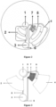
Figure 1 is a schematic structural view of a conventional microfluidic chip; -
Figure 2 is a schematic structural view of a microfluidic chip according to an embodiment of the present application; -
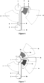
Figure 3 is a view of a mounting position of a first valve system for driving the fluid according to an embodiment of the present application; -
Figure 4 is a view of the mounting position of a second valve system for driving the fluid according to an embodiment of the present application; -
Figure 5 is a view of the mounting position of a third valve system for driving the fluid according to an embodiment of the present application; -
Figure 6 is a view of the mounting position of a fourth valve system for driving the fluid according to an embodiment of the present application; -
Figure 7 is a view of the mounting position of a fifth valve system for driving the fluid according to an embodiment of the present application; -
Figure 8 is a view of the mounting position of a sixth valve system for driving the fluid according to an embodiment of the present application; and -
Figure 9 is a specifically structural view of the microfluidic chip according to an embodiment of the present application. - Reference numerals in
Figures 1 to 9 . - 01 central position,
- 02 upstream fluid unit,
- 03 fluid unit far away from rotation center,
- 04 downstream fluid unit,
- 05 gas path passage,
- 1 rotation central position,
- 2 upstream fluid unit,
- 2a anterior cell lysis zone,
- 2b purification zone,
- 3 fluid unit far away from rotation center,
- 4 downstream fluid unit,
- 4a primary downstream fluid unit,
- 4b secondary downstream fluid unit,
- 4-1 first downstream fluid unit,
- 4-2 second downstream fluid unit,
- 5 gas path pipeline,
- 6 fluid pipeline,
- 6a primary fluid pipeline,
- 6b secondary fluid pipeline,
- 6-1 first fluid pipeline,
- 6-2 second fluid pipeline,
- 6-3 third fluid pipeline,
- 6-4 fourth fluid pipeline,
- 6-5 fifth fluid pipeline,
- 7 fluid unit close to rotation center,
- 7a primary fluid unit close to rotation center,
- 7b secondary fluid unit close to rotation center,
- 7-1 first fluid unit close to rotation center,
- 7-2 second fluid unit close to rotation center,
- 8 inlet passage far away rotation center,
- 9 outlet passage close to rotation center,
- 9a primary outlet passage close to rotation center,
- 9b secondary outlet passage close to rotation center.
- A core of the present application is to provide a valve system for driving the fluid, so as to reduce the size of a microfluidic chip in the direction of a rotation radius. And another core of the present application is to provide a method for using the valve system for driving the fluid.
- In order to enable the person skilled in the art to better understand the technical solution of the present application, the present application is further described in detail with reference to drawings and embodiments.
-
Figures 2 to 9 are referred. - In an embodiment of the present application, the valve system for driving the fluid according to a specific embodiment of the present application is applied to the microfluidic chip and includes a fluid unit far away from the
rotation center 3, a fluid unit close to therotation center 7, a fluid transferring unit and agas path pipeline 5 for communicating the fluid unit close to therotation center 7 with the fluid unit far away from therotation center 3. The fluid transferring unit is configured to drive fluid in the fluid unit far away from therotation center 3 into the fluid unit close to therotation center 7. The fluid unit close to therotation center 7 is located at a downstream of the fluid transferring unit, and the fluid transferring unit is afluid pipeline 6, as shown inFigures 2 to 8 . The rotation radius of a fluid outlet of the fluid unit far away from therotation center 3 is greater than the rotation radius of a fluid inlet of the fluid unit close to therotation center 7. In an embodiment, the rotation radius of the fluid outlet of the fluid unit far away from therotation center 3 is greater than the rotation radius of the fluid outlet of the fluid unit close to therotation center 7. Specifically, an inlet passage far away from therotation center 8 is provided outside the fluid inlet of the fluid unit far away from therotation center 3 to be connected with an external device for inputting the liquid. And an outlet passage close to therotation center 9 is provided outside the fluid outlet of the fluid unit close to therotation center 7 to output the liquid. - The fluid transferring unit is the
fluid pipeline 6, and a fluid inlet end of thefluid pipeline 6 is connected to the fluid outlet of the fluid unit far away from therotation center 3 and a fluid outlet end of thefluid pipeline 6 is connected to the fluid inlet of the fluid unit close to therotation center 7. Generally, the fluid unit far away from therotation center 3 is a fluid cell on the microfluidic chip at an intermediate link during multi-step liquid transfer, and the fluid cell is provided with at least one fluid inlet and at least one fluid outlet. - A suction force of the fluid unit close to the
rotation center 7 and a suction force of thefluid pipeline 6 are greater than a suction force of the fluid unit far away from therotation center 3. When the centrifugation stops, the liquid in the fluid unit far away from therotation center 3 is transferred into the fluid unit close to therotation center 7 via thefluid pipeline 6 under capillary action. - Specifically, the
gas path pipeline 5 is arranged between the fluid unit far away from the rotation center 3 (or an upstream fluid unit 2) and the fluid unit close to the rotation center 7 (or a downstream fluid unit 4). Specifically, one or moregas path pipelines 5 may be arranged. - Specifically, the fluid unit close to the
rotation center 7 is provided with a vent, and thegas path pipeline 5 is in communication with the vent. The vent is located at an end, close to the rotation center, of the fluid unit close to therotation center 7 and away from the fluid inlet of the fluid unit close to therotation center 7. - When the liquid is transferred along the
fluid pipeline 6 from the fluid unit far away from therotation center 3 into the fluid unit close to therotation center 7, thegas path pipeline 5 may balance the air pressure between the two fluid cells, thereby achieving continuously transfer of the liquid. - The fluid unit close to the
rotation center 7 or the downstream thereof is further provided with at least a gas communicating outlet, so as to achieve the communication of thegas path pipeline 5. - A micro array structure is provided on an inner wall of the fluid unit close to the
rotation center 7, and the micro array structure is circular, elliptic, polygonal or the like, which facilitates the fluid transfer. - Specifically, the micro array structure is provided on the inner wall of the
fluid pipeline 6, and the micro array structure may be circular, elliptic or polygonal. Specifically, the micro array structure may be triangular, quadrilateral or the like. Specifically, the micro array structure may be a rectangular structure when it is quadrilateral. - The fluid inlet end of the
fluid pipeline 6 is connected to the fluid outlet of the fluid unit far away from therotation center 3 and the fluid outlet end of thefluid pipeline 6 is connected to the fluid inlet of the fluid unit close to therotation center 7. - In a specific embodiment of the present application, the rotation radius of the fluid inlet of the fluid unit close to the
rotation center 7 is greater than the rotation radius of the fluid outlet of the fluid unit close to therotation center 7, so as to discharge the liquid to the downstream from the fluid unit close to therotation center 7 in time under the action of the centrifugal force. - Specifically, the fluid may be directly added into the fluid unit far away from the
rotation center 3 manually, or the fluid at the upstream of the fluid unit far away from therotation center 3 is transferred to the fluid unit far away from therotation center 3 under a certain external force, especially the centrifugal force. - Specifically, one or more valve systems for driving the fluid are arranged in the radial direction and the circumferential direction. Specifically, the valve systems for driving the fluid are arranged in the radial direction of the rotational direction of the microfluidic chip.
- When the valve system for driving the fluid works, first, the microfluidic chip keeps in static, the liquid in the fluid unit far away from the
rotation center 3 flows into thefluid pipeline 6 under the action of surface tension and reaches the fluid unit close to therotation center 7 through thefluid pipeline 6. The liquid flows into a downstream unit of the fluid unit close to therotation center 7 under the action of centrifugal force after flowing into the fluid unit close to therotation center 7. - Specifically, a
rotation center position 1 of the valve system for driving the fluid may be located inside a reactor or outside the reactor. - According to the above description, in the valve system for driving the fluid according to the present application, the liquid which is far from the
rotation center position 1 is transferred to the fluid unit close to therotation center 7 which is close to therotation center position 1 through thefluid pipeline 6, so as to realize liquid backflow to the end close to the rotation center, and make the downstream unit structure connected to the fluid unit close to therotation center 7 be close to the rotation center, thereby reducing the size of the microfluidic chip in the direction of the rotation radius. - The suction force of the fluid unit close to the
rotation center 7 and the suction force of thefluid pipeline 6 are greater than the suction force of the fluid unit far away from therotation center 3 during the backflow. The fluid transfer may be realized under capillary action without any external power, and the operation is simple, thus facilitating the fluid transfer in the microfluidic chip. - Specifically, the number of the
fluid pipeline 6 may be one, such as a first valve system for driving the fluid shown inFigure 3 , a third valve system for driving the fluid shown inFigure 5 and a fifth valve system for driving the fluid shown inFigure 7 . - In order to improve the efficiency of the fluid transfer, in an embodiment, the number of the
fluid pipeline 6 may be at least two, and each of the at least twofluid pipeline 6 is independently arranged. When threefluid pipelines 6 are provided, it is a second valve system for driving the fluid as shown inFigure 4 . Thefluid pipeline 6 includes a first fluid pipeline 6-1, a second fluid pipeline 6-2 and a third fluid pipeline 6-3 arranged in parallel. Specifically, the shape of a cross section of thefluid pipeline 6 is circular, elliptic or polygonal. When the cross section of thefluid pipeline 6 is polygonal, it may be rectangular or trapezoidal and the like. Certainly, the cross section of thefluid pipeline 6 may be set into other shapes according to actual needs. - The cross section of the
fluid pipeline 6 has an equivalent diameter from 0.01mm to 2mm. Specifically, the cross section of thefluid pipeline 6 has the equivalent diameter from 0.05mm to 1mm. The equivalent diameter of the cross section of thefluid pipeline 6 may be 0.05mm, 0.2mm, 0.5mm, 0.8mm and the like. The specific shape, size and number of thefluid pipeline 6 may be determined according to a required backflow rate of the fluid. - In a specific embodiment, the inner wall or a part of the inner wall of the
fluid pipeline 6 and/or the fluid unit close to therotation center 7 is an affinity-type surface. Specifically, the affinity-type surface may be a sodium dodecyl sulfate (SDS) layer, a polyethylene glycol octyl phenyl ether (Triton X-100) layer, an agarose layer, a tween (Tween80/Tween20) layer or a polypeptide layer. The affinity-type surface may also be a specific nano material or any component that may reduce a contact angle between the liquid and a pipe wall and is compatible with the reagent to be operated and subsequent reactions. The pipeline may be modified by pre modification such as chemical vapor deposition or coating with solution with surfactant and drying. The available surfactants include, but are not limited to Tween80, Tween20, TritonX-100, sugars, polypeptides and the like, or any component that may reduce the contact angle between the liquid and the pipe wall and is compatible with the reagent to be operated and subsequent reactions. - The inner wall or a part of the inner wall of the
fluid pipeline 6 and/or the fluid unit close to therotation center 7 performs an affinity-type surface treatment. For the liquid to pass through the inner wall, the contact angle between the liquid and a treated surface is less than the contact angle between the liquid and an untreated surface. The treated surface is more conducive for the liquid to flow in thefluid pipeline 6 driven by the surface tension, so as to be more conducive for the liquid to flow into thefluid pipeline 6 and reach the fluid unit close to therotation center 7 under the action of the surface tension. - In a specific embodiment, the fluid inlets of the fluid unit close to the
rotation center 7 respectively correspond to thefluid pipelines 6. Specifically, in an embodiment, the fluid inlet of the fluid unit close to therotation center 7 is arranged at an end of the fluid unit close to therotation center 7 close to the rotationcentral position 1, and the fluid outlet of the fluid unit close to therotation center 7 is arranged at an end of the fluid unit close to therotation center 7 away from the rotationcentral position 1. - Specifically, at least two fluid unit close to the rotation centers 7 are provided, and each of the at least two fluid unit close to the
rotation center 7 is independently arranged. The number of the fluid unit close to the rotation centers 7 is equal to the number of thefluid pipelines 6, and the fluid unit close to the rotation centers 7 respectively corresponds to thefluid pipelines 6. As shown inFigure 8 , a fourth fluid pipeline 6-4 is connected to a first fluid unit close to the rotation center 7-1, a fifth fluid pipeline 6-5 is connected to a second fluid unit close to the rotation center 7-2, the downstream of the first fluid unit close to the rotation center 7-1 is connected to a first downstream fluid unit 4-1, and the downstream of the second fluid unit close to the rotation center 7-2 is connected to a second downstream fluid unit 4-2. - A volume of a chamber of the fluid unit close to the
rotation center 7 is directly proportional to the volume of the fluid to be transferred. Therefore, the liquid may be quantitatively transferred by controlling the volume of the chamber of the fluid unit close to therotation center 7. - Specifically, the fluid unit close to the
rotation center 7 is a chamber or a segment of a fluid pipeline structure. Specifically, the fluid unit close to therotation center 7 is a thin chamber with a chamber height from 0.01mm to 2mm, and in an embodiment, the chamber height is from 0.05mm to 1mm, so that the fluid unit close to therotation center 7 maintains a certain capillary force. - In another specific embodiment, the fluid unit close to the
rotation center 7 is a fluid cell with a preset depth, and the fluid unit close to therotation center 7 is a thick chamber with the chamber height from 2mm to 10mm. Specifically, the fluid unit close to therotation center 7 is the fluid cell with the depth of 3mm, 4mm or 5mm and the like. - A fluid adsorbing structure is provided in the fluid unit close to the
rotation center 7, and the fluid absorbing structure does not react with a sample to be tested. That is, the material itself of the fluid adsorbing structure should have good chemical inertness for the adsorbed liquid, and the composition of the liquid is not easy to be changed after adsorption. Specifically, a certain mass of fluid adsorbing structure is accommodated in the fluid unit close to therotation center 7. - In order to improve the efficiency of the liquid transfer, in an embodiment, the fluid adsorbing structure directly contacts with or is close to the fluid inlet of the fluid unit close to the
rotation center 7. - Specifically, the fluid adsorbing structure in block-shaped or layer-shaped is arranged in the fluid unit close to the
rotation center 7. When the fluid adsorbing structure is in block-shaped, in an embodiment, multiple fluid adsorbing structures are provided. - When the fluid adsorbing structure is in layer-shaped, the fluid adsorbing structure may be porous absorbent paper, gauze, silicon dioxide fiber, sponge, collodion or the like. Preferably, the fluid adsorbing structure is multilayer overlapped. Since the porous materials such as absorbent paper, gauze, silicon dioxide fiber, sponge, collodion and the like are arranged, and the adsorbing materials generally may be selected with a good adsorbing capacity to the liquid, thereby improving the efficiency of the liquid transfer.
- When the fluid flows into the fluid unit close to the
rotation center 7, due to the absorption effect of the fluid absorbing structure, the liquid in the fluid unit far away from therotation center 3 will continuously flow into the fluid absorbing structure in the fluid unit close to therotation center 7 through thefluid pipeline 6 at a certain rate, until the liquid in the fluid unit far away from therotation center 3 is completely absorbed by the adsorbing material or the adsorbing material reaches saturation. - When the liquid transfer from an end far away from the rotation center to an end close to the rotation center is completed, under the action of the centrifugal force, the adsorbed liquid in the fluid unit close to the
rotation center 7 is released from the adsorbing material and flows into thedownstream fluid unit 4 through the fluid outlet. - In a specific embodiment, the volume of the fluid adsorbing structure in the fluid unit close to the
rotation center 7 is directly proportional to the volume of the fluid to be adsorbed. Therefore, the liquid may be quantitatively transferred by controlling the volume of the adsorbing material. - Specifically, as shown in
Figures 3 ,4 ,6 and 7 , the fluid unit close to therotation center 7 may be full of the fluid adsorption structure. As required, as shown inFigure 5 , the fluid adsorbing structure may also be quantitatively filled into the fluid unit close to therotation center 7 according to the volume of the liquid to be adsorbed. - According to the present application, the fluid transfer is realized by combining the simple surface tension with the water absorbing material, and the fluid is quantitatively transferred by controlling the volume of the fluid adsorbing structure, the transfer rate of the fluid is realized by controlling the size and number of the
fluid pipeline 6, and the method may completely transfer the fluid. - The present application has advantages as follows: 1, the structure is simple and facilitates processing and manufacturing. 2, additional driving force or special conditions don't need. 3, it is easy to be integrated and has good universality.
- When the valve system for driving the fluid is applied to the microfluidic chip, the valve system for driving the fluid is connected between the
upstream fluid unit 2 and thedownstream fluid unit 4. The fluid outlet of the fluid unit close to therotation center 7 is connected to the fluid inlet of thedownstream fluid unit 4 through the pipeline, and theupstream fluid unit 2 is located at the upstream of the fluid unit far away from therotation center 3. - Specifically, the
gas path pipeline 5 is in communication with the fluid unit far away from therotation center 3 through theupstream fluid unit 2, and thegas path pipeline 5 is in communication with thedownstream fluid unit 4 - In a specific embodiment, as shown in
Figure 7 , thedownstream fluid units 4 are multiple, and the two adjacent downstream fluid units are connected with each other through the valve system for driving the fluid. Thedownstream fluid unit 4 includes a primary downstreamfluid unit 4a and a secondary downstreamfluid unit 4b. At this time, the primary downstreamfluid unit 4a serves as the fluid unit far away from the rotation center of the valve system for driving the fluid between the two downstream fluid units. - The working process of the valve system for driving the fluid is introduced according to
Figure 9 hereinafter. At this time, the fluid unit far away from therotation center 3 serves as a mixing and pre amplification cell, and the fluid unit close to therotation center 7 serves as a nucleic acid reservoir, and thedownstream fluid unit 4 is a nucleic acid quantitative and amplification testing unit. The specific description of the working process of the valve system for driving the fluid on the microfluidic chip is as follows. - 1. An anterior
cell lysis zone 2a serves as a cell lysis zone. A sample to be tested is supplied into the lysis cell, and nucleic acid molecules are obtained by a certain lysis. - 2. A
purification zone 2b serves as a nucleic acid purification zone. The mixed nucleic acid obtained from the cell lysis zone passes through thepurification zone 2b to obtain high purity nucleic acid. - 3. The obtained high purity nucleic acid is transferred to the mixing and pre amplification cell by a certain centrifugal force.
- 4. The nucleic acid is transferred through the
fluid pipeline 6. Thefluid pipeline 6 has the length from 20mm to 40mm, and the width multiplied by the depth of the pipeline is about 0.1mm tolmm multiplied by 0.1mm tolmm. The number of thefluid pipelines 6 may be set to 1 to 5, which may be adjusted and determined according to the backflow rate of the fluid. The backflow time may be controlled within 10s to 90s, and the micro pipeline surface modification is performed, which may use the chemical modification, such as surfactant Tween80, Tween20, Triton X-100 and the like. - 5. A certain water absorbing material is placed in the nucleic acid reservoir. A silicon membrane which has strong water absorbing quality and good dehydration property may be used, and the high purity nucleic acid is transferred to the nucleic acid reservoir through the
fluid pipeline 6. - 6. Under a certain centrifugal force condition, the liquid in the nucleic acid reservoir flows into the nucleic acid quantitative and amplification testing unit. The nucleic acid quantitative and amplification testing unit includes a nucleic acid quantitative cell served as a primary downstream
fluid unit 4a and an amplification testing zone served as a secondary downstreamfluid unit 4b. - A method for using the valve system for driving the fluid is provided according to the present application, which is applied to the microfluidic chip. And the method includes:
- affinity modification is performed on the
fluid pipeline 6 and the fluid unit close to therotation center 7 by surfactant; - or, the surfactant is added to the liquid in the fluid unit far away from the
rotation center 3 in a case that thefluid pipeline 6 and the fluid unit close to therotation center 7 are non-affinity phenotype. - The surfactant includes, but is not limited to sodium dodecyl sulfate, polyethylene glycol octylphenol ether, agarose, polysorbate or polypeptide. Specifically, the surfactant may be a mixture of two of the above.
- The specific structure of the microfluidic chip has been described before. The present application includes the microfluidic chip, which also has the above technical effect. By providing the surfactant, the fluid is transferred quickly, and the working efficiency of the valve system for driving the fluid is effectively improved.
- The above embodiments are described in a progressive manner. Each of the embodiments is mainly focused on describing its differences from other embodiments, and references may be made among these embodiments with respect to the same or similar parts.
- The above description of the embodiments herein enables those skilled in the art to implement or use the present application. Various modifications to the embodiments are apparent to the person skilled in the art, and the general principle herein can be implemented in other embodiments without departing from the scope of the present application. The scope of the invention is defined in the appended claims.
Claims (13)
- A valve system for driving fluid, applied to a microfluidic chip, comprising:a fluid unit far away from a rotation center (3);a fluid unit close to the rotation center (7);a fluid transferring unit; anda gas path pipeline (5) for communicating the fluid unit close to the rotation center (7) with the fluid unit far away from the rotation center (3); and wherein,a rotation radius of a fluid outlet of the fluid unit far away from the rotation center (3) is greater than a rotation radius of a fluid inlet of the fluid unit close to the rotation center (7), the fluid outlet of the fluid unit far away from the rotation center (3) is located at an end, away from the rotation center, of the fluid unit far away from the rotation center (3), and the fluid inlet of the fluid unit close to the rotation center (7) is located at an end, close to the rotation center, of the fluid unit close to the rotation center (7);the fluid transferring unit is a fluid pipeline (6), a fluid inlet end of the fluid pipeline (6) is connected to the fluid outlet of the fluid unit far away from the rotation center (3) and a fluid outlet end of the fluid pipeline (6) is connected to the fluid inlet of the fluid unit close to the rotation center (7);said valve system characterized by a micro array structure which facilitates fluid transfer is provided on an inner wall of the fluid unit close to the rotation center (7) and/or an inner wall of the fluid pipeline (6), a suction force of the fluid unit close to the rotation center (7) and a suction force of the fluid pipeline (6) are greater than a suction force of the fluid unit far away from the rotation center (3), and liquid in the fluid unit far away from the rotation center (3) is transferred into the fluid unit close to the rotation center (7) via the fluid pipeline (6) under capillary action in a centrifugation stop state.
- The valve system for driving the fluid according to claim 1, wherein, a number of the fluid unit close to the rotation center (7) is one.
- The valve system for driving the fluid according to claim 1, wherein, the fluid unit close to the rotation center (7) is a chamber, and the chamber is a thin chamber with a chamber height from 0.01mm to 2mm or a thick chamber with the chamber height from 2mm to 10mm.
- The valve system for driving the fluid according to claim 1, wherein the fluid unit close to the rotation center (7) is a segment of the fluid pipeline structure, and a cross section of the fluid pipeline structure has an equivalent diameter from 0.01mm and 2mm.
- The valve system for driving the fluid according to claim 1, wherein the micro array structure is circular, elliptic or polygonal.
- The valve system for driving the fluid according to claim 1, wherein, a fluid adsorbing structure in block-shaped or layer-shaped is provided in the fluid unit close to the rotation center (7), and the fluid absorbing structure is not configured to react with a sample to be tested.
- The valve system for driving the fluid according to claim 1, wherein, the number of the fluid pipeline (6) is one.
- The valve system for driving the fluid according to claim 1, wherein the number of the fluid unit close to the rotation center (7) is at least two, and each of the at least two fluid unit close to the rotation centers (7) is independently arranged,a plurality of fluid pipelines (6) are provided, and each of the plurality of fluid pipelines (6) is independently arranged, andthe number of fluid unit close to the rotation centers is equal to the number of fluid pipelines (6), and each of the fluid unit close to the rotation centers (7) is connected to a respective one of the fluid pipelines (6).
- The valve system for driving the fluid according to claim 1, wherein, the shape of a cross section of the fluid pipeline (6) is rectangular, circular or elliptic, and the cross section of the fluid pipeline (6) has the equivalent diameter from 0.01mm to 2mm.
- The valve system for driving the fluid according to claim 1, wherein one or more valve systems for driving the fluid are arranged in a radial direction of a microfluidic chip and a circumferential direction of the microfluidic chip.
- The valve system for driving the fluid according to any one of claims 1 to 10, wherein a rotation central position (1) of the valve system for driving the fluid is located outside a reactor or inside the reactor.
- A method for using the valve system for driving fluid, applied to the valve system for driving the fluid according to any one of claims 1 to 11, comprising:performing affinity modification on a fluid pipeline (6) and a fluid unit close to the rotation center (7) by surfactant;or, adding the surfactant to liquid in a fluid unit far away from the rotation center (3) in a case that the fluid pipeline (6) and the fluid unit close to the rotation center (7) are non-affinity phenotype.
- The method for using the valve system for driving the fluid according to claim 12, wherein:
the surfactant is sodium dodecyl sulfate and/or polyethylene glycol octylphenol ether and/or agarose and/or polysorbate and/or polypeptide.
Applications Claiming Priority (1)
| Application Number | Priority Date | Filing Date | Title |
|---|---|---|---|
| CN202010308400.4A CN111207242B (en) | 2020-04-18 | 2020-04-18 | Fluid actuated control valve and method of use |
Publications (2)
| Publication Number | Publication Date |
|---|---|
| EP3895801A1 EP3895801A1 (en) | 2021-10-20 |
| EP3895801B1 true EP3895801B1 (en) | 2025-02-26 |
Family
ID=70784731
Family Applications (1)
| Application Number | Title | Priority Date | Filing Date |
|---|---|---|---|
| EP21151493.0A Active EP3895801B1 (en) | 2020-04-18 | 2021-01-14 | Valve system for driving fluid and method for using the same |
Country Status (3)
| Country | Link |
|---|---|
| US (1) | US11565255B2 (en) |
| EP (1) | EP3895801B1 (en) |
| CN (1) | CN111207242B (en) |
Families Citing this family (1)
| Publication number | Priority date | Publication date | Assignee | Title |
|---|---|---|---|---|
| CN115074230B (en) * | 2022-07-21 | 2023-05-23 | 北京泰豪生物科技有限公司 | Reagent controlled release module, bioreactor and biological detection device |
Citations (1)
| Publication number | Priority date | Publication date | Assignee | Title |
|---|---|---|---|---|
| US20110263030A1 (en) * | 2010-01-29 | 2011-10-27 | Samsung Electronics Co., Ltd. | Centrifugal micro-fluidic device and method for detecting analytes from liquid specimen |
Family Cites Families (10)
| Publication number | Priority date | Publication date | Assignee | Title |
|---|---|---|---|---|
| EP0983504A2 (en) * | 1997-05-23 | 2000-03-08 | Gamera Bioscience Corporation | Devices and methods for using centripetal acceleration to drive fluid movement in a microfluidics system |
| US20090169430A1 (en) * | 2006-04-04 | 2009-07-02 | Matsushita Electric Industrial Co., Ltd. | Panel for analyzing sample liquid |
| EP1916524A1 (en) * | 2006-09-27 | 2008-04-30 | Roche Diagnostics GmbH | Rotatable test element |
| CN103217539B (en) * | 2007-10-30 | 2015-07-22 | 松下健康医疗器械株式会社 | Analyzing device and analyzing method |
| EP2138232A1 (en) * | 2008-06-23 | 2009-12-30 | Koninklijke Philips Electronics N.V. | Detection of tapped aliquots of amplified nucleic acids |
| WO2011011350A2 (en) * | 2009-07-20 | 2011-01-27 | Siloam Biosciences, Inc. | Microfluidic assay platforms |
| CN105886386B (en) * | 2016-04-06 | 2018-05-04 | 苏州汶颢芯片科技有限公司 | High throughput bacterium colony detection chip, detecting system and detection method |
| CN107398307B (en) * | 2016-05-18 | 2023-07-25 | 博奥生物集团有限公司 | An integrated microfluidic chip |
| CN106268994B (en) * | 2016-09-22 | 2018-04-20 | 博奥生物集团有限公司 | A kind of centrifugal type microfludic chip |
| CN110777049A (en) * | 2019-11-12 | 2020-02-11 | 北京金豪制药股份有限公司 | Microfluidic chip, nucleic acid detector and nucleic acid detection method |
-
2020
- 2020-04-18 CN CN202010308400.4A patent/CN111207242B/en active Active
-
2021
- 2021-01-14 EP EP21151493.0A patent/EP3895801B1/en active Active
- 2021-02-05 US US17/168,763 patent/US11565255B2/en active Active
Patent Citations (1)
| Publication number | Priority date | Publication date | Assignee | Title |
|---|---|---|---|---|
| US20110263030A1 (en) * | 2010-01-29 | 2011-10-27 | Samsung Electronics Co., Ltd. | Centrifugal micro-fluidic device and method for detecting analytes from liquid specimen |
Also Published As
| Publication number | Publication date |
|---|---|
| US11565255B2 (en) | 2023-01-31 |
| CN111207242B (en) | 2020-09-01 |
| CN111207242A (en) | 2020-05-29 |
| EP3895801A1 (en) | 2021-10-20 |
| US20210322983A1 (en) | 2021-10-21 |
Similar Documents
| Publication | Publication Date | Title |
|---|---|---|
| JP5250669B2 (en) | Microfluidic structure, pathogen detection system and method for pathogen analysis | |
| Peterson | Solid supports for micro analytical systems | |
| CN114717100B (en) | Microfluidic chip for single-cell sequencing and application | |
| CN100537219C (en) | Method and apparatus for detecting and analyzing pathogens | |
| CN102989533B (en) | Micro-fluidic chip for high-flux automatically rationing and mixing and use method and application of chip | |
| CN110180610B (en) | Reagent sequential loading method and structure and microfluidic device | |
| KR20040019869A (en) | Cascaded hydrodynamic focusing in microfluidic channels | |
| CN211586663U (en) | A biological detection chip | |
| CN110885749A (en) | Virus detection system and micro-fluidic chip thereof | |
| CN117007800B (en) | Dual-droplet microfluidic chip for escherichia coli detection and application thereof | |
| EP1645882A1 (en) | Chemical analyzer and a structure to be used in the analyzer | |
| CN113967492B (en) | Multipurpose centrifugal microfluidic chip | |
| EP3895801A1 (en) | Valve system for driving fluid and method for using the same | |
| Wang et al. | A chip-to-chip nanoliter microfluidic dispenser | |
| CN111389474B (en) | A microfluidic chip for sample dispersion and its preparation method and application | |
| JP4819945B2 (en) | Substrate having flow path part including chamber, and method of transferring liquid using the same | |
| CN219273091U (en) | Reaction chip and detection equipment | |
| CN110260026A (en) | Siphon valve arrangement and centrifugal microfluidic control device are assisted in air pressure | |
| JP2013509578A (en) | Siphon aspiration as a cleaning method and device for heterogeneous assays | |
| CN210600427U (en) | Fluid-driven control valve | |
| Li et al. | One-step liquid molding based modular microfluidic circuits | |
| CN211972335U (en) | Virus detection system and micro-fluidic chip thereof | |
| CN109806803B (en) | Microfluid mixing device with electrowetting valve and control method thereof | |
| Carlier et al. | High pressure-resistant SU-8 microchannels for monolithic porous structure integration | |
| CN108212230B (en) | Droplet generation device and method based on micro-valve control |
Legal Events
| Date | Code | Title | Description |
|---|---|---|---|
| PUAI | Public reference made under article 153(3) epc to a published international application that has entered the european phase |
Free format text: ORIGINAL CODE: 0009012 |
|
| STAA | Information on the status of an ep patent application or granted ep patent |
Free format text: STATUS: THE APPLICATION HAS BEEN PUBLISHED |
|
| AK | Designated contracting states |
Kind code of ref document: A1 Designated state(s): AL AT BE BG CH CY CZ DE DK EE ES FI FR GB GR HR HU IE IS IT LI LT LU LV MC MK MT NL NO PL PT RO RS SE SI SK SM TR |
|
| B565 | Issuance of search results under rule 164(2) epc |
Effective date: 20210708 |
|
| STAA | Information on the status of an ep patent application or granted ep patent |
Free format text: STATUS: REQUEST FOR EXAMINATION WAS MADE |
|
| 17P | Request for examination filed |
Effective date: 20211203 |
|
| RBV | Designated contracting states (corrected) |
Designated state(s): AL AT BE BG CH CY CZ DE DK EE ES FI FR GB GR HR HU IE IS IT LI LT LU LV MC MK MT NL NO PL PT RO RS SE SI SK SM TR |
|
| STAA | Information on the status of an ep patent application or granted ep patent |
Free format text: STATUS: EXAMINATION IS IN PROGRESS |
|
| 17Q | First examination report despatched |
Effective date: 20230626 |
|
| GRAP | Despatch of communication of intention to grant a patent |
Free format text: ORIGINAL CODE: EPIDOSNIGR1 |
|
| STAA | Information on the status of an ep patent application or granted ep patent |
Free format text: STATUS: GRANT OF PATENT IS INTENDED |
|
| INTG | Intention to grant announced |
Effective date: 20240809 |
|
| GRAS | Grant fee paid |
Free format text: ORIGINAL CODE: EPIDOSNIGR3 |
|
| GRAA | (expected) grant |
Free format text: ORIGINAL CODE: 0009210 |
|
| STAA | Information on the status of an ep patent application or granted ep patent |
Free format text: STATUS: THE PATENT HAS BEEN GRANTED |
|
| AK | Designated contracting states |
Kind code of ref document: B1 Designated state(s): AL AT BE BG CH CY CZ DE DK EE ES FI FR GB GR HR HU IE IS IT LI LT LU LV MC MK MT NL NO PL PT RO RS SE SI SK SM TR |
|
| REG | Reference to a national code |
Ref country code: GB Ref legal event code: FG4D |
|
| REG | Reference to a national code |
Ref country code: CH Ref legal event code: EP |
|
| REG | Reference to a national code |
Ref country code: DE Ref legal event code: R096 Ref document number: 602021026598 Country of ref document: DE |
|
| REG | Reference to a national code |
Ref country code: IE Ref legal event code: FG4D |
|
| REG | Reference to a national code |
Ref country code: NL Ref legal event code: MP Effective date: 20250226 |
|
| PG25 | Lapsed in a contracting state [announced via postgrant information from national office to epo] |
Ref country code: RS Free format text: LAPSE BECAUSE OF FAILURE TO SUBMIT A TRANSLATION OF THE DESCRIPTION OR TO PAY THE FEE WITHIN THE PRESCRIBED TIME-LIMIT Effective date: 20250526 |
|
| PG25 | Lapsed in a contracting state [announced via postgrant information from national office to epo] |
Ref country code: FI Free format text: LAPSE BECAUSE OF FAILURE TO SUBMIT A TRANSLATION OF THE DESCRIPTION OR TO PAY THE FEE WITHIN THE PRESCRIBED TIME-LIMIT Effective date: 20250226 |
|
| PG25 | Lapsed in a contracting state [announced via postgrant information from national office to epo] |
Ref country code: PL Free format text: LAPSE BECAUSE OF FAILURE TO SUBMIT A TRANSLATION OF THE DESCRIPTION OR TO PAY THE FEE WITHIN THE PRESCRIBED TIME-LIMIT Effective date: 20250226 |
|
| PG25 | Lapsed in a contracting state [announced via postgrant information from national office to epo] |
Ref country code: ES Free format text: LAPSE BECAUSE OF FAILURE TO SUBMIT A TRANSLATION OF THE DESCRIPTION OR TO PAY THE FEE WITHIN THE PRESCRIBED TIME-LIMIT Effective date: 20250226 |
|
| REG | Reference to a national code |
Ref country code: LT Ref legal event code: MG9D |
|
| PG25 | Lapsed in a contracting state [announced via postgrant information from national office to epo] |
Ref country code: IS Free format text: LAPSE BECAUSE OF FAILURE TO SUBMIT A TRANSLATION OF THE DESCRIPTION OR TO PAY THE FEE WITHIN THE PRESCRIBED TIME-LIMIT Effective date: 20250626 Ref country code: NO Free format text: LAPSE BECAUSE OF FAILURE TO SUBMIT A TRANSLATION OF THE DESCRIPTION OR TO PAY THE FEE WITHIN THE PRESCRIBED TIME-LIMIT Effective date: 20250526 |
|
| PG25 | Lapsed in a contracting state [announced via postgrant information from national office to epo] |
Ref country code: NL Free format text: LAPSE BECAUSE OF FAILURE TO SUBMIT A TRANSLATION OF THE DESCRIPTION OR TO PAY THE FEE WITHIN THE PRESCRIBED TIME-LIMIT Effective date: 20250226 |
|
| PG25 | Lapsed in a contracting state [announced via postgrant information from national office to epo] |
Ref country code: HR Free format text: LAPSE BECAUSE OF FAILURE TO SUBMIT A TRANSLATION OF THE DESCRIPTION OR TO PAY THE FEE WITHIN THE PRESCRIBED TIME-LIMIT Effective date: 20250226 |
|
| PG25 | Lapsed in a contracting state [announced via postgrant information from national office to epo] |
Ref country code: PT Free format text: LAPSE BECAUSE OF FAILURE TO SUBMIT A TRANSLATION OF THE DESCRIPTION OR TO PAY THE FEE WITHIN THE PRESCRIBED TIME-LIMIT Effective date: 20250626 Ref country code: LV Free format text: LAPSE BECAUSE OF FAILURE TO SUBMIT A TRANSLATION OF THE DESCRIPTION OR TO PAY THE FEE WITHIN THE PRESCRIBED TIME-LIMIT Effective date: 20250226 |
|
| PG25 | Lapsed in a contracting state [announced via postgrant information from national office to epo] |
Ref country code: BG Free format text: LAPSE BECAUSE OF FAILURE TO SUBMIT A TRANSLATION OF THE DESCRIPTION OR TO PAY THE FEE WITHIN THE PRESCRIBED TIME-LIMIT Effective date: 20250226 Ref country code: GR Free format text: LAPSE BECAUSE OF FAILURE TO SUBMIT A TRANSLATION OF THE DESCRIPTION OR TO PAY THE FEE WITHIN THE PRESCRIBED TIME-LIMIT Effective date: 20250527 |
|
| REG | Reference to a national code |
Ref country code: AT Ref legal event code: MK05 Ref document number: 1770131 Country of ref document: AT Kind code of ref document: T Effective date: 20250226 |
|
| PG25 | Lapsed in a contracting state [announced via postgrant information from national office to epo] |
Ref country code: SE Free format text: LAPSE BECAUSE OF FAILURE TO SUBMIT A TRANSLATION OF THE DESCRIPTION OR TO PAY THE FEE WITHIN THE PRESCRIBED TIME-LIMIT Effective date: 20250226 |
|
| PG25 | Lapsed in a contracting state [announced via postgrant information from national office to epo] |
Ref country code: SM Free format text: LAPSE BECAUSE OF FAILURE TO SUBMIT A TRANSLATION OF THE DESCRIPTION OR TO PAY THE FEE WITHIN THE PRESCRIBED TIME-LIMIT Effective date: 20250226 |
|
| PG25 | Lapsed in a contracting state [announced via postgrant information from national office to epo] |
Ref country code: DK Free format text: LAPSE BECAUSE OF FAILURE TO SUBMIT A TRANSLATION OF THE DESCRIPTION OR TO PAY THE FEE WITHIN THE PRESCRIBED TIME-LIMIT Effective date: 20250226 |
|
| PG25 | Lapsed in a contracting state [announced via postgrant information from national office to epo] |
Ref country code: IT Free format text: LAPSE BECAUSE OF FAILURE TO SUBMIT A TRANSLATION OF THE DESCRIPTION OR TO PAY THE FEE WITHIN THE PRESCRIBED TIME-LIMIT Effective date: 20250226 |
|
| PG25 | Lapsed in a contracting state [announced via postgrant information from national office to epo] |
Ref country code: AT Free format text: LAPSE BECAUSE OF FAILURE TO SUBMIT A TRANSLATION OF THE DESCRIPTION OR TO PAY THE FEE WITHIN THE PRESCRIBED TIME-LIMIT Effective date: 20250226 |
|
| PG25 | Lapsed in a contracting state [announced via postgrant information from national office to epo] |
Ref country code: EE Free format text: LAPSE BECAUSE OF FAILURE TO SUBMIT A TRANSLATION OF THE DESCRIPTION OR TO PAY THE FEE WITHIN THE PRESCRIBED TIME-LIMIT Effective date: 20250226 Ref country code: CZ Free format text: LAPSE BECAUSE OF FAILURE TO SUBMIT A TRANSLATION OF THE DESCRIPTION OR TO PAY THE FEE WITHIN THE PRESCRIBED TIME-LIMIT Effective date: 20250226 |
|
| PG25 | Lapsed in a contracting state [announced via postgrant information from national office to epo] |
Ref country code: RO Free format text: LAPSE BECAUSE OF FAILURE TO SUBMIT A TRANSLATION OF THE DESCRIPTION OR TO PAY THE FEE WITHIN THE PRESCRIBED TIME-LIMIT Effective date: 20250226 |
|
| PG25 | Lapsed in a contracting state [announced via postgrant information from national office to epo] |
Ref country code: SK Free format text: LAPSE BECAUSE OF FAILURE TO SUBMIT A TRANSLATION OF THE DESCRIPTION OR TO PAY THE FEE WITHIN THE PRESCRIBED TIME-LIMIT Effective date: 20250226 |
|
| REG | Reference to a national code |
Ref country code: DE Ref legal event code: R097 Ref document number: 602021026598 Country of ref document: DE |
|
| PLBE | No opposition filed within time limit |
Free format text: ORIGINAL CODE: 0009261 |
|
| STAA | Information on the status of an ep patent application or granted ep patent |
Free format text: STATUS: NO OPPOSITION FILED WITHIN TIME LIMIT |
|
| REG | Reference to a national code |
Ref country code: DE Ref legal event code: R081 Ref document number: 602021026598 Country of ref document: DE Owner name: CAPITALBIO CORPORATION, CN Free format text: FORMER OWNERS: CAPITALBIO CORPORATION, CHANGPING DISTRICT BEIJING, CN; WEST CHINA HOSPITAL SICHUAN UNIVERSITY, CHENGDU, SICHUAN, CN Ref country code: DE Ref legal event code: R081 Ref document number: 602021026598 Country of ref document: DE Owner name: TSINGHUA UNIVERSITY, CN Free format text: FORMER OWNERS: CAPITALBIO CORPORATION, CHANGPING DISTRICT BEIJING, CN; WEST CHINA HOSPITAL SICHUAN UNIVERSITY, CHENGDU, SICHUAN, CN Ref country code: DE Ref legal event code: R081 Ref document number: 602021026598 Country of ref document: DE Owner name: WEST CHINA HOSPITAL SICHUAN UNIVERSITY, CHENGD, CN Free format text: FORMER OWNERS: CAPITALBIO CORPORATION, CHANGPING DISTRICT BEIJING, CN; WEST CHINA HOSPITAL SICHUAN UNIVERSITY, CHENGDU, SICHUAN, CN |
|
| 26N | No opposition filed |
Effective date: 20251127 |
|
| REG | Reference to a national code |
Ref country code: GB Ref legal event code: 732E Free format text: REGISTERED BETWEEN 20260108 AND 20260114 |
|
| PGFP | Annual fee paid to national office [announced via postgrant information from national office to epo] |
Ref country code: GB Payment date: 20260107 Year of fee payment: 6 |
|
| PGFP | Annual fee paid to national office [announced via postgrant information from national office to epo] |
Ref country code: DE Payment date: 20260121 Year of fee payment: 6 |