EP3895754A1 - Sheet-shaped object attaching device - Google Patents
Sheet-shaped object attaching device Download PDFInfo
- Publication number
- EP3895754A1 EP3895754A1 EP19904565.9A EP19904565A EP3895754A1 EP 3895754 A1 EP3895754 A1 EP 3895754A1 EP 19904565 A EP19904565 A EP 19904565A EP 3895754 A1 EP3895754 A1 EP 3895754A1
- Authority
- EP
- European Patent Office
- Prior art keywords
- sheet
- shaped object
- support
- support body
- shaped
- Prior art date
- Legal status (The legal status is an assumption and is not a legal conclusion. Google has not performed a legal analysis and makes no representation as to the accuracy of the status listed.)
- Withdrawn
Links
Images


Classifications
-
- A—HUMAN NECESSITIES
- A61—MEDICAL OR VETERINARY SCIENCE; HYGIENE
- A61B—DIAGNOSIS; SURGERY; IDENTIFICATION
- A61B17/00—Surgical instruments, devices or methods
- A61B17/0057—Implements for plugging an opening in the wall of a hollow or tubular organ, e.g. for sealing a vessel puncture or closing a cardiac septal defect
-
- A—HUMAN NECESSITIES
- A61—MEDICAL OR VETERINARY SCIENCE; HYGIENE
- A61F—FILTERS IMPLANTABLE INTO BLOOD VESSELS; PROSTHESES; DEVICES PROVIDING PATENCY TO, OR PREVENTING COLLAPSING OF, TUBULAR STRUCTURES OF THE BODY, e.g. STENTS; ORTHOPAEDIC, NURSING OR CONTRACEPTIVE DEVICES; FOMENTATION; TREATMENT OR PROTECTION OF EYES OR EARS; BANDAGES, DRESSINGS OR ABSORBENT PADS; FIRST-AID KITS
- A61F2/00—Filters implantable into blood vessels; Prostheses, i.e. artificial substitutes or replacements for parts of the body; Appliances for connecting them with the body; Devices providing patency to, or preventing collapsing of, tubular structures of the body, e.g. stents
- A61F2/0063—Implantable repair or support meshes, e.g. hernia meshes
-
- A—HUMAN NECESSITIES
- A61—MEDICAL OR VETERINARY SCIENCE; HYGIENE
- A61B—DIAGNOSIS; SURGERY; IDENTIFICATION
- A61B17/00—Surgical instruments, devices or methods
- A61B17/0057—Implements for plugging an opening in the wall of a hollow or tubular organ, e.g. for sealing a vessel puncture or closing a cardiac septal defect
- A61B2017/00575—Implements for plugging an opening in the wall of a hollow or tubular organ, e.g. for sealing a vessel puncture or closing a cardiac septal defect for closure at remote site, e.g. closing atrial septum defects
-
- A—HUMAN NECESSITIES
- A61—MEDICAL OR VETERINARY SCIENCE; HYGIENE
- A61B—DIAGNOSIS; SURGERY; IDENTIFICATION
- A61B17/00—Surgical instruments, devices or methods
- A61B17/0057—Implements for plugging an opening in the wall of a hollow or tubular organ, e.g. for sealing a vessel puncture or closing a cardiac septal defect
- A61B2017/00575—Implements for plugging an opening in the wall of a hollow or tubular organ, e.g. for sealing a vessel puncture or closing a cardiac septal defect for closure at remote site, e.g. closing atrial septum defects
- A61B2017/0061—Implements located only on one side of the opening
-
- A—HUMAN NECESSITIES
- A61—MEDICAL OR VETERINARY SCIENCE; HYGIENE
- A61B—DIAGNOSIS; SURGERY; IDENTIFICATION
- A61B17/00—Surgical instruments, devices or methods
- A61B17/0057—Implements for plugging an opening in the wall of a hollow or tubular organ, e.g. for sealing a vessel puncture or closing a cardiac septal defect
- A61B2017/00575—Implements for plugging an opening in the wall of a hollow or tubular organ, e.g. for sealing a vessel puncture or closing a cardiac septal defect for closure at remote site, e.g. closing atrial septum defects
- A61B2017/00623—Introducing or retrieving devices therefor
-
- A—HUMAN NECESSITIES
- A61—MEDICAL OR VETERINARY SCIENCE; HYGIENE
- A61B—DIAGNOSIS; SURGERY; IDENTIFICATION
- A61B17/00—Surgical instruments, devices or methods
- A61B17/0057—Implements for plugging an opening in the wall of a hollow or tubular organ, e.g. for sealing a vessel puncture or closing a cardiac septal defect
- A61B2017/00676—Implements for plugging an opening in the wall of a hollow or tubular organ, e.g. for sealing a vessel puncture or closing a cardiac septal defect promotion of self-sealing of the puncture
-
- A—HUMAN NECESSITIES
- A61—MEDICAL OR VETERINARY SCIENCE; HYGIENE
- A61B—DIAGNOSIS; SURGERY; IDENTIFICATION
- A61B17/00—Surgical instruments, devices or methods
- A61B2017/00831—Material properties
- A61B2017/0084—Material properties low friction
- A61B2017/00849—Material properties low friction with respect to tissue, e.g. hollow organs
-
- A—HUMAN NECESSITIES
- A61—MEDICAL OR VETERINARY SCIENCE; HYGIENE
- A61B—DIAGNOSIS; SURGERY; IDENTIFICATION
- A61B17/00—Surgical instruments, devices or methods
- A61B2017/00831—Material properties
- A61B2017/00884—Material properties enhancing wound closure
-
- A—HUMAN NECESSITIES
- A61—MEDICAL OR VETERINARY SCIENCE; HYGIENE
- A61B—DIAGNOSIS; SURGERY; IDENTIFICATION
- A61B17/00—Surgical instruments, devices or methods
- A61B2017/00831—Material properties
- A61B2017/00951—Material properties adhesive
-
- A—HUMAN NECESSITIES
- A61—MEDICAL OR VETERINARY SCIENCE; HYGIENE
- A61F—FILTERS IMPLANTABLE INTO BLOOD VESSELS; PROSTHESES; DEVICES PROVIDING PATENCY TO, OR PREVENTING COLLAPSING OF, TUBULAR STRUCTURES OF THE BODY, e.g. STENTS; ORTHOPAEDIC, NURSING OR CONTRACEPTIVE DEVICES; FOMENTATION; TREATMENT OR PROTECTION OF EYES OR EARS; BANDAGES, DRESSINGS OR ABSORBENT PADS; FIRST-AID KITS
- A61F2/00—Filters implantable into blood vessels; Prostheses, i.e. artificial substitutes or replacements for parts of the body; Appliances for connecting them with the body; Devices providing patency to, or preventing collapsing of, tubular structures of the body, e.g. stents
- A61F2/0063—Implantable repair or support meshes, e.g. hernia meshes
- A61F2002/0072—Delivery tools therefor
-
- A—HUMAN NECESSITIES
- A61—MEDICAL OR VETERINARY SCIENCE; HYGIENE
- A61F—FILTERS IMPLANTABLE INTO BLOOD VESSELS; PROSTHESES; DEVICES PROVIDING PATENCY TO, OR PREVENTING COLLAPSING OF, TUBULAR STRUCTURES OF THE BODY, e.g. STENTS; ORTHOPAEDIC, NURSING OR CONTRACEPTIVE DEVICES; FOMENTATION; TREATMENT OR PROTECTION OF EYES OR EARS; BANDAGES, DRESSINGS OR ABSORBENT PADS; FIRST-AID KITS
- A61F2250/00—Special features of prostheses classified in groups A61F2/00 - A61F2/26 or A61F2/82 or A61F9/00 or A61F11/00 or subgroups thereof
- A61F2250/0014—Special features of prostheses classified in groups A61F2/00 - A61F2/26 or A61F2/82 or A61F9/00 or A61F11/00 or subgroups thereof having different values of a given property or geometrical feature, e.g. mechanical property or material property, at different locations within the same prosthesis
- A61F2250/0021—Special features of prostheses classified in groups A61F2/00 - A61F2/26 or A61F2/82 or A61F9/00 or A61F11/00 or subgroups thereof having different values of a given property or geometrical feature, e.g. mechanical property or material property, at different locations within the same prosthesis differing in coefficient of friction
Definitions
- the present invention relates to a device for attaching a sheet-shaped object to a target site and a method for attaching a sheet-shaped object using the device.
- Non Patent Literature 1 Non Patent Literature 1
- Non Patent Literature 2 a cell structure formed by using a scaffold and a sheet-shaped cell culture in which cells are formed in a sheet shape have been developed.
- a cultured epidermis sheet for skin damage caused by burns and the like use of a corneal epithelial sheet-shaped cell culture for corneal damage, use of an oral mucosal sheet-shaped cell culture for endoscopic resection of esophageal cancer, and the like have been studied, and some of these are in a stage of clinical application.
- a transporting/administering instrument described in Patent Literature 1 can transport a sheet-shaped therapeutic substance up to a transplant site by forming a seat support member into a tubular shape and storing the seat support member in an outer cylinder to reduce the degree of invasion to a human body.
- a sheet attaching device described in Patent Literature 2 detaches a rod-shaped member disposed along a surface of a sheet support portion by moving the rod-shaped member along the surface of the sheet support portion, and can attach the sheet-shaped substance to a target site.
- a transporting/administering instrument described in Patent Literature 3 can administer a sheet using a sheet attachment/detachment means capable of applying a negative pressure for attaching and holding a sheet-shaped therapeutic substance to a sheet support and a positive pressure for detaching the sheet-shaped therapeutic substance from the sheet support.
- a conveyance instrument described in Patent Literature 4 can attach a sheet-shaped therapeutic substance by ejecting a fluid from a plurality of vents formed on a surface of a head holding the sheet-shaped therapeutic substance.
- an object of the present invention is to solve such a problem and to achieve a rational device having a simple configuration and.
- the present invention relates to the following.
- a sheet-shaped object can be efficiently attached to a target site by a simple mechanism and a simple operation. Therefore, there are large advantages in terms of operability and manufacturing cost.
- the sheet-shaped object can be detached stepwise. Therefore, by detaching a part of the sheet-shaped object, positioning and attaching the part of the sheet-shaped object to a target site, and then detaching the other parts stepwise, generation of wrinkles and the like can be prevented. In particular, by detaching the sheet-shaped object with a fluid, occurrence of defects and the like can be prevented, and the sheet-shaped object can be efficiently attached while the shape of the sheet-shaped object is maintained.
- a "sheet-shaped object” in the present invention refers to a sheet-shaped object that has low physical strength and may be torn, broken, deformed, or the like, for example, by being detached from a device.
- a sheet-shaped object is not particularly limited, but examples thereof include a sheet-shaped structure, for example, a flat membrane-like membrane tissue made of a biological material such as a sheet-shaped cell culture, and films made of various materials such as plastic, paper, woven fabric, non-woven fabric, metal, polymer, and lipid.
- the sheet-shaped structure may be polygonal, circular, or the like, and the width, thickness, diameter, and the like of the sheet-shaped structure may be uniform or non-uniform.
- the sheet-shaped structure in the present invention only one sheet may be used in a single layer state, or two or more sheets may be overlapped with each other to be used in a state of a laminate.
- the layers of the laminate may be connected to each other, or do not have to be connected to each other.
- all overlapping portions may be connected, or overlapping portions may be partially connected.
- the "sheet-shaped cell culture” refers to an object obtained by connecting cells to each other to form a sheet.
- the cells may be connected to each other directly (including a case where cells are connected to each other via a cell element such as an adhesion molecule) and/or via an intervening substance.
- the intervening substance is not particularly limited as long as being a substance capable of connecting cells to each other at least physically (mechanically), but examples thereof include an extracellular matrix.
- the intervening substance is preferably derived from cells, and particularly preferably derived from cells constituting a cell culture.
- the cells are connected to each other at least physically (mechanically), but may be connected to each other more functionally, for example, chemically or electrically.
- the sheet-shaped cell culture may be constituted by one cell layer (single layer) or two or more cell layers (laminated (multilayer) body, for example, two layers, three layers, four layers, five layers, or six layers).
- the sheet-shaped cell culture may have a three-dimensional structure having a thickness exceeding the thickness of one cell without a clear layered structure of cells.
- cells may be present in a non-uniform (for example, mosaic-like) arrangement without being uniformly aligned in the horizontal direction.
- the sheet-shaped cell culture preferably contains no scaffold (support).
- the scaffold may be used in the present technical field in order to attach cells to a surface thereof and/or an inside thereof and maintain physical integrity of the sheet-shaped cell culture.
- PVDF polyvinylidene fluoride
- the sheet-shaped cell culture of the present invention can maintain physical integrity thereof even without such a scaffold.
- the sheet-shaped cell culture of the present invention preferably contains only a substance derived from cells constituting the sheet-shaped cell culture, and contains no other substance.
- the cells constituting the sheet-shaped cell culture are not particularly limited as long as being able to form the sheet-shaped cell culture, and include, for example, an adherent cell (adhesive cell).
- the adherent cell includes, for example, an adherent somatic cell (for example, a cardiomyocyte, a fibroblast cell, an epithelial cell, an endothelial cell, a hepatocyte, a pancreatic cell, a kidney cell (a renal cell), an adrenal cell, a periodontal membrane cell, a gingival cell, a bone membrane cell, a skin cell, a synovial cell, or a chondrocyte) and a stem cell (for example, a tissue stem cell such as a myoblast or a cardiac stem cell, an embryonic stem cell, a pluripotent stem cell such as an induced pluripotent stem (iPS) cell, or a mesenchymal stem cell).
- an adherent somatic cell for example, a cardiomyocyte
- the somatic cell may be a stem cell, particularly a cell differentiated from an iPS cell (iPS cell-derived adherent cell).
- the cells constituting the sheet-shaped cell culture include a myoblast (for example, a myoblast cell), a mesenchymal stem cell (for example, those derived from bone marrow, an adipose tissue, peripheral blood, skin, a hair root, a muscle tissue, an endometrial membrane, placenta, and umbilical cord blood), a cardiomyocyte, a fibroblast cell, a heart stem cell, an embryonic stem cell, an iPS cell, a synovial cell, a chondrocyte, an epithelial cell (for example, an oral mucosal epithelial cell, a retinal pigment epithelial cell, or a nasal mucosal epithelial cell), an endothelial cell (for example, a vascular endothelial cell), a hepatocyte (for example,
- Non-limiting examples of the iPS cell-derived adherent cell include a cardiomyocyte, a fibroblast cell, an epithelial cell, an endothelial cell, a hepatocyte, a pancreatic cell, a renal cell, an adrenal cell, a periodontal membrane cell, a gingival cell, a bone membrane cell, a skin cell, a synovial cell, a chondrocyte, derived from an iPS cell.
- the "thread-like member” is not particularly limited as long as being a linear object that does not excessively damage the sheet-shaped object when being engaged with the support, and for example, any known thread or a small diameter wire rod can be used.
- the thread-like member may be made of a natural material (for example, silk, cotton, or metal) or a synthetic material (for example, nylon, polyester, polypropylene, or carbon fibers), and may be soft or rigid. Locking the thread-like member to the support means a state in which the thread-like member is connected to the support and can be pulled, which can be achieved, for example, by causing the thread-like member to pass through the support, or engaging the thread-like member with the support.
- the "support” refers to a plate-like body having a flat surface capable of supporting a sheet-shaped object while maintaining the shape thereof.
- the support has flexibility and moderate softness, can be bent while supporting the sheet-shaped object, can be stored, for example, along an inside of a tubular body, and can be developed into a plane shape due to its resilience when being exposed from the tubular body.
- a material of the support is not particularly limited, and various known materials can be used singly or in combination of two or more kinds thereof.
- Examples of such a material include metal, a soft vinyl chloride resin, a polyurethane resin, a silicone rubber, a natural rubber, a synthetic rubber, a styrene-ethylene-butylene-styrene copolymer (SEBS), a styrene-ethylene-propylene-styrene copolymer (SEPS), an ethylene vinyl acetate copolymer (EVA), a polyamide resin such as nylon and a polyamide elastomer, a polyester resin such as polyethylene terephthalate (PET) and a polyester elastomer, an olefin-based resin such as polyethylene, a fluororubber, and a fluororesin. These can be used singly or in combination of two or more kinds thereof.
- SEBS styrene-ethylene-butylene-styrene copolymer
- SEPS styrene-ethylene-propylene-styrene copoly
- the "plurality of holes” means two or more through holes formed in the support.
- the plurality of holes is preferably displaced discretely on the sheet support surface of the support such that a detachment position of the sheet-shaped object can be adjusted.
- the arrangement of the plurality of holes can be a row ⁇ column matrix arrangement such as 2 ⁇ 2 to 40 ⁇ 40 or 5 ⁇ 5 to 20 ⁇ 20.
- a distance between the holes can be, for example, 0.05 mm to 10 mm or 0.5 mm to 2 mm.
- the diameter of each of the holes can be, for example, 0.05 mm to 10 mm or 0.3 to 0.6 mm.
- a person skilled in the art can freely select the arrangement, the distance, and the diameter without limitation to these according to the size of the sheet-shaped object, the degree of adhesion between the sheet-shaped object and the support, and the like.
- the structure of the support By making the structure of the support a mesh structure, a matrix arrangement of the plurality of holes can also be achieved.
- the "fluid” refers to a general term for a gas and a liquid that can extrude and detach the sheet-shaped object without damaging the sheet-shaped object.
- the liquid is constituted by at least one kind of component, and the component is not particularly limited, but examples thereof include a liquid such as water, an aqueous solution, a non-aqueous solution, a suspension, or an emulsion.
- the component constituting the liquid is not particularly limited as long as having little effect on the sheet-shaped object.
- the component constituting the liquid is preferably a biocompatible substance, that is, a substance that does not cause an undesired effect such as an inflammatory reaction, an immune reaction, or a toxic reaction on living tissues and cells, or at least a substance that slightly causes such an effect.
- the "target site” means a portion to which the sheet-shaped object is applied (attached).
- the target site include a site of damage (wound) in a luminal organ and the opposite side of a luminal wall corresponding to the site of damage.
- the "luminal organ” means an organ having a lumen housed in a body cavity, that is, an organ having a tubular or bag-like structure. Examples thereof include an organ of a gastrointestinal system, an organ of a circulatory system, an organ of a urethral system, an organ of a respiratory system, and an organ of a female reproductive system.
- the luminal organ is typically an organ of a gastrointestinal system.
- the "luminal wall” means an organ wall constituting a tube or a bag of a luminal organ.
- the luminal wall has an inner portion facing a lumen and an outer portion forming an outer surface of an organ.
- One side of the luminal wall means either the inside or the outside of the luminal wall. The outside with respect to the inside or the inside with respect to the outside is referred to as the "opposite side”. A region located on the opposite side of the luminal wall with respect to a certain region on one side is referred to as "corresponding opposite side”.
- a sheet-shaped cell culture in a luminal tissue with damage on at least one side of a luminal wall, by transplanting a sheet-shaped cell culture to the opposite side corresponding to a site of damage, healing of the tissue can be promoted.
- this is effective even against damage formed by a medical treatment such as endoscopic submucosal dissection (hereinafter referred to as ESD). Therefore, a complication caused after the medical treatment can be prevented, and prognosis can be improved.
- ESD endoscopic submucosal dissection
- "selecting a discharge position” means selecting a hole from which a fluid is discharged from among the plurality of holes. Such a selection can be performed, for example, by controlling opening and closing of the plurality of holes, and discharging a fluid while a hole at a selected specific position is opened and the other holes are closed, or discharging the fluid while a positional relationship between a position to which the fluid is delivered and the plurality of holes is changed.
- the sheet-shaped object is detached stepwise means that the sheet-shaped object is detached partially and stepwise (in a stepwise fashion). For example, by partially detaching a part (edge or the like) of the sheet-shaped object, attaching the part to a target site, and then pulling the device, the sheet-shaped object can be detached while wrinkles and the like that may be generated on the sheet-shaped object are extended. In addition, by detaching the remaining part stepwise in addition to the detached part, the sheet-shaped object can be detached carefully and surely while presence or absence of wrinkles and the like that may be generated on the sheet-shaped object is checked.
- the sheet-shaped object By selecting a discharge position with a surface supporting the sheet-shaped object spatially separated from a target site to which the sheet-shaped object is applied, and detaching the sheet-shaped object from the support stepwise, the sheet-shaped object can be disposed while a part (edge or the like) of the sheet-shaped object is partially in contact with the target site (sheet-shaped object application site). Then, by detaching the remaining part of the sheet-shaped object stepwise, the sheet-shaped object can be disposed carefully and surely at the target site while the device is not in contact with the target site. Therefore, it is possible to prevent a disadvantage that the target site is damaged carelessly, for example.
- the "tubular body” refers to a long pipe-shaped object having a space inside.
- the tubular body has openings at both ends thereof, and can deliver a fluid, the support, the thread-like member, and the like to a distal end side of the tubular body through the openings and the internal space.
- the tubular body is not particularly limited as long as the fluid does not leak from the tubular body, and any tubular body including a commercially available tubular body can be used.
- Examples of a material of the tubular body include polyethylene, polypropylene, Teflon (registered trademark), polyethylene terephthalate, polymethyl methacrylate, nylon 6,6, polyvinyl alcohol, cellulose, silicon, polystyrene, glass, polyacrylamide, polydimethyl acrylamide, and metals (for example, iron, stainless steel, aluminum, copper, and brass), but are not limited thereto.
- the tubular body may be made of a flexible material. In this case, even when a passage for insertion into a body during laparoscopic surgery, thoracoscopic surgery, or the like is bent, the tubular body can be bent according to the form of the passage, or can be bent in order to adjust a relative angle between the tubular body and a target site.
- the outer diameter of the tubular body is not particularly limited, but may be, for example, 2.2 to 25 mm, and preferably 5 to 15 mm.
- the inner diameter of the tubular body is not particularly limited, but may be, for example, 2 to 20 mm, and preferably 3 to 15 mm.
- the sheet-shaped cell culture of the present invention may be very fragile and difficult to handle. Therefore, the sheet-shaped cell culture of the present invention may further have a reinforcing layer for the purpose of facilitating handling and reducing a risk of breakage.
- the reinforcing layer may be any layer as long as being able to reinforce the structure without impairing the function of the sheet-shaped cell culture of the present disclosure, and may be, for example, a reinforcing layer containing a gel and/or a polymer.
- the reinforcing layer is to be transplanted into a living body, and therefore is preferably a biocompatible reinforcing layer containing, for example, a biocompatible gel or polymer.
- the gel that can be used for the reinforcing layer of the present disclosure may be any gel as long as not adversely affecting a living body when the gel is introduced into the living body.
- examples thereof include a fibrin gel, a fibrinogen gel, a gelatin gel, and a collagen, without being limited thereto.
- the polymer that can be used for the reinforcing layer of the present disclosure may be any polymer as long as not adversely affecting a living body when the polymer is introduced into the living body.
- examples thereof include polylactic acid, polyglycolic acid, polydioxano, polyglycapro, and collagen, without being limited thereto.
- a method for forming the reinforcing layer containing a biocompatible gel a method known in the present technical field can be used. Examples of such a method include a method for spraying a biocompatible gel or polymer, or a component as a material thereof onto a sheet-shaped cell culture, a method for laminating a sol-like biocompatible substance on a sheet-shaped cell culture and gelling the sol-like biocompatible substance, a method for soaking a sheet-shaped cell culture in a liquid gel and then solidifying the gel, and a method described in JP 2016-52271 A , without being limited thereto.
- the sheet-shaped cell culture of the present invention includes an extracellular matrix (ECM).
- ECM extracellular matrix
- the extracellular matrix produced by cells constituting the sheet-shaped cell culture is formed on a culture substrate side of the sheet-shaped cell culture, for example, by seeding cells on the culture substrate, and then culturing the cells for 24 hours or more, for example, for 24 hours, 30 hours, 36 hours, 42 hours, 48 hours, 54 hours, 60 hours, 66 hours, or 72 hours, which depends on various conditions.
- a temperature-responsive substrate as the culture substrate, the sheet-shaped cell culture containing the extracellular matrix can be easily detached.
- the extracellular matrix contributes to adhesion of the sheet-shaped cell culture to a transplant site, and can simplify a step of bonding the sheet-shaped cell culture to the transplant site, such as suturing, when the sheet cell culture is transplanted.
- the extracellular matrix is a cell-derived component, and therefore there is no disadvantage in using the extracellular matrix for transplantation together with the sheet-shaped cell culture according to the present invention.
- a sheet-shaped cell culture (laminate) in which the fibrin gel (reinforcing layer), the sheet-shaped cell culture, and the extracellular matrix are laminated in this order can be prepared.
- the "protective member” refers to a sheet-shaped member that protects the support so as to wrap around the support when the support is moved in the tubular body.
- the protective member is preferably made of a material having a low coefficient of friction (for example, 0.5 or less, 0.3 or less, 0.1 or less, or 0.05 or less), and this makes it possible to smoothly slide the support on an inner surface of the tubular body while the support is protected.
- a device 1 includes a support 2 for supporting a sheet-shaped object S and a thread-like member 3 (illustrated by dotted lines for convenience) engaged with the support 2.
- the support 2 has a mesh structure 24 in which a plurality of holes 21 is formed in a matrix, and an edge 23 is formed so as to surround the mesh structure 24.
- the support 2 has flexibility and moderate softness, and can be bent while supporting the sheet-shaped object S and can be inserted into (stored in) a tubular body 5 or the like.
- the support 2 By molding the support 2 such that a part of the contour of the support 2 has a protruding shape, bringing a top of the protruding portion into contact with an opening of the tubular body 5, and pressing the top against the opening to bend the support 2, the support 2 can be easily pushed into the tubular body 5 or the like. When the support 2 is pushed (or pulled) out of the tubular body 5, the support 2 can be developed into a plane shape due to its resilience.
- a locking portion 22 for locking the thread-like member 3 is disposed at the edge 23 of the support 2.
- the locking portions 22 may be disposed at a plurality of locations on the edge 23, but the plurality of holes 21 may be used as the locking portions 22.
- a plurality of the thread-like members 3 may be engaged with the support 2. By gripping and moving the support 2 with forceps 6 and the like, the support 2 can be pushed into the tubular body 5 or can be pushed out of the tubular body 5.
- the device 1 can further include at least one of the protective member 4, the tubular body 5, and the forceps 6.
- the support 2 supporting the sheet-shaped object S is inserted into the tubular body 5 ( Fig. 2A ).
- the support 2 is disposed near a target site A and the sheet-shaped object S is detached ( Fig. 2B ).
- the support 2 is collected with the thread-like member 3 ( Fig. 2C ).
- the sheet-shaped object S can also be detached by placing the support 2 supporting the sheet-shaped object S at the target site A and removing the support 2 ( Fig. 2D ).
- the sheet-shaped object S is disposed on the support 2 with a sticky liquid such as water interposed between the sheet-shaped object S and the support 2, and the support 2 is bent (rolled) and inserted into (stored in) the tubular body 5.
- a sticky liquid such as water interposed between the sheet-shaped object S and the support 2
- the support 2 is bent (rolled) and inserted into (stored in) the tubular body 5.
- the sheet-shaped object S can be protected.
- a port used in endoscopic surgery or the like may be used.
- the support 2 can be easily moved in the tubular body 5 by utilizing the low coefficient of friction of the protective member 4.
- the protective member 4 can be easily collected.
- the support 2 When the support 2 is bent (rolled) and inserted into the tubular body 5, the support 2 may be inserted by rolling the support 2 by hand, the support 2 may be bent and inserted by pulling the support 2 with the thread-like member 3 (not illustrated), bringing the support 2 into contact with an opening of the tubular body 5, and pressing the support 2 against the opening of the tubular body 5, or the support 2 may be bent and inserted by gripping the support 2 with the forceps 6 and pressing the support 2 against the opening of the tubular body 5. At this time, by pressing a top of the protruding portion of the support 2 against the tubular body 5, the support 2 can be bent more easily.
- the support 2 can be bent together with the protective member 4.
- the device 1 When the tubular body 5 has already been inserted into a body cavity, by inserting the device 1 from a proximal end side of the tubular body 5 and pushing out the device 1 to a distal end side of the tubular body 5, the device 1 can be delivered into the body cavity.
- a distal end side of the tubular body 5 When a distal end side of the tubular body 5 is outside the body cavity, by inserting the device 1 from the distal end side of the tubular body 5 and storing the device 1 therein, then inserting the tubular body 5 into the body cavity, and pushing out the device 1 to the distal end side, the device 1 can be delivered into the body cavity.
- a movement distance of the device 1 is short, and therefore the procedure is simple.
- a disadvantage such as careless disengagement of the support 2 from the forceps 6 can be reduced.
- a distal end of the tubular body 5 in which the support 2 is stored is placed close to the target site A for positioning.
- the support 2 is gripped with the forceps 6 and the like, pushed out toward a distal end side of the tubular body 5, and the support 2 is developed into a plane shape.
- the protective member 4 when the protective member 4 is used, by locking the thread-like member 3 to the protective member 4 and pulling the thread-like member 3, the protective member 4 can be removed from the support 2 and can be collected in the tubular body 5.
- the support 2 may be gripped, or the protective member 4 may be collected.
- the fluid is discharged from the plurality of holes 21 in the direction of the arrow to detach the sheet-shaped object S from the support 2.
- the sheet-shaped object S can be detached carefully and surely and can be attached to the target site A while presence or absence of wrinkles and the like that may be generated on the sheet-shaped object S is checked.
- the support 2 holds a certain distance from the target site by being gripped with the forceps 6, but this can also be achieved by using the thread-like member 3 instead of the forceps 6. That is, by disposing a plurality of (two or more) locking portions in the support 2 to lock the plurality of thread-like members 3 and pulling the plurality of thread-like member 3, the detachment operation can be performed in a state where the support 2 is floated in the air, that is, in a state where a certain distance from the target site is maintained. For example, when there are two thread-like members 3, by pulling the two thread-like members 3 in opposite directions, the support 2 can be floated in the air.
- the support 2 When there are three or more thread-like members 3, by pulling the three or more thread-like members 3 radially, the support 2 can be floated in the air. Therefore, at least the edge 23 of the support 2 preferably has enough strength to withstand a tensile stress caused by the thread-like member 3.
- the support 2 can be collected. Also at this time, the support 2 is pressed against the opening of the tubular body 5, rolled, and stored therein. Therefore, the contour of the support 2 can also be molded such that both a side pushed into the tubular body 5 and a side pulled into the tubular body 5 have protruding shapes (for example, a circular shape as illustrated by the support 2 in Fig. 1 ).
- the support 2 By collecting (storing) the support 2 in the tubular body 5, the support 2 can be taken out of the body cavity simply by pulling out the tubular body 5, and for example, a disadvantage that the developed support 2 damages another part in the body cavity is unlikely to occur.
- the support 2 can be collected by pulling the thread-like member 3.
- the support 2 by placing the support 2 supporting the sheet-shaped object S at the target site A, that is, by attaching the sheet-shaped object S to the target site A together with the support 2 and pulling the thread-like member 3 engaged with the support 2 stepwise, the support 2 can be removed from the sheet-shaped object S stepwise, that is, the sheet-shaped object S can be detached (discharged) from the support 2 stepwise and attached to the target site A.
- the device 1 of the present invention can adjust a detachment (discharge) position of the sheet-shaped object S and a speed thereof, and therefore can detach the sheet-shaped object carefully and surely while presence or absence of wrinkles and the like that may be generated on the sheet-shaped object is checked.
- the sheet-shaped object S can be prevented from following the support 2.
- the sheet-shaped object S can be prevented from following the support 2.
- this function can be achieved by pulling the thread-like member 3, the plurality of holes 21 of the support 2 can be omitted.
- Figs. 3A to 3C illustrate one embodiment of the support 2.
- the support 2 has the mesh structure 24 in which the plurality of holes 21 is displaced in a matrix, and the edge 23 is formed so as to surround the mesh structure ( Fig. 3A ).
- holes 21' and 21" each have a rectangular shape of 300 ⁇ m ⁇ 1000 ⁇ m, and a distance between the holes 21' and the hole 21" is 500 ⁇ m.
- the size of the edge 23 of the support 2 is 2 mm ⁇ 500 ⁇ m
- the size of a grid portion of the mesh structure 24 of the support 2 is 500 ⁇ m ⁇ 500 ⁇ m.
- the edge 23 is thicker than the mesh structure 24. Therefore, for example, by inserting the thread-like member 3 into the hole 21 between the edge 23 and the mesh structure 24, the hole 21 can also be used as the locking portion 22. That is, when the thread-like member 3 is inserted into the hole 21 and used as the locking portion 22, and the thread-like member 3 is pulled in the horizontal direction of the support 2, the thread-like member 3 is caught by the edge 23, and therefore, for example, a disadvantage that the support 2 is broken is unlikely to occur.
- the support 2 has an uneven (concavity-and-convexity) surface because mesh portions of the mesh structure 24 and the plurality of holes 21 are alternately displaced, therefore can exhibit a frictional force for preventing the sheet-shaped object S from being displaced horizontally with respect to the support 2, has a small contact area, and therefore can be easily detached from the sheet-shaped object S. Therefore, when the plurality of holes 21 of the support 2 is omitted as described above, by molding the support 2 so as to have an uneven surface, the frictional force can be exhibited.
- the device 1 only needs to include at least the support 2 for supporting the sheet-shaped object S and the thread-like member 3 engaged with the support 2.
- the sheet-shaped object S can be detached stepwise, that is, the sheet-shaped object can be detached carefully and surely while presence or absence of wrinkles and the like that may be generated on the sheet-shaped object is checked.
- the support 2 can also be collected using a laparoscopic surgical excision bag (such as INZII (registered trademark)).
- a sheet-shaped object can be efficiently attached to a target site by a simple mechanism and a simple operation. Therefore, there are large advantages in terms of operability and manufacturing cost.
- the sheet-shaped object can be detached stepwise. Therefore, by detaching a part of the sheet-shaped object, positioning and attaching the part of the sheet-shaped object to a target site, and then detaching the other parts stepwise, generation of wrinkles and the like can be prevented. In particular, by detaching the sheet-shaped object with a fluid, occurrence of defects and the like can be prevented, and the sheet-shaped object can be efficiently attached while the shape of the sheet-shaped object is maintained.
- the device of the present invention can be used sequentially, for example, through the following steps.
- the support on which the sheet-shaped object is disposed In order to dispose the support on which the sheet-shaped object is disposed in a state of being spatially separated from the target site, the support on which the sheet-shaped object is disposed only needs to be brought close to the target site. At this time, the sheet-shaped object can be floated in the air using the thread-like member so as not to come into contact with the target site. Even after the sheet-shaped object is detached from the sheet support, the state in which the sheet-shaped object is not in contact with the target site can be maintained until the sheet-shaped object is attached to the target site. Detachment and attachment of the sheet-shaped object may be performed separately or simultaneously. In addition, after the sheet-shaped object is attached, a step of spraying a fluid onto the attached sheet-shaped object may be added.
- the sheet-shaped object can be more surely bonded to the target site.
- the sheet-shaped object can be bonded to the target site in a state where the sheet support is not in contact with the target site.
- a reinforcing layer that reinforces the sheet-shaped object may be formed.
- each component can be replaced with any component capable of exhibiting a similar function, or any component can be added.
- the support 2 can be collected by pulling the thread-like member 3, but the thread-like member 3 can be omitted by performing such collection with the forceps 6.
- the thread-like member 3 can be omitted by performing such collection with the forceps 6.
- the device does not include the thread-like member 3 and that the sheet-shaped object S is a sheet-shaped cell culture (laminate) obtained by laminating a fibrin gel (reinforcing layer), the sheet-shaped cell culture, and an extracellular matrix in this order.
- the sheet-shaped object S is a sheet-shaped cell culture (laminate) obtained by laminating a fibrin gel (reinforcing layer), the sheet-shaped cell culture, and an extracellular matrix in this order.
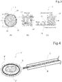
- a device 1' includes a support 2' for supporting the sheet-shaped object S and a protective member 4' having a low coefficient of friction for protecting one surface of the support 2'.
- the support 2' is molded so as to have an uneven surface, and can exhibit a frictional force for preventing the sheet-shaped object S from being displaced in the horizontal direction with respect to the support 2'.
- a contact area between the support 2' and the sheet-shaped object S is small due to the uneven shape, and therefore the sheet-shaped object S can be easily detached from the support 2'.
- the support 2' and the protective member 4' each have a circular shape. That is, the sheet-shaped object S (sheet-shaped cell culture) generally has a circular shape, and therefore can be appropriately protected by the support 2'.
- the protective member 4' does not have an unnecessary area, and therefore friction of the protective member 4' can be minimized when the protective member 4' slides on an inner surface of the tubular body 5.
- by forming each of the support 2' and the protective member 4' in a circular shape, as described above simply by bringing a circular top (protruding portion) into contact with an opening of the tubular body 5 and pressing the top against the opening, the device 1' can be easily bent and pushed into the tubular body 5.
- the sheet-shaped object S When the sheet-shaped object S is attached to a target site A (not illustrated), first, the sheet-shaped cell culture (laminate) is placed on the support 2' such that an extracellular matrix side faces up. A surface of the support 2' on the opposite side to the side on which the sheet-shaped object S is placed is covered with the protective member 4'. The device 1' is rolled such that the sheet-shaped object S is inside. Two points where no sheet-shaped object S is present (for example, both ends of the support 2' or both ends of the protective member 4') are overlapped with each other. Next, the overlapping portion is pressed (gripped) by the forceps 6 and inserted into the tubular body 5 (for example, a laparoscopic port).
- the overlapping portion is pressed (gripped) by the forceps 6 and inserted into the tubular body 5 (for example, a laparoscopic port).
- a distal end side (tubular body 5 side) of the rolled device 1' is thin like a distal end of a needle (due to its circular shape), and therefore the distal end side of the rolled device 1' can be easily inserted into the tubular body 5.
- the target site A for example, an organ
- the device 1' is pushed out of the tubular body 5, and pressing by the forceps 6 is released, as described above, the support 2' is developed into a plane shape due to its resilience. Therefore, the sheet-shaped object S can be appropriately delivered to the target site A without generating wrinkles and the like.
- front and back surfaces of the support 2' are inverted (turned over) such that the sheet-shaped cell culture faces the target site A side, that is, such that an extracellular matrix (ECM) side of the sheet-shaped cell culture faces the target site A side.
- ECM extracellular matrix
- the device 1' (support 2' and protective member 4') supporting the sheet-shaped object S is placed at the target site A.
- the protective member 4' and the support 2' are removed in this order using the forceps 6 (or other forceps).
- the sheet-shaped object S can be detached stepwise as described in Fig.
- the sheet-shaped object S can be detached carefully and surely while presence or absence of wrinkles and the like that may be generated on the sheet-shaped object S is checked.
- the sheet-shaped object S can be surely detached from the support 2' and attached onto the target site A.
- the sheet-shaped object S can be easily detached from the support 2'.
- the support 2' and/or the protective member 4' can also be collected in the tubular body 5.
- the support 2' and the protective member 4' each have a circular shape, and therefore can be collected in the tubular body 5 by gripping any portion of an end of the circular shape with the forceps 6. That is, any portion of the end of the circular shape grips the top of such a protruding portion as described above.
- the support 2' and the protective member 4' can be easily bent and collected. Therefore, the collection operation can be performed efficiently without precisely adjusting the orientations of the tubular body 5 and the forceps 6, positioning of the forceps 6 with respect to the support 2' and/or the protective member 4', and the like.
- a sheet-shaped object can be efficiently attached to a target site by a simple mechanism and a simple operation. Therefore, there are large advantages in terms of operability and manufacturing cost.
- the sheet-shaped object can be detached stepwise. Therefore, by detaching a part of the sheet-shaped object, positioning and attaching the part of the sheet-shaped object to a target site, and then detaching the other parts stepwise, generation of wrinkles and the like can be prevented. In particular, by detaching the sheet-shaped object with a fluid, occurrence of defects and the like can be prevented, and the sheet-shaped object can be efficiently attached while the shape of the sheet-shaped object is maintained.
- each component can be replaced with any component capable of exhibiting a similar function, or any component can be added.
- a sheet-shaped cell culture obtained by laminating a fibrin gel, the sheet-shaped cell culture, and an ECM in this order from the top was placed on a PDMS support with a plurality of holes to which a thread-like member was locked such that an ECM side faced up.
- the side opposite to the side on which the support was placed was covered with a nylon mesh protective member.
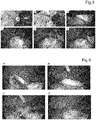
- the protected sheet-shaped cell culture was gripped with laparoscopic gripping forceps while being rolled such that the sheet-shaped cell culture was inside, and was brought close to a laparoscopic port inserted into a body cavity ( Fig. 5A ).
- the rolled and protected sheet-shaped cell culture was inserted through an opening (diameter 12 mm) of the laparoscopic port, and was caused to reach an abdominal cavity ( Fig. 5B ).
- the sheet-shaped cell culture was brought close to a target organ ( Fig. 5C ). Gripping with the gripping forceps was released, and the sheet-shaped cell culture was developed. Front and back surfaces of the support were inverted. An ECM side of the sheet-shaped cell culture was disposed on the target organ ( Fig. 5D ).
- the protective member was removed, the support was removed ( Fig. 5E ), and only the sheet-shaped cell culture was attached to the target organ ( Fig. 5F ).
- the sheet-shaped cell culture By pulling the thread-like member stepwise when the support was removed, the sheet-shaped cell culture could be appropriately detached. In addition, by pulling the thread-like member, the support and the protective member could be appropriately collected. Delivery (transportation) of the sheet-shaped cell culture, attachment thereof to the target organ, and detachment of the support were each performed 10 times, and all were successful.
- Example 2 Transplantation of sheet-shaped cell culture into duodenum for porcine duodenal ESD model
- an autologous myoblast cell sheet was transplanted laparoscopically on a serosal side of the duodenum using the device, and effectiveness was evaluated.
- a sheet-shaped cell culture obtained by laminating a fibrin gel, the sheet-shaped cell culture, and an ECM in this order from the top was placed on a silicone film (support) such that an ECM side faced up.
- the side opposite to the side on which the support was placed was covered with a mesh (protective member).
- the protected sheet-shaped cell culture was rolled such that the sheet-shaped cell culture was inside.
- a portion on which the sheet-shaped cell culture was not placed was pressed by forceps, and was brought close to a laparoscopic port inserted into a body cavity. Then, the rolled and protected sheet-shaped cell culture was inserted through an opening (diameter 12 mm) of the laparoscopic port, and was caused to reach an abdominal cavity. Next, the sheet-shaped cell culture was brought close to a target site (affected portion) in the duodenum ( Fig. 6A ). Gripping with the gripping forceps was released, and the sheet-shaped cell culture was developed. Front and back surfaces of the support were inverted such that an ECM side of the sheet-shaped cell culture was bonded to the target site. Thereafter, the mesh ( Fig.
Landscapes
- Health & Medical Sciences (AREA)
- Life Sciences & Earth Sciences (AREA)
- Animal Behavior & Ethology (AREA)
- General Health & Medical Sciences (AREA)
- Veterinary Medicine (AREA)
- Engineering & Computer Science (AREA)
- Biomedical Technology (AREA)
- Heart & Thoracic Surgery (AREA)
- Public Health (AREA)
- Cardiology (AREA)
- Oral & Maxillofacial Surgery (AREA)
- Transplantation (AREA)
- Vascular Medicine (AREA)
- Surgery (AREA)
- Molecular Biology (AREA)
- Medical Informatics (AREA)
- Nuclear Medicine, Radiotherapy & Molecular Imaging (AREA)
- Materials For Medical Uses (AREA)
- Infusion, Injection, And Reservoir Apparatuses (AREA)
- Apparatus Associated With Microorganisms And Enzymes (AREA)
Abstract
Description
- The present invention relates to a device for attaching a sheet-shaped object to a target site and a method for attaching a sheet-shaped object using the device.
- In recent years, attempts have been made to transplant various cells for repairing damaged tissues and the like. For example, in order to repair myocardial tissues damaged by an ischemic heart disease such as angina or myocardial infarction, use of fetal cardiomyocytes, myoblast cells, mesenchymal stem cells, cardiac stem cells, ES cells, iPS cells, and the like has been attempted (Non Patent Literature 1).
- As a part of such an attempt, a cell structure formed by using a scaffold and a sheet-shaped cell culture in which cells are formed in a sheet shape have been developed (Non Patent Literature 2).
- Regarding a therapeutic application of the sheet-shaped cell culture, use of a cultured epidermis sheet for skin damage caused by burns and the like, use of a corneal epithelial sheet-shaped cell culture for corneal damage, use of an oral mucosal sheet-shaped cell culture for endoscopic resection of esophageal cancer, and the like have been studied, and some of these are in a stage of clinical application.
- Regarding a surgical method for administering the sheet-shaped cell culture to a target site, endoscopic surgery is widely used as a minimally invasive surgical method for a human body, and various instruments for delivering the sheet-shaped cell culture to the target site for administration have been proposed.
- For example, a transporting/administering instrument described in
Patent Literature 1 can transport a sheet-shaped therapeutic substance up to a transplant site by forming a seat support member into a tubular shape and storing the seat support member in an outer cylinder to reduce the degree of invasion to a human body. - A sheet attaching device described in
Patent Literature 2 detaches a rod-shaped member disposed along a surface of a sheet support portion by moving the rod-shaped member along the surface of the sheet support portion, and can attach the sheet-shaped substance to a target site. - A transporting/administering instrument described in
Patent Literature 3 can administer a sheet using a sheet attachment/detachment means capable of applying a negative pressure for attaching and holding a sheet-shaped therapeutic substance to a sheet support and a positive pressure for detaching the sheet-shaped therapeutic substance from the sheet support. - A conveyance instrument described in
Patent Literature 4 can attach a sheet-shaped therapeutic substance by ejecting a fluid from a plurality of vents formed on a surface of a head holding the sheet-shaped therapeutic substance. -
- Patent Literature 1:
JP 2009-511 A - Patent Literature 2:
JP 2016-187601 A - Patent Literature 3:
JP 2008-173333 A - Patent Literature 4:
WO 2014/069292 A -
- Non Patent Literature 1: Haraguchi et al., Stem Cells Transl Med. 2012 Feb; 1 (2): 136-41
- Non Patent Literature 2: Sawa et al., Surg Today. 2012 Jan; 42 (2): 181-4
- Under these circumstances, in developing a means for efficiently attaching a sheet-shaped object to a target site, the present inventors faced a problem that it is difficult to efficiently and quickly detach a sheet-shaped object from a device without causing damage or generating wrinkles. Therefore, an object of the present invention is to solve such a problem and to achieve a rational device having a simple configuration and.
- In making intensive studies in order to solve the above problem, the present inventors have found for the first time that a sheet-shaped object can be efficiently attached to a target site while maintaining the shape of the sheet-shaped object by detaching the sheet-shaped object stepwise. As a result of further continuing studies based on such findings, the present inventors have completed the present invention.
- That is, the present invention relates to the following.
- [1] A sheet-shaped object attaching device including a support (a support body) for supporting a sheet-shaped object and a thread-like member engaged with (locked to) the support, in which the device can collect the support by discharging the sheet-shaped object supported by the support near a target site in a body cavity and pulling the thread-like member.
- [2] The device according to [1], in which the support has at least one hole.
- [3] The device according to [1] or [2], further including a protective member having a low coefficient of friction for protecting one surface of the support.
- [4] The device according to [3], further including a thread-like member engaged with the protective member.
- [5] A method for attaching a sheet-shaped object to a target site, the method including: a step of delivering a sheet-shaped object attaching device including a support for supporting a sheet-shaped object and a thread-like member engaged with the support to a target site; and a step of detaching the sheet-shaped object from the support and attaching the sheet-shaped object to the target site.
- [6] The method according to [5], in which the support has a plurality of holes, and the sheet-shaped object is detached from the support by discharging a fluid from the plurality of holes while moving a discharge position.
- [7] The method according to [5] or [6], in which the sheet-shaped object is detached from the support stepwise by pulling the thread-like member engaged with the support stepwise.
- [8] A sheet-shaped object attaching device including a support for supporting a sheet-shaped object, and a protective member having a low coefficient of friction for protecting one surface of the support, in which the support supporting the sheet-shaped object is rolled while being protected by the protective member and can be inserted into a tubular body.
- [9] The device according to [8], in which the support has an uneven structure on a surface supporting the sheet-shaped object.
- [10] The device according to [8] or [9], in which the support has at least one hole.
- [11] The device according to any one of [8] to [10], in which the sheet-shaped object, the support, and the protective member each have a circular shape.
- [12] A method for attaching a sheet-shaped object to a target site, the method including: a step of rolling a support supporting a sheet-shaped object while the support is protected by a protective member, gripping the support with forceps, and inserting the support into a tubular body; a step of delivering a sheet-shaped object attaching device to a target site via the tubular body; and a step of developing the support, detaching the sheet-shaped object from the support, and attaching the sheet-shaped object to the target site.
- [13] The method according to [12], in which gripping with the forceps is performed on a portion where two points where no sheet-shaped object is present are overlapped with each other.
- [14] The method according to [12] or [13], in which the support is developed by releasing gripping with the forceps.
- [15] The method according to any one of [12] to [14], in which the development of the support includes inverting front and back surfaces of the support.
- [16] The method according to any one of [12] to [15], in which the sheet-shaped object is detached from the support stepwise by pulling an end of the support stepwise with the forceps.
- [17] The method according to any one of [12] to [16], in which the support has a plurality of holes, and the sheet-shaped object is detached from the support by discharging a fluid from the plurality of holes while moving a discharge position.
- [18] The method according to any one of [12] to [17], which is performed for transperitoneally inserting the sheet-shaped object into a body cavity via the tubular body and attaching the sheet-shaped object to the target site.
- [19] The method according to any one of [12] to [18], in which the target site is an organ, the sheet-shaped object is a sheet-shaped cell culture for promoting wound healing of the organ, and the sheet-shaped cell culture is attached to the target site such that an extracellular matrix side of the sheet-shaped cell culture is on an organ side.
- According to the device of the present invention, a sheet-shaped object can be efficiently attached to a target site by a simple mechanism and a simple operation. Therefore, there are large advantages in terms of operability and manufacturing cost.
- In addition, the sheet-shaped object can be detached stepwise. Therefore, by detaching a part of the sheet-shaped object, positioning and attaching the part of the sheet-shaped object to a target site, and then detaching the other parts stepwise, generation of wrinkles and the like can be prevented. In particular, by detaching the sheet-shaped object with a fluid, occurrence of defects and the like can be prevented, and the sheet-shaped object can be efficiently attached while the shape of the sheet-shaped object is maintained.
-
-
Fig. 1 is a conceptual diagram of adevice 1 according to a first embodiment. -
Fig. 2 is a conceptual diagram of a usage example of thedevice 1 ofFig. 1 . -
Fig. 3 is a conceptual diagram illustrating one embodiment of asupport 2. -
Fig. 4 is a conceptual diagram of a device 1' according to a second embodiment. -
Fig. 5 illustrates Example 1 using a device of the present invention. -
Fig. 6 illustrates Example 2 using the device of the present invention. -
Fig. 7 illustrates that postoperative perforation/peritonitis has not occurred three days after transplantation. -
Fig. 8 illustrates macroscopic and histological evaluation of a site to which a sheet-shaped cell culture is attached. - A "sheet-shaped object" in the present invention refers to a sheet-shaped object that has low physical strength and may be torn, broken, deformed, or the like, for example, by being detached from a device. Such a sheet-shaped object is not particularly limited, but examples thereof include a sheet-shaped structure, for example, a flat membrane-like membrane tissue made of a biological material such as a sheet-shaped cell culture, and films made of various materials such as plastic, paper, woven fabric, non-woven fabric, metal, polymer, and lipid. The sheet-shaped structure may be polygonal, circular, or the like, and the width, thickness, diameter, and the like of the sheet-shaped structure may be uniform or non-uniform. As the sheet-shaped structure in the present invention, only one sheet may be used in a single layer state, or two or more sheets may be overlapped with each other to be used in a state of a laminate. In the latter case, the layers of the laminate may be connected to each other, or do not have to be connected to each other. When the layers of the laminate are connected to each other, all overlapping portions may be connected, or overlapping portions may be partially connected.
- In the present invention, the "sheet-shaped cell culture" refers to an object obtained by connecting cells to each other to form a sheet. The cells may be connected to each other directly (including a case where cells are connected to each other via a cell element such as an adhesion molecule) and/or via an intervening substance. The intervening substance is not particularly limited as long as being a substance capable of connecting cells to each other at least physically (mechanically), but examples thereof include an extracellular matrix. The intervening substance is preferably derived from cells, and particularly preferably derived from cells constituting a cell culture. The cells are connected to each other at least physically (mechanically), but may be connected to each other more functionally, for example, chemically or electrically. The sheet-shaped cell culture may be constituted by one cell layer (single layer) or two or more cell layers (laminated (multilayer) body, for example, two layers, three layers, four layers, five layers, or six layers). The sheet-shaped cell culture may have a three-dimensional structure having a thickness exceeding the thickness of one cell without a clear layered structure of cells. For example, in a vertical cross section of the sheet-shaped cell culture, cells may be present in a non-uniform (for example, mosaic-like) arrangement without being uniformly aligned in the horizontal direction.
- The sheet-shaped cell culture preferably contains no scaffold (support). The scaffold may be used in the present technical field in order to attach cells to a surface thereof and/or an inside thereof and maintain physical integrity of the sheet-shaped cell culture. For example, a polyvinylidene fluoride (PVDF) membrane is known. The sheet-shaped cell culture of the present invention can maintain physical integrity thereof even without such a scaffold. In addition, the sheet-shaped cell culture of the present invention preferably contains only a substance derived from cells constituting the sheet-shaped cell culture, and contains no other substance.
- The cells constituting the sheet-shaped cell culture are not particularly limited as long as being able to form the sheet-shaped cell culture, and include, for example, an adherent cell (adhesive cell). The adherent cell includes, for example, an adherent somatic cell (for example, a cardiomyocyte, a fibroblast cell, an epithelial cell, an endothelial cell, a hepatocyte, a pancreatic cell, a kidney cell (a renal cell), an adrenal cell, a periodontal membrane cell, a gingival cell, a bone membrane cell, a skin cell, a synovial cell, or a chondrocyte) and a stem cell (for example, a tissue stem cell such as a myoblast or a cardiac stem cell, an embryonic stem cell, a pluripotent stem cell such as an induced pluripotent stem (iPS) cell, or a mesenchymal stem cell). The somatic cell may be a stem cell, particularly a cell differentiated from an iPS cell (iPS cell-derived adherent cell). Non-limiting examples of the cells constituting the sheet-shaped cell culture include a myoblast (for example, a myoblast cell), a mesenchymal stem cell (for example, those derived from bone marrow, an adipose tissue, peripheral blood, skin, a hair root, a muscle tissue, an endometrial membrane, placenta, and umbilical cord blood), a cardiomyocyte, a fibroblast cell, a heart stem cell, an embryonic stem cell, an iPS cell, a synovial cell, a chondrocyte, an epithelial cell (for example, an oral mucosal epithelial cell, a retinal pigment epithelial cell, or a nasal mucosal epithelial cell), an endothelial cell (for example, a vascular endothelial cell), a hepatocyte (for example, a hepatic parenchymal cell), a pancreatic cell (for example, a pancreatic islet cell), a renal cell (a kidney cell), an adrenal cell, a periodontal membrane cell, a gingival cell, a bone membrane cell, and a skin cell. Non-limiting examples of the iPS cell-derived adherent cell include a cardiomyocyte, a fibroblast cell, an epithelial cell, an endothelial cell, a hepatocyte, a pancreatic cell, a renal cell, an adrenal cell, a periodontal membrane cell, a gingival cell, a bone membrane cell, a skin cell, a synovial cell, a chondrocyte, derived from an iPS cell.
- In the present invention, the "thread-like member" is not particularly limited as long as being a linear object that does not excessively damage the sheet-shaped object when being engaged with the support, and for example, any known thread or a small diameter wire rod can be used. The thread-like member may be made of a natural material (for example, silk, cotton, or metal) or a synthetic material (for example, nylon, polyester, polypropylene, or carbon fibers), and may be soft or rigid. Locking the thread-like member to the support means a state in which the thread-like member is connected to the support and can be pulled, which can be achieved, for example, by causing the thread-like member to pass through the support, or engaging the thread-like member with the support.
- In the present invention, the "support" refers to a plate-like body having a flat surface capable of supporting a sheet-shaped object while maintaining the shape thereof. The support has flexibility and moderate softness, can be bent while supporting the sheet-shaped object, can be stored, for example, along an inside of a tubular body, and can be developed into a plane shape due to its resilience when being exposed from the tubular body. A material of the support is not particularly limited, and various known materials can be used singly or in combination of two or more kinds thereof. Examples of such a material include metal, a soft vinyl chloride resin, a polyurethane resin, a silicone rubber, a natural rubber, a synthetic rubber, a styrene-ethylene-butylene-styrene copolymer (SEBS), a styrene-ethylene-propylene-styrene copolymer (SEPS), an ethylene vinyl acetate copolymer (EVA), a polyamide resin such as nylon and a polyamide elastomer, a polyester resin such as polyethylene terephthalate (PET) and a polyester elastomer, an olefin-based resin such as polyethylene, a fluororubber, and a fluororesin. These can be used singly or in combination of two or more kinds thereof.
- In the present invention, the "plurality of holes" means two or more through holes formed in the support. By sending a fluid from the opposite surface of the support to a surface supporting the sheet-shaped object, and discharging a fluid through the holes, the sheet-shaped object can be detached from the support surface and attached. The holes only need to be able to discharge the fluid, and it is only required to form at least one hole in the support.
- The plurality of holes is preferably displaced discretely on the sheet support surface of the support such that a detachment position of the sheet-shaped object can be adjusted. For example, by forming at least one of the plurality of holes in the vicinity of an edge of the support, the sheet-shaped object can be detached from the vicinity of the edge. The arrangement of the plurality of holes can be a row × column matrix arrangement such as 2 × 2 to 40 × 40 or 5 × 5 to 20 × 20. A distance between the holes can be, for example, 0.05 mm to 10 mm or 0.5 mm to 2 mm. The diameter of each of the holes can be, for example, 0.05 mm to 10 mm or 0.3 to 0.6 mm. However, a person skilled in the art can freely select the arrangement, the distance, and the diameter without limitation to these according to the size of the sheet-shaped object, the degree of adhesion between the sheet-shaped object and the support, and the like. By making the structure of the support a mesh structure, a matrix arrangement of the plurality of holes can also be achieved.
- In the present invention, the "fluid" refers to a general term for a gas and a liquid that can extrude and detach the sheet-shaped object without damaging the sheet-shaped object. The liquid is constituted by at least one kind of component, and the component is not particularly limited, but examples thereof include a liquid such as water, an aqueous solution, a non-aqueous solution, a suspension, or an emulsion. The component constituting the liquid is not particularly limited as long as having little effect on the sheet-shaped object. When the sheet-shaped object is a membrane made of a biological material, the component constituting the liquid is preferably a biocompatible substance, that is, a substance that does not cause an undesired effect such as an inflammatory reaction, an immune reaction, or a toxic reaction on living tissues and cells, or at least a substance that slightly causes such an effect.
- In the present invention, the "target site" means a portion to which the sheet-shaped object is applied (attached). Examples of the target site include a site of damage (wound) in a luminal organ and the opposite side of a luminal wall corresponding to the site of damage. The "luminal organ" means an organ having a lumen housed in a body cavity, that is, an organ having a tubular or bag-like structure. Examples thereof include an organ of a gastrointestinal system, an organ of a circulatory system, an organ of a urethral system, an organ of a respiratory system, and an organ of a female reproductive system. The luminal organ is typically an organ of a gastrointestinal system. The "luminal wall" means an organ wall constituting a tube or a bag of a luminal organ. The luminal wall has an inner portion facing a lumen and an outer portion forming an outer surface of an organ. "One side of the luminal wall" means either the inside or the outside of the luminal wall. The outside with respect to the inside or the inside with respect to the outside is referred to as the "opposite side". A region located on the opposite side of the luminal wall with respect to a certain region on one side is referred to as "corresponding opposite side".
- In an embodiment, in a luminal tissue with damage on at least one side of a luminal wall, by transplanting a sheet-shaped cell culture to the opposite side corresponding to a site of damage, healing of the tissue can be promoted. In particular, this is effective even against damage formed by a medical treatment such as endoscopic submucosal dissection (hereinafter referred to as ESD). Therefore, a complication caused after the medical treatment can be prevented, and prognosis can be improved.
- In the present invention, "selecting a discharge position" means selecting a hole from which a fluid is discharged from among the plurality of holes. Such a selection can be performed, for example, by controlling opening and closing of the plurality of holes, and discharging a fluid while a hole at a selected specific position is opened and the other holes are closed, or discharging the fluid while a positional relationship between a position to which the fluid is delivered and the plurality of holes is changed.
- In the present invention, "the sheet-shaped object is detached stepwise" means that the sheet-shaped object is detached partially and stepwise (in a stepwise fashion). For example, by partially detaching a part (edge or the like) of the sheet-shaped object, attaching the part to a target site, and then pulling the device, the sheet-shaped object can be detached while wrinkles and the like that may be generated on the sheet-shaped object are extended. In addition, by detaching the remaining part stepwise in addition to the detached part, the sheet-shaped object can be detached carefully and surely while presence or absence of wrinkles and the like that may be generated on the sheet-shaped object is checked.
- By selecting a discharge position with a surface supporting the sheet-shaped object spatially separated from a target site to which the sheet-shaped object is applied, and detaching the sheet-shaped object from the support stepwise, the sheet-shaped object can be disposed while a part (edge or the like) of the sheet-shaped object is partially in contact with the target site (sheet-shaped object application site). Then, by detaching the remaining part of the sheet-shaped object stepwise, the sheet-shaped object can be disposed carefully and surely at the target site while the device is not in contact with the target site. Therefore, it is possible to prevent a disadvantage that the target site is damaged carelessly, for example.
- In the present invention, the "tubular body" refers to a long pipe-shaped object having a space inside. The tubular body has openings at both ends thereof, and can deliver a fluid, the support, the thread-like member, and the like to a distal end side of the tubular body through the openings and the internal space. The tubular body is not particularly limited as long as the fluid does not leak from the tubular body, and any tubular body including a commercially available tubular body can be used. Examples of a material of the tubular body include polyethylene, polypropylene, Teflon (registered trademark), polyethylene terephthalate, polymethyl methacrylate,
nylon - The tubular body may be made of a flexible material.
In this case, even when a passage for insertion into a body during laparoscopic surgery, thoracoscopic surgery, or the like is bent, the tubular body can be bent according to the form of the passage, or can be bent in order to adjust a relative angle between the tubular body and a target site. The outer diameter of the tubular body is not particularly limited, but may be, for example, 2.2 to 25 mm, and preferably 5 to 15 mm. The inner diameter of the tubular body is not particularly limited, but may be, for example, 2 to 20 mm, and preferably 3 to 15 mm. - In an embodiment, the sheet-shaped cell culture of the present invention may be very fragile and difficult to handle. Therefore, the sheet-shaped cell culture of the present invention may further have a reinforcing layer for the purpose of facilitating handling and reducing a risk of breakage. The reinforcing layer may be any layer as long as being able to reinforce the structure without impairing the function of the sheet-shaped cell culture of the present disclosure, and may be, for example, a reinforcing layer containing a gel and/or a polymer. However, the reinforcing layer is to be transplanted into a living body, and therefore is preferably a biocompatible reinforcing layer containing, for example, a biocompatible gel or polymer.
- The gel that can be used for the reinforcing layer of the present disclosure, preferably a biocompatible gel, may be any gel as long as not adversely affecting a living body when the gel is introduced into the living body. Examples thereof include a fibrin gel, a fibrinogen gel, a gelatin gel, and a collagen, without being limited thereto.
- The polymer that can be used for the reinforcing layer of the present disclosure, preferably a biocompatible polymer, may be any polymer as long as not adversely affecting a living body when the polymer is introduced into the living body. Examples thereof include polylactic acid, polyglycolic acid, polydioxano, polyglycapro, and collagen, without being limited thereto.
- As a method for forming the reinforcing layer containing a biocompatible gel, a method known in the present technical field can be used. Examples of such a method include a method for spraying a biocompatible gel or polymer, or a component as a material thereof onto a sheet-shaped cell culture, a method for laminating a sol-like biocompatible substance on a sheet-shaped cell culture and gelling the sol-like biocompatible substance, a method for soaking a sheet-shaped cell culture in a liquid gel and then solidifying the gel, and a method described in
JP 2016-52271 A - In one embodiment, the sheet-shaped cell culture of the present invention includes an extracellular matrix (ECM).
- In the present invention, the extracellular matrix produced by cells constituting the sheet-shaped cell culture is formed on a culture substrate side of the sheet-shaped cell culture, for example, by seeding cells on the culture substrate, and then culturing the cells for 24 hours or more, for example, for 24 hours, 30 hours, 36 hours, 42 hours, 48 hours, 54 hours, 60 hours, 66 hours, or 72 hours, which depends on various conditions. By using a temperature-responsive substrate as the culture substrate, the sheet-shaped cell culture containing the extracellular matrix can be easily detached.
- The extracellular matrix contributes to adhesion of the sheet-shaped cell culture to a transplant site, and can simplify a step of bonding the sheet-shaped cell culture to the transplant site, such as suturing, when the sheet cell culture is transplanted. in addition, the extracellular matrix is a cell-derived component, and therefore there is no disadvantage in using the extracellular matrix for transplantation together with the sheet-shaped cell culture according to the present invention.
- In addition, by detaching the sheet-shaped cell culture in which the extracellular matrix is formed from the culture substrate, and spraying fibrin gel or the like onto the opposite side of the extracellular matrix to form such a reinforcing layer as described above, a sheet-shaped cell culture (laminate) in which the fibrin gel (reinforcing layer), the sheet-shaped cell culture, and the extracellular matrix are laminated in this order can be prepared.
- In the present invention, the "protective member" refers to a sheet-shaped member that protects the support so as to wrap around the support when the support is moved in the tubular body. The protective member is preferably made of a material having a low coefficient of friction (for example, 0.5 or less, 0.3 or less, 0.1 or less, or 0.05 or less), and this makes it possible to smoothly slide the support on an inner surface of the tubular body while the support is protected.
- Hereinafter, a device according to a preferred first embodiment of the present invention will be described in detail with reference to the drawings.
- As illustrated in
Fig. 1 , adevice 1 according to the first embodiment of the present invention includes asupport 2 for supporting a sheet-shaped object S and a thread-like member 3 (illustrated by dotted lines for convenience) engaged with thesupport 2. Thesupport 2 has amesh structure 24 in which a plurality ofholes 21 is formed in a matrix, and anedge 23 is formed so as to surround themesh structure 24. Thesupport 2 has flexibility and moderate softness, and can be bent while supporting the sheet-shaped object S and can be inserted into (stored in) atubular body 5 or the like. By molding thesupport 2 such that a part of the contour of thesupport 2 has a protruding shape, bringing a top of the protruding portion into contact with an opening of thetubular body 5, and pressing the top against the opening to bend thesupport 2, thesupport 2 can be easily pushed into thetubular body 5 or the like. When thesupport 2 is pushed (or pulled) out of thetubular body 5, thesupport 2 can be developed into a plane shape due to its resilience. - At the
edge 23 of thesupport 2, a lockingportion 22 for locking the thread-like member 3 is disposed. By pulling the thread-like member 3 engaged with thesupport 2, thesupport 2 can be moved, pulled out of thetubular body 5, or pulled into thetubular body 5. The lockingportions 22 may be disposed at a plurality of locations on theedge 23, but the plurality ofholes 21 may be used as the lockingportions 22. A plurality of the thread-like members 3 may be engaged with thesupport 2. By gripping and moving thesupport 2 withforceps 6 and the like, thesupport 2 can be pushed into thetubular body 5 or can be pushed out of thetubular body 5. In addition, by protecting one surface of thesupport 2 with aprotective member 4 having a low coefficient of friction, and disposing thesupport 2 such that theprotective member 4 slides on an inner surface of thetubular body 5, thesupport 2 can be easily inserted. That is, thedevice 1 can further include at least one of theprotective member 4, thetubular body 5, and theforceps 6. - As illustrated in
Fig. 2 , when thedevice 1 is used, thesupport 2 supporting the sheet-shaped object S is inserted into the tubular body 5 (Fig. 2A ). Next, thesupport 2 is disposed near a target site A and the sheet-shaped object S is detached (Fig. 2B ). Then, thesupport 2 is collected with the thread-like member 3 (Fig. 2C ). The sheet-shaped object S can also be detached by placing thesupport 2 supporting the sheet-shaped object S at the target site A and removing the support 2 (Fig. 2D ). - As illustrated in
Fig. 2A , the sheet-shaped object S is disposed on thesupport 2 with a sticky liquid such as water interposed between the sheet-shaped object S and thesupport 2, and thesupport 2 is bent (rolled) and inserted into (stored in) thetubular body 5. At this time, by disposing the sheet-shaped object S inside thesupport 2, the sheet-shaped object S can be protected. Instead of thetubular body 5, a port used in endoscopic surgery or the like may be used. Furthermore, by disposing thesupport 2 inside the protective member 4 (not illustrated), thesupport 2 can be easily moved in thetubular body 5 by utilizing the low coefficient of friction of theprotective member 4. In this case, by locking the thread-like member 3 to theprotective member 4, theprotective member 4 can be easily collected. As theprotective member 4, a nylon mesh having a diameter of 80 µm or the like can be used. - When the
support 2 is bent (rolled) and inserted into thetubular body 5, thesupport 2 may be inserted by rolling thesupport 2 by hand, thesupport 2 may be bent and inserted by pulling thesupport 2 with the thread-like member 3 (not illustrated), bringing thesupport 2 into contact with an opening of thetubular body 5, and pressing thesupport 2 against the opening of thetubular body 5, or thesupport 2 may be bent and inserted by gripping thesupport 2 with theforceps 6 and pressing thesupport 2 against the opening of thetubular body 5. At this time, by pressing a top of the protruding portion of thesupport 2 against thetubular body 5, thesupport 2 can be bent more easily. When theprotective member 4 is used, by molding theprotective member 4 such that a part of the contour of theprotective member 4 has a protruding shape, and pressing a top of the protruding portion against thetubular body 5, thesupport 2 can be bent together with theprotective member 4. - When the
tubular body 5 has already been inserted into a body cavity, by inserting thedevice 1 from a proximal end side of thetubular body 5 and pushing out thedevice 1 to a distal end side of thetubular body 5, thedevice 1 can be delivered into the body cavity. When a distal end side of thetubular body 5 is outside the body cavity, by inserting thedevice 1 from the distal end side of thetubular body 5 and storing thedevice 1 therein, then inserting thetubular body 5 into the body cavity, and pushing out thedevice 1 to the distal end side, thedevice 1 can be delivered into the body cavity. In the latter case, a movement distance of thedevice 1 is short, and therefore the procedure is simple. In addition, due to long distance movement of thesupport 2 within thetubular body 5, a disadvantage such as careless disengagement of thesupport 2 from theforceps 6 can be reduced. - As illustrated in
Fig. 2B , when the sheet-shaped object S is attached to the target site A, a distal end of thetubular body 5 in which thesupport 2 is stored is placed close to the target site A for positioning. At this time, by providing a certain distance between thetubular body 5 and the target site A, for example, a disadvantage that thetubular body 5 and thesupport 2 damage the target site A can be prevented. Next, thesupport 2 is gripped with theforceps 6 and the like, pushed out toward a distal end side of thetubular body 5, and thesupport 2 is developed into a plane shape. At this time, when theprotective member 4 is used, by locking the thread-like member 3 to theprotective member 4 and pulling the thread-like member 3, theprotective member 4 can be removed from thesupport 2 and can be collected in thetubular body 5. In addition, by using forceps (not illustrated) different from theforceps 6 inserted into thetubular body 5, thesupport 2 may be gripped, or theprotective member 4 may be collected. - Then, by spraying a fluid from the surface of the
support 2 opposite to the surface supporting the sheet-shaped object S, the fluid is discharged from the plurality ofholes 21 in the direction of the arrow to detach the sheet-shaped object S from thesupport 2. At this time, by moving the position onto which the fluid is sprayed (fluid discharge position) from one end of thesupport 2 to the other end thereof, the sheet-shaped object S can be detached stepwise. For example, by partially detaching a part of the sheet-shaped object S (for example, an edge), attaching the part to a target site, and detaching the remaining part stepwise, the sheet-shaped object S can be detached carefully and surely and can be attached to the target site A while presence or absence of wrinkles and the like that may be generated on the sheet-shaped object S is checked. - In
Fig. 2B , thesupport 2 holds a certain distance from the target site by being gripped with theforceps 6, but this can also be achieved by using the thread-like member 3 instead of theforceps 6. That is, by disposing a plurality of (two or more) locking portions in thesupport 2 to lock the plurality of thread-like members 3 and pulling the plurality of thread-like member 3, the detachment operation can be performed in a state where thesupport 2 is floated in the air, that is, in a state where a certain distance from the target site is maintained. For example, when there are two thread-like members 3, by pulling the two thread-like members 3 in opposite directions, thesupport 2 can be floated in the air. When there are three or more thread-like members 3, by pulling the three or more thread-like members 3 radially, thesupport 2 can be floated in the air. Therefore, at least theedge 23 of thesupport 2 preferably has enough strength to withstand a tensile stress caused by the thread-like member 3. - As illustrated in
Fig. 2C , after the sheet-shaped object S is attached to the target site A, by pulling the thread-like member 3 engaged with thesupport 2 into thetubular body 5, thesupport 2 can be collected. Also at this time, thesupport 2 is pressed against the opening of thetubular body 5, rolled, and stored therein. Therefore, the contour of thesupport 2 can also be molded such that both a side pushed into thetubular body 5 and a side pulled into thetubular body 5 have protruding shapes (for example, a circular shape as illustrated by thesupport 2 inFig. 1 ). By collecting (storing) thesupport 2 in thetubular body 5, thesupport 2 can be taken out of the body cavity simply by pulling out thetubular body 5, and for example, a disadvantage that thedeveloped support 2 damages another part in the body cavity is unlikely to occur. In addition, even when thesupport 2 falls off at the time of collection, thesupport 2 can be collected by pulling the thread-like member 3. In this way, by preferably using thedevice 1 including thesupport 2 for supporting the sheet-shaped object S and the thread-like member 3 engaged with thesupport 2 in combination with theprotective member 4, thetubular body 5, theforceps 6, and the like, the sheet-shaped object S can be efficiently attached. - As illustrated in
Fig. 2D , by placing thesupport 2 supporting the sheet-shaped object S at the target site A, that is, by attaching the sheet-shaped object S to the target site A together with thesupport 2 and pulling the thread-like member 3 engaged with thesupport 2 stepwise, thesupport 2 can be removed from the sheet-shaped object S stepwise, that is, the sheet-shaped object S can be detached (discharged) from thesupport 2 stepwise and attached to the target site A. By adjusting a direction in which the thread-like member 3 is pulled, a speed at which the thread-like member 3 is pulled, an angle at which the thread-like member 3 is pulled, and the like, thedevice 1 of the present invention can adjust a detachment (discharge) position of the sheet-shaped object S and a speed thereof, and therefore can detach the sheet-shaped object carefully and surely while presence or absence of wrinkles and the like that may be generated on the sheet-shaped object is checked. In this case, by pulling the thread-like member 3 engaged with a distal end side (left side in the drawing) of thesupport 2 to a proximal end side (right side in the drawing) of thesupport 2, and removing thesupport 2 such that a bending angle of thesupport 2 is acute, the sheet-shaped object S can be prevented from following thesupport 2. In addition, by removing thesupport 2 from the sheet-shaped object S while discharging a fluid from the plurality ofholes 21, the sheet-shaped object S can be prevented from following thesupport 2. However, since this function can be achieved by pulling the thread-like member 3, the plurality ofholes 21 of thesupport 2 can be omitted. -
Figs. 3A to 3C illustrate one embodiment of thesupport 2. As illustrated in the drawings, thesupport 2 has themesh structure 24 in which the plurality ofholes 21 is displaced in a matrix, and theedge 23 is formed so as to surround the mesh structure (Fig. 3A ). As illustrated inFig. 3B , holes 21' and 21" each have a rectangular shape of 300 µm × 1000 µm, and a distance between the holes 21' and thehole 21" is 500 µm. As illustrated inFig. 3C , the size of theedge 23 of thesupport 2 is 2 mm × 500 µm, and the size of a grid portion of themesh structure 24 of thesupport 2 is 500 µm × 500 µm. As illustrated, theedge 23 is thicker than themesh structure 24. Therefore, for example, by inserting the thread-like member 3 into thehole 21 between theedge 23 and themesh structure 24, thehole 21 can also be used as the lockingportion 22. That is, when the thread-like member 3 is inserted into thehole 21 and used as the lockingportion 22, and the thread-like member 3 is pulled in the horizontal direction of thesupport 2, the thread-like member 3 is caught by theedge 23, and therefore, for example, a disadvantage that thesupport 2 is broken is unlikely to occur. In addition, thesupport 2 has an uneven (concavity-and-convexity) surface because mesh portions of themesh structure 24 and the plurality ofholes 21 are alternately displaced, therefore can exhibit a frictional force for preventing the sheet-shaped object S from being displaced horizontally with respect to thesupport 2, has a small contact area, and therefore can be easily detached from the sheet-shaped object S. Therefore, when the plurality ofholes 21 of thesupport 2 is omitted as described above, by molding thesupport 2 so as to have an uneven surface, the frictional force can be exhibited. - As is clear from the above, the
device 1 only needs to include at least thesupport 2 for supporting the sheet-shaped object S and the thread-like member 3 engaged with thesupport 2. In addition, by placing thesupport 2 supporting the sheet-shaped object S at the target site A, and removing thesupport 2 stepwise while pulling thesupport 2 with the thread-like member 3 as described above, as described inFig. 2B , the sheet-shaped object S can be detached stepwise, that is, the sheet-shaped object can be detached carefully and surely while presence or absence of wrinkles and the like that may be generated on the sheet-shaped object is checked. Thesupport 2 can also be collected using a laparoscopic surgical excision bag (such as INZII (registered trademark)). - As described above, according to the
device 1 according to the first embodiment of the present invention, a sheet-shaped object can be efficiently attached to a target site by a simple mechanism and a simple operation. Therefore, there are large advantages in terms of operability and manufacturing cost. - In addition, the sheet-shaped object can be detached stepwise. Therefore, by detaching a part of the sheet-shaped object, positioning and attaching the part of the sheet-shaped object to a target site, and then detaching the other parts stepwise, generation of wrinkles and the like can be prevented. In particular, by detaching the sheet-shaped object with a fluid, occurrence of defects and the like can be prevented, and the sheet-shaped object can be efficiently attached while the shape of the sheet-shaped object is maintained.
- The device of the present invention can be used sequentially, for example, through the following steps.
- (1) The support on which the sheet-shaped object is disposed is brought close to a target site.
- (2) A fluid is discharged from some of the plurality of holes.
- (3) A detached portion is attached to the target site.
- (4) A discharge position is moved, and the fluid is discharged from another hole.
- (5) The detached portion is attached to the target site.
- In order to dispose the support on which the sheet-shaped object is disposed in a state of being spatially separated from the target site, the support on which the sheet-shaped object is disposed only needs to be brought close to the target site. At this time, the sheet-shaped object can be floated in the air using the thread-like member so as not to come into contact with the target site. Even after the sheet-shaped object is detached from the sheet support, the state in which the sheet-shaped object is not in contact with the target site can be maintained until the sheet-shaped object is attached to the target site. Detachment and attachment of the sheet-shaped object may be performed separately or simultaneously. In addition, after the sheet-shaped object is attached, a step of spraying a fluid onto the attached sheet-shaped object may be added. As a result, the sheet-shaped object can be more surely bonded to the target site. At this time as well, the sheet-shaped object can be bonded to the target site in a state where the sheet support is not in contact with the target site. In addition, by spraying a gel and/or a polymer as a fluid, a reinforcing layer that reinforces the sheet-shaped object may be formed.
- Hereinabove, the present invention has been described with reference to the illustrated embodiment, but the present invention is not limited thereto.
- In the present invention, each component can be replaced with any component capable of exhibiting a similar function, or any component can be added.
- For example, as described above, the
support 2 can be collected by pulling the thread-like member 3, but the thread-like member 3 can be omitted by performing such collection with theforceps 6. Hereinafter, a device of the present invention in which the thread-like member 3 is omitted will be described. - Hereinafter, a device according to a preferred second embodiment of the present invention will be described in detail with reference to the drawings. In the present embodiment, description will be made by assuming that the device does not include the thread-
like member 3 and that the sheet-shaped object S is a sheet-shaped cell culture (laminate) obtained by laminating a fibrin gel (reinforcing layer), the sheet-shaped cell culture, and an extracellular matrix in this order. - As illustrated in
Fig. 4 , a device 1' according to the second embodiment of the present invention includes a support 2' for supporting the sheet-shaped object S and a protective member 4' having a low coefficient of friction for protecting one surface of the support 2'. In the present embodiment, the support 2' is molded so as to have an uneven surface, and can exhibit a frictional force for preventing the sheet-shaped object S from being displaced in the horizontal direction with respect to the support 2'. In addition, a contact area between the support 2' and the sheet-shaped object S is small due to the uneven shape, and therefore the sheet-shaped object S can be easily detached from the support 2'. - The support 2' and the protective member 4' each have a circular shape. That is, the sheet-shaped object S (sheet-shaped cell culture) generally has a circular shape, and therefore can be appropriately protected by the support 2'. In addition, the protective member 4' does not have an unnecessary area, and therefore friction of the protective member 4' can be minimized when the protective member 4' slides on an inner surface of the
tubular body 5. In addition, by forming each of the support 2' and the protective member 4' in a circular shape, as described above, simply by bringing a circular top (protruding portion) into contact with an opening of thetubular body 5 and pressing the top against the opening, the device 1' can be easily bent and pushed into thetubular body 5. - When the sheet-shaped object S is attached to a target site A (not illustrated), first, the sheet-shaped cell culture (laminate) is placed on the support 2' such that an extracellular matrix side faces up. A surface of the support 2' on the opposite side to the side on which the sheet-shaped object S is placed is covered with the protective member 4'. The device 1' is rolled such that the sheet-shaped object S is inside. Two points where no sheet-shaped object S is present (for example, both ends of the support 2' or both ends of the protective member 4') are overlapped with each other. Next, the overlapping portion is pressed (gripped) by the
forceps 6 and inserted into the tubular body 5 (for example, a laparoscopic port). At this time, a distal end side (tubular body 5 side) of the rolled device 1' is thin like a distal end of a needle (due to its circular shape), and therefore the distal end side of the rolled device 1' can be easily inserted into thetubular body 5. When thetubular body 5 is moved to the target site A (for example, an organ), the device 1' is pushed out of thetubular body 5, and pressing by theforceps 6 is released, as described above, the support 2' is developed into a plane shape due to its resilience. Therefore, the sheet-shaped object S can be appropriately delivered to the target site A without generating wrinkles and the like. - Next, front and back surfaces of the support 2' are inverted (turned over) such that the sheet-shaped cell culture faces the target site A side, that is, such that an extracellular matrix (ECM) side of the sheet-shaped cell culture faces the target site A side. The device 1' (support 2' and protective member 4') supporting the sheet-shaped object S is placed at the target site A. Then, the protective member 4' and the support 2' are removed in this order using the forceps 6 (or other forceps). At this time, by gripping an end of the support 2' with the
forceps 6 and pulling the end stepwise, the sheet-shaped object S can be detached stepwise as described inFig. 2D , that is, the sheet-shaped object S can be detached carefully and surely while presence or absence of wrinkles and the like that may be generated on the sheet-shaped object S is checked. In addition, at this time, by discharging a fluid from a plurality of holes while moving a discharge position, the sheet-shaped object S can be surely detached from the support 2' and attached onto the target site A. - In addition, due to the uneven shape of the support 2', the sheet-shaped object S can be easily detached from the support 2'.
- The support 2' and/or the protective member 4' can also be collected in the
tubular body 5. At this time, the support 2' and the protective member 4' each have a circular shape, and therefore can be collected in thetubular body 5 by gripping any portion of an end of the circular shape with theforceps 6. That is, any portion of the end of the circular shape grips the top of such a protruding portion as described above. By pressing this top against thetubular body 5, the support 2' and the protective member 4' can be easily bent and collected. Therefore, the collection operation can be performed efficiently without precisely adjusting the orientations of thetubular body 5 and theforceps 6, positioning of theforceps 6 with respect to the support 2' and/or the protective member 4', and the like. - As described above, according to the device 1' according to the second embodiment of the present invention, a sheet-shaped object can be efficiently attached to a target site by a simple mechanism and a simple operation. Therefore, there are large advantages in terms of operability and manufacturing cost.
- In addition, the sheet-shaped object can be detached stepwise. Therefore, by detaching a part of the sheet-shaped object, positioning and attaching the part of the sheet-shaped object to a target site, and then detaching the other parts stepwise, generation of wrinkles and the like can be prevented. In particular, by detaching the sheet-shaped object with a fluid, occurrence of defects and the like can be prevented, and the sheet-shaped object can be efficiently attached while the shape of the sheet-shaped object is maintained.
- Hereinabove, the present invention has been described with reference to the illustrated embodiment, but the present invention is not limited thereto.
- In the present invention, each component can be replaced with any component capable of exhibiting a similar function, or any component can be added.
- A sheet-shaped cell culture obtained by laminating a fibrin gel, the sheet-shaped cell culture, and an ECM in this order from the top was placed on a PDMS support with a plurality of holes to which a thread-like member was locked such that an ECM side faced up. The side opposite to the side on which the support was placed was covered with a nylon mesh protective member. The protected sheet-shaped cell culture was gripped with laparoscopic gripping forceps while being rolled such that the sheet-shaped cell culture was inside, and was brought close to a laparoscopic port inserted into a body cavity (
Fig. 5A ). Then, the rolled and protected sheet-shaped cell culture was inserted through an opening (diameter 12 mm) of the laparoscopic port, and was caused to reach an abdominal cavity (Fig. 5B ). Next, the sheet-shaped cell culture was brought close to a target organ (Fig. 5C ). Gripping with the gripping forceps was released, and the sheet-shaped cell culture was developed. Front and back surfaces of the support were inverted. An ECM side of the sheet-shaped cell culture was disposed on the target organ (Fig. 5D ). Then, the protective member was removed, the support was removed (Fig. 5E ), and only the sheet-shaped cell culture was attached to the target organ (Fig. 5F ). By pulling the thread-like member stepwise when the support was removed, the sheet-shaped cell culture could be appropriately detached. In addition, by pulling the thread-like member, the support and the protective member could be appropriately collected. Delivery (transportation) of the sheet-shaped cell culture, attachment thereof to the target organ, and detachment of the support were each performed 10 times, and all were successful. - For a porcine duodenal ESD model with 100% delayed perforation after ESD, an autologous myoblast cell sheet was transplanted laparoscopically on a serosal side of the duodenum using the device, and effectiveness was evaluated. A sheet-shaped cell culture obtained by laminating a fibrin gel, the sheet-shaped cell culture, and an ECM in this order from the top was placed on a silicone film (support) such that an ECM side faced up. The side opposite to the side on which the support was placed was covered with a mesh (protective member). The protected sheet-shaped cell culture was rolled such that the sheet-shaped cell culture was inside. A portion on which the sheet-shaped cell culture was not placed was pressed by forceps, and was brought close to a laparoscopic port inserted into a body cavity. Then, the rolled and protected sheet-shaped cell culture was inserted through an opening (
diameter 12 mm) of the laparoscopic port, and was caused to reach an abdominal cavity. Next, the sheet-shaped cell culture was brought close to a target site (affected portion) in the duodenum (Fig. 6A ). Gripping with the gripping forceps was released, and the sheet-shaped cell culture was developed. Front and back surfaces of the support were inverted such that an ECM side of the sheet-shaped cell culture was bonded to the target site. Thereafter, the mesh (Fig. 6B ) was detached, and the silicone film (Fig. 6C ) was detached. Then, only the sheet-shaped cell culture was disposed (attached) onto the target site (Fig. 6D ). When the support was detached, the silicone film and the sheet-shaped cell culture could be appropriately detached using gripping forceps. Then, the protective member and the support were gripped with forceps and stored (collected) in the laparoscopic port again, and it was confirmed that only the sheet-shaped cell culture could be attached to the target site. As a result, a success ratio of transporting, attaching, and detaching the sheet-shaped cell culture with this device was 100%. In addition, it was confirmed that postoperative perforation/peritonitis had not occurred three days after cell sheet transplantation (A: not occurred, B: occurred) (*perforation was performed during ESD in one case) (Fig. 7 ). Thereafter, the specimen was extracted, and the site to which the sheet-shaped cell culture was attached was evaluated macroscopically and histologically. Proliferation of tissues at the transplant site was confirmed, and the residual sheet-shaped cell culture was confirmed (Fig. 8 : histopathological findings (duodenum)). -
- 1, 1'
- Device
- 2, 2'
- Support body
- 21, 21', 21"
- Hole
- 22
- Locking portion
- 23
- Edge
- 24
- Mesh structure
- 3
- Thread-like member
- 4, 4'
- Protective member
- 5
- Tubular body
- 6
- Forceps
- S
- Sheet-shaped object
- A
- Target site
Claims (19)
- A sheet-shaped object attaching device comprising:a support body supporting a sheet-shaped object; and a thread-like member engaged with the support body, whereinthe device can release the sheet-shaped object supported by the support body near a target site in a body cavity, and collect the support body by pulling the thread-like member.
- The device according to claim 1, wherein the support body has at least one hole.
- The device according to claim 1 or 2, further comprising a protective member having a low coefficient of friction for protecting one surface of the support.
- The device according to claim 3, further comprising a thread-like member engaged with the protective member.
- A method for attaching a sheet-shaped object to a target site, the method comprising:delivering a sheet-shaped object attaching device including a support body supporting a sheet-shaped object and a thread-like member engaged with the support body to a target site; anddetaching the sheet-shaped object from the support body and attaching the sheet-shaped object to the target site.
- The method according to claim 5, wherein the support body has a plurality of holes, and the sheet-shaped object is detached from the support body by discharging a fluid from the plurality of holes while moving a position of the dischargeing.
- The method according to claim 5 or 6, wherein the sheet-shaped object is detached from the support body in a stepwise fashion by pulling the thread-like member engaged with the support in a stepwise fashion.
- A sheet-shaped object attaching device comprising:a support body supporting a sheet-shaped object; and a protective member having a low coefficient of friction for protecting one surface of the support, whereinthe support body supporting the sheet-shaped object is rolled while being protected by the protective member and can be inserted into a tubular body.
- The device according to claim 8, wherein the support body has an uneven structure on a surface supporting the sheet-shaped object.
- The device according to claim 8 or 9, wherein the support body has at least one hole.
- The device according to any one of claims 8 to 10, wherein the sheet-shaped object, the support body, and the protective member each have a circular shape.
- A method for attaching a sheet-shaped object to a target site, the method comprising:rolling a support body supporting a sheet-shaped object while the support body is protected by a protective member, gripping the support body with forceps, and inserting the support body into a tubular body;delivering a sheet-shaped object attaching device to a target site via the tubular body; anddeveloping the support body, detaching the sheet-shaped object from the support body, and attaching the sheet-shaped object to the target site.
- The method according to claim 12, wherein gripping with the forceps is performed on a portion where two points where no sheet-shaped object is present are overlapped with each other.
- The method according to claim 12 or 13, wherein the support body is developed by releasing gripping with the forceps.
- The method according to any one of claims 12 to 14, wherein the development of the support includes inverting front and back surfaces of the support.
- The method according to any one of claims 12 to 15, wherein the sheet-shaped object is detached from the support body in a stepwise fashion by pulling an end of the support body in a stepwise fashion with the forceps.
- The method according to any one of claims 12 to 16, wherein the support body has a plurality of holes, and the sheet-shaped object is detached from the support body by discharging a fluid from the plurality of holes while moving a discharge position.
- The method according to any one of claims 12 to 17, which is performed for transperitoneally inserting the sheet-shaped object into a body cavity via the tubular body and attaching the sheet-shaped object to the target site.
- The method according to any one of claims 12 to 18, wherein the target site is an organ, the sheet-shaped object is a sheet-shaped cell culture for promoting wound healing of the organ, and the sheet-shaped cell culture is attached to the target site such that an extracellular matrix side of the sheet-shaped cell culture is on an organ side.
Applications Claiming Priority (2)
| Application Number | Priority Date | Filing Date | Title |
|---|---|---|---|
| JP2018242375 | 2018-12-26 | ||
| PCT/JP2019/051069 WO2020138261A1 (en) | 2018-12-26 | 2019-12-26 | Sheet-shaped object attaching device |
Publications (2)
| Publication Number | Publication Date |
|---|---|
| EP3895754A1 true EP3895754A1 (en) | 2021-10-20 |
| EP3895754A4 EP3895754A4 (en) | 2022-05-11 |
Family
ID=71127732
Family Applications (1)
| Application Number | Title | Priority Date | Filing Date |
|---|---|---|---|
| EP19904565.9A Withdrawn EP3895754A4 (en) | 2018-12-26 | 2019-12-26 | FIXING DEVICE FOR LEAF-SHAPED OBJECT |
Country Status (6)
| Country | Link |
|---|---|
| US (1) | US20210307890A1 (en) |
| EP (1) | EP3895754A4 (en) |
| JP (1) | JP7376510B2 (en) |
| CN (1) | CN113226431A (en) |
| SG (1) | SG11202104566RA (en) |
| WO (1) | WO2020138261A1 (en) |
Cited By (1)
| Publication number | Priority date | Publication date | Assignee | Title |
|---|---|---|---|---|
| EP4086339A4 (en) * | 2020-01-24 | 2023-05-31 | Nagasaki University | BIO-ADHESIVE STRATIFORM MATERIAL FOR ADHERENCE TO AN ORGAN SURFACE |
Families Citing this family (3)
| Publication number | Priority date | Publication date | Assignee | Title |
|---|---|---|---|---|
| WO2020059854A1 (en) * | 2018-09-20 | 2020-03-26 | 国立大学法人 長崎大学 | Sheet-like material attaching device |
| WO2023120224A1 (en) * | 2021-12-22 | 2023-06-29 | テルモ株式会社 | Medical device and method for applying sheet-shaped delivery article |
| JP7836739B2 (en) * | 2022-08-30 | 2026-03-27 | テルモ株式会社 | Medical material and transfer equipment set |
Family Cites Families (17)
| Publication number | Priority date | Publication date | Assignee | Title |
|---|---|---|---|---|
| US4917089A (en) * | 1988-08-29 | 1990-04-17 | Sideris Eleftherios B | Buttoned device for the transvenous occlusion of intracardiac defects |
| CA2090000A1 (en) * | 1992-02-24 | 1993-08-25 | H. Jonathan Tovey | Articulating mesh deployment apparatus |
| US5957939A (en) * | 1997-07-31 | 1999-09-28 | Imagyn Medical Technologies, Inc. | Medical device for deploying surgical fabrics |
| JP4869736B2 (en) * | 2006-03-01 | 2012-02-08 | オリンパス株式会社 | Cell sheet mounting method and mounting device |
| US20080215089A1 (en) * | 2006-09-21 | 2008-09-04 | Williams Michael S | Stomach wall closure devices |
| JP4569971B2 (en) | 2007-01-19 | 2010-10-27 | Hoya株式会社 | Equipment for transporting and administering therapeutic substances |
| JP5219610B2 (en) * | 2007-05-22 | 2013-06-26 | Hoya株式会社 | Equipment for transporting and administering therapeutic substances |
| US7985197B2 (en) * | 2007-05-22 | 2011-07-26 | Hoya Corporation | Therapeutic-substance carrying/administering appliance |
| US20090156997A1 (en) * | 2007-12-12 | 2009-06-18 | Rockford Orthopaedic Sports Medicine Services, Llc | Rotator cuff patch delivery device |
| EP2247245B1 (en) * | 2008-02-18 | 2017-06-28 | Covidien LP | A device for deploying and attaching a patch to a biological tissue |
| US8529434B2 (en) * | 2008-10-29 | 2013-09-10 | Cook Medical Technologies Llc | Endoscopic sheet delivery |
| EP2292147B1 (en) * | 2009-09-07 | 2012-11-07 | Aeeg Ab | Device and kit for closure of a body lumen puncture |
| JP2012029909A (en) * | 2010-07-30 | 2012-02-16 | Terumo Corp | Instrument for implantation |
| US9919139B2 (en) | 2012-10-31 | 2018-03-20 | Tokyo Women's Medical University | Sheet shaped therapeutic substance transfer apparatus and method of affixing sheet shaped therapeutic substance |
| JP6495603B2 (en) | 2014-09-03 | 2019-04-03 | テルモ株式会社 | Method for producing laminate of sheet-shaped cell culture and fibrin gel |
| EP3298996B1 (en) * | 2015-05-20 | 2023-04-26 | Nichiban Company Limited | Adhesive skin patch material, and support for adhesive skin patch material which can be used in same |
| JP6253722B2 (en) | 2016-07-06 | 2017-12-27 | オリンパス株式会社 | Sheet pasting device |
-
2019
- 2019-12-26 CN CN201980086355.8A patent/CN113226431A/en active Pending
- 2019-12-26 JP JP2020562392A patent/JP7376510B2/en active Active
- 2019-12-26 WO PCT/JP2019/051069 patent/WO2020138261A1/en not_active Ceased
- 2019-12-26 SG SG11202104566RA patent/SG11202104566RA/en unknown
- 2019-12-26 EP EP19904565.9A patent/EP3895754A4/en not_active Withdrawn
-
2021
- 2021-06-18 US US17/351,295 patent/US20210307890A1/en not_active Abandoned
Cited By (1)
| Publication number | Priority date | Publication date | Assignee | Title |
|---|---|---|---|---|
| EP4086339A4 (en) * | 2020-01-24 | 2023-05-31 | Nagasaki University | BIO-ADHESIVE STRATIFORM MATERIAL FOR ADHERENCE TO AN ORGAN SURFACE |
Also Published As
| Publication number | Publication date |
|---|---|
| US20210307890A1 (en) | 2021-10-07 |
| JP7376510B2 (en) | 2023-11-08 |
| CN113226431A (en) | 2021-08-06 |
| WO2020138261A1 (en) | 2020-07-02 |
| JPWO2020138261A1 (en) | 2021-11-04 |
| EP3895754A4 (en) | 2022-05-11 |
| SG11202104566RA (en) | 2021-07-29 |
Similar Documents
| Publication | Publication Date | Title |
|---|---|---|
| US20210307890A1 (en) | Sheet-shaped object attaching device | |
| JP4569971B2 (en) | Equipment for transporting and administering therapeutic substances | |
| JP2022130211A (en) | Medical apparatus and metho for applying graft | |
| JP7531424B2 (en) | Medical device for forming implants into desired shapes | |
| JP2022055090A (en) | Medical device having curved shape for transferring implant piece | |
| JP7781881B2 (en) | Medical device for delivering sheet-shaped delivery material to a target site | |
| US20240315824A1 (en) | Medical device and method for applying sheet-shaped delivery object | |
| JP7190490B2 (en) | Sheet sticking device | |
| JP2022055088A (en) | Medical device for transferring plural implant pieces and transferring method of implant piece | |
| JP7661356B2 (en) | Apparatus for freezing and transferring a graft and method for freezing and transferring a graft | |
| JP2022055094A (en) | Medical device for transferring plural implant pieces and transferring method of implant piece | |
| JP7704593B2 (en) | Medical device and method for delivering sheet-shaped delivery material to a target site | |
| JP2022055087A (en) | Medical device for transporting implant piece and transporting method of implant piece | |
| JP7704592B2 (en) | Medical device and method for delivering sheet-shaped delivery material to a target site | |
| EP4442306A1 (en) | Medical device and method for applying sheet-shaped delivery article | |
| JP2022055086A (en) | Medical device including deformation mechanism for transferring implant piece and transferring method of implant piece | |
| JP2022055085A (en) | Medical device including extension mechanism for transferring implant piece and transferring method of implant piece | |
| JP2022055089A (en) | Medical device capable of storing plural implant pieces | |
| JP2022055084A (en) | Machine for transferring transplant and transfer method of transplant | |
| JP2013198442A (en) | Transfer device | |
| JP2022055093A (en) | Medical device for supporting implant piece in attachable and detachable manner | |
| JP2023034853A (en) | Medical apparatus and method for delivery of medical delivery object to target portion | |
| JP2022055091A (en) | Medical apparatus for delivering implants with belt conveyor type delivery mechanism | |
| US20170224464A1 (en) | Treatment method and medical device | |
| JP2024111734A (en) | Devices and methods |
Legal Events
| Date | Code | Title | Description |
|---|---|---|---|
| STAA | Information on the status of an ep patent application or granted ep patent |
Free format text: STATUS: THE INTERNATIONAL PUBLICATION HAS BEEN MADE |
|
| PUAI | Public reference made under article 153(3) epc to a published international application that has entered the european phase |
Free format text: ORIGINAL CODE: 0009012 |
|
| STAA | Information on the status of an ep patent application or granted ep patent |
Free format text: STATUS: REQUEST FOR EXAMINATION WAS MADE |
|
| 17P | Request for examination filed |
Effective date: 20210716 |
|
| AK | Designated contracting states |
Kind code of ref document: A1 Designated state(s): AL AT BE BG CH CY CZ DE DK EE ES FI FR GB GR HR HU IE IS IT LI LT LU LV MC MK MT NL NO PL PT RO RS SE SI SK SM TR |
|
| RIC1 | Information provided on ipc code assigned before grant |
Ipc: A61B 17/28 20060101ALI20220114BHEP Ipc: A61M 31/00 20060101AFI20220114BHEP |
|
| DAV | Request for validation of the european patent (deleted) | ||
| DAX | Request for extension of the european patent (deleted) | ||
| A4 | Supplementary search report drawn up and despatched |
Effective date: 20220411 |
|
| RIC1 | Information provided on ipc code assigned before grant |
Ipc: A61B 17/28 20060101ALI20220405BHEP Ipc: A61M 31/00 20060101AFI20220405BHEP |
|
| STAA | Information on the status of an ep patent application or granted ep patent |
Free format text: STATUS: THE APPLICATION HAS BEEN WITHDRAWN |
|
| 18W | Application withdrawn |
Effective date: 20230920 |