EP3895645A1 - Ablation planning system - Google Patents
Ablation planning system Download PDFInfo
- Publication number
- EP3895645A1 EP3895645A1 EP20169279.5A EP20169279A EP3895645A1 EP 3895645 A1 EP3895645 A1 EP 3895645A1 EP 20169279 A EP20169279 A EP 20169279A EP 3895645 A1 EP3895645 A1 EP 3895645A1
- Authority
- EP
- European Patent Office
- Prior art keywords
- ablation
- planning
- segmentation
- user interface
- medical instrument
- Prior art date
- Legal status (The legal status is an assumption and is not a legal conclusion. Google has not performed a legal analysis and makes no representation as to the accuracy of the status listed.)
- Withdrawn
Links
- 238000002679 ablation Methods 0.000 title claims abstract description 172
- 230000011218 segmentation Effects 0.000 claims abstract description 119
- 238000009877 rendering Methods 0.000 claims abstract description 43
- 238000000034 method Methods 0.000 claims abstract description 37
- 210000003484 anatomy Anatomy 0.000 claims abstract description 16
- 239000000523 sample Substances 0.000 claims description 66
- 238000002595 magnetic resonance imaging Methods 0.000 claims description 24
- 238000002059 diagnostic imaging Methods 0.000 claims description 19
- 230000004044 response Effects 0.000 claims description 14
- 238000003780 insertion Methods 0.000 claims description 13
- 230000037431 insertion Effects 0.000 claims description 13
- 238000004590 computer program Methods 0.000 claims description 11
- 238000004422 calculation algorithm Methods 0.000 claims description 10
- 238000001208 nuclear magnetic resonance pulse sequence Methods 0.000 claims description 10
- 238000002604 ultrasonography Methods 0.000 claims description 7
- 238000004520 electroporation Methods 0.000 claims description 3
- 230000002427 irreversible effect Effects 0.000 claims description 3
- 238000000608 laser ablation Methods 0.000 claims description 3
- 238000002591 computed tomography Methods 0.000 claims description 2
- 238000007674 radiofrequency ablation Methods 0.000 claims description 2
- 238000012285 ultrasound imaging Methods 0.000 claims description 2
- 238000003384 imaging method Methods 0.000 description 13
- 238000012800 visualization Methods 0.000 description 11
- 210000001519 tissue Anatomy 0.000 description 9
- 230000006870 function Effects 0.000 description 8
- 238000011282 treatment Methods 0.000 description 8
- 238000010586 diagram Methods 0.000 description 6
- 206010028980 Neoplasm Diseases 0.000 description 5
- 238000012545 processing Methods 0.000 description 5
- 230000003902 lesion Effects 0.000 description 4
- 230000003287 optical effect Effects 0.000 description 4
- 230000008569 process Effects 0.000 description 3
- 238000001356 surgical procedure Methods 0.000 description 3
- 238000010317 ablation therapy Methods 0.000 description 2
- 238000013528 artificial neural network Methods 0.000 description 2
- 230000009286 beneficial effect Effects 0.000 description 2
- 230000001419 dependent effect Effects 0.000 description 2
- 230000008713 feedback mechanism Effects 0.000 description 2
- 230000000644 propagated effect Effects 0.000 description 2
- 210000002307 prostate Anatomy 0.000 description 2
- 238000011298 ablation treatment Methods 0.000 description 1
- 238000013459 approach Methods 0.000 description 1
- 238000003491 array Methods 0.000 description 1
- 230000003190 augmentative effect Effects 0.000 description 1
- 230000008901 benefit Effects 0.000 description 1
- 230000005540 biological transmission Effects 0.000 description 1
- 238000002725 brachytherapy Methods 0.000 description 1
- 238000004364 calculation method Methods 0.000 description 1
- 201000011510 cancer Diseases 0.000 description 1
- 238000004891 communication Methods 0.000 description 1
- 201000010099 disease Diseases 0.000 description 1
- 208000037265 diseases, disorders, signs and symptoms Diseases 0.000 description 1
- 230000000694 effects Effects 0.000 description 1
- 239000011521 glass Substances 0.000 description 1
- 230000003993 interaction Effects 0.000 description 1
- 230000002452 interceptive effect Effects 0.000 description 1
- 238000002697 interventional radiology Methods 0.000 description 1
- 239000004973 liquid crystal related substance Substances 0.000 description 1
- 238000004519 manufacturing process Methods 0.000 description 1
- 239000011159 matrix material Substances 0.000 description 1
- 238000005259 measurement Methods 0.000 description 1
- 230000007246 mechanism Effects 0.000 description 1
- 239000013307 optical fiber Substances 0.000 description 1
- 210000000920 organ at risk Anatomy 0.000 description 1
- 239000002245 particle Substances 0.000 description 1
- 238000012805 post-processing Methods 0.000 description 1
- 238000000275 quality assurance Methods 0.000 description 1
- 238000001959 radiotherapy Methods 0.000 description 1
- 238000012552 review Methods 0.000 description 1
- 238000010845 search algorithm Methods 0.000 description 1
- 239000007787 solid Substances 0.000 description 1
- 238000002560 therapeutic procedure Methods 0.000 description 1
- 210000003813 thumb Anatomy 0.000 description 1
- 230000000007 visual effect Effects 0.000 description 1
Images


Classifications
-
- A—HUMAN NECESSITIES
- A61—MEDICAL OR VETERINARY SCIENCE; HYGIENE
- A61B—DIAGNOSIS; SURGERY; IDENTIFICATION
- A61B34/00—Computer-aided surgery; Manipulators or robots specially adapted for use in surgery
- A61B34/10—Computer-aided planning, simulation or modelling of surgical operations
-
- A—HUMAN NECESSITIES
- A61—MEDICAL OR VETERINARY SCIENCE; HYGIENE
- A61B—DIAGNOSIS; SURGERY; IDENTIFICATION
- A61B18/00—Surgical instruments, devices or methods for transferring non-mechanical forms of energy to or from the body
- A61B18/04—Surgical instruments, devices or methods for transferring non-mechanical forms of energy to or from the body by heating
- A61B18/12—Surgical instruments, devices or methods for transferring non-mechanical forms of energy to or from the body by heating by passing a current through the tissue to be heated, e.g. high-frequency current
- A61B18/14—Probes or electrodes therefor
- A61B18/148—Probes or electrodes therefor having a short, rigid shaft for accessing the inner body transcutaneously, e.g. for neurosurgery or arthroscopy
-
- A—HUMAN NECESSITIES
- A61—MEDICAL OR VETERINARY SCIENCE; HYGIENE
- A61B—DIAGNOSIS; SURGERY; IDENTIFICATION
- A61B17/00—Surgical instruments, devices or methods
- A61B17/32—Surgical cutting instruments
- A61B17/320068—Surgical cutting instruments using mechanical vibrations, e.g. ultrasonic
- A61B2017/320069—Surgical cutting instruments using mechanical vibrations, e.g. ultrasonic for ablating tissue
-
- A—HUMAN NECESSITIES
- A61—MEDICAL OR VETERINARY SCIENCE; HYGIENE
- A61B—DIAGNOSIS; SURGERY; IDENTIFICATION
- A61B18/00—Surgical instruments, devices or methods for transferring non-mechanical forms of energy to or from the body
- A61B2018/00315—Surgical instruments, devices or methods for transferring non-mechanical forms of energy to or from the body for treatment of particular body parts
- A61B2018/00547—Prostate
-
- A—HUMAN NECESSITIES
- A61—MEDICAL OR VETERINARY SCIENCE; HYGIENE
- A61B—DIAGNOSIS; SURGERY; IDENTIFICATION
- A61B18/00—Surgical instruments, devices or methods for transferring non-mechanical forms of energy to or from the body
- A61B2018/00571—Surgical instruments, devices or methods for transferring non-mechanical forms of energy to or from the body for achieving a particular surgical effect
- A61B2018/00577—Ablation
-
- A—HUMAN NECESSITIES
- A61—MEDICAL OR VETERINARY SCIENCE; HYGIENE
- A61B—DIAGNOSIS; SURGERY; IDENTIFICATION
- A61B18/00—Surgical instruments, devices or methods for transferring non-mechanical forms of energy to or from the body
- A61B2018/00571—Surgical instruments, devices or methods for transferring non-mechanical forms of energy to or from the body for achieving a particular surgical effect
- A61B2018/00613—Irreversible electroporation
-
- A—HUMAN NECESSITIES
- A61—MEDICAL OR VETERINARY SCIENCE; HYGIENE
- A61B—DIAGNOSIS; SURGERY; IDENTIFICATION
- A61B18/00—Surgical instruments, devices or methods for transferring non-mechanical forms of energy to or from the body
- A61B18/02—Surgical instruments, devices or methods for transferring non-mechanical forms of energy to or from the body by cooling, e.g. cryogenic techniques
- A61B2018/0212—Surgical instruments, devices or methods for transferring non-mechanical forms of energy to or from the body by cooling, e.g. cryogenic techniques using an instrument inserted into a body lumen, e.g. catheter
-
- A—HUMAN NECESSITIES
- A61—MEDICAL OR VETERINARY SCIENCE; HYGIENE
- A61B—DIAGNOSIS; SURGERY; IDENTIFICATION
- A61B18/00—Surgical instruments, devices or methods for transferring non-mechanical forms of energy to or from the body
- A61B18/18—Surgical instruments, devices or methods for transferring non-mechanical forms of energy to or from the body by applying electromagnetic radiation, e.g. microwaves
- A61B18/1815—Surgical instruments, devices or methods for transferring non-mechanical forms of energy to or from the body by applying electromagnetic radiation, e.g. microwaves using microwaves
- A61B2018/1861—Surgical instruments, devices or methods for transferring non-mechanical forms of energy to or from the body by applying electromagnetic radiation, e.g. microwaves using microwaves with an instrument inserted into a body lumen or cavity, e.g. a catheter
-
- A—HUMAN NECESSITIES
- A61—MEDICAL OR VETERINARY SCIENCE; HYGIENE
- A61B—DIAGNOSIS; SURGERY; IDENTIFICATION
- A61B18/00—Surgical instruments, devices or methods for transferring non-mechanical forms of energy to or from the body
- A61B18/18—Surgical instruments, devices or methods for transferring non-mechanical forms of energy to or from the body by applying electromagnetic radiation, e.g. microwaves
- A61B18/20—Surgical instruments, devices or methods for transferring non-mechanical forms of energy to or from the body by applying electromagnetic radiation, e.g. microwaves using laser
- A61B2018/2005—Surgical instruments, devices or methods for transferring non-mechanical forms of energy to or from the body by applying electromagnetic radiation, e.g. microwaves using laser with beam delivery through an interstitially insertable device, e.g. needle
-
- A—HUMAN NECESSITIES
- A61—MEDICAL OR VETERINARY SCIENCE; HYGIENE
- A61B—DIAGNOSIS; SURGERY; IDENTIFICATION
- A61B34/00—Computer-aided surgery; Manipulators or robots specially adapted for use in surgery
- A61B34/10—Computer-aided planning, simulation or modelling of surgical operations
- A61B2034/107—Visualisation of planned trajectories or target regions
-
- A—HUMAN NECESSITIES
- A61—MEDICAL OR VETERINARY SCIENCE; HYGIENE
- A61B—DIAGNOSIS; SURGERY; IDENTIFICATION
- A61B34/00—Computer-aided surgery; Manipulators or robots specially adapted for use in surgery
- A61B34/20—Surgical navigation systems; Devices for tracking or guiding surgical instruments, e.g. for frameless stereotaxis
- A61B2034/2046—Tracking techniques
- A61B2034/2051—Electromagnetic tracking systems
-
- A—HUMAN NECESSITIES
- A61—MEDICAL OR VETERINARY SCIENCE; HYGIENE
- A61B—DIAGNOSIS; SURGERY; IDENTIFICATION
- A61B34/00—Computer-aided surgery; Manipulators or robots specially adapted for use in surgery
- A61B34/25—User interfaces for surgical systems
- A61B2034/252—User interfaces for surgical systems indicating steps of a surgical procedure
-
- A—HUMAN NECESSITIES
- A61—MEDICAL OR VETERINARY SCIENCE; HYGIENE
- A61B—DIAGNOSIS; SURGERY; IDENTIFICATION
- A61B34/00—Computer-aided surgery; Manipulators or robots specially adapted for use in surgery
- A61B34/25—User interfaces for surgical systems
- A61B2034/254—User interfaces for surgical systems being adapted depending on the stage of the surgical procedure
-
- A—HUMAN NECESSITIES
- A61—MEDICAL OR VETERINARY SCIENCE; HYGIENE
- A61B—DIAGNOSIS; SURGERY; IDENTIFICATION
- A61B90/00—Instruments, implements or accessories specially adapted for surgery or diagnosis and not covered by any of the groups A61B1/00 - A61B50/00, e.g. for luxation treatment or for protecting wound edges
- A61B90/36—Image-producing devices or illumination devices not otherwise provided for
- A61B2090/364—Correlation of different images or relation of image positions in respect to the body
- A61B2090/368—Correlation of different images or relation of image positions in respect to the body changing the image on a display according to the operator's position
-
- A—HUMAN NECESSITIES
- A61—MEDICAL OR VETERINARY SCIENCE; HYGIENE
- A61B—DIAGNOSIS; SURGERY; IDENTIFICATION
- A61B90/00—Instruments, implements or accessories specially adapted for surgery or diagnosis and not covered by any of the groups A61B1/00 - A61B50/00, e.g. for luxation treatment or for protecting wound edges
- A61B90/36—Image-producing devices or illumination devices not otherwise provided for
- A61B90/37—Surgical systems with images on a monitor during operation
- A61B2090/374—NMR or MRI
-
- A—HUMAN NECESSITIES
- A61—MEDICAL OR VETERINARY SCIENCE; HYGIENE
- A61B—DIAGNOSIS; SURGERY; IDENTIFICATION
- A61B90/00—Instruments, implements or accessories specially adapted for surgery or diagnosis and not covered by any of the groups A61B1/00 - A61B50/00, e.g. for luxation treatment or for protecting wound edges
- A61B90/36—Image-producing devices or illumination devices not otherwise provided for
- A61B90/37—Surgical systems with images on a monitor during operation
- A61B2090/376—Surgical systems with images on a monitor during operation using X-rays, e.g. fluoroscopy
-
- A—HUMAN NECESSITIES
- A61—MEDICAL OR VETERINARY SCIENCE; HYGIENE
- A61B—DIAGNOSIS; SURGERY; IDENTIFICATION
- A61B90/00—Instruments, implements or accessories specially adapted for surgery or diagnosis and not covered by any of the groups A61B1/00 - A61B50/00, e.g. for luxation treatment or for protecting wound edges
- A61B90/36—Image-producing devices or illumination devices not otherwise provided for
- A61B90/37—Surgical systems with images on a monitor during operation
- A61B2090/378—Surgical systems with images on a monitor during operation using ultrasound
Definitions
- United States patent application publication US20150320509A1 discloses a system for surgical procedure assistance.
- a first image of a patient captured prior to a surgical procedure is received.
- a treatment plan is generated based on the first image.
- the treatment plan includes information related to one or more surgical instruments.
- a second image of the patient captured after the surgical procedure has been initiated is received.
- the treatment plan is dynamically adjusted based on a pose of any of the one or more surgical instruments identified from the second image.
- a third image of the patient captured after a lesion is treated by at least one of the surgical instruments based on the adjusted treatment plan is received. Whether a further treatment to the lesion is needed is determined based on the third image.
- an updated treatment plan is dynamically generated based on the third image.
- Execution of the machine-executable instructions further causes the computational system to repeatedly receive the ablation zone from the ablation selector. Execution of the machine-executable instructions further causes the computational system to repeatedly update the remaining portion by removing the ablation zone from the remaining portion.
- This embodiment may be beneficial because it may aid in the planning of an ablation. The display of the remaining portion may aid in the selection of the proper ablation zone.
- the ablation selector is configured to receive a selection of a volume within the remaining portion. Execution of the machine-executable instructions further causes the processor to generate the ablation zone in response to receiving the selection of a volume from the ablation selector. For example, the user interface may display the possible volumes which could be ablated.
- the ablation probe is a cryo-ablation probe.
- the guidance medical imaging system is a computed tomography system.
- the guidance medical imaging system is an ultrasound imaging system.
- the guidance medical imaging system is an X-ray fluoroscope.
- the memory further stores an automated segmentation algorithm configured for generating the anatomical segmentation and/or the target zone segmentation in response to inputting the planning magnetic resonance image.
- Execution of the machine-executable instructions further causes the processor to generate the anatomical segmentation and/or the target zone segmentation by inputting the planning magnetic resonance image into the automated segmentation algorithm.
- the medical instrument further comprises a planning magnetic resonance image system configured for acquiring planning k-space data of the subject.
- the label planning on the planning magnetic resonance image is intended to indicate a particular magnetic resonance imaging system.
- planning k-space data is intended to indicate specific k-space data and the word planning is used as a label.
- the memory further comprises planning pulse sequence commands configured for controlling the magnetic resonance imaging system to acquire the planning k-space data.
- the invention provides for a method of operating a medical instrument.
- the medical instrument comprises a user interface.
- the user interface comprises a display.
- the method comprises receiving an anatomical segmentation identifying a location of an anatomical structure.
- the method further comprises receiving a target zone segmentation identifying a location of a volume at least partially within the anatomical segmentation.
- the method further comprises displaying a planning graphical user interface using the display.
- the planning graphical user interface comprises a first panel configured for rendering a cross-sectional view of the anatomical segmentation and the target zone segmentation.
- the computer readable medium may be a computer readable signal medium or a computer readable storage medium.
- a 'computer-readable storage medium' as used herein encompasses any tangible storage medium which may store instructions which are executable by a processor or computational system of a computing device.
- the computer-readable storage medium may be referred to as a computer-readable non-transitory storage medium.
- the computer-readable storage medium may also be referred to as a tangible computer readable medium.
- a computer-readable storage medium may also be able to store data which is able to be accessed by the computational system of the computing device.
- Examples of computer-readable storage media include, but are not limited to: a floppy disk, a magnetic hard disk drive, a solid state hard disk, flash memory, a USB thumb drive, Random Access Memory (RAM), Read Only Memory (ROM), an optical disk, a magneto-optical disk, and the register file of the computational system.
- Examples of optical disks include Compact Disks (CD) and Digital Versatile Disks (DVD), for example CD-ROM, CD-RW, CD-R, DVD-ROM, DVD-RW, or DVD-R disks.
- the term computer readable-storage medium also refers to various types of recording media capable of being accessed by the computer device via a network or communication link.
- 'Computer memory' or 'memory' is an example of a computer-readable storage medium.
- Computer memory is any memory which is directly accessible to a computational system.
- 'Computer storage' or 'storage' is a further example of a computer-readable storage medium.
- Computer storage is any non-volatile computer-readable storage medium. In some embodiments computer storage may also be computer memory or vice versa.
- the computer executable code may execute entirely on the user's computer, partly on the user's computer, as a stand-alone software package, partly on the user's computer and partly on a remote computer or entirely on the remote computer or server.
- the remote computer may be connected to the user's computer through any type of network, including a local area network (LAN) or a wide area network (WAN), or the connection may be made to an external computer (for example, through the Internet using an Internet Service Provider).
- These computer program instructions may be provided to a computational system of a general purpose computer, special purpose computer, or other programmable data processing apparatus to produce a machine, such that the instructions, which execute via the computational system of the computer or other programmable data processing apparatus, create means for implementing the functions/acts specified in the flowchart and/or block diagram block or blocks.
- a 'user interface' as used herein is an interface which allows a user or operator to interact with a computer or computer system.
- a 'user interface' may also be referred to as a 'human interface device.
- a user interface may provide information or data to the operator and/or receive information or data from the operator.
- a user interface may enable input from an operator to be received by the computer and may provide output to the user from the computer.
- the user interface may allow an operator to control or manipulate a computer and the interface may allow the computer indicate the effects of the operator's control or manipulation.
- the display of data or information on a display or a graphical user interface is an example of providing information to an operator.
- the receiving of data through a keyboard, mouse, trackball, touchpad, pointing stick, graphics tablet, joystick, gamepad, webcam, headset, pedals, wired glove, remote control, and accelerometer are all examples of user interface components which enable the receiving of information or data from an operator.
- a 'hardware interface' as used herein encompasses an interface which enables the computational system of a computer system to interact with and/or control an external computing device and/or apparatus.
- a hardware interface may allow a computational system to send control signals or instructions to an external computing device and/or apparatus.
- a hardware interface may also enable a computational system to exchange data with an external computing device and/or apparatus. Examples of a hardware interface include, but are not limited to: a universal serial bus, IEEE 1394 port, parallel port, IEEE 1284 port, serial port, RS-232 port, IEEE-488 port, Bluetooth connection, Wireless local area network connection, TCP/IP connection, Ethernet connection, control voltage interface, MIDI interface, analog input interface, and digital input interface.
- a 'display' or 'display device' as used herein encompasses an output device or a user interface adapted for displaying images or data.
- a display may output visual, audio, and or tactile data.
- Examples of a display include, but are not limited to: a computer monitor, a television screen, a touch screen, tactile electronic display, Braille screen, Cathode ray tube (CRT), Storage tube, Bi-stable display, Electronic paper, Vector display, Flat panel display, Vacuum fluorescent display (VF), Light-emitting diode (LED) displays, Electroluminescent display (ELD), Plasma display panels (PDP), Liquid crystal display (LCD), Organic light-emitting diode displays (OLED), a projector, and Head-mounted display.
- VF Vacuum fluorescent display
- LED Light-emitting diode
- ELD Electroluminescent display
- PDP Plasma display panels
- LCD Liquid crystal display
- OLED Organic light-emitting diode displays
- K-space data is defined herein as being the recorded measurements of radio frequency signals emitted by atomic spins using the antenna of a Magnetic resonance apparatus during a magnetic resonance imaging scan.
- Magnetic resonance data is an example of tomographic medical image data.
- Magnetic Resonance Imaging (MRI) image, MR image, or magnetic resonance imaging data is defined herein as being the reconstructed two- or three-dimensional visualization of anatomic data contained within the magnetic resonance imaging data. This visualization can be performed using a computer.
- Fig. 1 illustrates an example of a medical instrument 100.
- the medical instrument 100 is shown as comprising in this particular example a computer 102.
- the computer 102 is shown as comprising an optional hardware interface 104.
- the hardware interface 104 may for example be used to control other components of the medical instrument 100 if they are present.
- the medical instrument 100 is further shown as comprising a computational system 106.
- the computational system 106 is intended to represent one or more computational systems or devices such as processors of other computers.
- the computational system 106 may be distributed also in multiple locations.
- the medical instrument 100 is further shown as comprising a user interface 108.
- the user interface comprises a planning graphical user interface 112.
- the medical instrument 100 is further shown as comprising a memory 110.
- the memory 110 represents any memory that is accessible to the computational system 106.
- the medical instrument 100 illustrated in Fig. 1 may be a component or part of a variety of different types of systems.
- the medical instrument 100 is a workstation or a computing device which is used for planning.
- the medical instrument 100 may be integrated with an ablation probe or ablation probe system.
- the medical instrument 100 may be integrated with a magnetic resonance imaging or other medical imaging system.
- the memory 110 is further shown as containing an optional automated planning module 126.
- the automated planning module may be configured for outputting a selected ablation zone in response to inputting the remaining portion.
- the memory 128 is further shown as containing insertion instructions 128 which may be presented on an optional display for insertion instructions 148.
- the insertion instructions 128 may contain instructions on where and how far to insert an ablation probe.
- the planning graphical user interface 112 is shown as comprising a first panel 130, a second panel 132, and a third panel 134.
- the first panel is configured for rendering a cross-sectional view of the anatomical segmentation 136 and a cross-sectional view of the target zone segmentation 138.
- the first panel 130 may also be configured for displaying a cross-sectional of a medical image such as a magnetic resonance image with these two cross-sectional views of the segmentations 136, 138.
- the second panel 132 is configured for displaying a rendering of a first three-dimensional model 140.
- the first three-dimensional model 140 is a three-dimensional model of the anatomical segmentation 122 and the target zone segmentation 124.
- the second panel 132 may be useful because it may display the three-dimensional models of the segmentations 122 and 124 without any other medical imaging data and also in the three-dimensional means.
- the third panel 134 displays a second three-dimensional model 142 that shows a remaining portion of the target zone segmentation 124. Shown within the panel 134 are a number of ablation zone selectors 144 that are volumes. These correspond to volumes that the operator can select to further ablate the target zone 124. After an ablation zone selector 144 has been removed a variety of actions may take place. For example, this area may be removed from the target zone segmentation 124 to show a smaller volume or region that still needs to be ablated. It may also cause the insertion instructions 128 to be generated. In some examples this medical instrument 100 may be used purely for planning purposes. For example, the insertion instructions 128 could be followed at a later time. In other examples the medical instrument 100 could be integrated with an ablation probe and/or medical imaging system for tracking and real-time updating of the remaining portion 142.
- an optional automated planning request control 146 is also shown on the planning graphical user interface 112.
- the automated planning module 126 may for example choose one of the ablation zone selectors 144 automatically.
- Fig. 2 illustrates a further example of a medical instrument 200.
- the medical instrument 200 in Fig. 2 is similar to the medical instrument 100 in Fig. 1 except in this example instead of the ablation zone selector selecting volumes the ablation zone selector instead selects trajectories 144'. These for example may be a choice of different insertion points for an ablation probe. Once a trajectory 144' is selected the ablation zone that will be ablated may be determined and this may be removed or subtracted from the remaining portion 142.
- Fig. 3 shows a flowchart which illustrates a method of operating the medical instrument 100 of Fig. 1 or 200 of Fig. 2 .
- First in step 300 the anatomical segmentation 122 identifying a location of an anatomical structure is received.
- the target zone segmentation 124 is received and this identifies the location of a volume at least partially within the anatomical segmentation.
- the planning graphical user interface 112 is displayed.
- the planning graphical user interface 112 comprises a first panel 130 that is configured for rendering a cross-sectional view of the anatomical segmentation 136 and a cross-sectional view of the target zone segmentation 138.
- the planning graphical user interface 112 further comprises a second panel 132 that is configured for displaying a rendering of a first three-dimensional model 140 of the anatomical segmentation 122 and the target zone segmentation 124.
- Fig. 4 shows a further example of a medical instrument 400.
- the medical instrument 400 in Fig. 4 is similar to the medical instruments 100 and 200 depicted in Figs. 1 and 2 .
- the medical instrument 400 additionally comprises a guidance medical image system 402 and an ablation probe tracking system 412. There is also an ablation probe system 406 displayed.
- the guidance medical image system 402 may represent any number of different modalities of medical imaging that may be used for tracking the insertion of the ablation probe 406.
- the guidance medical imaging system 402 has an imaging zone 404 from which guidance medical image data 422 can be acquired.
- a subject 408 is shown as on a subject support 410 and is supported such that the anatomical structure 416 and the target zone 418 are within the imaging zone 404.
- the planning graphical user interface 112 is further shown as having a real-time rendering 424 of the guidance medical image data 422 acquired by the guidance medical imaging system 402. It clearly displays the position of the ablation probe 406.
- the medical instrument 400 is also shown as comprising an ablation probe tracking system 412. This may for example comprise electronics which are able to localize the position and orientation of the ablation probe 406 so that is can be better determined what region of the subject 408 is actually ablated by the probe 406. This can be used to update or correct the remaining portion 142.
- Fig. 5 illustrates a further example of a medical instrument 500.
- the medical instrument 500 in Fig. 5 is similar to the medical instruments 100 and 200 except that the medical instrument 500 further comprises a planning magnetic resonance imaging system 502.
- the planning magnetic resonance imaging system 502 is a magnetic resonance imaging system.
- the term planning in the planning magnetic resonance imaging system is simply a label.
- the planning label is used for pulse sequence commands, k-space data and images from this planning magnetic resonance imaging system 502.
- the features of Fig. 5 may be freely combined with the features of Fig. 4 .
- the planning magnetic resonance imaging system 502 may be identical with the guidance medical imaging system 402.
- the planning magnetic resonance imaging system 502 comprises a magnet 504.
- the magnet 504 is a superconducting cylindrical type magnet with a bore 506 through it.
- the use of different types of magnets is also possible; for instance it is also possible to use both a split cylindrical magnet and a so called open magnet.
- a split cylindrical magnet is similar to a standard cylindrical magnet, except that the cryostat has been split into two sections to allow access to the iso-plane of the magnet, such magnets may for instance be used in conjunction with charged particle beam therapy.
- An open magnet has two magnet sections, one above the other with a space in-between that is large enough to receive a subject: the arrangement of the two sections area similar to that of a Helmholtz coil. Open magnets are popular, because the subject is less confined. Inside the cryostat of the cylindrical magnet there is a collection of superconducting coils.
- an imaging zone 508 where the magnetic field is strong and uniform enough to perform magnetic resonance imaging.
- a region of interest 509 is shown within the imaging zone 508.
- the k-space data that is acquired typically acquried for the region of interest.
- the subject 408 is shown as being supported by a subject support 520 such that at least a portion of the subject 408 is within the imaging zone 508 and the region of interest 509.
- the anatomical structure 416 and the target zone 418 are within the field of view 509 which is also inside of the imaging zone 508.
- the magnetic field gradient coils 510 are used for acquisition of preliminary magnetic resonance data to spatially encode magnetic spins within the imaging zone 508 of the magnet 504.
- the magnetic field gradient coils 510 connected to a magnetic field gradient coil power supply 512.
- the magnetic field gradient coils 510 are intended to be representative.
- magnetic field gradient coils 510 contain three separate sets of coils for spatially encoding in three orthogonal spatial directions.
- a magnetic field gradient power supply supplies current to the magnetic field gradient coils.
- the current supplied to the magnetic field gradient coils 510 is controlled as a function of time and may be ramped or pulsed.
- a radio-frequency coil 514 Adjacent to the imaging zone 508 is a radio-frequency coil 514 for manipulating the orientations of magnetic spins within the imaging zone 508 and for receiving radio transmissions from spins also within the imaging zone 508.
- the radio frequency antenna may contain multiple coil elements.
- the radio frequency antenna may also be referred to as a channel or antenna.
- the radio-frequency coil 514 is connected to a radio frequency transceiver 516.
- the radio-frequency coil 514 and radio frequency transceiver 516 may be replaced by separate transmit and receive coils and a separate transmitter and receiver. It is understood that the radio-frequency coil 514 and the radio frequency transceiver 516 are representative.
- the radio-frequency coil 514 is intended to also represent a dedicated transmit antenna and a dedicated receive antenna.
- the transceiver 516 may also represent a separate transmitter and receivers.
- the radio-frequency coil 514 may also have multiple receive/transmit elements and the radio frequency transceiver 516 may have multiple receive/transmit channels. For example if a parallel imaging technique such as SENSE is performed, the radio-frequency could 514 will have multiple coil elements.
- the transceiver 516 and the gradient controller 512 are shown as being connected to the hardware interface 104 of a computer system 102.
- Examples may provide a feedback mechanism to help clinicians in assessing coverage of the tumor, and especially in identifying areas that are not treated within the tumor.
- the system includes visualization of the untreated area in 2D and 3D including associated interaction mechanisms.
- Examples may be particularly relevant to the field of thermal ablation in general, and specifically addresses the need to support identification of areas that are not treated. Although the disclosure below is also relevant to many other types of ablation.
- Percutaneous thermal ablation is an interventional cancer treatment option that has seen significant increase in adoption in the past decade, and is predicted to continue to grow at a CAGR of 8-10% through 2024.
- Thermal ablation can be delivered using various ablation modalities, including radiofrequency (RF), microwave (MW), high-intensity focused ultrasound (HIFU), focal laser ablation (FLA), irreversible electroporation (IRE), cryo-ablation, etc.
- RF radiofrequency
- MW microwave
- HIFU high-intensity focused ultrasound
- FLA focal laser ablation
- IRE irreversible electroporation
- cryo-ablation etc.
- ablation procedures consist of placing one or more ablation applicators (ablation probe 406) inside or near the target region (target zone 418) with the help of image guidance.
- ablation probe 406 ablation probe 406
- CT/MR real-time ultrasound or interventional radiology images
- RTPS radiation therapy planning systems
- Examples may provide for an ablation therapy guidance system, capable displaying the untreated area within the target (the remaining portion 142).
- This display (planning graphical user interface 112) is interactive, 3D rendering that allows the user to determine where to place additional applicators to cover the untreated areas.
- the binary region U may need to be converted in a mesh or contour structure.
- the calculation may include marching squares or marching cubes as a post-processing step.
- the untreated area may be visualized in 2D, e.g. on top of multi-planar reformat (MPR) visualizations of 3D image volume covering the area to be treated, or on top of live US images that are registered to the applicator plan through real-time tracking.
- MPR multi-planar reformat
- Figs. 6 and 7 below provide example of 2D untreated area visualizations.
- Fig. 6 shows an example of a planning magnetic resonance image 534. There is visible an anatomical segmentation 122 with a target zone segmentation 124 and an ablation zone 600.
- Fig. 7 shows the same segmentations 122, 124 and the location of the ablation zone 600 in an ultrasound image 700. The location of a suggested position for the ablation probe 702 is also displayed.
- the untreated area (the remaining portion 142) may be visualized in 3D, e.g.by shaded surface in combination with other anatomical parts to reveal the relative location of the untreated area with respect to surrounding tissue.
- Figs. 8 and 9 show two views of the third panel 134.
- the remaining portion 142 is the entire target zone segmentation 124.
- An ablation zone 144 has been selected. After this is selected the volume of the ablation zone is removed from the remaining portion 142.
- Fig. 9 shows the remaining portion 142 after the ablation zone 144 has been removed.
- the visualization may include a visualization of the transperineal grid template (a needle guidance device) through which applicators are being inserted. This enables the users to decide on the correct approach to cover the untreated area.
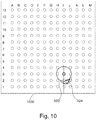
- Fig. 10 shows an alternative means of visualization. Illustrated in Fig. 10 is a rendering of a transperineal grid template that lays a matrix of circles labeled A-M and 1-13. These represent different locations where an ablation probe may be inserted. Underneath this grid 1000 the ablation zone 600 is illustrated as well as the remaining portion 124. Superimposing 600 in 124 on the grid 1000 may help an operator visualize the proper location to insert an ablation probe.
- these 3D surface renderings may possibly be generated with the help of advanced techniques, such as glass rendering.
- the system may incorporate a navigation aid that positions the MPR viewers based on a clicked untreated area as visualized in a 3D rendering.
- the user when the untreated area is visualized, the user may be able to plan an ablation within the untreated area:
- the visualization of the untreated areas plays an important role during two decision moments in an ablation procedure that is guided aby an ATPS.
- the first moment is the review and approval of the plan that is to be implanted by the user. Before starting to do so, the user can inspect his plan to assess whether there are no remaining uncovered areas in the target lesion.
- the second moment is after placement of the applicators, where small deviations from the plan are inevitable. Such deviations may introduce small untreated areas in between the applicators, which can now easily be visualized. If there are gaps, the user can decide to plan further ablations, to place an applicator in the untreated area, or to accept the gap as is. Examples may possibly provide for medical instruments with one or more of the following features:
- a computer program may be stored/distributed on a suitable medium, such as an optical storage medium or a solid-state medium supplied together with or as part of other hardware, but may also be distributed in other forms, such as via the Internet or other wired or wireless telecommunication systems. Any reference signs in the claims should not be construed as limiting the scope.
Landscapes
- Health & Medical Sciences (AREA)
- Surgery (AREA)
- Engineering & Computer Science (AREA)
- Life Sciences & Earth Sciences (AREA)
- Animal Behavior & Ethology (AREA)
- General Health & Medical Sciences (AREA)
- Biomedical Technology (AREA)
- Heart & Thoracic Surgery (AREA)
- Medical Informatics (AREA)
- Molecular Biology (AREA)
- Nuclear Medicine, Radiotherapy & Molecular Imaging (AREA)
- Veterinary Medicine (AREA)
- Public Health (AREA)
- Robotics (AREA)
- Physics & Mathematics (AREA)
- Plasma & Fusion (AREA)
- Otolaryngology (AREA)
- Magnetic Resonance Imaging Apparatus (AREA)
- Ultra Sonic Daignosis Equipment (AREA)
- Apparatus For Radiation Diagnosis (AREA)
Priority Applications (6)
| Application Number | Priority Date | Filing Date | Title |
|---|---|---|---|
| EP20169279.5A EP3895645A1 (en) | 2020-04-14 | 2020-04-14 | Ablation planning system |
| PCT/EP2021/059520 WO2021209431A1 (en) | 2020-04-14 | 2021-04-13 | Ablation planning system |
| CN202180042340.9A CN115734764A (zh) | 2020-04-14 | 2021-04-13 | 消融规划系统 |
| EP21716790.7A EP4135613B1 (en) | 2020-04-14 | 2021-04-13 | Ablation planning system |
| JP2022562340A JP7715162B2 (ja) | 2020-04-14 | 2021-04-13 | アブレーション処置システム |
| US17/918,413 US20230148138A1 (en) | 2020-04-14 | 2021-04-13 | Ablation planning system |
Applications Claiming Priority (1)
| Application Number | Priority Date | Filing Date | Title |
|---|---|---|---|
| EP20169279.5A EP3895645A1 (en) | 2020-04-14 | 2020-04-14 | Ablation planning system |
Publications (1)
| Publication Number | Publication Date |
|---|---|
| EP3895645A1 true EP3895645A1 (en) | 2021-10-20 |
Family
ID=70289312
Family Applications (2)
| Application Number | Title | Priority Date | Filing Date |
|---|---|---|---|
| EP20169279.5A Withdrawn EP3895645A1 (en) | 2020-04-14 | 2020-04-14 | Ablation planning system |
| EP21716790.7A Active EP4135613B1 (en) | 2020-04-14 | 2021-04-13 | Ablation planning system |
Family Applications After (1)
| Application Number | Title | Priority Date | Filing Date |
|---|---|---|---|
| EP21716790.7A Active EP4135613B1 (en) | 2020-04-14 | 2021-04-13 | Ablation planning system |
Country Status (5)
| Country | Link |
|---|---|
| US (1) | US20230148138A1 (https=) |
| EP (2) | EP3895645A1 (https=) |
| JP (1) | JP7715162B2 (https=) |
| CN (1) | CN115734764A (https=) |
| WO (1) | WO2021209431A1 (https=) |
Cited By (1)
| Publication number | Priority date | Publication date | Assignee | Title |
|---|---|---|---|---|
| WO2024079639A1 (en) * | 2022-10-14 | 2024-04-18 | Covidien Lp | Systems and methods for confirming position or orientation of medical device relative to target |
Families Citing this family (4)
| Publication number | Priority date | Publication date | Assignee | Title |
|---|---|---|---|---|
| CN115666431A (zh) * | 2020-05-26 | 2023-01-31 | 波士顿科学医学有限公司 | 用于不可逆电穿孔消融的用户界面上动态空间数据的叠加 |
| CN113693725B (zh) * | 2021-10-22 | 2022-02-22 | 杭州维纳安可医疗科技有限责任公司 | 进针路径规划方法、装置、设备及存储介质 |
| WO2025254964A1 (en) * | 2024-06-04 | 2025-12-11 | Medtronic Xomed Llc | Systems and methods for thyroid nodule ablation planning and tracking |
| CN119139019B (zh) * | 2024-11-19 | 2025-02-25 | 卡本(深圳)医疗器械有限公司 | 引导穿刺的计算机设备 |
Citations (2)
| Publication number | Priority date | Publication date | Assignee | Title |
|---|---|---|---|---|
| EP2666431A1 (en) * | 2012-05-22 | 2013-11-27 | Covidien LP | Surgical planning system and navigation system |
| US20150320509A1 (en) | 2014-05-09 | 2015-11-12 | Edda Technology, Inc. | System and Methods for Percutaneous Treatment Planning and Treatment Monitoring |
Family Cites Families (14)
| Publication number | Priority date | Publication date | Assignee | Title |
|---|---|---|---|---|
| US7452357B2 (en) | 2004-10-22 | 2008-11-18 | Ethicon Endo-Surgery, Inc. | System and method for planning treatment of tissue |
| US20070238981A1 (en) | 2006-03-13 | 2007-10-11 | Bracco Imaging Spa | Methods and apparatuses for recording and reviewing surgical navigation processes |
| US7693349B2 (en) | 2006-08-15 | 2010-04-06 | General Electric Company | Systems and methods for interactive image registration |
| WO2010052596A1 (en) * | 2008-11-04 | 2010-05-14 | Koninklijke Philips Electronics, N.V. | Method and system for ultrasound therapy |
| JP5731267B2 (ja) | 2011-04-25 | 2015-06-10 | 株式会社日立メディコ | 治療支援システム及び医用画像処理装置 |
| US10729499B2 (en) * | 2011-07-28 | 2020-08-04 | Koninklijke Philips N.V. | Ablation planning system |
| US9439627B2 (en) * | 2012-05-22 | 2016-09-13 | Covidien Lp | Planning system and navigation system for an ablation procedure |
| US20130316318A1 (en) * | 2012-05-22 | 2013-11-28 | Vivant Medical, Inc. | Treatment Planning System |
| US20160317224A1 (en) * | 2015-04-30 | 2016-11-03 | Covidien Lp | Microwave ablation planning and procedure systems |
| JP6078134B1 (ja) | 2015-10-15 | 2017-02-08 | 株式会社日立製作所 | 医療システム |
| US12064183B2 (en) * | 2017-03-21 | 2024-08-20 | Canon U.S.A., Inc. | Methods, apparatuses and storage mediums for ablation planning and performance |
| WO2018195221A1 (en) * | 2017-04-18 | 2018-10-25 | Intuitive Surgical Operations, Inc. | Graphical user interface for planning a procedure |
| US20190247120A1 (en) * | 2018-02-12 | 2019-08-15 | Desert Medical Imaging, LLC | Systems and methods for mri-guided interstitial thermal therapy |
| EP3574861A1 (en) * | 2018-05-28 | 2019-12-04 | Koninklijke Philips N.V. | System and method for assisting in positioning a thermal ablation device |
-
2020
- 2020-04-14 EP EP20169279.5A patent/EP3895645A1/en not_active Withdrawn
-
2021
- 2021-04-13 EP EP21716790.7A patent/EP4135613B1/en active Active
- 2021-04-13 CN CN202180042340.9A patent/CN115734764A/zh active Pending
- 2021-04-13 JP JP2022562340A patent/JP7715162B2/ja active Active
- 2021-04-13 US US17/918,413 patent/US20230148138A1/en active Pending
- 2021-04-13 WO PCT/EP2021/059520 patent/WO2021209431A1/en not_active Ceased
Patent Citations (2)
| Publication number | Priority date | Publication date | Assignee | Title |
|---|---|---|---|---|
| EP2666431A1 (en) * | 2012-05-22 | 2013-11-27 | Covidien LP | Surgical planning system and navigation system |
| US20150320509A1 (en) | 2014-05-09 | 2015-11-12 | Edda Technology, Inc. | System and Methods for Percutaneous Treatment Planning and Treatment Monitoring |
Cited By (1)
| Publication number | Priority date | Publication date | Assignee | Title |
|---|---|---|---|---|
| WO2024079639A1 (en) * | 2022-10-14 | 2024-04-18 | Covidien Lp | Systems and methods for confirming position or orientation of medical device relative to target |
Also Published As
| Publication number | Publication date |
|---|---|
| CN115734764A (zh) | 2023-03-03 |
| EP4135613B1 (en) | 2025-06-18 |
| US20230148138A1 (en) | 2023-05-11 |
| JP7715162B2 (ja) | 2025-07-30 |
| EP4135613A1 (en) | 2023-02-22 |
| WO2021209431A1 (en) | 2021-10-21 |
| JP2023521839A (ja) | 2023-05-25 |
Similar Documents
| Publication | Publication Date | Title |
|---|---|---|
| EP4135613B1 (en) | Ablation planning system | |
| US12329460B2 (en) | Determining ablation probe configuration | |
| JP6487929B2 (ja) | 外部ビーム放射線治療と小線源治療用医療用機器 | |
| CN116420107A (zh) | 使用增强现实的深脑部路径规划 | |
| CN104487859A (zh) | 用于医学仪器的图形用户界面 | |
| WO2013057609A1 (en) | Medical apparatus for displaying the catheter placement position | |
| EP3861531B1 (en) | Generation of pseudo radiographic images from optical images | |
| US11432735B2 (en) | Radiotherapy system for accurate locating of 3D objects from magnetic resonance images | |
| US9192788B2 (en) | Therapeutic apparatus, computer program product, and method for determining an achievable target region for high intensity focused ultrasound | |
| US20150273245A1 (en) | Medical apparatus for determining a maximum energy map | |
| US10272270B2 (en) | Coordinate transformation of graphical objects registered to a magnetic resonance image | |
| EP4107704A1 (en) | Image segmentation system |
Legal Events
| Date | Code | Title | Description |
|---|---|---|---|
| PUAI | Public reference made under article 153(3) epc to a published international application that has entered the european phase |
Free format text: ORIGINAL CODE: 0009012 |
|
| STAA | Information on the status of an ep patent application or granted ep patent |
Free format text: STATUS: THE APPLICATION HAS BEEN PUBLISHED |
|
| AK | Designated contracting states |
Kind code of ref document: A1 Designated state(s): AL AT BE BG CH CY CZ DE DK EE ES FI FR GB GR HR HU IE IS IT LI LT LU LV MC MK MT NL NO PL PT RO RS SE SI SK SM TR |
|
| B565 | Issuance of search results under rule 164(2) epc |
Effective date: 20201030 |
|
| STAA | Information on the status of an ep patent application or granted ep patent |
Free format text: STATUS: THE APPLICATION IS DEEMED TO BE WITHDRAWN |
|
| 18D | Application deemed to be withdrawn |
Effective date: 20220421 |