EP3894821B1 - Test d'étanchéité d'un spécimen d'essai rempli de liquide - Google Patents
Test d'étanchéité d'un spécimen d'essai rempli de liquide Download PDFInfo
- Publication number
- EP3894821B1 EP3894821B1 EP20745164.2A EP20745164A EP3894821B1 EP 3894821 B1 EP3894821 B1 EP 3894821B1 EP 20745164 A EP20745164 A EP 20745164A EP 3894821 B1 EP3894821 B1 EP 3894821B1
- Authority
- EP
- European Patent Office
- Prior art keywords
- test
- liquid
- detector
- test chamber
- gas
- Prior art date
- Legal status (The legal status is an assumption and is not a legal conclusion. Google has not performed a legal analysis and makes no representation as to the accuracy of the status listed.)
- Active
Links
- 238000012360 testing method Methods 0.000 title claims description 214
- 239000007788 liquid Substances 0.000 title claims description 88
- 239000007789 gas Substances 0.000 claims description 84
- 238000000034 method Methods 0.000 claims description 31
- 238000001514 detection method Methods 0.000 claims description 20
- 239000012159 carrier gas Substances 0.000 claims description 17
- 239000002245 particle Substances 0.000 claims description 9
- 239000003792 electrolyte Substances 0.000 claims description 7
- 238000011010 flushing procedure Methods 0.000 claims description 3
- 238000010521 absorption reaction Methods 0.000 claims description 2
- 239000004065 semiconductor Substances 0.000 claims description 2
- 239000000126 substance Substances 0.000 claims description 2
- 238000003780 insertion Methods 0.000 claims 1
- 230000037431 insertion Effects 0.000 claims 1
- 238000009825 accumulation Methods 0.000 description 6
- 239000000523 sample Substances 0.000 description 6
- 239000003570 air Substances 0.000 description 5
- 238000009792 diffusion process Methods 0.000 description 5
- 238000005259 measurement Methods 0.000 description 5
- 239000000700 radioactive tracer Substances 0.000 description 5
- HBBGRARXTFLTSG-UHFFFAOYSA-N Lithium ion Chemical compound [Li+] HBBGRARXTFLTSG-UHFFFAOYSA-N 0.000 description 4
- 239000007792 gaseous phase Substances 0.000 description 4
- 229910001416 lithium ion Inorganic materials 0.000 description 4
- 239000012071 phase Substances 0.000 description 4
- 239000003507 refrigerant Substances 0.000 description 4
- IEJIGPNLZYLLBP-UHFFFAOYSA-N dimethyl carbonate Chemical compound COC(=O)OC IEJIGPNLZYLLBP-UHFFFAOYSA-N 0.000 description 3
- 239000011244 liquid electrolyte Substances 0.000 description 3
- 239000012528 membrane Substances 0.000 description 3
- 239000000203 mixture Substances 0.000 description 3
- IJGRMHOSHXDMSA-UHFFFAOYSA-N Atomic nitrogen Chemical compound N#N IJGRMHOSHXDMSA-UHFFFAOYSA-N 0.000 description 2
- CURLTUGMZLYLDI-UHFFFAOYSA-N Carbon dioxide Chemical compound O=C=O CURLTUGMZLYLDI-UHFFFAOYSA-N 0.000 description 2
- 239000012050 conventional carrier Substances 0.000 description 2
- 238000010586 diagram Methods 0.000 description 2
- 239000007791 liquid phase Substances 0.000 description 2
- 239000000443 aerosol Substances 0.000 description 1
- 238000004378 air conditioning Methods 0.000 description 1
- 239000012080 ambient air Substances 0.000 description 1
- QVGXLLKOCUKJST-UHFFFAOYSA-N atomic oxygen Chemical compound [O] QVGXLLKOCUKJST-UHFFFAOYSA-N 0.000 description 1
- 239000001569 carbon dioxide Substances 0.000 description 1
- 229910002092 carbon dioxide Inorganic materials 0.000 description 1
- 230000008020 evaporation Effects 0.000 description 1
- 238000001704 evaporation Methods 0.000 description 1
- 235000013305 food Nutrition 0.000 description 1
- 239000001307 helium Substances 0.000 description 1
- 229910052734 helium Inorganic materials 0.000 description 1
- SWQJXJOGLNCZEY-UHFFFAOYSA-N helium atom Chemical compound [He] SWQJXJOGLNCZEY-UHFFFAOYSA-N 0.000 description 1
- 230000001771 impaired effect Effects 0.000 description 1
- 239000003595 mist Substances 0.000 description 1
- 229910052757 nitrogen Inorganic materials 0.000 description 1
- 239000001301 oxygen Substances 0.000 description 1
- 229910052760 oxygen Inorganic materials 0.000 description 1
- 238000004806 packaging method and process Methods 0.000 description 1
- 230000005855 radiation Effects 0.000 description 1
- 238000005057 refrigeration Methods 0.000 description 1
Images

Classifications
-
- G—PHYSICS
- G01—MEASURING; TESTING
- G01M—TESTING STATIC OR DYNAMIC BALANCE OF MACHINES OR STRUCTURES; TESTING OF STRUCTURES OR APPARATUS, NOT OTHERWISE PROVIDED FOR
- G01M3/00—Investigating fluid-tightness of structures
- G01M3/02—Investigating fluid-tightness of structures by using fluid or vacuum
- G01M3/26—Investigating fluid-tightness of structures by using fluid or vacuum by measuring rate of loss or gain of fluid, e.g. by pressure-responsive devices, by flow detectors
-
- G—PHYSICS
- G01—MEASURING; TESTING
- G01M—TESTING STATIC OR DYNAMIC BALANCE OF MACHINES OR STRUCTURES; TESTING OF STRUCTURES OR APPARATUS, NOT OTHERWISE PROVIDED FOR
- G01M3/00—Investigating fluid-tightness of structures
- G01M3/02—Investigating fluid-tightness of structures by using fluid or vacuum
- G01M3/04—Investigating fluid-tightness of structures by using fluid or vacuum by detecting the presence of fluid at the leakage point
- G01M3/20—Investigating fluid-tightness of structures by using fluid or vacuum by detecting the presence of fluid at the leakage point using special tracer materials, e.g. dye, fluorescent material, radioactive material
- G01M3/22—Investigating fluid-tightness of structures by using fluid or vacuum by detecting the presence of fluid at the leakage point using special tracer materials, e.g. dye, fluorescent material, radioactive material for pipes, cables or tubes; for pipe joints or seals; for valves; for welds; for containers, e.g. radiators
- G01M3/226—Investigating fluid-tightness of structures by using fluid or vacuum by detecting the presence of fluid at the leakage point using special tracer materials, e.g. dye, fluorescent material, radioactive material for pipes, cables or tubes; for pipe joints or seals; for valves; for welds; for containers, e.g. radiators for containers, e.g. radiators
- G01M3/229—Investigating fluid-tightness of structures by using fluid or vacuum by detecting the presence of fluid at the leakage point using special tracer materials, e.g. dye, fluorescent material, radioactive material for pipes, cables or tubes; for pipe joints or seals; for valves; for welds; for containers, e.g. radiators for containers, e.g. radiators removably mounted in a test cell
-
- G—PHYSICS
- G01—MEASURING; TESTING
- G01M—TESTING STATIC OR DYNAMIC BALANCE OF MACHINES OR STRUCTURES; TESTING OF STRUCTURES OR APPARATUS, NOT OTHERWISE PROVIDED FOR
- G01M3/00—Investigating fluid-tightness of structures
- G01M3/02—Investigating fluid-tightness of structures by using fluid or vacuum
- G01M3/04—Investigating fluid-tightness of structures by using fluid or vacuum by detecting the presence of fluid at the leakage point
- G01M3/20—Investigating fluid-tightness of structures by using fluid or vacuum by detecting the presence of fluid at the leakage point using special tracer materials, e.g. dye, fluorescent material, radioactive material
- G01M3/202—Investigating fluid-tightness of structures by using fluid or vacuum by detecting the presence of fluid at the leakage point using special tracer materials, e.g. dye, fluorescent material, radioactive material using mass spectrometer detection systems
- G01M3/205—Accessories or associated equipment; Pump constructions
-
- G—PHYSICS
- G01—MEASURING; TESTING
- G01M—TESTING STATIC OR DYNAMIC BALANCE OF MACHINES OR STRUCTURES; TESTING OF STRUCTURES OR APPARATUS, NOT OTHERWISE PROVIDED FOR
- G01M3/00—Investigating fluid-tightness of structures
- G01M3/02—Investigating fluid-tightness of structures by using fluid or vacuum
- G01M3/04—Investigating fluid-tightness of structures by using fluid or vacuum by detecting the presence of fluid at the leakage point
- G01M3/20—Investigating fluid-tightness of structures by using fluid or vacuum by detecting the presence of fluid at the leakage point using special tracer materials, e.g. dye, fluorescent material, radioactive material
- G01M3/202—Investigating fluid-tightness of structures by using fluid or vacuum by detecting the presence of fluid at the leakage point using special tracer materials, e.g. dye, fluorescent material, radioactive material using mass spectrometer detection systems
-
- H—ELECTRICITY
- H01—ELECTRIC ELEMENTS
- H01M—PROCESSES OR MEANS, e.g. BATTERIES, FOR THE DIRECT CONVERSION OF CHEMICAL ENERGY INTO ELECTRICAL ENERGY
- H01M10/00—Secondary cells; Manufacture thereof
- H01M10/05—Accumulators with non-aqueous electrolyte
- H01M10/052—Li-accumulators
-
- H—ELECTRICITY
- H01—ELECTRIC ELEMENTS
- H01M—PROCESSES OR MEANS, e.g. BATTERIES, FOR THE DIRECT CONVERSION OF CHEMICAL ENERGY INTO ELECTRICAL ENERGY
- H01M10/00—Secondary cells; Manufacture thereof
- H01M10/05—Accumulators with non-aqueous electrolyte
- H01M10/052—Li-accumulators
- H01M10/0525—Rocking-chair batteries, i.e. batteries with lithium insertion or intercalation in both electrodes; Lithium-ion batteries
-
- H—ELECTRICITY
- H01—ELECTRIC ELEMENTS
- H01M—PROCESSES OR MEANS, e.g. BATTERIES, FOR THE DIRECT CONVERSION OF CHEMICAL ENERGY INTO ELECTRICAL ENERGY
- H01M10/00—Secondary cells; Manufacture thereof
- H01M10/42—Methods or arrangements for servicing or maintenance of secondary cells or secondary half-cells
- H01M10/4228—Leak testing of cells or batteries
-
- H—ELECTRICITY
- H01—ELECTRIC ELEMENTS
- H01M—PROCESSES OR MEANS, e.g. BATTERIES, FOR THE DIRECT CONVERSION OF CHEMICAL ENERGY INTO ELECTRICAL ENERGY
- H01M2300/00—Electrolytes
- H01M2300/0017—Non-aqueous electrolytes
-
- H—ELECTRICITY
- H01—ELECTRIC ELEMENTS
- H01M—PROCESSES OR MEANS, e.g. BATTERIES, FOR THE DIRECT CONVERSION OF CHEMICAL ENERGY INTO ELECTRICAL ENERGY
- H01M2300/00—Electrolytes
- H01M2300/0017—Non-aqueous electrolytes
- H01M2300/0025—Organic electrolyte
-
- Y—GENERAL TAGGING OF NEW TECHNOLOGICAL DEVELOPMENTS; GENERAL TAGGING OF CROSS-SECTIONAL TECHNOLOGIES SPANNING OVER SEVERAL SECTIONS OF THE IPC; TECHNICAL SUBJECTS COVERED BY FORMER USPC CROSS-REFERENCE ART COLLECTIONS [XRACs] AND DIGESTS
- Y02—TECHNOLOGIES OR APPLICATIONS FOR MITIGATION OR ADAPTATION AGAINST CLIMATE CHANGE
- Y02E—REDUCTION OF GREENHOUSE GAS [GHG] EMISSIONS, RELATED TO ENERGY GENERATION, TRANSMISSION OR DISTRIBUTION
- Y02E60/00—Enabling technologies; Technologies with a potential or indirect contribution to GHG emissions mitigation
- Y02E60/10—Energy storage using batteries
Definitions
- the invention relates to a method for leak detection on a liquid-filled test specimen.
- test piece filled with test gas is exposed to a negative pressure in a test chamber by the test chamber being evacuated. Due to the resulting pressure difference, tracer gas enters the test chamber through a possible leak in the test object, from where it is fed to a sensor for detecting the tracer gas.
- a test gas such as helium
- methods are known in which gases are used as the test gas in the test object are already included when the test specimen is brought into the test chamber. It is then not necessary to actively fill the test object with test gas.
- the gas already contained in the test specimen when it is introduced into the film chamber can be components of air, such as nitrogen, oxygen or carbon dioxide. Gases can also be used as a test gas which contain or consist of flavorings of a product contained in the test piece, such as coffee flavorings in the case of coffee. A further possibility is to use gases as test gas, which are generated by a product contained in the test piece, such as a foodstuff. In the case of coffee, this can be CO 2 , which forms within a coffee package after a few hours. Further state of the art is out U.S. 2001/016278 A1 , EP 1 522 838 B1 , U.S. 5,131,263 A , U.S. 2017/108401 A1 and US 2013/199274 A1 known.
- the invention deals with leak detection on a test specimen that is filled with a liquid and in which no gas present in the test specimen is available as a test gas and which should not or cannot be actively filled with a separate test gas.
- batteries filled with electrolyte liquids such as a lithium-ion battery filled with dimethyl carbonate as the electrolyte.
- the leaked gas is often detected with the aid of a gas detector.
- the test item is tested for leaks using the vacuum method.
- the test item is placed in a vacuum chamber. Gas that escapes into the vacuum chamber through a leak in the test object is continuously conveyed out of the vacuum chamber by the vacuum system.
- the leakage gas in the vacuum system is selectively detected with a suitable sensor. If the pressure is low enough, it will move Leakage gas sufficiently quickly by diffusion or molecular free towards the sensor.
- a carrier gas method is used in particular when the working pressure in the vacuum chamber is much greater than 1 mbar. In such cases, the diffusion rate of the leak gas to be detected in the vacuum chamber is too slow.
- a carrier gas method is, for example, in WO 2005/054806 A1 described by passing a flow of carrier gas through a test chamber containing a test specimen. The test chamber is flushed with the carrier gas. Test gas escaping through the test object is transported out of the test chamber with the carrier gas flow and fed to a test gas sensor.
- test test objects filled with a liquid refrigerant e.g. heat exchangers - for leaks.
- a special feature of these test specimens is that the liquid refrigerant is contained in the test specimen under overpressure in order to maintain the liquid phase of the refrigerant.
- a sniffer probe is guided along the areas of the test specimen to be tested for leaks. The sniffer probe sucks in air from the environment of the test object and picks up escaping leak gas, which is selectively determined with a corresponding sensor and thereby differentiated from the air components sucked in.
- the sniffer leak detection method cannot be used because in the event of a leak, no leakage gas escapes to the outside.
- the sniffer leak detection method cannot be used because in the event of a leak, no leakage gas escapes to the outside.
- batteries that are filled with a liquid electrolyte with low vapor pressure and in which there is a negative pressure air from the external test specimen environment penetrates into the interior of the test specimen in the event of a leak. The leak cannot be detected using a sniffer probe.
- the leak detection methods described above using a tracer gas contained in the test specimen are also not applicable or at least inaccurate, because the liquid in the test specimen when evacuating the external environment of the test specimen gets into the opening or channel of the leak and prevents or at least significantly the outflow of a tracer gas impaired. A quantity of tracer gas detected outside of the test object is then no longer representative of the presence or size of a leak in the test object.
- EP 1 522 838 B1 describes a method in which a test specimen filled with an electrolyte is contained in a test chamber whose internal pressure is lower than the pressure inside the test specimen. Cleaned air or ambient air is supplied to the test chamber as a carrier gas in order to supply liquid components escaping from the test object to a detector according to the carrier gas method.
- the object of the invention is to provide a leak detection method for a liquid-filled test specimen whose internal pressure is less than or equal to atmospheric pressure.
- test specimen filled with a liquid is placed in a test chamber.
- the liquid is contained inside the specimen.
- Internal pressure inside the specimen is lower than atmospheric pressure.
- the test chamber After placing the specimen in the test chamber, the test chamber is evacuated to a pressure below the internal pressure in the specimen and below atmospheric pressure. Residual gas components contained in the test chamber are sucked off together with gas components desorbing from at least one test chamber wall and possible parts of the liquid that enter the test chamber through a leak from the test specimen and fed to a detector without a carrier gas being fed to the test chamber becomes. Parts or particles of the liquid escaping from the test object are selectively detected with a detector.
- no carrier gas is supplied to the test chamber from the outside, which originates, for example, from a carrier gas source connected to the test chamber or is taken from the environment of the test chamber.
- a carrier gas source connected to the test chamber or is taken from the environment of the test chamber.
- a carrier gas is not required.
- the parts of the liquid that escaped from the leak can be molecular particles in vaporized form. Evaporation can occur when escaping from the test object. Typically, the liquid evaporates at the exit of the leak channel, which runs through the leaking wall of the test object.
- the liquid can have a vapor pressure that is less than 500 mbar at room temperature (approx. 15 °C to 25 °C).
- the device under test can be a battery, such as a lithium-ion battery, and the liquid can be an electrolyte, such as dimethyl carbonate.
- the test chamber can be designed as a rigid test chamber with rigid walls.
- the test chamber can also be designed as a film chamber, which is characterized in that it has at least one flexible wall area that is sucked onto the test specimen during evacuation and reduces the volume of the film chamber.
- film chambers in particular with walls consisting entirely of a flexible film, offer the advantage that the walls sucked onto the test specimen support the test specimen, which is particularly advantageous in the case of a flexible test specimen.
- the detector has a sensor that selectively detects the parts or particles of the liquid to be detected and can thereby distinguish them from other parts or gases.
- the portions of the leaked liquid can be in liquid form and fed to the detector.
- the detector must be able to analyze liquids and to selectively detect the liquid contained in the test object.
- the leaked liquid can be fed to the detector in the form of a mist or aerosol, for example.
- the liquid evaporates when escaping from a leak in the test specimen and the parts of the liquid that have escaped are fed to the detector in vaporized form, ie in the gaseous phase.
- the detector must then be designed as a gas detector and be able to analyze gases and to selectively distinguish the liquid in the sample in its gaseous phase from other gases.
- the decisive factor here is that the liquid contained in the test object only changes from the liquid phase to its gaseous phase when it leaves the test object, i.e. outside the test object or in the opening or channel of the leak. Thus, no gas present in the test piece is used as the test gas because the liquid inside the test piece is in liquid form, even if the liquid escapes through a leak and vaporizes in the process.
- the detector for the parts of the liquid to be detected can be a gas detector such as a mass spectrometer, a gas chromatograph, an infrared radiation absorption detector or a detector with chemical sensors or semiconductor sensors.
- a gas detector such as a mass spectrometer, a gas chromatograph, an infrared radiation absorption detector or a detector with chemical sensors or semiconductor sensors.
- the test chamber is not supplied with a constant stream of carrier gas, as is the case with conventional carrier gas methods for gas leak detection. Rather, the residual gas components within the test chamber and the gas components desorbing from the test chamber walls are used to transport parts or particles of the liquid that have leaked into the test specimen into the test chamber to the detector. A mixture of gas components from inside the test chamber or from the test chamber walls and from parts or particles of the liquid contained in the test specimen is fed to the detector and analyzed with the aid of the detector in order to detect the parts of the liquid transported with the gas.
- the gas flow transporting the parts of the liquid is preferably only fed to the detector when a pressure limit value has been reached in the test chamber or in the connecting line between the test chamber and the vacuum pump sucking off the test chamber.
- This pressure limit can be between about 2 mbar and 50 mbar and is preferably less than 20 mbar.
- the vacuum pump which is preferably a diaphragm pump, can be connected to the test chamber and/or to the gas line connecting the vacuum pump and the test chamber via a valve. At the beginning of the evacuation of the test chamber, the valve is closed. When the pressure limit is reached, the valve is opened and a partial flow reaches the detector, while the remaining main gas flow continues to be sucked off with the diaphragm pump.
- test specimen in the test chamber is flushed with a flushing gas in order to remove parts of the liquid adhering to the test specimen.
- the test specimen is preferably flushed with flushing gas before the actual leak detection takes place, e.g. before the test chamber is evacuated.
- a calibration can be carried out using a test leak that is filled with a test liquid.
- the test leak can be in the form of a capillary leak in which the test liquid exits through a capillary of known dimensions formed in the wall of the test leak.
- the test leak can be a permeation liquid leak, in which an area of the wall of the test leak is designed as a membrane with known permeation properties for the test liquid.
- a test specimen 14 filled with a liquid 12 is contained in a test chamber 16 .
- the test object 14 is a battery that is filled with a liquid electrolyte.
- the test chamber 16 is a conventional rigid test chamber.
- the test chamber 16 is provided with a vacuum connection 22 to which a vacuum pump 24 is connected, with which the test chamber 16 can be evacuated.
- the vacuum pump 24 has at least one vacuum pump in the form of a diaphragm pump.
- the test chamber 16 and the vacuum pump 24 are connected to one another in a gas-conducting manner by a connecting line 26 , so that the vacuum pump 24 can suck gas out of the test chamber 16 via the connecting line 26 .
- a detector 28 for analyzing and detecting parts of the liquid 12 is connected to the connecting line 26 connecting the vacuum pump 24 to the test chamber 16 .
- the detector 28 is a selective gas detector, for example in the form of a mass spectrometer, whose sensor can selectively detect molecular particles in the liquid 12 and distinguish them from other gases.
- the detector 28 is part of a mass spectrometric vacuum system 20 which has a fore-vacuum pump 19 and a high-vacuum pump 18 for evacuating the mass spectrometer 28 .
- the detector 28 is connected in a gas-conducting manner to the connecting line 26 via a gas-conducting detection line 21 .
- the detection line 21 is provided with a throttle 38 for throttling the gas flow branched off from the connection line 26 and with a valve V2 for selectively closing the detection line 21 .
- a pressure sensor 17 In order to measure the pressure within the connecting line 26, it is connected to a pressure sensor 17 in a gas-conducting manner.
- Parts of the liquid 12 escape from a leak in the test object 14 and get into the test chamber 16.
- the liquid 12 escapes from the test object 14, it can evaporate, so that the parts of the liquid 12 that have escaped can be present in gaseous form.
- the detector 28 is operated as a mass spectrometer in the vacuum system 20 with a pressure that is lower than the pressure inside the test chamber 16 and lower than the pressure at the connection point 40 between the connection line 26 and the detection line 21 .
- the membrane pump 24 In the case of the diaphragm pump 24 used according to the invention for sucking off the test chamber 16, however, no high vacuum is generated within the test chamber 16. Rather, the membrane pump 24 generates a pressure in the range of a few millibars. The membrane pump 24 sucks from the test chamber 16 remaining residual gas components.
- These gas components i.e. residual gas components from the test chamber 16 and gas components desorbing from its walls, absorb parts of the liquid 12 which enter the test chamber 16 from the test object 14 through a leak. These parts of the liquid 12 are fed to the detector 28 .
- the vacuum pressure inside the test chamber 16 is a few millibars.
- the diffusion of the parts of the liquid 12 that have escaped and evaporated from the test object 14 is still sluggish at this pressure.
- Of the Transport of the leaked parts of the liquid 12 to the detector 28 is accelerated with the gas components without using a carrier gas and supplying it to the test chamber 16 from the outside.
- valve V2 can be opened for detection. During the accumulation phase, valve V2 can be closed or open.
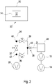
- This in 2 illustrated second embodiment differs from the first embodiment according to 1 in that the section 30 of the detection line 21 having the valve V2 is bridged by a section 36 having a further valve V3, so that the valves V2, V3 are connected in parallel.
- a valve V1 is provided in the section 32 of the connecting line 26 between the connection point 40 of the connecting line 26 with the section 30 and the connection point 42 between the connecting line 26 and the section 36 .
- the valve V1 is open.
- the valve V2 is then closed.
- the detector 28 of the second exemplary embodiment is also a mass spectrometer with an independent vacuum system.
- the inlet area to the mass spectrometer is also controlled by the vacuum pump 24 evacuated.
- valve V2 remains closed while valve V1 is closed and valve V3 is opened to evacuate the inlet area to the mass spectrometer to the required vacuum pressure.
- the valve V1 is closed for the measurement operation and the valves V2 and V3 are opened, so that the measurement medium from the test chamber 16 is transported past the detector 28 via the vacuum pump 24 .
- the liquid can be dimethyl carbonate, which is used as an electrolyte in a lithium-ion battery.
- a vacuum pressure prevails in the lithium-ion battery, which is greater than the pressure inside the test chamber 16 in the area outside the test specimen 14 after the test chamber 16 was evacuated.
- the liquid electrolyte evaporates when escaping from the specimen 14 through a leak, so that the parts of the liquid 12 to be detected can be present in the form of molecular particles of a gaseous phase.
- the parts of the liquid 12 are transported through the test chamber 16 and via the lines 26 , 30 , 21 into the detector 28 and further to the pump 24 via the line 36 .
- a mixture of gas components is formed, which originate from the interior of the test chamber 16 and from the walls of the test chamber 16, and transported parts of the liquid 12.
- the selective sensor of the mass spectrometric detector 28 detects the parts of the liquid 12 and is able to distinguish them from the gas components of the test chamber 16. Detecting the portions of the liquid 12 that has escaped from the leak in the test specimen 14 serves as an indication of the presence of a leak in the test specimen. The size of a leak can be deduced from the amount of detected parts of the liquid 12 .
- valves V1, V3 are closed during the accumulation phase.
- valve V2 can also be closed. After a predetermined time has elapsed, the valve V2 is opened so that the accumulated portions of the liquid 12 are supplied to the detector 28.
- the accumulated gas can also be transported through the gas components from the test chamber 16 to the detector 28 after the accumulation phase.
- no carrier gas is fed to the evacuated test chamber 16 from the outside.
- the detector 28 is brought to a lower pressure than the pressure prevailing in the test chamber 16 with the aid of the vacuum pumps 18 , 19 .
- the valve V2 is opened, the accumulated parts of the liquid 12 are transported to the detector 18 and detected there.
- the conductance of the throttle 38 and the threshold value of the pressure before (on the left in the figures) the throttle 38 at which the valve V2 is opened are selected in such a way that the gas inlet via the throttle 38 into the chamber volume of the mass spectrometer 28 does not cause a pressure increase of causes more than 10 -4 mbar.
- the pressure threshold under laboratory conditions is preferably approximately 5 mbar.
- a signal is generated on a characteristic measurement mass for a characteristic component of the liquid 12 (electrolyte component).
- the measurement signal is compared with a threshold value, with a leak in the test object 14 being considered to be present if the threshold value is exceeded.
- the valve V2 is closed, the test chamber is vented and, if necessary, the test piece 14 is removed from the test chamber 16 .
- the method according to the invention does not require a high-quality vacuum pump for evacuating the test chamber 16, such as a high-vacuum pump, but only a simple vacuum pump, such as a diaphragm pump, which can achieve a final pressure of less than 10 mbar.
- An essential difference between the two exemplary embodiments is that in the exemplary embodiment in 2 after closing the valve V1 and opening the valves V2, V3 after falling below the specified pressure threshold value, a shorter distance has to be covered from the throttle 38 to the mass spectrometer 28 than in the exemplary embodiment in FIG 1 .
- the pressure within the detection line 21 is low, namely less than 10 -4 mbar, so that there are molecularly free movement conditions for the gas in this area. The time it takes for the gases to propagate to the mass spectrometer 28 is therefore negligible.
- the pressure within the lines 26, 30, 32, 36 is, for example, 5 mbar.
- viscous flow conditions prevail, which means that the measuring gas has to diffuse through the residual gas along this path, which causes a time delay.
- This diffusion distance is in 1 from the connection point 40 between the connection line 26 and the vacuum line 21 to the throttle 38 is longer than the diffusion path in 2 between the connection point 44 of the lines 30, 36, 21 and the throttle 38.
Claims (14)
- Procédé de test d'étanchéité d'un sujet de test (14) rempli d'un liquide (12) présentant une pression interne inférieure à la pression atmosphérique, comprenant les étapes suivantes consistant à :introduire le sujet de test (14) dans une chambre de test (16),mettre sous vide la chambre de test (16) à une pression qui est inférieure à la pression interne à l'intérieur du sujet de test (14) ;extraire des constituants de gaz résiduel hors de la chambre de test par aspiration, conjointement avec les constituants gazeux qui se désorbent d'une paroi de la chambre de test et des parties du liquide qui sont sorties du sujet de test à travers une fuite dans ledit sujet de test, sans qu'un gaz porteur soit introduit dans la chambre de test depuis l'extérieur ; ettransporter vers un détecteur (28) les constituants de gaz résiduel extraits par aspiration conjointement avec les parties du liquide qui sont sorties du sujet de test,caractérisé par l'étape consistant àdétecter au moyen d'un détecteur (28) de parties du liquide (12) qui sont sorties à travers une fuite dans le sujet de test (14), aucun gaz présent dans le sujet de test n'étant utilisé comme gaz de test pour la détection de fuite.
- Procédé selon la revendication 1, caractérisé en ce que les parties transportées du liquide (12) sont des particules moléculaires sous forme évaporée.
- Procédé selon la revendication 1 ou 2, caractérisé en ce que le liquide (12) présente à température ambiante une pression de vapeur inférieure à 500 mbar.
- Procédé selon l'une quelconque des revendications précédentes, caractérisé en ce que le sujet de test (14) est une batterie et le liquide est un électrolyte.
- Procédé selon l'une quelconque des revendications précédentes, caractérisé en ce que la chambre de test (16) est une chambre de test rigide ou une chambre à film.
- Procédé selon l'une quelconque des revendications précédentes, caractérisé en ce que le détecteur (28) comprend un capteur sélectif pour les parties du liquide à détecter.
- Procédé selon la revendication 6, caractérisé en ce que le détecteur (28) est un détecteur de gaz tel qu'un spectromètre de masse, un chromatographe en phase gazeuse, un détecteur d'absorption infrarouge ou un détecteur à capteurs chimiques ou à semi-conducteurs.
- Procédé selon l'une quelconque des revendications précédentes, caractérisé en ce que le détecteur (28) fonctionne dans un système de vide avec une pression inférieure à la pression à l'intérieur de la chambre de test (16).
- Procédé selon l'une quelconque des revendications précédentes, caractérisé en ce que les constituants gazeux et les parties du liquide à détecter ne sont amenés au détecteur (28) que lorsqu'une valeur limite de pression prédéfinie est atteinte dans la chambre de test.
- Procédé selon la revendication 9, caractérisé en ce que la valeur limite de pression est comprise entre 2 et 100 mbar et est de préférence inférieure à 10 mbar.
- Procédé selon la revendication 9 ou 10, caractérisé en ce que le détecteur est relié à la chambre de test (16) par l'intermédiaire d'une soupape (V2) qui est fermée au début de l'évacuation de la chambre de test et qui n'est ouverte que lorsque la valeur limite de pression est atteinte.
- Procédé selon l'une quelconque des revendications précédentes, caractérisé en ce que le sujet de test (14) est rincé avec un gaz de rinçage après son introduction dans la chambre de test (16).
- Procédé selon l'une quelconque des revendications précédentes, caractérisé en ce qu'une accumulation des parties du liquide (12) sortant du sujet de test (14) a lieu dans la chambre de test (16) ou dans la conduite de raccordement pendant une période de temps avant que la détection des parties ait lieu avec le détecteur (28).
- Procédé selon l'une quelconque des revendications précédentes, caractérisé en ce qu'avant l'introduction du sujet de test (14) dans la chambre de test (16), un calibrage du détecteur est effectué avec une fuite étalon contenant un liquide de test, la fuite étalon étant introduite dans la chambre de test, la chambre de test étant évacuée et des parties du liquide sortant de la fuite étalon étant détectées avec le détecteur (28).
Applications Claiming Priority (2)
| Application Number | Priority Date | Filing Date | Title |
|---|---|---|---|
| DE102019121462.9A DE102019121462B4 (de) | 2019-08-08 | 2019-08-08 | Verfahren zur Dichtheitsprüfung eines flüssigkeitsgefüllten Prüflings |
| PCT/EP2020/070661 WO2021023513A1 (fr) | 2019-08-08 | 2020-07-22 | Test d'étanchéité d'un sujet de test rempli de liquide |
Publications (2)
| Publication Number | Publication Date |
|---|---|
| EP3894821A1 EP3894821A1 (fr) | 2021-10-20 |
| EP3894821B1 true EP3894821B1 (fr) | 2022-06-29 |
Family
ID=71784043
Family Applications (1)
| Application Number | Title | Priority Date | Filing Date |
|---|---|---|---|
| EP20745164.2A Active EP3894821B1 (fr) | 2019-08-08 | 2020-07-22 | Test d'étanchéité d'un spécimen d'essai rempli de liquide |
Country Status (8)
| Country | Link |
|---|---|
| US (1) | US20220181709A1 (fr) |
| EP (1) | EP3894821B1 (fr) |
| JP (1) | JP2022544885A (fr) |
| KR (1) | KR20220042049A (fr) |
| CN (1) | CN113853517A (fr) |
| DE (1) | DE102019121462B4 (fr) |
| TW (1) | TW202113320A (fr) |
| WO (1) | WO2021023513A1 (fr) |
Families Citing this family (2)
| Publication number | Priority date | Publication date | Assignee | Title |
|---|---|---|---|---|
| DE102021107055A1 (de) | 2021-03-22 | 2022-09-22 | Inficon Gmbh | Funktionsprüfung einer Leckdetektionsvorrichtung für die Dichtheitsprüfung eines mit einer Flüssigkeit gefüllten Prüflings |
| CN113252257B (zh) * | 2021-06-10 | 2021-09-10 | 山东奥扬新能源科技股份有限公司 | 一种电池包气密性检测设备 |
Citations (1)
| Publication number | Priority date | Publication date | Assignee | Title |
|---|---|---|---|---|
| US20130199274A1 (en) * | 2010-07-05 | 2013-08-08 | Marunaka Co., Ltd. | Leakage inspection apparatus and leakage inspection method |
Family Cites Families (17)
| Publication number | Priority date | Publication date | Assignee | Title |
|---|---|---|---|---|
| DE58906917D1 (de) * | 1989-12-15 | 1994-03-17 | Alcatel Hochvakuumtechnik Gmbh | Vorrichtung und Verfahren zur Leckprüfung. |
| EP0791814A3 (fr) * | 1997-05-26 | 1997-11-26 | Martin Lehmann | Méthode pour tester les fuites et appareil pour tester les fuites |
| JP4671462B2 (ja) * | 2000-02-22 | 2011-04-20 | パナソニック株式会社 | ニッケル水素二次電池の気密検査方法 |
| US20050079620A1 (en) * | 2003-10-10 | 2005-04-14 | Eberhard Douglas P. | Leak testing of hermetic enclosures for implantable energy storage devices |
| US7448256B2 (en) | 2003-12-05 | 2008-11-11 | Sensistor Technologies Ab | System and method for determining the leakproofness of an object |
| CN101151514A (zh) * | 2005-02-28 | 2008-03-26 | 高级技术材料公司 | 用于流体分配容器的泄漏测试和鉴定的设备及方法 |
| US7497110B2 (en) * | 2007-02-28 | 2009-03-03 | Varian, Inc. | Methods and apparatus for test gas leak detection |
| DE102007057944A1 (de) * | 2007-12-01 | 2009-06-04 | Inficon Gmbh | Verfahren und Vorrichtung zur Dichtheitsprüfung |
| EP2447694B1 (fr) * | 2010-10-28 | 2014-05-21 | Boehringer Ingelheim Pharma GmbH & Co. KG | Fuite d'essai pour le contrôle de systèmes de mesure de fuites |
| DE102011107334B4 (de) * | 2011-07-14 | 2023-03-16 | Leybold Gmbh | Lecksucheinrichtung sowie Verfahren zum Überprüfen von Gegenständen auf Dichtigkeit mittels einer Lecksucheinrichtung |
| FR2993659B1 (fr) * | 2012-07-23 | 2014-08-08 | Adixen Vacuum Products | Procede et installation de detection pour le controle d'etancheite d'emballages de produits scelles |
| DE102014205032A1 (de) * | 2014-03-18 | 2015-09-24 | Inficon Gmbh | Dichteanstiegsmessung in Folienkammer |
| DE102014219481A1 (de) * | 2014-09-25 | 2016-03-31 | Inficon Gmbh | Vorrichtung und Verfahren zum Kalibrieren einer Folienkammer zur Leckdetektion |
| DE102014224799A1 (de) | 2014-12-03 | 2016-06-09 | Inficon Gmbh | Dichtheitsprüfung mit Trägergas in Folienkammer |
| DE102015217598A1 (de) * | 2015-09-15 | 2017-03-16 | Inficon Gmbh | Leckdetektion beim Evakuieren einer Prüfkammer oder eines Prüflings |
| CN105466641A (zh) * | 2015-10-15 | 2016-04-06 | 杭州伯坦科技工程有限公司 | 电池漏液快速检测装置及其检测方法 |
| DE102015226360A1 (de) * | 2015-12-21 | 2017-06-22 | Inficon Gmbh | Grobleckmessung eines inkompressiblen Prüflings in einer Folienkammer |
-
2019
- 2019-08-08 DE DE102019121462.9A patent/DE102019121462B4/de not_active Expired - Fee Related
-
2020
- 2020-07-17 TW TW109124216A patent/TW202113320A/zh unknown
- 2020-07-22 KR KR1020217034986A patent/KR20220042049A/ko active Search and Examination
- 2020-07-22 EP EP20745164.2A patent/EP3894821B1/fr active Active
- 2020-07-22 US US17/436,986 patent/US20220181709A1/en active Pending
- 2020-07-22 WO PCT/EP2020/070661 patent/WO2021023513A1/fr active Search and Examination
- 2020-07-22 JP JP2021559388A patent/JP2022544885A/ja active Pending
- 2020-07-22 CN CN202080037062.3A patent/CN113853517A/zh active Pending
Patent Citations (1)
| Publication number | Priority date | Publication date | Assignee | Title |
|---|---|---|---|---|
| US20130199274A1 (en) * | 2010-07-05 | 2013-08-08 | Marunaka Co., Ltd. | Leakage inspection apparatus and leakage inspection method |
Also Published As
| Publication number | Publication date |
|---|---|
| TW202113320A (zh) | 2021-04-01 |
| DE102019121462B4 (de) | 2021-12-09 |
| DE102019121462A1 (de) | 2021-02-11 |
| WO2021023513A1 (fr) | 2021-02-11 |
| US20220181709A1 (en) | 2022-06-09 |
| EP3894821A1 (fr) | 2021-10-20 |
| CN113853517A (zh) | 2021-12-28 |
| JP2022544885A (ja) | 2022-10-24 |
| KR20220042049A (ko) | 2022-04-04 |
Similar Documents
| Publication | Publication Date | Title |
|---|---|---|
| DE202019005500U1 (de) | Vorrichtung zur Dichtheitsprüfung eines flüssigkeitsgefüllten Prüflings | |
| EP0432305B1 (fr) | Procédé et dispositif de contrôle d'étanchéité | |
| EP3894821B1 (fr) | Test d'étanchéité d'un spécimen d'essai rempli de liquide | |
| EP3198251B1 (fr) | Dispositif et procédé d'étalonnage une chambre à membrane pour la détection de fuite | |
| EP3227655B1 (fr) | Contrôle de l'étanchéité avec gaz porteur dans chambre à membrane | |
| DE3421533A1 (de) | Gegenstrom-leckdetektor mit kuehlfalle | |
| DE102007057944A1 (de) | Verfahren und Vorrichtung zur Dichtheitsprüfung | |
| EP3374746B1 (fr) | Mesure de pression à l'orifice d'entrée de gaz | |
| WO2016177478A1 (fr) | Procédé et dispositif pour un test d'intégrité d'un récipient de test | |
| EP3377870A1 (fr) | Détection d'une fuite avec de l'oxygène | |
| EP1119753B1 (fr) | Detecteur de fuite pelliculaire et procede pour detecter des fuites avec un tel detecteur de fuites pelliculaire | |
| EP2801808A1 (fr) | Agencement de contrôle d'étanchéité et procédé de contrôle d'étanchéité | |
| DE102013104682B3 (de) | Dichtheitsprüfanordnung und Dichtheitsprüfverfahren | |
| EP4314750A1 (fr) | Test fonctionnel d'un dispositif de détection de fuites pour vérification de l'étanchéité d'un objet d'inspection rempli d'un liquide | |
| DE102013000086A1 (de) | Dichtigkeitsprüfvorrichtung und Verfahren zur Ausführung mit einer solchen | |
| EP3407048B1 (fr) | Procédure pour contrôler l'étanchéité et le séchage d'échantillon | |
| DE102017201004A1 (de) | Folienkammer mit Doppelfolie | |
| DE102022111596A1 (de) | Lecksuchvorrichtung und Lecksuchverfahren zur Detektion eines Gaslecks in einem Prüfling | |
| EP3746758A1 (fr) | Procédé de test de fuite à l'aide d'une chambre à film ayant un volume de mesure ventilé | |
| DE102021125707A1 (de) | Lecksuche bei viskoser Strömung | |
| DD205995B1 (de) | Vorrichtung zur integralen vakuum-lenkratenmessung |
Legal Events
| Date | Code | Title | Description |
|---|---|---|---|
| STAA | Information on the status of an ep patent application or granted ep patent |
Free format text: STATUS: UNKNOWN |
|
| STAA | Information on the status of an ep patent application or granted ep patent |
Free format text: STATUS: THE INTERNATIONAL PUBLICATION HAS BEEN MADE |
|
| PUAI | Public reference made under article 153(3) epc to a published international application that has entered the european phase |
Free format text: ORIGINAL CODE: 0009012 |
|
| STAA | Information on the status of an ep patent application or granted ep patent |
Free format text: STATUS: REQUEST FOR EXAMINATION WAS MADE |
|
| 17P | Request for examination filed |
Effective date: 20210714 |
|
| AK | Designated contracting states |
Kind code of ref document: A1 Designated state(s): AL AT BE BG CH CY CZ DE DK EE ES FI FR GB GR HR HU IE IS IT LI LT LU LV MC MK MT NL NO PL PT RO RS SE SI SK SM TR |
|
| GRAP | Despatch of communication of intention to grant a patent |
Free format text: ORIGINAL CODE: EPIDOSNIGR1 |
|
| STAA | Information on the status of an ep patent application or granted ep patent |
Free format text: STATUS: GRANT OF PATENT IS INTENDED |
|
| INTG | Intention to grant announced |
Effective date: 20220203 |
|
| GRAS | Grant fee paid |
Free format text: ORIGINAL CODE: EPIDOSNIGR3 |
|
| GRAA | (expected) grant |
Free format text: ORIGINAL CODE: 0009210 |
|
| STAA | Information on the status of an ep patent application or granted ep patent |
Free format text: STATUS: THE PATENT HAS BEEN GRANTED |
|
| AK | Designated contracting states |
Kind code of ref document: B1 Designated state(s): AL AT BE BG CH CY CZ DE DK EE ES FI FR GB GR HR HU IE IS IT LI LT LU LV MC MK MT NL NO PL PT RO RS SE SI SK SM TR |
|
| DAV | Request for validation of the european patent (deleted) | ||
| DAX | Request for extension of the european patent (deleted) | ||
| REG | Reference to a national code |
Ref country code: CH Ref legal event code: EP |
|
| REG | Reference to a national code |
Ref country code: AT Ref legal event code: REF Ref document number: 1501648 Country of ref document: AT Kind code of ref document: T Effective date: 20220715 |
|
| REG | Reference to a national code |
Ref country code: IE Ref legal event code: FG4D Free format text: LANGUAGE OF EP DOCUMENT: GERMAN |
|
| REG | Reference to a national code |
Ref country code: DE Ref legal event code: R096 Ref document number: 502020001311 Country of ref document: DE |
|
| REG | Reference to a national code |
Ref country code: LT Ref legal event code: MG9D |
|
| REG | Reference to a national code |
Ref country code: SE Ref legal event code: TRGR |
|
| PG25 | Lapsed in a contracting state [announced via postgrant information from national office to epo] |
Ref country code: NO Free format text: LAPSE BECAUSE OF FAILURE TO SUBMIT A TRANSLATION OF THE DESCRIPTION OR TO PAY THE FEE WITHIN THE PRESCRIBED TIME-LIMIT Effective date: 20220929 Ref country code: LT Free format text: LAPSE BECAUSE OF FAILURE TO SUBMIT A TRANSLATION OF THE DESCRIPTION OR TO PAY THE FEE WITHIN THE PRESCRIBED TIME-LIMIT Effective date: 20220629 Ref country code: HR Free format text: LAPSE BECAUSE OF FAILURE TO SUBMIT A TRANSLATION OF THE DESCRIPTION OR TO PAY THE FEE WITHIN THE PRESCRIBED TIME-LIMIT Effective date: 20220629 Ref country code: GR Free format text: LAPSE BECAUSE OF FAILURE TO SUBMIT A TRANSLATION OF THE DESCRIPTION OR TO PAY THE FEE WITHIN THE PRESCRIBED TIME-LIMIT Effective date: 20220930 Ref country code: FI Free format text: LAPSE BECAUSE OF FAILURE TO SUBMIT A TRANSLATION OF THE DESCRIPTION OR TO PAY THE FEE WITHIN THE PRESCRIBED TIME-LIMIT Effective date: 20220629 Ref country code: BG Free format text: LAPSE BECAUSE OF FAILURE TO SUBMIT A TRANSLATION OF THE DESCRIPTION OR TO PAY THE FEE WITHIN THE PRESCRIBED TIME-LIMIT Effective date: 20220929 |
|
| REG | Reference to a national code |
Ref country code: NL Ref legal event code: MP Effective date: 20220629 |
|
| PG25 | Lapsed in a contracting state [announced via postgrant information from national office to epo] |
Ref country code: RS Free format text: LAPSE BECAUSE OF FAILURE TO SUBMIT A TRANSLATION OF THE DESCRIPTION OR TO PAY THE FEE WITHIN THE PRESCRIBED TIME-LIMIT Effective date: 20220629 Ref country code: LV Free format text: LAPSE BECAUSE OF FAILURE TO SUBMIT A TRANSLATION OF THE DESCRIPTION OR TO PAY THE FEE WITHIN THE PRESCRIBED TIME-LIMIT Effective date: 20220629 |
|
| PG25 | Lapsed in a contracting state [announced via postgrant information from national office to epo] |
Ref country code: NL Free format text: LAPSE BECAUSE OF FAILURE TO SUBMIT A TRANSLATION OF THE DESCRIPTION OR TO PAY THE FEE WITHIN THE PRESCRIBED TIME-LIMIT Effective date: 20220629 |
|
| PG25 | Lapsed in a contracting state [announced via postgrant information from national office to epo] |
Ref country code: SM Free format text: LAPSE BECAUSE OF FAILURE TO SUBMIT A TRANSLATION OF THE DESCRIPTION OR TO PAY THE FEE WITHIN THE PRESCRIBED TIME-LIMIT Effective date: 20220629 Ref country code: SK Free format text: LAPSE BECAUSE OF FAILURE TO SUBMIT A TRANSLATION OF THE DESCRIPTION OR TO PAY THE FEE WITHIN THE PRESCRIBED TIME-LIMIT Effective date: 20220629 Ref country code: RO Free format text: LAPSE BECAUSE OF FAILURE TO SUBMIT A TRANSLATION OF THE DESCRIPTION OR TO PAY THE FEE WITHIN THE PRESCRIBED TIME-LIMIT Effective date: 20220629 Ref country code: PT Free format text: LAPSE BECAUSE OF FAILURE TO SUBMIT A TRANSLATION OF THE DESCRIPTION OR TO PAY THE FEE WITHIN THE PRESCRIBED TIME-LIMIT Effective date: 20221031 Ref country code: ES Free format text: LAPSE BECAUSE OF FAILURE TO SUBMIT A TRANSLATION OF THE DESCRIPTION OR TO PAY THE FEE WITHIN THE PRESCRIBED TIME-LIMIT Effective date: 20220629 Ref country code: EE Free format text: LAPSE BECAUSE OF FAILURE TO SUBMIT A TRANSLATION OF THE DESCRIPTION OR TO PAY THE FEE WITHIN THE PRESCRIBED TIME-LIMIT Effective date: 20220629 |
|
| PG25 | Lapsed in a contracting state [announced via postgrant information from national office to epo] |
Ref country code: PL Free format text: LAPSE BECAUSE OF FAILURE TO SUBMIT A TRANSLATION OF THE DESCRIPTION OR TO PAY THE FEE WITHIN THE PRESCRIBED TIME-LIMIT Effective date: 20220629 Ref country code: IS Free format text: LAPSE BECAUSE OF FAILURE TO SUBMIT A TRANSLATION OF THE DESCRIPTION OR TO PAY THE FEE WITHIN THE PRESCRIBED TIME-LIMIT Effective date: 20221029 |
|
| REG | Reference to a national code |
Ref country code: BE Ref legal event code: MM Effective date: 20220731 |
|
| REG | Reference to a national code |
Ref country code: DE Ref legal event code: R097 Ref document number: 502020001311 Country of ref document: DE |
|
| PG25 | Lapsed in a contracting state [announced via postgrant information from national office to epo] |
Ref country code: MC Free format text: LAPSE BECAUSE OF FAILURE TO SUBMIT A TRANSLATION OF THE DESCRIPTION OR TO PAY THE FEE WITHIN THE PRESCRIBED TIME-LIMIT Effective date: 20220629 Ref country code: AL Free format text: LAPSE BECAUSE OF FAILURE TO SUBMIT A TRANSLATION OF THE DESCRIPTION OR TO PAY THE FEE WITHIN THE PRESCRIBED TIME-LIMIT Effective date: 20220629 |
|
| PG25 | Lapsed in a contracting state [announced via postgrant information from national office to epo] |
Ref country code: LU Free format text: LAPSE BECAUSE OF NON-PAYMENT OF DUE FEES Effective date: 20220722 Ref country code: DK Free format text: LAPSE BECAUSE OF FAILURE TO SUBMIT A TRANSLATION OF THE DESCRIPTION OR TO PAY THE FEE WITHIN THE PRESCRIBED TIME-LIMIT Effective date: 20220629 Ref country code: CZ Free format text: LAPSE BECAUSE OF FAILURE TO SUBMIT A TRANSLATION OF THE DESCRIPTION OR TO PAY THE FEE WITHIN THE PRESCRIBED TIME-LIMIT Effective date: 20220629 |
|
| PLBE | No opposition filed within time limit |
Free format text: ORIGINAL CODE: 0009261 |
|
| STAA | Information on the status of an ep patent application or granted ep patent |
Free format text: STATUS: NO OPPOSITION FILED WITHIN TIME LIMIT |
|
| PG25 | Lapsed in a contracting state [announced via postgrant information from national office to epo] |
Ref country code: BE Free format text: LAPSE BECAUSE OF NON-PAYMENT OF DUE FEES Effective date: 20220731 |
|
| 26N | No opposition filed |
Effective date: 20230330 |
|
| P01 | Opt-out of the competence of the unified patent court (upc) registered |
Effective date: 20230427 |
|
| PG25 | Lapsed in a contracting state [announced via postgrant information from national office to epo] |
Ref country code: IE Free format text: LAPSE BECAUSE OF NON-PAYMENT OF DUE FEES Effective date: 20220722 |
|
| PG25 | Lapsed in a contracting state [announced via postgrant information from national office to epo] |
Ref country code: SI Free format text: LAPSE BECAUSE OF FAILURE TO SUBMIT A TRANSLATION OF THE DESCRIPTION OR TO PAY THE FEE WITHIN THE PRESCRIBED TIME-LIMIT Effective date: 20220629 |
|
| PGFP | Annual fee paid to national office [announced via postgrant information from national office to epo] |
Ref country code: IT Payment date: 20230731 Year of fee payment: 4 |
|
| PGFP | Annual fee paid to national office [announced via postgrant information from national office to epo] |
Ref country code: SE Payment date: 20230724 Year of fee payment: 4 Ref country code: FR Payment date: 20230720 Year of fee payment: 4 Ref country code: DE Payment date: 20230728 Year of fee payment: 4 |
|
| REG | Reference to a national code |
Ref country code: CH Ref legal event code: PL |
|
| PG25 | Lapsed in a contracting state [announced via postgrant information from national office to epo] |
Ref country code: MK Free format text: LAPSE BECAUSE OF FAILURE TO SUBMIT A TRANSLATION OF THE DESCRIPTION OR TO PAY THE FEE WITHIN THE PRESCRIBED TIME-LIMIT Effective date: 20220629 Ref country code: CY Free format text: LAPSE BECAUSE OF FAILURE TO SUBMIT A TRANSLATION OF THE DESCRIPTION OR TO PAY THE FEE WITHIN THE PRESCRIBED TIME-LIMIT Effective date: 20220629 Ref country code: CH Free format text: LAPSE BECAUSE OF NON-PAYMENT OF DUE FEES Effective date: 20230731 |