EP3894792B1 - Inductive detection of rotation angle - Google Patents
Inductive detection of rotation angle Download PDFInfo
- Publication number
- EP3894792B1 EP3894792B1 EP19823778.6A EP19823778A EP3894792B1 EP 3894792 B1 EP3894792 B1 EP 3894792B1 EP 19823778 A EP19823778 A EP 19823778A EP 3894792 B1 EP3894792 B1 EP 3894792B1
- Authority
- EP
- European Patent Office
- Prior art keywords
- flat
- coil
- rotation
- angle
- flux element
- Prior art date
- Legal status (The legal status is an assumption and is not a legal conclusion. Google has not performed a legal analysis and makes no representation as to the accuracy of the status listed.)
- Active
Links
Images





Classifications
-
- G—PHYSICS
- G01—MEASURING; TESTING
- G01D—MEASURING NOT SPECIALLY ADAPTED FOR A SPECIFIC VARIABLE; ARRANGEMENTS FOR MEASURING TWO OR MORE VARIABLES NOT COVERED IN A SINGLE OTHER SUBCLASS; TARIFF METERING APPARATUS; MEASURING OR TESTING NOT OTHERWISE PROVIDED FOR
- G01D5/00—Mechanical means for transferring the output of a sensing member; Means for converting the output of a sensing member to another variable where the form or nature of the sensing member does not constrain the means for converting; Transducers not specially adapted for a specific variable
- G01D5/12—Mechanical means for transferring the output of a sensing member; Means for converting the output of a sensing member to another variable where the form or nature of the sensing member does not constrain the means for converting; Transducers not specially adapted for a specific variable using electric or magnetic means
- G01D5/14—Mechanical means for transferring the output of a sensing member; Means for converting the output of a sensing member to another variable where the form or nature of the sensing member does not constrain the means for converting; Transducers not specially adapted for a specific variable using electric or magnetic means influencing the magnitude of a current or voltage
- G01D5/20—Mechanical means for transferring the output of a sensing member; Means for converting the output of a sensing member to another variable where the form or nature of the sensing member does not constrain the means for converting; Transducers not specially adapted for a specific variable using electric or magnetic means influencing the magnitude of a current or voltage by varying inductance, e.g. by a movable armature
- G01D5/2006—Mechanical means for transferring the output of a sensing member; Means for converting the output of a sensing member to another variable where the form or nature of the sensing member does not constrain the means for converting; Transducers not specially adapted for a specific variable using electric or magnetic means influencing the magnitude of a current or voltage by varying inductance, e.g. by a movable armature by influencing the self-induction of one or more coils
- G01D5/202—Mechanical means for transferring the output of a sensing member; Means for converting the output of a sensing member to another variable where the form or nature of the sensing member does not constrain the means for converting; Transducers not specially adapted for a specific variable using electric or magnetic means influencing the magnitude of a current or voltage by varying inductance, e.g. by a movable armature by influencing the self-induction of one or more coils by movable a non-ferromagnetic conductive element
-
- G—PHYSICS
- G01—MEASURING; TESTING
- G01B—MEASURING LENGTH, THICKNESS OR SIMILAR LINEAR DIMENSIONS; MEASURING ANGLES; MEASURING AREAS; MEASURING IRREGULARITIES OF SURFACES OR CONTOURS
- G01B7/00—Measuring arrangements characterised by the use of electric or magnetic techniques
- G01B7/30—Measuring arrangements characterised by the use of electric or magnetic techniques for measuring angles or tapers; for testing the alignment of axes
-
- G—PHYSICS
- G01—MEASURING; TESTING
- G01D—MEASURING NOT SPECIALLY ADAPTED FOR A SPECIFIC VARIABLE; ARRANGEMENTS FOR MEASURING TWO OR MORE VARIABLES NOT COVERED IN A SINGLE OTHER SUBCLASS; TARIFF METERING APPARATUS; MEASURING OR TESTING NOT OTHERWISE PROVIDED FOR
- G01D3/00—Indicating or recording apparatus with provision for the special purposes referred to in the subgroups
- G01D3/08—Indicating or recording apparatus with provision for the special purposes referred to in the subgroups with provision for safeguarding the apparatus, e.g. against abnormal operation, against breakdown
Definitions
- the invention relates to the detection of an angle of rotation, in particular for an electrical machine.
- angle of rotation detection for the electrical machine is desired or necessary.
- an inductive rotor position sensor is known from "Sumida Press Release, 'SUMIDA CORPORATION introduces Inductive RotorPosition Sensor to Hybrid Electric Vehicles Market', https://www.sumida.com/ userfiles/ NEWS_EVENTS/ PRODUCTS/ 100420_RotorPositionSensor/ 20100420_E.pdf, accessed on November 30, 2018".
- a sensor arrangement for the contactless detection of angles of rotation on a rotating component, wherein the rotating component is coupled to a disk-shaped target which has at least one metal surface and, in conjunction with a coil arrangement which has at least one flat detection coil, generates at least one piece of information for determining the current angle of rotation of the rotating component.
- the coil arrangement comprises three flat detection coils which are evenly distributed around the circumference of a circle, and the rotating target comprises at least two metal surfaces which influence the inductance of the flat detection coils as a function of the degree of coverage through eddy current effects, wherein an evaluation and control unit generates essentially sinusoidal evaluation signals which represent the inductance changes of the detection coils and evaluates them to calculate the angle of rotation.
- a position sensor for determining a set position thereof.
- the sensor comprises means for generating a time-varying magnetic field, an electrically conductive element arranged so that the time-varying magnetic field generates eddy currents therein, and at least one sensor for generating a signal in response to the time-varying magnetic field.
- the movement of the conductive element relative to the sensor changes the magnetic coupling between the field generator and the sensor, whereby the set position can be unambiguously determined.
- a rotation angle sensor or length sensor is known with two or more oscillators, each of which has strip lines on a dielectric carrier as sensor elements, wherein the oscillators are arranged in an arc according to the angle measurement or in a straight line according to the position measurement, wherein one or more actuating elements, for example eddy current actuating elements, are guided in a relative movement over the arc or the line and wherein the strip lines are shaped such that the one or more actuating elements cover more than one oscillator.
- a position sensor which contains a magnetic field generating field device which is guided via a conductor loop device.
- the loop device has at least one coil with mutually enclosing conductor windings and an outer contour which tapers from a broad side to a narrow side, an extension adapted to the deflection of the field device and a cover by a soft magnetic layer. Means are provided for signal evaluation of the signals obtained at the loop device which are dependent on changes in the magnetic saturation.
- the invention is based on the object of improving the inductive angle of rotation detection.
- the sensor arrangement contains at least one, in particular one, two, three or four flow elements.
- the flow element in particular has a radial distance from the axis of rotation that is not equal to zero and/or is a passive flow element.
- the flow element is in particular firmly mounted on a carrier, whereby the entire carrier can then be rotated about the axis of rotation together with the flow element.
- the carrier can be part of the sensor arrangement.
- the sensor arrangement then also serves to determine a current angle of rotation of the carrier about the axis of rotation.
- the sensor arrangement also contains at least one, in particular one, two, three, four, five or six, coil groups.
- Each of the coil groups contains at least one, in particular one, two or three flat coils. In total, there are at least two flat coils.
- the flat coils each extend along a surface. The surface surrounds the axis of rotation concentrically. The surface runs parallel along the circular path. All flat coils in a coil group - and thus also the entire coil group - each extend over the same angle of rotation range with respect to the axis of rotation.
- the sensor arrangement contains at least two coil groups, each with at least two flat coils.
- the addition “flat” in “flat coil” refers here to the surface, i.e. the flat coils extend flatly or areally in the surface.
- the flat coils are shaped in such a way that a current inductance of each flat coil depends on the current angle of rotation of the flux element with respect to the axis of rotation, i.e. its circumferential position along the circular path.
- the sensor arrangement also contains an evaluation device. This is designed - for example by hardwiring or programming - to determine the current inductance of each of the flat coils at a specific time. It is also designed to determine a current individual angle of rotation of the flux element based on the determined inductance of the respective flat coil. It is also designed to provide the angle of rotation of the flux element on the basis of at least two matching individual angles of rotation of two different flat coils. The individual angles of rotation must be within an acceptable range. Alternatively, an error measure is taken, for example an error message is issued if at least two individual angles of rotation do not match accordingly.
- At least one of the coil groups contains a (third) or more additional flat coils.
- the sum of all rotation angle ranges is at least 360°, so that all possible rotation angles of the flow element around the rotation axis can be recorded.
- the flat coils are shaped in such a way that the current inductance of each flat coil depends on the position of the flux element along the circular path. In other words, different angles of rotation can be clearly distinguished based on the determined inductances.
- the sensor arrangement can be used to determine practically any number of angles of rotation of the flux element. It is not necessary to assign a flat coil to a rotation angle to be determined. The number and/or position of rotation angles to be determined can be freely selected and changed at any time.
- the sensor arrangement can be used flexibly for various applications and the angles of rotation to be detected can be calibrated if necessary.
- the sensor arrangement can be used, for example, for an electrical machine to determine the current angle of rotation of the rotor relative to a stator.
- a distance between the circular path and the surface is further preferably constant.
- the circular path can also preferably follow the surface with a constant distance.
- the invention can be used in particular for rotor position detection in electrical machines or motors/generators, in particular in the field of electromobility.
- the present invention uses at least two, in particular three, flat coils which are arranged next to one another with respect to the axis of rotation - in particular in the radial direction, in the axial direction or in a combined radial-axial direction. In terms of their length, they are shaped or bent in the same or similar way around the axis of rotation in the circumferential direction, in the shape of a circular segment or arc.
- the invention is based, among other things, on the realization that the precise measurement of the angle of rotation of a rotor is very important for an electric motor based on electromobility projects. Due to a large obstacle on a road, it is conceivable that the wheels of an electric vehicle cannot move forward. As a result, a "blocked rotor" state arises for the electric motor. This state can be detected with a rotation angle position sensor for the rotor. Otherwise, a MOSFET-based H-bridge or the motor could burn out in a "blocked rotor" state.
- the correct rotation angle position of the rotor can be determined and appropriate action can be taken to prevent the above-mentioned situation, i.e. to avoid the destruction of the H-bridge or the motor itself due to a high current flow.
- two or three (in one plane) trapezoidal flat coils are converted from a flat to a curved shape so that they fit into the concentric surface around the axis of rotation.
- the flat coils are in particular printed directly on a circuit board.
- the circuit board can be attached internally to a stationary or fixed part of an electric motor, for example to the stator.
- a thin conductive plate made of copper/aluminum, in particular with a special shape or contour, is attached to a non-conductive disk or cylinder (carrier) and firmly attached to the rotating rotor shaft. The plate then slides over the flat coils when rotating around the axis of rotation.
- This combination of flat coils and flux element forms the basis of an inductive rotation angle sensor (IRPS, Inductive Rotor Position Sensor). The rotation angle of the rotor is calculated based on the above-mentioned signals.
- a coil group made up of three such trapezoidal flat coils (bent into a rotary shape) covers in particular at least 60°, at most 90° rotation angle range around the axis of rotation.
- the sensor arrangement contains at least two coil groups. At least two of the coil groups extend in the circumferential direction around the axis of rotation over different angle of rotation ranges.
- the angle of rotation ranges at least do not overlap completely in the circumferential direction, in particular not at all.
- at least two of the angle of rotation ranges are the same size (in the circumferential direction).
- individual flat coils only have to cover a certain angle of rotation range, but not the entire circumference, and can therefore be designed more simply.
- At least two, in particular all, of the angle of rotation ranges do not overlap and are connected to one another without gaps in the circumferential direction.
- the largest possible total angle of rotation range of the individual angle of rotation ranges that adjoin one another can be recorded.
- four angle of rotation ranges of 90° each are or six rotation angle ranges of 60° each are provided in order to realize a 360° rotation angle detection.
- the surface is flat and extends transversely to the axis of rotation.
- the surface therefore describes a circular ring shape.
- the surface has a conical shape or a circular conical shape or a lateral surface shape of a - in particular straight - circular cylinder around the axis of rotation. Corresponding surfaces and thus also flat coils that extend along these surfaces can be implemented particularly easily.
- the flux element has a sinusoidal property along the circular path.
- the property relates in particular to the shape, the material, the thickness (radial or axial direction or combination), the width (axial or radial direction or combination) of the flux element.
- the flat coil can in particular be designed with homogeneous or consistent properties (width, thickness, material, number of turns, geometry, etc.) - in particular in the circumferential direction - and thus be particularly simple.
- At least one of the flat coils is shaped in such a way that the size of an area of a flat coil in the surface covered by the flux element depends on the current angle of rotation of the flux element, i.e. on the position of the flux element along the circular path.
- the area covered by the flux element can be determined based on a projection of the flux element onto the surface or the flat coil in the direction of the normal of the surface.
- the projection direction is directed in particular in the direction perpendicular to the circular path on the flat coil.
- the entire area that the flux element can cover in the surface over its various angles of rotation is covered by at least one of the flat coils.
- the larger the area of a flat coil covered by the flux element the stronger its influence on its inductance can be.
- the circular path extends between a starting angle and an end angle.
- a width of a first - and in particular a third flat coil if one is present - of at least one coil group decreases transversely to the circular path from the starting angle to the end angle, while a width of a second flat coil of the same coil group increases in the same direction from the starting angle to the end angle.
- the first and third flat coils can in particular be designed such that their inductances correspond to one another at every angle of rotation of the flux element.
- the second flat coil is located in a direction transverse to the circular path between the first and third flat coils. This allows a particularly compact design of the flat coils to be achieved. Mutual influences between neighboring flat coils can also be reduced.
- the flat coils of at least one of the coil groups together take up a circular ring segment or a conical shell or a vertical circular cylinder shell of the surface.
- the flux element can in particular have a rectangular shape (in the sense of "winding up” or “bending” along or parallel to the surface), whereby the widths of the flux element and the surface of the flat coils can be the same and a length of the flux element in the direction of the circular path is preferably smaller than the length of the surface of the flat coils.
- a flat coil usually comprises several turns that lie in the surface.
- An innermost turn can have the shape of an originally flat trapezoid or triangle that is "rolled up” or “bent” onto the surface, and turns further out can each have a constant distance to the next turn further in. This means that all turns except the innermost can each have the shape of a triangle or trapezoid that is rolled up or bent onto the surface.
- a triangle is a special form of the trapezoid in which two adjacent corners coincide to form a single corner.
- the innermost turns of the first and third flat coils each have the shape of a right-angled trapezoid rolled up or bent onto the surface
- the innermost turn of the second flat coil has the shape of a trapezoid rolled up or bent onto the surface and originally equiangular in one plane.
- the outer turns of the first and third flat coils then essentially each have the shape of a correspondingly bent right-angled trapezoid
- the outer turns of the second flat coil have the shape of a correspondingly bent isosceles, symmetrical trapezoid.
- the widths of the flat coils are strictly monotonous along the circular path. This allows the inductances of the flat coils to develop strictly monotonously over the position of the flux element along the circular path (angle of rotation). This can enable the position of the flux element to be clearly determined on the basis of the inductance of a flat coil.
- At least one of the flat coils comprises several levels.
- the levels can be arranged along a distance direction of the circular path from the surface.
- a flat coil can be formed as a printed coil in the form of a conductor track on a circuit board.
- coils can be formed on several layers of the circuit board and electrically connected to one another to form a flat coil. The coils on the different layers usually have the same shapes, areas and winding directions.
- Coils can also be attached to both sides of the layers, e.g. in the case of a 4-layer flat coil, the individual coil levels can be attached to both sides of a (4-layer) circuit board.
- a respective (i.e. two in total) flux element can then be present on both sides of the circuit board in order to Flat coil can be influenced from both sides. The influencing effect is thus increased.
- a U-shaped flux element can then encompass both sides of an edge of a carrier disk, on whose outer circumference the coil groups are attached.
- the flux element contains an electrically conductive element that extends in particular parallel to the surface.
- the conductive element can reduce the inductance of a flat coil in whose electromagnetic field it is located and thus act as a damping element.
- the flux element absorbs energy from the electromagnetic field and forms eddy currents in the electrically conductive material.
- a flux element can be used that increases the inductance of a flat coil when it is in its electromagnetic field.
- the flux element is preferably made of a poorly electrically conductive, ferrimagnetic material such as ferrite or iron.
- the object of the invention is also achieved by an electrical machine according to claim 10.
- the machine contains a stator and a rotor that can rotate about an axis of rotation relative to the stator and a sensor arrangement according to one of the preceding claims, wherein the axis of rotation of the sensor arrangement is the axis of rotation of the machine and the flux element is coupled to the rotor in a rotationally fixed manner and the coil groups are coupled to the stator in a rotationally fixed manner.
- a reverse variant coil groups on the rotor, flux element on the stator is also possible.
- the machine or the sensor arrangement contains an electrically non-conductive carrier attached to the rotor.
- the flux elements are mounted on the carrier.
- the carrier is in particular a disk or a right circular cylinder with respect to the axis of rotation.
- the evaluation device can comprise a processing device which is designed to carry out a method described below in whole or in part.
- the processing device can comprise a programmable microcomputer or microcontroller and the method can be in the form of a computer program product with program code means.
- the computer program product can also be stored on a computer-readable data carrier.
- the object of the invention is therefore also achieved by a method according to claim 12 for detecting an angle of rotation of a flux element of a sensor arrangement according to the invention or a machine according to the invention.
- the current inductance is determined for each of the flat coils.
- a current respective individual angle of rotation of the flux element is then determined based on the determined inductance of the respective flat coil.
- the angle of rotation of the flux element is then provided on the basis of at least two matching individual angles of rotation.
- the method thus comprises the steps of determining inductances of the flat coils; determining individual angles of rotation of the flux element in each case with respect to one of the determined inductances or flat coils; and providing an angle of rotation of the flux element on the basis of at least two of the determined individual angles of rotation that correspond to one another. If the two - or in particular three or more - determined individual angles of rotation correspond to one another, the angle of rotation of the flux element can be determined on the basis of all individual angles of rotation. Corresponding individual angles of rotation usually differ slightly from one another due to imperfections in the determination.
- Providing the angle of rotation can, for example, comprise forming a minimum, a maximum, an average of the determined individual angles of rotation or selecting one of the determined individual angles of rotation that is assigned to a predetermined one of the two or three or more flat coils. If only two of the individual angles of rotation correspond to one another, the angle of rotation of the flux element can be determined on the basis of these two determined individual angles of rotation.
- N flat coils are provided in the region of the flux element, with N>2 preferably applying and N more preferably being odd.
- the angle of rotation of the flux element can then be determined with respect to a majority of corresponding individual angles of rotation, each of which is assigned to one of the flat coils.
- the sensor arrangement contains at least 3 flat coils.
- a defective flat coil (if such a coil is present) is detected or determined if an individual angle of rotation determined on the basis of its inductance deviates from corresponding individual angles of rotation determined on the basis of the other flat coils.
- this method variant is carried out within a coil group that contains at least 3 flat coils.
- a signal or a message indicating the defective flat coil can be provided.
- the defective flat coil can be excluded from further operation of the sensor arrangement.
- the sensor arrangement can continue to operate at least as long as no other flat coils are determined to be defective, in particular within the coil group in question.
- Figure 1 shows a section of an electrical machine 100 not shown in detail (see e.g. Fig.4 ), namely only a sensor arrangement 105 mounted therein.
- the sensor arrangement 105 is designed to determine the angle of rotation of a first element (flux element 125) relative to a second element (coil groups 165a-c), as explained below.
- the machine 100 contains (see Fig. 4a ) a stator 180 and a rotor 185 which is rotatable about an axis of rotation 155 relative to the stator 180.
- the sensor arrangement 105 comprises a first flat coil 160a, a second flat coil 160b and a third flat coil 160c, which lie "next to one another" in a radial direction with respect to an axis of rotation 155 of the sensor arrangement 105 (coincides with the axis of rotation 155 of the machine 100) in a radial direction with respect to the axis of rotation 155 in a surface 120, which is flat here and forms a circular disk.
- the surface 120 extends in an axial plane perpendicular to the axis of rotation 155.
- Axial A flow element 125 is mounted offset from the plane 120 along the rotation axis 155 and is rotatable along a predetermined trajectory, here a circular path 130, around the rotation axis 155.
- the circular path 130 also coincides with a plane transverse to the rotation axis 155.
- the flow element 125 is a circular ring segment and comprises four edges that run in pairs radially and in pairs in the circumferential direction of the rotation axis 155 and all parallel to the surface 120.
- the sensor arrangement 105 is designed to be used on board a motor vehicle to determine the angle of rotation of the rotor 185 relative to the stator 180 of the machine 100.
- the flux element 125 is rotationally fixed to the rotor 185 and the coil groups 165a-c are rotationally fixed to the stator 180 or coupled to them.
- the flux element 125 is held on a carrier 135, which in turn is fixed to the rotor 185.
- the flat coils 160a-c form a first coil group 165a. This extends over a first rotation angle range Wa of 120° (0° to 120°) around the rotation axis 155.
- Two further groups of three flat coils 160d-i form two further coil groups 165b-c, which are identical to the first coil group 165a and are therefore not explained again. These also extend over rotation angle ranges Wb (120° to 240°) and Wc (240° to 0°) of 120° each.
- the rotation angle ranges Wa-c adjoin one another without overlapping and without gaps. All rotation angles D from 0° to 360° are thus covered with flat coils 160a-i or coil groups 165a-c.
- the flat coils 160a-i are here on a Fig.1 not shown support part 190 to form a separately manageable unit.
- the support part 190 is attached to the stator 185 of the machine 100 and its rotor 185 is connected to the flux element 125 so that the flux element 125 is rotated relative to the flat coils 160a-c along the circular path 130 when the machine 100 or its rotor 185 rotates.
- the support part 190 can in particular comprise a circuit board and the flat coils 160a-i can be designed as conductor tracks on the circuit board.
- the circuit board comprise several levels or layers, on each of which a section of a flat coil 160a-i can be designed as a conductor track and thus also as a level, wherein the sections or levels of a flat coil 160a-i are electrically connected to one another.
- the flux element 125 contains or consists of an electrically conductive material or element such as copper in order to act as a damping element for the inductances La-i of the flat coils 160a-i.
- the flux element 125 extends parallel to the surface 120 and is highlighted with hatching.
- the circular path 130 extends 360° around the axis of rotation 155, so that the flow element 125 is completely above (or below) the surface 120 at all angles of rotation D from 0° to 360°.
- the flat coils 160a-i are shaped such that an area 170 of each flat coil 160a-i covered by the flux element 125 depends on a position or angle of rotation D of the flux element 125 along the circular path 130.
- the currently covered area 170 is shown with cross-hatching.
- the entire area of all flat coils 160a-i that the flux element 170 currently covers is shown with different hatching.
- the flat coils 160a and 160c are shaped such that their respective area 170 covered by the flux element 125 or its area or size A is at its largest when the flux element 125 is at the angle of rotation 0° and the covered area decreases strictly monotonically when the flux element 125 is displaced in the direction of the angle of rotation 120°.
- the flat coil 160b is shaped such that its area 170 covered by the flux element 125 is at its smallest when the flux element 125 is at the angle of rotation 0° and the covered area increases strictly monotonically when the flux element 125 is displaced in the direction of the angle of rotation 120°.
- the opposite arrangement of the flat coil 160b relative to the flat coils 160a,c is not absolutely necessary for the function of the sensor arrangement 105, but can enable a particularly compact arrangement of the flat coils 160a-c on the surface 120.
- the widths B run strictly monotonously along the circular path 130 (160b: increasing and 160a,c: decreasing).
- the second flat coil 160b is located in the direction transverse to the circular path 130, i.e. in the radial direction, between the flat coils 160a,c.
- the flat coils 160a-c of the coil group 165a together occupy a circular ring segment of the area 120.
- the flat coils 160a-c extend over a third of the circumference, i.e. 120°.
- the flat coils 160a,c are each shaped "trapezoidally" (transferred or “bent” or “rolled up” to the circular shape), with “parallel” base sides of the trapezoids extending in the circumferential direction.
- the trapezoids of the flat coils 160a,c each have two interior angles of 90° on the side facing away from the flat coil 160b, namely at the angle of rotation 0° and 120°.
- the trapezoid of the second flat coil 160b has no right interior angle, but is "symmetrical" in the radial direction with respect to a circular path that lies centrally in the surface 120.
- An evaluation device 145 of the sensor arrangement 105 is set up to determine the current inductances La-i of the flat coils 165a-i.
- both ends of each of the flat coils 165a-i are preferably connected to the evaluation device 145 (not shown).
- a flat coil 165a-i can form part of an oscillating circuit, such as a parallel LC circuit (not shown), and this can be excited at its resonance frequency.
- the resonance frequency can be used as a measure of the inductance La-i, which in turn depends on the respective area 170 of the flat coils 165a-i covered by the flux element 125.
- the size of the covered area 170 is linked to the angle of rotation D of the flux element 125, and thus to that of the rotor 185, so that the basis of the inductance La-i of a flat coil 165a-i, the angle of rotation D (or a single angle of rotation Ea-i) of the rotor 185 can be determined.
- the evaluation device 145 is further preferably configured to determine the angle of rotation D of the rotor 185 or of the flux element 125 on the basis of individual angles of rotation Eai, which were determined individually with respect to one of the flat coils 165a-i. In this case, it can be determined in particular whether two or more individual angles of rotation Ea-i, which were each determined with respect to one of the flat coils 165a-i, correspond to one another. If this is the case, the angle of rotation D can be determined with respect to the corresponding individual angles of rotation Ea-i.
- the determined angle of rotation D can be provided externally via an interface 150.
- the angle of rotation D provided can be specified continuously within a predetermined range or discretely relate to a predetermined circumferential position (e.g. "0 degrees / "180 degrees"). It can also be determined whether one of the flat coils 165a-i has a defect.
- FIG. 2 shows qualitatively exemplary curves of inductances Lac of the flat coils 165a-c as a function of different angles of rotation D from 0° to 120° of the flux element 125 in the first angle range Wa.
- the angle of rotation D of the flux element 125 is plotted in the horizontal direction and the inductance La-c in the vertical direction.
- Inductances La,c of the flat coils 165a,c are shown as identical, although in practice they usually differ at least slightly from one another, even if the flat coils 165a,c are designed to be "symmetrical" to one another in the radial direction with respect to the axis of rotation 155.
- Figure 3 shows a flow chart of a method 200 for determining the angle of rotation D of the flux element 125 relative to an arrangement of coils 165a-i in a sensor arrangement 105 such as that of Figure 1
- the method 200 can be carried out in particular with the aid of the evaluation device 145 and begins in a step 205.
- the coil group 165a representing all coil groups 165a-c and all flat coils 160a-i.
- an inductance La of the flat coil 160a is determined.
- inductances Lb,c of the flat coils 165b,c are determined in steps 215 and 220.
- the steps 210-220 can be carried out one after the other, synchronized or parallel to one another.
- a corresponding individual angle of rotation Ea-c of the flux element 125 is then determined in steps 230-240, for example on the basis of a table that maps inductances La-c to angle of rotation D, or on the basis of a known relationship that allows a functional determination of the angle of rotation D on the basis of the inductance La-c.
- a step 250 the determined individual rotation angles Ea-c are compared with one another. If the individual rotation angles Ea-c of a plurality of flat coils 165a-c match one another, a rotation angle D of the flux element 125 is determined on the basis of these determined individual rotation angles Ea-c and provided in a step 255, for example via the interface 150.
- the rotation angle D of the flux element 125 can be determined with respect to the two matching individual rotation angles Ea,b.
- the flat coil 160c with respect to which an individual rotation angle Ec deviating from the others was determined can be determined as defective in a step 260.
- a flat coil 160c determined as defective cannot be used to determine a rotation angle D in a subsequent run through the steps shown.
- the method 200 can be run cyclically in order to determine the rotation angle D at predetermined time intervals.
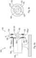
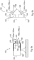
- Figure 4 shows the sensor arrangement 105 from Fig.1 again in connection with the machine 100 in a) side view and b) the carrier 135 in front view.
- Fig.4 shows a variant in which a total of four flow elements are mounted on the carrier 135 125 are present. These extend in the circumferential direction to the rotation axis 155.
- the carrier 135 has a central hole for mounting on the rotor 185 or the corresponding shaft of the motor or machine 100.
- the flux element 125 reduces the inductance La-i of the coil 160a-i when it is "above” it or slides over it.
- the flux element can also be referred to here as a "copper activator" in the periphery of the non-conductive disk or the carrier 135.
- a support part 190 for the flat coils 60a-i or a circuit board 195, symbolically indicated here, on which they are mounted, is attached to the stator 180 or a motor housing, for example with screws or rivets.
- the motor or machine 100 is attached to a solid mounting base via a mounting column (not explained in more detail).
- Fig. 5a shows an alternative sensor arrangement 105.
- the surface 120 is a straight circular cylinder shell around the rotation axis 155.
- the flat coils 160a-i are also sections of the circular cylinder shell.
- the coils are basically as in Fig.1 shaped, ie in one plane “trapezoidal", but “rolled up” or “bent” on the circular cylinder shell.
- three identical coil groups are arranged, each with three flat coils (as in Fig.1 ) is present.
- Each of the coil groups extends again by rotation angle ranges Wa-c of 120° each in the circumferential direction around the rotation axis 155.
- the widths B (now measured in the axial direction) of the flat coils 160a-i increase or decrease in the circumferential direction in a strictly monotonous manner.
- the flux element 125 is accommodated in a cylindrical carrier 135 which is firmly attached to the rotor 185.
- the flat coils 160a-i together occupy a vertical circular cylinder shell.
- Figure 5b shows another variant of a sensor arrangement 125, in principle according to Fig. 5a
- the flux element 125 is designed with a circumferentially sinusoidal or sinusoidally changing property 175, namely its width B.
- the flat coils 160a-i each have a constant width B here.
- Figure 6a shows (optional, therefore not specifically shown) the sensor arrangement 105 from Fig. 5a,b , installed in the machine 100 according to Fig. 4a .
- the carrier 135 is a thick PVC/plastic/polymer ring for attaching the activator or flow element 125 on the motor shaft or the rotor 180.
- the inductive sensors or flat coils 160a-i are multi-turn/multi-level flat coils.
- a distance d denotes in Figures 4a and 6a the distance between sensors (flat coils 160) and activator (flux element 125).
- Figure 6b shows an alternative shape, namely a cone shape for flat coils 160, flux elements 125, carrier 135 and support part 190.
- the embodiment is a cone shape and thus an "intermediate form" between the "disk shape” ( Fig.1 ) and the “cylindrical shape” ( Fig.5 Otherwise, the explanations above apply accordingly.
- Figure 7 shows an example of a coil group 165a with only two flat coils 160a,b, which are suitable for the embodiments of the Figures 5a, b
- the widths B in the axial direction
- the widths B are measured in opposite directions, falling and rising in a strictly monotonous manner in the circumferential direction.
- a first level of the flat coils with a large number of turns can be seen.
- Further levels are connected here invisibly "under" the paper level.
- Figure 8 shows in a plan view in the direction of the axis of rotation 155 an alternative embodiment of a sensor arrangement, in principle corresponding Fig.1
- a flat sensor arrangement made up of six square coils and a rhombus-shaped flux element was "bent” or “unrolled” into a circular shape.
- Each of the six coil groups 165a-f has a single flat coil 160a-f.
- the corresponding flat output sensor arrangement is made up of Figure 1 in the document " AK Palit, 'Frequency Response Modeling of Inductive Position Sensor with Finite Element Tools', Proceedings of the 2014 COMSOL Conference in Cambridge, https://www.comsol.com/ paper/ download/ 199331/ palit_paper.pdf, accessed on December 5, 2018 " known.
Landscapes
- Physics & Mathematics (AREA)
- General Physics & Mathematics (AREA)
- Transmission And Conversion Of Sensor Element Output (AREA)
Description
Die Erfindung betrifft die Erfassung eines Drehwinkels, insbesondere für eine elektrische Maschine.The invention relates to the detection of an angle of rotation, in particular for an electrical machine.
Zum Beispiel im Rahmen der Elektromobilität werden elektrische Maschinen (rotierende Elektromotoren/Generatoren) in Fahrzeugen benötigt. In vielen Fällen ist hierbei eine Drehwinkel-Erfassung für die elektrische Maschine (Drehwinkel eines Rotors gegenüber einem Stator) gewünscht bzw. notwendig.For example, in the context of electromobility, electrical machines (rotating electric motors/generators) are required in vehicles. In many cases, angle of rotation detection for the electrical machine (angle of rotation of a rotor relative to a stator) is desired or necessary.
Aus "Sumida Press Release, 'SUMIDA CORPORATION introduces Inductive RotorPosition Sensor to Hybrid Electric Vehicles Market', https://www.sumida.com/ userfiles/ NEWS_EVENTS/ PRODUCTS/ 100420_RotorPositionSensor/ 20100420_E.pdf, abgerufen am 30.11.2018" ist z.B. ein induktiver Rotorpositionssensor bekannt.For example, an inductive rotor position sensor is known from "Sumida Press Release, 'SUMIDA CORPORATION introduces Inductive RotorPosition Sensor to Hybrid Electric Vehicles Market', https://www.sumida.com/ userfiles/ NEWS_EVENTS/ PRODUCTS/ 100420_RotorPositionSensor/ 20100420_E.pdf, accessed on November 30, 2018".
Aus der
Aus der
Aus der
Aus der
Der Erfindung liegt die Aufgabe zugrunde, die induktive Drehwinkelerfassung zu verbessern.The invention is based on the object of improving the inductive angle of rotation detection.
Die Aufgabe wird gelöst durch eine Sensoranordnung zur Erfassung eines Drehwinkels eines Flusselements, das entlang einer Kreisbahn um eine Drehachse drehbar bzw. rotierbar ist. Bevorzugte oder vorteilhafte Ausführungsformen der Erfindung sowie anderer Erfindungskategorien ergeben sich aus den weiteren Ansprüchen, der nachfolgenden Beschreibung sowie den beigefügten Figuren.The object is achieved by a sensor arrangement for detecting an angle of rotation of a flow element that can rotate or rotate along a circular path about an axis of rotation. Preferred or advantageous embodiments of the invention and other categories of invention emerge from the further claims, the following description and the attached figures.
Die Sensoranordnung enthält mindestens ein, insbesondere ein, zwei, drei oder vier Flusselemente. Das Flusselement weist insbesondere einen Radialabstand zur Drehachse auf, der ungleich Null ist und/oder ist ein passives Flusselement. Das Flusselement ist insbesondere fest auf einem Träger montiert, wobei dann der gesamte Träger zusammen mit dem Flusselement um die Drehachse drehbar ist. Der Träger kann Teil der Sensoranordnung sein. Die Sensoranordnung dient dann auch zur Bestimmung eines aktuellen Drehwinkels des Trägers um die Drehachse.The sensor arrangement contains at least one, in particular one, two, three or four flow elements. The flow element in particular has a radial distance from the axis of rotation that is not equal to zero and/or is a passive flow element. The flow element is in particular firmly mounted on a carrier, whereby the entire carrier can then be rotated about the axis of rotation together with the flow element. The carrier can be part of the sensor arrangement. The sensor arrangement then also serves to determine a current angle of rotation of the carrier about the axis of rotation.
Die Sensoranordnung enthält außerdem mindestens eine, insbesondere eine, zwei, drei, vier, fünf oder sechs, Spulengruppen. Jede der Spulengruppen enthält jeweils mindestens eine, insbesondere eine, zwei oder drei Flachspulen. Insgesamt sind mindestens zwei Flachspulen vorhanden. Die Flachspulen erstrecken sich jeweils entlang einer Fläche. Die Fläche umgibt die Drehachse konzentrisch. Die Fläche verläuft parallel entlang der Kreisbahn. Alle Flachspulen einer Spulengruppe - und damit auch die gesamte Spulengruppe - erstrecken sich jeweils über denselben Drehwinkelbereich bezüglich der Drehachse. Insbesondere enthält die Sensoranordnung mindestens zwei Spulengruppen mit jeweils mindestens zwei Flachspulen. Der Zusatz "Flach" in "Flachspule" bezieht sich hier auf die Fläche, d.h. die Flachspulen erstrecken sich flächig oder flächenhaft in der Fläche.The sensor arrangement also contains at least one, in particular one, two, three, four, five or six, coil groups. Each of the coil groups contains at least one, in particular one, two or three flat coils. In total, there are at least two flat coils. The flat coils each extend along a surface. The surface surrounds the axis of rotation concentrically. The surface runs parallel along the circular path. All flat coils in a coil group - and thus also the entire coil group - each extend over the same angle of rotation range with respect to the axis of rotation. In particular, the sensor arrangement contains at least two coil groups, each with at least two flat coils. The addition "flat" in "flat coil" refers here to the surface, i.e. the flat coils extend flatly or areally in the surface.
Die Flachspulen sind derart geformt, dass eine aktuelle Induktivität jeder Flachspule von dem aktuellen Drehwinkel des Flusselements bezüglich der Drehachse, d.h. seiner Umfangsposition entlang der Kreisbahn, abhängig ist.The flat coils are shaped in such a way that a current inductance of each flat coil depends on the current angle of rotation of the flux element with respect to the axis of rotation, i.e. its circumferential position along the circular path.
Die Sensoranordnung enthält weiterhin eine Auswerteeinrichtung. Diese ist - zum Beispiel durch Festverdrahtung oder Programmierung - dazu eingerichtet, für jede der Flachspulen deren aktuelle Induktivität zu einem bestimmten Zeitpunkt zu ermitteln. Weiterhin ist sie dazu eingerichtet, einen aktuellen jeweiligen Einzeldrehwinkel des Flusselements anhand der ermittelten Induktivität der jeweiligen Flachspule zu bestimmen. Weiterhin ist sie dazu eingerichtet, den Drehwinkel des Flusselements auf der Basis wenigstens zweier übereinstimmender Einzeldrehwinkel zweier verschiedener Flachspulen bereitzustellen. Die Einzeldrehwinkel müssen dabei im Rahmen eines akzeptablen Fehlermaßes übereinstimmen. Alternativ wird eine Fehlermaßnahme ergriffen, zum Beispiel eine Fehlermeldung ausgegeben, wenn nicht wenigstens zwei Einzeldrehwinkel entsprechend übereinstimmen.The sensor arrangement also contains an evaluation device. This is designed - for example by hardwiring or programming - to determine the current inductance of each of the flat coils at a specific time. It is also designed to determine a current individual angle of rotation of the flux element based on the determined inductance of the respective flat coil. It is also designed to provide the angle of rotation of the flux element on the basis of at least two matching individual angles of rotation of two different flat coils. The individual angles of rotation must be within an acceptable range. Alternatively, an error measure is taken, for example an error message is issued if at least two individual angles of rotation do not match accordingly.
Insbesondere enthält mindestens eine der Spulengruppen eine (dritte) oder noch mehr weitere Flachspulen. Diese führen dann weitere Redundanz in die Sensoranordnung bzw. Spulengruppe ein, da weitere Einzeldrehwinkel für die gleiche Relativlage von Flusselement und Spulengruppe ermittelt werden und zur Auswertung zur Verfügung stehen.In particular, at least one of the coil groups contains a (third) or more additional flat coils. These then introduce further redundancy into the sensor arrangement or coil group, since additional individual angles of rotation are determined for the same relative position of the flux element and coil group and are available for evaluation.
Insbesondere beträgt die Summe aller Drehwinkelbereiche mindestens 360°, sodass alle möglichen Drehwinkel des Flusselements um die Drehachse erfasst werden können.In particular, the sum of all rotation angle ranges is at least 360°, so that all possible rotation angles of the flow element around the rotation axis can be recorded.
Die Flachspulen sind also derart geformt, dass eine aktuelle Induktivität jeder Flachspule von einer Position des Flusselements entlang der Kreisbahn abhängig ist. Mit anderen Worten können unterschiedliche zu ermittelnde Drehwinkel anhand der ermittelten Induktivitäten eindeutig unterschieden werden.The flat coils are shaped in such a way that the current inductance of each flat coil depends on the position of the flux element along the circular path. In other words, different angles of rotation can be clearly distinguished based on the determined inductances.
Mit der Sensoranordnung können praktisch beliebig viele Drehwinkel des Flusselements bestimmt werden. Es ist nicht notwendig, einem zu bestimmenden Drehwinkel eine Flachspule zuzuordnen. Eine Anzahl und/oder Lage von zu bestimmenden Drehwinkeln kann frei gewählt und zu einem beliebigen Zeitpunkt verändert werden. Die Sensoranordnung kann flexibel für verschiedene Anwendungsfälle eingesetzt werden und zu erkennende Drehwinkel können bei Bedarf kalibriert werden. Die Sensoranordnung kann beispielsweise für eine elektrische Maschine zur Bestimmung des aktuellen Drehwinkels des Rotors gegenüber einem Stator eingesetzt werden.The sensor arrangement can be used to determine practically any number of angles of rotation of the flux element. It is not necessary to assign a flat coil to a rotation angle to be determined. The number and/or position of rotation angles to be determined can be freely selected and changed at any time. The sensor arrangement can be used flexibly for various applications and the angles of rotation to be detected can be calibrated if necessary. The sensor arrangement can be used, for example, for an electrical machine to determine the current angle of rotation of the rotor relative to a stator.
Durch Bestimmung des Drehwinkels des Flusselements mittels dreier Flachspulen in einer Spulengruppe kann eine Redundanz geschaffen sein, die einen Betrieb der Sensoranordnung bzw. eine korrekte Erkennung des Drehwinkels auch dann erlaubt, wenn eine der Flachspulen ausfallen sollte, beispielsweise aufgrund eines Kurzschlusses oder einer Unterbrechung des Spulendrahts.By determining the angle of rotation of the flux element by means of three flat coils in a coil group, a redundancy can be created that allows operation of the sensor arrangement or correct detection of the angle of rotation even if one of the flat coils should fail, for example due to a short circuit or an interruption of the coil wire.
Ein Abstand zwischen der Kreisbahn und Fläche ist weiter bevorzugt konstant. Die Kreisbahn kann auch bevorzugt der Fläche mit konstantem Abstand folgen.A distance between the circular path and the surface is further preferably constant. The circular path can also preferably follow the surface with a constant distance.
Die Erfindung kann insbesondere zur Rotorpositionserkennung in elektrischen Maschinen bzw. Motoren/Generatoren eingesetzt werden, insbesondere im Bereich der Elektromobilität.The invention can be used in particular for rotor position detection in electrical machines or motors/generators, in particular in the field of electromobility.
Die vorliegende Erfindung nutzt mindestens zwei, insbesondere drei, Flachspulen, die - insbesondere in Radialrichtung, in Axialrichtung oder in einer kombinierten Radial-Axialrichtung - bezüglich der Drehachse nebeneinander angeordnet sind. Bezüglich ihrer Länge sind sie in Umfangsrichtung, kreissegment- bzw. bogenförmig in gleicher oder ähnlicher Weise um die Drehachse herum geformt bzw. gebogenThe present invention uses at least two, in particular three, flat coils which are arranged next to one another with respect to the axis of rotation - in particular in the radial direction, in the axial direction or in a combined radial-axial direction. In terms of their length, they are shaped or bent in the same or similar way around the axis of rotation in the circumferential direction, in the shape of a circular segment or arc.
Die Erfindung beruht unter anderem auf der Erkenntnis, dass die genaue Messung des Drehwinkels eines Rotors sehr wichtig für einen Elektromotor basierend auf Elektromobilitätsprojekten ist. Aufgrund eines großen Hindernisses auf einer Straße ist es vorstellbar, dass Räder eines Elektromobils sich nicht vorwärts bewegen können. In der Folge entsteht für den Elektromotor ein Zustand "blockierter Rotor". Dieser Zustand kann mit einem Drehwinkel-Positionssensor für den Rotor erkannt werden. Ansonsten könnte in einem Zustand "blockierter Rotor" eine MOSFET basierte H-Brücke oder der Motor abbrennen.The invention is based, among other things, on the realization that the precise measurement of the angle of rotation of a rotor is very important for an electric motor based on electromobility projects. Due to a large obstacle on a road, it is conceivable that the wheels of an electric vehicle cannot move forward. As a result, a "blocked rotor" state arises for the electric motor. This state can be detected with a rotation angle position sensor for the rotor. Otherwise, a MOSFET-based H-bridge or the motor could burn out in a "blocked rotor" state.
Dank der Erfindung kann die korrekte Drehwinkel-Position des Rotor ermittelt und eine geeignete Maßnahme ergriffen werden, um die oben genannte Situation zu verhindern, d.h. die Zerstörung der H-Brücke oder des Motors selbst durch einen hohen Stromfluss vermieden werden.Thanks to the invention, the correct rotation angle position of the rotor can be determined and appropriate action can be taken to prevent the above-mentioned situation, i.e. to avoid the destruction of the H-bridge or the motor itself due to a high current flow.
Gemäß der Erfindung werden zwei oder drei (in einer Ebene) trapezoide Flachspulen aus einer ebenen in eine gebogene Form überführt, sodass sie sich in die konzentrische Fläche um die Drehachse einfügen. Die Flachspulen sind hierbei insbesondere direkt auf einer Leiterplatte gedruckt. Die Leiterplatte kann dabei intern an einem stationären bzw. festen Teil eines Elektromotors, zum Beispiel am Stator, befestigt werden.According to the invention, two or three (in one plane) trapezoidal flat coils are converted from a flat to a curved shape so that they fit into the concentric surface around the axis of rotation. The flat coils are in particular printed directly on a circuit board. The circuit board can be attached internally to a stationary or fixed part of an electric motor, for example to the stator.
Insbesondere wird weiterhin eine dünne leitfähige Platte (Flusselement) aus Kupfer/Aluminium, insbesondere mit einer speziellen Gestalt bzw. Kontur, auf einer nicht leitenden Scheibe oder einem Zylinder (Träger) befestigt und fest an die rotierende Rotorwelle befestigt. In der Folge gleitet die Platte über die Flachspulen hinweg bei Drehung um die Drehachse. Diese Kombination aus Flachspulen und Flusselement (Kupferaktivator-Element) bildet die Basis eines induktiven Drehwinkelsensors (IRPS, Inductive Rotor Position Sensor). Der Drehwinkel des Rotors wird basierend auf den oben genannten Signalen berechnet. Eine Spulengruppe aus drei solchen trapezoiden Flachspulen (gebogen in rotatorische Form) deckt insbesondere wenigstens 60°, höchstens 90° Drehwinkelbereich um die Drehachse ab. Daher werden für die Messung eines vollen Drehbereiches (360°) der Rotorposition (Drehwinkel) wenigstens vier Spulengruppen (4 × 90° = 360°) oder höchstens sechs Spulengruppen (6 × 60° = 360°) zweier oder dreier solcher trapezoider Flachspulen von rotatorischer Form benötigt, wenn sich diese in Umfangsrichtung um die Drehachse nicht überlappen und lückenlos aneinander anschließen.In particular, a thin conductive plate (flux element) made of copper/aluminum, in particular with a special shape or contour, is attached to a non-conductive disk or cylinder (carrier) and firmly attached to the rotating rotor shaft. The plate then slides over the flat coils when rotating around the axis of rotation. This combination of flat coils and flux element (copper activator element) forms the basis of an inductive rotation angle sensor (IRPS, Inductive Rotor Position Sensor). The rotation angle of the rotor is calculated based on the above-mentioned signals. A coil group made up of three such trapezoidal flat coils (bent into a rotary shape) covers in particular at least 60°, at most 90° rotation angle range around the axis of rotation. Therefore, to measure a full rotation range (360°) of the rotor position (angle of rotation), at least four coil groups (4 × 90° = 360°) or a maximum of six coil groups (6 × 60° = 360°) of two or three such trapezoidal flat coils of rotary shape are required, provided that they do not overlap in the circumferential direction around the axis of rotation and are connected to one another without gaps.
In einer bevorzugten Ausführungsform enthält die Sensoranordnung mindestens zwei Spulengruppen. Mindestens zwei der Spulengruppen erstrecken sich in Umfangsrichtung um die Drehachse über unterschiedliche Drehwinkelbereiche. Die Drehwinkelbereiche überlappen sich in Umfangsrichtung zumindest nicht vollständig, insbesondere überhaupt nicht. Insbesondere sind mindestens zwei der Drehwinkelbereiche gleich groß (in Umfangsrichtung). Insbesondere für eine Rundumerfassung um die Drehachse müssen so einzelne Flachspulen nur einen bestimmten Drehwinkelbereich, nicht jedoch den vollen Umfang überdecken und können somit einfacher ausgeführt werden.In a preferred embodiment, the sensor arrangement contains at least two coil groups. At least two of the coil groups extend in the circumferential direction around the axis of rotation over different angle of rotation ranges. The angle of rotation ranges at least do not overlap completely in the circumferential direction, in particular not at all. In particular, at least two of the angle of rotation ranges are the same size (in the circumferential direction). In particular for all-round detection around the axis of rotation, individual flat coils only have to cover a certain angle of rotation range, but not the entire circumference, and can therefore be designed more simply.
In einer bevorzugten Variante dieser Ausführungsform überlappen mindestens zwei, insbesondere alle, der Drehwinkelbereiche nicht und schließen in Umfangsrichtung lückenlos aneinander an. So kann mit Flachspulen, welche sich in Umfangsrichtung über einen vergleichsweise kleinen einzelnen Drehwinkelbereich erstrecken, ein möglichst großer gesamter Drehwinkelbereich der aneinander anschließenden einzelnen Drehwinkelbereiche erfasst werden. Insbesondere sind vier Drehwinkelbereiche zu je 90° oder sechs Drehwinkelbereiche zu je 60° vorgesehen, um jeweils eine 360°-Drehwinkelerfassung zu realisieren.In a preferred variant of this embodiment, at least two, in particular all, of the angle of rotation ranges do not overlap and are connected to one another without gaps in the circumferential direction. In this way, with flat coils that extend in the circumferential direction over a comparatively small individual angle of rotation range, the largest possible total angle of rotation range of the individual angle of rotation ranges that adjoin one another can be recorded. In particular, four angle of rotation ranges of 90° each are or six rotation angle ranges of 60° each are provided in order to realize a 360° rotation angle detection.
In einer bevorzugten Ausführungsform ist die Fläche eben und erstreckt sich quer zur Drehachse. Die Fläche beschreibt damit also eine Kreisringform. Alternativ weist die Fläche eine Konusform oder eine Kreiskegelform oder eine Mantelflächenform eines - insbesondere geraden - Kreiszylinders um die Drehachse auf. Entsprechende Flächen und damit auch Flachspulen, die sich entlang dieser Flächen erstrecken, lassen sich besonders einfach realisieren.In a preferred embodiment, the surface is flat and extends transversely to the axis of rotation. The surface therefore describes a circular ring shape. Alternatively, the surface has a conical shape or a circular conical shape or a lateral surface shape of a - in particular straight - circular cylinder around the axis of rotation. Corresponding surfaces and thus also flat coils that extend along these surfaces can be implemented particularly easily.
In einer bevorzugten Ausführungsform weist das Flusselement eine sinusförmige Eigenschaft entlang der Kreisbahn auf. Die Eigenschaft bezieht sich insbesondere auf die Form, das Material, die Dicke (Radial- oder Axialrichtung oder Kombination), die Breite (Axial- oder Radialrichtung oder Kombination) des Flusselements. Die Flachspule kann in diesem Fall insbesondere mit homogenen bzw. gleichbleibenden Eigenschaften (Breite, Dicke, Material, Windungszahl, Geometrie, usw.) - insbesondere in Umfangsrichtung - und damit besonders einfach ausgeführt sein.In a preferred embodiment, the flux element has a sinusoidal property along the circular path. The property relates in particular to the shape, the material, the thickness (radial or axial direction or combination), the width (axial or radial direction or combination) of the flux element. In this case, the flat coil can in particular be designed with homogeneous or consistent properties (width, thickness, material, number of turns, geometry, etc.) - in particular in the circumferential direction - and thus be particularly simple.
Gemäß der Erfindung ist mindestens eine der Flachspulen derart geformt, dass jeweils die Größe eines vom Flusselement abgedeckten Bereichs einer Flachspule in der Fläche vom aktuellen Drehwinkel des Flusselements, also von der Position des Flusselements entlang der Kreisbahn, abhängig ist. Der durch das Flusselement abgedeckte Bereich kann anhand einer Projektion des Flusselements auf die Fläche bzw. die Flachspule in Richtung der Normalen der Fläche bestimmt werden. Die Projektionsrichtung ist hierbei insbesondere in Richtung einer senkrechten zur Kreisbahn auf die Flachspule hingerichtet. Bevorzugt ist der gesamte Bereich, den das Flusselement über seine verschiedenen Drehwinkel in der Fläche abdecken kann, durch jeweils mindestens eine der Flachspulen abgedeckt. Je größer der vom Flusselement abgedeckte Bereich einer Flachspule ist, desto stärker kann sein Einfluss auf deren Induktivität sein. Durch Verknüpfung des abgedeckten Bereichs einer Flachspule mit dem Drehwinkel kann die Induktivität der Flachspule vom Drehwinkel des Flusselements abhängig sein, sodass der Drehwinkel auf der Basis der Induktion bestimmt werden kann.According to the invention, at least one of the flat coils is shaped in such a way that the size of an area of a flat coil in the surface covered by the flux element depends on the current angle of rotation of the flux element, i.e. on the position of the flux element along the circular path. The area covered by the flux element can be determined based on a projection of the flux element onto the surface or the flat coil in the direction of the normal of the surface. The projection direction is directed in particular in the direction perpendicular to the circular path on the flat coil. Preferably, the entire area that the flux element can cover in the surface over its various angles of rotation is covered by at least one of the flat coils. The larger the area of a flat coil covered by the flux element, the stronger its influence on its inductance can be. By linking the covered area of a flat coil to the angle of rotation, the inductance of the flat coil can depend on the angle of rotation of the flux element, so that the angle of rotation can be determined on the basis of the induction.
Die Kreisbahn erstreckt sich gemäß der Erfindung zwischen einem Startwinkel und einem Endwinkel. Eine Breite einer ersten - und insbesondere einer dritten Flachspule, falls eine solche vorhanden ist - mindestens einer Spulengruppe nimmt dabei quer zur Kreisbahn vom Startwinkel aus zum Endwinkel hin ab, während eine Breite einer zweiten Flachspule der selben Spulengruppe in der gleichen Richtung vom Startwinkel aus zum Endwinkel hin zunimmt. Dadurch können die Flachspulen verbessert kompakt angeordnet werden. Die erste und die dritte Flachspule können für den oben genannten Fall insbesondere so beschaffen sein, dass ihre Induktivitäten einander bei jedem Drehwinkel des Flusselements entsprechen.According to the invention, the circular path extends between a starting angle and an end angle. A width of a first - and in particular a third flat coil, if one is present - of at least one coil group decreases transversely to the circular path from the starting angle to the end angle, while a width of a second flat coil of the same coil group increases in the same direction from the starting angle to the end angle. This allows the flat coils to be arranged more compactly. In the above-mentioned case, the first and third flat coils can in particular be designed such that their inductances correspond to one another at every angle of rotation of the flux element.
Für mindestens eine der Spulengruppen, die hier mindestens drei Flachspulen enthält, liegt die zweite Flachspule in einer Richtung quer zur Kreisbahn zwischen der ersten und der dritten Flachspule. Dadurch kann eine besonders kompakte Bauform der Flachspulen realisiert werden. Eine gegenseitige Beeinflussung benachbarter Flachspulen kann außerdem verringert sein.For at least one of the coil groups, which here contains at least three flat coils, the second flat coil is located in a direction transverse to the circular path between the first and third flat coils. This allows a particularly compact design of the flat coils to be achieved. Mutual influences between neighboring flat coils can also be reduced.
In einer bevorzugten Ausführungsform nehmen die Flachspulen mindestens einer der Spulengruppen zusammen ein Kreisringsegment oder einen Konusmantel oder einen senkrechten Kreiszylindermantel der Fläche ein. Dadurch können die Flachspulen kompakt aufgebaut sein und gemeinsam leicht angeordnet oder verbaut werden. Das Flusselement kann dabei insbesondere eine (im Sinne des "Aufwickelns" bzw. "Biegens" entlang der bzw. parallel zur Fläche) rechteckige Form aufweisen, wobei Breiten des Flusselements und der Fläche der Flachspulen gleich sein können und eine Länge des Flusselements in Richtung der Kreisbahn bevorzugt kleiner als die Länge der Fläche der Flachspulen ist.In a preferred embodiment, the flat coils of at least one of the coil groups together take up a circular ring segment or a conical shell or a vertical circular cylinder shell of the surface. This allows the flat coils to be compactly constructed and easy to arrange or install together. The flux element can in particular have a rectangular shape (in the sense of "winding up" or "bending" along or parallel to the surface), whereby the widths of the flux element and the surface of the flat coils can be the same and a length of the flux element in the direction of the circular path is preferably smaller than the length of the surface of the flat coils.
Eine Flachspule umfasst üblicherweise mehrere Windungen, die in der Fläche liegen. Eine innerste Windung kann die Form eines auf die Fläche "aufgerollten" bzw. "gebogenen" ursprünglich ebenen Trapezoids oder Dreiecks haben und weiter außen liegende Windungen können jeweils konstanten Abstand zur nächsten weiter innen liegenden Windung aufweisen. Dadurch können alle Windungen außer der innersten jeweils die Form eines auf die Fläche aufgerollten bzw. gebogenen Dreiecks oder Trapezoids aufweisen. Man kann auch allgemein von einer trapezförmigen Flachspule sprechen, wobei ein Dreieck eine Sonderform des Trapezoids darstellt, bei der zwei benachbarte Ecken zu einer einzigen Ecke zusammenfallen.A flat coil usually comprises several turns that lie in the surface. An innermost turn can have the shape of an originally flat trapezoid or triangle that is "rolled up" or "bent" onto the surface, and turns further out can each have a constant distance to the next turn further in. This means that all turns except the innermost can each have the shape of a triangle or trapezoid that is rolled up or bent onto the surface. One can also generally speak of a trapezoidal flat coil. A triangle is a special form of the trapezoid in which two adjacent corners coincide to form a single corner.
In einer Ausführungsform mit Spulengruppe mit mindestens drei Flachspulen haben die innersten Windungen der ersten und der dritten Flachspule jeweils die Form eines auf die Fläche aufgerollten bzw. gebogenen rechtwinkligen Trapezes und die innerste Windung der zweiten Flachspule hat die Form eines auf die Fläche aufgerollten bzw. gebogenen ursprünglich in einer Ebene gleichwinkligen Trapezes. Die äußeren Windungen der ersten und der dritten Flachspule haben dann im Wesentlichen jeweils die Form eines entsprechend gebogenen rechtwinkligen Trapezes und die äußeren Windungen der zweiten Flachspule die eines entsprechend gebogenen gleichschenkligen, symmetrischen Trapezes.In an embodiment with a coil group with at least three flat coils, the innermost turns of the first and third flat coils each have the shape of a right-angled trapezoid rolled up or bent onto the surface, and the innermost turn of the second flat coil has the shape of a trapezoid rolled up or bent onto the surface and originally equiangular in one plane. The outer turns of the first and third flat coils then essentially each have the shape of a correspondingly bent right-angled trapezoid, and the outer turns of the second flat coil have the shape of a correspondingly bent isosceles, symmetrical trapezoid.
In einer bevorzugten Ausführungsform verlaufen die Breiten der Flachspulen entlang der Kreisbahn jeweils streng monoton. Dadurch können sich die Induktivitäten der Flachspulen auch streng monoton über die Position des Flusselements entlang der Kreisbahn (Drehwinkel) entwickeln. Eine eindeutige Bestimmung der Position des Flusselements auf der Basis der Induktivität einer Flachspule kann dadurch ermöglicht sein.In a preferred embodiment, the widths of the flat coils are strictly monotonous along the circular path. This allows the inductances of the flat coils to develop strictly monotonously over the position of the flux element along the circular path (angle of rotation). This can enable the position of the flux element to be clearly determined on the basis of the inductance of a flat coil.
In einer bevorzugten Ausführungsform umfasst mindestens eine der Flachspulen mehrere Ebenen. Die Ebenen können entlang einer Abstandsrichtung der Kreisbahn zur Fläche angeordnet sein. Praktisch kann eine Flachspule als Print-Spule in Form einer Leiterbahn auf einer Platine gebildet werden. Um mehrere Ebenen zu umfassen, können Spulen auf mehreren Lagen der Platine gebildet und elektrisch miteinander verschaltet werden, um eine Flachspule zu bilden. Dabei weisen die Spulen auf den verschiedenen Lagen üblicherweise gleiche Formen, Flächen und Windungsrichtungen auf.In a preferred embodiment, at least one of the flat coils comprises several levels. The levels can be arranged along a distance direction of the circular path from the surface. In practice, a flat coil can be formed as a printed coil in the form of a conductor track on a circuit board. In order to comprise several levels, coils can be formed on several layers of the circuit board and electrically connected to one another to form a flat coil. The coils on the different layers usually have the same shapes, areas and winding directions.
Dabei können Spulen auch auf beide Seiten der Lagen angebracht werden, z.B. können bei einer 4-lagigen Flachspule die einzelnen Spulenebenen auf beiden Seiten einer (4-lagigen) Leiterplatte angebracht werden. Ein jeweiliges (also insgesamt zwei) Flusselement kann dann auf beiden Seiten der Leiterplatte vorhanden sein, um die Flachspule von beiden Seiten zu beeinflussen. Die beeinflussende Wirkung wird so verstärkt. Insbesondere kann dann ein U-förmiges Flusselement einen Rand einer Trägerscheibe beidseitig umgreifen, an deren Außenumfang die Spulengruppen angebracht sind.Coils can also be attached to both sides of the layers, e.g. in the case of a 4-layer flat coil, the individual coil levels can be attached to both sides of a (4-layer) circuit board. A respective (i.e. two in total) flux element can then be present on both sides of the circuit board in order to Flat coil can be influenced from both sides. The influencing effect is thus increased. In particular, a U-shaped flux element can then encompass both sides of an edge of a carrier disk, on whose outer circumference the coil groups are attached.
In einer bevorzugten Ausführungsform enthält das Flusselement ein elektrisch leitfähiges Element, das sich insbesondere parallel zur Fläche erstreckt. Das leitfähige Element kann die Induktivität einer Flachspule, in deren elektromagnetischem Feld es sich befindet, verringern und so als Dämpfungselement wirken. Dabei nimmt das Flusselement Energie aus dem elektromagnetischen Feld auf und bildet Wirbelströme im elektrisch leitfähigen Material.In a preferred embodiment, the flux element contains an electrically conductive element that extends in particular parallel to the surface. The conductive element can reduce the inductance of a flat coil in whose electromagnetic field it is located and thus act as a damping element. The flux element absorbs energy from the electromagnetic field and forms eddy currents in the electrically conductive material.
In einer anderen Ausführungsform kann ein Flusselement verwendet werden, das die Induktivität einer Flachspule erhöht, wenn es sich in ihrem elektromagnetischen Feld befindet. Das Flusselement ist dabei bevorzugt aus einem elektrisch schlecht leitenden, ferrimagnetischen Material wie Ferrit oder Eisen gefertigt.In another embodiment, a flux element can be used that increases the inductance of a flat coil when it is in its electromagnetic field. The flux element is preferably made of a poorly electrically conductive, ferrimagnetic material such as ferrite or iron.
Die Aufgabe der Erfindung wird auch gelöst durch eine elektrische Maschine gemäß Patentanspruch 10. Die Maschine enthält einen Stator und mit einem um eine Drehachse relativ zum Stator drehbaren Rotor und eine Sensoranordnung nach einem der vorhergehenden Ansprüche, wobei die Drehachse der Sensoranordnung die Drehachse der Maschine ist und das Flusselement drehfest mit dem Rotor gekoppelt ist und die Spulengruppen drehfest mit dem Stator gekoppelt sind. Auch eine umgekehrte Variante (Spulengruppen am Rotor, Flusselement am Stator) ist möglich.The object of the invention is also achieved by an electrical machine according to claim 10. The machine contains a stator and a rotor that can rotate about an axis of rotation relative to the stator and a sensor arrangement according to one of the preceding claims, wherein the axis of rotation of the sensor arrangement is the axis of rotation of the machine and the flux element is coupled to the rotor in a rotationally fixed manner and the coil groups are coupled to the stator in a rotationally fixed manner. A reverse variant (coil groups on the rotor, flux element on the stator) is also possible.
Die Maschine und zumindest ein Teil deren Ausführungsformen sowie die jeweiligen Vorteile wurden sinngemäß bereits im Zusammenhang mit der erfindungsgemäßen Sensoranordnung erläutert.The machine and at least some of its embodiments as well as the respective advantages have already been explained in connection with the sensor arrangement according to the invention.
In einer bevorzugten Ausführungsform enthält die Maschine oder die Sensoranordnung einen elektrisch nicht leitenden, am Rotor befestigten Träger. Die Flusselemente sind auf dem Träger montiert. Der Träger ist insbesondere eine Scheibe oder ein gerader Kreiszylinder bezüglich der Drehachse.In a preferred embodiment, the machine or the sensor arrangement contains an electrically non-conductive carrier attached to the rotor. The flux elements are mounted on the carrier. The carrier is in particular a disk or a right circular cylinder with respect to the axis of rotation.
Der Aspekt eines solchen Trägers und zumindest ein Teil solcher Ausführungsformen sowie die jeweiligen Vorteile wurden sinngemäß bereits im Zusammenhang mit der erfindungsgemäßen Sensoranordnung erläutert.The aspect of such a carrier and at least some of such embodiments as well as the respective advantages have already been explained in connection with the sensor arrangement according to the invention.
In Bezug auf die Sensoranordnung kann die Auswerteeinrichtung eine Verarbeitungseinrichtung umfassen, die dazu eingerichtet ist, ein im Folgenden beschriebenes Verfahren ganz oder teilweise auszuführen. Dazu kann die Verarbeitungseinrichtung einen programmierbaren Mikrocomputer oder Mikrocontroller umfassen und das Verfahren kann in Form eines Computerprogrammprodukts mit Programmcodemitteln vorliegen. Das Computerprogrammprodukt kann auch auf einem computerlesbaren Datenträger abgespeichert sein. Merkmale oder Vorteile des Verfahrens können auf die Sensoranordnung übertragen werden oder umgekehrt.With regard to the sensor arrangement, the evaluation device can comprise a processing device which is designed to carry out a method described below in whole or in part. For this purpose, the processing device can comprise a programmable microcomputer or microcontroller and the method can be in the form of a computer program product with program code means. The computer program product can also be stored on a computer-readable data carrier. Features or advantages of the method can be transferred to the sensor arrangement or vice versa.
Die Aufgabe der Erfindung wird daher auch gelöst durch ein Verfahren gemäß Anspruch 12 zur Erfassung eines Drehwinkels eines Flusselements einer erfindungsgemäßen Sensoranordnung oder einer erfindungsgemäßen Maschine. Bei dem Verfahren wird für jede der Flachspulen die aktuelle Induktivität ermittelt. Anschließend wird ein aktueller jeweiliger Einzeldrehwinkel des Flusselements anhand der ermittelten Induktivität der jeweiligen Flachspule bestimmt. Anschließend wird der Drehwinkel des Flusselements auf der Basis wenigstens zweier übereinstimmender Einzeldrehwinkel bereitgestellt.The object of the invention is therefore also achieved by a method according to claim 12 for detecting an angle of rotation of a flux element of a sensor arrangement according to the invention or a machine according to the invention. In the method, the current inductance is determined for each of the flat coils. A current respective individual angle of rotation of the flux element is then determined based on the determined inductance of the respective flat coil. The angle of rotation of the flux element is then provided on the basis of at least two matching individual angles of rotation.
Das Verfahren und zumindest ein Teil dessen Ausführungsformen sowie die jeweiligen Vorteile wurden sinngemäß bereits im Zusammenhang mit der erfindungsgemäßen Sensoranordnung und der erfindungsgemäßen Maschine erläutert.The method and at least some of its embodiments as well as the respective advantages have already been explained in connection with the sensor arrangement according to the invention and the machine according to the invention.
Das Verfahren umfasst also die Schritte des Bestimmens von Induktivitäten der Flachspulen; des Bestimmens von Einzelrehwinkeln des Flusselements jeweils bezüglich einer der bestimmten Induktivitäten bzw. Flachspulen; und des Bereitstellens eines Drehwinkels des Flusselements auf der Basis von wenigstens zwei einander entsprechenden der bestimmten Einzeldrehwinkel. Entsprechen die zwei - oder insbesondere drei oder mehr - bestimmten Einzeldrehwinkel einander, so kann der Drehwinkel des Flusselements auf der Basis aller Einzelrehwinkel bestimmt werden. Einander entsprechende Einzeldrehwinkel weichen üblicherweise aufgrund von Imperfektion bei der Bestimmung leicht voneinander ab. Das Bereitstellen des Drehwinkels kann beispielsweise das Bilden eines Minimums, eines Maximums, eines Mittelwerts der bestimmten Einzeldrehwinkel oder die Auswahl eines der bestimmten Einzeldrehwinkel umfassen, die einer vorbestimmten der zwei oder drei oder mehr Flachspulen zugeordnet ist. Entsprechen nur zwei der Einzeldrehwinkel einander, so kann der Drehwinkel des Flusselements auf der Basis dieser beiden bestimmten Einzeldrehwinkel bestimmt werden. In einer allgemeinen Ausführungsform sind N Flachspulen im Bereich des Flusselements vorgesehen, wobei bevorzugt N > 2 gilt und N weiter bevorzugt ungerade ist. Der Drehwinkel des Flusselements kann dann bezüglich einer Mehrheit einander entsprechender Einzeldrehwinkel bestimmt werden, die jeweils einer der Flachspulen zugeordnet sind. Die Sensoranordnung kann allgemein auch nach Ausfall von N-2 Flachspulen weiter den Drehwinkel des Flusselements bestimmen. Aus Platzgründen und einer zu erwartenden Wahrscheinlichkeit des Ausfalls von mehr als einer Flachspule zur gleichen Zeit wird vorgeschlagen, N=3 (pro Spulengruppe) zu wählen.The method thus comprises the steps of determining inductances of the flat coils; determining individual angles of rotation of the flux element in each case with respect to one of the determined inductances or flat coils; and providing an angle of rotation of the flux element on the basis of at least two of the determined individual angles of rotation that correspond to one another. If the two - or in particular three or more - determined individual angles of rotation correspond to one another, the angle of rotation of the flux element can be determined on the basis of all individual angles of rotation. Corresponding individual angles of rotation usually differ slightly from one another due to imperfections in the determination. Providing the angle of rotation can, for example, comprise forming a minimum, a maximum, an average of the determined individual angles of rotation or selecting one of the determined individual angles of rotation that is assigned to a predetermined one of the two or three or more flat coils. If only two of the individual angles of rotation correspond to one another, the angle of rotation of the flux element can be determined on the basis of these two determined individual angles of rotation. In a general embodiment, N flat coils are provided in the region of the flux element, with N>2 preferably applying and N more preferably being odd. The angle of rotation of the flux element can then be determined with respect to a majority of corresponding individual angles of rotation, each of which is assigned to one of the flat coils. The sensor arrangement can generally continue to determine the angle of rotation of the flux element even after N-2 flat coils have failed. Due to space constraints and an expected probability of failure of more than one flat coil at the same time, it is proposed to choose N=3 (per coil group).
Gemäß der Erfindung enthält die Sensoranordnung mindestens 3 Flachspulen. Eine (für den Fall, dass eine solche vorhanden ist) defekte Flachspule wird erkannt bzw. bestimmt, falls ein auf der Basis ihrer Induktivität bestimmter Einzeldrehwinkel von einander entsprechenden Einzeldrehwinkeln abweicht, die auf der Basis der anderen Flachspulen bestimmt wurden. Insbesondere wird diese Verfahrensvariante innerhalb einer Spulengruppe ausgeführt, die mindestens 3 Flachspulen enthält. Ein Signal oder eine Nachricht, die auf die defekte Flachspule hinweist, kann bereitgestellt werden. Die defekte Flachspule kann vom weiteren Betrieb der Sensoranordnung ausgeschlossen werden. Die Sensoranordnung kann zumindest solange weiter betrieben werden, wie insbesondere innerhalb der betreffenden Spulengruppe keine weitere der Flachspulen als defekt bestimmt wird.According to the invention, the sensor arrangement contains at least 3 flat coils. A defective flat coil (if such a coil is present) is detected or determined if an individual angle of rotation determined on the basis of its inductance deviates from corresponding individual angles of rotation determined on the basis of the other flat coils. In particular, this method variant is carried out within a coil group that contains at least 3 flat coils. A signal or a message indicating the defective flat coil can be provided. The defective flat coil can be excluded from further operation of the sensor arrangement. The sensor arrangement can continue to operate at least as long as no other flat coils are determined to be defective, in particular within the coil group in question.
Weitere Merkmale, Wirkungen und Vorteile der Erfindung ergeben sich aus der nachfolgenden Beschreibung eines bevorzugten Ausführungsbeispiels der Erfindung sowie der beigefügten Figuren. Dabei zeigen, jeweils in einer schematischen Prinzipskizze:
- Figur 1
- eine erfindungsgemäße Sensoranordnung einer Maschine,
- Figur 2
- den Verlauf von Induktivitäten über dem Drehwinkel in der Sensoranordnung aus
Fig. 1 , - Figur 3
- ein Ablaufdiagramm für ein Verfahren zur Ermittlung des Drehwinkels in
Fig. 1 , - Figur 4
- die elektrische Maschine aus
Fig. 1 in a) Seitenansicht und b) eine alternativen Träger mit Flusselementen in Frontalansicht, - Figur 5
- alternative Flachspulen und Flusselemente in Zylinderform a) sinngemäß entsprechend
Fig. 1 und b) mit sinusförmigem Flusselement und homogenen Flachspulen, - Figur 6
- a) die Anordnungen aus
Fig. 5 in der Maschine nachFig. 4 mit b) einer alternativen Geometrie in Konusform, - Figur 7
- eine alternative Spulengruppe mit zwei Flachspulen,
- Figur 8
- eine alternative Sensoranordnung mit einer Flachspule pro Spulengruppe.
- Figure 1
- a sensor arrangement of a machine according to the invention,
- Figure 2
- the course of inductances over the angle of rotation in the sensor arrangement
Fig.1 , - Figure 3
- a flow chart for a method for determining the angle of rotation in
Fig.1 , - Figure 4
- the electric machine from
Fig.1 in a) side view and b) an alternative carrier with flow elements in front view, - Figure 5
- alternative flat coils and flux elements in cylindrical form a) analogously
Fig.1 and b) with sinusoidal flux element and homogeneous flat coils, - Figure 6
- (a) the orders from
Fig.5 in the machine afterFig.4 with b) an alternative geometry in cone shape, - Figure 7
- an alternative coil group with two flat coils,
- Figure 8
- an alternative sensor arrangement with one flat coil per coil group.
Die Sensoranordnung 105 umfasst eine erste Flachspule 160a, eine zweite Flachspule 160b und eine dritte Flachspule 160c, die in einer Radialrichtung bezüglich einer Drehachse 155 der Sensoranordnung 105 (fällt mit der Drehachse 155 der Maschine 100 zusammen) in einer Radialrichtung bezüglich der Drehachse 155 "nebeneinander" in einer Fläche 120 liegen, die hier eben ist und eine Kreisscheibe bildet. Vorliegend erstreckt sich die Fläche 120 in einer Axialebene senkrecht zur Drehachse 155. Axial versetzt zur Ebene 120 entlang der Drehachse 155 ist ein Flusselement 125 angebracht, das entlang einer vorbestimmten Trajektorie, hier einer Kreisbahn 130, um die Drehachse 155 rotierbar ist. In der dargestellten Ausführungsform fällt die Kreisbahn 130 ebenfalls mit einer Ebene quer zur Drehachse 155 zusammen. Das Flusselement 125 ist in der dargestellten Ausführungsform ein Kreisringsegment und umfasst vier Kanten, die paarweise radial und paarweise in Umfangsrichtung der Drehachse 155 und allesamt parallel zur Fläche 120 verlaufen.The
Bevorzugt ist die Sensoranordnung 105 dazu eingerichtet, an Bord eines Kraftfahrzeugs dazu eingesetzt zu werden, den Drehwinkel des Rotors 185 gegenüber des Stators 180 der Maschine 100 zu bestimmen. Hierzu ist das Flusselement 125 drehfest am Rotor 185 und die Spulengruppen 165a-c sind drehfest am Stator 180 befestigt bzw. mit diesen gekoppelt. Das Flusselement 125 ist dabei auf einem Träger 135 gehalten, der wiederum am Rotor 185 befestigt ist.Preferably, the
Die Flachspulen 160a-c bilden eine erste Spulengruppe 165a. Diese erstreckt sich auf einem ersten Drehwinkelbereich Wa von 120° (0° bis 120°) um die Drehachse 155. Zwei weitere Dreiergruppen von Flachspulen 160d-i bilden zwei weitere Spulengruppen 165b-c, die der ersten Spulengruppe 165 a gleichen und daher nicht nochmals erläutert werden. Auch diese erstrecken sich über Drehwinkelbereiche Wb (120° bis 240°) und Wc (240° bis 0°) von je 120°. Die Drehwinkelbereiche Wa-c schließen überlappungsfrei und lückenlos aneinander an. So sind alle Drehwinkel D von 0° bis 360° mit Flachspulen 160a-i bzw. Spulengruppen 165a-c abgedeckt.The
Die Flachspulen 160a-i sind hier auf einem in
Das Tragteil 190 kann insbesondere eine Platine umfassen und die Flachspulen 160a-i können als Leiterbahnen auf der Platine ausgebildet sein. Optional kann die Platine mehrere Ebenen bzw. Lagen umfassen, auf denen jeweils ein Abschnitt einer Flachspule 160a-i als Leiterbahn und damit auch als Ebene ausgebildet sein kann, wobei die Abschnitte bzw. Ebenen einer Flachspule 160a-i elektrisch miteinander verbunden sind. Das Flusselement 125 enthält bzw. besteht aus einem elektrisch leitfähigen Material bzw. Element wie Kupfer, um als Dämpfungselement für die Induktivitäten La-i der Flachspulen 160a-i zu wirken. Das Flusselement 125 erstreckt sich parallel zur Fläche 120 und ist schraffiert hervorgehoben.The
Die Kreisbahn 130 erstreckt sich in der dargestellten Ausführungsform 360° um die Drehachse 155, so dass sich das Flusselement 125 in allen Drehwinkeln D von 0° bis 360° vollständig über (oder unter) der Fläche 120 befindet.In the embodiment shown, the
Die Flachspulen 160a-i sind so geformt, dass ein durch das Flusselement 125 abgedeckter Bereich 170 jeder Flachspule 160a-i von einer Position bzw. einem Drehwinkel D des Flusselements 125 entlang der Kreisbahn 130 abhängig ist. Für die Flachspule 160e ist der aktuell abgedeckte Bereich 170 mit Kreuzschraffur dargestellt. Der gesamte Bereich aller Flachspulen 160a-i, den das Flusselement 170 aktuell abdeckt ist zu diesem unterschiedlich schraffiert dargestellt.The
Vorliegend sind die Flachspulen 160a und 160c so geformt, dass ihr jeweils durch das Flusselement 125 abgedeckter Bereich 170 bzw. dessen Fläche bzw. Größe A dann am größten ist, wenn sich das Flusselement 125 am Drehwinkel 0° befindet und der abgedeckte Bereich streng monoton abnimmt, wenn das Flusselement 125 in Richtung des Drehwinkels 120° verschoben wird. Die Flachspule 160b ist so geformt, dass ihr durch das Flusselement 125 abgedeckter Bereich 170 dann am kleinsten ist, wenn sich das Flusselement 125 am Drehwinkel 0° befindet und der abgedeckte Bereich streng monoton zunimmt, wenn das Flusselement 125 in Richtung zum Drehwinkel 120° hin verschoben wird. Die diesbezüglich gegenläufige Anordnung der Flachspule 160b gegenüber den Flachspulen 160a,c ist für die Funktion der Sensoranordnung 105 nicht unbedingt erforderlich, kann aber eine besonders kompakte Anordnung der Flachspulen 160a-c auf der Fläche 120 ermöglichen. Für die anderen Spulengruppen 165b,c gilt entsprechendes.In the present case, the
Der Drehwinkelbereich Wa der Spulengruppe 165a erstreckt sich von einem Startwinkel WS (Drehwinkel D=0°) bis zu einem Endwinkel WE (D=120°). Eine Breite B der Flachspulen 160a,c in Radialrichtung, also quer zur Kreisbahn 130, nimmt vom Startwinkel WS zum Endwinkel WE ab, die entsprechende Breite B der Flachspule 160b dagegen zu. Die Breiten B verlaufen dabei entlang der Kreisbahn 130 streng monoton (160b: steigend und 160a,c: fallend).The rotation angle range Wa of the
Die zweite Flachspule 160b liegt dabei in Richtung quer zur Kreisbahn 130, also in Radialrichtung, zwischen den Flachspulen 160a,c. Die Flachspulen 160a-c der Spulengruppe 165a nehmen zusammen ein Kreisringsegment der Fläche 120 ein.The second
Die Flachspulen 160a-c erstrecken sich hier über ein Drittel des Umfangs, also 120°. In der dargestellten Ausführungsform sind die Flachspulen 160a,c jeweils (übertragen bzw. "gebogen" oder "aufgerollt" auf die Kreisform) "trapezoid" geformt, wobei sich zueinander "parallele" Grundseiten der Trapeze jeweils in Umfangsrichtung erstrecken. Die Trapeze der Flachspulen 160a,c tragen jeweils zwei Innenwinkel von 90° auf der von der Flachspule 160b abgewandten Seite, und zwar am Drehwinkel 0° und 120°.The
Das Trapez der zweiten Flachspule 160b hat keinen rechten Innenwinkel, ist aber "symmetrisch" in Radialrichtung bezüglich einer Kreisbahn, die mittig in der Fläche 120 liegt.The trapezoid of the second
Eine Auswerteeinrichtung 145 der Sensoranordnung 105 ist dazu eingerichtet, jeweils aktuelle Induktivitäten La-i der Flachspulen 165a-i zu bestimmen. Dazu sind bevorzugt beide Enden jeder der Flachspulen 165a-i mit der Auswerteeinrichtung 145 verbunden (nicht dargestellt). Zur Bestimmung ihrer Induktivität La-i kann eine Flachspule 165a-i einen Teil eines Schwingkreises, etwa eines nicht dargestellten parallelen L-C-Kreises, bilden, und dieser kann in seiner Resonanzfrequenz angeregt werden. Die Resonanzfrequenz kann als Maß für die Induktivität La-i verwendet werden, die ihrerseits von dem jeweiligen durch das Flusselement 125 abgedeckten Bereich 170 der Flachspulen 165a-i abhängt. Die Größe des abgedeckten Bereichs 170 ist mit dem Drehwinkel D des Flusselements 125, und dadurch mit dem des Rotors 185 verknüpft, so dass auf der Basis der Induktivität La-i einer Flachspule 165a-i der Drehwinkel D (bzw. ein Einzeldrehwinkel Ea-i) des Rotors 185 bestimmt werden kann.An
Die Auswerteeinrichtung 145 ist weiter bevorzugt dazu eingerichtet, den Drehwinkel D des Rotors 185 bzw. des Flusselements 125 auf der Basis von Einzeldrehwinkeln Eai zu bestimmen, die einzeln bezüglich jeweils einer der Flachspulen 165a-i bestimmt wurden. Dabei kann insbesondere bestimmt werden, ob zwei oder mehr Einzeldrehwinkel Ea-i, die jeweils bezüglich einer der Flachspulen 165a-i bestimmt wurden, einander entsprechen. Ist dies der Fall, so kann der Drehwinkel D bezüglich der einander entsprechenden Einzeldrehwinkel Ea-i bestimmt werden. Der bestimmte Drehwinkel D kann über eine Schnittstelle 150 nach außen bereitgestellt werden. Der bereitgestellte Drehwinkel D kann kontinuierlich innerhalb eines vorbestimmten Bereichs angegeben werden oder diskret eine vorbestimmte Umfangsposition (z.B. "0 Grad / "180 Grad") betreffen. Außerdem kann bestimmt werden, ob eine der Flachspulen 165a-i einen Defekt aufweist.The
Die Darstellung in
In einem Schritt 210 wird eine Induktivität La der Flachspule 160a bestimmt. In entsprechender Weise werden in Schritten 215 und 220 Induktivitäten Lb,c der Flachspulen 165b,c bestimmt. Die Schritte 210-220 können nacheinander, synchronisiert oder nebenläufig zueinander ausgeführt werden.In a
Zu jeder bestimmten Induktivität La-c wird dann in Schritten 230-240 jeweils ein korrespondierender Einzeldrehwinkel Ea-c des Flusselements 125 bestimmt, beispielsweise auf der Basis einer Tabelle, die Induktivitäten La-c auf Drehwinkel D abbildet, oder auf der Basis eines bekannten Zusammenhangs, der eine funktionale Bestimmung des Drehwinkels D auf der Basis der Induktivität La-c erlaubt.For each specific inductance La-c, a corresponding individual angle of rotation Ea-c of the
In einem Schritt 250 werden die bestimmten Einzeldrehwinkel Ea-c miteinander verglichen. Stimmen Einzeldrehwinkel Ea-c einer Mehrzahl von Flachspulen 165a-c miteinander überein, so wird auf der Basis dieser bestimmten Einzeldrehwinkel Ea-c ein Drehwinkel D des Flusselements 125 bestimmt und in einem Schritt 255 bereitgestellt, beispielsweise über die Schnittstelle 150.In a
Stimmen in der in
Ein Abstand d bezeichnet in
- 100100
- Maschinemachine
- 105105
- SensoranordnungSensor arrangement
- 120120
- FlächeArea
- 125125
- FlusselementFlow element
- 130130
- KreisbahnCircular orbit
- 135135
- Trägercarrier
- 145145
- AuswerteeinrichtungEvaluation device
- 150150
- Schnittstelleinterface
- 155155
- DrehachseRotation axis
- 160a-i160a-i
- FlachspuleFlat coil
- 165a-c165a-c
- SpulengruppeCoil group
- 170170
- BereichArea
- 175175
- EigenschaftCharacteristic
- 180180
- Statorstator
- 185185
- Rotorrotor
- 190190
- TragteilSupporting part
- 195195
- PlatineBoard
- 200200
- VerfahrenProceedings
- 205205
- Schritt StartStep Start
- 210210
- Schritt Induktivität LaStep Inductance La
- 215215
- Schritt Induktivität LbStep Inductance Lb
- 220220
- Schritt Induktivität LcStep Inductance Lc
- 230230
- Schritt Einzeldrehwinkel EaStep Single rotation angle Ea
- 235235
- Schritt Einzeldrehwinkel EbStep Single rotation angle Eb
- 240240
- Schritt Einzeldrehwinkel EcStep Single rotation angle Ec
- 250250
- Schritt MehrheitsentscheidungStep Majority decision
- 255255
- Schritt BereitstellenStep Deploy
- 260260
- Schritt Defekte FlachspuleStep Defective flat coil
- Wa-cWa-c
- DrehwinkelbereichRotation angle range
- DD
- DrehwinkelAngle of rotation
- La-iLa-i
- InduktivitätInductance
- Ea-iEa-i
- EinzeldrehwinkelSingle rotation angle
- AA
- GrößeSize
- WSWS
- StartwinkelStarting angle
- WEWE
- EndwinkelEnd angle
- BB
- BreiteWidth
- dd
- AbstandDistance
Claims (12)
- Sensor assembly (105) for detecting a rotational angle (D) of a flux element (125) which is rotatable along a circular path (130) about a rotation axis (155),- having the at least one flux element (125); and- having at least one coil group (165a-c) having in each case at least one flat coil (160a-i), wherein at least two flat coils (16a-i) are present;- wherein the flat coils (160a-i) extend in each case along a face (120) which concentrically surrounds the rotation axis (155);- wherein the face (120) runs in parallel along the circular path (130), and all flat coils (160a-i) of one coil group (165a-c) extend in each case across the same rotational angular range (Wa-c);- wherein the flat coils (160a-i) are shaped in such a manner that a current inductance (La-i) of each flat coil (160a-i) is a function of the current rotational angle (D) of the flux element (125);- having an evaluation installation (145) which is specified for determining the current inductance (La-i) for each of the flat coils (160a-i) and for determining a current respective individual rotational angle (Ea-i) of the flux element (125) by means of the determined inductance (La-i) of the respective flat coil (160a-i), and for providing the rotational angle (D) of the flux element (125) based on at least two matching individual rotational angles (Ea-i);- wherein at least two of the flat coils (160a-i) are shaped in such a manner that a current size (A) of a region (170) of the flat coils (160a-i) currently covered by the flux element (125) is in each case a function of the current rotational angle (D) of the flux element (125);- wherein the rotational angle range (Wa-c) of at least one of the coil groups (165a-c) extends between a start angle (WS) and a finish angle (WE), and a width (B) of such a first flat coil (160a-i) of the coil group (165a-c), proceeding from the start angle (WS), decreases in each case transversely to the circular path (130), and a width (B) of such a second flat coil (160a-i) of the coil group (165a-c), proceeding from the start angle (WS), increases in each case;- wherein at least one of the coil groups (165a-c) contains at least three flat coils (160a-i), wherein a second flat coil (160a-i) in a direction transverse to the circular path (130) lies between the first flat coil (160a-i) and the third flat coil (160a-i).
- Sensor assembly (105) according to Claim 1, characterized in that the sensor assembly (105) contains at least two coil groups (165a,b) which in the circumferential direction extend across different rotational angle ranges (Wa-c).
- Sensor assembly (105) according to Claim 2, characterized in that at least two of the rotational angle ranges (Wa,b) do not overlap one another and seamlessly adjoin one another.
- Sensor assembly (105) according to one of the preceding claims, characterized in that the face (120) is planar and extends transversely to the rotation axis (155), or the face (120) about the rotation axis (155) has a conical shape or a circular conical shape or the shape of a lateral surface of a circular cylinder.
- Sensor assembly (105) according to one of the preceding claims, characterized in that the flux element (125) along the circular path (130) has a sinusoidal characteristic (175).
- Sensor assembly (105) according to one of the preceding claims, characterized in that the flat coils (160a-i) of at least one of the coil groups (165a-c) conjointly occupy an annular segment or a cone shell or a perpendicular circular-cylindrical shell of the face (120).
- Sensor assembly (105) according to one of the preceding claims, characterized in that the widths (B) of the flat coils (160a-i) transversely to the circular path (130) run in each case strictly monotonically along the circular path (130).
- Sensor assembly (105) according to one of the preceding claims, characterized in that at least one of the flat coils (160a-i) has a plurality of planes.
- Sensor assembly (105) according to one of the preceding claims,
characterized in that the flux element (125) contains an electrically conductive element which extends parallel to the face (120). - Electric machine (100) having a stator (180), and having a rotor (185) which is rotatable relative to the stator (180) about a rotation axis (155), and having the sensor assembly (105) according to one of the preceding claims, wherein the rotation axis (155) of the sensor assembly (105) is that of the machine (100), and the flux element (125) is coupled in a rotationally fixed manner to the rotor (185) and the coil groups (165a-c) are coupled in a rotationally fixed manner to the stator (180), or vice versa.
- Machine (100) according to Claim 10,
characterized in that the flux element (125) is mounted on a non-conducting support (135) which is fastened to the rotor (185). - Method for detecting a rotational angle (D) of a flux element (125) of a sensor assembly (105) according to one of Claims 1 to 9, or of a machine (100) according to one of Claims 10 to 11, in which method:- the current inductance (La-i) is determined for each of the flat coils (160a-i); and- a current respective individual rotational angle (Ea-i) of the flux element (125) is determined by means of the determined inductance (La-i) of the respective flat coil (160a-i); and- the rotational angle (D) of the flux element (125) is provided based on at least two matching individual rotational angles (Ea-i);- wherein the sensor assembly (105) contains at least three flat coils (160a-i), in which method a defective flat coil (160a-i) of the coil group (165a-c) is detected if an individual rotational angle (Ea-i) determined based on the inductance (La-i) of said flat coil (160a-i) deviates from mutually matching individual rotational angles (Ea-i) of other flat coils (160a-i).
Applications Claiming Priority (2)
| Application Number | Priority Date | Filing Date | Title |
|---|---|---|---|
| DE102018221317.8A DE102018221317A1 (en) | 2018-12-10 | 2018-12-10 | Inductive rotation angle detection |
| PCT/EP2019/084079 WO2020120337A1 (en) | 2018-12-10 | 2019-12-06 | Inductive detection of a rotational angle |
Publications (2)
| Publication Number | Publication Date |
|---|---|
| EP3894792A1 EP3894792A1 (en) | 2021-10-20 |
| EP3894792B1 true EP3894792B1 (en) | 2024-08-28 |
Family
ID=68944381
Family Applications (1)
| Application Number | Title | Priority Date | Filing Date |
|---|---|---|---|
| EP19823778.6A Active EP3894792B1 (en) | 2018-12-10 | 2019-12-06 | Inductive detection of rotation angle |
Country Status (5)
| Country | Link |
|---|---|
| US (1) | US20210333128A1 (en) |
| EP (1) | EP3894792B1 (en) |
| CN (1) | CN113196013B (en) |
| DE (1) | DE102018221317A1 (en) |
| WO (1) | WO2020120337A1 (en) |
Citations (1)
| Publication number | Priority date | Publication date | Assignee | Title |
|---|---|---|---|---|
| DE10044839A1 (en) * | 1999-09-27 | 2001-04-05 | Siemens Ag | Contactless position sensor for detecting movable object e.g. in motor vehicle |
Family Cites Families (21)
| Publication number | Priority date | Publication date | Assignee | Title |
|---|---|---|---|---|
| DE2617624C2 (en) * | 1976-04-22 | 1986-04-03 | Metrawatt GmbH, 8500 Nürnberg | Linearization for inductive position transmitter |
| US4697144A (en) * | 1984-04-19 | 1987-09-29 | Verify Electronics Limited | Position sensing apparatus |
| US6522130B1 (en) * | 1998-07-20 | 2003-02-18 | Uqm Technologies, Inc. | Accurate rotor position sensor and method using magnet and sensors mounted adjacent to the magnet and motor |
| DE60007270T2 (en) * | 2000-02-01 | 2004-09-02 | Cherry Gmbh | POSITION SENSOR |
| DE10025661A1 (en) * | 2000-05-24 | 2001-12-06 | Balluff Gebhard Feinmech | Position measuring system |
| US6443020B1 (en) * | 2000-09-15 | 2002-09-03 | Delphi Technologies, Inc. | Steering column differential angle position sensor |
| DE10352351B4 (en) * | 2003-05-07 | 2006-03-09 | Ifm Electronic Gmbh | Influencing unit e.g. piston, positioning determining process for measuring linear motion of influencing unit, involves measuring impedance of coil/tuned circuit with which position of influencing unit can be determined |
| ATE398765T1 (en) * | 2004-03-01 | 2008-07-15 | Sagentia Ltd | POSITION SENSOR |
| US7449878B2 (en) * | 2005-06-27 | 2008-11-11 | Ksr Technologies Co. | Linear and rotational inductive position sensor |
| DE102006031139A1 (en) * | 2006-07-03 | 2008-01-10 | Rudolf Schubach | Connecting device for contactless measurement of linear position of rotor, has pair of triangular coils of same surface with form depicts square in former level and another pair of coils of same surface with form arranged in later level |
| DE102006055409A1 (en) * | 2006-11-22 | 2008-05-29 | Ab Elektronik Gmbh | Inductive sensor for the detection of two coupling elements |
| DE102007015195A1 (en) * | 2007-03-29 | 2008-10-09 | Cherry Gmbh | Angle of rotation sensor or length sensor |
| US20080284554A1 (en) * | 2007-05-14 | 2008-11-20 | Thaddeus Schroeder | Compact robust linear position sensor |
| CN202692976U (en) * | 2012-05-31 | 2013-01-23 | 西北工业大学 | Angle position sensor redundancy device of control plane of steering engine |
| DE102012014493B4 (en) * | 2012-07-23 | 2020-07-09 | Epro Gmbh | Method and device for the redundant detection of a direction of rotation |
| GB2506698A (en) * | 2012-10-02 | 2014-04-09 | Mark Anthony Howard | Detector to measure the relative position of bodies |
| DE102014220454A1 (en) * | 2014-10-09 | 2016-04-14 | Robert Bosch Gmbh | Sensor arrangement for the contactless detection of angles of rotation on a rotating component |
| WO2016119814A1 (en) * | 2015-01-26 | 2016-08-04 | Abb Schweiz Ag | Resolver for a servo motor |
| DE102015220617A1 (en) * | 2015-10-22 | 2017-04-27 | Robert Bosch Gmbh | Rotation angle sensor |
| WO2018237402A1 (en) * | 2017-06-22 | 2018-12-27 | China Automotive Systems, Inc. | TORQUE AND ANGLE SENSOR |
| DE102017211493A1 (en) * | 2017-07-06 | 2019-01-10 | Robert Bosch Gmbh | Angle of rotation sensor assembly, LiDAR system and working device |
-
2018
- 2018-12-10 DE DE102018221317.8A patent/DE102018221317A1/en not_active Withdrawn
-
2019
- 2019-12-06 WO PCT/EP2019/084079 patent/WO2020120337A1/en not_active Ceased
- 2019-12-06 US US17/312,591 patent/US20210333128A1/en not_active Abandoned
- 2019-12-06 EP EP19823778.6A patent/EP3894792B1/en active Active
- 2019-12-06 CN CN201980081702.8A patent/CN113196013B/en active Active
Patent Citations (1)
| Publication number | Priority date | Publication date | Assignee | Title |
|---|---|---|---|---|
| DE10044839A1 (en) * | 1999-09-27 | 2001-04-05 | Siemens Ag | Contactless position sensor for detecting movable object e.g. in motor vehicle |
Also Published As
| Publication number | Publication date |
|---|---|
| WO2020120337A1 (en) | 2020-06-18 |
| DE102018221317A1 (en) | 2020-06-10 |
| CN113196013B (en) | 2024-03-01 |
| CN113196013A (en) | 2021-07-30 |
| EP3894792A1 (en) | 2021-10-20 |
| US20210333128A1 (en) | 2021-10-28 |
Similar Documents
| Publication | Publication Date | Title |
|---|---|---|
| EP4170289B1 (en) | Inductive angle measuring device | |
| DE69810504T2 (en) | LOCATOR | |
| EP2105713B1 (en) | Positioning device and method for its operation | |
| EP2265902B1 (en) | Inductive rotational angle sensor and method for operating an inductive rotational angle sensor | |
| EP1906153B1 (en) | Rotary encoder and method for its operation | |
| EP3355032B1 (en) | Sensor for position measurement | |
| EP2743649B1 (en) | Inductive position measurement device | |
| EP2711671B1 (en) | Positioning device and method for its operation | |
| DE102013202078B4 (en) | position sensor | |
| EP3555571B1 (en) | Sensor system for determining at least one rotation property of an element rotating about at least one rotational axis | |
| EP3534121B1 (en) | Multi-turn rotary encoder | |
| EP1475604A2 (en) | Inductive angle sensor | |
| EP3961158B1 (en) | Scanning unit and inductive position measuring device with such a scanning unit | |
| EP3365634A1 (en) | Angular position sensor | |
| DE102012200195A1 (en) | position sensor | |
| DE102018113379A1 (en) | A rotation angle detecting device, a rotation angle detecting device, a power detecting device, and a rotation angle detecting method | |
| DE102015202732A1 (en) | Sensor arrangement for detecting angles of rotation on a rotating component in a vehicle | |
| DE102020209601A1 (en) | Detection device for a position sensor and detection system with such a detection device | |
| WO1992014121A1 (en) | Device for measuring angle of rotation | |
| DE102020205202A1 (en) | Inductive angle measuring device | |
| EP4273507A1 (en) | Scanning element and inductive position measuring device with the same | |
| WO2021043644A1 (en) | Sensor assembly for detecting a rotation angle of a flow element | |
| DE102018221317A1 (en) | Inductive rotation angle detection | |
| DE102016224854A1 (en) | Sensor system for determining at least one rotational property of an element rotating about at least one axis of rotation | |
| EP4230967A1 (en) | Scanning element and inductive position measuring device with the same |
Legal Events
| Date | Code | Title | Description |
|---|---|---|---|
| STAA | Information on the status of an ep patent application or granted ep patent |
Free format text: STATUS: UNKNOWN |
|
| STAA | Information on the status of an ep patent application or granted ep patent |
Free format text: STATUS: THE INTERNATIONAL PUBLICATION HAS BEEN MADE |
|
| PUAI | Public reference made under article 153(3) epc to a published international application that has entered the european phase |
Free format text: ORIGINAL CODE: 0009012 |
|
| STAA | Information on the status of an ep patent application or granted ep patent |
Free format text: STATUS: REQUEST FOR EXAMINATION WAS MADE |
|
| 17P | Request for examination filed |
Effective date: 20210611 |
|
| AK | Designated contracting states |
Kind code of ref document: A1 Designated state(s): AL AT BE BG CH CY CZ DE DK EE ES FI FR GB GR HR HU IE IS IT LI LT LU LV MC MK MT NL NO PL PT RO RS SE SI SK SM TR |
|
| DAV | Request for validation of the european patent (deleted) | ||
| DAX | Request for extension of the european patent (deleted) | ||
| STAA | Information on the status of an ep patent application or granted ep patent |
Free format text: STATUS: EXAMINATION IS IN PROGRESS |
|
| 17Q | First examination report despatched |
Effective date: 20230327 |
|
| GRAP | Despatch of communication of intention to grant a patent |
Free format text: ORIGINAL CODE: EPIDOSNIGR1 |
|
| STAA | Information on the status of an ep patent application or granted ep patent |
Free format text: STATUS: GRANT OF PATENT IS INTENDED |
|
| INTG | Intention to grant announced |
Effective date: 20240404 |
|
| GRAS | Grant fee paid |
Free format text: ORIGINAL CODE: EPIDOSNIGR3 |
|
| GRAA | (expected) grant |
Free format text: ORIGINAL CODE: 0009210 |
|
| STAA | Information on the status of an ep patent application or granted ep patent |
Free format text: STATUS: THE PATENT HAS BEEN GRANTED |
|
| AK | Designated contracting states |
Kind code of ref document: B1 Designated state(s): AL AT BE BG CH CY CZ DE DK EE ES FI FR GB GR HR HU IE IS IT LI LT LU LV MC MK MT NL NO PL PT RO RS SE SI SK SM TR |
|
| REG | Reference to a national code |
Ref country code: CH Ref legal event code: EP |
|
| REG | Reference to a national code |
Ref country code: DE Ref legal event code: R096 Ref document number: 502019012015 Country of ref document: DE |
|
| REG | Reference to a national code |
Ref country code: IE Ref legal event code: FG4D Free format text: LANGUAGE OF EP DOCUMENT: GERMAN |
|
| REG | Reference to a national code |
Ref country code: LT Ref legal event code: MG9D |
|
| PG25 | Lapsed in a contracting state [announced via postgrant information from national office to epo] |
Ref country code: NO Free format text: LAPSE BECAUSE OF FAILURE TO SUBMIT A TRANSLATION OF THE DESCRIPTION OR TO PAY THE FEE WITHIN THE PRESCRIBED TIME-LIMIT Effective date: 20241128 |
|
| PG25 | Lapsed in a contracting state [announced via postgrant information from national office to epo] |
Ref country code: NL Free format text: LAPSE BECAUSE OF FAILURE TO SUBMIT A TRANSLATION OF THE DESCRIPTION OR TO PAY THE FEE WITHIN THE PRESCRIBED TIME-LIMIT Effective date: 20240828 Ref country code: FI Free format text: LAPSE BECAUSE OF FAILURE TO SUBMIT A TRANSLATION OF THE DESCRIPTION OR TO PAY THE FEE WITHIN THE PRESCRIBED TIME-LIMIT Effective date: 20240828 Ref country code: GR Free format text: LAPSE BECAUSE OF FAILURE TO SUBMIT A TRANSLATION OF THE DESCRIPTION OR TO PAY THE FEE WITHIN THE PRESCRIBED TIME-LIMIT Effective date: 20241129 Ref country code: PL Free format text: LAPSE BECAUSE OF FAILURE TO SUBMIT A TRANSLATION OF THE DESCRIPTION OR TO PAY THE FEE WITHIN THE PRESCRIBED TIME-LIMIT Effective date: 20240828 Ref country code: PT Free format text: LAPSE BECAUSE OF FAILURE TO SUBMIT A TRANSLATION OF THE DESCRIPTION OR TO PAY THE FEE WITHIN THE PRESCRIBED TIME-LIMIT Effective date: 20241230 |
|
| PG25 | Lapsed in a contracting state [announced via postgrant information from national office to epo] |
Ref country code: BG Free format text: LAPSE BECAUSE OF FAILURE TO SUBMIT A TRANSLATION OF THE DESCRIPTION OR TO PAY THE FEE WITHIN THE PRESCRIBED TIME-LIMIT Effective date: 20240828 |
|
| PG25 | Lapsed in a contracting state [announced via postgrant information from national office to epo] |
Ref country code: LV Free format text: LAPSE BECAUSE OF FAILURE TO SUBMIT A TRANSLATION OF THE DESCRIPTION OR TO PAY THE FEE WITHIN THE PRESCRIBED TIME-LIMIT Effective date: 20240828 |
|
| REG | Reference to a national code |
Ref country code: NL Ref legal event code: MP Effective date: 20240828 |
|
| PG25 | Lapsed in a contracting state [announced via postgrant information from national office to epo] |
Ref country code: IS Free format text: LAPSE BECAUSE OF FAILURE TO SUBMIT A TRANSLATION OF THE DESCRIPTION OR TO PAY THE FEE WITHIN THE PRESCRIBED TIME-LIMIT Effective date: 20241228 |
|
| PG25 | Lapsed in a contracting state [announced via postgrant information from national office to epo] |
Ref country code: HR Free format text: LAPSE BECAUSE OF FAILURE TO SUBMIT A TRANSLATION OF THE DESCRIPTION OR TO PAY THE FEE WITHIN THE PRESCRIBED TIME-LIMIT Effective date: 20240828 |
|
| PG25 | Lapsed in a contracting state [announced via postgrant information from national office to epo] |
Ref country code: ES Free format text: LAPSE BECAUSE OF FAILURE TO SUBMIT A TRANSLATION OF THE DESCRIPTION OR TO PAY THE FEE WITHIN THE PRESCRIBED TIME-LIMIT Effective date: 20240828 Ref country code: RS Free format text: LAPSE BECAUSE OF FAILURE TO SUBMIT A TRANSLATION OF THE DESCRIPTION OR TO PAY THE FEE WITHIN THE PRESCRIBED TIME-LIMIT Effective date: 20241128 |
|
| PG25 | Lapsed in a contracting state [announced via postgrant information from national office to epo] |
Ref country code: RS Free format text: LAPSE BECAUSE OF FAILURE TO SUBMIT A TRANSLATION OF THE DESCRIPTION OR TO PAY THE FEE WITHIN THE PRESCRIBED TIME-LIMIT Effective date: 20241128 Ref country code: PT Free format text: LAPSE BECAUSE OF FAILURE TO SUBMIT A TRANSLATION OF THE DESCRIPTION OR TO PAY THE FEE WITHIN THE PRESCRIBED TIME-LIMIT Effective date: 20241230 Ref country code: PL Free format text: LAPSE BECAUSE OF FAILURE TO SUBMIT A TRANSLATION OF THE DESCRIPTION OR TO PAY THE FEE WITHIN THE PRESCRIBED TIME-LIMIT Effective date: 20240828 Ref country code: NO Free format text: LAPSE BECAUSE OF FAILURE TO SUBMIT A TRANSLATION OF THE DESCRIPTION OR TO PAY THE FEE WITHIN THE PRESCRIBED TIME-LIMIT Effective date: 20241128 Ref country code: NL Free format text: LAPSE BECAUSE OF FAILURE TO SUBMIT A TRANSLATION OF THE DESCRIPTION OR TO PAY THE FEE WITHIN THE PRESCRIBED TIME-LIMIT Effective date: 20240828 Ref country code: LV Free format text: LAPSE BECAUSE OF FAILURE TO SUBMIT A TRANSLATION OF THE DESCRIPTION OR TO PAY THE FEE WITHIN THE PRESCRIBED TIME-LIMIT Effective date: 20240828 Ref country code: IS Free format text: LAPSE BECAUSE OF FAILURE TO SUBMIT A TRANSLATION OF THE DESCRIPTION OR TO PAY THE FEE WITHIN THE PRESCRIBED TIME-LIMIT Effective date: 20241228 Ref country code: HR Free format text: LAPSE BECAUSE OF FAILURE TO SUBMIT A TRANSLATION OF THE DESCRIPTION OR TO PAY THE FEE WITHIN THE PRESCRIBED TIME-LIMIT Effective date: 20240828 Ref country code: GR Free format text: LAPSE BECAUSE OF FAILURE TO SUBMIT A TRANSLATION OF THE DESCRIPTION OR TO PAY THE FEE WITHIN THE PRESCRIBED TIME-LIMIT Effective date: 20241129 Ref country code: FI Free format text: LAPSE BECAUSE OF FAILURE TO SUBMIT A TRANSLATION OF THE DESCRIPTION OR TO PAY THE FEE WITHIN THE PRESCRIBED TIME-LIMIT Effective date: 20240828 Ref country code: ES Free format text: LAPSE BECAUSE OF FAILURE TO SUBMIT A TRANSLATION OF THE DESCRIPTION OR TO PAY THE FEE WITHIN THE PRESCRIBED TIME-LIMIT Effective date: 20240828 Ref country code: BG Free format text: LAPSE BECAUSE OF FAILURE TO SUBMIT A TRANSLATION OF THE DESCRIPTION OR TO PAY THE FEE WITHIN THE PRESCRIBED TIME-LIMIT Effective date: 20240828 |
|
| PG25 | Lapsed in a contracting state [announced via postgrant information from national office to epo] |
Ref country code: DK Free format text: LAPSE BECAUSE OF FAILURE TO SUBMIT A TRANSLATION OF THE DESCRIPTION OR TO PAY THE FEE WITHIN THE PRESCRIBED TIME-LIMIT Effective date: 20240828 Ref country code: RO Free format text: LAPSE BECAUSE OF FAILURE TO SUBMIT A TRANSLATION OF THE DESCRIPTION OR TO PAY THE FEE WITHIN THE PRESCRIBED TIME-LIMIT Effective date: 20240828 Ref country code: SM Free format text: LAPSE BECAUSE OF FAILURE TO SUBMIT A TRANSLATION OF THE DESCRIPTION OR TO PAY THE FEE WITHIN THE PRESCRIBED TIME-LIMIT Effective date: 20240828 |
|
| PG25 | Lapsed in a contracting state [announced via postgrant information from national office to epo] |
Ref country code: EE Free format text: LAPSE BECAUSE OF FAILURE TO SUBMIT A TRANSLATION OF THE DESCRIPTION OR TO PAY THE FEE WITHIN THE PRESCRIBED TIME-LIMIT Effective date: 20240828 |
|
| PG25 | Lapsed in a contracting state [announced via postgrant information from national office to epo] |
Ref country code: CZ Free format text: LAPSE BECAUSE OF FAILURE TO SUBMIT A TRANSLATION OF THE DESCRIPTION OR TO PAY THE FEE WITHIN THE PRESCRIBED TIME-LIMIT Effective date: 20240828 |
|
| PG25 | Lapsed in a contracting state [announced via postgrant information from national office to epo] |
Ref country code: SK Free format text: LAPSE BECAUSE OF FAILURE TO SUBMIT A TRANSLATION OF THE DESCRIPTION OR TO PAY THE FEE WITHIN THE PRESCRIBED TIME-LIMIT Effective date: 20240828 Ref country code: IT Free format text: LAPSE BECAUSE OF FAILURE TO SUBMIT A TRANSLATION OF THE DESCRIPTION OR TO PAY THE FEE WITHIN THE PRESCRIBED TIME-LIMIT Effective date: 20240828 |
|
| REG | Reference to a national code |
Ref country code: DE Ref legal event code: R097 Ref document number: 502019012015 Country of ref document: DE |
|
| PLBE | No opposition filed within time limit |
Free format text: ORIGINAL CODE: 0009261 |
|
| STAA | Information on the status of an ep patent application or granted ep patent |
Free format text: STATUS: NO OPPOSITION FILED WITHIN TIME LIMIT |
|
| PG25 | Lapsed in a contracting state [announced via postgrant information from national office to epo] |
Ref country code: MC Free format text: LAPSE BECAUSE OF FAILURE TO SUBMIT A TRANSLATION OF THE DESCRIPTION OR TO PAY THE FEE WITHIN THE PRESCRIBED TIME-LIMIT Effective date: 20240828 |
|
| REG | Reference to a national code |
Ref country code: CH Ref legal event code: PL |
|
| 26N | No opposition filed |
Effective date: 20250530 |
|
| PG25 | Lapsed in a contracting state [announced via postgrant information from national office to epo] |
Ref country code: LU Free format text: LAPSE BECAUSE OF NON-PAYMENT OF DUE FEES Effective date: 20241206 |
|
| GBPC | Gb: european patent ceased through non-payment of renewal fee |
Effective date: 20241206 |
|
| PG25 | Lapsed in a contracting state [announced via postgrant information from national office to epo] |
Ref country code: SE Free format text: LAPSE BECAUSE OF FAILURE TO SUBMIT A TRANSLATION OF THE DESCRIPTION OR TO PAY THE FEE WITHIN THE PRESCRIBED TIME-LIMIT Effective date: 20240828 |
|
| REG | Reference to a national code |
Ref country code: BE Ref legal event code: MM Effective date: 20241231 |
|
| PG25 | Lapsed in a contracting state [announced via postgrant information from national office to epo] |
Ref country code: GB Free format text: LAPSE BECAUSE OF NON-PAYMENT OF DUE FEES Effective date: 20241206 Ref country code: BE Free format text: LAPSE BECAUSE OF NON-PAYMENT OF DUE FEES Effective date: 20241231 |
|
| PG25 | Lapsed in a contracting state [announced via postgrant information from national office to epo] |
Ref country code: FR Free format text: LAPSE BECAUSE OF NON-PAYMENT OF DUE FEES Effective date: 20241231 |
|
| PG25 | Lapsed in a contracting state [announced via postgrant information from national office to epo] |
Ref country code: CH Free format text: LAPSE BECAUSE OF NON-PAYMENT OF DUE FEES Effective date: 20241231 |
|
| PG25 | Lapsed in a contracting state [announced via postgrant information from national office to epo] |
Ref country code: IE Free format text: LAPSE BECAUSE OF NON-PAYMENT OF DUE FEES Effective date: 20241206 |
|
| PGFP | Annual fee paid to national office [announced via postgrant information from national office to epo] |
Ref country code: DE Payment date: 20250930 Year of fee payment: 7 |
|
| REG | Reference to a national code |
Ref country code: AT Ref legal event code: MM01 Ref document number: 1718395 Country of ref document: AT Kind code of ref document: T Effective date: 20241206 |
|
| PG25 | Lapsed in a contracting state [announced via postgrant information from national office to epo] |
Ref country code: CY Free format text: LAPSE BECAUSE OF FAILURE TO SUBMIT A TRANSLATION OF THE DESCRIPTION OR TO PAY THE FEE WITHIN THE PRESCRIBED TIME-LIMIT; INVALID AB INITIO Effective date: 20191206 |
|
| PG25 | Lapsed in a contracting state [announced via postgrant information from national office to epo] |
Ref country code: AT Free format text: LAPSE BECAUSE OF NON-PAYMENT OF DUE FEES Effective date: 20241206 |