EP3894307B1 - Gesteuerte zylinderretraktion mit einem geschlossenen hydrauliksystem - Google Patents
Gesteuerte zylinderretraktion mit einem geschlossenen hydrauliksystem Download PDFInfo
- Publication number
- EP3894307B1 EP3894307B1 EP19797812.5A EP19797812A EP3894307B1 EP 3894307 B1 EP3894307 B1 EP 3894307B1 EP 19797812 A EP19797812 A EP 19797812A EP 3894307 B1 EP3894307 B1 EP 3894307B1
- Authority
- EP
- European Patent Office
- Prior art keywords
- port
- endless track
- fluid
- rod
- retraction
- Prior art date
- Legal status (The legal status is an assumption and is not a legal conclusion. Google has not performed a legal analysis and makes no representation as to the accuracy of the status listed.)
- Active
Links
Images


Classifications
-
- B—PERFORMING OPERATIONS; TRANSPORTING
- B62—LAND VEHICLES FOR TRAVELLING OTHERWISE THAN ON RAILS
- B62D—MOTOR VEHICLES; TRAILERS
- B62D55/00—Endless track vehicles
- B62D55/08—Endless track units; Parts thereof
- B62D55/30—Track-tensioning means
- B62D55/305—Track-tensioning means acting on pivotably mounted idlers
-
- B—PERFORMING OPERATIONS; TRANSPORTING
- B62—LAND VEHICLES FOR TRAVELLING OTHERWISE THAN ON RAILS
- B62D—MOTOR VEHICLES; TRAILERS
- B62D55/00—Endless track vehicles
- B62D55/08—Endless track units; Parts thereof
- B62D55/30—Track-tensioning means
-
- F—MECHANICAL ENGINEERING; LIGHTING; HEATING; WEAPONS; BLASTING
- F15—FLUID-PRESSURE ACTUATORS; HYDRAULICS OR PNEUMATICS IN GENERAL
- F15B—SYSTEMS ACTING BY MEANS OF FLUIDS IN GENERAL; FLUID-PRESSURE ACTUATORS, e.g. SERVOMOTORS; DETAILS OF FLUID-PRESSURE SYSTEMS, NOT OTHERWISE PROVIDED FOR
- F15B1/00—Installations or systems with accumulators; Supply reservoir or sump assemblies
- F15B1/02—Installations or systems with accumulators
- F15B1/04—Accumulators
-
- F—MECHANICAL ENGINEERING; LIGHTING; HEATING; WEAPONS; BLASTING
- F15—FLUID-PRESSURE ACTUATORS; HYDRAULICS OR PNEUMATICS IN GENERAL
- F15B—SYSTEMS ACTING BY MEANS OF FLUIDS IN GENERAL; FLUID-PRESSURE ACTUATORS, e.g. SERVOMOTORS; DETAILS OF FLUID-PRESSURE SYSTEMS, NOT OTHERWISE PROVIDED FOR
- F15B15/00—Fluid-actuated devices for displacing a member from one position to another; Gearing associated therewith
- F15B15/08—Characterised by the construction of the motor unit
- F15B15/14—Characterised by the construction of the motor unit of the straight-cylinder type
- F15B15/1423—Component parts; Constructional details
Definitions
- the present disclosure is generally related to endless track vehicles, and more particularly, maintaining proper track tension in endless track vehicles.
- Endless track vehicles often use contact between drive blocks on the inside of a track system and a drive wheel to transfer rotational motion of the drive wheel to the track. This is often referred to as a positive drive system. Many of these systems offer some type of oscillation to create a smoother ride. This design is based on track systems that use a hydraulic ram and an accumulator in a closed system to control the location of idler wheels in relation to the rest of the track frame, which in turn regulates the tension on the track belt.
- US 4,227,748 discloses a track belt tensioning system according to the preamble of independent claim 1.
- an endless tack system according to claim 1.
- an endless track system according to this aspect of the invention by providing a dynamic, variable resistance to retraction, track belt tension is maintained, while also avoiding excessive forces on components when higher track belt tension is not required. Further optional features of the endless track system according to the first aspect of the invention are set out in the claims dependent on claim 1.
- a controlled-retraction apparatus and associated systems and methods (hereinafter, referred to collectively as a controlled-retraction apparatus) are disclosed that may be implemented in any vehicle that uses an endless track system (e.g., continuous track system) to increase endless track belt tension in instances of high braking torque to prevent or mitigate a condition of too much slack in endless track belt tension.
- the controlled-retraction apparatus is a component of a track tensioning system that cooperates with an endless track frame that comprises at least an idler wheel, a drive wheel, and an endless track belt, wherein the track tensioning system extends and retracts the idler wheel to control or maintain tension at an interface between the drive wheel and the endless track belt.
- the controlled-retraction apparatus comprises an accumulator fluidly coupled to a cylinder.
- the cylinder (e.g., hydraulic cylinder) comprises a ram that is coupled to the idler wheel via a linkage.
- the cylinder comprises plural fluid passageways in the cylinder head, with the cylinder further comprising a biasing mechanism (e.g., compression spring) that enables movement of a center rod or plunger relative to a port of one of the fluid passageways, the movement resulting in a varying gap between the center rod and the port (to permit fluid flow past the port, through the fluid passageway, and to the accumulator) or resulting in a closing of the port (to prevent fluid to pass through the port, and momentarily preventing fluid ingress to the accumulator from that port to enable a momentary buildup of pressure or resistance to the retraction).
- a biasing mechanism e.g., compression spring
- the ram extends a linkage, which in turn extends the idler wheel further against the endless track to increase tension on the track.
- the controlled-retraction apparatus produces a buildup of cylinder pressure during a certain range of the ram stroke by closing off one of the ports to the accompanying fluid passageway to the accumulator, which in turn resists the retraction momentarily to maintain a suitable endless track belt tension.
- the cylinder head comprises another port that provides another passageway to the accumulator. Fluid flow re-routed through this other passageway is regulated by a pressure relief valve.
- the pressure relief valve activates (e.g., opens immediately) to permit fluid flow to the accumulator while the other port is closed by the rod.
- the buildup of pressure is based on the combination of the closing off of the port by the center rod and the pressure relief valve setting, which changes the force dynamics of the ram during retraction.
- tension in the endless track belt may be inadequate to prevent a significant gap between the drive wheel and the endless track belt, which may lead to an insufficient interface between the drive wheel and endless track belt and jumping or slipping of drive blocks over cogs of the drive wheel.
- a controlled-retraction apparatus resists retraction by dynamically changing cylinder pressure, and in particular, by producing an increased cylinder pressure up to the pressure relief valve setting, which restrains at least temporarily the stroke action of the ram.
- an endless track belt is intended to contemplate elastomeric-based track belts (e.g., rubber belts, fabric reinforced rubber belts, etc.), metal-based track belts (e.g., chain of metal plates, links, etc.), or track belts comprising a combination of metal and elastomeric-based material.
- elastomeric-based track belts e.g., rubber belts, fabric reinforced rubber belts, etc.
- metal-based track belts e.g., chain of metal plates, links, etc.
- track belts comprising a combination of metal and elastomeric-based material.
- FIG. 1 illustrates in cut-away view an example endless track system 10 in which an embodiment of a controlled-retraction apparatus 12 is used.
- the endless track system 10 may be a motive mechanism for any of a variety of vehicles, including those for the agricultural industry (e.g., a tractor), construction industry (e.g., bulldozers, excavators), military (e.g., tanks, personnel carriers), science/research (e.g., exploratory rovers), among other industries.
- the endless track system 10 depicted in FIG. 1 comprises a front 14 and back 16, and comprises an endless track frame 18 that comprises an endless track belt 20, a front pair of idler wheels 22 (one shown), a drive wheel 24, and a pair of rear bogie wheels/rollers 26.
- One or more pairs of bogie wheels/rollers 28 may also be used. It should be appreciated by one having ordinary skill in the art that the endless track frame 18 depicted in FIG. 1 is merely illustrative of one example track system, and that in some embodiments, a different endless track frame comprising a different arrangement of idler, drive, and/or bogie wheels/rollers may be used and hence are contemplated to be within the scope of the invention.
- the idler wheels 22 straddle guide blocks disposed along the longitudinal center of the interior of the endless track belt 20. The idler wheels 22 are used to adjust the tension of the endless track belt 20 as described below.
- the drive wheels 24 are powered by the engine of the vehicle via a hydraulic circuit comprising motor(s) and pump(s).
- the drive wheel 24 engages the endless track belt 20 to provide motion for the vehicle, and in particular, drives the endless track 20 around the idler wheels 22 and bogie wheels/rollers 26 and 28, thereby advancing the vehicle along a surface.
- the drive wheel 24 may interface with the interior of the endless track 20 via friction or via a drive sprocket/cogs that mechanically engages (drive) blocks on the interior side of the endless track 20.
- the endless track belt 20 may be comprised of metal, rubber, or any combination thereof, as explained above.
- As the idler wheels 22, drive wheel 24, and bogie wheels/rollers 26, 28 are known, further discussion of the same is omitted for brevity except as used below to describe certain embodiments of a controlled-retraction apparatus 12.
- the controlled-retraction apparatus 12 comprises an accumulator 30 fluidly coupled via plural fluid passageways to a cylinder (e.g., hydraulic cylinder) 32, the cylinder comprising a first portion 34 in slidable relation to a ram 36, as explained further below in association with FIG. 2 .
- a cylinder e.g., hydraulic cylinder
- the endless track frame 18 comprises a track tensioning system that includes the idler wheel(s) 22, a linkage 38 (e.g., lever, partially shown), and the controlled-retraction apparatus 12.
- the track tensioning system controls the tension of the endless track belt 20 through extension and retraction of the idler wheel(s) 22 against the endless track belt 20.
- the ram 36 is coupled to the linkage 38, which when the ram 36 is extended, causes the idler wheel(s) 22 to move forward, increasing tension on the endless track belt 20.
- Retraction of the ram 36 e.g., via retraction of the linkage 38 and idler wheel(s) 22) causes a reduction in the tension of the endless track belt 20.
- a controlled-retraction apparatus 12 creates a dynamic resistance to the retraction to prevent or mitigate the risk of slippage/jumps between the endless track belt 20 and the drive wheel(s) 22 that may result from the loosened tension of the endless track belt 20, as further explained below.
- the controlled-retraction apparatus 12 comprises the (hydraulic) accumulator 30 in fluid communication with the cylinder 32.
- the hydraulic accumulator 30 comprises nitrogen in the top volume of the accumulator 30, though other (e.g., inert) gasses may be used in some embodiments.
- the accumulator 30 may be embodied as a diaphragm or bladder style accumulator, or in some embodiments, as a piston-style accumulator.
- the accumulator 30 comprises an inlet port 39 that is fluidly coupled to a fluid passageway of the cylinder 32.
- the cylinder 32 comprises the first portion 34 and the ram 36 that slidably cooperates with the first portion 34.
- the ram 36 comprises a singleacting ram.
- the first portion 34 comprises a cylinder head 40.
- the cylinder head 40 comprises plural ports (e.g., two) and plural passageways (e.g., two) that fluidly couple the cylinder 32 to the accumulator 30, the ports and fluid passageways also described below in conjunction with FIGS. 3A-3C .
- the first portion 34 further comprises a rod guide 42.
- the cylinder 32 further comprises a center rod 44 (also referred to merely as a rod) that interfaces with the cylinder head 40 in such a manner that fluid flow (e.g., hydraulic oil flow) from the rod guide 42 to a fluid passageway 46 of the cylinder head 40 is blocked when the center rod 44 comes into contact with a port 48 of the cylinder head 40, the port 48 comprising an entrance to the fluid passageway 46.
- fluid flow is blocked when the center rod 44 is in contact with and blocks the port 48, which occurs according to a certain stroke range of the ram 36 (and hence retraction distance of the center rod 44) to increase resistance to retraction in hard braking events.
- the center rod 44 is held inside the ram 36 by a retainer plate 50.
- the center rod 44 is forced outward from the ram 36 (e.g., in a direction towards the port 48) by a compression spring 52 that is disposed in a recess 53 of the ram 36.
- the ram 36 is coupled on one end to a rod eye 54, which couples to the linkage 38 ( FIG. 1 ) to translate extension and retraction to the idler wheel(s) 22.
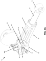
- the controlled-retraction apparatus 12 comprises the accumulator 30 and the cylinder 32 comprising the first portion 34 and the ram 36, the ram 36 coupled to the rod eye 54 to enable cooperation with the linkage 38 and idler wheel(s) 22 ( FIG. 1 ).
- the first portion 34 comprises the cylinder head 40, which includes plural fluid passageways, including the fluid passageway 46 having the port 48.
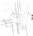
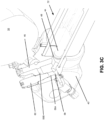
- the cylinder 32 further comprises the center rod 44, which is moveable towards and away from the port 48, regulating fluid flow through the port 48 and the accompanying fluid passageway 46. Additionally shown in FIGS.
- 3A-3C is another fluid passageway 56 (e.g., 56A, 56B), wherein the entrance to the fluid passageway 56A comprises a port 58.
- the fluid passageway 56 is fluidly coupled (after activation of the pressure relief valve as explained below) to the fluid passageway 46.
- the passage of fluid through the fluid passageway 56 is regulated by a pressure relief valve 60.
- the pressure relief valve 60 may be embodied as a cartridge-style, direct acting pressure relief valve.
- the pressure relief valve 60 may be field adjustable or preset at a fixed pressure setting (e.g., set at the factory with the intent of no adjustment in the field).
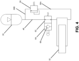
- FIG. 4 conceptually illustrates various functionality of an embodiment of a controlled-retraction apparatus 12.
- FIG. 4 illustrates functionality for the accumulator 30 and cylinder 32, including center rod-port open functionality 62 and check valve functionality 64, as further explained below.
- the center rod-port open functionality 62 corresponds to the configuration shown in FIG. 3B .
- the center rod 44 in normal operation (e.g., not an emergency braking event), the center rod 44 is not in contact with the port 48 (as represented by the center rod-port open functionality 62), and thus fluid flows (in an amount depending on the required tension) from the cylinder 32 to the inlet port 39 of the accumulator 30 via fluid passageway 46.
- the pressure relief valve 60 prevents fluid flow through the fluid passageway 56 to the accumulator 30.
- the center rod 44 when the pressure inside the accumulator 30 is greater than the force of the compression spring 52, the center rod 44 is allowed to retract inside the ram 36. In this manner, the center rod 44 is acting like a typical check valve 66 commonly used in hydraulic systems.
- the (primary) fluid passageway 46 is blocked (e.g., provided a pressure differential has not lifted the center rod 44 off of the port 48 of the cylinder head 40), the fluid flow re-routed to the fluid passageway 56.
- a second fluid flow path is enabled via the fluid passageway 56 (e.g., 56A and 56B), based on the regulation of fluid flow through the fluid passageway 56 by the normally-closed pressure relief valve 60.
- the pressure relief valve 60 activates (opens), and fluid (e.g., oil) flows from the rod guide 42 to the accumulator 30 via the fluid passageway 56, effectively bypassing the fluid passageway 46 closed off by the center rod 44.
- the prevention of fluid flow through the fluid passageway 46 corresponds to the increased resistance to retraction of the ram 36 (and hence idler wheel(s) 22) responsive to an emergency braking operation.
- This increased resistance occurs during a specific stroke range of the ram 36, which corresponds to a defined retraction distance of the center rod 44.
- the pressure at the inlet port 39 to the accumulator 30 and the cylinder 32 remains the same until the center rod 44 closes off the port 48.
- the port 48 becoming closed, fluid flow is re-routed to the port 58 corresponding to the passageway 56 in which the pressure relief valve 60 regulates flow, resulting in a rapid increase in pressure in the cylinder 32.
- the pressure relief valve 60 activates (e.g., immediately upon closing of the port 48), permitting fluid flow through the passageway 56 and to the inlet port 39 of the accumulator 30.
- the amount of resistance to the retraction is dictated by the pressure relief valve setting, enabling a controlled retraction of the ram 36 to reduce the risk of, or even prevent, slippage/jumping at the interface between the endless track belt 20 and the drive wheel 24.
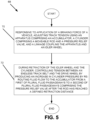
- a track tensioning method 68 for controlling/adjusting track tension for an endless track system for a vehicle comprising a drive wheel, an idler wheel, and an endless track belt, and described in FIG.
- 5 comprises: responsive to application of a braking force of the vehicle, adjusting the track tension using an apparatus comprising an accumulator, a cylinder comprising a moveable rod and a pressure relief valve, and a linkage coupling the apparatus and the idler wheel (70); and during retraction of the idler wheel and the cylinder, controlling tension between the endless track and the drive wheel by producing an increase in cylinder pressure by re-routing fluid flow to the accumulator from through a first of plural fluid passageways to a second of the plural fluid passageways comprising the pressure relief valve after the rod has reached a defined retraction distance (72).
Landscapes
- Engineering & Computer Science (AREA)
- Mechanical Engineering (AREA)
- Chemical & Material Sciences (AREA)
- Combustion & Propulsion (AREA)
- Transportation (AREA)
- Physics & Mathematics (AREA)
- Fluid Mechanics (AREA)
- General Engineering & Computer Science (AREA)
- Devices For Conveying Motion By Means Of Endless Flexible Members (AREA)
Claims (14)
- Gleiskettensystem (10) mit einem Gleiskettenrahmen (18), der ein Antriebsrad (24), ein Leitrad (22) und ein Gleiskettenband (20) aufweist; und einem Gleiskettenspannsystem, das einen Hydraulikzylinder (32) umfasst, der fluidisch an eine Druckfluidquelle gekoppelt ist; dadurch gekennzeichnet, dass die Druckfluidquelle ein Druckspeicher ist und dass das Gleiskettenspannsystem eine gesteuerte Rückzugsvorrichtung (12) umfasst, die aufweist:den Zylinder mit einem ersten Bereich (34), der einen ersten Anschluss (48), einen zweiten Anschluss (58) und ein Druckbegrenzungsventil (60) aufweist, wobei das Druckbegrenzungsventil konfiguriert ist, um Fluidfluss von dem zweiten Anschluss zu dem Druckspeicher zu regeln;einen Druckkolben (36) in verschiebbarer Beziehung zu dem ersten Bereich, wobei der Druckkolben eine innere Ausnehmung (53) und eine vordefinierte Hublänge aufweist;eine Feder (52), die in der inneren Ausnehmung angeordnet ist; undeine Stange (44), die von der Feder relativ zu dem ersten Anschluss beweglich ist, während sie Fluidfluss erlaubt;wobei der Zylinder (32) konfiguriert ist, um den Widerstand gegenüber Rückzug des Druckkolbens (36) durch Umleiten von Fluidfluss zu dem Druckspeicher (30) durch das Druckbegrenzungsventil (60) zu erhöhen, nachdem die Stange eine definierte Rückzugsstrecke erreicht hat;wobei die Vorrichtung konfiguriert ist, um die Spannung zwischen dem Gleiskettenband (20) und dem Antriebsrad (24) zu steuern, indem sie durch das Umleiten des Fluidflusses einen Anstieg beim Zylinderdruck erzeugt.
- Gleiskettensystem (10) nach Anspruch 1, wobei der erste Bereich einen Zylinderkopf (40) and eine Stangenführung (42) aufweist, wobei der Zylinderkopf den ersten Anschluss (48), den zweiten Anschluss (58) und das Druckbegrenzungsventil (60) aufweist.
- Gleiskettensystem (10) nach Anspruch 2, wobei die Stange (44) zwischen der Feder (52) und dem Zylinderkopf (40) angeordnet ist.
- Gleiskettensystem (10) nach Anspruch 2 oder 3, wobei der Druckspeicher einen Anschluss (39) aufweist und der erste Bereich mehrere Fluidkanäle aufweist, wobei die mehreren Fluidkanäle einen ersten Fluidkanal (46) aufweisen, der den ersten Anschluss (48) fluidisch an den Druckspeicheranschluss (39) koppelt, und einen zweiten Fluidkanal (56), der den zweiten Anschluss (58) an den ersten Fluidkanal (46) koppelt.
- Gleiskettensystem (10) nach Anspruch 4, wobei das Druckbegrenzungsventil (60) konfiguriert ist, um Fluss von dem ersten Anschluss (58) zu dem ersten Fluidkanal (46) über den zweiten Fluidkanal (56) zu regeln.
- Gleiskettensystem System (10) nach Anspruch 4 oder 5, wobei das Druckbegrenzungsventil (60) konfiguriert ist, um bei Aktivierung Fluidfluss von dem zweiten Anschluss (58) zu dem ersten Fluidkanal (46) zu erlauben, wenn die Stange (44) Fluidfluss von dem ersten Anschluss (48) zu dem Druckspeicher (30) verhindert.
- Gleiskettensystem (10) nach einem der Ansprüche 4 bis 6, wobei das Druckbegrenzungsventil (60) konfiguriert ist, um Fluidfluss von dem zweiten Anschluss (58) zu dem ersten Fluidkanal (46) zu verhindern, wenn die Stange (44) Fluidfluss von dem ersten Anschluss (48) zu dem Druckspeicher (30) erlaubt.
- Gleiskettensystem (10) nach Anspruch 4, wobei die gesteuerte Rückzugsvorrichtung (12) so konfiguriert ist, dass die Stange (44) den ersten Anschluss (48) verschließt, wenn die Stange die definierte Rückzugsstrecke erreicht hat, so dass das Fluid zu dem zweiten Fluidkanal (56) umgeleitet wird.
- Gleiskettensystem (10) nach einem der vorhergehenden Ansprüche, wobei der Druckkolben (36) betrieblich mit dem Leitrad (22) verbunden ist, um das Leitrad (22) auszufahren und zurückzuziehen, um die Spannung des Gleiskettenbands zu steuern, wobei der Druckkolben (36) betrieblich über ein Gestänge (38) mit dem Leitrad (22) verbunden ist.
- Verfahren zum Spannen eines Gleiskettensystems (10) nach einem der vorhergehenden Ansprüche, wobei das Verfahren aufweist: Einstellen der Gleiskettenspannung unter Verwendung der gesteuerten Rückzugsvorrichtung (12) als Reaktion auf die Anwendung einer Bremskraft und, während des Rückzugs des Leitrads (22) und Zylinders (32), Steuern der Spannung zwischen dem Gleiskettenband (20) und dem Antriebsrad (24) durch Erzeugen eines Anstiegs beim Zylinderdruck durch Umleiten von Fluidfluss zu dem Druckspeicher (30) aus einem ersten von mehreren Fluidkanälen (46) zu einem zweiten der mehreren Fluidkanäle (56), der das Druckbegrenzungsventil (60) aufweist, nachdem die Stange die definierte Rückzugsstrecke erreicht hat.
- Verfahren nach Anspruch 10, wobei das Verfahren weiterhin das Regeln von Fluss von dem zweiten Anschluss (58) zu dem ersten der mehreren Fluidkanäle (46) aufweist.
- Verfahren nach Anspruch 11, wobei die gesteuerte Rückzugsvorrichtung (12) derart konfiguriert ist, dass die Stange (44) den ersten Anschluss (48) verschließt, wenn sie die definierte Rückzugsstrecke erreicht, wobei das Verfahren das Erlauben von Fluidfluss von dem zweiten Anschluss (58) zu dem ersten der mehreren Fluidkanäle (46) aufweist, wenn durch die Stange (44) Fluidfluss durch den ersten Anschluss (48) verhindert wird.
- Verfahren nach Anspruch 12, wobei das Verfahren weiterhin das Verhindern von Fluidfluss von dem zweiten Anschluss (58) zu dem ersten der mehreren Fluidkanäle (46) aufweist, wenn der erste Anschluss (48) nicht von der Stange (44) verschlossen ist.
- Verfahren nach einem der Ansprüche 10 bis 13, wobei Einstellung der Gleiskettenspannung das Bewegen des Druckkolbens (36) über eine vordefinierte Hublänge umfasst.
Applications Claiming Priority (2)
| Application Number | Priority Date | Filing Date | Title |
|---|---|---|---|
| US201862779007P | 2018-12-13 | 2018-12-13 | |
| PCT/IB2019/059257 WO2020121080A1 (en) | 2018-12-13 | 2019-10-29 | Controlled cylinder retraction with a closed hydraulic system |
Publications (2)
| Publication Number | Publication Date |
|---|---|
| EP3894307A1 EP3894307A1 (de) | 2021-10-20 |
| EP3894307B1 true EP3894307B1 (de) | 2023-10-18 |
Family
ID=68426558
Family Applications (1)
| Application Number | Title | Priority Date | Filing Date |
|---|---|---|---|
| EP19797812.5A Active EP3894307B1 (de) | 2018-12-13 | 2019-10-29 | Gesteuerte zylinderretraktion mit einem geschlossenen hydrauliksystem |
Country Status (3)
| Country | Link |
|---|---|
| US (1) | US12084134B2 (de) |
| EP (1) | EP3894307B1 (de) |
| WO (1) | WO2020121080A1 (de) |
Families Citing this family (6)
| Publication number | Priority date | Publication date | Assignee | Title |
|---|---|---|---|---|
| US11685453B2 (en) * | 2020-05-22 | 2023-06-27 | Deere & Company | Track tension management system and method |
| US11807321B2 (en) * | 2020-05-22 | 2023-11-07 | Deere & Company | Active tension system and method |
| US20230182833A1 (en) * | 2021-12-10 | 2023-06-15 | Cnh Industrial America Llc | System and method for braking a track module of a work vehicle |
| EP4486635A4 (de) * | 2022-03-03 | 2026-03-04 | Camso Inc | Gleiskettensystem zur traktion eines fahrzeugs |
| CN115027587A (zh) * | 2022-05-11 | 2022-09-09 | 嘉兴泰特橡胶有限公司 | 用于履带行走系统的张紧机构 |
| GB2627215A (en) * | 2023-02-15 | 2024-08-21 | Outland Group Ltd | A track assembly for a vehicle |
Family Cites Families (10)
| Publication number | Priority date | Publication date | Assignee | Title |
|---|---|---|---|---|
| US3101977A (en) * | 1958-03-07 | 1963-08-27 | Letourneau Westinghouse Compan | Hydraulic track tensioning means |
| US2998998A (en) | 1958-03-07 | 1961-09-05 | Letourneau Westinghouse Compan | Load responsive track tensioning device |
| US4227748A (en) * | 1978-05-26 | 1980-10-14 | Caterpillar Tractor Co. | Track tensioning apparatus |
| US5005920A (en) * | 1990-03-26 | 1991-04-09 | Caterpillar Inc. | Track adjusting mechanism |
| US6027185A (en) | 1997-12-18 | 2000-02-22 | Caterpillar Inc. | Recoil and slack adjustment mechanism for an endless track chain of an undercarriage assembly |
| US6336690B2 (en) * | 1999-06-17 | 2002-01-08 | Caterpillar Inc. | Track tensioning apparatus |
| US6305762B1 (en) * | 1999-12-16 | 2001-10-23 | Caterpillar Inc. | Valve assembly for controlling actuation of an actuator of a track tensioning system |
| DE10257405A1 (de) * | 2001-12-21 | 2003-07-10 | Caterpillar Inc | System zur Einstellung der Ketten- bzw. Bandspannung |
| JP2004314938A (ja) * | 2003-03-31 | 2004-11-11 | Komatsu Ltd | 履帯張力調整装置 |
| US10336382B2 (en) * | 2016-02-03 | 2019-07-02 | Cnh Industrial America Llc | Track vehicle with fluidly damped idler recoil system |
-
2019
- 2019-10-29 WO PCT/IB2019/059257 patent/WO2020121080A1/en not_active Ceased
- 2019-10-29 EP EP19797812.5A patent/EP3894307B1/de active Active
- 2019-10-29 US US17/312,520 patent/US12084134B2/en active Active
Also Published As
| Publication number | Publication date |
|---|---|
| US20220049726A1 (en) | 2022-02-17 |
| WO2020121080A1 (en) | 2020-06-18 |
| EP3894307A1 (de) | 2021-10-20 |
| US12084134B2 (en) | 2024-09-10 |
Similar Documents
| Publication | Publication Date | Title |
|---|---|---|
| US12084134B2 (en) | Controlled cylinder retraction with a closed hydraulic system | |
| US11286013B2 (en) | Dynamic tensioner locking device for a track system and method thereof | |
| US6024183A (en) | Track belt tension management system | |
| US3647270A (en) | Hydraulic chain-tensioning device, especially for tracklaying vehicles | |
| US4681376A (en) | Apparatus for tensioning a track chain of a tracklaying vehicle | |
| US6027185A (en) | Recoil and slack adjustment mechanism for an endless track chain of an undercarriage assembly | |
| US10640162B2 (en) | Tensioning system for an endless track system | |
| GB2093150A (en) | Improvements in or relating to tensioning devices for endless chains | |
| US4406501A (en) | Recoil system with guided slide assembly for track-type vehicles | |
| CN210235140U (zh) | 一种履带张紧机构及履带式车辆 | |
| EP1361143A2 (de) | Spannregelungssystem für Gleisketten | |
| US9523414B2 (en) | Variable flow hydraulic chain tensioner | |
| EP0454668B1 (de) | Durchflussregelungsvorrichtung für kettenspanner | |
| US4149757A (en) | Automatic track chain tensioner | |
| EP3202648B1 (de) | Kettenfahrzeug mit fluidgedämpfter spannrollen-rückstellanordnung | |
| US11046375B2 (en) | Track roller unit for an agricultural working machine | |
| JP6359571B2 (ja) | チェーンドライブテンショナばね力制御機構 | |
| CN104428199A (zh) | 车高调整装置 | |
| EP0533663B1 (de) | Laufkettenspannungsvorrichtung | |
| US4854650A (en) | Track recoil and tensioning mechanism | |
| GB2393696A (en) | Tensioning system for a tracked vehicle | |
| CA2982193C (en) | Dynamic tensioner locking device for a track system and method thereof | |
| US4323283A (en) | Track adjusting and recoil apparatus for use with crawler vehicles | |
| US20170081810A1 (en) | Road finishing machine with pushing device | |
| GB2449513A (en) | Continuous track tensioning system |
Legal Events
| Date | Code | Title | Description |
|---|---|---|---|
| STAA | Information on the status of an ep patent application or granted ep patent |
Free format text: STATUS: UNKNOWN |
|
| STAA | Information on the status of an ep patent application or granted ep patent |
Free format text: STATUS: THE INTERNATIONAL PUBLICATION HAS BEEN MADE |
|
| PUAI | Public reference made under article 153(3) epc to a published international application that has entered the european phase |
Free format text: ORIGINAL CODE: 0009012 |
|
| STAA | Information on the status of an ep patent application or granted ep patent |
Free format text: STATUS: REQUEST FOR EXAMINATION WAS MADE |
|
| 17P | Request for examination filed |
Effective date: 20210713 |
|
| AK | Designated contracting states |
Kind code of ref document: A1 Designated state(s): AL AT BE BG CH CY CZ DE DK EE ES FI FR GB GR HR HU IE IS IT LI LT LU LV MC MK MT NL NO PL PT RO RS SE SI SK SM TR |
|
| DAV | Request for validation of the european patent (deleted) | ||
| DAX | Request for extension of the european patent (deleted) | ||
| STAA | Information on the status of an ep patent application or granted ep patent |
Free format text: STATUS: EXAMINATION IS IN PROGRESS |
|
| 17Q | First examination report despatched |
Effective date: 20221108 |
|
| GRAP | Despatch of communication of intention to grant a patent |
Free format text: ORIGINAL CODE: EPIDOSNIGR1 |
|
| STAA | Information on the status of an ep patent application or granted ep patent |
Free format text: STATUS: GRANT OF PATENT IS INTENDED |
|
| GRAJ | Information related to disapproval of communication of intention to grant by the applicant or resumption of examination proceedings by the epo deleted |
Free format text: ORIGINAL CODE: EPIDOSDIGR1 |
|
| STAA | Information on the status of an ep patent application or granted ep patent |
Free format text: STATUS: EXAMINATION IS IN PROGRESS |
|
| P01 | Opt-out of the competence of the unified patent court (upc) registered |
Effective date: 20230518 |
|
| INTG | Intention to grant announced |
Effective date: 20230605 |
|
| GRAP | Despatch of communication of intention to grant a patent |
Free format text: ORIGINAL CODE: EPIDOSNIGR1 |
|
| STAA | Information on the status of an ep patent application or granted ep patent |
Free format text: STATUS: GRANT OF PATENT IS INTENDED |
|
| INTC | Intention to grant announced (deleted) | ||
| INTG | Intention to grant announced |
Effective date: 20230718 |
|
| GRAS | Grant fee paid |
Free format text: ORIGINAL CODE: EPIDOSNIGR3 |
|
| GRAA | (expected) grant |
Free format text: ORIGINAL CODE: 0009210 |
|
| STAA | Information on the status of an ep patent application or granted ep patent |
Free format text: STATUS: THE PATENT HAS BEEN GRANTED |
|
| AK | Designated contracting states |
Kind code of ref document: B1 Designated state(s): AL AT BE BG CH CY CZ DE DK EE ES FI FR GB GR HR HU IE IS IT LI LT LU LV MC MK MT NL NO PL PT RO RS SE SI SK SM TR |
|
| REG | Reference to a national code |
Ref country code: GB Ref legal event code: FG4D |
|
| REG | Reference to a national code |
Ref country code: CH Ref legal event code: EP |
|
| REG | Reference to a national code |
Ref country code: IE Ref legal event code: FG4D |
|
| REG | Reference to a national code |
Ref country code: DE Ref legal event code: R096 Ref document number: 602019039692 Country of ref document: DE |
|
| REG | Reference to a national code |
Ref country code: LT Ref legal event code: MG9D |
|
| REG | Reference to a national code |
Ref country code: NL Ref legal event code: MP Effective date: 20231018 |
|
| REG | Reference to a national code |
Ref country code: AT Ref legal event code: MK05 Ref document number: 1622216 Country of ref document: AT Kind code of ref document: T Effective date: 20231018 |
|
| PG25 | Lapsed in a contracting state [announced via postgrant information from national office to epo] |
Ref country code: NL Free format text: LAPSE BECAUSE OF FAILURE TO SUBMIT A TRANSLATION OF THE DESCRIPTION OR TO PAY THE FEE WITHIN THE PRESCRIBED TIME-LIMIT Effective date: 20231018 |
|
| PG25 | Lapsed in a contracting state [announced via postgrant information from national office to epo] |
Ref country code: GR Free format text: LAPSE BECAUSE OF FAILURE TO SUBMIT A TRANSLATION OF THE DESCRIPTION OR TO PAY THE FEE WITHIN THE PRESCRIBED TIME-LIMIT Effective date: 20240119 |
|
| PG25 | Lapsed in a contracting state [announced via postgrant information from national office to epo] |
Ref country code: IS Free format text: LAPSE BECAUSE OF FAILURE TO SUBMIT A TRANSLATION OF THE DESCRIPTION OR TO PAY THE FEE WITHIN THE PRESCRIBED TIME-LIMIT Effective date: 20240218 |
|
| PG25 | Lapsed in a contracting state [announced via postgrant information from national office to epo] |
Ref country code: LT Free format text: LAPSE BECAUSE OF FAILURE TO SUBMIT A TRANSLATION OF THE DESCRIPTION OR TO PAY THE FEE WITHIN THE PRESCRIBED TIME-LIMIT Effective date: 20231018 |
|
| PG25 | Lapsed in a contracting state [announced via postgrant information from national office to epo] |
Ref country code: AT Free format text: LAPSE BECAUSE OF FAILURE TO SUBMIT A TRANSLATION OF THE DESCRIPTION OR TO PAY THE FEE WITHIN THE PRESCRIBED TIME-LIMIT Effective date: 20231018 |
|
| PG25 | Lapsed in a contracting state [announced via postgrant information from national office to epo] |
Ref country code: ES Free format text: LAPSE BECAUSE OF FAILURE TO SUBMIT A TRANSLATION OF THE DESCRIPTION OR TO PAY THE FEE WITHIN THE PRESCRIBED TIME-LIMIT Effective date: 20231018 |
|
| PG25 | Lapsed in a contracting state [announced via postgrant information from national office to epo] |
Ref country code: LT Free format text: LAPSE BECAUSE OF FAILURE TO SUBMIT A TRANSLATION OF THE DESCRIPTION OR TO PAY THE FEE WITHIN THE PRESCRIBED TIME-LIMIT Effective date: 20231018 Ref country code: IS Free format text: LAPSE BECAUSE OF FAILURE TO SUBMIT A TRANSLATION OF THE DESCRIPTION OR TO PAY THE FEE WITHIN THE PRESCRIBED TIME-LIMIT Effective date: 20240218 Ref country code: GR Free format text: LAPSE BECAUSE OF FAILURE TO SUBMIT A TRANSLATION OF THE DESCRIPTION OR TO PAY THE FEE WITHIN THE PRESCRIBED TIME-LIMIT Effective date: 20240119 Ref country code: ES Free format text: LAPSE BECAUSE OF FAILURE TO SUBMIT A TRANSLATION OF THE DESCRIPTION OR TO PAY THE FEE WITHIN THE PRESCRIBED TIME-LIMIT Effective date: 20231018 Ref country code: BG Free format text: LAPSE BECAUSE OF FAILURE TO SUBMIT A TRANSLATION OF THE DESCRIPTION OR TO PAY THE FEE WITHIN THE PRESCRIBED TIME-LIMIT Effective date: 20240118 Ref country code: AT Free format text: LAPSE BECAUSE OF FAILURE TO SUBMIT A TRANSLATION OF THE DESCRIPTION OR TO PAY THE FEE WITHIN THE PRESCRIBED TIME-LIMIT Effective date: 20231018 Ref country code: PT Free format text: LAPSE BECAUSE OF FAILURE TO SUBMIT A TRANSLATION OF THE DESCRIPTION OR TO PAY THE FEE WITHIN THE PRESCRIBED TIME-LIMIT Effective date: 20240219 |
|
| PG25 | Lapsed in a contracting state [announced via postgrant information from national office to epo] |
Ref country code: SE Free format text: LAPSE BECAUSE OF FAILURE TO SUBMIT A TRANSLATION OF THE DESCRIPTION OR TO PAY THE FEE WITHIN THE PRESCRIBED TIME-LIMIT Effective date: 20231018 Ref country code: RS Free format text: LAPSE BECAUSE OF FAILURE TO SUBMIT A TRANSLATION OF THE DESCRIPTION OR TO PAY THE FEE WITHIN THE PRESCRIBED TIME-LIMIT Effective date: 20231018 Ref country code: PL Free format text: LAPSE BECAUSE OF FAILURE TO SUBMIT A TRANSLATION OF THE DESCRIPTION OR TO PAY THE FEE WITHIN THE PRESCRIBED TIME-LIMIT Effective date: 20231018 Ref country code: NO Free format text: LAPSE BECAUSE OF FAILURE TO SUBMIT A TRANSLATION OF THE DESCRIPTION OR TO PAY THE FEE WITHIN THE PRESCRIBED TIME-LIMIT Effective date: 20240118 Ref country code: LV Free format text: LAPSE BECAUSE OF FAILURE TO SUBMIT A TRANSLATION OF THE DESCRIPTION OR TO PAY THE FEE WITHIN THE PRESCRIBED TIME-LIMIT Effective date: 20231018 Ref country code: HR Free format text: LAPSE BECAUSE OF FAILURE TO SUBMIT A TRANSLATION OF THE DESCRIPTION OR TO PAY THE FEE WITHIN THE PRESCRIBED TIME-LIMIT Effective date: 20231018 |
|
| REG | Reference to a national code |
Ref country code: CH Ref legal event code: PL |
|
| REG | Reference to a national code |
Ref country code: BE Ref legal event code: MM Effective date: 20231031 |
|
| PG25 | Lapsed in a contracting state [announced via postgrant information from national office to epo] |
Ref country code: LU Free format text: LAPSE BECAUSE OF NON-PAYMENT OF DUE FEES Effective date: 20231029 |
|
| PG25 | Lapsed in a contracting state [announced via postgrant information from national office to epo] |
Ref country code: LU Free format text: LAPSE BECAUSE OF NON-PAYMENT OF DUE FEES Effective date: 20231029 |
|
| PG25 | Lapsed in a contracting state [announced via postgrant information from national office to epo] |
Ref country code: DK Free format text: LAPSE BECAUSE OF FAILURE TO SUBMIT A TRANSLATION OF THE DESCRIPTION OR TO PAY THE FEE WITHIN THE PRESCRIBED TIME-LIMIT Effective date: 20231018 |
|
| PG25 | Lapsed in a contracting state [announced via postgrant information from national office to epo] |
Ref country code: CH Free format text: LAPSE BECAUSE OF NON-PAYMENT OF DUE FEES Effective date: 20231031 |
|
| REG | Reference to a national code |
Ref country code: DE Ref legal event code: R097 Ref document number: 602019039692 Country of ref document: DE |
|
| PG25 | Lapsed in a contracting state [announced via postgrant information from national office to epo] |
Ref country code: CZ Free format text: LAPSE BECAUSE OF FAILURE TO SUBMIT A TRANSLATION OF THE DESCRIPTION OR TO PAY THE FEE WITHIN THE PRESCRIBED TIME-LIMIT Effective date: 20231018 |
|
| PG25 | Lapsed in a contracting state [announced via postgrant information from national office to epo] |
Ref country code: SK Free format text: LAPSE BECAUSE OF FAILURE TO SUBMIT A TRANSLATION OF THE DESCRIPTION OR TO PAY THE FEE WITHIN THE PRESCRIBED TIME-LIMIT Effective date: 20231018 |
|
| PG25 | Lapsed in a contracting state [announced via postgrant information from national office to epo] |
Ref country code: SM Free format text: LAPSE BECAUSE OF FAILURE TO SUBMIT A TRANSLATION OF THE DESCRIPTION OR TO PAY THE FEE WITHIN THE PRESCRIBED TIME-LIMIT Effective date: 20231018 Ref country code: SK Free format text: LAPSE BECAUSE OF FAILURE TO SUBMIT A TRANSLATION OF THE DESCRIPTION OR TO PAY THE FEE WITHIN THE PRESCRIBED TIME-LIMIT Effective date: 20231018 Ref country code: RO Free format text: LAPSE BECAUSE OF FAILURE TO SUBMIT A TRANSLATION OF THE DESCRIPTION OR TO PAY THE FEE WITHIN THE PRESCRIBED TIME-LIMIT Effective date: 20231018 Ref country code: IT Free format text: LAPSE BECAUSE OF FAILURE TO SUBMIT A TRANSLATION OF THE DESCRIPTION OR TO PAY THE FEE WITHIN THE PRESCRIBED TIME-LIMIT Effective date: 20231018 Ref country code: EE Free format text: LAPSE BECAUSE OF FAILURE TO SUBMIT A TRANSLATION OF THE DESCRIPTION OR TO PAY THE FEE WITHIN THE PRESCRIBED TIME-LIMIT Effective date: 20231018 Ref country code: DK Free format text: LAPSE BECAUSE OF FAILURE TO SUBMIT A TRANSLATION OF THE DESCRIPTION OR TO PAY THE FEE WITHIN THE PRESCRIBED TIME-LIMIT Effective date: 20231018 Ref country code: CZ Free format text: LAPSE BECAUSE OF FAILURE TO SUBMIT A TRANSLATION OF THE DESCRIPTION OR TO PAY THE FEE WITHIN THE PRESCRIBED TIME-LIMIT Effective date: 20231018 Ref country code: CH Free format text: LAPSE BECAUSE OF NON-PAYMENT OF DUE FEES Effective date: 20231031 |
|
| PLBE | No opposition filed within time limit |
Free format text: ORIGINAL CODE: 0009261 |
|
| STAA | Information on the status of an ep patent application or granted ep patent |
Free format text: STATUS: NO OPPOSITION FILED WITHIN TIME LIMIT |
|
| PG25 | Lapsed in a contracting state [announced via postgrant information from national office to epo] |
Ref country code: MC Free format text: LAPSE BECAUSE OF FAILURE TO SUBMIT A TRANSLATION OF THE DESCRIPTION OR TO PAY THE FEE WITHIN THE PRESCRIBED TIME-LIMIT Effective date: 20231018 |
|
| PG25 | Lapsed in a contracting state [announced via postgrant information from national office to epo] |
Ref country code: MC Free format text: LAPSE BECAUSE OF FAILURE TO SUBMIT A TRANSLATION OF THE DESCRIPTION OR TO PAY THE FEE WITHIN THE PRESCRIBED TIME-LIMIT Effective date: 20231018 Ref country code: BE Free format text: LAPSE BECAUSE OF NON-PAYMENT OF DUE FEES Effective date: 20231031 |
|
| 26N | No opposition filed |
Effective date: 20240719 |
|
| GBPC | Gb: european patent ceased through non-payment of renewal fee |
Effective date: 20240118 |
|
| PG25 | Lapsed in a contracting state [announced via postgrant information from national office to epo] |
Ref country code: IE Free format text: LAPSE BECAUSE OF NON-PAYMENT OF DUE FEES Effective date: 20231029 |
|
| PG25 | Lapsed in a contracting state [announced via postgrant information from national office to epo] |
Ref country code: GB Free format text: LAPSE BECAUSE OF NON-PAYMENT OF DUE FEES Effective date: 20240118 |
|
| PG25 | Lapsed in a contracting state [announced via postgrant information from national office to epo] |
Ref country code: SI Free format text: LAPSE BECAUSE OF FAILURE TO SUBMIT A TRANSLATION OF THE DESCRIPTION OR TO PAY THE FEE WITHIN THE PRESCRIBED TIME-LIMIT Effective date: 20231018 |
|
| PG25 | Lapsed in a contracting state [announced via postgrant information from national office to epo] |
Ref country code: SI Free format text: LAPSE BECAUSE OF FAILURE TO SUBMIT A TRANSLATION OF THE DESCRIPTION OR TO PAY THE FEE WITHIN THE PRESCRIBED TIME-LIMIT Effective date: 20231018 Ref country code: IE Free format text: LAPSE BECAUSE OF NON-PAYMENT OF DUE FEES Effective date: 20231029 Ref country code: GB Free format text: LAPSE BECAUSE OF NON-PAYMENT OF DUE FEES Effective date: 20240118 |
|
| PG25 | Lapsed in a contracting state [announced via postgrant information from national office to epo] |
Ref country code: FI Free format text: LAPSE BECAUSE OF FAILURE TO SUBMIT A TRANSLATION OF THE DESCRIPTION OR TO PAY THE FEE WITHIN THE PRESCRIBED TIME-LIMIT Effective date: 20231019 |
|
| PG25 | Lapsed in a contracting state [announced via postgrant information from national office to epo] |
Ref country code: CY Free format text: LAPSE BECAUSE OF FAILURE TO SUBMIT A TRANSLATION OF THE DESCRIPTION OR TO PAY THE FEE WITHIN THE PRESCRIBED TIME-LIMIT; INVALID AB INITIO Effective date: 20191029 |
|
| PG25 | Lapsed in a contracting state [announced via postgrant information from national office to epo] |
Ref country code: HU Free format text: LAPSE BECAUSE OF FAILURE TO SUBMIT A TRANSLATION OF THE DESCRIPTION OR TO PAY THE FEE WITHIN THE PRESCRIBED TIME-LIMIT; INVALID AB INITIO Effective date: 20191029 |
|
| PG25 | Lapsed in a contracting state [announced via postgrant information from national office to epo] |
Ref country code: TR Free format text: LAPSE BECAUSE OF FAILURE TO SUBMIT A TRANSLATION OF THE DESCRIPTION OR TO PAY THE FEE WITHIN THE PRESCRIBED TIME-LIMIT Effective date: 20231018 |
|
| PGFP | Annual fee paid to national office [announced via postgrant information from national office to epo] |
Ref country code: DE Payment date: 20251021 Year of fee payment: 7 |
|
| PGFP | Annual fee paid to national office [announced via postgrant information from national office to epo] |
Ref country code: FR Payment date: 20251030 Year of fee payment: 7 |