EP3894301B1 - Lenksäule für ein kraftfahrzeug und ein verfahren zum montieren - Google Patents
Lenksäule für ein kraftfahrzeug und ein verfahren zum montieren Download PDFInfo
- Publication number
- EP3894301B1 EP3894301B1 EP19828986.0A EP19828986A EP3894301B1 EP 3894301 B1 EP3894301 B1 EP 3894301B1 EP 19828986 A EP19828986 A EP 19828986A EP 3894301 B1 EP3894301 B1 EP 3894301B1
- Authority
- EP
- European Patent Office
- Prior art keywords
- spring element
- steering column
- holding unit
- locking
- spring
- Prior art date
- Legal status (The legal status is an assumption and is not a legal conclusion. Google has not performed a legal analysis and makes no representation as to the accuracy of the status listed.)
- Active
Links
Images
Classifications
-
- B—PERFORMING OPERATIONS; TRANSPORTING
- B62—LAND VEHICLES FOR TRAVELLING OTHERWISE THAN ON RAILS
- B62D—MOTOR VEHICLES; TRAILERS
- B62D1/00—Steering controls, i.e. means for initiating a change of direction of the vehicle
- B62D1/02—Steering controls, i.e. means for initiating a change of direction of the vehicle vehicle-mounted
- B62D1/16—Steering columns
- B62D1/18—Steering columns yieldable or adjustable, e.g. tiltable
- B62D1/184—Mechanisms for locking columns at selected positions
-
- B—PERFORMING OPERATIONS; TRANSPORTING
- B62—LAND VEHICLES FOR TRAVELLING OTHERWISE THAN ON RAILS
- B62D—MOTOR VEHICLES; TRAILERS
- B62D1/00—Steering controls, i.e. means for initiating a change of direction of the vehicle
- B62D1/02—Steering controls, i.e. means for initiating a change of direction of the vehicle vehicle-mounted
- B62D1/16—Steering columns
- B62D1/18—Steering columns yieldable or adjustable, e.g. tiltable
- B62D1/19—Steering columns yieldable or adjustable, e.g. tiltable incorporating energy-absorbing arrangements, e.g. by being yieldable or collapsible
- B62D1/195—Yieldable supports for the steering column
Definitions
- the invention relates to a steering column for a motor vehicle comprising an actuating unit in which a steering shaft is rotatably mounted, a holding unit which can be connected to the body of the motor vehicle and carries the actuating unit, wherein the actuating unit is adjustable relative to the holding unit, at least one locking element which is movably coupled to the holding unit for axially locking the actuating unit, at least one spring element which exerts a prestressing force on the locking element, at least one securing element for fixing the spring element.
- the invention further relates to a method for assembly.
- a steering column according to the preamble of claim 1 is for example made of EN 10 2016 214 709 A1 known.
- steering columns for motor vehicles are known in which a steering wheel position can be adjusted to the seating position of the driver of a motor vehicle.
- the steering column has a steering spindle to which a steering wheel is attached.
- the steering column is essentially adjustable in such a way that the steering wheel can be positioned in the vehicle interior by adjusting the length in the longitudinal direction of the steering column.
- the steering column has a clamping device to fix the steering spindle with the steering wheel in the desired position.
- a steering column with a clamping device is known, for example, from the EN 10 2016 214 709 A1
- the steering column comprises a casing unit and an inner casing tube in which a steering spindle is rotatably mounted.
- the inner casing tube is telescopically adjustable in the direction of the longitudinal axis of the steering spindle and can be adjusted to different positions by means of a detachable clamping device. Steering wheel positions can be locked.
- the casing unit is mounted on the body of the vehicle.
- the known clamping device has a locking element that can be positively connected to an engagement part and is arranged to be displaceable in the casing unit.
- the engagement part is coupled to the inner casing tube.
- the clamping device also has a cam and a clamping bolt that is rotatably mounted in the casing unit.
- the cam is connected to the clamping bolt in such a way that the clamping bolt interacts with the locking element through a rotational movement.
- the locking element is raised or lowered by the rotational movement of the cam. In the release position, the locking element and the engagement element are decoupled from one another.
- the locking element has a cam track to raise or lower the locking element.
- the cam interacts with the cam track of the locking element to fix or release the steering spindle.
- the tensioning device has a spring element that engages the locking element.
- the spring element is arranged in a holder such that the spring element is firmly connected to the holder with a free end.
- the invention is based on the object of providing a steering column with an improved clamping device which is simple and cost-effective in construction and easy to assemble.
- a steering column for a motor vehicle which comprises an actuating unit in which a steering shaft is rotatably mounted.
- the steering column comprises a holding unit that can be connected to the body of the motor vehicle and carries the actuating unit, wherein the actuating unit is adjustable relative to the holding unit.
- the steering column has at least one locking element that is movably coupled to the holding unit for axially locking the actuating unit, and at least one spring element that exerts a preload force on the locking element.
- the steering column also comprises at least one securing element for fixing the spring element, wherein the locking element, the securing element and a counter bearing form a three-point arrangement in which the spring element is positioned and fixed.
- the spring element is supported on the one hand on the locking element and on the other hand on the counter bearing.
- a securing element that preloads the spring element is arranged between the locking element and the counter bearing.
- the invention has the advantage that it is a self-locking system in which the securing element fulfils a dual function. Both the pre-tensioning and the securing or fixing of the spring element are carried out by the securing element. This means that no additional screwing or riveting process is required to pre-tension or fix the spring element.
- the counter bearing forms a first point, in particular the first bearing point or first holding point of the three-point arrangement.
- the locking element forms a second point, in particular the second bearing point or second holding point of the three-point arrangement.
- the securing element forms a third point, in particular the third bearing point or third holding point of the three-point arrangement.
- the securing element or generally the third point of the three-point arrangement is arranged between the locking element and the counter bearing, i.e. between the second and first point of the three-point arrangement.
- the locking element and the counter bearing, i.e. the second and first point of the three-point arrangement form a line.
- the securing element or generally the third point of the three-point arrangement is arranged on a vertical that intersects this line, namely between the locking element and the counter bearing, i.e. between the second and first point of the three-point arrangement.
- at least the line of contact between the securing element and the spring element lies outside the line between the locking element and the counter bearing, i.e. between the second and first point of the three-point arrangement.
- the securing element or generally the third point of the three-point arrangement can also be arranged directly on the line, for example if the spring element is curved in the rest position.
- the counter bearing in particular the counter bearing and the locking element on the one hand and the securing element on the other hand are preferably arranged on opposite sides of the spring element in the assembled state.
- the spring element is arranged, in particular clamped, between the securing element on the one hand and the counter bearing and the locking element on the other.
- the position of the three points described above means that the spring element can be clamped into the three-point arrangement or is clamped in such a way that a pre-tensioning force acts on the locking element, forcing the locking element into the locking position.
- the three-point arrangement and the spring element work together in such a way that the spring element is deflected from the rest position when clamped and is fixed in the deflected state.
- the spring element is elastically deformed when deflected.
- the spring element can, for example, be straight when at rest.
- the three-point arrangement then results in a bending line of the spring element, along which the spring element deforms when clamped. In the deformed state, the spring element can be continuously curved.
- the position of the three points, locking element, counter bearing and securing element, relative to one another determines the bending line of the spring element and thus the spring force that acts on the locking element.
- the spring element it is also possible for the spring element to be curved when at rest and at least partially stretched when clamped in the three-point arrangement.
- the three-point arrangement and the spring element work together in such a way that the locking element is subjected to a pre-tensioning force.
- the spring element can be designed as a leaf spring, i.e. as a flat, leaf-shaped spring.
- the spring element can, for example, be formed by a spring tongue that tapers at one end.
- the spring tongue has in particular a trapezoidal shape, with the base resting on the counter bearing and the parallel opposite side or the parallel opposite end of the spring tongue resting on the locking element.
- the base and the parallel opposite side form the base sides of the trapezoidal spring tongue.
- the base is longer than the parallel opposite side or the end.
- the spring element can be deflected using an assembly tool and positioned in the three-point arrangement, e.g. by pushing it in. It is also possible to position and deflect the spring element on the locking element and the counter bearing so that the securing element can be inserted into the holding unit in order to secure and fix the spring element in the pre-tensioned state.
- the adjustment of the required preload force on the locking element is achieved by the spacing between the locking element and the spring element as well as between the securing element and the spring element.
- the spring element pre-tensions the locking element against the engagement element when it is mounted.
- the spring element thus pre-tensions the locking element in the direction of the engagement element. This enables the locking element to engage securely in the engagement element.
- the locking element can be moved into the fixing position or locking position by the spring element.
- the spring element pre-tensions the locking element in such a way that the clamping lever is securely closed and the locking element is thus securely moved into the fixing position.
- the steering column has at least one tension shaft which is connected in a rotationally fixed manner to a cam which actuates the locking element for releasing or locking the actuating unit.
- the tension shaft can be coupled to a lever and a clamping device, wherein the clamping device is positioned between a release position and a fixing position.
- the Coupling has the advantage that the clamping device can be designed, for example, as a compact cam or tilt pin clamping device.
- the securing element can be designed as a pin-like component that is firmly connected to the holding unit. This type of connection has the advantage that it is simpler and more cost-effective than fixing using a screw.
- cylindrical pins with a round, circular cylindrical or any cross-section can be used.
- the securing element can also be designed as a split pin, as a pin with two fitting sections or as a grooved fitting pin in accordance with ISO 8745.
- the fixed connection of the securing element in the holding unit can be realized in that the spring element applies a force to the securing element in the radial direction, i.e. in a direction orthogonal to the longitudinal axis of the securing element, such that the latter is held in a force-locking manner on the holding unit.
- the securing element is held in the holding unit by the pre-tensioning force of the spring element against falling out in the direction of the longitudinal axis.
- the securing element can be pressed into an opening in the holding unit.
- an interference fit can be provided between the securing element and the opening.
- the securing element is inserted into the holding unit in a direction that is angular, in particular orthogonal to the longitudinal axis of the spring element.
- the deflection direction is the direction that is orthogonal to the longitudinal position of the spring element and directed into the holding unit.
- the securing element is pressed into one of the two openings in the holding unit. This enables cost-effective and quick installation.
- the spring element has a projection that engages in a lateral recess of the holding unit. This prevents the spring element from being inserted the wrong way round during assembly.
- the counter bearing has a positioning element which engages in a corresponding structure of the spring element.
- the securing element has knurling, in particular longitudinal knurling with a large number of teeth. This means that lower pressing forces are required during assembly. Furthermore, the knurling offers increased security against twisting.
- a secondary aspect of the invention relates to a method for mounting a spring element in a steering column according to the preamble of claim 1, in which the spring element is positioned within a three-point arrangement and is pre-tensioned with an assembly force, wherein the securing element is then firmly connected to the holding unit in order to fix the spring element in the pre-tensioned state.
- the firm connection of the securing element in the holding unit can be realized in that the spring element applies a force to the securing element in the radial direction, i.e. in a direction orthogonal to the longitudinal axis of the securing element, in such a way that the latter is held force-fittingly on the holding unit.
- the securing element can be pressed into an opening in the holding unit.
- an interference fit can be provided between the securing element and the opening.
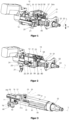
- FIG. 1 shows a perspective view of a steering column 10 to explain the installation situation of the relevant components.
- the general installation situation is also explained in connection with the embodiment according to the invention according to Fig. 5-13 disclosed.
- the steering column 10 comprises an actuating unit 11, a holding unit 12 and a tensioning device 20.
- the steering column 10 can be fastened to a body of a motor vehicle (not shown) by the holding unit 12.
- the holding unit 12 has a holding element 54 in the form of a bracket, by means of which the steering column 10 can be connected to the body of the motor vehicle.
- the holding element 54 comprises fastening means 54a for connection to the body.
- the holding element 54 also has side cheeks 55, 56 which are spaced apart from one another. The side cheeks 55, 56 are arranged in such a way that the holding unit 12 is received between the side cheeks 55, 56.
- the actuating unit 11 is arranged in the holding unit 12.
- the actuating unit 11 comprises a steering spindle 52 and a casing tube 51.
- the steering spindle 52 and the casing tube 51 have a common longitudinal axis L.
- the steering spindle 52 is mounted in the casing tube 51 so as to be rotatable about the longitudinal axis L.
- the steering spindle 52 has a rear end 53, to which a steering wheel (not shown) can be attached to the steering spindle 52.
- the casing tube 51 is held in a receptacle of the holding unit 12.
- the clamping device 20 has a clamping lever 21, a clamping shaft 22 and a cam 23.
- the clamping lever 21 is connected to the clamping shaft 22 in a rotationally fixed manner.
- the clamping shaft 22 is guided transversely to the longitudinal axis L through elongated holes 57 in the opposing side cheeks 55, 56 and through a through opening in the holding unit 12.
- the clamping device 20 here comprises a generally known clamping mechanism with a tilting pin arrangement 24 and a support disk 25.
- the tilting pin arrangement 24 is connected to the tensioning shaft 22 in a rotationally fixed manner. Furthermore, the support disk 25 of the tilting pin arrangement 24 is connected to the side cheek 55 in a rotationally fixed manner opposite.
- the tensioning lever 21 and the tensioning shaft 22 connected thereto By rotating the tensioning lever 21 and the tensioning shaft 22 connected thereto, the support disk 25 is axially displaced relative to the tensioning lever 21 and the tensioning shaft 22.
- the support disk 25 is thereby pressed from the outside against the side cheek 55.
- the tensioning shaft 22 is mounted on the opposite side cheek 56 in an axially displaceable manner, for example by a hexagon nut acting as a counterbearing, which has an internal thread and is screwed onto an external thread of the tension shaft 22.
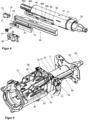
- Figure 3 is a perspective view of an actuator unit 11 as described above. Furthermore, Figure 3 a locking device 30, a coupling device 60 and an energy absorption device 80.
- the locking device 30 has a locking element 31 and an engagement element 33.
- the locking element 31 is mounted in the holding unit 12 so that it cannot move in the direction of the longitudinal axis L. In the height direction H, the locking element 31 is mounted so that it can be adjusted in height to set the locking position or the release position of the clamping lever 21. In other words, the locking element 31 is arranged in the holding unit 12 such that the locking element 31 can be moved in the holding unit 12 in the height direction H.
- the engagement element 33 is connected to the casing tube 51 via an energy absorption device 80.
- the locking element 31 and the engagement element 33 have positive locking means 31a, 33a.
- the positive locking means 31a, 33a can be brought into positive engagement by a lifting movement of the locking element 31.
- the engagement element 33 has a connecting part 71.
- the connecting part 71 forms a separate part which is connected to the engagement element 33 by a coupling device 60.
- a bolt 61 of the coupling device 60 engages in a bore 72 of the connecting part 71.
- the coupling device 60 is firmly connected to the engagement element 33.
- the actuation of the coupling device 60 enables the mechanical connection between the engagement element 33 and the connecting part 71 to be released by moving a bolt 61 of the coupling device 60 from an extended position to a retracted position by means of a pyrotechnic propellant charge.
- the connecting part 71 is separated from the engagement element 33, wherein the connecting part 71 and the engagement element 33 can be moved independently of one another in the longitudinal direction L.
- energy absorption elements 64, 66 are arranged in the inner profile 63 at a distance from one another.
- the energy absorption elements 64, 66 are each designed as a U-shaped bending wire, in particular bending strip.
- the respective energy absorption element 64, 66 is connected to a second leg by a first leg bending by 180°.
- a driver hook 64b, 66b is formed by a bend against the first leg.
- the energy absorption elements 64, 66 can be designed as stamped parts.
- the connecting part 71 has a pin 74 which is in operative engagement with the driver hook 64b and engages in the eyelet-shaped recess 64a formed by the bend and the driver hook 64b.
- the engagement element 33 has a pin 77 which is in operative engagement with the driver hook 66b and engages in the eyelet-shaped recess 66a formed by the bend and the driver hook 66b.
- both energy absorption elements 64, 66 are deformed simultaneously to provide a high crash level.
- a second crash case in which the engagement element 33 is decoupled from the connecting element 71, only the energy absorption element 66 is deformed and the energy absorption element 64 remains undeformed to provide a low crash level.
- FIG. 5 shows a perspective view of the steering column 10 in the assembled state according to an embodiment of the invention.
- the Figures 1-4 The components explained are in the steering column 10 according to Figure 5 also installed. Please refer to the above explanations.
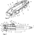
- FIG 6 is a detailed view of the clamping device 20 according to Figure 5 shown.
- the holding unit 12 has a spring element 35 which presses the locking element 31 against the engagement element 33.
- the spring element 35 is designed as a leaf spring, in particular as a spring tongue with an elongated design.
- the end of the spring tongue or spring element 35 opposite the base engages the locking element 31, in particular a support section 82 described in more detail below.
- the end has a bevelled section which rests linearly on the support section 82 or generally on the locking element 31.
- the spring element 35 has a projection in the area of the base, i.e. close to the counter bearing 85, which engages in a lateral recess of the holding unit 12 in order to prevent incorrect assembly.
- the spring element 35 can be made of spring steel or another material.
- the spring element 35 When clamped, the spring element 35 is curved.
- the spring element 35 is arranged in a three-point arrangement which is formed from the locking element 31, a securing element 73 and a counter bearing 85.
- the spring element 35 is supported on the one hand on the support section 82, which is part of the locking element 31, and on the other hand on the counter bearing 85.
- the support section 82 forms a first shoulder with a straight support surface for one end of the spring element 35.
- the first shoulder is formed on the side of the locking element 31 opposite the engagement element 33.
- the counter bearing 85 forms a second shoulder or a shoulder into which the base, i.e. the other end of the spring element 35 is fitted. In other words, the counter bearing 85 supports the spring element in the axial direction, i.e.
- the counter bearing 85 supports the spring element 35 in the transverse direction, i.e. in a direction transverse to the longitudinal axis of the spring element 35, in order to introduce the preload force into the holding unit 12.
- the securing element 73 is arranged on the side of the spring element 35 opposite the counter bearing 85 and the locking element 31 and bends the spring element 35.
- the three-point arrangement can be considered as a mounting of the spring element 35 at three positions, which allows a continuous deflection of the spring element 35 ( Figure 7 ).
- the holding element 12 comprises two parallel side walls 90 and 91, wherein the side wall 91 has a projection 92.
- the side walls 90 and 91 have two openings 88, 89.
- the securing element 73 is arranged in the two side walls 90 and 91 in such a way that the securing element 73 is located above the spring element 35 and prestresses or fixes the spring element 73.
- the securing element 73 is inserted into the two openings 88, 89 at an angle, in particular orthogonally to the longitudinal axis of the spring element 35.
- the orthogonal arrangement of the securing element 73 enables good power transmission and simple assembly.
- a conical positioning element 87 engages in a corresponding structure of the spring element 35 in order to position the spring element 35 precisely within the three-point arrangement.
- the positioning element 87 is located in the area of the counter bearing 85 and protrudes through an opening 351 of the spring element 35.
- the spring element 35 has a projection 352 which engages in a recess in the holding unit 12, wherein the projection on the spring element 35 is arranged asymmetrically such that the spring element 35 can only be mounted in a single position on the holding unit 12. Incorrect installation can thus be prevented in a simple manner.
- the locking element 31 and the engagement element 33 are in positive engagement.
- the fixing position of the locking element 31 corresponds to the locking position of the clamping device 20.
- the locking element 31 is connected to the engagement element 33 in a displacement-proof manner in the direction of the longitudinal axis L, in particular in a positive manner.
- the release position of the clamping device 20 the locking element 31 is decoupled from the engagement element 33, which corresponds to a release position of the locking element 31.
- the spring element 35 exerts a pre-tensioning force on the locking element 31.
- the cam 23 interacts with a guide track 32 in such a way that the locking element 31 is raised or lowered transversely to the longitudinal axis L.
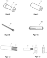
- Figures 8-12 show various embodiments of the securing element 73 as pin-like components.
- Figure 8 represents the securing element 73 as a pin with two fitting sections.
- the first fitting section 732 has a smaller diameter than the second fitting section 733. This allows a Double fitting can be effectively avoided, allowing easy installation in the corresponding openings 88, 89 of the side walls 90, 91.
- the securing element 73 is shown as a bolt. This bolt has a constant diameter over its length.
- the securing element 73 as in Figure 10 is designed as a splint.
- the securing element 73 can be as in Figure 11 be designed as a grooved pin. Thanks to the design of the securing element 73 as a grooved pin, a secure fixation in the direction of the grooved pin axis in the openings of the side walls 90, 91 of the holding unit 12 can be achieved, so that falling out of the openings can be avoided even in the event of strong vibrations.
- the securing element 73 is shown as a pin with a knurling 731, in particular a longitudinal knurling.
- Figure 13 the securing element 73 before the pressing process into the holding unit 12.
- the diameters of the two openings 88 and 89 are adapted to the diameter of the securing element 73 in order to avoid double fits, whereby the opening 89 has a small diameter.
- the openings 89, into which the securing element 73 is inserted last preferably have a smaller diameter than the opening 88, into which the securing element 73 is inserted first.
- a securing element 73 in all design variants can be improved by providing the end of the securing element 73, which is first inserted into the openings of the holding unit 12, with an insertion bevel. This effectively prevents the securing element 73 from tilting during joining.
Landscapes
- Engineering & Computer Science (AREA)
- Chemical & Material Sciences (AREA)
- Combustion & Propulsion (AREA)
- Transportation (AREA)
- Mechanical Engineering (AREA)
- Steering Controls (AREA)
- Clamps And Clips (AREA)
Description
- Die Erfindung betrifft eine Lenksäule für ein Kraftfahrzeug umfassend eine Stelleinheit, in der eine Lenkwelle drehbar gelagert ist, eine Halteeinheit, die mit der Karosserie des Kraftfahrzeugs verbindbar ist und die Stelleinheit trägt, wobei die Stelleinheit relativ zur Halteeinheit verstellbar ist, wenigstens ein Arretierelement, das mit der Halteeinheit zur axialen Arretierung der Stelleinheit beweglich gekoppelt ist, wenigstens ein Federelement, das eine Vorspannkraft auf das Arretierelement ausübt, wenigstens ein Sicherungselement zur Fixierung des Federelements. Weiterhin betrifft die Erfindung ein Verfahren zum Montieren. Eine Lenksäule gemäß dem Oberbegriff des Patentanspruchs 1 ist beispielsweise aus
DE 10 2016 214 709 A1 bekannt. - Generell sind Lenksäulen für Kraftfahrzeuge bekannt, bei denen eine Lenkradposition an die Sitzposition des Fahrers eines Kraftfahrzeugs anpassbar ist. Die Lenksäule weist dazu eine Lenkspindel auf, an der ein Lenkrad befestigt ist. Die Lenksäule ist dabei im Wesentlichen derart verstellbar, dass das Lenkrad durch eine Längenverstellung in Längsrichtung der Lenksäule im Fahrzeuginnenraum positionierbar ist. Zur Fixierung der Lenkspindel mit dem Lenkrad an der gewünschten Position weist die Lenksäule eine Spanneinrichtung auf.
- Eine Lenksäule mit einer Spanneinrichtung ist beispielsweise aus der eingangs genannten
DE 10 2016 214 709 A1 bekannt. Die Lenksäule umfasst hierbei eine Manteleinheit und ein inneres Mantelrohr, in dem eine Lenkspindel drehbar gelagert ist. Das innere Mantelrohr ist in Richtung der Längsachse der Lenkspindel teleskopartig verstellbar und mittels einer lösbaren Spanneinrichtung in unterschiedlichen Lenkradpositionen feststellbar. Die Manteleinheit ist an der Karosserie des Kraftfahrzeugs gehaltert. - Die aus der
DE 10 2016 214 709 A1 bekannte Spanneinrichtung weist ein Arretierelement auf, das mit einem Eingriffsteil formschlüssig verbindbar und in der Manteleinheit verschiebbar angeordnet ist. Das Eingriffsteil ist mit dem inneren Mantelrohr gekoppelt. Ferner weist die Spanneinrichtung einen Nocken und einen Spannbolzen auf, der in der Manteleinheit drehbar gelagert ist. Der Nocken ist dabei mit dem Spannbolzen derart verbunden, dass der Spannbolzen durch eine Rotationsbewegung mit dem Arretierelement zusammenwirkt. Das Arretierelement wird durch die Drehbewegung des Nockens angehoben bzw. abgesenkt. In der Freigabestellung sind das Arretierelement und das Eingriffselement voneinander entkoppelt. Zur Anhebung bzw. Absenkung des Arretierelements weist das Arretierelement eine Nockenbahn auf. Der Nocken wirkt dabei mit der Nockenbahn des Arretierelements zur Fixierung bzw. Lösung der Lenkspindel zusammen. - Zur Vorspannung des Arretierelements weist die Spanneinrichtung ein Federelement auf, das am Arretierelement angreift. Dabei ist das Federelement in einer Halterung derart angeordnet, dass das Federelement mit einem freien Ende mit der Halterung fest verbunden ist.
- Nachteilig an der aus der
DE 10 2016 214 709 A1 vorbekannten Spanneinrichtung ist, dass die Verbindung des Federelements mit der Halterung aufwendig ist, da ein Gewinde in die Halterung geschnitten und das Federelement mit der Halterung verschraubt wird. Dies stellt einen erhöhten Fertigungs- und Montageaufwand dar. Dasselbe gilt für die aus derUS 2008/0236325 A1 bekannte Spanneinrichtung. - Der Erfindung liegt die Aufgabe zu Grunde, eine Lenksäule mit einer verbesserten Spanneinrichtung anzugeben, die einfach und kostengünstig aufgebaut sowie leicht zu montieren ist.
- Erfindungsgemäß wird diese Aufgabe im Hinblick auf die Lenksäule durch den Gegenstand des Patentanspruchs 1 gelöst.
- Konkret wird die Aufgabe durch eine Lenksäule für ein Kraftfahrzeug gelöst, die eine Stelleinheit umfasst, in der eine Lenkwelle drehbar gelagert ist. Die Lenksäule umfasst eine Halteeinheit, die mit der Karosserie des Kraftfahrzeuges verbindbar ist und die Stelleinheit trägt, wobei die Stelleinheit relativ zur Halteeinheit verstellbar ist. Die Lenksäule weist wenigstens ein Arretierelement auf, das mit der Halteeinheit zur axialen Arretierung der Stelleinheit beweglich gekoppelt ist, sowie wenigstens ein Federelement, das eine Vorspannkraft auf das Arretierelement ausübt. Ferner umfasst die Lenksäule wenigstens ein Sicherungselement zur Fixierung des Federelements, wobei das Arretierelement, das Sicherungselement und ein Gegenlager eine Dreipunktanordnung bilden, in der das Federelement positioniert und fixiert ist. Dabei stützt sich das Federelement einerseits am Arretierelement und andererseits am Gegenlager ab. Zwischen dem Arretierelement und dem Gegenlager ist ein Sicherungselement angeordnet, das das Federelement vorspannt.
- Die Erfindung hat den Vorteil, dass es sich hierbei um ein selbstsicherndes System handelt, bei dem das Sicherungselement eine Doppelfunktion erfüllt. Sowohl das Vorspannen als auch das Sichern bzw. Fixieren des Federelements erfolgen durch das Sicherungselement. Somit ist kein zusätzlicher Schraub- bzw. Nietvorgang zum Vorspannen bzw. Fixieren des Federelements erforderlich.
- Das Gegenlager bildet dabei einen ersten Punkt, insbesondere ersten Lagerpunkt oder ersten Haltepunkt der Dreipunktanordnung. Das Arretierelement bildet einen zweiten Punkt, insbesondere zweiten Lagerpunkt oder zweiten Haltepunkt der Dreipunktanordnung. Das Sicherungselement bildet einen dritten Punkt, insbesondere dritten Lagerpunkt oder dritten Haltepunkt der Dreipunktanordnung.
- Das Sicherungselement bzw. allgemein der dritte Punkt der Dreipunktanordnung ist zwischen dem Arretierelement und dem Gegenlager, also zwischen dem zweiten und ersten Punkt der Dreipunktanordnung angeordnet. Das Arretierelement und das Gegenlager, also der zweite und erste Punkt der Dreipunktanordnung bilden eine Linie. Das Sicherungselement bzw. allgemein der dritte Punkt der Dreipunktanordnung ist auf einer Senkrechten angeordnet, die diese Linie schneidet und zwar zwischen dem Arretierelement und dem Gegenlager, also zwischen dem zweiten und ersten Punkt der Dreipunktanordnung. Konkret liegt zumindest die Berührungslinie des Sicherungselements mit dem Federelement außerhalb der Linie zwischen dem Arretierelement und dem Gegenlager, also zwischen dem zweiten und ersten Punkt der Dreipunktanordnung. In
Fig. 7 ist die Berührungslinie des Sicherungselements mit dem Federelement unterhalb der Linie zwischen dem Arretierelement und dem Gegenlager angeordnet, eine andere Anordnung je nach Einbaulage des Federelements ist möglich. Dadurch wird erreicht, dass bspw. im Fall eines geraden Federelements dieses zur Erzeugung der Vorspannkraft ausgelenkt wird. - Das Sicherungselement bzw. allgemein der dritte Punkt der Dreipunktanordnung kann auch direkt auf der Linie angeordnet sein, bspw. wenn das Federelement in der Ruhelage gekrümmt ist.
- Außerdem sind vorzugsweise das Gegenlager, insbesondere das Gegenlager und das Arretierelement einerseits und das Sicherungselement andererseits im montierten Zustand auf entgegengesetzten Seiten des Federelements angeordnet. Mit anderen Worten ist das Federelement zwischen dem Sicherungselement einerseits und dem Gegenlager und dem Arretierelement andererseits angeordnet, insbesondere eingespannt.
- Durch die vorstehend beschriebe Lage der drei Punkte wird bewirkt, dass das Federelement so in die Dreipunktanordnung eingespannt werden kann bzw. eingespannt ist, dass auf das Arretierelement eine Vorspannkraft wirkt, die das Arretierelement in die Arretierstellung zwingt. Die Dreipunktanordnung und das Federelement wirken so zusammen, dass das Federelement im eingespannten Zustand aus der Ruhelage ausgelenkt und im ausgelenkten Zustand fixiert ist. Das Federelement ist im ausgelenkten Zustand elastisch verformt.
- Das Federelement kann im Ruhezustand beispielsweise gerade ausgebildet sein. Die Dreipunktanordnung bedingt dann eine Biegelinie des Federelements, entlang der sich das Federelement im eingespannten Zustand verformt. Im verformten Zustand kann das Federelement kontinuierlich gekrümmt sein. Die Lage der drei Punkte, Arretierelement, Gegenlager und Sicherungselement, relativ zueinander bestimmt die Biegelinie des Federelements und somit die Federkraft, die auf das Arretierelement wirkt.
- Es ist auch möglich, dass das Federelement im Ruhezustand gekrümmt und im eingespannten Zustand in der Dreipunktanordnung zumindest teilweise gestreckt wird. Auch hier wirken die Dreipunktanordnung und das Federelement so zusammen, dass das Arretierelement mit einer Vorspannkraft beaufschlagt wird.
- Generell kann das Federelement als Blattfeder, also als flache, blattförmige Feder ausgebildet sein. Das Federelement kann beispielsweise durch eine Federzunge gebildet sein, die sich an einem Ende verjüngt. Die Federzunge hat insbesondere eine trapezförmige Form, wobei die Basis am Gegenlager und die parallel gegenüber angeordnete Seite bzw. das parallel gegenüber angeordnete Ende der Federzunge am Arretierelement anliegen. Die Basis und die parallel gegenüber angeordnete Seite bilden die Grundseiten der trapezförmigen Federzunge. Die Basis ist länger als die parallel gegenüber angeordnete Seite bzw. das Ende.
- Andere Formen des Federelements sind möglich.
- Zur Montage kann das Federelement mit Hilfe eines Montagewerkzeuges ausgelenkt und in der Dreipunktanordnung positioniert werden, bspw. durch Einschieben. Es ist auch möglich, das Federelement auf dem Arretierelement und dem Gegenlager zu positionieren und auszulenken, so dass das Sicherungselement in die Halteeinheit eingefügt werden kann, um das Federelement in dem vorgespannten Zustand zu sichern und zu fixieren.
- Die Justierung der erforderlichen Vorspannkraft auf das Arretierelement erfolgt dabei durch die Beabstandung zwischen dem Arretierelement und dem Federelement sowie zwischen dem Sicherungselement und dem Federelement.
- Durch das Federelement wird das Arretierelement im montierten Zustand gegen das Eingriffselement vorgespannt. Das Federelement bewirkt somit eine Vorspannung des Arretierelements in Richtung des Eingriffselements. Dadurch wird ein sicheres Eingreifen des Arretierelements in das Eingriffselement ermöglicht. Mit anderen Worten ist durch das Federelement das Arretierelement in die Fixierstellung bzw. Arretierstellung überführbar. Das Federelement spannt das Arretierelement derart vor, dass ein sicheres Schließen des Spannhebels und somit ein sicheres Überführen des Arretierelements in die Fixierstellung erreicht wird.
- Bevorzugte Ausführungsformen der Erfindung sind in den Unteransprüchen angegeben.
- In einer bevorzugten Ausführungsform, weist die Lenksäule wenigstens eine Spannwelle auf, die drehfest mit einem Nocken verbunden ist, der das Arretierelement zum Lösen oder Arretieren der Stelleinheit betätigt. Dabei kann die Spannwelle mit einem Hebel und einer Klemmvorrichtung gekoppelt sein, wobei die Klemmvorrichtung zwischen einer Freigabestellung und einer Fixierstellung positioniert ist. Die Kopplung hat den Vorteil, dass die Klemmvorrichtung beispielsweise als kompakte Nocken- oder Kippstift-Klemmvorrichtung ausgeführt sein kann.
- Das Sicherungselement kann in einer bevorzugten Ausführungsform als stiftartiges Bauteil ausgebildet sein, das mit der Halteeinheit fest verbunden ist. Diese Verbindungsform bringt den Vorteil mit sich, dass sie einfacher und kostengünstiger gegenüber der Fixierung mittels einer Schraube ist. Beispielsweise können Zylinderstifte mit rundem, kreiszylindrischem oder beliebigem Querschnitt verwendet werden. Ferner kann das Sicherungselement auch als Splint, als Stift mit zwei Passabschnitten oder als Passkerbstift gem. ISO 8745 ausgebildet sein.
- In einer vorteilhaften Weiterbildung kann die feste Verbindung des Sicherungselements in der Halteeinheit dadurch realisiert sein, dass das Federelement das Sicherungselement derart mit einer Kraft in radialer Richtung, also in einer Richtung orthogonal zur Längserstreckungsachse des Sicherungselements, beaufschlagt, dass dieses kraftschlüssig an der Halteeinheit gehalten ist. Mit anderen Worten ist das Sicherungselement durch die Vorspannkraft des Federelements in der Halteeinheit gegen ein Herausfallen in Richtung der Längserstreckungsachse gehalten.
- Alternativ oder zusätzlich kann das Sicherungselement in eine Öffnung der Halteeinheit eingepresst sein. In einem solchen Fall kann eine Übermaßpassung zwischen dem Sicherungselement und der Öffnung vorgesehen sein.
- In einer weiteren bevorzugten Ausführungsform ist das Sicherungselement in eine Richtung in die Halteeinheit eingefügt, die winklig, insbesondere orthogonal zur Längsachse des Federelements in die Halteeinheit eingefügt ist. Als Auslenkrichtung wird dabei die Richtung bezeichnet, die orthogonal zur Längslage des Federelements und in die Halteeinheit hinein gerichtet ist. Diese Art der Anordnung des Sicherungselements hat den Vorteil, dass eine sehr gute Kraftübertragung auf das Federelement ermöglicht wird.
- Um Doppelpassungen zu vermeiden, weist die Halteeinheit vorzugsweise eine erste und eine zweite Öffnung auf, wobei die Durchmesser der beiden Öffnungen entsprechend an den Durchmesser des Sicherungselements angepasst sind, wobei eine der beiden Öffnungen einen kleineren Durchmesser aufweist.
- Vorzugsweise wird das Sicherungselement in eine der beiden Öffnungen der Halteinheit eingepresst. Dies ermöglicht eine kostengünstige und schnelle Montage.
- In einer bevorzugten Ausführungsform, weist das Federelement einen Vorsprung auf, der in eine seitliche Aussparung der Halteeinheit eingreift. Dadurch wird vermieden, dass das Federelement bei der Montage falsch herum eingesetzt wird.
- Zur exakten Positionierung des Federelements weist das Gegenlager in einer weiteren bevorzugten Ausführungsform ein Positionierelement auf, das in eine korrespondierende Struktur des Federelements eingreift.
- In einer bevorzugten Ausführungsform weist das Sicherungselement eine Rändelung, insbesondere eine Längsrändelung mit einer Vielzahl von Zähnen auf. Somit sind geringere Einpresskräfte bei der Montage erforderlich. Des Weiteren bietet die Rändelung eine erhöhte Sicherheit gegen Verdrehen.
- Ein nebengeordneter Aspekt der Erfindung betrifft ein Verfahren zum Montieren eines Federelements in eine Lenksäule nach dem Oberbegriff des Patentanspruchs 1, bei dem das Federelement innerhalb einer Dreipunktanordnung positioniert wird und mit einer Montagekraft vorgespannt wird, wobei das Sicherungselement anschließend fest mit der Halteeinheit verbunden wird, um das Federelement im vorgespannten Zustand zu fixieren. Zu den Vorteilen des erfindungsgemäßen Verfahrens wird auf die Ausführungen zu Patentanspruch 1 verwiesen.
- Die feste Verbindung des Sicherungselements in der Halteeinheit kann dadurch realisiert werden, dass das Federelement das Sicherungselement derart mit einer Kraft in radialer Richtung, also in einer Richtung orthogonal zur Längserstreckungsachse des Sicherungselements, beaufschlagt, dass dieses kraftschlüssig an der Halteeinheit gehalten ist.
- Alternativ oder zusätzlich kann das Sicherungselement in eine Öffnung der Halteeinheit eingepresst werden. In einem solchen Fall kann eine Übermaßpassung zwischen dem Sicherungselement und der Öffnung vorgesehen sein. Die Erfindung wird nachstehend mit weiteren Einzelheiten unter Bezug auf die beigefügten Zeichnungen näher erläutert.
- In diesen zeigen
- Figur 1
- eine perspektivische Ansicht einer Lenksäule mit einem Halteelement zur generellen Beschreibung des Aufbaus der Lenksäule als Hintergrundinformation;
- Figur 2
- eine perspektivische Ansicht der Lenksäule gemäß
Figur 1 ohne das Halteelement; - Figur 3
- eine perspektivische Ansicht einer Stelleinheit, einer Spanneinrichtung und einer Feststelleinrichtung der Lenksäule gemäß
Figur 1 ; - Figur 4
- eine perspektivische Explosionsansicht der Stelleinheit und einer Energieabsorptionseinrichtung der Lenksäule gemäß
Figur 1 ; - Figur 5
- eine perspektivische Ansicht der Lenksäule zusammengebauten Zustand nach einem erfindungsgemäßen Ausführungsbeispiel;
- Figur 6
- eine Detailansicht der Spanneinrichtung gemäß
Figur 5 ; - Figur 7
- eine Seitenansicht der Lenksäule gemäß
Figur 5 mit der Spanneinrichtung und der Feststelleinrichtung in einer Fixierstellung des Arretierelements; - Figur 8
- eine perspektivische Ansicht des Sicherungselements als Stift mit zwei Passabschnitten;
- Figur 9
- eine perspektivische Ansicht des Sicherungselements als Bolzen;
- Figur 10
- eine perspektivische Ansicht des Sicherungselements als Splint;
- Figur 11
- eine perspektivische Ansicht des Sicherungselements als Passkerbstift;
- Figur 12
- eine perspektivische Ansicht des Sicherungselements als Stift mit einer Längsrändelung und
- Figur 13
- eine perspektivische Ansicht des Sicherungselements vor dem Einpressen die beiden Öffnungen der Halteeinheit.
-
Figur 1 zeigt eine perspektivische Ansicht einer Lenksäule 10 zur Erläuterung der Einbausituation der relevanten Bauteile. Die allgemeine Einbausituation wird auch im Zusammenhang mit dem erfindungsgemäßen Ausführungsbeispiel gemäßFig. 5-13 offenbart. Die Lenksäule 10 umfasst eine Stelleinheit 11, eine Halteeinheit 12 und eine Spanneinrichtung 20. Die Lenksäule 10 ist durch die Halteeinheit 12 an einer Karosserie eines nicht dargestellten Kraftfahrzeugs befestigbar. Die Halteeinheit 12 weist ein Halteelement 54 in Form einer Konsole auf, durch die die Lenksäule 10 mit der Karosserie des Kraftfahrzeugs verbindbar ist. Das Halteelement 54 umfasst zur Verbindung mit der Karosserie Befestigungsmittel 54a. Das Halteelement 54 weist des Weiteren Seitenwangen 55, 56 auf, die zueinander beabstandet sind. Die Seitenwangen 55, 56 sind dabei derart zueinander angeordnet, dass die Halteeinheit 12 zwischen den Seitenwangen 55, 56 aufgenommen ist. Die Stelleinheit 11 ist in der Halteeinheit 12 angeordnet. - Die Stelleinheit 11 umfasst eine Lenkspindel 52 und ein Mantelrohr 51. Die Lenkspindel 52 und das Mantelrohr 51 weisen eine gemeinsame Längsachse L auf. Die Lenkspindel 52 ist dabei im Mantelrohr 51 um die Längsachse L drehbar gelagert angeordnet. Die Lenkspindel 52 weist ein hinteres Ende 53 auf, an dem ein nicht dargestelltes Lenkrad auf der Lenkspindel 52 anbringbar ist. Das Mantelrohr 51 ist in einer Aufnahme der Halteeinheit 12 gehaltert.
- Wie in
Figur 2 gezeigt, weist die Spanneinrichtung 20 einen Spannhebel 21, eine Spannwelle 22 und einen Nocken 23 auf. Der Spannhebel 21 ist mit der Spannwelle 22 drehfest verbunden. Die Spannwelle 22 ist quer zur Längsachse L durch Langlöcher 57 in den einander gegenüberliegenden Seitenwangen 55, 56 und durch eine Durchgangsöffnung der Halteeinheit 12 hindurchgeführt. Die Spanneinrichtung 20 umfasst hierbei eine im Allgemeinen bekannte Spannmechanik mit einer Kippstiftanordnung 24 und einer Stützscheibe 25. - Die Kippstiftanordnung 24 ist mit der Spannwelle 22 drehfest verbunden. Ferner ist die Stützscheibe 25 der Kippstiftanordnung 24 gegenüberliegend drehfest mit der Seitenwange 55 verbunden. Durch eine Drehung des Spannhebels 21 und der damit verbundenen Spannwelle 22 wird die Stützscheibe 25 relativ zu dem Spannhebel 21 und der Spannwelle 22 axial verlagert. Die Stützscheibe 25 wird dadurch von außen gegen die Seitenwange 55 angepresst. Die Spannwelle 22 ist an der gegenüber angeordneten Seitenwange 56 axial verschiebefest gelagert, beispielsweise durch eine als Widerlager wirkende Sechskantmutter, die ein Innengewinde aufweist und auf ein Außengewinde der Spannwelle 22 aufgeschraubt ist. Werden daher die beiden Seitenwangen 55, 56 gegeneinander bewegt, wird die dazwischen angeordnete Halteeinheit 12 kraftschlüssig festgeklemmt. Anstelle der gezeigte Kippstiftanordnung 24, 25 können auch andere Mechanismen zur Umsetzung der Drehbewegung in eine Klemmbewegung zum Einsatz kommen, wie beispielsweise ein Keilscheibe-Nockenscheibe-Klemmvorrichtung.
- Gemäß
Figur 3 ist eine perspektivische Ansicht einer Stelleinheit 11, wie vorstehend beschrieben gezeigt. Ferner zeigtFigur 3 eine Feststelleinrichtung 30, eine Koppelvorrichtung 60 und eine Energieabsorptionseinrichtung 80. - Die Feststelleinrichtung 30 weist ein Arretierelement 31 und ein Eingriffselement 33 auf. Das Arretierelement 31 ist in Richtung der Längsachse L in der Halteeinheit 12 verschiebefest gelagert. In der Höhenrichtung H ist das Arretierelement 31 zur Einstellung der Feststellposition oder der Freigabeposition des Spannhebels 21 höhenverstellbar gelagert. Mit anderen Worten ist das Arretierelement 31 in der Halteeinheit 12 derart angeordnet, dass das Arretierelement 31 in der Halteeinheit 12 in der Höhenrichtung H verschiebbar ist. Das Eingriffselement 33 ist über eine Energieabsorptionseinrichtung 80 mit dem Mantelrohr 51 verbunden. Das Arretierelement 31 und das Eingriffselement 33 weisen Formschlussmittel 31a, 33a auf. Die Formschlussmittel 31a, 33a sind durch eine Hubbewegung des Arretierelements 31 formschlüssig in Eingriff bringbar.
- In
Figur 4 weist das Eingriffselement 33 ein Verbindungsteil 71 auf. Das Verbindungsteil 71 bildet ein separates Teil, das durch eine Koppelvorrichtung 60 mit dem Eingriffselement 33 verbunden ist. Hierzu greift ein Bolzen 61 der Koppelvorrichtung 60 in eine Bohrung 72 des Verbindungsteils 71 ein. Die Koppelvorrichtung 60 ist mit dem Eingriffselement 33 fest verbunden. Die Betätigung der Koppelvorrichtung 60 ermöglicht ein Lösen der mechanischen Verbindung zwischen dem Eingriffselement 33 und dem Verbindungsteil 71, in dem ein Bolzen 61 der Koppelvorrichtung 60 mittels einer pyrotechnischen Treibladung von einer ausgefahrenen Position in eine zurückgezogene Position überführt wird. Dabei ist das Verbindungsteil 71 vom Eingriffselement 33 getrennt, wobei das Verbindungsteil 71 und das Eingriffselement 33 in Längsrichtung L unabhängig voneinander bewegbar sind. Wie inFigur 4 gezeigt, sind Energieabsorptionselemente 64, 66 im Innenprofil 63 beabstandet zueinander angeordnet. Die Energieabsorptionselemente 64, 66 sind hierbei jeweils als U-förmiger Biegedraht, insbesondere Biegestreifen ausgestaltet. Das jeweilige Energieabsorptionselement 64, 66 ist mit einem ersten Schenkel über eine Umbiegung von 180° mit einem zweiten Schenkel verbunden. Am Ende des zweiten Schenkels ist jeweils ein Mitnehmerhaken 64b, 66b durch eine Umbiegung gegen den ersten Schenkel ausgebildet. Die Energieabsorptionselemente 64, 66 können als Stanzteile ausgebildet sein. Das Verbindungsteil 71 weist einen Zapfen 74 auf, der mit dem Mitnehmerhaken 64b in Wirkeingriff steht und in die durch die Umbiegung und den Mitnehmerhaken 64b gebildete ösenförmige Ausnehmung 64a eingreift. Das Eingriffselement 33 weist einen Zapfen 77 auf, der mit dem Mitnehmerhaken 66b in Wirkeingriff steht und in die durch die Umbiegung und den Mitnehmerhaken 66b gebildete ösenförmige Ausnehmung 66a eingreift. - In einem ersten Crashfall, in dem das Eingriffselement 33 mit dem Verbindungselement 71 gekoppelt ist, werden beide Energieabsorptionselemente 64, 66 gleichzeitig deformiert zur Bereitstellung eines hohen Crashniveaus. In einem zweiten Crashfall, in dem das Eingriffselement 33 von dem Verbindungselement 71 entkoppelt ist, wird nur das Energieabsorptionselement 66 deformiert und das Energieabsorptionselement 64 bleibt undeformiert zur Bereitstellung eines niedrigen Crashniveaus.
-
Figur 5 zeigt eine perspektivische Ansicht der Lenksäule 10 im zusammengebauten Zustand nach einem erfindungsgemäßen Ausführungsbeispiel. Die im Zusammenhang mit denFiguren 1-4 erläuterten Bauteilen sind bei der Lenksäule 10 gemäßFigur 5 ebenfalls verbaut. Hierzu wird auf die obigen Ausführungen verwiesen. - In
Figur 6 ist eine Detailansicht der Spanneinrichtung 20 gemäßFigur 5 abgebildet. Zur Vorspannung des Arretierelements 31 weist die Halteeinheit 12 ein Federelement 35 auf, das das Arretierelement 31 gegen das Eingriffselement 33 presst. - Das Federelement 35 ist als Blattfeder, insbesondere als Federzunge mit einer länglichen Bauform ausgebildet. Zu den Einzelheiten der Federzunge wird auf die Beschreibungseinleitung verwiesen. Das der Basis gegenüberangeordnete Ende der Federzunge bzw. des Federelements 35 greift am Arretierelement 31, insbesondere an einem nachstehend näher beschriebenen Stützabschnitt 82 an. Dazu weist das Ende einen abgekanteten Abschnitt auf, der linienförmig am Stützabschnitt 82 bzw. allgemein am Arretierelement 31 anliegt.
- Das Federelement 35 weist im Bereich der Basis, d.h. nahe am Gegenlager 85 einen Vorsprung auf, der in eine seitliche Aussparung der Halteeinheit 12 eingreift, um eine Falschmontage zu vermeiden.
- Das Federelement 35 kann aus Federstahl oder einem anderem Material gebildet sein.
- Im eingespannten Zustand ist das Federelement 35 gekrümmt.
- Das Federelement 35 ist in einer Dreipunktanordnung angeordnet, die aus dem Arretierelement 31, einem Sicherungselement 73 und einem Gegenlager 85 gebildet ist. Das Federelement 35 stützt sich einerseits an dem Stützabschnitt 82, der Teil des Arretierelements 31 ist, und andererseits an dem Gegenlager 85 ab. Der Stützabschnitt 82 bildet einen ersten Absatz mit einer geraden Auflagefläche für das eine Ende des Federelements 35. Der erste Absatz ist auf der dem Eingriffselement 33 gegenüber angeordneten Seite des Arretierelements 31 ausgebildet. Das Gegenlager 85 bildet einen zweiten Absatz oder eine Schulter, in die die Basis, d.h. das andere Ende des Federelements 35 eingepasst ist. Mit anderen Worten lagert das Gegenlager 85 das Federelement in axialer Richtung, d.h. in einer Richtung entlang der Längsachse des Federelements 35, um ein Verschieben des Federelements 35 zu vermeiden. Zudem lagert das Gegenlager 85 das Federelement 35 in Querrichtung, d.h. in einer Richtung quer zur Längsachse des Federelements 35, um die Vorspannkraft in die Halteeinheit 12 einzuleiten.
- Das Sicherungselement 73 ist auf der Seite des Federelements 35 entgegengesetzt zum Gegenlager 85 und dem Arretierelement 31 angeordnet und biegt das Federelement 35 durch.
- Die Dreipunktanordnung kann als eine Lagerung des Federelements 35 an drei Positionen betrachtet werden, die eine kontinuierliche Durchbiegung des Federelements 35 ermöglicht (
Figur 7 ). - Das Halteelement 12 umfasst zwei parallel angeordnete Seitenwände 90 und 91, wobei die Seitenwand 91 einen Vorsprung 92 aufweist. Die Seitenwände 90 und 91 weisen zwei Öffnungen 88, 89 auf. Zwischen dem Arretierelement 31 und dem Gegenlager 85 ist das Sicherungselement 73 in die beiden Seitenwände 90 und 91 derart angeordnet, dass sich das Sicherungselement 73 dabei oberhalb des Federelements 35 befindet und das Federelement 73 vorspannt bzw. fixiert. Das Sicherungselement 73 ist dabei winklig, insbesondere orthogonal zur Längsachse des Federelements 35 in die beiden Öffnungen 88, 89 eingefügt. Die orthogonale Anordnung des Sicherungselements 73 ermöglicht eine gute Kraftübertragung und einfache Montage.
- Ein kegelförmiges Positionierelement 87 greift in eine korrespondierende Struktur des Federelements 35 ein, um das Federelement 35 exakt innerhalb der Dreipunktanordnung zu positionieren. Das Positionierelement 87 befindet sich im Bereich des Gegenlagers 85 und ragt durch eine Öffnung 351 des Federelements 35 hindurch.
- Das Federelement 35 weist einen Vorsprung 352 auf, welche in eine Ausnehmung der Halteeinheit 12 eingreift, wobei der Vorsprung am Federelement 35 derart unsymmetrisch angeordnet ist, dass das Federelement 35 lediglich in einer einzigen Position an der Halteeinheit 12 montierbar ist. Somit kann auf einfache Art und Weise ein Fehlverbau verhindert werden.
- Gemäß
Figur 7 stehen das Arretierelement 31 und das Eingriffselement 33 formschlüssig in Eingriff. Die Fixierstellung der Arretierelements 31 entspricht dabei der Feststellposition der Spanneinrichtung 20. In der Fixierstellung des Arretierelements 31 ist das Arretierelement 31 mit dem Eingriffselement 33 in Richtung der Längsachse L verschiebefest, insbesondere formschlüssig verbunden. In der Freigabeposition der Spanneinrichtung 20 ist das Arretierelement 31 vom Eingriffselement 33 entkoppelt, das einer Lösestellung des Arretierelements 31 entspricht. Durch das Federelement 35 wird eine Vorspannkraft auf das Arretierelement 31 ausgeübt. Durch die Drehung des Spannhebels 21 wirkt der Nocken 23 mit einer Kulissenbahn 32 derart zusammen, dass das Arretierelement 31 quer zur Längsachse L angehoben bzw. abgesenkt wird. - Die
Figuren 8-12 zeigen verschiedene Ausführungsbeispiele des Sicherungselements 73 als stiftartige Bauteile.Figur 8 stellt das Sicherungselement 73 als Stift mit zwei Passabschnitten dar. Bevorzugt weist der erste Passabschnitt 732 einen geringen Durchmesser auf als der zweite Passabschnitt 733. Dadurch kann eine Doppelpassung wirksam vermieden werden, so dass eine einfache Montage in den entsprechenden Öffnungen 88, 89 der Seitenwände 90, 91 ermöglicht ist. - In
Figur 9 wird das Sicherungselement 73 als Bolzen dargestellt. Dieser Bolzen weist einen über seine Länge konstanten Durchmesser auf. - Ferner ist es möglich, das das Sicherungselement 73 wie in
Figur 10 als Splint ausgebildet ist. - In einer weiteren Ausführungsform kann das Sicherungselement 73 wie in
Figur 11 als Passkerbstift ausgebildet sein. Dank der Ausbildung des Sicherungselements 73 als Passkerbstift kann eine sichere Fixierung in Richtung der Passkerbstiftachse in den Öffnungen der Seitenwänden 90, 91 der Halteeinheit 12 realisiert werden, so dass auch bei starken Vibrationen ein Herausfallen aus den Öffnungen vermieden werden kann. - In den
Figuren 12 und 13 wird das Sicherungselement 73 als Stift mit einer Rändelung 731, insbesondere einer Längsrändelung dargestellt. Dabei zeigtFigur 13 das Sicherungselement 73 vor dem Einpressvorgang in die Halteeinheit 12. Die Durchmesser der beiden Öffnungen 88 und 89 sind dabei dem Durchmesser des Sicherungselements 73 angepasst um Doppelpassungen zu vermeiden, wobei die Öffnung 89 einen kleinen Durchmesser vorweist. - Die Öffnungen 89, in die das Sicherungselement 73 zuletzt gefügt wird, weist bevorzugt einen kleineren Durchmesser auf als die Öffnung 88, in die das Sicherungselement 73 zuerst eingeführt wird.
- Generell kann ein Sicherungselement 73 in sämtlichen Ausführungsvarianten dadurch verbessert werden, dass das Ende des Sicherungselements 73 welches zuerst in die Öffnungen der Halteeinheit 12 eingeführt wird, eine Einführfase aufweist. Dadurch kann beim Fügen ein Verkanten des Sicherungselements 73 wirksam vermieden wird.
Claims (10)
- Lenksäule (10) für ein Kraftfahrzeug umfassend- eine Stelleinheit (11), in der eine Lenkwelle (52) drehbar gelagert ist,- eine Halteeinheit (12), die mit der Karosserie des Kraftfahrzeugs verbindbar ist und die Stelleinheit (11) trägt, wobei die Stelleinheit (11) relativ zur Halteeinheit (12) verstellbar ist,- wenigstens ein Arretierelement (31), das mit der Halteeinheit (12) zur axialen Arretierung der Stelleinheit (11) beweglich gekoppelt ist,- wenigstens ein Federelement (35), das eine Vorspannkraft auf das Arretierelement (31) ausübt,- wenigstens ein Sicherungselement (73) zur Fixierung des Federelements (35),dadurch gekennzeichnet, dass
das Arretierelement (31), das Sicherungselement (73) und ein Gegenlager (85) eine Dreipunktanordnung bilden, in der das Federelement (35) fixiert ist, wobei das Federelement (35) einerseits am Arretierelement (31) und andererseits am Gegenlager (85) abgestützt ist, wobei das Sicherungselement (73) zwischen dem Arretierelement (31) und dem Gegenlager (85) angeordnet ist und das Federelement (35) vorspannt. - Lenksäule nach Anspruch 1,
dadurch gekennzeichnet, dass
wenigstens eine Spannwelle (22) drehfest mit einem Nocken (23) verbunden ist, der das Arretierelement (31) zum Lösen oder Arretieren der Stelleinheit (11) betätigt. - Lenksäule nach einem der vorhergehenden Ansprüche,
dadurch gekennzeichnet, dass
das Sicherungselement (73) als stiftartiges Bauteil ausgebildet ist, das mit der Halteeinheit (12) fest verbunden ist. - Lenksäule nach einem der vorhergehenden Ansprüche,
dadurch gekennzeichnet, dass
das Sicherungselement (73) unter einem Winkel, insbesondere orthogonal zur Längsachse des Federelements (35) angeordnet ist. - Lenksäule nach einem der vorhergehenden Ansprüche,
dadurch gekennzeichnet, dass
die Halteeinheit (12) eine erste Öffnung (88) und eine zweite Öffnung (89) aufweist, wobei die Durchmesser der beiden Öffnungen (88, 89) entsprechend an den Durchmesser des Sicherungselements (73) angepasst sind, wobei eine der beiden Öffnungen (88, 89) einen kleineren Durchmesser aufweist. - Lenksäule nach Anspruch 5,
dadurch gekennzeichnet, dass
das Sicherungselement (73) in wenigstens eine der beiden Öffnungen (88, 89) der Halteeinheit (12) eingepresst ist. - Lenksäule nach Anspruch 1,
dadurch gekennzeichnet, dass
das Federelement (35) einen Vorsprung aufweist, der in eine Aussparung der Halteeinheit (12) eingreift. - Lenksäule nach Anspruch 1,
dadurch gekennzeichnet, dass
das Gegenlager (85) ein Positionierelement (87) aufweist, das in eine korrespondierende Struktur des Federelements (35) eingreift, um die Position des Federelements (35) festzulegen. - Lenksäule nach einen der vorrangehenden Ansprüchen,
dadurch gekennzeichnet, dass das Sicherungselement (73) eine Rändelung aufweist. - Verfahren zum Montieren eines Federelements (35) in eine Lenksäule nach Anspruch 1, bei dem- das Federelement (35) innerhalb der Dreipunktanordnung positioniert und mit einer Montagekraft vorgespannt wird;- das Sicherungselement (73) anschließend fest mit der Halteeinheit (12) verbunden wird, um das Federelement (35) im vorgespannten Zustand zu fixieren.
Applications Claiming Priority (2)
| Application Number | Priority Date | Filing Date | Title |
|---|---|---|---|
| DE102018131918.5A DE102018131918A1 (de) | 2018-12-12 | 2018-12-12 | Lenksäule für ein Kraftfahrzeug und ein Verfahren zum Montieren |
| PCT/EP2019/084389 WO2020120456A1 (de) | 2018-12-12 | 2019-12-10 | Lenksäule für ein kraftfahrzeug und ein verfahren zum montieren |
Publications (2)
| Publication Number | Publication Date |
|---|---|
| EP3894301A1 EP3894301A1 (de) | 2021-10-20 |
| EP3894301B1 true EP3894301B1 (de) | 2024-09-11 |
Family
ID=69061267
Family Applications (1)
| Application Number | Title | Priority Date | Filing Date |
|---|---|---|---|
| EP19828986.0A Active EP3894301B1 (de) | 2018-12-12 | 2019-12-10 | Lenksäule für ein kraftfahrzeug und ein verfahren zum montieren |
Country Status (5)
| Country | Link |
|---|---|
| US (1) | US11667323B2 (de) |
| EP (1) | EP3894301B1 (de) |
| CN (1) | CN113226889B (de) |
| DE (1) | DE102018131918A1 (de) |
| WO (1) | WO2020120456A1 (de) |
Citations (1)
| Publication number | Priority date | Publication date | Assignee | Title |
|---|---|---|---|---|
| US20080236325A1 (en) * | 2007-03-30 | 2008-10-02 | Delphi Technologies, Inc. | Lock mechanism for an adjustable steering column assembly |
Family Cites Families (10)
| Publication number | Priority date | Publication date | Assignee | Title |
|---|---|---|---|---|
| GB2311839A (en) | 1996-04-02 | 1997-10-08 | Nastech Europ Ltd | A reach and rake adjustable steering column device |
| US7174804B2 (en) * | 2002-12-03 | 2007-02-13 | Associated Spring Raymond | Positioning mechanism for tilt steering |
| DE102008016742B4 (de) * | 2008-03-31 | 2010-01-14 | Thyssenkrupp Presta Ag | Lenksäule für ein Kraftfahrzeug |
| CN103754254B (zh) * | 2014-02-13 | 2016-02-10 | 安徽江淮汽车股份有限公司 | 四向可调的溃缩吸能转向管柱 |
| DE102014108577B3 (de) * | 2014-06-18 | 2015-09-10 | Thyssenkrupp Presta Ag | Lenksäule für ein Kraftfahrzeug |
| DE102015204894A1 (de) * | 2015-03-18 | 2016-09-22 | Thyssenkrupp Ag | Lenksäule für ein Kraftfahrzeug |
| CN105711637B (zh) | 2016-04-07 | 2017-11-28 | 重庆长安汽车股份有限公司 | 一种转向管柱角度调节机构 |
| DE102016210833A1 (de) * | 2016-06-17 | 2017-12-21 | Thyssenkrupp Ag | Lenksäule für ein Kraftfahrzeug |
| DE102016214709B4 (de) | 2016-08-09 | 2020-12-31 | Thyssenkrupp Ag | Lenksäule für ein Kraftfahrzeug |
| DE102018128119A1 (de) * | 2018-11-09 | 2020-05-14 | Trw Automotive Gmbh | Feststelleinrichtung für eine verstellbare Lenksäulenbaugruppe |
-
2018
- 2018-12-12 DE DE102018131918.5A patent/DE102018131918A1/de not_active Withdrawn
-
2019
- 2019-12-10 US US17/295,711 patent/US11667323B2/en active Active
- 2019-12-10 CN CN201980083846.7A patent/CN113226889B/zh active Active
- 2019-12-10 EP EP19828986.0A patent/EP3894301B1/de active Active
- 2019-12-10 WO PCT/EP2019/084389 patent/WO2020120456A1/de not_active Ceased
Patent Citations (1)
| Publication number | Priority date | Publication date | Assignee | Title |
|---|---|---|---|---|
| US20080236325A1 (en) * | 2007-03-30 | 2008-10-02 | Delphi Technologies, Inc. | Lock mechanism for an adjustable steering column assembly |
Also Published As
| Publication number | Publication date |
|---|---|
| WO2020120456A1 (de) | 2020-06-18 |
| US20210387662A1 (en) | 2021-12-16 |
| DE102018131918A1 (de) | 2020-06-18 |
| US11667323B2 (en) | 2023-06-06 |
| EP3894301A1 (de) | 2021-10-20 |
| CN113226889B (zh) | 2023-05-26 |
| CN113226889A (zh) | 2021-08-06 |
Similar Documents
| Publication | Publication Date | Title |
|---|---|---|
| EP3698055B1 (de) | Toleranzausgleichsanordnung | |
| EP2512899B1 (de) | Lenksäule für ein kraftfahrzeug | |
| EP2184029B1 (de) | Dehnschraube zur Zahnregulierung | |
| EP1590226B1 (de) | Klemmvorrichtung für lenksäule | |
| EP3180228B1 (de) | Lenksäule für ein kraftfahrzeug | |
| EP1910148B1 (de) | Verstellbare lenksäule für ein kraftfahrzeug | |
| DE102015223485B4 (de) | Höheneinsteller für einen fahrzeugsitz, fahrzeugsitz | |
| EP1525130A1 (de) | Positionseinstellvorrichtung für kraftfahrzeuglenksäulen | |
| EP2500587A1 (de) | Befestigungsvorrichtung zur Anordnung an einer Montageschiene | |
| EP3586018B1 (de) | Befestigungsvorrichtung und befestigungsbaugruppe | |
| EP3436329B1 (de) | Lenksäule für ein kraftfahrzeug | |
| EP4039897A1 (de) | Wandhalterung | |
| EP1513717B1 (de) | Sicherheitsvorrichtung zum arretieren eines verstellbaren anschlussteils | |
| DE102017115276B4 (de) | Verriegelungsvorrichtung sowie Lenksäulenbaugruppe | |
| WO2009153166A1 (de) | Klemmvorrichtung zur lagefixierung einer verstellbaren fahrzeuglenksäule | |
| EP1382509B1 (de) | Lenksäule | |
| DE112021002299B4 (de) | Lenksäule eines fahrzeugs | |
| EP3802276B1 (de) | Lenksäule für ein kraftfahrzeug | |
| DE102011110642B4 (de) | Beschlagbaugruppe | |
| DE102018131918A1 (de) | Lenksäule für ein Kraftfahrzeug und ein Verfahren zum Montieren | |
| EP1901953B1 (de) | Klemmvorrichtung für eine lenksäule | |
| DE102010050015B4 (de) | Feststellvorrichtung für verstellbare Kraftfahrzeuglenksäule | |
| DE102019005341A1 (de) | Positionierungseinrichtung zur Anordnung eines ersten Bauteils relativ zu einem weiteren Bauteil eines Kraftwagens | |
| WO2020064646A1 (de) | Verstellbare lenksäule | |
| DE102018202199A1 (de) | Beschlaganordnung mit Blockiereinrichtung |
Legal Events
| Date | Code | Title | Description |
|---|---|---|---|
| STAA | Information on the status of an ep patent application or granted ep patent |
Free format text: STATUS: UNKNOWN |
|
| STAA | Information on the status of an ep patent application or granted ep patent |
Free format text: STATUS: THE INTERNATIONAL PUBLICATION HAS BEEN MADE |
|
| PUAI | Public reference made under article 153(3) epc to a published international application that has entered the european phase |
Free format text: ORIGINAL CODE: 0009012 |
|
| STAA | Information on the status of an ep patent application or granted ep patent |
Free format text: STATUS: REQUEST FOR EXAMINATION WAS MADE |
|
| 17P | Request for examination filed |
Effective date: 20210712 |
|
| AK | Designated contracting states |
Kind code of ref document: A1 Designated state(s): AL AT BE BG CH CY CZ DE DK EE ES FI FR GB GR HR HU IE IS IT LI LT LU LV MC MK MT NL NO PL PT RO RS SE SI SK SM TR |
|
| DAV | Request for validation of the european patent (deleted) | ||
| DAX | Request for extension of the european patent (deleted) | ||
| STAA | Information on the status of an ep patent application or granted ep patent |
Free format text: STATUS: EXAMINATION IS IN PROGRESS |
|
| 17Q | First examination report despatched |
Effective date: 20220711 |
|
| GRAP | Despatch of communication of intention to grant a patent |
Free format text: ORIGINAL CODE: EPIDOSNIGR1 |
|
| STAA | Information on the status of an ep patent application or granted ep patent |
Free format text: STATUS: GRANT OF PATENT IS INTENDED |
|
| INTG | Intention to grant announced |
Effective date: 20240430 |
|
| GRAS | Grant fee paid |
Free format text: ORIGINAL CODE: EPIDOSNIGR3 |
|
| GRAA | (expected) grant |
Free format text: ORIGINAL CODE: 0009210 |
|
| STAA | Information on the status of an ep patent application or granted ep patent |
Free format text: STATUS: THE PATENT HAS BEEN GRANTED |
|
| AK | Designated contracting states |
Kind code of ref document: B1 Designated state(s): AL AT BE BG CH CY CZ DE DK EE ES FI FR GB GR HR HU IE IS IT LI LT LU LV MC MK MT NL NO PL PT RO RS SE SI SK SM TR |
|
| REG | Reference to a national code |
Ref country code: GB Ref legal event code: FG4D Free format text: NOT ENGLISH |
|
| REG | Reference to a national code |
Ref country code: CH Ref legal event code: EP |
|
| REG | Reference to a national code |
Ref country code: DE Ref legal event code: R096 Ref document number: 502019012127 Country of ref document: DE |
|
| REG | Reference to a national code |
Ref country code: IE Ref legal event code: FG4D Free format text: LANGUAGE OF EP DOCUMENT: GERMAN |
|
| REG | Reference to a national code |
Ref country code: DE Ref legal event code: R084 Ref document number: 502019012127 Country of ref document: DE |
|
| REG | Reference to a national code |
Ref country code: LT Ref legal event code: MG9D |
|
| PG25 | Lapsed in a contracting state [announced via postgrant information from national office to epo] |
Ref country code: NO Free format text: LAPSE BECAUSE OF FAILURE TO SUBMIT A TRANSLATION OF THE DESCRIPTION OR TO PAY THE FEE WITHIN THE PRESCRIBED TIME-LIMIT Effective date: 20241211 |
|
| REG | Reference to a national code |
Ref country code: NL Ref legal event code: MP Effective date: 20240911 |
|
| PG25 | Lapsed in a contracting state [announced via postgrant information from national office to epo] |
Ref country code: GR Free format text: LAPSE BECAUSE OF FAILURE TO SUBMIT A TRANSLATION OF THE DESCRIPTION OR TO PAY THE FEE WITHIN THE PRESCRIBED TIME-LIMIT Effective date: 20241212 Ref country code: FI Free format text: LAPSE BECAUSE OF FAILURE TO SUBMIT A TRANSLATION OF THE DESCRIPTION OR TO PAY THE FEE WITHIN THE PRESCRIBED TIME-LIMIT Effective date: 20240911 |
|
| PG25 | Lapsed in a contracting state [announced via postgrant information from national office to epo] |
Ref country code: BG Free format text: LAPSE BECAUSE OF FAILURE TO SUBMIT A TRANSLATION OF THE DESCRIPTION OR TO PAY THE FEE WITHIN THE PRESCRIBED TIME-LIMIT Effective date: 20240911 |
|
| PG25 | Lapsed in a contracting state [announced via postgrant information from national office to epo] |
Ref country code: LV Free format text: LAPSE BECAUSE OF FAILURE TO SUBMIT A TRANSLATION OF THE DESCRIPTION OR TO PAY THE FEE WITHIN THE PRESCRIBED TIME-LIMIT Effective date: 20240911 |
|
| PG25 | Lapsed in a contracting state [announced via postgrant information from national office to epo] |
Ref country code: HR Free format text: LAPSE BECAUSE OF FAILURE TO SUBMIT A TRANSLATION OF THE DESCRIPTION OR TO PAY THE FEE WITHIN THE PRESCRIBED TIME-LIMIT Effective date: 20240911 |
|
| PG25 | Lapsed in a contracting state [announced via postgrant information from national office to epo] |
Ref country code: RS Free format text: LAPSE BECAUSE OF FAILURE TO SUBMIT A TRANSLATION OF THE DESCRIPTION OR TO PAY THE FEE WITHIN THE PRESCRIBED TIME-LIMIT Effective date: 20241211 Ref country code: ES Free format text: LAPSE BECAUSE OF FAILURE TO SUBMIT A TRANSLATION OF THE DESCRIPTION OR TO PAY THE FEE WITHIN THE PRESCRIBED TIME-LIMIT Effective date: 20240911 |
|
| PG25 | Lapsed in a contracting state [announced via postgrant information from national office to epo] |
Ref country code: RS Free format text: LAPSE BECAUSE OF FAILURE TO SUBMIT A TRANSLATION OF THE DESCRIPTION OR TO PAY THE FEE WITHIN THE PRESCRIBED TIME-LIMIT Effective date: 20241211 Ref country code: NO Free format text: LAPSE BECAUSE OF FAILURE TO SUBMIT A TRANSLATION OF THE DESCRIPTION OR TO PAY THE FEE WITHIN THE PRESCRIBED TIME-LIMIT Effective date: 20241211 Ref country code: LV Free format text: LAPSE BECAUSE OF FAILURE TO SUBMIT A TRANSLATION OF THE DESCRIPTION OR TO PAY THE FEE WITHIN THE PRESCRIBED TIME-LIMIT Effective date: 20240911 Ref country code: HR Free format text: LAPSE BECAUSE OF FAILURE TO SUBMIT A TRANSLATION OF THE DESCRIPTION OR TO PAY THE FEE WITHIN THE PRESCRIBED TIME-LIMIT Effective date: 20240911 Ref country code: GR Free format text: LAPSE BECAUSE OF FAILURE TO SUBMIT A TRANSLATION OF THE DESCRIPTION OR TO PAY THE FEE WITHIN THE PRESCRIBED TIME-LIMIT Effective date: 20241212 Ref country code: FI Free format text: LAPSE BECAUSE OF FAILURE TO SUBMIT A TRANSLATION OF THE DESCRIPTION OR TO PAY THE FEE WITHIN THE PRESCRIBED TIME-LIMIT Effective date: 20240911 Ref country code: ES Free format text: LAPSE BECAUSE OF FAILURE TO SUBMIT A TRANSLATION OF THE DESCRIPTION OR TO PAY THE FEE WITHIN THE PRESCRIBED TIME-LIMIT Effective date: 20240911 Ref country code: BG Free format text: LAPSE BECAUSE OF FAILURE TO SUBMIT A TRANSLATION OF THE DESCRIPTION OR TO PAY THE FEE WITHIN THE PRESCRIBED TIME-LIMIT Effective date: 20240911 |
|
| PG25 | Lapsed in a contracting state [announced via postgrant information from national office to epo] |
Ref country code: NL Free format text: LAPSE BECAUSE OF FAILURE TO SUBMIT A TRANSLATION OF THE DESCRIPTION OR TO PAY THE FEE WITHIN THE PRESCRIBED TIME-LIMIT Effective date: 20240911 |
|
| PG25 | Lapsed in a contracting state [announced via postgrant information from national office to epo] |
Ref country code: IS Free format text: LAPSE BECAUSE OF FAILURE TO SUBMIT A TRANSLATION OF THE DESCRIPTION OR TO PAY THE FEE WITHIN THE PRESCRIBED TIME-LIMIT Effective date: 20250111 Ref country code: PT Free format text: LAPSE BECAUSE OF FAILURE TO SUBMIT A TRANSLATION OF THE DESCRIPTION OR TO PAY THE FEE WITHIN THE PRESCRIBED TIME-LIMIT Effective date: 20250113 |
|
| PG25 | Lapsed in a contracting state [announced via postgrant information from national office to epo] |
Ref country code: RO Free format text: LAPSE BECAUSE OF FAILURE TO SUBMIT A TRANSLATION OF THE DESCRIPTION OR TO PAY THE FEE WITHIN THE PRESCRIBED TIME-LIMIT Effective date: 20240911 Ref country code: SM Free format text: LAPSE BECAUSE OF FAILURE TO SUBMIT A TRANSLATION OF THE DESCRIPTION OR TO PAY THE FEE WITHIN THE PRESCRIBED TIME-LIMIT Effective date: 20240911 |
|
| PG25 | Lapsed in a contracting state [announced via postgrant information from national office to epo] |
Ref country code: EE Free format text: LAPSE BECAUSE OF FAILURE TO SUBMIT A TRANSLATION OF THE DESCRIPTION OR TO PAY THE FEE WITHIN THE PRESCRIBED TIME-LIMIT Effective date: 20240911 |
|
| PG25 | Lapsed in a contracting state [announced via postgrant information from national office to epo] |
Ref country code: PL Free format text: LAPSE BECAUSE OF FAILURE TO SUBMIT A TRANSLATION OF THE DESCRIPTION OR TO PAY THE FEE WITHIN THE PRESCRIBED TIME-LIMIT Effective date: 20240911 Ref country code: CZ Free format text: LAPSE BECAUSE OF FAILURE TO SUBMIT A TRANSLATION OF THE DESCRIPTION OR TO PAY THE FEE WITHIN THE PRESCRIBED TIME-LIMIT Effective date: 20240911 |
|
| PG25 | Lapsed in a contracting state [announced via postgrant information from national office to epo] |
Ref country code: IT Free format text: LAPSE BECAUSE OF FAILURE TO SUBMIT A TRANSLATION OF THE DESCRIPTION OR TO PAY THE FEE WITHIN THE PRESCRIBED TIME-LIMIT Effective date: 20240911 Ref country code: SK Free format text: LAPSE BECAUSE OF FAILURE TO SUBMIT A TRANSLATION OF THE DESCRIPTION OR TO PAY THE FEE WITHIN THE PRESCRIBED TIME-LIMIT Effective date: 20240911 |
|
| REG | Reference to a national code |
Ref country code: DE Ref legal event code: R097 Ref document number: 502019012127 Country of ref document: DE |
|
| PG25 | Lapsed in a contracting state [announced via postgrant information from national office to epo] |
Ref country code: MC Free format text: LAPSE BECAUSE OF FAILURE TO SUBMIT A TRANSLATION OF THE DESCRIPTION OR TO PAY THE FEE WITHIN THE PRESCRIBED TIME-LIMIT Effective date: 20240911 |
|
| PG25 | Lapsed in a contracting state [announced via postgrant information from national office to epo] |
Ref country code: DK Free format text: LAPSE BECAUSE OF FAILURE TO SUBMIT A TRANSLATION OF THE DESCRIPTION OR TO PAY THE FEE WITHIN THE PRESCRIBED TIME-LIMIT Effective date: 20240911 |
|
| PLBE | No opposition filed within time limit |
Free format text: ORIGINAL CODE: 0009261 |
|
| STAA | Information on the status of an ep patent application or granted ep patent |
Free format text: STATUS: NO OPPOSITION FILED WITHIN TIME LIMIT |
|
| REG | Reference to a national code |
Ref country code: CH Ref legal event code: PL |
|
| PG25 | Lapsed in a contracting state [announced via postgrant information from national office to epo] |
Ref country code: LU Free format text: LAPSE BECAUSE OF NON-PAYMENT OF DUE FEES Effective date: 20241210 |
|
| 26N | No opposition filed |
Effective date: 20250612 |
|
| PG25 | Lapsed in a contracting state [announced via postgrant information from national office to epo] |
Ref country code: SE Free format text: LAPSE BECAUSE OF FAILURE TO SUBMIT A TRANSLATION OF THE DESCRIPTION OR TO PAY THE FEE WITHIN THE PRESCRIBED TIME-LIMIT Effective date: 20240911 |
|
| REG | Reference to a national code |
Ref country code: BE Ref legal event code: MM Effective date: 20241231 |
|
| PG25 | Lapsed in a contracting state [announced via postgrant information from national office to epo] |
Ref country code: BE Free format text: LAPSE BECAUSE OF NON-PAYMENT OF DUE FEES Effective date: 20241231 |
|
| PG25 | Lapsed in a contracting state [announced via postgrant information from national office to epo] |
Ref country code: CH Free format text: LAPSE BECAUSE OF NON-PAYMENT OF DUE FEES Effective date: 20241231 |
|
| PG25 | Lapsed in a contracting state [announced via postgrant information from national office to epo] |
Ref country code: IE Free format text: LAPSE BECAUSE OF NON-PAYMENT OF DUE FEES Effective date: 20241210 |
|
| PGFP | Annual fee paid to national office [announced via postgrant information from national office to epo] |
Ref country code: DE Payment date: 20251211 Year of fee payment: 7 |
|
| PGFP | Annual fee paid to national office [announced via postgrant information from national office to epo] |
Ref country code: GB Payment date: 20251219 Year of fee payment: 7 |
|
| PGFP | Annual fee paid to national office [announced via postgrant information from national office to epo] |
Ref country code: FR Payment date: 20251229 Year of fee payment: 7 |
|
| REG | Reference to a national code |
Ref country code: AT Ref legal event code: MM01 Ref document number: 1722458 Country of ref document: AT Kind code of ref document: T Effective date: 20241210 |
|
| PG25 | Lapsed in a contracting state [announced via postgrant information from national office to epo] |
Ref country code: AT Free format text: LAPSE BECAUSE OF NON-PAYMENT OF DUE FEES Effective date: 20241210 |