EP3893605A1 - Transfer connector with improved operational reliability - Google Patents
Transfer connector with improved operational reliability Download PDFInfo
- Publication number
- EP3893605A1 EP3893605A1 EP20206754.2A EP20206754A EP3893605A1 EP 3893605 A1 EP3893605 A1 EP 3893605A1 EP 20206754 A EP20206754 A EP 20206754A EP 3893605 A1 EP3893605 A1 EP 3893605A1
- Authority
- EP
- European Patent Office
- Prior art keywords
- body part
- electric connection
- hollow portion
- connection part
- circumferential surface
- Prior art date
- Legal status (The legal status is an assumption and is not a legal conclusion. Google has not performed a legal analysis and makes no representation as to the accuracy of the status listed.)
- Granted
Links
Images







Classifications
-
- H—ELECTRICITY
- H05—ELECTRIC TECHNIQUES NOT OTHERWISE PROVIDED FOR
- H05B—ELECTRIC HEATING; ELECTRIC LIGHT SOURCES NOT OTHERWISE PROVIDED FOR; CIRCUIT ARRANGEMENTS FOR ELECTRIC LIGHT SOURCES, IN GENERAL
- H05B6/00—Heating by electric, magnetic or electromagnetic fields
- H05B6/64—Heating using microwaves
- H05B6/70—Feed lines
- H05B6/707—Feed lines using waveguides
-
- H—ELECTRICITY
- H05—ELECTRIC TECHNIQUES NOT OTHERWISE PROVIDED FOR
- H05B—ELECTRIC HEATING; ELECTRIC LIGHT SOURCES NOT OTHERWISE PROVIDED FOR; CIRCUIT ARRANGEMENTS FOR ELECTRIC LIGHT SOURCES, IN GENERAL
- H05B6/00—Heating by electric, magnetic or electromagnetic fields
- H05B6/64—Heating using microwaves
- H05B6/70—Feed lines
- H05B6/702—Feed lines using coaxial cables
-
- H—ELECTRICITY
- H01—ELECTRIC ELEMENTS
- H01R—ELECTRICALLY-CONDUCTIVE CONNECTIONS; STRUCTURAL ASSOCIATIONS OF A PLURALITY OF MUTUALLY-INSULATED ELECTRICAL CONNECTING ELEMENTS; COUPLING DEVICES; CURRENT COLLECTORS
- H01R13/00—Details of coupling devices of the kinds covered by groups H01R12/70 or H01R24/00 - H01R33/00
- H01R13/66—Structural association with built-in electrical component
-
- H—ELECTRICITY
- H01—ELECTRIC ELEMENTS
- H01R—ELECTRICALLY-CONDUCTIVE CONNECTIONS; STRUCTURAL ASSOCIATIONS OF A PLURALITY OF MUTUALLY-INSULATED ELECTRICAL CONNECTING ELEMENTS; COUPLING DEVICES; CURRENT COLLECTORS
- H01R13/00—Details of coupling devices of the kinds covered by groups H01R12/70 or H01R24/00 - H01R33/00
- H01R13/02—Contact members
- H01R13/03—Contact members characterised by the material, e.g. plating, or coating materials
-
- H—ELECTRICITY
- H01—ELECTRIC ELEMENTS
- H01R—ELECTRICALLY-CONDUCTIVE CONNECTIONS; STRUCTURAL ASSOCIATIONS OF A PLURALITY OF MUTUALLY-INSULATED ELECTRICAL CONNECTING ELEMENTS; COUPLING DEVICES; CURRENT COLLECTORS
- H01R13/00—Details of coupling devices of the kinds covered by groups H01R12/70 or H01R24/00 - H01R33/00
- H01R13/46—Bases; Cases
- H01R13/533—Bases, cases made for use in extreme conditions, e.g. high temperature, radiation, vibration, corrosive environment, pressure
-
- H—ELECTRICITY
- H01—ELECTRIC ELEMENTS
- H01R—ELECTRICALLY-CONDUCTIVE CONNECTIONS; STRUCTURAL ASSOCIATIONS OF A PLURALITY OF MUTUALLY-INSULATED ELECTRICAL CONNECTING ELEMENTS; COUPLING DEVICES; CURRENT COLLECTORS
- H01R24/00—Two-part coupling devices, or either of their cooperating parts, characterised by their overall structure
- H01R24/38—Two-part coupling devices, or either of their cooperating parts, characterised by their overall structure having concentrically or coaxially arranged contacts
- H01R24/40—Two-part coupling devices, or either of their cooperating parts, characterised by their overall structure having concentrically or coaxially arranged contacts specially adapted for high frequency
- H01R24/52—Two-part coupling devices, or either of their cooperating parts, characterised by their overall structure having concentrically or coaxially arranged contacts specially adapted for high frequency mounted in or to a panel or structure
-
- H—ELECTRICITY
- H05—ELECTRIC TECHNIQUES NOT OTHERWISE PROVIDED FOR
- H05B—ELECTRIC HEATING; ELECTRIC LIGHT SOURCES NOT OTHERWISE PROVIDED FOR; CIRCUIT ARRANGEMENTS FOR ELECTRIC LIGHT SOURCES, IN GENERAL
- H05B6/00—Heating by electric, magnetic or electromagnetic fields
- H05B6/64—Heating using microwaves
- H05B6/72—Radiators or antennas
Definitions
- the present disclosure relates to a transfer connector, and more particularly, a transfer connector capable of preventing damage even used in a high-temperature operating environment and improving microwave transmission reliability.
- An oven is a cooking appliance that cooks food using a heat source in an enclosed environment. Ovens have been widely used due to their ease of operation.
- Ovens come in various types. For example, ovens that use microwaves, infrared radiation, convection, etc. to cook.
- microwave oven an oven that cooks food using microwaves is referred to a microwave oven (microwave range).
- microwave ovens are most widely used due to their simple structure (or simplicity) and ease of use.
- a space is provided inside a microwave oven. Food is accommodated in the space, and microwaves for heating the food are introduced therein. Microwaves generated from an external power source are transmitted into the space through a waveguide.
- An antenna is provided in the space.
- the microwaves introduced through the waveguide are emitted into the space by the antenna.
- the radiated microwaves are reflected from (or bounce off) a metal inner wall that surrounds the space, which may travel to reach the food.
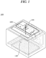
- a microwave oven 1000 according to the related art is disclosed.
- a space 1100 for accommodating food (or cooking ingredients) is provided inside the microwave oven 1000.
- Microwaves emitted from an antenna 1200 is transmitted to the space 1100.
- the microwaves are generated from a power source (not shown) located outside of the microwave oven 1000.
- the generated microwaves are transmitted through an electric wire (not shown) that connects the power source (not shown) and the antenna 1200.
- the antenna 1200 and the electric wire (not shown) are respectively connected to a connector 1300.
- the microwaves transmitted through the electric wire (not shown) may be transferred to the space 1100 through the antenna 1200 and the connector 1300.
- the antenna 1200 and the electric wire (not shown) are coupled to the microwave oven 1000 via the connector 1300.
- the connector 1300 includes a line connecting portion 1320 connected to the electric wire (not shown) and a conductive portion 1330 connected to the antenna 1200.
- the conductive portion 1330 extends by penetrating through an inner space of a body part 1310 and the line connecting portion 1320.
- the conductive portion 1330 is surrounded by an insulating portion 1340 provided in the inner space of the body part 1310.
- the insulating portion 1340 prevents electric connection between the line connecting portion 1320 and the conductive portion 1330. In addition, the insulating portion 1340 supports the conductive portion 1330 so as to retain it securely in a specific (or predetermined) position within the space of the body 1310.
- the related art insulating portion 1340 is made of Teflon, etc.
- the maximum continuous service temperature of Teflon is approximately 250°C. Accordingly, when temperature inside the microwave oven 1000 exceeds 250°C, it may cause thermal damage to the insulating portion 1340.
- insulation reliability between the line connecting portion 1320 and the conductive portion 1330 may be reduced.
- Operational reliability of the entire microwave oven 1000 may also be reduced since the conductive portion 1330 cannot be held securely in its predetermined position.
- microwave transmission efficiency can be decreased, which may be resulted in a decrease in functioning of the microwave oven 1000, namely heating of food.
- a microwave system is disclosed in Korean Laid-Open Patent Application No. KR 10-2020-0021067 , which is hereby incorporated by reference. More specifically, a microwave system that converts microwaves to be transmitted via a coaxial cable using a waveguide-coaxial cable conversion adapter is disclosed.
- a microwave oven and a radiation module thereof discloses a microwave oven and a radiation module thereof.
- a radiation module including a waveguide that provides a horizontal helical traveling path for microwaves and a pair of slot antennas provided on a bottom surface of the waveguide.
- Such a radiation module can radiate microwaves transmitted through the waveguide.
- a method for preventing damage to a connector that connects the waveguide and the pair of slot antennas is not provided. That is, in the related art Patent Document, a radiation method of the transmitted microwaves is only provided, and a structure and a material of the connector through which the microwaves travel are not disclosed.
- the present disclosure is directed to providing a transfer connector capable of solving the aforementioned problems.
- One aspect of the present disclosure is to provide a transfer connector that can be stably operated at a high temperature.
- Another aspect of the present disclosure is to provide a transfer connector capable of preventing damage even used in a high-temperature operating environment.
- Still another aspect of the present disclosure is to provide a transfer connector that can be connected to an external power source in a stable manner.
- Still another aspect of the present disclosure is to provide a transfer connector that can prevent electric connection between each of the components even used in a high-temperature operating environment.
- Still another aspect of the present disclosure is to provide a transfer connector capable of effectively dissipating heat.
- Embodiments disclosed herein provide a transfer connector that may include: a body part extending in one direction and provided therein with a hollow portion; a base coupled to the body part and having a communication hole formed therethrough so as to communicate with the hollow portion; an electric connection part electrically connected to an external power source, penetrating through the hollow portion and the communication hole, and extending in a direction the same as the one direction in which the body part extends; and a dielectric material accommodated in the hollow portion and disposed between an inner circumferential surface of the body part and an outer circumferential surface of the electric connection part.
- the dielectric material may be surrounded by the inner circumferential surface of the body part and surround the outer circumferential surface of the electric connection part.
- the dielectric material may include any one of quartz, silica, mica, and alumina materials.
- the dielectric material and the inner circumferential surface of the body part may be joined together through brazing, and the dielectric material and the outer circumferential surface of the electric connection part may be joined together through brazing, so as to prevent electric connection between the body part and the electric connection part.
- Embodiments disclosed herein also provide a transfer connector that may include: a body part extending in one direction and provided therein with a hollow portion; a base coupled to the body part and having a communication hole formed therethrough so as to communicate with the hollow portion; an electric connection part electrically connected to an external power source, penetrating through the hollow portion and the communication hole, and extending in a direction the same as the one direction in which the body part extends; and a guide part disposed to face the body part with the base interposed therebetween.
- the guide part may include a penetrating portion formed therethrough to communicate with the communication hole, and to which the electric connection part is penetratingly coupled. A surface that surrounds the penetrating portion may be in contact with an outer circumferential surface of the electric connection part.
- the guide part may include any one of quartz, silica, mica and alumina materials.
- a diameter of a cross section of the hollow portion and a diameter of a cross section of the communication hole may be greater than a diameter of a cross section of the electric connection part, and a diameter of the penetrating portion may be less than or equal to the diameter of the cross section of the electric connection part.
- the electric connection part may be spaced apart from an inner circumferential surface of the body part that surrounds the hollow portion and an inner circumferential surface of the base that surrounds the communication hole.
- Embodiments disclosed herein further provide a transfer connector that may include: a body part extending in one direction and provided therein with a hollow portion; a base coupled to the body part and having a communication hole formed therethrough so as to communicate with the hollow portion; an electric connection part electrically connected to an external power source, penetrating through the hollow portion and the communication hole, and extending in a direction the same as the one direction in which the body part extends; a guide part disposed to face the body part with the base interposed therebetween; and a heat dissipation member coupled to an outer circumferential surface of the body part, and extending radially outward with respect to a cross-sectional center of the body part.
- the guide part may be provided in plurality, so that the plurality of guide parts is disposed to be spaced apart from each other along the one direction in which the body part extends.
- the body part may include an engaging protrusion extending radially inward from an inner circumferential surface of the body part toward the cross-sectional center of the body part.
- the base may include a support protrusion extending radially inward from an inner circumferential surface thereof that surrounds the communication hole toward a cross-sectional center thereof. Any one of the plurality of the guide parts may be seated on the engaging protrusion, and a remaining one of the plurality of guide parts may be seated on the support protrusion.
- a diameter of a cross section of the guide part may be greater than or equal to a diameter of a cross section of the hollow portion, and a diameter of a cross section of the communication hole may be less than the diameter of the cross section of the hollow portion.
- the heat dissipation member may be provided in plurality, so that the plurality of heat dissipation members is disposed to be spaced apart from each other in the one direction in which the body part extends.
- Embodiments disclosed herein also provide a transfer connector that may include: a body part extending in one direction and provided therein with a hollow portion; a base coupled to the body part and having a communication hole formed therethrough so as to communicate with the hollow portion; an electric connection part electrically connected to an external power source, penetrating through the hollow portion and the communication hole, and extending in a direction the same as the one direction in which the body part extends; a dielectric material accommodated in the hollow portion and disposed between an inner circumferential surface of the body part and an outer circumferential surface of the electric connection part; and a heat dissipation member coupled to an outer circumferential surface of the body part, and extending radially outward with respect to a cross-sectional center of the body part.
- the dielectric material may be surrounded by the inner circumferential surface of the body part and surround the outer circumferential surface of the electric connection part.
- the dielectric material may include any one of quartz, silica, mica, and alumina materials.
- the heat dissipation member may be provided in plurality, so that the plurality of heat dissipation members is disposed to be spaced apart from each other in the one direction in which the body part extends.
- Embodiments disclosed herein further provide a transfer connector that may include: a body part extending in one direction and provided therein with a hollow portion; a base coupled to the body part and having a communication hole formed therethrough so as to communicate with the hollow portion; an electric connection part electrically connected to an external power source, penetrating through the hollow portion and the communication hole, and extending in a direction the same as the one direction in which the body part extends; a guide part disposed to face the body part with the base interposed therebetween; and a heat dissipation member coupled to an outer circumferential surface of the body part, and extending radially outward with respect to a cross-sectional center of the body part.
- the guide part may include a penetrating portion formed therethrough to communicate with the communication hole, and to which the electric connection part is penetratingly coupled. A surface surrounding the penetrating portion may be in contact with the outer circumferential surface of the electric connection part.
- the guide part may include any one of quartz, silica, mica, and alumina materials.
- a diameter of a cross section of the hollow portion and a diameter of a cross section of the communication hole may be greater than a diameter of a cross section of the electric connection part, and a diameter of the penetrating portion may be less than or equal to the diameter of the cross section of the electric connection part.
- the electric connection part may be spaced apart from an inner circumferential surface of the body part that surrounds the hollow portion and an inner circumferential surface of the base that surrounds the communication hole.
- the heat dissipation member may be provided in plurality, so that the plurality of heat dissipation members is disposed to be spaced apart from each other in the one direction in which the body part extends.
- the embodiments of the present disclosure may provide at least one or more of the following benefits.
- a transfer connector is provided with a dielectric material.
- the dielectric material is made of a material that can prevent damage or deformation by heat at a high temperature of 500°C or higher.
- the dielectric material is made of any one of quartz, silica, mica, and alumina materials.
- the transfer connector can be stably operated in high-temperature operating conditions.
- an electric connection part which is electrically connected to an external power source, is inserted into a body part and a base. That is, the electric connection part is not exposed to the outside. In one embodiment, the electric connection part is surrounded by a dielectric material.
- the electric connection part is not damaged by heat generated when the oven is operated.
- damage to the transfer connector can be prevented even used in a high-temperature operation environment.
- the electric connection part as a constituting component, is integrally formed with the transfer connector.
- the electric connection part is coupled to the body part and the base through the dielectric material.
- the electric connection part is coupled to the body part and the base through a guide part.
- the electric connection part is accommodated in an inner space of the body part and the base while being surrounded (or covered) by the dielectric material.
- the electric connection part is accommodated in the inner space of the body part and the base, and coupled to the guide part to be spaced apart from the body part and the base.
- the dielectric material is made of a heat-proof material that can withstand high temperature.
- air serves as a dielectric material instead of the dielectric material. Accordingly, when the oven is operated, the electric connection part, the body part, and the base can be electrically separated from one another.
- a heat dissipation member is provided on an outer circumference of the body part.
- the heat dissipation member is coupled to or is in contact with the outer circumferential surface of the body part so as to receive heat transferred to the body part. That is, heat generated in the oven is transmitted to the heat dissipation member through the base and the body part.
- the heat dissipation member is provided in a manner of maximizing an area in contact with external air, and the like.
- the heat dissipation member may be provided in plurality to be in contact with the body part.
- heat generated when the oven is operated can be rapidly dissipated. This may prevent the transfer connector from being damaged by the heat generated in the oven, thereby improving operational reliability of the transfer connector.
- an oven refers to an appliance that accommodates food (or cooking ingredients) in a space formed therein to heat and cook the food.
- an oven may be a microwave oven (range), or the like.
- dielectric material used hereinafter refers to an insulator that has polarity in an electric field.
- Transfer connectors 100, 200, 300, 400, and 500 may be provided at the oven.
- the transfer connectors 100, 200, 300, 400, and 500 are provided between an external power source and a cavity which is a space formed inside the oven.
- the transfer connectors 100, 200, 300, 400 and 500 are connected to the external power source by a conductive member (or conducting wire) that serves as a waveguide. Microwaves generated from the external power source may be transmitted into the cavity through the waveguide and the transfer connectors 100, 200, 300, 400, and 500.
- the term "electric connection” used hereinafter means that two or more members are connected in a manner of allowing an electric current or electrical signal to be transmitted.
- the electric connection may be achieved by contact between conductive members, or in a wired manner using a conductive member, or the like. Alternatively, the electric connection may be achieved in a wireless manner.
- front side or part
- rear side or part
- left side or part
- right side or part
- upper side or part
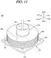
- lower side used hereinafter will be understood with reference to coordinate systems shown in FIGS. 3 , 5 , 8 , 11 and 13 .
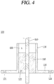
- the transfer connector 100 includes a dielectric material 150 having high thermal resistance. Accordingly, even when temperature inside a cavity of an oven at which the transfer connector 100 is provided rises to a high temperature, damage to the dielectric material 150 may be prevented.
- thermal resistance of the transfer connector 100 may be improved, thereby ensuring insulation between each of the components constituting the transfer connector 100.
- an electric connection part 140 supported by the dielectric material 150 may be held securely in a predetermined position.
- the transfer connector 100 may be integrally formed with a waveguide (not shown). Accordingly, the transfer connector 100 and the waveguide (not shown) are not separated from each other. As a result, an external power source (not shown) and the transfer connector 100 may be securely connected to each other.
- the transfer connector 100 is coupled to an oven (not shown). In one embodiment, the transfer connector 100 may be provided at an upper side of the oven (not shown).
- the transfer connector 100 is connected to the external power source (not shown) through the waveguide (not shown). Microwaves generated from the external power source (not shown) may be transmitted to the transfer connector 100 through the waveguide (not shown).
- the transfer connector 100 is connected to an antenna member (not shown) provided at a cavity of the oven (not shown).
- the microwaves transmitted to the transfer connector 100 may be emitted or radiated into the cavity via the antenna member (not shown).
- the microwaves may be incident on food accommodated in the cavity in various directions. This allows the food to be quickly heated.
- the transfer connector 100 includes a body part 110, a base 120, a hollow portion 130, the electric connection part 140, and the dielectric material 150.
- the body part 110 defines the body of the transfer connector 100.
- the body part 110 extends in one direction, namely a vertical (or up-and-down) direction in the illustrated embodiment.
- the body part 110 has a cylindrical shape with a circular cross section.
- the body part 110 is provided therein with the hollow portion 130 that extends in a direction in which the body part 110 extends, namely the vertical direction in the illustrated embodiment.
- the electric connection part 140 electrically connected to the waveguide (not shown) and the antenna member (not shown) is accommodated in the hollow portion 130.
- An inner circumferential surface of the body part 110 surrounds the hollow portion 130.
- the body part 110 may be formed in a shape that can be supported on the base 120, have a space formed therein, and be connected to the waveguide (not shown).
- the body part 110 is connected to the waveguide (not shown).
- the body part 110 may be integrally formed with the waveguide (not shown). Accordingly, the transfer connector 100 and the waveguide (not shown) may not be separated from each other. As a result, connection reliability between the transfer connector 100 and the waveguide (not shown) may be improved.
- the body part 110 may be made of a conductive material.
- the body part 110 may be made of a material having high rigidity and high thermal resistance. This is to prevent damage from external shock or high heat generated in the oven (not shown).
- the body part 110 may be made of a steel material.
- the base 120 is located beneath the body part 110.
- the body part 110 is supported by the base 120.
- the base 120 supports the body part 110. In addition, the base 120 allows the transfer connector 100 to be coupled to the oven (not shown).
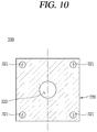
- the base 120 may be provided in the form of a plate. This is to minimize a space occupied by the transfer connector 100 in the oven (not shown). In the illustrated embodiment, the base 120 is formed in a square plate shape.
- the base 120 may be made of a conductive material.
- the base 120 may be made of a material having high rigidity and high thermal resistance. This is to prevent damage from external shock or high heat generated in the oven (not shown).
- the base 120 may be made of a steel material.
- the base 120 is located beneath the body part 110.
- the base 120 may be coupled to a lower end of the body part 110.
- the base 120 may be integrally formed with the body part 110.
- the base 120 includes a fastening member penetrating portion 121 and a communication hole 122.
- the fastening member penetrating portion 121 is formed through the base 120.
- the fastening member penetrating portion 121 penetrates in a thickness direction of the base 120, namely the vertical direction in the illustrated embodiment.
- a fastening member (not shown) that allows the base 120 to be coupled to the oven (not shown) is penetratingly coupled to the fastening member penetrating portion 121.
- the fastening member (not shown) may be configured as a screw or rivet.
- the fastening member penetrating portion 121 is located radially outward of the body part 110. In the illustrated embodiment, the fastening member penetrating portion 121 is located radially outward of the body part 110 to be adjacent to a corner of the base 120.
- the fastening member penetrating portion 121 may be provided in plurality.
- the plurality of fastening member penetrating portions 121 may be spaced apart from each other to be located radially outward of the body part 110.
- four fastening member penetrating portions 121 are provided near the respective corners of the base 120.
- the number and position of the fastening member penetrating portions 121 may vary according to a coupling structure between the transfer connector 100 and the oven (not shown).
- the communication hole 122 is formed through the base 120.
- the communication hole 122 penetrates in a direction toward the body part 110 and a direction opposite to the body part 110, namely the vertical direction in the illustrated embodiment.
- the communication hole 122 communicates with the hollow portion 130 formed inside the body part 110.
- the communication hole 122 may be aligned with the hollow portion 130.
- the communication hole 122 may have a circular cross section corresponding to the hollow portion 130.
- the electric connection part 140 which is inserted into the hollow portion 130, penetrates through the hollow portion 130 and the communication hole 122 so as to be connected to the antenna member (not shown) provided in the oven (not shown). Accordingly, microwaves transmitted to the electric connection part 140 through the waveguide (not shown) may be transferred to the antenna member (not shown).
- the hollow portion 130 is a space to which the electric connection part 140 is penetratingly coupled.
- the hollow portion 130 may be partially filled with the dielectric material 150.
- the hollow portion 130 is provided inside the body part 110.
- the hollow portion 130 is formed through the body part 110.
- the hollow portion 130 may be defined as a space surrounded by the inner circumferential surface of the body part 110.
- the hollow portion 130 extends in a direction in which the body part 110 extends, namely the vertical direction in the illustrated direction.
- An upper side of the hollow portion 130 may be formed through an upper surface of the body part 110.
- a lower side of the hollow portion 130 may communicate with the communication hole 122 of the base 120.
- the hollow portion 130 may have a shape that allows the electric connection part 140 to be penetratingly coupled thereto and the dielectric material 150 to be partially filled therein.
- the hollow portion 130 has a circular cross section and is formed in a cylindrical shape extending in the vertical direction.
- the electric connection part 140 is electrically connected to the external power source (not shown) and the antenna member (not shown) provided in the oven (not shown). That is, the electric connection part 140 provides electric connection between the external power source (not shown) and the antenna member (not shown). Accordingly, the electric connection part 140 may transmit microwaves generated from the external power source (not shown) to the antenna member (not shown).
- the electric connection part 140 is coupled to the hollow portion 130 and the communication hole 122 in a penetrating manner.
- the electric connection part 140 extends to a lower side of the base 120 through the communication hole 122 by passing through an upper opening of the hollow portion 130.
- An end of the electric connection part 140 exposed to an outside of the base 120, namely a lower end of the electric connection part 140 in the illustrated embodiment is coupled to the antenna member (not shown). Accordingly, the electric connection part 140 and the antenna member (not shown) are electrically connected to each other.
- the electric connection part 140 may extend from the waveguide (not shown). That is, unlike the illustrated embodiment in which the electric connection part 140 is provided separately so as to be connected to the waveguide (not shown), the electric connection part 140 may extend directly from the waveguide (not shown) in the embodiment.
- the electric connection part 140 may be made of a conductive material. This is to allow microwaves smoothly move (or travel) between the external power source (not shown), the waveguide (not shown), and the antenna member (not shown). In one embodiment, the electric connection part 140 may be made of a copper or brass material.
- the electric connection part 140 has a circular cross section and extends in a direction in which the body part 110 extends, namely the vertical direction.
- a diameter of the cross section of the electric connection part 140 may be less (or smaller) than that of the hollow portion 130 and the communication hole 122.
- an outer circumferential surface of the electric connection part 140, the inner circumferential surface of the body part 110, and an inner circumferential surface of the base 120 are spaced apart from one another.
- the dielectric material 150 is partially filled in a space generated therebetween.
- the electric connection part 140 is supported by the dielectric material 150. That is, the outer circumferential surface of the electric connection part 140 penetratingly coupled to the hollow portion 130 and the communication hole 122 is surrounded by the dielectric material 150.
- the electric connection part 140 is penetratingly coupled to the hollow portion 130 and the communication hole 122, it is not shaken or moved, thereby ensuring operational reliability of the transfer connector 100.
- the dielectric material 150 prevents electric connection between the body part 110 and the electric connection part 140.
- the dielectric material 150 supports the electric connection part 140 that is inserted into the hollow portion 130 and the communication hole 122.
- the dielectric material 150 may be made of an insulating material. This is to prevent electric connection between the body part 110 and the electric connection part 140.
- the dielectric material 150 may be made of a material that can minimize damage or deformation caused by heat in a high temperature environment. This is to prevent the dielectric material 150 from being damaged by heat. As the microwave oven is operated, the temperature inside the cavity increases and heat is generated accordingly.
- the high temperature may be 500°C or higher.
- the dielectric material 150 may be made of at least one of quartz, silica, mica, and alumina materials.
- the dielectric material 150 is disposed at the hollow portion 130 and the communication hole 122.
- the dielectric material 150 extends from one point of the hollow portion 130 to the communication hole 122.
- the dielectric material 150 extends from a height of 2/3 of the hollow portion 130 to the communication hole 122.
- the dielectric material 150 is located radially outward of the electric connection part 140.
- the dielectric material 150 surrounds the outer circumferential surface of the electric connection part 140.
- the dielectric material 150 is coupled to the outer circumferential surface of the electric connection part 140, so as to surround the electric connection part 140.
- the dielectric material 150 may be coupled to the outer circumferential surface of the electric connection part 140.
- the dielectric material 150 is located radially inward of the inner circumferential surface of the body part 110 and an inner circumneutral surface of the communication hole 122. Each of the inner circumferential surfaces of the body part 110 and the communication hole 122 surrounds the dielectric material 150. The dielectric material 150 may be coupled to each of the inner circumferential surfaces of the body part 110 and the communication hole 122.
- the inner circumferential surfaces of the body part 110 and the communication hole 122 are located radially outward of the dielectric material 150.
- the electric connection part 140 is located radially inward of the dielectric material 150.
- the dielectric material 150 is coupled to each of the inner circumferential surfaces of the body part 110 and the base 120. Accordingly, the dielectric material 150 is not moved inside the hollow portion 130 and the communication hole 122.
- the dielectric material 150 and each of the inner circumferential surfaces of the body part 110 and the base 120 are joined together through brazing using a metal or ceramic material.
- the dielectric material 150 is coupled to the outer circumferential surface of the electric connection part 140. Accordingly, the electric connection part 140 is not moved inside the hollow portion 130 and the communication hole 122.
- the dielectric material 150 and the outer circumferential surface of the electric connection part 140 may be joined together through brazing using a metal or ceramic material.
- the dielectric material 150 with high thermal resistance is provided.
- the dielectric material 150 is filled in the hollow portion 130 and the communication hole 122.
- the dielectric material 150 is coupled to the inner circumferential surface of the body part 110 that surrounds the hollow portion 130 and the inner circumferential surface of the base 120 that surrounds the communication hole 122.
- the electric connection part 140 is accommodated in the dielectric material 150.
- the dielectric material 150 is coupled to the outer circumferential surface of the electric connection part 140.
- the oven equipped with the transfer connector 100 is operated at a high temperature of 250°C or higher, damage to the dielectric material 150 may be prevented. This may allow the dielectric material 150, the body part 110, the base 120, and the electric connection part 140 to be securely coupled to one another.
- a dielectric material is not provided, and instead air is utilized as the dielectric material. Accordingly, even when temperature inside a cavity of an oven at which the transfer connector 200 is provided rises to a high temperature, structural deformation of the transfer connector 200 may be minimized.
- thermal resistance of the transfer connector 200 may be improved, thereby ensuring insulation between each of the components constituting the transfer connector 200.
- an electric connection part 240 supported by a guide part (bottom plate) 250 may be held securely in a predetermined position.
- the transfer connector 200 may be integrally formed with a waveguide (not shown). Accordingly, the transfer connector 200 and the waveguide (not shown) are not separated from each other. As a result, an external power source (not shown) and the transfer connector 200 may be securely connected to each other.
- the transfer connector 200 is coupled to an oven (not shown). In one embodiment, the transfer connector 200 may be provided at an upper side of the oven (not shown).
- the transfer connector 200 is connected to the external power source (not shown) through the waveguide (not shown). Microwaves generated from the external power source (not shown) may be transmitted to the transfer connector 200 through the waveguide (not shown).
- the transfer connector 200 is connected to an antenna member (not shown) provided at a cavity of the oven (not shown).
- the microwaves transmitted to the transfer connector 200 may be emitted or radiated into the cavity via the antenna member (not shown).
- the microwaves may be incident on food accommodated in the cavity in various directions. This allows the food to be quickly heated.
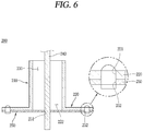
- the transfer connector 200 includes a body part 210, a base 220, a hollow portion 230, the electric connection part 240, and the guide part 250.
- the body part 210 defines the body of the transfer connector 200.
- the body part 210 extends in one direction, namely a vertical (or up-and-down) direction in the illustrated embodiment.
- the body part 210 has a cylindrical shape with a circular cross section.
- the hollow portion 230 is provided therein with the hollow portion 230 that extends in a direction in which the body part 210 extends, namely the vertical direction in the illustrated embodiment.
- the electric connection part 240 electrically connected to the waveguide (not shown) and the antenna member (not shown) is accommodated in the hollow portion 230.
- An inner circumferential surface of the body part 210 surrounds the hollow portion 230.
- the body part 210 may be formed in a shape that can be supported on the base 220, have a space formed therein, and be connected to the waveguide (not shown).
- the body part 210 is connected to the waveguide (not shown).
- the body part 210 may be integrally formed with the waveguide (not shown). Accordingly, the transfer connector 200 and the waveguide (not shown) may not be separated from each other. As a result, connection reliability between the transfer connector 200 and the waveguide (not shown) may be improved.
- the body part 210 may be made of a conductive material.
- the body part 210 may be made of a material having high rigidity and high thermal resistance. This is to prevent damage from external shock or high heat generated in the oven (not shown).
- the body part 210 may be made of a steel material.
- the base 220 is located beneath the body part 210.
- the body part 210 is supported by the base 220.
- the base 220 supports the body part 210. In addition, the base 220 allows the transfer connector 200 to be coupled to the oven (not shown).
- the base 220 may be provided in the form of a plate. This is to minimize a space occupied by the transfer connector 200 in the oven (not shown). In the illustrated embodiment, the base 220 is formed in a square plate shape.
- the base 220 may be made of a conductive material.
- the base 220 may be made of a material having high rigidity and high thermal resistance. This is to prevent damage from external shock or high heat generated in the oven (not shown).
- the base 220 may be made of a steel material.
- the base 220 is located beneath the body part 210.
- the base 220 may be coupled to a lower end of the body part 210.
- the base 220 may be integrally formed with the body part 210.
- the base 220 includes a fastening member penetrating portion 221 and a communication hole 222.
- the fastening member penetrating portion 221 is formed through the base 220.
- the fastening member penetrating portion 221 penetrates in a thickness direction of the base 220, namely the vertical direction in the illustrated embodiment.
- a fastening member (not shown) that allows the base 220 to be coupled to the oven (not shown) is penetratingly coupled to the fastening member penetrating portion 221.
- the fastening member (not shown) may be configured as a screw or rivet.
- the fastening member penetrating portion 221 is located radially outward of the body part 210. In the illustrated embodiment, the fastening member penetrating portion 221 is located radially outward of the body part 210 to be adjacent to a corner of the base 220.
- the fastening member penetrating portion 221 may be provided in plurality.
- the plurality of fastening member penetrating portions 221 may be spaced apart from each other to be located radially outward of the body part 210.
- four fastening member penetrating portions 221 are provided near the respective corners of the base 220.
- the number and position of the fastening member penetrating portions 221 may vary according to a coupling structure between the transfer connector 200 and the oven (not shown).
- the communication hole 222 is formed through the base 220.
- the communication hole 222 penetrates in a direction toward the body part 210 and a direction opposite to the body part 210, namely the vertical direction in the illustrated embodiment.
- the communication hole 222 communicates with the hollow portion 230 formed inside the body part 210.
- the communication hole 222 may be aligned with the hollow portion 230.
- the communication hole 222 may have a circular cross section corresponding to the hollow portion 230.
- the electric connection part 240 which is inserted into the hollow portion 230, penetrates through the hollow portion 230 and the communication hole 222 to be connected to the antenna member (not shown) provided in the oven (not shown). Accordingly, microwaves transmitted to the electric connection part 240 through the waveguide (not shown) may be transferred to the antenna member (not shown).
- the hollow portion 230 is a space to which the electric connection part 240 is penetratingly coupled.
- the hollow portion 230 is provided inside the body part 210.
- the hollow portion 230 is formed through the body part 210.
- the hollow portion 230 may be defined as a space surrounded by the inner circumferential surface of the body part 210.
- the hollow portion 230 extends in a direction in which the body part 210 extends, namely the vertical direction in the illustrated embodiment.
- An upper side of the hollow portion 230 may be formed through an upper surface of the body part 210.
- a lower side of the hollow portion 230 may communicate with the communication hole 222 of the base 220.
- the hollow portion 230 may have a shape that allows the electric connection part 240 to be penetratingly coupled thereto.
- the hollow portion 230 has a circular cross section and is formed in a cylindrical shape extending in the vertical direction.
- the hollow portion 230 communicates with the communication hole 222.
- the electric connection part 240 inserted into the hollow portion 230 may extend to the communication hole 222.
- the hollow portion 230 is empty except an area (or portion) in which the electric connection part 240 is accommodated. That is, air is received in the remaining area.
- the air accommodated in the hollow portion 230 serves as a dielectric material that provides insulation between the electric connection part 240 and the body part 210.
- the electric connection part 240 is electrically connected to the external power source (not shown) and the antenna member (not shown) provided in the oven (not shown). That is, the electric connection part 240 provides electric connection between the external power source (not shown) and the antenna member (not shown). Accordingly, the electric connection part 240 may transmit microwaves generated from the external power source (not shown) to the antenna member (not shown).
- the electric connection part 240 is coupled to the hollow portion 230 and the communication hole 222 in a penetrating manner.
- the electric connection part 240 extends to a lower side of the base 220 through the communication hole 222 by passing through an upper opening of the hollow portion 230.
- An end of the electric connection part 240 exposed to an outside of the base 220, namely a lower end of the electric connection part 240 in the illustrated embodiment is coupled to the antenna member (not shown). Accordingly, the electric connection part 240 and the antenna member (not shown) are electrically connected to each other.
- the electric connection part 240 may extend from the waveguide (not shown). That is, unlike the illustrated embodiment in which the electric connection part 240 is provided separately so as to be connected to the waveguide (not shown), the electric connection part 240 may extend directly from the waveguide (not shown) in the embodiment.
- the electric connection part 240 may be made of a conductive material. This is to allow microwaves to smoothly travel or move between the external power source (not shown), the waveguide (not shown), and the antenna member (not shown). In one embodiment, the electric connection part 240 may be made of a copper or brass material.
- the electric connection part 240 has a circular cross section and extends in a direction in which the body part 210 extends, namely the vertical direction.
- a diameter of the cross section of the electric connection part 240 may be less than a diameter of a cross section of the hollow portion 230. Accordingly, an outer circumferential surface of the electric connection part 240 and the inner circumferential surface of the body part 210 are spaced apart from each other.
- the diameter of the cross section of the electric connection part 240 may be less than a diameter of a cross section of the communication hole 222 of the base 220. Accordingly, the outer circumferential surface of the electric connection part 240 and an inner circumferential surface of the base 220 are also spaced apart from each other.
- the diameter of the cross section of the electric connection part 240 may be equal to a diameter of a cross section of a first penetrating portion 251 of the guide part 250. Accordingly, the outer circumferential surface of the electric connection part 240 and an inner circumferential surface of the guide part 250 are in contact with each other.
- the electric connection part 240 is supported by the guide part 250. That is, the outer circumferential surface of the electric connection part 240 that is penetratingly coupled to the hollow portion 230 and the communication hole 222 is brought into contact with the inner circumferential surface of the guide part 250 that surrounds the first penetrating portion 251 provided at the guide part 250.
- the outer circumferential surface of the electric connection part 240 may be coupled to the inner circumferential surface of the guide part 250.
- the outer circumferential surface of the electric connection part 240 and the inner circumferential surface of the guide part 250 may be joined together through brazing using a metal or ceramic material.
- the electric connection part 240 is penetratingly coupled to the hollow portion 230 and the communication hole 222, it is not shaken or moved, thereby ensuring operational reliability of the transfer connector 200.
- the guide part 250 supports the base 220. In addition, the guide part 250 supports the electric connection part 240 penetratingly coupled to the hollow portion 230 and the communication hole 222.
- the guide part 250 may be made of an insulating material. This is to prevent electric connection between the body part 210 and the electric connection part 240.
- the guide part 250 may be made of a material that can minimize damage or deformation caused by heat in a high-temperature environment. This is to prevent the guide part 250 from being damaged by heat. As the microwave oven is operated, the temperature inside the cavity increases and heat is generated accordingly. For example, the high temperature may be 500°C or higher.
- the guide part 250 may, preferably, be made of a material that allows microwaves to pass therethrough and prevents electric connection.
- the guide part 250 may be made of at least one of quartz, silica, mica, and alumina materials.
- the guide part 250 supports the base 220. In the illustrated embodiment, the guide part 250 is located beneath the base 220. The guide part 250 is coupled to a lower surface of the base 220.
- the guide part 250 may have a shape suitable for being coupled to the base 220.
- the guide part 250 is formed in a square plate shape corresponding to the base 220.
- the shape of the guide part 250 may vary according to the shape of base 220.
- the guide part 250 is coupled to the base 220.
- surfaces that the guide part 250 and the base 220 face each other may be coupled to be in close contact with each other.
- the surfaces that the guide part 250 and the base 220 face each other may be joined together through brazing using a metal or ceramic material.
- the guide part 250 includes the first penetrating portion 251 and a second penetrating portion 252.
- the first penetrating portion 251 is a space to which the electric connection part 240 is penetratingly coupled.
- the first penetrating portion 251 is formed through the guide part 250.
- the electric connection part 240 penetratingly coupled to the hollow portion 230 may extend to the first penetrating portion 251 in a penetrating manner, so as to be coupled to the antenna member (not shown).
- the first penetrating portion 251 communicates with the communication hole 222 and the hollow portion 230.
- the electric connection part 240 inserted into the hollow portion 230 may be inserted into the communication hole 222 and the first penetrating portion 251.
- the first penetrating portion 251 extends in a direction in which the body part 210 extends, namely the vertical direction in the illustrated embodiment.
- the first penetrating portion 251 communicates with the hollow portion 230.
- the electric connection part 240 penetratingly coupled to the hollow portion 230 may extend to the first penetrating portion 251.
- the first penetrating portion 251 is disposed to overlap the hollow portion 230. In one embodiment, the first penetrating portion 251 may be disposed to have the same central axis as the hollow portion 230.
- the first penetrating portion 251 has a circular cross section.
- a diameter of the first penetrating portion 251 may be less than or equal to a diameter of the electric connection part 240.
- the electric connection part 240 may be fitted to the first penetrating portion 251.
- a surface that surrounds the first penetrating portion 251, namely the inner circumferential surface of the guide part 250 may be coupled to the outer circumferential surface of the electric connection part 240.
- the inner circumferential surface of the guide part 250 and the outer circumferential surface of the electric connection part 240 may be joined together through brazing using a metal or ceramic material.
- the second penetrating portion 252 is a space to which the fastening member (not shown) that allows the guide part 250 and the base 220 to be coupled to each other is penetratingly coupled.
- the fastening member (not shown) may be penetratingly coupled to the second penetrating portion 252 and the fastening member penetrating portion 221.
- the second penetrating portion 252 communicates with the fastening member penetrating portion 221.
- the second penetrating portion 252 is formed through the guide part 250.
- the second penetrating portion 252 is located radially outward of the first penetrating portion 251.
- the second penetrating portion 252 may be provided in plurality.
- the plurality of second penetrating portions 252 may be spaced apart from one another.
- four second penetrating portions 252 are disposed to be adjacent to the respective corners of the guide part 250.
- the second penetrating portion 252 may overlap the fastening member penetrating portion 221.
- the second penetrating portion 252 may be disposed to have the same central axis as the fastening member penetrating portion 221.
- the second penetrating portion 252 may have a diameter of its cross section equal to a diameter of a cross section of the fastening member penetrating portion 221, and have a circular shape with the same central axis as the fastening member penetrating portion 221.
- a dielectric material that provides insulation between the body part 210 and the electric connection part 240 is not required.
- the electric connection part 240 is accommodated in the hollow portion 230 formed inside the body part 210.
- the electric connection part 240 is spaced apart from the inner circumferential surface of the body part 210, namely a surface that surrounds the hollow portion 230.
- the electric connection part 240 and the body part 210 are not electrically connected to each other.
- a lower side of the electric connection part 240 is supported by the guide part 250. That is, the lower side of the electric connection part 240 is inserted into the first penetrating portion 251 formed through the guide part 250.
- the diameter of the first penetrating portion 251 is less than or equal to the diameter of the cross section of the electric connection part 240, thereby preventing the inserted electric connection part 240 from being shaken or moved.
- the dielectric material which may be damaged by the high temperature, is not provided in the transfer connector 200 according to this embodiment.
- the body part 210, the base 220, and the electric connection part 240 may be securely coupled to one another.
- a dielectric material is not provided, and instead air is used as the dielectric material. Accordingly, even when temperature inside a cavity of an oven at which the transfer connector 300 is provided rises to a high temperature, structural deformation of the transfer connector 300 may be minimized.
- thermal resistance of the transfer connector 300 may be improved, thereby ensuring insulation between each of the components constituting the transfer connector 300.
- an electric connection part 340 supported by a guide part 350 may be held securely in a predetermined position.
- a heat dissipation member 360 for dissipating heat generated in the oven (not shown) is provided. Accordingly, heat generated when the oven (not shown) is operated may be quickly and effectively dissipated.
- the transfer connector 300 may be integrally formed with a waveguide (not shown). Accordingly, the transfer connector 300 and the waveguide (not shown) are not separated from each other. As a result, an external power source (not shown) and the transfer connector 300 may be securely connected to each other.
- the transfer connector 300 is coupled to the oven (not shown). In one embodiment, the transfer connector 300 may be provided at an upper side of the oven (not shown).
- the transfer connector 300 is connected to the external power source (not shown) through the waveguide (not shown). Microwaves generated from the external power source (not shown) may be transmitted to the transfer connector 300 through the waveguide (not shown).
- the transfer connector 300 is connected to an antenna member (not shown) provided at a cavity of the oven (not shown).
- the microwaves transmitted to the transfer connector 300 may be emitted or radiated into the cavity via the antenna member (not shown).
- the microwaves may be incident on food accommodated in the cavity in various directions. This allows the food to be quickly heated.
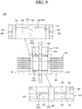
- the transfer connector 300 includes a body part 310, a base 320, a hollow portion 330, the electric connection part 340, the guide part 350, and the heat dissipation member 360.
- the body part 310 defines the body of the transfer connector 300.
- the body part 310 extends in one direction, namely a vertical (or up-and-down) direction in the illustrated embodiment.
- the body part 310 has a cylindrical shape with a circular cross section.
- the hollow portion 330 is provided therein with the body part 310 that extends in a direction in which the body part 310 extends, namely the vertical direction in the illustrated embodiment.
- the electric connection part 340 electrically connected to the waveguide (not shown) and the antenna member (not shown) is accommodated in the hollow portion 330.
- An inner circumferential surface of the body part 310 surrounds the hollow portion 330.
- the body part 310 may be formed in a shape that can be supported on the base 320, have a space formed therein, and be connected to the waveguide (not shown).
- the body part 310 includes an engaging protrusion 311.
- the engaging protrusion 311 supports the guide part 350 disposed at the hollow portion 330 formed inside the body part 310.
- the engaging protrusion 311 is located at the inner circumferential surface of the body part 310, namely a surface that surrounds the hollow part 330.
- the engaging protrusion 311 protrudes radially inward from the inner circumferential surface of the body part 310.
- the engaging protrusion 311 extends from the inner circumferential surface of the body part 310 toward a horizontal center of the body part 310.
- the engaging protrusion 311 may be formed in a ring shape. That is, the engaging protrusion 311 may extend at a specific height along the inner circumferential surface of the body part 310.
- the engaging protrusion 311 supports a first guide portion 351 located thereon. Accordingly, the guide part 350 provided at the hollow portion 330 may be maintained in its original (or predetermined) position without being moved downward by the engaging protrusion 311.
- the engaging protrusion 311 is located above a support (or supporting) protrusion 323 of the base 320 to be spaced apart from the support protrusion 323. A space is generated between the engaging protrusion 311 and the support protrusion 323. Air is accommodated in the space, so as to serve as a dielectric material.
- the number and position of the engaging protrusions 311 may vary according to the number and position of the guide parts 350.
- the body part 310 is connected to the waveguide (not shown).
- the body part 310 may be integrally formed with the waveguide (not shown). Accordingly, the transfer connector 300 and the waveguide (not shown) may not be separated from each other. As a result, connection reliability between the transfer connector 300 and the waveguide (not shown) may be improved.
- the body part 310 may be made of a conductive material.
- the body part 310 may be made of a material having high rigidity and high thermal resistance. This is to prevent damage from external shock or high heat generated in the oven (not shown).
- the body part 310 may be made of a steel material.
- the base 320 is located beneath the body part 210.
- the body part 310 is supported by the base 320.
- the base 320 supports the body part 310. In addition, the base 320 allows the transfer connector 300 to be coupled to the oven (not shown).
- the base 320 may be provided in the form of a plate. This is to minimize a space occupied by the transfer connector 300 in the oven (not shown). In the illustrated embodiment, the base 320 is formed in a square plate shape.
- the base 320 may be made of a conductive material.
- the base 320 may be made of a material having high rigidity and high thermal resistance. This is to prevent damage from external shock or high heat generated in the oven (not shown).
- the base 320 may be made of a steel material.
- the base 320 is located beneath the body part 310.
- the base 320 may be coupled to a lower end of the body part 310.
- the base 320 may be integrally formed with the body part 310.
- the base 320 includes a fastening member penetrating portion 321, a communication hole 322, and the support protrusion 323.
- the fastening member penetrating portion 321 is formed through the base 320.
- the fastening member penetrating portion 321 penetrates in a thickness direction of the base 320, namely the vertical direction in the illustrated embodiment.
- a fastening member (not shown) that allows the base 320 to be coupled to the oven (not shown) is penetratingly coupled to the fastening member penetrating portion 321.
- the fastening member (not shown) may be implemented as a screw or rivet.
- the fastening member penetrating portion 321 is located radially outward of the body part 310. In the illustrated embodiment, the fastening member penetrating portion 321 is located radially outward of the body part 310 to be adjacent to a corner of the base 320.
- the fastening member penetrating portion 321 may be provided in plurality.
- the plurality of fastening member penetrating portions 321 may be spaced apart from each other to be located radially outward of the body part 310.
- four fastening member penetrating portions 321 are provided near the respective corners of the base 320.
- the number and position of the fastening member penetrating portions 321 may vary according to a coupling structure between the transfer connector 300 and the oven (not shown).
- the communication hole 322 is formed through the base 320.
- the communication hole 322 penetrates in a direction toward the body part 310 and a direction opposite to the body part 310, namely the vertical direction in the illustrated embodiment.
- the communication hole 322 communicates with the hollow portion 330 formed inside the body part 310.
- the communication hole 322 may be aligned with the hollow portion 330.
- the communication hole 322 may have a circular cross section corresponding to the hollow portion 330.
- the electric connection part 340 which is inserted into the hollow portion 330, penetrates through the hollow portion 330 and the communication hole 322 to be connected to the antenna member (not shown) provided in the oven (not shown). Accordingly, microwaves transmitted to the electric connection part 340 through the waveguide (not shown) may be transferred to the antenna member (not shown).
- the support protrusion 323 supports a second guide portion 352 located thereon. Accordingly, the guide part 350 provided at the hollow portion 330 may be maintained in its original (or predetermined) position without being moved downward by the support protrusion 323.
- the support protrusion 323 protrudes radially inward from an inner circumferential surface of the base 320. That is, the support protrusion 323 may be defined as a protrusion including a surface that surrounds the communication hole 322.
- a horizontal cross section of the base 320 is formed such that a diameter of the communication hole 322 provided therein is less than a diameter of the hollow portion 330.
- the guide part 350 may have a diameter greater than or equal to the diameter of the hollow portion 330. Accordingly, the guide part 350 may be supported by the support protrusion 323.
- the support protrusion 323 is located below the engaging protrusion 311 to be spaced apart from the engaging protrusion 311. Air is accommodated in a space formed between the support protrusion 323 and the engaging protrusion 311. Air may serve as a dielectric material.
- the hollow portion 330 is a space to which the electric connection part 340 is penetratingly coupled.
- the hollow portion 330 is provided inside the body part 310.
- the hollow portion 330 is formed through the body part 310.
- the hollow portion 330 may be defined as a space surrounded by the inner circumferential surface of the body part 310.
- the hollow portion 330 extends in a direction in which the body part 310 extends, namely the vertical direction in the illustrated embodiment.
- An upper side of the hollow portion 330 may be formed through an upper surface of the body part 310.
- a lower side of the hollow portion 330 may communicate with the communication hole 322 of the base 320.
- the guide part 350 is disposed at the hollow portion 330.
- the guide part 350 is supported by the engaging protrusion 311 protruding from the inner circumferential surface of the body part 310 that surrounds the hollow portion 330.
- the hollow portion 330 may have a shape that allows the electric connection part 340 to be penetratingly coupled thereto.
- the hollow portion 330 has a circular cross section and is formed in a cylindrical shape extending in the vertical direction.
- the hollow portion 330 communicates with the communication hole 522.
- the electric connection part 340 inserted into the hollow portion 330 may extend to the communication hole 322.
- the hollow portion 330 is empty except areas (or portions) in which the electric connection part 340 is accommodated and the guide part 350 is disposed. That is, air is received in the remaining area.
- the air accommodated in the hollow portion 330 serves as a dielectric material that provides insulation between the electric connection part 340 and the body part 310.
- the electric connection part 340 is electrically connected to the external power source (not shown) and the antenna member (not shown) provided in the oven (not shown). That is, the electric connection part 340 provides electric connection between the external power supply source (not shown) and the antenna member (not shown). Accordingly, the electric connection part 340 may transmit microwaves generated from the external power source (not shown) to the antenna member (not shown).
- the electric connection part 340 is coupled to the hollow portion 330 and the communication hole 322 in a penetrating manner.
- the electric connection part 340 extends to a lower side of the base 320 through the communication hole 322 by passing through an upper opening of the hollow portion 330.
- An end of the electric connection part 340 exposed to an outside of the base 320, namely a lower end of the electric connection part 340 in the illustrated embodiment is coupled to the antenna member (not shown). Accordingly, the electric connection part 340 and the antenna member (not shown) are electrically connected to each other.
- the electric connection part 340 may extend from the waveguide (not shown). That is, unlike the illustrated embodiment in which the electric connection part 340 is provided separately so as to be connected to the waveguide (not shown), the electric connection part 340 may extend directly from the waveguide (not shown) in the embodiment.
- the electric connection part 340 may be made of a conductive material. This is to allow microwaves to smoothly travel or move between the external power outlet (not shown), the waveguide (not shown), and the antenna member (not shown). In one embodiment, the electric connection part 340 may be made of a copper or brass material.
- the electric connection part 340 has a circular cross section and extends in a direction in which the body part 310 extends, namely the vertical direction.
- a diameter of the cross section of the electric connection part 340 may be less than a diameter of a cross section of the hollow portion 330. Accordingly, an outer circumferential surface of the electric connection part 340 and the inner circumferential surface of the body part 310 are spaced apart from each other.
- the diameter of the cross section of the electric connection part 340 may be less than a diameter of a cross section of the communication hole 322 of the base 320. Accordingly, the outer circumferential surface of the electric connection part 340 and the inner circumferential surface of the base 320 are spaced apart from each other.
- the diameter of the cross section of the electric connection part 340 may be less than or equal to an inner diameter of the guide part 350. Accordingly, the outer circumferential surface of the electric connection part 340 and an inner circumferential surface of the guide part 350 are in contact with each other.
- the electric connection part 340 is supported by the guide part 350. That is, the outer circumferential surface of the electric connection part 340 that is penetratingly coupled to the hollow portion 330 and the communication hole 322 is brought into contact with inner circumferential surfaces of the guide portions 351 and 352 that surround penetrating portions 351a and 352a.
- the outer circumferential surface of the electric connection part 340 may be coupled to the inner circumferential surface of the guide part 350.
- the outer circumferential surface of the electric connection part 340 and the inner circumferential surface of the guide part 350 may be joined together through brazing using a metal or ceramic material.
- the electric connection part is coupled to the hollow portion 330 and the communicating hole 322, it is not shaken or moved, thereby ensuring operational reliability of the transfer connector 300.
- the guide part 350 supports the electric connection part 340 penetratingly coupled to the hollow portion 330 and the communication hole 322.
- the guide part 350 may be made of an insulating material. This is to prevent electric connection between the body part 310 and the electric connection part 340.
- the guide part 350 may be made of a material that can minimize damage or deformation caused by heat even in a high temperature environment. This is to prevent the guide part 350 from being damaged by heat. As the microwave oven is operated, the temperature inside the cavity increases and heat is generated accordingly.
- the high temperature may be 500°C or higher.
- the guide part 350 may, preferably, be made of a material that allows microwaves to pass therethrough and prevents electric connection.
- the guide part 350 may be made of at least one of quartz, silica, mica, and alumina materials.
- the guide part 350 is provided inside the body part 310.
- the guide part 350 is located in the hollow portion 330 which is a space formed inside the body part 310.
- the guide part 350 is seated or placed on the engaging protrusion 311 formed on the inner circumferential surface of the body part 310 in a protruding manner and the support protrusion 323 of the base 320.
- the guide part 350 is supported by the engaging protrusion 311 and the support protrusion 323.
- the guide part 350 is formed in a ring shape having the penetrating portions 351a and 352a formed therethrough.
- the guide part 350 is formed in a plate shape having the penetrating portions 351 a and 352a formed therein.
- the guide part 350 may have a shape suitable for supporting the electric connection part 340.
- the guide part 350 may be provided in plurality.
- the plurality of guide parts 350 may be spaced apart from each other.
- the guide part 350 includes the first guide portion 351 disposed at an upper position and the second guide portion 352 disposed at a lower position.
- a space formed between the first guide portion 351 and the second guide portion 352 is hollow. That is, air is accommodated between the first guide portion 351 and the second guide portion 352, and thus a dielectric material is not provided (or required).
- the electric connection part 340 is penetratingly coupled to the first guide portion 351 and the second guide portion 352. Accordingly, the electric connection part 340 may not be brought into contact with the body part 310 or the base 320, which provides physical and electrical separation from the body part 310 or the base 320.
- the first guide portion 351 is disposed in the hollow portion 330.
- the first guide portion 351 is located above the second guide portion 352.
- the first guide portion 351 is supported by the engaging protrusion 311.
- An outer diameter of the first guide portion 351 may be greater than or equal to the diameter of the hollow portion 330. Accordingly, the outer diameter of the first guide portion 351 is greater than a diameter of a space surrounded by the engaging protrusion 311. This may allow the first guide portion 351 to be securely seated on the engaging protrusion 311.
- the first guide portion 351 may be fitted to the body part 310.
- the first guide portion 351 includes the first penetrating portion 351a.
- the first penetrating portion 351a is formed through the first guide portion 351.
- the first penetrating portion 351a is formed through first guide portion 351 in a direction in which the body part 310 extends, namely the vertical direction in the illustrated embodiment.
- a cross section of the first penetrating portion 351 a may have a shape corresponding to a shape of the electric connection part 340.
- the electric connection part 340 has the circular cross section, and thus the cross section of the first penetrating portion 351a may be formed in a circular shape.
- a diameter of the cross section of the first penetrating portion 351a namely an inner diameter of the first guide portion 351 may be less than or equal to the diameter of the cross section of the electric connection part 340.
- the electric connection part 340 may be fitted to the first penetrating portion 351a.
- the second guide portion 352 is located in the hollow portion 330.
- the second guide portion 352 is located below the first guide portion 351.
- the second guide portion 352 is supported by the support protrusion 323.
- An outer diameter of the second guide portion 352 may be greater than or equal to the diameter of the hollow portion 330.
- the outer diameter of the second guide portion 352 may be greater than or equal to the diameter of the communication hole 322. Accordingly, the second guide portion 352 may be securely placed on the support protrusion 323.
- the second guide portion 352 may be fitted to the body part 310.
- the second guide portion 352 includes the second penetrating portion 352a.
- the second penetrating portion 352a is formed through the second guide portion 352.
- the second penetrating portion 352a is formed through the second guide portion 352 in a direction in which the body part 310 extends, namely the vertical direction in the illustrated embodiment.
- a cross section of the second penetrating portion 352a may have a shape corresponding to the shape of the electric connection part 340.
- the electric connection part 340 has the circular cross section, and thus, the cross section of the second penetrating portion 352a may be formed in a circular shape.
- a diameter of the cross section of the second penetrating portion 352a namely an inner diameter of the second guide portion 352 may be less than or equal to the diameter of the cross section of the electric connection part 340.
- the electric connection part 340 may be fitted to the second penetrating portion 352a.
- the heat dissipation member 360 is provided at the body part 310.
- the heat dissipation member 360 extends radially outward from an outer circumferential surface of the body part 310.
- the heat dissipation member 360 may be integrally formed with the body part 310.
- the heat dissipation member 360 may have a shape that can increase a contact area with external air, or the like.
- the heat dissipation member 360 has a plate shape with a circular cross section.
- the heat dissipation member 360 may be made of a material having a high thermal conductivity coefficient. This is to effectively dissipate heat generated as the oven (not shown) is operated.
- the heat dissipation member 360 may be made of copper (Cu).
- the heat radiation member 360 may be provided in plurality.
- the plurality of heat dissipation members 360 may be stacked to be apart from one another in a direction that the body part 310 extends, namely the vertical direction in the illustrated embodiment.
- heat dissipation members 360 are provided to be spaced apart from one another in the vertical direction, so as to be respectively coupled to the body part 310.
- the number and arrangement (or placement) of the heat dissipation members 360 may vary according to a shape of the body part 310 and a required level of heat dissipation.
- a coupling hole 361 is formed inside the heat dissipation member 360.
- the coupling hole 361 is formed through the heat dissipation member 360 in a direction in which the body part 310 extends, namely the vertical direction in the illustrated embodiment.
- the body part 310 is penetrating coupled to the coupling hole 361.
- the outer circumferential surface of the body part 310 may be brought into contact with an inner circumferential surface of the heat dissipation member 360 that surrounds the coupling hole 361.
- the outer circumferential surface of the body part 310 and the inner circumferential surface of the heat dissipation member 360 may be joined together through brazing.
- the body part 310 may be fitted to the coupling hole 361.
- a dielectric material that provides insulation between the body part 310 and the electric connection part 340 is not required.
- the electric connection part 340 is accommodated in the hollow portion 330 formed inside the body part 310.
- the electric connection part 340 is spaced apart from the inner circumferential surface of the body part 310, namely a surface that surrounds the hollow portion 330.
- the electric connection part 340 and the body part 310 are not electrically connected to each other.
- the electric connection part 340 is supported by the guide part 350.
- the guide part 350 is provided in plurality, so as to respectively support upper and lower sides of the electric connection part 340, which is penetratingly coupled to the hollow portion 330.
- Each of the penetrating portions 351a and 352a provided in the respective guide portions 351 and 352 has a diameter less than or equal to the diameter of the cross section of the electric connection part 340. This prevents the inserted electric connection part 340 from being shaken or moved.
- the dielectric material which may be damaged by the high temperature, is not provided in the transfer connector 300 according to this embodiment.
- the body part 310, the base 320, and the electric connection part 340 may be securely coupled to one another.
- heat generated in the oven (not shown) is transferred to the heat dissipation member 360 through the base 320 and the body part 310.
- the heat transmitted to the heat dissipation member 360 is emitted to the outside, thereby quickly cooling the transfer connector 300. Accordingly, in the transfer connector 300 according to this embodiment, heat generated in the oven (not shown) may be quickly discharged.
- a dielectric material 450 having high thermal resistance is provided. Accordingly, even when temperature inside a cavity of an oven at which the transfer connector 400 is provided rises to a high temperature, damage to the dielectric material 450 may be prevented.
- thermal resistance of the transfer connector 400 may be improved, thereby ensuring insulation between each of the components constituting the transfer connector 400.
- an electric connection part 440 supported by the dielectric material 450 may be held securely in a predetermined position.
- a heat dissipation member 460 for dissipating heat generated in the oven (not shown) is provided. Accordingly, heat, generated when the oven (not shown) is operated, may be quickly and effectively dissipated.
- the transfer connector 400 may be integrally formed with a waveguide (not shown). Accordingly, the transfer connector 400 and the waveguide (not shown) are not separated from each other. As a result, an external power source (not shown) and the transfer connector 400 may be securely connected to each other.
- the transfer connector 400 is coupled to the oven (not shown). In one embodiment, the transfer connector 400 may be provided at an upper side of the oven (not shown).
- the transfer connector 400 is connected to the external power source (not shown) through the waveguide (not shown). Microwaves generated from the external power source (not shown) may be transmitted to the transfer connector 400 through the waveguide (not shown).
- the transfer connector 400 is connected to an antenna member (not shown) provided at a cavity of the oven (not shown).
- the microwaves transmitted to the transfer connector 400 may be emitted or radiated into the cavity via the antenna member (not shown).
- the microwaves may be incident on food accommodated in the cavity in various directions. This allows the food to be quickly heated.
- the transfer connector 400 includes a body part 410, a base 420, a hollow portion 430, the electric connection part 440, the dielectric material 450, and the heat dissipation member 460.
- the body part 410 defines the body of the transfer connector 400.
- the body part 410 extends in one direction, namely a vertical (or up-and-down) direction in the illustrated embodiment.
- the body part 410 has a cylindrical shape with a circular cross section.
- the hollow portion 430 is provided therein with the body part 410 that extends in a direction in which the body part 110 extends, namely the vertical direction in the illustrated embodiment.
- the electric connection part 440 electrically connected to the waveguide (not shown) and the antenna member (not shown) is accommodated in the hollow portion 430.
- An inner circumferential surface of the body part 410 surrounds the hollow portion 430.
- the body part 410 may be formed in a shape that can be supported on the base 420, have a space formed therein, and be connected to the waveguide (not shown).
- the body part 410 is connected to the waveguide (not shown).
- the body part 410 may be integrally formed with the waveguide (not shown). Accordingly, the transfer connector 400 and the waveguide (not shown) may not be separated from each other. As a result, connection reliability between the transfer connector 400 and the waveguide (not shown) may be improved.
- the body part 410 may be made of a conductive material.
- the body part 410 may be made of a material having high rigidity and high heat thermal resistance. This is to prevent damage from external shock or high heat generated in the oven (not shown).
- the body part 410 may be made of a steel material.
- the base 420 is located beneath the body part 410.
- the body part 410 is supported by the base 420.
- the base 420 supports the body part 410. In addition, the base 420 allows the transfer connector 400 to be coupled to the oven (not shown).
- the base 420 may be provided in the form of a plate. This is to minimize a space occupied by the transfer connector 400 in the oven (not shown). In the illustrated embodiment, the base 420 is formed in a square plate shape.
- the base 420 may be made of a conductive material.
- the base 420 may be made of a material having high rigidity and high heat resistance. This is to prevent damage from external shock or high heat generated in the oven (not shown).
- the base 420 may be made of a steel material.
- the base 420 is located beneath the body part 410.
- the base 420 may be coupled to a lower end of the body part 410.
- the base 420 may be integrally formed with the body part 410.
- the base 420 includes a fastening member penetrating portion 421 and a communication hole 422.
- the fastening member penetrating portion 421 is formed through the base 420.
- the fastening member penetrating portion 421 penetrates in a thickness direction of the base 420, namely the vertical direction in the illustrated embodiment.
- a fastening member (not shown) that allows the base 420 to be coupled to the oven (not shown) is penetratingly coupled to the fastening member penetrating portion 421.
- the fastening member (not shown) may be configured as a screw or rivet.
- the fastening member penetrating portion 421 is located radially outward of the body part 410. In the illustrated embodiment, the fastening member penetrating portion 421 is located radially outward of the body part 410 to be adjacent to a corner of the base 420.
- the fastening member penetrating portion 421 may be provided in plurality.
- the plurality of fastening member penetrating portions 421 may be spaced apart from each other to be located radially outward of the body part 410.
- four fastening member penetrating portions 421 are provided near the respective corners of the base 420.
- the number and position of the fastening member penetrating portions 421 may vary according to a coupling structure between the transfer connector 400 and the oven (not shown).
- the communication hole 422 is formed through the base 420.
- the communication hole 422 penetrates in a direction toward the body part 410 and a direction opposite to the body part 410, namely the vertical direction in the illustrated embodiment.
- the communication hole 422 communicates with the hollow portion 430 formed inside the body part 410.
- the communication hole 422 may be aligned with the hollow portion 430.
- the communication hole 422 may have a circular cross section corresponding to the hollow portion 430.
- the electric connection part 440 which is inserted into the hollow portion 430, penetrates through the hollow portion 430 and the communication hole 422 to be connected to the antenna member (not shown) provided in the oven (not shown). Accordingly, microwaves transmitted to the electric connection part 440 through the waveguide (not shown) may be transferred to the antenna member (not shown).
- the hollow portion 430 is a space to which the electric connection part 440 is coupled.
- the hollow portion 430 may be partially filled with the dielectric material 450.
- the hollow portion 430 is provided inside the body part 410.
- the hollow portion 430 is formed through the body part 410.
- the hollow part 430 may be defined as a space surrounded by the inner circumferential surface of the body part 410.
- the hollow portion 430 extends in a direction in which the body part 410 extends, namely the vertical direction in the illustrated embodiment.
- An upper side of the hollow portion 430 may be formed through an upper surface of the body part 410.
- a lower side of the hollow portion 430 may communicate with the communication hole 422 of the base 420.
- the hollow portion 430 may have a shape that allows the electric connection part 440 to be penetratingly coupled thereto and the dielectric material 450 to be partially filled therein.
- the hollow portion 430 has a circular cross section and is formed in a cylindrical shape extending in the vertical direction.
- the electric connection part 440 is electrically connected to the external power source (not shown) and the antenna member (not shown) provided in the oven (not shown). That is, the electric connection part 440 provides electric connection between the external power source (not shown) and the antenna member (not shown). Accordingly, the electric connection part 440 may transmit microwaves generated from the external power source (not shown) to the antenna member (not shown).
- the electric connection part 440 is coupled to the hollow portion 430 and the communication hole 422 in a penetrating manner.
- the electric connection part 440 extends to a lower side of the base 420 through the communication hole 422 by passing through an upper opening of the hollow portion 430.
- An end of the electric connection part 440 exposed to an outside of the base 420, namely a lower end of the electric connection part 440 in the illustrated embodiment is coupled to the antenna member (not shown). Accordingly, the electric connection part 440 and the antenna member (not shown) are electrically connected to each other.
- the electric connection part 440 may extend from the waveguide (not shown). That is, unlike the illustrated embodiment in which the electric connection part 440 is provided separately so as to be connected to the waveguide (not shown), the electric connection part 440 may extend directly from the waveguide (not shown) in the embodiment.
- the electric connection part 440 may be made of a conductive material. This is to allow microwaves to smoothly move between the external power source (not shown), the waveguide (not shown), and the antenna member (not shown). In one embodiment, the electric connection part 440 may be made of a copper or brass material.
- the electric connection part 440 has a circular cross section and extends in a direction in which the body part 410 extends, namely the vertical direction.
- a diameter of the cross section of the electric connection part 440 may be less than that of the hollow portion 430 and the communication hole 422.
- an outer circumferential surface of the electric connection part 440, the inner circumferential surface of the body part 410, and an inner circumferential surface of the base 420 are spaced apart from one another.
- the dielectric material 450 is partially filled in a space generated therebetween.
- the electric connection part 440 is supported by the dielectric material 450. That is, the outer circumferential surface of the electric connection part 440, which is penetratingly coupled to the hollow portion 430 and the communication hole 422, is surrounded by the dielectric material 450.
- the electric connection part 440 is coupled to the hollow portion 430 and the communication hole 422, it is not shaken or moved, thereby ensuring operational reliability of the transfer connector 400.
- the dielectric material 450 prevents electric connection between the body part 410 and the electric connection part 440.
- the dielectric material 450 supports the electric connection part 440 that is inserted into the hollow portion 430 and the communication hole 422.
- the dielectric material 450 may be made of an insulating material. This is to prevent electric connection between the body part 410 and the electric connection part 440.
- the dielectric material 450 may be made of a material that can minimize damage or deformation caused by heat in a high temperature environment. This is to prevent the dielectric material 450 from being damaged by heat. As the microwave oven is operated, the temperature inside the cavity increases and heat is generated accordingly.
- the high temperature may be 500°C or higher.
- the dielectric material 450 may be made of at least one of quartz, silica, mica, and alumina materials.
- the dielectric material 450 is disposed at the hollow portion 430 and the communication hole 422.
- the dielectric material 450 extends from one point of the hollow portion 430 to the communication hole 422.
- the dielectric material 450 extends from a height of 2/3 of the hollow portion 430 to the communication hole 422.
- the dielectric material 450 is located radially outward of the electric connection part 440.
- the dielectric material 450 surrounds the outer circumferential surface of the electric connection part 440.
- the dielectric material 450 is coupled to the outer circumferential surface of the electric connection part 440, so as to surround the electric connection part 440.
- the dielectric material 450 may be coupled to the outer circumferential surface of the electric connection part 440.
- the dielectric material 450 is located radially inward of inner circumferential surfaces of the body part 410 and the communication hole 422. Each of the inner circumferential surfaces of the body part 410 and the communication hole 422 surrounds the dielectric material 450. The dielectric material 450 may be coupled to each of the inner circumferential surfaces of the body part 410 and the communication hole 422.
- the inner circumferential surfaces of the body part 410 and the communication hole 422 are located radially outward of the dielectric material 450.
- the electric connection part 440 is located radially inward of the dielectric material 450.
- the dielectric material 450 is coupled to each of the inner circumferential surfaces of the body part 410 and the base 420. Accordingly, the dielectric material 450 is not moved inside the hollow portion 430 and the communication hole 422.
- the dielectric material 450 and each of the inner circumferential surfaces of the body part 410 and the base 420 are joined together through brazing using a metal or ceramic material.
- the dielectric material 450 is coupled to the outer circumferential surface of the electric connection part 440. Accordingly, the electric connection part 440 is not moved inside the hollow portion 430 and the communication hole 422.
- the dielectric material 450 and the outer circumferential surface of the electric connection part 440 may be joined together through brazing using a metal or ceramic material.
- the heat dissipation member 460 is provided at the body part 410.
- the heat dissipation member 460 extends radially outward from an outer circumferential surface of the body part 410.
- the heat dissipation member 460 may be integrally formed with the body part 410.
- the heat dissipation member 460 may have a shape that can increase a contact area with external air, or the like.
- the heat dissipation member 460 is formed in a plate shape having a circular cross section.
- the heat dissipation member 460 may be made of a material having a high thermal conductivity coefficient. This is to effectively dissipate heat generated as the oven (not shown) is operated.
- the heat dissipation member 460 may be made of copper (Cu).
- the heat dissipation member 460 may be provided in plurality.
- the plurality of heat dissipation members 460 may be stacked to be spaced apart from one another in a direction that the body part 410 extends, namely the vertical direction in the illustrated embodiment.
- heat dissipation members 460 are provided to be spaced apart from one another in the vertical direction of the body part 410, so as to be respectively coupled to the body part 410.
- the number and arrangement of the heat dissipation members 460 may vary according to a shape of the body part 410 and a required level of heat dissipation.
- a coupling hole 461 is formed inside the heat dissipation member 460.
- the coupling hole 461 is formed through the heat dissipation member 460 in an extending direction of the body part 410, namely the vertical direction in the illustrated embodiment.
- the body part 410 is penetratingly coupled to the coupling hole 461.
- the outer circumferential surface of the body part 410 may be brought into contact with an inner circumferential surface of the heat dissipation member 460 that surrounds the coupling hole 461.
- the outer circumferential surface of the body part 410 and the inner circumferential surface of the heat dissipation member 460 may be joined together through brazing.
- the body part 410 may be fitted to the coupling hole 461.
- the dielectric material 450 with high heat resistance is provided.
- the dielectric material 450 is filled in the hollow portion 430 and the communication hole 422.
- the dielectric material 450 is coupled to the inner circumferential surface of the body part 410 that surrounds the hollow portion 430 and the inner circumferential surface of the base 420 that surrounds the communication hole 422.
- the electric connection part 440 is accommodated in the dielectric material 450.
- the dielectric material 450 is coupled to the outer circumferential surface of the electric connection part 440.
- the oven provided with the transfer connector 400 according to this embodiment is operated at a high temperature of 250°C or higher, damage to the dielectric material 450 may be prevented. This may allow the dielectric material 450, the body part 410, the base 420, and the electric connection part 440 to be securely coupled to one another.
- heat generated in the oven (not shown) is transferred to the heat dissipation member 460 through the base 420 and the body part 410.
- the heat transmitted to the heat dissipation member 460 is emitted to the outside, thereby quickly cooling the transfer connector 400. Accordingly, in the transfer connector 400 according to this embodiment, heat generated in the oven (not shown) may be quickly discharged.
- a dielectric material is not provided, and instead air is used as the dielectric material. Accordingly, even when temperature inside a cavity of an oven at which the transfer connector 500 is provided rises to a high temperature, structural deformation of the transfer connector 500 may be minimized.
- thermal resistance of the transfer connector 500 may be improved, thereby ensuring insulation between each of the components constituting the transfer connector 500.
- an electric connection part 540 supported by a guide part 550 may be held securely in a predetermined position.
- a heat dissipation member 560 for dissipating heat generated in an oven (not shown) is provided. Accordingly, heat generated when the oven (not shown) is operated may be quickly and effectively dissipated.
- the transfer connector 500 may be integrally formed with a waveguide (not shown). Accordingly, the transfer connector 500 and the waveguide (not shown) are not separated from each other. As a result, an external power source (not shown) and the transfer connector 500 may be securely connected to each other.
- the transfer connector 500 is coupled to the oven (not shown). In one embodiment, the transfer connector 500 may be provided at an upper side of the oven (not shown).
- the transfer connector 500 is connected to the external power source (not shown) through the waveguide (not shown). Microwaves generated from the external power source (not shown) may be transmitted to the transfer connector 500 through the waveguide (not shown).
- the transfer connector 500 is connected to an antenna member (not shown) provided at a cavity of the oven (not shown).
- the microwaves transmitted to the transfer connector 500 may be emitted or radiated into the cavity via the antenna member (not shown).
- the microwaves may be incident on food accommodated in the cavity in various directions. This allows the food to be quickly heated.
- the transfer connector 500 includes a body part 510, a base 520, a hollow portion 530, the electric connection part 540, the guide part 550, and the heat dissipation member 560.
- the body part 510 defines the body of the transfer connector 500.
- the body part 510 extends in one direction, namely a vertical (or up-and-down) direction in the illustrated embodiment.
- the body part 510 has a cylindrical shape with a circular cross section.
- the hollow portion 530 is provided therein with the body part 510 that extends in a direction in which the body part 510 extends, namely the vertical direction in the illustrated embodiment.
- the electric connection part 540 electrically connected to the waveguide (not shown) and the antenna member (not shown) is accommodated in the hollow portion 530.
- An inner circumferential surface of the body part 510 surrounds the hollow portion 530.
- the body part 510 may be formed in a shape that can be supported on the base 520, have a space formed therein, and be connected to the waveguide (not shown).
- the body part 510 is connected to the waveguide (not shown).
- the body part 510 may be integrally formed with the waveguide (not shown). Accordingly, the transfer connector 500 and the waveguide (not shown) may not be separated from each other. As a result, connection reliability between the transfer connector 500 and the waveguide (not shown) may be improved.
- the body part 510 may be made of a conductive material.
- the body part 510 may be made of a material having high rigidity and high thermal resistance. This is to prevent damage from external shock or high heat generated in the oven (not shown).
- the body part 510 may be made of a steel material.
- the base 520 is located beneath the body part 510.
- the body part 510 is supported by the base 520.
- the base 520 supports the body part 510. In addition, the base 520 allows the transfer connector 500 to be coupled to the oven (not shown).
- the base 520 may be provided in the form of a plate. This is to minimize a space occupied by the transfer connector 500 in the oven (not shown). In the illustrated embodiment, the base 520 is formed in a square plate shape.
- the base 520 may be made of a conductive material.
- the base 520 may be made of a material having high rigidity and high thermal resistance. This is to prevent damage from external shock or high heat generated in the oven (not shown).
- the base 520 may be made of a steel material.
- the base 520 is located beneath the body part 510.
- the base 520 may be coupled to a lower end of the body part 510.
- the base 520 may be integrally formed with the body part 510.
- the base 520 includes a fastening member penetrating portion 521 and a communication hole 522.
- the fastening member penetrating portion 521 is formed through the base 520.
- the fastening member penetrating portion 521 penetrates in a thickness direction of the base 520, namely the vertical direction in the illustrated embodiment.
- a fastening member (not shown) that allows the base 520 to be coupled to the oven (not shown) is penetratingly coupled to the fastening member penetrating portion 521.
- the fastening member (not shown) may be configured as a screw or rivet.
- the fastening member penetrating portion 521 is located radially outward of the body part 510. In the illustrated embodiment, the fastening member penetrating portion 521 is located radially outward of the body part 510 to be adjacent to a corner of the base 520.
- the fastening member penetrating portion 521 may be provided in plurality.
- the plurality of fastening member penetrating portions 521 may be spaced apart from each other to be located radially outward of the body part 510.
- four fastening member penetrating portions 521 are provided near the respective corners of the base 520.
- the number and position of the fastening member penetrating portions 521 may vary according to a coupling structure between the transfer connector 500 and the oven (not shown).
- the communication hole 522 is formed through the base 520.
- the communication hole 522 penetrates in direction toward the body part 510 and a direction opposite to the body part 510, namely the vertical direction in the illustrated embodiment.
- the communication hole 522 communicates with the hollow portion 530 formed inside the body part 510.
- the communication hole 522 may be aligned with the hollow portion 530.
- the communication hole 522 may have a circular cross section corresponding to the hollow portion 530.
- the electric connection part 540 which is inserted into the hollow portion 530, penetrates through the hollow portion 530 and the communication hole 522 to be connected to the antenna member (not shown) provided in the oven (not shown). Accordingly, microwaves transmitted to the electric connection part 540 through the waveguide (not shown) may be transferred to the antenna member (not shown).
- the hollow portion 530 is a space to which the electric connection part 540 is penetratingly coupled.
- the hollow portion 530 is provided inside the body part 510.
- the hollow portion 530 is formed through the body part 510.
- the hollow portion 530 may be defined as a space surrounded by the inner circumferential surface of the body part 510.
- the hollow portion 530 extends in a direction in which the body part 510 extends, namely the vertical direction in the illustrated embodiment.
- An upper side of the hollow portion 530 may be formed through an upper surface of the body part 510.
- a lower side of the hollow portion 530 may communicate with the communication hole 522 of the base 520.
- the hollow portion 530 may have a shape that allows the electric connection part 540 to be penetratingly coupled thereto.
- the hollow portion 530 has a circular cross section and is formed in a cylindrical shape extending in the vertical direction.
- the hollow portion 530 communicates with the communication hole 522.
- the electric connection part 540 inserted into the hollow portion 530 may extend to the communication hole 522.
- the hollow portion 530 is empty except an area (or portion) in which the electric connection part 540 is accommodated. That is, air is received in the remaining area.
- the air accommodated in the hollow portion 530 serves as a dielectric material that provides insulation between the electric connection part 540 and the body part 510.
- the electric connection part 540 is electrically connected to the external power source (not shown) and the antenna member (not shown) provided in the oven (not shown). That is, the electric connection part 540 provides electric connection between the external power source (not shown) and the antenna member (not shown). Accordingly, the electric connection part 540 may transmit microwaves generated from the external power source (not shown) to the antenna member (not shown).
- the electric connection part 540 is coupled to the hollow portion 530 and the communicating hole 522 in a penetrating manner.
- the electric connection part 540 extends to a lower side of the base 520 through the communication hole 522 by passing through an upper opening of the hollow portion 530.
- An end of the electric connection part 540 exposed to an outside of the base 520, namely a lower end of the electric connection part 540 in the illustrated embodiment is coupled to the antenna member (not shown). Accordingly, the electric connection part 540 and the antenna member (not shown) are electrically connected to each other.
- the electric connection part 540 may extend from the waveguide (not shown). That is, unlike the illustrated embodiment in which the electric connection part 540 is provided separately so as to be connected to the waveguide (not shown), the electric connection part 540 may extend directly from the waveguide (not shown) in the embodiment.
- the electric connection part 540 may be made of a conductive material. This is to allow microwaves to smoothly travel or move between the external power source (not shown), the waveguide (not shown), and the antenna member (not shown). In one embodiment, the electric connection part 540 may be made of a copper or brass material.
- the electric connection part 540 has a circular cross section and extends in a direction in which the body part 510 extends, namely the vertical direction.
- a diameter of the cross section of the electric connection part 540 may be less than a diameter of a cross section of the hollow portion 530. Accordingly, an outer circumferential surface of the electric connection part 540 and the inner circumferential surface of the body part 510 are spaced apart from each other.
- the diameter of the cross section of the electric connection part 540 may be less than a diameter of a cross section of the communication hole 522 of the base 520. Accordingly, the outer circumferential surface of the electric connection part 540 and an inner circumferential surface of the base 520 are also spaced apart from each other.
- the diameter of the cross section of the electric connection part 540 may be equal to a diameter of a cross section of a first penetrating portion 551 of the guide part 550. Accordingly, the outer circumferential surface of the electric connection part 540 and an inner circumferential surface of the guide part 550 are in contact with each other.
- the electric connection part 540 is supported by the guide part 550. That is, the outer circumferential surface of the electric connection part 540, which is penetratingly coupled to the hollow portion 530 and the communication hole 522, is brough into contact with the inner circumferential surface of the guide part 550 that surrounds the first penetrating portion 551 formed therein.
- the outer circumferential surface of the electric connection part 540 may be coupled to the inner circumferential surface of the guide part 550.
- the outer circumferential surface of the electric connection part 540 and the inner circumferential surface of the guide part 550 may be joined together through brazing using a metal or ceramic material.
- the electric connection part 540 is penetratingly coupled to the hollow portion 530 and the communication hole 522, it is not shaken or moved, thereby ensuring operational reliability of the transfer connector 500.
- the guide part 550 supports the base 520. In addition, the guide part 550 supports the electric connection part 540 penetratingly coupled to the hollow portion 530 and the communication hole 522.
- the guide part 550 may be made of an insulating material. This is to prevent electric connection between the body part 510 and the electric connection part 540.
- the guide part 550 may be made of a material that can minimize damage or deformation caused by heat even in a high temperature environment. This is to prevent the guide part 550 from being damaged by heat. As the microwave oven is operated, the temperature inside the cavity increases and heat is generated accordingly. For example, the high temperature may be 500°C or higher.
- the guide part 550 may, preferably, be made of a material that allows microwaves to pass therethrough and prevents electric connection.
- the guide part 550 may be made of at least one of quartz, silica, mica, and alumina materials.
- the guide part 550 supports the base 520. In the illustrated embodiment, the guide part 550 is located beneath the base 520. The guide part 550 is coupled to a lower surface of the base 520.
- the guide part 550 may have a shape suitable for being coupled to the base 520.
- the guide part 550 is formed in a square plate shape corresponding to the base 520.
- the shape of the guide part 550 may vary according to the shape of the base 520.
- the guide part 550 is coupled to the base 520.
- surfaces that the guide part 550 and the base 520 face each other may be coupled to be in close contact with each other.
- the surfaces that the guide part 550 and the base 520 face each other may be joined together through brazing using a metal or ceramic material.
- the guide part 550 includes the first penetrating portion 551 and a second penetrating portion 552.
- the first penetrating portion 551 is a space to which the electric connection part 540 is penetratingly coupled.
- the first penetrating portion 551 is formed through the guide part 550.
- the electric connection part 540 penetratingly coupled to the hollow portion 530 may extend to the first penetrating portion 551, so as to be coupled to the antenna member (not shown).
- the first penetrating portion 551 communicates with the communication hole 522 and the hollow portion 530.
- the electric connection part 540 inserted into the hollow portion 530 may be inserted into the communication hole 522 and the first penetrating portion 551.
- the first penetrating portion 551 extends in a direction in which the body part 510 extends, namely the vertical direction in the illustrated embodiment.
- the first penetrating portion 551 communicates with the hollow portion 530.
- the electric connection part 540 penetratingly coupled to the hollow portion 530 may extend to the first penetrating portion 551.
- the first penetrating portion 551 is disposed to overlap the hollow portion 530. In one embodiment, the first penetrating portion 551 may be disposed to have the same central axis as the hollow portion 530.
- the first penetrating portion 551 has a circular cross section.
- a diameter of the first penetrating portion 551 may be less than or equal to a diameter of the electric connection part 540.
- the electric connection part 540 may be fitted to the first penetrating portion 551.
- a surface that surrounds the first penetrating portion 551, namely the inner circumferential surface of the guide part 550 may be coupled to the outer circumferential surface of the electric connection part 540.
- the inner circumferential surface of the guide part 550 and the outer circumferential surface of the electric connection part 540 may be joined together through brazing using a metal or ceramic material.
- the second penetrating portion 552 is a space to which the fastening member (not shown) that allows the guide part 550 and the base 520 to be coupled to each other is penetratingly coupled.
- the fastening member (not shown) may be penetratingly coupled to the second penetrating portion 552 and the fastening member penetrating portion 521.
- the second penetrating portion 552 communicates with the fastening member penetrating portion 521.
- the second penetrating portion 552 is formed through the guide part 550.
- the second penetrating portion 552 is located radially outward of the first penetrating portion 551.
- the second penetrating portion 552 may be provided in plurality.
- the plurality of second penetrating portions 552 may be spaced apart from one another.
- four second penetrating portions 552 are provided to be located adjacent to the respective corners of the guide part 550.
- the second penetrating portion 552 may overlap the fastening member penetrating portion 521.
- the second penetrating portion 552 may be disposed to have the same central axis as the fastening member penetrating portion 521.
- the second penetrating portion 552 may have a diameter of its cross section equal to a diameter of a cross section of the fastening member penetrating portion 521, and have a circular shape with the same central axis as the fastening member penetrating portion 521.
- the heat dissipation member 560 is provided at the body part 510.
- the heat dissipation member 560 extends radially outward from an outer circumferential surface of the body part 510.
- the heat dissipation member 560 may be integrally formed with the body part 510.
- the heat dissipation member 560 may have a shape suitable for increasing an area in contact with external air, or the like.
- the heat dissipation member 560 has a plate shape with a circular cross section.
- the heat dissipation member 560 may be made of a material having a high thermal conductivity coefficient. This is to effectively dissipate heat generated and transferred as the oven (not shown) is operated.
- the heat dissipation member 560 may be made of copper (Cu).
- the heat dissipation member 560 may be provided in plurality.
- the plurality of heat dissipation members 560 may be stacked to be spaced apart from one another in a direction that the body part 510 extends, namely the vertical direction in the illustrated embodiment.
- heat dissipation members 560 are provided to be spaced apart from one another in the vertical direction, so as to be respectively coupled to the body part 510.
- the number and arrangement of the heat dissipation members 560 may vary according to a shape of the body part 510 and a required level of heat dissipation.
- a coupling hole 561 is provided inside the heat dissipation member 560.
- the coupling hole 561 is formed through the heat dissipation member 560 in a direction in which the body part 510 extends, namely the vertical direction in the illustrated embodiment.
- the body part 510 is penetratingly coupled to the coupling hole 561.
- the outer circumferential surface of the body part 510 may be brought into contact with an inner circumferential surface of the heat dissipation member 560 that surrounds the coupling hole 561.
- the outer circumferential surface of the body part 510 and the inner circumferential surface of the heat dissipation member 560 may be joined together through brazing.
- the body part 510 may be fitted to the coupling hole 561.
- a dielectric material that provides insulation between the body part 510 and the electric connection part 540 is not required.
- the electric connection part 540 is accommodated in the hollow portion 530 formed inside the body part 510.
- the electric connection part 540 is spaced apart from the inner circumferential surface of the body part 510, namely a surface that surrounds the hollow portion 530. This prevents electric connection between the electric connection part 540 and body part 510.
- a lower side of the electric connection part 540 is supported by the guide part 550. That is, the lower side of the electric connection part 540 is inserted into the first penetrating portion 551 formed through the guide part 550.
- the first penetrating portion 551 is formed such that its diameter is less than or equal to the diameter of the cross section of the electric connection part 540, and thus the inserted electric connection part 540 is not shaken or moved.
- the dielectric material which may be damaged by the high temperature, is not provided in the transfer connector 500 according to this embodiment.
- the body part 510, the base 520, and the electric connection part 540 may be securely coupled to one another.
- heat generated in the oven (not shown) is transferred to the heat dissipation member 560 through the base 520 and the body part 510.
- the heat transmitted to the heat dissipation member 560 is emitted to the outside, thereby quickly cooling the transfer connector 500. Accordingly, in the transfer connector 500 according to this embodiment, heat generated in the oven (not shown) may be quickly discharged.
Landscapes
- Physics & Mathematics (AREA)
- Electromagnetism (AREA)
- Constitution Of High-Frequency Heating (AREA)
- Connections Arranged To Contact A Plurality Of Conductors (AREA)
- Connector Housings Or Holding Contact Members (AREA)
- Resistance Heating (AREA)
Abstract
Description
- The present disclosure relates to a transfer connector, and more particularly, a transfer connector capable of preventing damage even used in a high-temperature operating environment and improving microwave transmission reliability.
- An oven is a cooking appliance that cooks food using a heat source in an enclosed environment. Ovens have been widely used due to their ease of operation.
- Ovens come in various types. For example, ovens that use microwaves, infrared radiation, convection, etc. to cook.
- Among them, an oven that cooks food using microwaves is referred to a microwave oven (microwave range). Microwave ovens are most widely used due to their simple structure (or simplicity) and ease of use.
- A space is provided inside a microwave oven. Food is accommodated in the space, and microwaves for heating the food are introduced therein. Microwaves generated from an external power source are transmitted into the space through a waveguide.
- An antenna is provided in the space. The microwaves introduced through the waveguide are emitted into the space by the antenna. The radiated microwaves are reflected from (or bounce off) a metal inner wall that surrounds the space, which may travel to reach the food.
- Referring to
FIG. 1 , amicrowave oven 1000 according to the related art is disclosed. A space 1100 for accommodating food (or cooking ingredients) is provided inside themicrowave oven 1000. Microwaves emitted from anantenna 1200 is transmitted to the space 1100. - The microwaves are generated from a power source (not shown) located outside of the
microwave oven 1000. The generated microwaves are transmitted through an electric wire (not shown) that connects the power source (not shown) and theantenna 1200. - The
antenna 1200 and the electric wire (not shown) are respectively connected to aconnector 1300. The microwaves transmitted through the electric wire (not shown) may be transferred to the space 1100 through theantenna 1200 and theconnector 1300. Theantenna 1200 and the electric wire (not shown) are coupled to themicrowave oven 1000 via theconnector 1300. - Referring to
FIG. 2 , theconnector 1300 according to the related art includes aline connecting portion 1320 connected to the electric wire (not shown) and aconductive portion 1330 connected to theantenna 1200. - The
conductive portion 1330 extends by penetrating through an inner space of abody part 1310 and theline connecting portion 1320. Theconductive portion 1330 is surrounded by aninsulating portion 1340 provided in the inner space of thebody part 1310. - The insulating
portion 1340 prevents electric connection between theline connecting portion 1320 and theconductive portion 1330. In addition, theinsulating portion 1340 supports theconductive portion 1330 so as to retain it securely in a specific (or predetermined) position within the space of thebody 1310. - The related
art insulating portion 1340 is made of Teflon, etc. However, the maximum continuous service temperature of Teflon is approximately 250°C. Accordingly, when temperature inside themicrowave oven 1000 exceeds 250°C, it may cause thermal damage to the insulatingportion 1340. - As a result, insulation reliability between the
line connecting portion 1320 and theconductive portion 1330 may be reduced. Operational reliability of theentire microwave oven 1000 may also be reduced since theconductive portion 1330 cannot be held securely in its predetermined position. - Further, microwave transmission efficiency can be decreased, which may be resulted in a decrease in functioning of the
microwave oven 1000, namely heating of food. - A microwave system is disclosed in Korean Laid-Open Patent Application No.
KR 10-2020-0021067 - However, a method for transmitting microwaves generated from an external power source to a cavity is only disclosed, and a specific structure of the conversion adapter is not provided. That is, in that publication, specific details such as whether the conversion adapter is provided with a dielectric (or dielectric material) and what made of the dielectric material are not disclosed.
- International Laid-Open Patent Application No.
2018-052223 - Such a radiation module can radiate microwaves transmitted through the waveguide. However, a method for preventing damage to a connector that connects the waveguide and the pair of slot antennas is not provided. That is, in the related art Patent Document, a radiation method of the transmitted microwaves is only provided, and a structure and a material of the connector through which the microwaves travel are not disclosed.
- Korean Laid-Open Patent Application No.
10-2020-0021067 (2020.02.27 - International Laid-Open Patent Application No.
2018-052223 - Therefore, the present disclosure is directed to providing a transfer connector capable of solving the aforementioned problems.
- One aspect of the present disclosure is to provide a transfer connector that can be stably operated at a high temperature.
- Another aspect of the present disclosure is to provide a transfer connector capable of preventing damage even used in a high-temperature operating environment.
- Still another aspect of the present disclosure is to provide a transfer connector that can be connected to an external power source in a stable manner.
- Still another aspect of the present disclosure is to provide a transfer connector that can prevent electric connection between each of the components even used in a high-temperature operating environment.
- Still another aspect of the present disclosure is to provide a transfer connector capable of effectively dissipating heat.
- Embodiments disclosed herein provide a transfer connector that may include: a body part extending in one direction and provided therein with a hollow portion; a base coupled to the body part and having a communication hole formed therethrough so as to communicate with the hollow portion; an electric connection part electrically connected to an external power source, penetrating through the hollow portion and the communication hole, and extending in a direction the same as the one direction in which the body part extends; and a dielectric material accommodated in the hollow portion and disposed between an inner circumferential surface of the body part and an outer circumferential surface of the electric connection part. The dielectric material may be surrounded by the inner circumferential surface of the body part and surround the outer circumferential surface of the electric connection part.
- In addition, the dielectric material may include any one of quartz, silica, mica, and alumina materials.
- The dielectric material and the inner circumferential surface of the body part may be joined together through brazing, and the dielectric material and the outer circumferential surface of the electric connection part may be joined together through brazing, so as to prevent electric connection between the body part and the electric connection part.
- Embodiments disclosed herein also provide a transfer connector that may include: a body part extending in one direction and provided therein with a hollow portion; a base coupled to the body part and having a communication hole formed therethrough so as to communicate with the hollow portion; an electric connection part electrically connected to an external power source, penetrating through the hollow portion and the communication hole, and extending in a direction the same as the one direction in which the body part extends; and a guide part disposed to face the body part with the base interposed therebetween. The guide part may include a penetrating portion formed therethrough to communicate with the communication hole, and to which the electric connection part is penetratingly coupled. A surface that surrounds the penetrating portion may be in contact with an outer circumferential surface of the electric connection part.
- In addition, the guide part may include any one of quartz, silica, mica and alumina materials.
- A diameter of a cross section of the hollow portion and a diameter of a cross section of the communication hole may be greater than a diameter of a cross section of the electric connection part, and a diameter of the penetrating portion may be less than or equal to the diameter of the cross section of the electric connection part.
- The electric connection part may be spaced apart from an inner circumferential surface of the body part that surrounds the hollow portion and an inner circumferential surface of the base that surrounds the communication hole.
- Embodiments disclosed herein further provide a transfer connector that may include: a body part extending in one direction and provided therein with a hollow portion; a base coupled to the body part and having a communication hole formed therethrough so as to communicate with the hollow portion; an electric connection part electrically connected to an external power source, penetrating through the hollow portion and the communication hole, and extending in a direction the same as the one direction in which the body part extends; a guide part disposed to face the body part with the base interposed therebetween; and a heat dissipation member coupled to an outer circumferential surface of the body part, and extending radially outward with respect to a cross-sectional center of the body part.
- In addition, the guide part may be provided in plurality, so that the plurality of guide parts is disposed to be spaced apart from each other along the one direction in which the body part extends.
- The body part may include an engaging protrusion extending radially inward from an inner circumferential surface of the body part toward the cross-sectional center of the body part. The base may include a support protrusion extending radially inward from an inner circumferential surface thereof that surrounds the communication hole toward a cross-sectional center thereof. Any one of the plurality of the guide parts may be seated on the engaging protrusion, and a remaining one of the plurality of guide parts may be seated on the support protrusion.
- In addition, a diameter of a cross section of the guide part may be greater than or equal to a diameter of a cross section of the hollow portion, and a diameter of a cross section of the communication hole may be less than the diameter of the cross section of the hollow portion.
- The heat dissipation member may be provided in plurality, so that the plurality of heat dissipation members is disposed to be spaced apart from each other in the one direction in which the body part extends.
- Embodiments disclosed herein also provide a transfer connector that may include: a body part extending in one direction and provided therein with a hollow portion; a base coupled to the body part and having a communication hole formed therethrough so as to communicate with the hollow portion; an electric connection part electrically connected to an external power source, penetrating through the hollow portion and the communication hole, and extending in a direction the same as the one direction in which the body part extends; a dielectric material accommodated in the hollow portion and disposed between an inner circumferential surface of the body part and an outer circumferential surface of the electric connection part; and a heat dissipation member coupled to an outer circumferential surface of the body part, and extending radially outward with respect to a cross-sectional center of the body part. The dielectric material may be surrounded by the inner circumferential surface of the body part and surround the outer circumferential surface of the electric connection part.
- In addition, the dielectric material may include any one of quartz, silica, mica, and alumina materials.
- The heat dissipation member may be provided in plurality, so that the plurality of heat dissipation members is disposed to be spaced apart from each other in the one direction in which the body part extends.
- Embodiments disclosed herein further provide a transfer connector that may include: a body part extending in one direction and provided therein with a hollow portion; a base coupled to the body part and having a communication hole formed therethrough so as to communicate with the hollow portion; an electric connection part electrically connected to an external power source, penetrating through the hollow portion and the communication hole, and extending in a direction the same as the one direction in which the body part extends; a guide part disposed to face the body part with the base interposed therebetween; and a heat dissipation member coupled to an outer circumferential surface of the body part, and extending radially outward with respect to a cross-sectional center of the body part. The guide part may include a penetrating portion formed therethrough to communicate with the communication hole, and to which the electric connection part is penetratingly coupled. A surface surrounding the penetrating portion may be in contact with the outer circumferential surface of the electric connection part.
- In addition, the guide part may include any one of quartz, silica, mica, and alumina materials.
- A diameter of a cross section of the hollow portion and a diameter of a cross section of the communication hole may be greater than a diameter of a cross section of the electric connection part, and a diameter of the penetrating portion may be less than or equal to the diameter of the cross section of the electric connection part. The electric connection part may be spaced apart from an inner circumferential surface of the body part that surrounds the hollow portion and an inner circumferential surface of the base that surrounds the communication hole.
- The heat dissipation member may be provided in plurality, so that the plurality of heat dissipation members is disposed to be spaced apart from each other in the one direction in which the body part extends.
- The embodiments of the present disclosure may provide at least one or more of the following benefits.
- In one embodiment, a transfer connector is provided with a dielectric material. The dielectric material is made of a material that can prevent damage or deformation by heat at a high temperature of 500°C or higher. In one embodiment, the dielectric material is made of any one of quartz, silica, mica, and alumina materials.
- Accordingly, even when an oven equipped with the transfer connector is operated at a high temperature, the dielectric material is not damaged by heat generated in the oven. As a result, the transfer connector can be stably operated in high-temperature operating conditions.
- In some implementations, an electric connection part, which is electrically connected to an external power source, is inserted into a body part and a base. That is, the electric connection part is not exposed to the outside. In one embodiment, the electric connection part is surrounded by a dielectric material.
- Accordingly, the electric connection part is not damaged by heat generated when the oven is operated. Thus, damage to the transfer connector can be prevented even used in a high-temperature operation environment.
- In some implementations, the electric connection part, as a constituting component, is integrally formed with the transfer connector. In one embodiment, the electric connection part is coupled to the body part and the base through the dielectric material. Alternatively, the electric connection part is coupled to the body part and the base through a guide part.
- This allows the electric connection part, the body part, and the base to be securely coupled to one another when compared to the case where the electric connection part is provided as a separate member and connected separately. As a result, electric connection between the transfer connector and the external power source can be securely maintained.
- Further, in one embodiment, the electric connection part is accommodated in an inner space of the body part and the base while being surrounded (or covered) by the dielectric material. In another embodiment, the electric connection part is accommodated in the inner space of the body part and the base, and coupled to the guide part to be spaced apart from the body part and the base.
- As described, the dielectric material is made of a heat-proof material that can withstand high temperature. In some implementations, air serves as a dielectric material instead of the dielectric material. Accordingly, when the oven is operated, the electric connection part, the body part, and the base can be electrically separated from one another.
- As such, electric connection between the electric connection part, the body part, and the base can be prevented even used in a high-temperature operating environment.
- In one embodiment, a heat dissipation member is provided on an outer circumference of the body part. The heat dissipation member is coupled to or is in contact with the outer circumferential surface of the body part so as to receive heat transferred to the body part. That is, heat generated in the oven is transmitted to the heat dissipation member through the base and the body part.
- The heat dissipation member is provided in a manner of maximizing an area in contact with external air, and the like. The heat dissipation member may be provided in plurality to be in contact with the body part.
- Thus, heat generated when the oven is operated can be rapidly dissipated. This may prevent the transfer connector from being damaged by the heat generated in the oven, thereby improving operational reliability of the transfer connector.
-
-
FIG. 1 is a transparent perspective view of an oven according to the related art.
(a) and (b) ofFIG. 2 are perspective and base views, respectively, illustrating a connector provided in the oven ofFIG. 1 . -
FIG. 3 is a perspective view of a connector according to one embodiment of the present disclosure. -
FIG. 4 is a cross-sectional view of the connector ofFIG. 3 . -
FIG. 5 is a perspective view of a connector according to another embodiment of the present disclosure. -
FIG. 6 is a cross-sectional view of the connector ofFIG. 5 . -
FIG. 7 is a base view of the connector ofFIG. 5 . -
FIG. 8 is a perspective view of a connector according to another embodiment of the present disclosure. -
FIG. 9 is a cross-sectional view of the connector ofFIG. 8 . -
FIG. 10 is a base view of the connector ofFIG. 8 . -
FIG. 11 is a perspective view of a connector according to another embodiment of the present disclosure. -
FIG. 12 is a cross-sectional view of the connectorFIG. 11 . -
FIG. 13 is a perspective view of a connector according to another embodiment of the present disclosure. -
FIG. 14 is a cross-sectional view of the connector ofFIG. 13 . - Hereinafter, a transfer connector (100, 200, 300, 400, 500) according to embodiments of the present disclosure will be described in detail with reference to the accompanying drawings.
- In the following description, in order to clarify the features of the present disclosure, description of some components may be omitted.
- The term "oven" used hereinafter refers to an appliance that accommodates food (or cooking ingredients) in a space formed therein to heat and cook the food. In one embodiment, an oven may be a microwave oven (range), or the like.
- The term "dielectric material" used hereinafter refers to an insulator that has polarity in an electric field.
-
Transfer connectors transfer connectors - The
transfer connectors transfer connectors - The term "electric connection" used hereinafter means that two or more members are connected in a manner of allowing an electric current or electrical signal to be transmitted. The electric connection may be achieved by contact between conductive members, or in a wired manner using a conductive member, or the like. Alternatively, the electric connection may be achieved in a wireless manner.
- The terms "front side (or part)", "rear side", "left side", "right side", "upper side", and "lower side" used hereinafter will be understood with reference to coordinate systems shown in
FIGS. 3 ,5 ,8 ,11 and13 . - The
transfer connector 100 according to one embodiment of the present disclosure includes adielectric material 150 having high thermal resistance. Accordingly, even when temperature inside a cavity of an oven at which thetransfer connector 100 is provided rises to a high temperature, damage to thedielectric material 150 may be prevented. - In addition, thermal resistance of the
transfer connector 100 may be improved, thereby ensuring insulation between each of the components constituting thetransfer connector 100. Further, anelectric connection part 140 supported by thedielectric material 150 may be held securely in a predetermined position. - In this embodiment, the
transfer connector 100 may be integrally formed with a waveguide (not shown). Accordingly, thetransfer connector 100 and the waveguide (not shown) are not separated from each other. As a result, an external power source (not shown) and thetransfer connector 100 may be securely connected to each other. - Hereinafter, the
transfer connector 100 according to one embodiment of the present disclosure will be described with reference toFIGS. 3 and4 . - The
transfer connector 100 is coupled to an oven (not shown). In one embodiment, thetransfer connector 100 may be provided at an upper side of the oven (not shown). - The
transfer connector 100 is connected to the external power source (not shown) through the waveguide (not shown). Microwaves generated from the external power source (not shown) may be transmitted to thetransfer connector 100 through the waveguide (not shown). - The
transfer connector 100 is connected to an antenna member (not shown) provided at a cavity of the oven (not shown). The microwaves transmitted to thetransfer connector 100 may be emitted or radiated into the cavity via the antenna member (not shown). - Accordingly, the microwaves may be incident on food accommodated in the cavity in various directions. This allows the food to be quickly heated.
- In the illustrated embodiment, the
transfer connector 100 includes abody part 110, abase 120, ahollow portion 130, theelectric connection part 140, and thedielectric material 150. - The
body part 110 defines the body of thetransfer connector 100. - The
body part 110 extends in one direction, namely a vertical (or up-and-down) direction in the illustrated embodiment. In the illustrated embodiment, thebody part 110 has a cylindrical shape with a circular cross section. - The
body part 110 is provided therein with thehollow portion 130 that extends in a direction in which thebody part 110 extends, namely the vertical direction in the illustrated embodiment. Theelectric connection part 140 electrically connected to the waveguide (not shown) and the antenna member (not shown) is accommodated in thehollow portion 130. An inner circumferential surface of thebody part 110 surrounds thehollow portion 130. - The
body part 110 may be formed in a shape that can be supported on thebase 120, have a space formed therein, and be connected to the waveguide (not shown). - The
body part 110 is connected to the waveguide (not shown). In one embodiment, thebody part 110 may be integrally formed with the waveguide (not shown). Accordingly, thetransfer connector 100 and the waveguide (not shown) may not be separated from each other. As a result, connection reliability between thetransfer connector 100 and the waveguide (not shown) may be improved. - The
body part 110 may be made of a conductive material. In addition, thebody part 110 may be made of a material having high rigidity and high thermal resistance. This is to prevent damage from external shock or high heat generated in the oven (not shown). - In one embodiment, the
body part 110 may be made of a steel material. - The
base 120 is located beneath thebody part 110. Thebody part 110 is supported by thebase 120. - The
base 120 supports thebody part 110. In addition, thebase 120 allows thetransfer connector 100 to be coupled to the oven (not shown). - The base 120 may be provided in the form of a plate. This is to minimize a space occupied by the
transfer connector 100 in the oven (not shown). In the illustrated embodiment, thebase 120 is formed in a square plate shape. - The base 120 may be made of a conductive material. In addition, the
base 120 may be made of a material having high rigidity and high thermal resistance. This is to prevent damage from external shock or high heat generated in the oven (not shown). - In one embodiment, the
base 120 may be made of a steel material. - In the illustrated embodiment, the
base 120 is located beneath thebody part 110. The base 120 may be coupled to a lower end of thebody part 110. In one embodiment, thebase 120 may be integrally formed with thebody part 110. - In the illustrated embodiment, the
base 120 includes a fasteningmember penetrating portion 121 and acommunication hole 122. - The fastening
member penetrating portion 121 is formed through thebase 120. The fasteningmember penetrating portion 121 penetrates in a thickness direction of thebase 120, namely the vertical direction in the illustrated embodiment. - A fastening member (not shown) that allows the base 120 to be coupled to the oven (not shown) is penetratingly coupled to the fastening
member penetrating portion 121. In one embodiment, the fastening member (not shown) may be configured as a screw or rivet. - The fastening
member penetrating portion 121 is located radially outward of thebody part 110. In the illustrated embodiment, the fasteningmember penetrating portion 121 is located radially outward of thebody part 110 to be adjacent to a corner of thebase 120. - The fastening
member penetrating portion 121 may be provided in plurality. The plurality of fasteningmember penetrating portions 121 may be spaced apart from each other to be located radially outward of thebody part 110. In the illustrated embodiment, four fasteningmember penetrating portions 121 are provided near the respective corners of thebase 120. - The number and position of the fastening
member penetrating portions 121 may vary according to a coupling structure between thetransfer connector 100 and the oven (not shown). - The
communication hole 122 is formed through thebase 120. Thecommunication hole 122 penetrates in a direction toward thebody part 110 and a direction opposite to thebody part 110, namely the vertical direction in the illustrated embodiment. - The
communication hole 122 communicates with thehollow portion 130 formed inside thebody part 110. Thecommunication hole 122 may be aligned with thehollow portion 130. In one embodiment, thecommunication hole 122 may have a circular cross section corresponding to thehollow portion 130. - The
electric connection part 140, which is inserted into thehollow portion 130, penetrates through thehollow portion 130 and thecommunication hole 122 so as to be connected to the antenna member (not shown) provided in the oven (not shown). Accordingly, microwaves transmitted to theelectric connection part 140 through the waveguide (not shown) may be transferred to the antenna member (not shown). - The
hollow portion 130 is a space to which theelectric connection part 140 is penetratingly coupled. In addition, thehollow portion 130 may be partially filled with thedielectric material 150. - The
hollow portion 130 is provided inside thebody part 110. In detail, thehollow portion 130 is formed through thebody part 110. Thehollow portion 130 may be defined as a space surrounded by the inner circumferential surface of thebody part 110. - The
hollow portion 130 extends in a direction in which thebody part 110 extends, namely the vertical direction in the illustrated direction. An upper side of thehollow portion 130 may be formed through an upper surface of thebody part 110. A lower side of thehollow portion 130 may communicate with thecommunication hole 122 of thebase 120. - The
hollow portion 130 may have a shape that allows theelectric connection part 140 to be penetratingly coupled thereto and thedielectric material 150 to be partially filled therein. In the illustrated embodiment, thehollow portion 130 has a circular cross section and is formed in a cylindrical shape extending in the vertical direction. - The
electric connection part 140 is electrically connected to the external power source (not shown) and the antenna member (not shown) provided in the oven (not shown). That is, theelectric connection part 140 provides electric connection between the external power source (not shown) and the antenna member (not shown). Accordingly, theelectric connection part 140 may transmit microwaves generated from the external power source (not shown) to the antenna member (not shown). - The
electric connection part 140 is coupled to thehollow portion 130 and thecommunication hole 122 in a penetrating manner. In the illustrated embodiment, theelectric connection part 140 extends to a lower side of the base 120 through thecommunication hole 122 by passing through an upper opening of thehollow portion 130. - An end of the
electric connection part 140 exposed to an outside of thebase 120, namely a lower end of theelectric connection part 140 in the illustrated embodiment is coupled to the antenna member (not shown). Accordingly, theelectric connection part 140 and the antenna member (not shown) are electrically connected to each other. - In an embodiment in which the waveguide (not shown) is integrally formed with the
body part 110, theelectric connection part 140 may extend from the waveguide (not shown). That is, unlike the illustrated embodiment in which theelectric connection part 140 is provided separately so as to be connected to the waveguide (not shown), theelectric connection part 140 may extend directly from the waveguide (not shown) in the embodiment. - The
electric connection part 140 may be made of a conductive material. This is to allow microwaves smoothly move (or travel) between the external power source (not shown), the waveguide (not shown), and the antenna member (not shown). In one embodiment, theelectric connection part 140 may be made of a copper or brass material. - In the illustrated embodiment, the
electric connection part 140 has a circular cross section and extends in a direction in which thebody part 110 extends, namely the vertical direction. A diameter of the cross section of theelectric connection part 140 may be less (or smaller) than that of thehollow portion 130 and thecommunication hole 122. - Accordingly, an outer circumferential surface of the
electric connection part 140, the inner circumferential surface of thebody part 110, and an inner circumferential surface of the base 120 are spaced apart from one another. Thedielectric material 150 is partially filled in a space generated therebetween. - The
electric connection part 140 is supported by thedielectric material 150. That is, the outer circumferential surface of theelectric connection part 140 penetratingly coupled to thehollow portion 130 and thecommunication hole 122 is surrounded by thedielectric material 150. - Once the
electric connection part 140 is penetratingly coupled to thehollow portion 130 and thecommunication hole 122, it is not shaken or moved, thereby ensuring operational reliability of thetransfer connector 100. - The
dielectric material 150 prevents electric connection between thebody part 110 and theelectric connection part 140. In addition, thedielectric material 150 supports theelectric connection part 140 that is inserted into thehollow portion 130 and thecommunication hole 122. - The
dielectric material 150 may be made of an insulating material. This is to prevent electric connection between thebody part 110 and theelectric connection part 140. - The
dielectric material 150 may be made of a material that can minimize damage or deformation caused by heat in a high temperature environment. This is to prevent thedielectric material 150 from being damaged by heat. As the microwave oven is operated, the temperature inside the cavity increases and heat is generated accordingly. For example, the high temperature may be 500°C or higher. - In one embodiment, the
dielectric material 150 may be made of at least one of quartz, silica, mica, and alumina materials. - The
dielectric material 150 is disposed at thehollow portion 130 and thecommunication hole 122. In detail, thedielectric material 150 extends from one point of thehollow portion 130 to thecommunication hole 122. In the illustrated embodiment, thedielectric material 150 extends from a height of 2/3 of thehollow portion 130 to thecommunication hole 122. - The
dielectric material 150 is located radially outward of theelectric connection part 140. Thedielectric material 150 surrounds the outer circumferential surface of theelectric connection part 140. Thedielectric material 150 is coupled to the outer circumferential surface of theelectric connection part 140, so as to surround theelectric connection part 140. Thedielectric material 150 may be coupled to the outer circumferential surface of theelectric connection part 140. - The
dielectric material 150 is located radially inward of the inner circumferential surface of thebody part 110 and an inner circumneutral surface of thecommunication hole 122. Each of the inner circumferential surfaces of thebody part 110 and thecommunication hole 122 surrounds thedielectric material 150. Thedielectric material 150 may be coupled to each of the inner circumferential surfaces of thebody part 110 and thecommunication hole 122. - In other words, the inner circumferential surfaces of the
body part 110 and thecommunication hole 122 are located radially outward of thedielectric material 150. In addition, theelectric connection part 140 is located radially inward of thedielectric material 150. - The
dielectric material 150 is coupled to each of the inner circumferential surfaces of thebody part 110 and thebase 120. Accordingly, thedielectric material 150 is not moved inside thehollow portion 130 and thecommunication hole 122. - In one embodiment, the
dielectric material 150 and each of the inner circumferential surfaces of thebody part 110 and the base 120 are joined together through brazing using a metal or ceramic material. - The
dielectric material 150 is coupled to the outer circumferential surface of theelectric connection part 140. Accordingly, theelectric connection part 140 is not moved inside thehollow portion 130 and thecommunication hole 122. - In one embodiment, the
dielectric material 150 and the outer circumferential surface of theelectric connection part 140 may be joined together through brazing using a metal or ceramic material. - In the
transfer connector 100 according to this embodiment, thedielectric material 150 with high thermal resistance is provided. - The
dielectric material 150 is filled in thehollow portion 130 and thecommunication hole 122. Thedielectric material 150 is coupled to the inner circumferential surface of thebody part 110 that surrounds thehollow portion 130 and the inner circumferential surface of the base 120 that surrounds thecommunication hole 122. In addition, theelectric connection part 140 is accommodated in thedielectric material 150. Thedielectric material 150 is coupled to the outer circumferential surface of theelectric connection part 140. - Accordingly, even when the oven equipped with the
transfer connector 100 according to this embodiment is operated at a high temperature of 250°C or higher, damage to thedielectric material 150 may be prevented. This may allow thedielectric material 150, thebody part 110, thebase 120, and theelectric connection part 140 to be securely coupled to one another. - As a result, reliability of electric connection between the antenna member (not shown) and the external power source (not shown) is increased. Thus, operational reliability of the oven (not shown) having the
transfer connector 100 according to this embodiment may be improved. - In the
transfer connector 200 according to another embodiment of the present disclosure, a dielectric material is not provided, and instead air is utilized as the dielectric material. Accordingly, even when temperature inside a cavity of an oven at which thetransfer connector 200 is provided rises to a high temperature, structural deformation of thetransfer connector 200 may be minimized. - In addition, thermal resistance of the
transfer connector 200 may be improved, thereby ensuring insulation between each of the components constituting thetransfer connector 200. Further, anelectric connection part 240 supported by a guide part (bottom plate) 250 may be held securely in a predetermined position. - In this embodiment, the
transfer connector 200 may be integrally formed with a waveguide (not shown). Accordingly, thetransfer connector 200 and the waveguide (not shown) are not separated from each other. As a result, an external power source (not shown) and thetransfer connector 200 may be securely connected to each other. - Hereinafter, the
transfer connector 200 according to another embodiment of the present disclosure will be described with reference toFIGS. 5 to 7 . - The
transfer connector 200 is coupled to an oven (not shown). In one embodiment, thetransfer connector 200 may be provided at an upper side of the oven (not shown). - The
transfer connector 200 is connected to the external power source (not shown) through the waveguide (not shown). Microwaves generated from the external power source (not shown) may be transmitted to thetransfer connector 200 through the waveguide (not shown). - The
transfer connector 200 is connected to an antenna member (not shown) provided at a cavity of the oven (not shown). The microwaves transmitted to thetransfer connector 200 may be emitted or radiated into the cavity via the antenna member (not shown). - Accordingly, the microwaves may be incident on food accommodated in the cavity in various directions. This allows the food to be quickly heated.
- In the illustrated embodiment, the
transfer connector 200 includes abody part 210, abase 220, ahollow portion 230, theelectric connection part 240, and theguide part 250. - The
body part 210 defines the body of thetransfer connector 200. - The
body part 210 extends in one direction, namely a vertical (or up-and-down) direction in the illustrated embodiment. In the illustrated embodiment, thebody part 210 has a cylindrical shape with a circular cross section. - The
hollow portion 230 is provided therein with thehollow portion 230 that extends in a direction in which thebody part 210 extends, namely the vertical direction in the illustrated embodiment. Theelectric connection part 240 electrically connected to the waveguide (not shown) and the antenna member (not shown) is accommodated in thehollow portion 230. An inner circumferential surface of thebody part 210 surrounds thehollow portion 230. - The
body part 210 may be formed in a shape that can be supported on thebase 220, have a space formed therein, and be connected to the waveguide (not shown). - The
body part 210 is connected to the waveguide (not shown). In one embodiment, thebody part 210 may be integrally formed with the waveguide (not shown). Accordingly, thetransfer connector 200 and the waveguide (not shown) may not be separated from each other. As a result, connection reliability between thetransfer connector 200 and the waveguide (not shown) may be improved. - The
body part 210 may be made of a conductive material. In addition, thebody part 210 may be made of a material having high rigidity and high thermal resistance. This is to prevent damage from external shock or high heat generated in the oven (not shown). - In one embodiment, the
body part 210 may be made of a steel material. - The
base 220 is located beneath thebody part 210. Thebody part 210 is supported by thebase 220. - The
base 220 supports thebody part 210. In addition, thebase 220 allows thetransfer connector 200 to be coupled to the oven (not shown). - The base 220 may be provided in the form of a plate. This is to minimize a space occupied by the
transfer connector 200 in the oven (not shown). In the illustrated embodiment, thebase 220 is formed in a square plate shape. - The base 220 may be made of a conductive material. In addition, the
base 220 may be made of a material having high rigidity and high thermal resistance. This is to prevent damage from external shock or high heat generated in the oven (not shown). - In one embodiment, the
base 220 may be made of a steel material. - In the illustrated embodiment, the
base 220 is located beneath thebody part 210. The base 220 may be coupled to a lower end of thebody part 210. In one embodiment, thebase 220 may be integrally formed with thebody part 210. - In the illustrated embodiment, the
base 220 includes a fasteningmember penetrating portion 221 and acommunication hole 222. - The fastening
member penetrating portion 221 is formed through thebase 220. The fasteningmember penetrating portion 221 penetrates in a thickness direction of thebase 220, namely the vertical direction in the illustrated embodiment. - A fastening member (not shown) that allows the base 220 to be coupled to the oven (not shown) is penetratingly coupled to the fastening
member penetrating portion 221. In one embodiment, the fastening member (not shown) may be configured as a screw or rivet. - The fastening
member penetrating portion 221 is located radially outward of thebody part 210. In the illustrated embodiment, the fasteningmember penetrating portion 221 is located radially outward of thebody part 210 to be adjacent to a corner of thebase 220. - The fastening
member penetrating portion 221 may be provided in plurality. The plurality of fasteningmember penetrating portions 221 may be spaced apart from each other to be located radially outward of thebody part 210. In the illustrated embodiment, four fasteningmember penetrating portions 221 are provided near the respective corners of thebase 220. - The number and position of the fastening
member penetrating portions 221 may vary according to a coupling structure between thetransfer connector 200 and the oven (not shown). - The
communication hole 222 is formed through thebase 220. Thecommunication hole 222 penetrates in a direction toward thebody part 210 and a direction opposite to thebody part 210, namely the vertical direction in the illustrated embodiment. - The
communication hole 222 communicates with thehollow portion 230 formed inside thebody part 210. Thecommunication hole 222 may be aligned with thehollow portion 230. In one embodiment, thecommunication hole 222 may have a circular cross section corresponding to thehollow portion 230. - The
electric connection part 240, which is inserted into thehollow portion 230, penetrates through thehollow portion 230 and thecommunication hole 222 to be connected to the antenna member (not shown) provided in the oven (not shown). Accordingly, microwaves transmitted to theelectric connection part 240 through the waveguide (not shown) may be transferred to the antenna member (not shown). - The
hollow portion 230 is a space to which theelectric connection part 240 is penetratingly coupled. - The
hollow portion 230 is provided inside thebody part 210. In detail, thehollow portion 230 is formed through thebody part 210. Thehollow portion 230 may be defined as a space surrounded by the inner circumferential surface of thebody part 210. - The
hollow portion 230 extends in a direction in which thebody part 210 extends, namely the vertical direction in the illustrated embodiment. An upper side of thehollow portion 230 may be formed through an upper surface of thebody part 210. A lower side of thehollow portion 230 may communicate with thecommunication hole 222 of thebase 220. - The
hollow portion 230 may have a shape that allows theelectric connection part 240 to be penetratingly coupled thereto. In the illustrated embodiment, thehollow portion 230 has a circular cross section and is formed in a cylindrical shape extending in the vertical direction. - The
hollow portion 230 communicates with thecommunication hole 222. Theelectric connection part 240 inserted into thehollow portion 230 may extend to thecommunication hole 222. - The
hollow portion 230 is empty except an area (or portion) in which theelectric connection part 240 is accommodated. That is, air is received in the remaining area. The air accommodated in thehollow portion 230 serves as a dielectric material that provides insulation between theelectric connection part 240 and thebody part 210. - The
electric connection part 240 is electrically connected to the external power source (not shown) and the antenna member (not shown) provided in the oven (not shown). That is, theelectric connection part 240 provides electric connection between the external power source (not shown) and the antenna member (not shown). Accordingly, theelectric connection part 240 may transmit microwaves generated from the external power source (not shown) to the antenna member (not shown). - The
electric connection part 240 is coupled to thehollow portion 230 and thecommunication hole 222 in a penetrating manner. In the illustrated embodiment, theelectric connection part 240 extends to a lower side of the base 220 through thecommunication hole 222 by passing through an upper opening of thehollow portion 230. - An end of the
electric connection part 240 exposed to an outside of thebase 220, namely a lower end of theelectric connection part 240 in the illustrated embodiment is coupled to the antenna member (not shown). Accordingly, theelectric connection part 240 and the antenna member (not shown) are electrically connected to each other. - In an embodiment in which the waveguide (not shown) is integrally formed with the
body part 210, theelectric connection part 240 may extend from the waveguide (not shown). That is, unlike the illustrated embodiment in which theelectric connection part 240 is provided separately so as to be connected to the waveguide (not shown), theelectric connection part 240 may extend directly from the waveguide (not shown) in the embodiment. - The
electric connection part 240 may be made of a conductive material. This is to allow microwaves to smoothly travel or move between the external power source (not shown), the waveguide (not shown), and the antenna member (not shown). In one embodiment, theelectric connection part 240 may be made of a copper or brass material. - In the illustrated embodiment, the
electric connection part 240 has a circular cross section and extends in a direction in which thebody part 210 extends, namely the vertical direction. A diameter of the cross section of theelectric connection part 240 may be less than a diameter of a cross section of thehollow portion 230. Accordingly, an outer circumferential surface of theelectric connection part 240 and the inner circumferential surface of thebody part 210 are spaced apart from each other. - In addition, the diameter of the cross section of the
electric connection part 240 may be less than a diameter of a cross section of thecommunication hole 222 of thebase 220. Accordingly, the outer circumferential surface of theelectric connection part 240 and an inner circumferential surface of the base 220 are also spaced apart from each other. - Further, the diameter of the cross section of the
electric connection part 240 may be equal to a diameter of a cross section of a first penetratingportion 251 of theguide part 250. Accordingly, the outer circumferential surface of theelectric connection part 240 and an inner circumferential surface of theguide part 250 are in contact with each other. - The
electric connection part 240 is supported by theguide part 250. That is, the outer circumferential surface of theelectric connection part 240 that is penetratingly coupled to thehollow portion 230 and thecommunication hole 222 is brought into contact with the inner circumferential surface of theguide part 250 that surrounds the first penetratingportion 251 provided at theguide part 250. - The outer circumferential surface of the
electric connection part 240 may be coupled to the inner circumferential surface of theguide part 250. In one embodiment, the outer circumferential surface of theelectric connection part 240 and the inner circumferential surface of theguide part 250 may be joined together through brazing using a metal or ceramic material. - Once the
electric connection part 240 is penetratingly coupled to thehollow portion 230 and thecommunication hole 222, it is not shaken or moved, thereby ensuring operational reliability of thetransfer connector 200. - The
guide part 250 supports thebase 220. In addition, theguide part 250 supports theelectric connection part 240 penetratingly coupled to thehollow portion 230 and thecommunication hole 222. - The
guide part 250 may be made of an insulating material. This is to prevent electric connection between thebody part 210 and theelectric connection part 240. - The
guide part 250 may be made of a material that can minimize damage or deformation caused by heat in a high-temperature environment. This is to prevent theguide part 250 from being damaged by heat. As the microwave oven is operated, the temperature inside the cavity increases and heat is generated accordingly. For example, the high temperature may be 500°C or higher. - In addition, the
guide part 250 may, preferably, be made of a material that allows microwaves to pass therethrough and prevents electric connection. - In one embodiment, the
guide part 250 may be made of at least one of quartz, silica, mica, and alumina materials. - The
guide part 250 supports thebase 220. In the illustrated embodiment, theguide part 250 is located beneath thebase 220. Theguide part 250 is coupled to a lower surface of thebase 220. - The
guide part 250 may have a shape suitable for being coupled to thebase 220. In the illustrated embodiment, theguide part 250 is formed in a square plate shape corresponding to thebase 220. The shape of theguide part 250 may vary according to the shape ofbase 220. - The
guide part 250 is coupled to thebase 220. In detail, surfaces that theguide part 250 and the base 220 face each other may be coupled to be in close contact with each other. - In one embodiment, the surfaces that the
guide part 250 and the base 220 face each other may be joined together through brazing using a metal or ceramic material. - In the illustrated embodiment, the
guide part 250 includes the first penetratingportion 251 and a second penetratingportion 252. - The first penetrating
portion 251 is a space to which theelectric connection part 240 is penetratingly coupled. The first penetratingportion 251 is formed through theguide part 250. Theelectric connection part 240 penetratingly coupled to thehollow portion 230 may extend to the first penetratingportion 251 in a penetrating manner, so as to be coupled to the antenna member (not shown). - The first penetrating
portion 251 communicates with thecommunication hole 222 and thehollow portion 230. Theelectric connection part 240 inserted into thehollow portion 230 may be inserted into thecommunication hole 222 and the first penetratingportion 251. - The first penetrating
portion 251 extends in a direction in which thebody part 210 extends, namely the vertical direction in the illustrated embodiment. - The first penetrating
portion 251 communicates with thehollow portion 230. Theelectric connection part 240 penetratingly coupled to thehollow portion 230 may extend to the first penetratingportion 251. - The first penetrating
portion 251 is disposed to overlap thehollow portion 230. In one embodiment, the first penetratingportion 251 may be disposed to have the same central axis as thehollow portion 230. - In the illustrated embodiment, the first penetrating
portion 251 has a circular cross section. A diameter of the first penetratingportion 251 may be less than or equal to a diameter of theelectric connection part 240. In an embodiment in which the diameter of the first penetratingportion 251 is less than the diameter of theelectric connection part 240, theelectric connection part 240 may be fitted to the first penetratingportion 251. - A surface that surrounds the first penetrating
portion 251, namely the inner circumferential surface of theguide part 250 may be coupled to the outer circumferential surface of theelectric connection part 240. - In one embodiment, the inner circumferential surface of the
guide part 250 and the outer circumferential surface of theelectric connection part 240 may be joined together through brazing using a metal or ceramic material. - This allows to prevent the
electric connection part 240 penetratingly coupled to the first penetratingportion 251 from being moved vertically or horizontally. - The second penetrating
portion 252 is a space to which the fastening member (not shown) that allows theguide part 250 and the base 220 to be coupled to each other is penetratingly coupled. - The fastening member (not shown) may be penetratingly coupled to the second penetrating
portion 252 and the fasteningmember penetrating portion 221. The second penetratingportion 252 communicates with the fasteningmember penetrating portion 221. - The second penetrating
portion 252 is formed through theguide part 250. The second penetratingportion 252 is located radially outward of the first penetratingportion 251. - The second penetrating
portion 252 may be provided in plurality. The plurality of second penetratingportions 252 may be spaced apart from one another. In the illustrated embodiment, four second penetratingportions 252 are disposed to be adjacent to the respective corners of theguide part 250. - The second penetrating
portion 252 may overlap the fasteningmember penetrating portion 221. The second penetratingportion 252 may be disposed to have the same central axis as the fasteningmember penetrating portion 221. - In one embodiment, the second penetrating
portion 252 may have a diameter of its cross section equal to a diameter of a cross section of the fasteningmember penetrating portion 221, and have a circular shape with the same central axis as the fasteningmember penetrating portion 221. - In the
transfer connector 300 according to this embodiment, a dielectric material that provides insulation between thebody part 210 and theelectric connection part 240 is not required. - The
electric connection part 240 is accommodated in thehollow portion 230 formed inside thebody part 210. Theelectric connection part 240 is spaced apart from the inner circumferential surface of thebody part 210, namely a surface that surrounds thehollow portion 230. Thus, theelectric connection part 240 and thebody part 210 are not electrically connected to each other. - A lower side of the
electric connection part 240 is supported by theguide part 250. That is, the lower side of theelectric connection part 240 is inserted into the first penetratingportion 251 formed through theguide part 250. The diameter of the first penetratingportion 251 is less than or equal to the diameter of the cross section of theelectric connection part 240, thereby preventing the insertedelectric connection part 240 from being shaken or moved. - When the oven is operated at a high temperature of 250°C or higher, damage to a dielectric material may occur. In order to prevent this, the dielectric material, which may be damaged by the high temperature, is not provided in the
transfer connector 200 according to this embodiment. - Accordingly, the
body part 210, thebase 220, and theelectric connection part 240 may be securely coupled to one another. - As a result, reliability of electric connection between the antenna member (not shown) and the external power source (not shown) is increased. Thus, operational reliability of the oven (not shown) equipped with the
transfer connector 200 according to this embodiment may be improved. - In the
transfer connector 300 according to another embodiment of the present disclosure, a dielectric material is not provided, and instead air is used as the dielectric material. Accordingly, even when temperature inside a cavity of an oven at which thetransfer connector 300 is provided rises to a high temperature, structural deformation of thetransfer connector 300 may be minimized. - In addition, thermal resistance of the
transfer connector 300 may be improved, thereby ensuring insulation between each of the components constituting thetransfer connector 300. Further, anelectric connection part 340 supported by aguide part 350 may be held securely in a predetermined position. - In the
transfer connector 300 according to another embodiment of the present disclosure, aheat dissipation member 360 for dissipating heat generated in the oven (not shown) is provided. Accordingly, heat generated when the oven (not shown) is operated may be quickly and effectively dissipated. - As a result, damage to the
transfer connector 300 due to heat generated in the oven (not shown) may be prevented. - In this embodiment, the
transfer connector 300 may be integrally formed with a waveguide (not shown). Accordingly, thetransfer connector 300 and the waveguide (not shown) are not separated from each other. As a result, an external power source (not shown) and thetransfer connector 300 may be securely connected to each other. - Hereinafter, the
transfer connector 300 according to another embodiment of the present disclosure will be described with reference toFIGS. 8 to 10 . - The
transfer connector 300 is coupled to the oven (not shown). In one embodiment, thetransfer connector 300 may be provided at an upper side of the oven (not shown). - The
transfer connector 300 is connected to the external power source (not shown) through the waveguide (not shown). Microwaves generated from the external power source (not shown) may be transmitted to thetransfer connector 300 through the waveguide (not shown). - The
transfer connector 300 is connected to an antenna member (not shown) provided at a cavity of the oven (not shown). The microwaves transmitted to thetransfer connector 300 may be emitted or radiated into the cavity via the antenna member (not shown). - Accordingly, the microwaves may be incident on food accommodated in the cavity in various directions. This allows the food to be quickly heated.
- In the illustrated embodiment, the
transfer connector 300 includes abody part 310, abase 320, ahollow portion 330, theelectric connection part 340, theguide part 350, and theheat dissipation member 360. - The
body part 310 defines the body of thetransfer connector 300. - The
body part 310 extends in one direction, namely a vertical (or up-and-down) direction in the illustrated embodiment. In the illustrated embodiment, thebody part 310 has a cylindrical shape with a circular cross section. - The
hollow portion 330 is provided therein with thebody part 310 that extends in a direction in which thebody part 310 extends, namely the vertical direction in the illustrated embodiment. Theelectric connection part 340 electrically connected to the waveguide (not shown) and the antenna member (not shown) is accommodated in thehollow portion 330. An inner circumferential surface of thebody part 310 surrounds thehollow portion 330. - The
body part 310 may be formed in a shape that can be supported on thebase 320, have a space formed therein, and be connected to the waveguide (not shown). - In the illustrated embodiment, the
body part 310 includes an engagingprotrusion 311. - The engaging
protrusion 311 supports theguide part 350 disposed at thehollow portion 330 formed inside thebody part 310. The engagingprotrusion 311 is located at the inner circumferential surface of thebody part 310, namely a surface that surrounds thehollow part 330. - In detail, the engaging
protrusion 311 protrudes radially inward from the inner circumferential surface of thebody part 310. In other words, the engagingprotrusion 311 extends from the inner circumferential surface of thebody part 310 toward a horizontal center of thebody part 310. - In one embodiment, the engaging
protrusion 311 may be formed in a ring shape. That is, the engagingprotrusion 311 may extend at a specific height along the inner circumferential surface of thebody part 310. - The engaging
protrusion 311, located beneath theguide part 350, supports theguide part 350. In more detail, the engagingprotrusion 311 supports afirst guide portion 351 located thereon. Accordingly, theguide part 350 provided at thehollow portion 330 may be maintained in its original (or predetermined) position without being moved downward by the engagingprotrusion 311. - The engaging
protrusion 311 is located above a support (or supporting) protrusion 323 of the base 320 to be spaced apart from thesupport protrusion 323. A space is generated between the engagingprotrusion 311 and thesupport protrusion 323. Air is accommodated in the space, so as to serve as a dielectric material. - The number and position of the engaging
protrusions 311 may vary according to the number and position of theguide parts 350. - The
body part 310 is connected to the waveguide (not shown). In one embodiment, thebody part 310 may be integrally formed with the waveguide (not shown). Accordingly, thetransfer connector 300 and the waveguide (not shown) may not be separated from each other. As a result, connection reliability between thetransfer connector 300 and the waveguide (not shown) may be improved. - The
body part 310 may be made of a conductive material. In addition, thebody part 310 may be made of a material having high rigidity and high thermal resistance. This is to prevent damage from external shock or high heat generated in the oven (not shown). - In one embodiment, the
body part 310 may be made of a steel material. - The
base 320 is located beneath thebody part 210. Thebody part 310 is supported by thebase 320. - The
base 320 supports thebody part 310. In addition, thebase 320 allows thetransfer connector 300 to be coupled to the oven (not shown). - The base 320 may be provided in the form of a plate. This is to minimize a space occupied by the
transfer connector 300 in the oven (not shown). In the illustrated embodiment, thebase 320 is formed in a square plate shape. - The base 320 may be made of a conductive material. In addition, the
base 320 may be made of a material having high rigidity and high thermal resistance. This is to prevent damage from external shock or high heat generated in the oven (not shown). - In one embodiment, the
base 320 may be made of a steel material. - In the illustrated embodiment, the
base 320 is located beneath thebody part 310. The base 320 may be coupled to a lower end of thebody part 310. In one embodiment, thebase 320 may be integrally formed with thebody part 310. - In the illustrated embodiment, the
base 320 includes a fasteningmember penetrating portion 321, acommunication hole 322, and thesupport protrusion 323. - The fastening
member penetrating portion 321 is formed through thebase 320. The fasteningmember penetrating portion 321 penetrates in a thickness direction of thebase 320, namely the vertical direction in the illustrated embodiment. - A fastening member (not shown) that allows the base 320 to be coupled to the oven (not shown) is penetratingly coupled to the fastening
member penetrating portion 321. In one embodiment, the fastening member (not shown) may be implemented as a screw or rivet. - The fastening
member penetrating portion 321 is located radially outward of thebody part 310. In the illustrated embodiment, the fasteningmember penetrating portion 321 is located radially outward of thebody part 310 to be adjacent to a corner of thebase 320. - The fastening
member penetrating portion 321 may be provided in plurality. The plurality of fasteningmember penetrating portions 321 may be spaced apart from each other to be located radially outward of thebody part 310. In the illustrated embodiment, four fasteningmember penetrating portions 321 are provided near the respective corners of thebase 320. - The number and position of the fastening
member penetrating portions 321 may vary according to a coupling structure between thetransfer connector 300 and the oven (not shown). - The
communication hole 322 is formed through thebase 320. Thecommunication hole 322 penetrates in a direction toward thebody part 310 and a direction opposite to thebody part 310, namely the vertical direction in the illustrated embodiment. - The
communication hole 322 communicates with thehollow portion 330 formed inside thebody part 310. Thecommunication hole 322 may be aligned with thehollow portion 330. In one embodiment, thecommunication hole 322 may have a circular cross section corresponding to thehollow portion 330. - The
electric connection part 340, which is inserted into thehollow portion 330, penetrates through thehollow portion 330 and thecommunication hole 322 to be connected to the antenna member (not shown) provided in the oven (not shown). Accordingly, microwaves transmitted to theelectric connection part 340 through the waveguide (not shown) may be transferred to the antenna member (not shown). - The
support protrusion 323, located beneath theguide part 350, supports theguide part 350. In more detail, thesupport protrusion 323 supports asecond guide portion 352 located thereon. Accordingly, theguide part 350 provided at thehollow portion 330 may be maintained in its original (or predetermined) position without being moved downward by thesupport protrusion 323. - The
support protrusion 323 protrudes radially inward from an inner circumferential surface of thebase 320. That is, thesupport protrusion 323 may be defined as a protrusion including a surface that surrounds thecommunication hole 322. - Thus, a horizontal cross section of the
base 320 is formed such that a diameter of thecommunication hole 322 provided therein is less than a diameter of thehollow portion 330. - As will be described later, the
guide part 350 may have a diameter greater than or equal to the diameter of thehollow portion 330. Accordingly, theguide part 350 may be supported by thesupport protrusion 323. - The
support protrusion 323 is located below the engagingprotrusion 311 to be spaced apart from the engagingprotrusion 311. Air is accommodated in a space formed between thesupport protrusion 323 and the engagingprotrusion 311. Air may serve as a dielectric material. - The
hollow portion 330 is a space to which theelectric connection part 340 is penetratingly coupled. - The
hollow portion 330 is provided inside thebody part 310. In detail, thehollow portion 330 is formed through thebody part 310. Thehollow portion 330 may be defined as a space surrounded by the inner circumferential surface of thebody part 310. - The
hollow portion 330 extends in a direction in which thebody part 310 extends, namely the vertical direction in the illustrated embodiment. An upper side of thehollow portion 330 may be formed through an upper surface of thebody part 310. A lower side of thehollow portion 330 may communicate with thecommunication hole 322 of thebase 320. - The
guide part 350 is disposed at thehollow portion 330. Theguide part 350 is supported by the engagingprotrusion 311 protruding from the inner circumferential surface of thebody part 310 that surrounds thehollow portion 330. - The
hollow portion 330 may have a shape that allows theelectric connection part 340 to be penetratingly coupled thereto. In the illustrated embodiment, thehollow portion 330 has a circular cross section and is formed in a cylindrical shape extending in the vertical direction. - The
hollow portion 330 communicates with the communication hole 522. Theelectric connection part 340 inserted into thehollow portion 330 may extend to thecommunication hole 322. - The
hollow portion 330 is empty except areas (or portions) in which theelectric connection part 340 is accommodated and theguide part 350 is disposed. That is, air is received in the remaining area. The air accommodated in thehollow portion 330 serves as a dielectric material that provides insulation between theelectric connection part 340 and thebody part 310. - The
electric connection part 340 is electrically connected to the external power source (not shown) and the antenna member (not shown) provided in the oven (not shown). That is, theelectric connection part 340 provides electric connection between the external power supply source (not shown) and the antenna member (not shown). Accordingly, theelectric connection part 340 may transmit microwaves generated from the external power source (not shown) to the antenna member (not shown). - The
electric connection part 340 is coupled to thehollow portion 330 and thecommunication hole 322 in a penetrating manner. In the illustrated embodiment, theelectric connection part 340 extends to a lower side of the base 320 through thecommunication hole 322 by passing through an upper opening of thehollow portion 330. - An end of the
electric connection part 340 exposed to an outside of thebase 320, namely a lower end of theelectric connection part 340 in the illustrated embodiment is coupled to the antenna member (not shown). Accordingly, theelectric connection part 340 and the antenna member (not shown) are electrically connected to each other. - In an embodiment in which the waveguide (not shown) is integrally formed with the
body part 310, theelectric connection part 340 may extend from the waveguide (not shown). That is, unlike the illustrated embodiment in which theelectric connection part 340 is provided separately so as to be connected to the waveguide (not shown), theelectric connection part 340 may extend directly from the waveguide (not shown) in the embodiment. - The
electric connection part 340 may be made of a conductive material. This is to allow microwaves to smoothly travel or move between the external power outlet (not shown), the waveguide (not shown), and the antenna member (not shown). In one embodiment, theelectric connection part 340 may be made of a copper or brass material. - In the illustrated embodiment, the
electric connection part 340 has a circular cross section and extends in a direction in which thebody part 310 extends, namely the vertical direction. A diameter of the cross section of theelectric connection part 340 may be less than a diameter of a cross section of thehollow portion 330. Accordingly, an outer circumferential surface of theelectric connection part 340 and the inner circumferential surface of thebody part 310 are spaced apart from each other. - In addition, the diameter of the cross section of the
electric connection part 340 may be less than a diameter of a cross section of thecommunication hole 322 of thebase 320. Accordingly, the outer circumferential surface of theelectric connection part 340 and the inner circumferential surface of the base 320 are spaced apart from each other. - Further, the diameter of the cross section of the
electric connection part 340 may be less than or equal to an inner diameter of theguide part 350. Accordingly, the outer circumferential surface of theelectric connection part 340 and an inner circumferential surface of theguide part 350 are in contact with each other. - The
electric connection part 340 is supported by theguide part 350. That is, the outer circumferential surface of theelectric connection part 340 that is penetratingly coupled to thehollow portion 330 and thecommunication hole 322 is brought into contact with inner circumferential surfaces of theguide portions portions - The outer circumferential surface of the
electric connection part 340 may be coupled to the inner circumferential surface of theguide part 350. In one embodiment, the outer circumferential surface of theelectric connection part 340 and the inner circumferential surface of theguide part 350 may be joined together through brazing using a metal or ceramic material. - Once the electric connection part is coupled to the
hollow portion 330 and the communicatinghole 322, it is not shaken or moved, thereby ensuring operational reliability of thetransfer connector 300. - The
guide part 350 supports theelectric connection part 340 penetratingly coupled to thehollow portion 330 and thecommunication hole 322. - The
guide part 350 may be made of an insulating material. This is to prevent electric connection between thebody part 310 and theelectric connection part 340. - The
guide part 350 may be made of a material that can minimize damage or deformation caused by heat even in a high temperature environment. This is to prevent theguide part 350 from being damaged by heat. As the microwave oven is operated, the temperature inside the cavity increases and heat is generated accordingly. For example, the high temperature may be 500°C or higher. - In addition, the
guide part 350 may, preferably, be made of a material that allows microwaves to pass therethrough and prevents electric connection. - In one embodiment, the
guide part 350 may be made of at least one of quartz, silica, mica, and alumina materials. - The
guide part 350 is provided inside thebody part 310. In detail, theguide part 350 is located in thehollow portion 330 which is a space formed inside thebody part 310. Theguide part 350 is seated or placed on the engagingprotrusion 311 formed on the inner circumferential surface of thebody part 310 in a protruding manner and thesupport protrusion 323 of thebase 320. In other words, theguide part 350 is supported by the engagingprotrusion 311 and thesupport protrusion 323. - In the illustrated embodiment, the
guide part 350 is formed in a ring shape having the penetratingportions guide part 350 is formed in a plate shape having the penetratingportions guide part 350 may have a shape suitable for supporting theelectric connection part 340. - The
guide part 350 may be provided in plurality. The plurality ofguide parts 350 may be spaced apart from each other. In the illustrated embodiment, theguide part 350 includes thefirst guide portion 351 disposed at an upper position and thesecond guide portion 352 disposed at a lower position. - A space formed between the
first guide portion 351 and thesecond guide portion 352 is hollow. That is, air is accommodated between thefirst guide portion 351 and thesecond guide portion 352, and thus a dielectric material is not provided (or required). - The
electric connection part 340 is penetratingly coupled to thefirst guide portion 351 and thesecond guide portion 352. Accordingly, theelectric connection part 340 may not be brought into contact with thebody part 310 or thebase 320, which provides physical and electrical separation from thebody part 310 or thebase 320. - The
first guide portion 351 is disposed in thehollow portion 330. Thefirst guide portion 351 is located above thesecond guide portion 352. Thefirst guide portion 351 is supported by the engagingprotrusion 311. - An outer diameter of the
first guide portion 351 may be greater than or equal to the diameter of thehollow portion 330. Accordingly, the outer diameter of thefirst guide portion 351 is greater than a diameter of a space surrounded by the engagingprotrusion 311. This may allow thefirst guide portion 351 to be securely seated on the engagingprotrusion 311. - In an embodiment in which the outer diameter of the
first guide portion 351 is greater than the diameter of thehollow portion 330, thefirst guide portion 351 may be fitted to thebody part 310. - In the illustrated embodiment, the
first guide portion 351 includes the first penetratingportion 351a. - The first penetrating
portion 351a is formed through thefirst guide portion 351. The first penetratingportion 351a is formed throughfirst guide portion 351 in a direction in which thebody part 310 extends, namely the vertical direction in the illustrated embodiment. - A cross section of the first penetrating
portion 351 a may have a shape corresponding to a shape of theelectric connection part 340. In the illustrated embodiment, theelectric connection part 340 has the circular cross section, and thus the cross section of the first penetratingportion 351a may be formed in a circular shape. - Here, a diameter of the cross section of the first penetrating
portion 351a, namely an inner diameter of thefirst guide portion 351 may be less than or equal to the diameter of the cross section of theelectric connection part 340. In an embodiment in which a diameter of the first penetratingportion 351 a is less than a diameter of theelectric connection part 340, theelectric connection part 340 may be fitted to the first penetratingportion 351a. - The
second guide portion 352 is located in thehollow portion 330. Thesecond guide portion 352 is located below thefirst guide portion 351. Thesecond guide portion 352 is supported by thesupport protrusion 323. - An outer diameter of the
second guide portion 352 may be greater than or equal to the diameter of thehollow portion 330. In addition, the outer diameter of thesecond guide portion 352 may be greater than or equal to the diameter of thecommunication hole 322. Accordingly, thesecond guide portion 352 may be securely placed on thesupport protrusion 323. - In an embodiment in which the outer diameter of the
second guide portion 352 is greater than the diameter of thehollow portion 330, thesecond guide portion 352 may be fitted to thebody part 310. - In the illustrated embodiment, the
second guide portion 352 includes the second penetratingportion 352a. - The second penetrating
portion 352a is formed through thesecond guide portion 352. The second penetratingportion 352a is formed through thesecond guide portion 352 in a direction in which thebody part 310 extends, namely the vertical direction in the illustrated embodiment. - A cross section of the second penetrating
portion 352a may have a shape corresponding to the shape of theelectric connection part 340. In the illustrated embodiment, theelectric connection part 340 has the circular cross section, and thus, the cross section of the second penetratingportion 352a may be formed in a circular shape. - Here, a diameter of the cross section of the second penetrating
portion 352a, namely an inner diameter of thesecond guide portion 352 may be less than or equal to the diameter of the cross section of theelectric connection part 340. In an embodiment in which a diameter of the second penetratingportion 352a is less than the diameter of theelectric connection part 340, theelectric connection part 340 may be fitted to the second penetratingportion 352a. - Heat, generated when the oven (not shown) is operated, is transmitted to the
transfer connector 300, and the heat is discharged to the outside by theheat dissipation member 360. This allows thetransfer connector 300 to be rapidly cooled, thereby preventing damage caused by the heat generated in the oven (not shown). - The
heat dissipation member 360 is provided at thebody part 310. In detail, theheat dissipation member 360 extends radially outward from an outer circumferential surface of thebody part 310. In one embodiment, theheat dissipation member 360 may be integrally formed with thebody part 310. - The
heat dissipation member 360 may have a shape that can increase a contact area with external air, or the like. In the illustrated embodiment, theheat dissipation member 360 has a plate shape with a circular cross section. - The
heat dissipation member 360 may be made of a material having a high thermal conductivity coefficient. This is to effectively dissipate heat generated as the oven (not shown) is operated. In one embodiment, theheat dissipation member 360 may be made of copper (Cu). - The
heat radiation member 360 may be provided in plurality. The plurality ofheat dissipation members 360 may be stacked to be apart from one another in a direction that thebody part 310 extends, namely the vertical direction in the illustrated embodiment. - In the illustrated embodiment, six
heat dissipation members 360 are provided to be spaced apart from one another in the vertical direction, so as to be respectively coupled to thebody part 310. The number and arrangement (or placement) of theheat dissipation members 360 may vary according to a shape of thebody part 310 and a required level of heat dissipation. - A
coupling hole 361 is formed inside theheat dissipation member 360. Thecoupling hole 361 is formed through theheat dissipation member 360 in a direction in which thebody part 310 extends, namely the vertical direction in the illustrated embodiment. - The
body part 310 is penetrating coupled to thecoupling hole 361. The outer circumferential surface of thebody part 310 may be brought into contact with an inner circumferential surface of theheat dissipation member 360 that surrounds thecoupling hole 361. In one embodiment, the outer circumferential surface of thebody part 310 and the inner circumferential surface of theheat dissipation member 360 may be joined together through brazing. Alternatively, thebody part 310 may be fitted to thecoupling hole 361. - In the
transfer connector 300 according to this embodiment, a dielectric material that provides insulation between thebody part 310 and theelectric connection part 340 is not required. - The
electric connection part 340 is accommodated in thehollow portion 330 formed inside thebody part 310. Theelectric connection part 340 is spaced apart from the inner circumferential surface of thebody part 310, namely a surface that surrounds thehollow portion 330. Thus, theelectric connection part 340 and thebody part 310 are not electrically connected to each other. - The
electric connection part 340 is supported by theguide part 350. Theguide part 350 is provided in plurality, so as to respectively support upper and lower sides of theelectric connection part 340, which is penetratingly coupled to thehollow portion 330. Each of the penetratingportions respective guide portions electric connection part 340. This prevents the insertedelectric connection part 340 from being shaken or moved. - When the oven is operated at a high temperature of 250°C or higher, damage to a dielectric material may occur. In order to prevent this, the dielectric material, which may be damaged by the high temperature, is not provided in the
transfer connector 300 according to this embodiment. - Accordingly, the
body part 310, thebase 320, and theelectric connection part 340 may be securely coupled to one another. - Further, heat generated in the oven (not shown) is transferred to the
heat dissipation member 360 through thebase 320 and thebody part 310. The heat transmitted to theheat dissipation member 360 is emitted to the outside, thereby quickly cooling thetransfer connector 300. Accordingly, in thetransfer connector 300 according to this embodiment, heat generated in the oven (not shown) may be quickly discharged. - As a result, reliability of electric connection between the antenna member (not shown) and the external power source (not shown) is increased. Thus, operational reliability of the oven (not shown) equipped with the
transfer connector 300 according to this embodiment may be improved. - In the
transfer connector 400 according to another embodiment of the present disclosure, adielectric material 450 having high thermal resistance is provided. Accordingly, even when temperature inside a cavity of an oven at which thetransfer connector 400 is provided rises to a high temperature, damage to thedielectric material 450 may be prevented. - In addition, thermal resistance of the
transfer connector 400 may be improved, thereby ensuring insulation between each of the components constituting thetransfer connector 400. Further, anelectric connection part 440 supported by thedielectric material 450 may be held securely in a predetermined position. - In the
transfer connector 400 according to another embodiment of the present disclosure, aheat dissipation member 460 for dissipating heat generated in the oven (not shown) is provided. Accordingly, heat, generated when the oven (not shown) is operated, may be quickly and effectively dissipated. - As a result, damage to the
transfer connector 400 due to heat generated in the oven (not shown) may be prevented. - In this embodiment, the
transfer connector 400 may be integrally formed with a waveguide (not shown). Accordingly, thetransfer connector 400 and the waveguide (not shown) are not separated from each other. As a result, an external power source (not shown) and thetransfer connector 400 may be securely connected to each other. - Hereinafter, the
transfer connector 400 according to another embodiment of the present disclosure will be described with reference toFIGS. 11 and12 . - The
transfer connector 400 is coupled to the oven (not shown). In one embodiment, thetransfer connector 400 may be provided at an upper side of the oven (not shown). - The
transfer connector 400 is connected to the external power source (not shown) through the waveguide (not shown). Microwaves generated from the external power source (not shown) may be transmitted to thetransfer connector 400 through the waveguide (not shown). - The
transfer connector 400 is connected to an antenna member (not shown) provided at a cavity of the oven (not shown). The microwaves transmitted to thetransfer connector 400 may be emitted or radiated into the cavity via the antenna member (not shown). - Accordingly, the microwaves may be incident on food accommodated in the cavity in various directions. This allows the food to be quickly heated.
- In the illustrated embodiment, the
transfer connector 400 includes abody part 410, abase 420, ahollow portion 430, theelectric connection part 440, thedielectric material 450, and theheat dissipation member 460. - The
body part 410 defines the body of thetransfer connector 400. - The
body part 410 extends in one direction, namely a vertical (or up-and-down) direction in the illustrated embodiment. In the illustrated embodiment, thebody part 410 has a cylindrical shape with a circular cross section. - The
hollow portion 430 is provided therein with thebody part 410 that extends in a direction in which thebody part 110 extends, namely the vertical direction in the illustrated embodiment. Theelectric connection part 440 electrically connected to the waveguide (not shown) and the antenna member (not shown) is accommodated in thehollow portion 430. An inner circumferential surface of thebody part 410 surrounds thehollow portion 430. - The
body part 410 may be formed in a shape that can be supported on thebase 420, have a space formed therein, and be connected to the waveguide (not shown). - The
body part 410 is connected to the waveguide (not shown). In one embodiment, thebody part 410 may be integrally formed with the waveguide (not shown). Accordingly, thetransfer connector 400 and the waveguide (not shown) may not be separated from each other. As a result, connection reliability between thetransfer connector 400 and the waveguide (not shown) may be improved. - The
body part 410 may be made of a conductive material. In addition, thebody part 410 may be made of a material having high rigidity and high heat thermal resistance. This is to prevent damage from external shock or high heat generated in the oven (not shown). - In one embodiment, the
body part 410 may be made of a steel material. - The
base 420 is located beneath thebody part 410. Thebody part 410 is supported by thebase 420. - The
base 420 supports thebody part 410. In addition, thebase 420 allows thetransfer connector 400 to be coupled to the oven (not shown). - The base 420 may be provided in the form of a plate. This is to minimize a space occupied by the
transfer connector 400 in the oven (not shown). In the illustrated embodiment, thebase 420 is formed in a square plate shape. - The base 420 may be made of a conductive material. In addition, the
base 420 may be made of a material having high rigidity and high heat resistance. This is to prevent damage from external shock or high heat generated in the oven (not shown). - In one embodiment, the
base 420 may be made of a steel material. - In the illustrated embodiment, the
base 420 is located beneath thebody part 410. The base 420 may be coupled to a lower end of thebody part 410. In one embodiment, thebase 420 may be integrally formed with thebody part 410. - In the illustrated embodiment, the
base 420 includes a fasteningmember penetrating portion 421 and acommunication hole 422. - The fastening
member penetrating portion 421 is formed through thebase 420. The fasteningmember penetrating portion 421 penetrates in a thickness direction of thebase 420, namely the vertical direction in the illustrated embodiment. - A fastening member (not shown) that allows the base 420 to be coupled to the oven (not shown) is penetratingly coupled to the fastening
member penetrating portion 421. In one embodiment, the fastening member (not shown) may be configured as a screw or rivet. - The fastening
member penetrating portion 421 is located radially outward of thebody part 410. In the illustrated embodiment, the fasteningmember penetrating portion 421 is located radially outward of thebody part 410 to be adjacent to a corner of thebase 420. - The fastening
member penetrating portion 421 may be provided in plurality. The plurality of fasteningmember penetrating portions 421 may be spaced apart from each other to be located radially outward of thebody part 410. In the illustrated embodiment, four fasteningmember penetrating portions 421 are provided near the respective corners of thebase 420. - The number and position of the fastening
member penetrating portions 421 may vary according to a coupling structure between thetransfer connector 400 and the oven (not shown). - The
communication hole 422 is formed through thebase 420. Thecommunication hole 422 penetrates in a direction toward thebody part 410 and a direction opposite to thebody part 410, namely the vertical direction in the illustrated embodiment. - The
communication hole 422 communicates with thehollow portion 430 formed inside thebody part 410. Thecommunication hole 422 may be aligned with thehollow portion 430. In one embodiment, thecommunication hole 422 may have a circular cross section corresponding to thehollow portion 430. - The
electric connection part 440, which is inserted into thehollow portion 430, penetrates through thehollow portion 430 and thecommunication hole 422 to be connected to the antenna member (not shown) provided in the oven (not shown). Accordingly, microwaves transmitted to theelectric connection part 440 through the waveguide (not shown) may be transferred to the antenna member (not shown). - The
hollow portion 430 is a space to which theelectric connection part 440 is coupled. In addition, thehollow portion 430 may be partially filled with thedielectric material 450. - The
hollow portion 430 is provided inside thebody part 410. In detail, thehollow portion 430 is formed through thebody part 410. Thehollow part 430 may be defined as a space surrounded by the inner circumferential surface of thebody part 410. - The
hollow portion 430 extends in a direction in which thebody part 410 extends, namely the vertical direction in the illustrated embodiment. An upper side of thehollow portion 430 may be formed through an upper surface of thebody part 410. A lower side of thehollow portion 430 may communicate with thecommunication hole 422 of thebase 420. - The
hollow portion 430 may have a shape that allows theelectric connection part 440 to be penetratingly coupled thereto and thedielectric material 450 to be partially filled therein. In the illustrated embodiment, thehollow portion 430 has a circular cross section and is formed in a cylindrical shape extending in the vertical direction. - The
electric connection part 440 is electrically connected to the external power source (not shown) and the antenna member (not shown) provided in the oven (not shown). That is, theelectric connection part 440 provides electric connection between the external power source (not shown) and the antenna member (not shown). Accordingly, theelectric connection part 440 may transmit microwaves generated from the external power source (not shown) to the antenna member (not shown). - The
electric connection part 440 is coupled to thehollow portion 430 and thecommunication hole 422 in a penetrating manner. In the illustrated embodiment, theelectric connection part 440 extends to a lower side of the base 420 through thecommunication hole 422 by passing through an upper opening of thehollow portion 430. - An end of the
electric connection part 440 exposed to an outside of thebase 420, namely a lower end of theelectric connection part 440 in the illustrated embodiment is coupled to the antenna member (not shown). Accordingly, theelectric connection part 440 and the antenna member (not shown) are electrically connected to each other. - In an embodiment in which the waveguide (not shown) is integrally formed with the
body part 410, theelectric connection part 440 may extend from the waveguide (not shown). That is, unlike the illustrated embodiment in which theelectric connection part 440 is provided separately so as to be connected to the waveguide (not shown), theelectric connection part 440 may extend directly from the waveguide (not shown) in the embodiment. - The
electric connection part 440 may be made of a conductive material. This is to allow microwaves to smoothly move between the external power source (not shown), the waveguide (not shown), and the antenna member (not shown). In one embodiment, theelectric connection part 440 may be made of a copper or brass material. - In the illustrated embodiment, the
electric connection part 440 has a circular cross section and extends in a direction in which thebody part 410 extends, namely the vertical direction. A diameter of the cross section of theelectric connection part 440 may be less than that of thehollow portion 430 and thecommunication hole 422. - Accordingly, an outer circumferential surface of the
electric connection part 440, the inner circumferential surface of thebody part 410, and an inner circumferential surface of the base 420 are spaced apart from one another. Thedielectric material 450 is partially filled in a space generated therebetween. - The
electric connection part 440 is supported by thedielectric material 450. That is, the outer circumferential surface of theelectric connection part 440, which is penetratingly coupled to thehollow portion 430 and thecommunication hole 422, is surrounded by thedielectric material 450. - Once the
electric connection part 440 is coupled to thehollow portion 430 and thecommunication hole 422, it is not shaken or moved, thereby ensuring operational reliability of thetransfer connector 400. - The
dielectric material 450 prevents electric connection between thebody part 410 and theelectric connection part 440. In addition, thedielectric material 450 supports theelectric connection part 440 that is inserted into thehollow portion 430 and thecommunication hole 422. - The
dielectric material 450 may be made of an insulating material. This is to prevent electric connection between thebody part 410 and theelectric connection part 440. - The
dielectric material 450 may be made of a material that can minimize damage or deformation caused by heat in a high temperature environment. This is to prevent thedielectric material 450 from being damaged by heat. As the microwave oven is operated, the temperature inside the cavity increases and heat is generated accordingly. For example, the high temperature may be 500°C or higher. - In one embodiment, the
dielectric material 450 may be made of at least one of quartz, silica, mica, and alumina materials. - The
dielectric material 450 is disposed at thehollow portion 430 and thecommunication hole 422. In detail, thedielectric material 450 extends from one point of thehollow portion 430 to thecommunication hole 422. In the illustrated embodiment, thedielectric material 450 extends from a height of 2/3 of thehollow portion 430 to thecommunication hole 422. - The
dielectric material 450 is located radially outward of theelectric connection part 440. Thedielectric material 450 surrounds the outer circumferential surface of theelectric connection part 440. Thedielectric material 450 is coupled to the outer circumferential surface of theelectric connection part 440, so as to surround theelectric connection part 440. Thedielectric material 450 may be coupled to the outer circumferential surface of theelectric connection part 440. - The
dielectric material 450 is located radially inward of inner circumferential surfaces of thebody part 410 and thecommunication hole 422. Each of the inner circumferential surfaces of thebody part 410 and thecommunication hole 422 surrounds thedielectric material 450. Thedielectric material 450 may be coupled to each of the inner circumferential surfaces of thebody part 410 and thecommunication hole 422. - In other words, the inner circumferential surfaces of the
body part 410 and thecommunication hole 422 are located radially outward of thedielectric material 450. In addition, theelectric connection part 440 is located radially inward of thedielectric material 450. - The
dielectric material 450 is coupled to each of the inner circumferential surfaces of thebody part 410 and thebase 420. Accordingly, thedielectric material 450 is not moved inside thehollow portion 430 and thecommunication hole 422. - In one embodiment, the
dielectric material 450 and each of the inner circumferential surfaces of thebody part 410 and the base 420 are joined together through brazing using a metal or ceramic material. - The
dielectric material 450 is coupled to the outer circumferential surface of theelectric connection part 440. Accordingly, theelectric connection part 440 is not moved inside thehollow portion 430 and thecommunication hole 422. - In one embodiment, the
dielectric material 450 and the outer circumferential surface of theelectric connection part 440 may be joined together through brazing using a metal or ceramic material. - Heat, generated when the oven (not shown), is transmitted to the
transfer connector 400, and the heat is discharged to the outside by theheat dissipation member 460. This allows thetransfer connector 400 to be rapidly cooled, thereby preventing damage caused by heat generated in the oven (not shown). - The
heat dissipation member 460 is provided at thebody part 410. In detail, theheat dissipation member 460 extends radially outward from an outer circumferential surface of thebody part 410. In one embodiment, theheat dissipation member 460 may be integrally formed with thebody part 410. - The
heat dissipation member 460 may have a shape that can increase a contact area with external air, or the like. In the illustrated embodiment, theheat dissipation member 460 is formed in a plate shape having a circular cross section. - The
heat dissipation member 460 may be made of a material having a high thermal conductivity coefficient. This is to effectively dissipate heat generated as the oven (not shown) is operated. In one embodiment, theheat dissipation member 460 may be made of copper (Cu). - The
heat dissipation member 460 may be provided in plurality. The plurality ofheat dissipation members 460 may be stacked to be spaced apart from one another in a direction that thebody part 410 extends, namely the vertical direction in the illustrated embodiment. - In the illustrated embodiment, six
heat dissipation members 460 are provided to be spaced apart from one another in the vertical direction of thebody part 410, so as to be respectively coupled to thebody part 410. The number and arrangement of theheat dissipation members 460 may vary according to a shape of thebody part 410 and a required level of heat dissipation. - A
coupling hole 461 is formed inside theheat dissipation member 460. Thecoupling hole 461 is formed through theheat dissipation member 460 in an extending direction of thebody part 410, namely the vertical direction in the illustrated embodiment. - The
body part 410 is penetratingly coupled to thecoupling hole 461. The outer circumferential surface of thebody part 410 may be brought into contact with an inner circumferential surface of theheat dissipation member 460 that surrounds thecoupling hole 461. In one embodiment, the outer circumferential surface of thebody part 410 and the inner circumferential surface of theheat dissipation member 460 may be joined together through brazing. Alternatively, thebody part 410 may be fitted to thecoupling hole 461. - In the
transfer connector 400 according to this embodiment, thedielectric material 450 with high heat resistance is provided. - The
dielectric material 450 is filled in thehollow portion 430 and thecommunication hole 422. Thedielectric material 450 is coupled to the inner circumferential surface of thebody part 410 that surrounds thehollow portion 430 and the inner circumferential surface of the base 420 that surrounds thecommunication hole 422. In addition, theelectric connection part 440 is accommodated in thedielectric material 450. Thedielectric material 450 is coupled to the outer circumferential surface of theelectric connection part 440. - Accordingly, even when the oven provided with the
transfer connector 400 according to this embodiment is operated at a high temperature of 250°C or higher, damage to thedielectric material 450 may be prevented. This may allow thedielectric material 450, thebody part 410, thebase 420, and theelectric connection part 440 to be securely coupled to one another. - Further, heat generated in the oven (not shown) is transferred to the
heat dissipation member 460 through thebase 420 and thebody part 410. The heat transmitted to theheat dissipation member 460 is emitted to the outside, thereby quickly cooling thetransfer connector 400. Accordingly, in thetransfer connector 400 according to this embodiment, heat generated in the oven (not shown) may be quickly discharged. - As a result, reliability of electric connection between the antenna member (not shown) and the external power source (not shown) is increased. Thus, operational reliability of the oven (not shown) equipped with the
transfer connector 400 according to this embodiment may be improved. - In the
transfer connector 500 according to another embodiment of the present disclosure, a dielectric material is not provided, and instead air is used as the dielectric material. Accordingly, even when temperature inside a cavity of an oven at which thetransfer connector 500 is provided rises to a high temperature, structural deformation of thetransfer connector 500 may be minimized. - In addition, thermal resistance of the
transfer connector 500 may be improved, thereby ensuring insulation between each of the components constituting thetransfer connector 500. Further, anelectric connection part 540 supported by aguide part 550 may be held securely in a predetermined position. - In the
transfer connector 500 according to another embodiment of the present disclosure, aheat dissipation member 560 for dissipating heat generated in an oven (not shown) is provided. Accordingly, heat generated when the oven (not shown) is operated may be quickly and effectively dissipated. - As a result, damage to the
transfer connector 500 due to heat generated in the oven (not shown) may be prevented. - In this embodiment, the
transfer connector 500 may be integrally formed with a waveguide (not shown). Accordingly, thetransfer connector 500 and the waveguide (not shown) are not separated from each other. As a result, an external power source (not shown) and thetransfer connector 500 may be securely connected to each other. - Hereinafter, the
transfer connector 500 according to another embodiment of the present disclosure will be described with reference toFIGS. 13 to 14 . - The
transfer connector 500 is coupled to the oven (not shown). In one embodiment, thetransfer connector 500 may be provided at an upper side of the oven (not shown). - The
transfer connector 500 is connected to the external power source (not shown) through the waveguide (not shown). Microwaves generated from the external power source (not shown) may be transmitted to thetransfer connector 500 through the waveguide (not shown). - The
transfer connector 500 is connected to an antenna member (not shown) provided at a cavity of the oven (not shown). The microwaves transmitted to thetransfer connector 500 may be emitted or radiated into the cavity via the antenna member (not shown). - Accordingly, the microwaves may be incident on food accommodated in the cavity in various directions. This allows the food to be quickly heated.
- In the illustrated embodiment, the
transfer connector 500 includes abody part 510, abase 520, ahollow portion 530, theelectric connection part 540, theguide part 550, and theheat dissipation member 560. - The
body part 510 defines the body of thetransfer connector 500. - The
body part 510 extends in one direction, namely a vertical (or up-and-down) direction in the illustrated embodiment. In the illustrated embodiment, thebody part 510 has a cylindrical shape with a circular cross section. - The
hollow portion 530 is provided therein with thebody part 510 that extends in a direction in which thebody part 510 extends, namely the vertical direction in the illustrated embodiment. Theelectric connection part 540 electrically connected to the waveguide (not shown) and the antenna member (not shown) is accommodated in thehollow portion 530. An inner circumferential surface of thebody part 510 surrounds thehollow portion 530. - The
body part 510 may be formed in a shape that can be supported on thebase 520, have a space formed therein, and be connected to the waveguide (not shown). - The
body part 510 is connected to the waveguide (not shown). In one embodiment, thebody part 510 may be integrally formed with the waveguide (not shown). Accordingly, thetransfer connector 500 and the waveguide (not shown) may not be separated from each other. As a result, connection reliability between thetransfer connector 500 and the waveguide (not shown) may be improved. - The
body part 510 may be made of a conductive material. In addition, thebody part 510 may be made of a material having high rigidity and high thermal resistance. This is to prevent damage from external shock or high heat generated in the oven (not shown). - In one embodiment, the
body part 510 may be made of a steel material. - The
base 520 is located beneath thebody part 510. Thebody part 510 is supported by thebase 520. - The
base 520 supports thebody part 510. In addition, thebase 520 allows thetransfer connector 500 to be coupled to the oven (not shown). - The base 520 may be provided in the form of a plate. This is to minimize a space occupied by the
transfer connector 500 in the oven (not shown). In the illustrated embodiment, thebase 520 is formed in a square plate shape. - The base 520 may be made of a conductive material. In addition, the
base 520 may be made of a material having high rigidity and high thermal resistance. This is to prevent damage from external shock or high heat generated in the oven (not shown). - In one embodiment, the
base 520 may be made of a steel material. - In the illustrated embodiment, the
base 520 is located beneath thebody part 510. The base 520 may be coupled to a lower end of thebody part 510. In one embodiment, thebase 520 may be integrally formed with thebody part 510. - In the illustrated embodiment, the
base 520 includes a fasteningmember penetrating portion 521 and a communication hole 522. - The fastening
member penetrating portion 521 is formed through thebase 520. The fasteningmember penetrating portion 521 penetrates in a thickness direction of thebase 520, namely the vertical direction in the illustrated embodiment. - A fastening member (not shown) that allows the base 520 to be coupled to the oven (not shown) is penetratingly coupled to the fastening
member penetrating portion 521. In one embodiment, the fastening member (not shown) may be configured as a screw or rivet. - The fastening
member penetrating portion 521 is located radially outward of thebody part 510. In the illustrated embodiment, the fasteningmember penetrating portion 521 is located radially outward of thebody part 510 to be adjacent to a corner of thebase 520. - The fastening
member penetrating portion 521 may be provided in plurality. The plurality of fasteningmember penetrating portions 521 may be spaced apart from each other to be located radially outward of thebody part 510. In the illustrated embodiment, four fasteningmember penetrating portions 521 are provided near the respective corners of thebase 520. - The number and position of the fastening
member penetrating portions 521 may vary according to a coupling structure between thetransfer connector 500 and the oven (not shown). - The communication hole 522 is formed through the
base 520. The communication hole 522 penetrates in direction toward thebody part 510 and a direction opposite to thebody part 510, namely the vertical direction in the illustrated embodiment. - The communication hole 522 communicates with the
hollow portion 530 formed inside thebody part 510. The communication hole 522 may be aligned with thehollow portion 530. In one embodiment, the communication hole 522 may have a circular cross section corresponding to thehollow portion 530. - The
electric connection part 540, which is inserted into thehollow portion 530, penetrates through thehollow portion 530 and the communication hole 522 to be connected to the antenna member (not shown) provided in the oven (not shown). Accordingly, microwaves transmitted to theelectric connection part 540 through the waveguide (not shown) may be transferred to the antenna member (not shown). - The
hollow portion 530 is a space to which theelectric connection part 540 is penetratingly coupled. - The
hollow portion 530 is provided inside thebody part 510. In detail, thehollow portion 530 is formed through thebody part 510. Thehollow portion 530 may be defined as a space surrounded by the inner circumferential surface of thebody part 510. - The
hollow portion 530 extends in a direction in which thebody part 510 extends, namely the vertical direction in the illustrated embodiment. An upper side of thehollow portion 530 may be formed through an upper surface of thebody part 510. A lower side of thehollow portion 530 may communicate with the communication hole 522 of thebase 520. - The
hollow portion 530 may have a shape that allows theelectric connection part 540 to be penetratingly coupled thereto. In the illustrated embodiment, thehollow portion 530 has a circular cross section and is formed in a cylindrical shape extending in the vertical direction. - The
hollow portion 530 communicates with the communication hole 522. Theelectric connection part 540 inserted into thehollow portion 530 may extend to the communication hole 522. - The
hollow portion 530 is empty except an area (or portion) in which theelectric connection part 540 is accommodated. That is, air is received in the remaining area. The air accommodated in thehollow portion 530 serves as a dielectric material that provides insulation between theelectric connection part 540 and thebody part 510. - The
electric connection part 540 is electrically connected to the external power source (not shown) and the antenna member (not shown) provided in the oven (not shown). That is, theelectric connection part 540 provides electric connection between the external power source (not shown) and the antenna member (not shown). Accordingly, theelectric connection part 540 may transmit microwaves generated from the external power source (not shown) to the antenna member (not shown). - The
electric connection part 540 is coupled to thehollow portion 530 and the communicating hole 522 in a penetrating manner. In the illustrated embodiment, theelectric connection part 540 extends to a lower side of the base 520 through the communication hole 522 by passing through an upper opening of thehollow portion 530. - An end of the
electric connection part 540 exposed to an outside of thebase 520, namely a lower end of theelectric connection part 540 in the illustrated embodiment is coupled to the antenna member (not shown). Accordingly, theelectric connection part 540 and the antenna member (not shown) are electrically connected to each other. - In an embodiment in which the waveguide (not shown) is integrally formed with the
body part 510, theelectric connection part 540 may extend from the waveguide (not shown). That is, unlike the illustrated embodiment in which theelectric connection part 540 is provided separately so as to be connected to the waveguide (not shown), theelectric connection part 540 may extend directly from the waveguide (not shown) in the embodiment. - The
electric connection part 540 may be made of a conductive material. This is to allow microwaves to smoothly travel or move between the external power source (not shown), the waveguide (not shown), and the antenna member (not shown). In one embodiment, theelectric connection part 540 may be made of a copper or brass material. - In the illustrated embodiment, the
electric connection part 540 has a circular cross section and extends in a direction in which thebody part 510 extends, namely the vertical direction. A diameter of the cross section of theelectric connection part 540 may be less than a diameter of a cross section of thehollow portion 530. Accordingly, an outer circumferential surface of theelectric connection part 540 and the inner circumferential surface of thebody part 510 are spaced apart from each other. - In addition, the diameter of the cross section of the
electric connection part 540 may be less than a diameter of a cross section of the communication hole 522 of thebase 520. Accordingly, the outer circumferential surface of theelectric connection part 540 and an inner circumferential surface of the base 520 are also spaced apart from each other. - Further, the diameter of the cross section of the
electric connection part 540 may be equal to a diameter of a cross section of a first penetratingportion 551 of theguide part 550. Accordingly, the outer circumferential surface of theelectric connection part 540 and an inner circumferential surface of theguide part 550 are in contact with each other. - The
electric connection part 540 is supported by theguide part 550. That is, the outer circumferential surface of theelectric connection part 540, which is penetratingly coupled to thehollow portion 530 and the communication hole 522, is brough into contact with the inner circumferential surface of theguide part 550 that surrounds the first penetratingportion 551 formed therein. - The outer circumferential surface of the
electric connection part 540 may be coupled to the inner circumferential surface of theguide part 550. In one embodiment, the outer circumferential surface of theelectric connection part 540 and the inner circumferential surface of theguide part 550 may be joined together through brazing using a metal or ceramic material. - Once the
electric connection part 540 is penetratingly coupled to thehollow portion 530 and the communication hole 522, it is not shaken or moved, thereby ensuring operational reliability of thetransfer connector 500. - The
guide part 550 supports thebase 520. In addition, theguide part 550 supports theelectric connection part 540 penetratingly coupled to thehollow portion 530 and the communication hole 522. - The
guide part 550 may be made of an insulating material. This is to prevent electric connection between thebody part 510 and theelectric connection part 540. - The
guide part 550 may be made of a material that can minimize damage or deformation caused by heat even in a high temperature environment. This is to prevent theguide part 550 from being damaged by heat. As the microwave oven is operated, the temperature inside the cavity increases and heat is generated accordingly. For example, the high temperature may be 500°C or higher. - In addition, the
guide part 550 may, preferably, be made of a material that allows microwaves to pass therethrough and prevents electric connection. - In one embodiment, the
guide part 550 may be made of at least one of quartz, silica, mica, and alumina materials. - The
guide part 550 supports thebase 520. In the illustrated embodiment, theguide part 550 is located beneath thebase 520. Theguide part 550 is coupled to a lower surface of thebase 520. - The
guide part 550 may have a shape suitable for being coupled to thebase 520. In the illustrated embodiment, theguide part 550 is formed in a square plate shape corresponding to thebase 520. The shape of theguide part 550 may vary according to the shape of thebase 520. - The
guide part 550 is coupled to thebase 520. In detail, surfaces that theguide part 550 and the base 520 face each other may be coupled to be in close contact with each other. - In one embodiment, the surfaces that the
guide part 550 and the base 520 face each other may be joined together through brazing using a metal or ceramic material. - In the illustrated embodiment, the
guide part 550 includes the first penetratingportion 551 and a second penetratingportion 552. - The first penetrating
portion 551 is a space to which theelectric connection part 540 is penetratingly coupled. The first penetratingportion 551 is formed through theguide part 550. Theelectric connection part 540 penetratingly coupled to thehollow portion 530 may extend to the first penetratingportion 551, so as to be coupled to the antenna member (not shown). - The first penetrating
portion 551 communicates with the communication hole 522 and thehollow portion 530. Theelectric connection part 540 inserted into thehollow portion 530 may be inserted into the communication hole 522 and the first penetratingportion 551. - The first penetrating
portion 551 extends in a direction in which thebody part 510 extends, namely the vertical direction in the illustrated embodiment. - The first penetrating
portion 551 communicates with thehollow portion 530. Theelectric connection part 540 penetratingly coupled to thehollow portion 530 may extend to the first penetratingportion 551. - The first penetrating
portion 551 is disposed to overlap thehollow portion 530. In one embodiment, the first penetratingportion 551 may be disposed to have the same central axis as thehollow portion 530. - In the illustrated embodiment, the first penetrating
portion 551 has a circular cross section. A diameter of the first penetratingportion 551 may be less than or equal to a diameter of theelectric connection part 540. In an embodiment in which the diameter of the first penetratingportion 551 is less than the diameter of theelectric connection part 540, theelectric connection part 540 may be fitted to the first penetratingportion 551. - A surface that surrounds the first penetrating
portion 551, namely the inner circumferential surface of theguide part 550 may be coupled to the outer circumferential surface of theelectric connection part 540. - In one embodiment, the inner circumferential surface of the
guide part 550 and the outer circumferential surface of theelectric connection part 540 may be joined together through brazing using a metal or ceramic material. - This allows to prevent the
electric connection part 540 penetratingly coupled to the first penetratingportion 551 from being moved vertically or horizontally. - The second penetrating
portion 552 is a space to which the fastening member (not shown) that allows theguide part 550 and the base 520 to be coupled to each other is penetratingly coupled. - The fastening member (not shown) may be penetratingly coupled to the second penetrating
portion 552 and the fasteningmember penetrating portion 521. The second penetratingportion 552 communicates with the fasteningmember penetrating portion 521. - The second penetrating
portion 552 is formed through theguide part 550. The second penetratingportion 552 is located radially outward of the first penetratingportion 551. - The second penetrating
portion 552 may be provided in plurality. The plurality of second penetratingportions 552 may be spaced apart from one another. In the illustrated embodiment, four second penetratingportions 552 are provided to be located adjacent to the respective corners of theguide part 550. - The second penetrating
portion 552 may overlap the fasteningmember penetrating portion 521. The second penetratingportion 552 may be disposed to have the same central axis as the fasteningmember penetrating portion 521. - In one embodiment, the second penetrating
portion 552 may have a diameter of its cross section equal to a diameter of a cross section of the fasteningmember penetrating portion 521, and have a circular shape with the same central axis as the fasteningmember penetrating portion 521. - Heat, generated when the oven (not shown) is operated, is transmitted to the
transfer connector 500, and the heat is discharged to the outside by theheat dissipation member 560. This allows thetransfer connector 500 to be rapidly cooled, thereby preventing damage caused by heat generated in the oven (not shown). - The
heat dissipation member 560 is provided at thebody part 510. In detail, theheat dissipation member 560 extends radially outward from an outer circumferential surface of thebody part 510. In one embodiment, theheat dissipation member 560 may be integrally formed with thebody part 510. - The
heat dissipation member 560 may have a shape suitable for increasing an area in contact with external air, or the like. In the illustrated embodiment, theheat dissipation member 560 has a plate shape with a circular cross section. - The
heat dissipation member 560 may be made of a material having a high thermal conductivity coefficient. This is to effectively dissipate heat generated and transferred as the oven (not shown) is operated. In one embodiment, theheat dissipation member 560 may be made of copper (Cu). - The
heat dissipation member 560 may be provided in plurality. The plurality ofheat dissipation members 560 may be stacked to be spaced apart from one another in a direction that thebody part 510 extends, namely the vertical direction in the illustrated embodiment. - In the illustrated embodiment, six
heat dissipation members 560 are provided to be spaced apart from one another in the vertical direction, so as to be respectively coupled to thebody part 510. The number and arrangement of theheat dissipation members 560 may vary according to a shape of thebody part 510 and a required level of heat dissipation. - A coupling hole 561 is provided inside the
heat dissipation member 560. The coupling hole 561 is formed through theheat dissipation member 560 in a direction in which thebody part 510 extends, namely the vertical direction in the illustrated embodiment. - The
body part 510 is penetratingly coupled to the coupling hole 561. The outer circumferential surface of thebody part 510 may be brought into contact with an inner circumferential surface of theheat dissipation member 560 that surrounds the coupling hole 561. In one embodiment, the outer circumferential surface of thebody part 510 and the inner circumferential surface of theheat dissipation member 560 may be joined together through brazing. Alternatively, thebody part 510 may be fitted to the coupling hole 561. - In the
transfer connector 500 according to this embodiment, a dielectric material that provides insulation between thebody part 510 and theelectric connection part 540 is not required. - The
electric connection part 540 is accommodated in thehollow portion 530 formed inside thebody part 510. Theelectric connection part 540 is spaced apart from the inner circumferential surface of thebody part 510, namely a surface that surrounds thehollow portion 530. This prevents electric connection between theelectric connection part 540 andbody part 510. - A lower side of the
electric connection part 540 is supported by theguide part 550. That is, the lower side of theelectric connection part 540 is inserted into the first penetratingportion 551 formed through theguide part 550. The first penetratingportion 551 is formed such that its diameter is less than or equal to the diameter of the cross section of theelectric connection part 540, and thus the insertedelectric connection part 540 is not shaken or moved. - When the oven is operated at a high temperature of 250°C or higher, damage to a dielectric material may occur. In order to prevent this, the dielectric material, which may be damaged by the high temperature, is not provided in the
transfer connector 500 according to this embodiment. - Accordingly, the
body part 510, thebase 520, and theelectric connection part 540 may be securely coupled to one another. - Further, heat generated in the oven (not shown) is transferred to the
heat dissipation member 560 through thebase 520 and thebody part 510. The heat transmitted to theheat dissipation member 560 is emitted to the outside, thereby quickly cooling thetransfer connector 500. Accordingly, in thetransfer connector 500 according to this embodiment, heat generated in the oven (not shown) may be quickly discharged. - As a result, reliability of electric connection between the antenna member (not shown) and the external power source (not shown) is increased. Therefore, operational reliability of the oven (not shown) equipped with the
transfer connector 500 according to this embodiment may be improved. - It should be understood that the detailed description and specific examples, such as the preferred embodiment of the disclosure, are given by way of illustration only, since various changes and modifications within the scope of the disclosure will be apparent to those skilled in the art.
Claims (15)
- A transfer connector, comprising:a body part (110) extending in one direction and provided therein with a hollow portion (130);a base (120) coupled to the body part (110) and having a communication hole (122) formed therethrough so as to communicate with the hollow portion (130);an electric connection part (140) electrically connected to an external power source, penetrating through the hollow portion (130) and the communication hole (122), and extending in the one direction in which the body part (110) extends; anda dielectric material (150) accommodated in the hollow portion (130) and disposed between an inner circumferential surface of the body part (110) and an outer circumferential surface of the electric connection part (140),wherein the dielectric material (150) is surrounded by the inner circumferential surface of the body part (110) and surrounds the outer circumferential surface of the electric connection part (140).
- The transfer connector of claim 1, wherein the dielectric material (150) and the inner circumferential surface of the body part (110) are joined together through brazing, and the dielectric material (150) and the outer circumferential surface of the electric connection part (140) are joined together through brazing, so as to prevent electric connection between the body part (110) and the electric connection part (140).
- A transfer connector, comprising:a body part (210) extending in one direction and provided therein with a hollow portion (230);a base (220) coupled to the body part (210) and having a communication hole (222) formed therethrough so as to communicate with the hollow portion (230);an electric connection part (240) electrically connected to an external power source, penetrating through the hollow portion (230) and the communication hole (222), and extending in the one direction in which the body part (210) extends; anda guide part (250) disposed to face the body part (210) with the base (220) interposed therebetween,wherein the guide part (250) includes a penetrating portion (221) formed therethrough to communicate with the communication hole (222), and to which the electric connection part (240) is penetratingly coupled, andwherein a surface that surrounds the penetrating portion (221) is in contact with an outer circumferential surface of the electric connection part (240).
- The transfer connector of claim 3, wherein a diameter of a cross section of the hollow portion (230) and a diameter of a cross section of the communication hole (222) are greater than a diameter of a cross section of the electric connection part (240), and
wherein a diameter of the penetrating portion (221) is less than or equal to the diameter of the cross section of the electric connection part (240), - The transfer connector of claim 4, wherein the electric connection part (240) is spaced apart from an inner circumferential surface of the body part (210) that surrounds the hollow portion (230) and an inner circumferential surface of the base (220) that surrounds the communication hole (222).
- A transfer connector, comprising:a body part (310) extending in one direction and provided therein with a hollow portion (330);a base (320) coupled to the body part (310) and having a communication hole (322) formed therethrough so as to communicate with the hollow portion (330);an electric connection part (340) electrically connected to an external power source, penetrating through the hollow portion (330) and the communication hole (322), and extending in the one direction in which the body part (310) extends;a guide part (350) disposed to face the body part (310) with the base (320) interposed therebetween; anda heat dissipation member (360) coupled to an outer circumferential surface of the body part (310), and extending radially outward with respect to a cross-sectional center of the body part (310).
- The transfer connector of claim 6, wherein the guide part (350) is provided in plurality, so that the plurality of guide parts is disposed to be spaced apart from each other along the one direction in which the body part (310) extends.
- The transfer connector of claim 7, wherein the body part (310) includes an engaging protrusion (311) extending radially inward from an inner circumferential surface of the body part (310) toward the cross-sectional center of the body part (310),
wherein the base (320) includes a support protrusion (323) extending radially inward from an inner circumferential surface thereof that surrounds the communication hole (322) toward a cross-sectional center thereof,
wherein any one of the plurality of the guide parts (350) is seated on the engaging protrusion (311), and
wherein a remaining one of the plurality of guide parts (350) is seated on the support protrusion (323). - The transfer connector of claim 8, wherein a diameter of a cross section of the guide part (350) is greater than or equal to a diameter of a cross section of the hollow portion (330), and
wherein a diameter of a cross section of the communication hole (322)is less than the diameter of the cross section of the hollow portion (330). - A transfer connector, comprising:a body part (410) extending in one direction and provided therein with a hollow portion (430);a base (420) coupled to the body part (410) and having a communication hole (422) formed therethrough so as to communicate with the hollow portion (430);an electric connection part (440) electrically connected to an external power source, penetrating through the hollow portion (430) and the communication hole (422), and extending in the one direction in which the body part (410) extends;a dielectric material (450) accommodated in the hollow portion (430) and disposed between an inner circumferential surface of the body part (410) and an outer circumferential surface of the electric connection part (440); anda heat dissipation member (460) coupled to an outer circumferential surface of the body part (410), and extending radially outward with respect to a cross-sectional center of the body part (410),wherein the dielectric material (450) is surrounded by the inner circumferential surface of the body part (410) and surrounds the outer circumferential surface of the electric connection part (440).
- The transfer connector of claim 1, 2 or 10, wherein the dielectric material (150, 450) includes any one of quartz, silica, mica and alumina materials.
- A transfer connector, comprising:a body part (510) extending in one direction and provided therein with a hollow portion (530);a base (520) coupled to the body part (510) and having a communication hole (522) formed therethrough so as to communicate with the hollow portion (530);an electric connection part (540) electrically connected to an external power source, penetrating through the hollow portion (530) and the communication hole (522), and extending in the one direction in which the body part (510) extends;a guide part (550) disposed to face the body part (510) with the base (520) interposed therebetween; anda heat dissipation member (560) coupled to an outer circumferential surface of the body part (510), and extending radially outward with respect to a cross-sectional center of the body part (510),wherein the guide (550) part includes a penetrating portion (521) formed therethrough to communicate with the communication hole (522), and to which the electric connection part (540) is penetratingly coupled, andwherein a surface surrounding the penetrating portion (521) is in contact with the outer circumferential surface of the electric connection part (540).
- The transfer connector of claim 12, wherein a diameter of a cross section of the hollow portion (530) and a diameter of a cross section of the communication hole (522) are greater than a diameter of a cross section of the electric connection part (540),
wherein a diameter of the penetrating portion (521) is less than or equal to the diameter of the cross section of the electric connection part (540), and
wherein the electric connection part (540) is spaced apart from an inner circumferential surface of the body part (510) that surrounds the hollow portion (530) and an inner circumferential surface of the base (520) that surrounds the communication hole (522). - The transfer connector of any one of claims 3 to 5, 12 and 13, wherein the guide part (250, 550) includes any one of quartz, silica, mica and alumina materials.
- The transfer connector of any one of claims 7 to14, wherein the heat dissipation member (360, 460, 560) is provided in plurality, so that the plurality of heat dissipation members is disposed to be spaced apart from each other in the one direction in which the body part (310, 410, 510) extends.
Applications Claiming Priority (1)
| Application Number | Priority Date | Filing Date | Title |
|---|---|---|---|
| KR1020200042314A KR102759206B1 (en) | 2020-04-07 | 2020-04-07 | Transfer connector with improved operational reliability |
Publications (2)
| Publication Number | Publication Date |
|---|---|
| EP3893605A1 true EP3893605A1 (en) | 2021-10-13 |
| EP3893605B1 EP3893605B1 (en) | 2025-03-12 |
Family
ID=73288501
Family Applications (1)
| Application Number | Title | Priority Date | Filing Date |
|---|---|---|---|
| EP20206754.2A Active EP3893605B1 (en) | 2020-04-07 | 2020-11-10 | Transfer connector with improved operational reliability |
Country Status (3)
| Country | Link |
|---|---|
| US (1) | US12267937B2 (en) |
| EP (1) | EP3893605B1 (en) |
| KR (1) | KR102759206B1 (en) |
Citations (7)
| Publication number | Priority date | Publication date | Assignee | Title |
|---|---|---|---|---|
| US2869090A (en) * | 1955-06-29 | 1959-01-13 | Cinch Mfg Corp | Jack connector for printed wiring |
| WO2004017516A1 (en) * | 2002-08-14 | 2004-02-26 | Redclover Networks, Inc. | Matched transmission line connector |
| WO2018052223A1 (en) | 2016-09-19 | 2018-03-22 | 유한회사 에스피앤파트너스 | Microwave oven and radiating module therefor |
| CN207819010U (en) * | 2018-01-29 | 2018-09-04 | 西安奥兴通信技术有限公司 | A kind of radio frequency coaxial connector outer shell |
| US20190089143A1 (en) * | 2017-09-21 | 2019-03-21 | Accessesp Uk Limited | Stress control cones for downhole electrical power system tubing encapsulated power cables |
| US20190239340A1 (en) * | 2018-01-31 | 2019-08-01 | Raytheon Company | Radio frequency (rf) shielding structure for rf connector to microwave transmission interconnect regions and methods for manufacturing such rf shielding structure |
| KR20200021067A (en) | 2018-07-27 | 2020-02-27 | 박상규 | Microwave System |
Family Cites Families (9)
| Publication number | Priority date | Publication date | Assignee | Title |
|---|---|---|---|---|
| US4687895A (en) * | 1984-07-30 | 1987-08-18 | Superwave Technology, Inc. | Conveyorized microwave heating system |
| US4645288A (en) * | 1984-12-04 | 1987-02-24 | E. F. Johnson Company | Printed circuit board coaxial connector interface |
| KR101004863B1 (en) * | 2008-04-01 | 2010-12-28 | 엘지전자 주식회사 | Microwave |
| JP2015135782A (en) * | 2014-01-20 | 2015-07-27 | 東京エレクトロン株式会社 | Microwave processing apparatus and microwave processing method |
| JP6348765B2 (en) * | 2014-04-21 | 2018-06-27 | 東京エレクトロン株式会社 | Microwave heat treatment apparatus and microwave heat treatment method |
| KR20180052223A (en) | 2016-11-10 | 2018-05-18 | 권종순 | Multi-functional clothing care equipment of knockout Queen type |
| DE102017210275A1 (en) * | 2017-06-20 | 2018-12-20 | BSH Hausgeräte GmbH | Microwave cooking device with patch antenna |
| US12225654B2 (en) * | 2018-09-14 | 2025-02-11 | Panasonic Intellectual Property Management Co., Ltd. | Microwave heating device |
| WO2020242973A1 (en) * | 2019-05-24 | 2020-12-03 | Kansas State University Research Foundation | Minimally invasive microwave ablation device |
-
2020
- 2020-04-07 KR KR1020200042314A patent/KR102759206B1/en active Active
- 2020-09-03 US US17/011,043 patent/US12267937B2/en active Active
- 2020-11-10 EP EP20206754.2A patent/EP3893605B1/en active Active
Patent Citations (7)
| Publication number | Priority date | Publication date | Assignee | Title |
|---|---|---|---|---|
| US2869090A (en) * | 1955-06-29 | 1959-01-13 | Cinch Mfg Corp | Jack connector for printed wiring |
| WO2004017516A1 (en) * | 2002-08-14 | 2004-02-26 | Redclover Networks, Inc. | Matched transmission line connector |
| WO2018052223A1 (en) | 2016-09-19 | 2018-03-22 | 유한회사 에스피앤파트너스 | Microwave oven and radiating module therefor |
| US20190089143A1 (en) * | 2017-09-21 | 2019-03-21 | Accessesp Uk Limited | Stress control cones for downhole electrical power system tubing encapsulated power cables |
| CN207819010U (en) * | 2018-01-29 | 2018-09-04 | 西安奥兴通信技术有限公司 | A kind of radio frequency coaxial connector outer shell |
| US20190239340A1 (en) * | 2018-01-31 | 2019-08-01 | Raytheon Company | Radio frequency (rf) shielding structure for rf connector to microwave transmission interconnect regions and methods for manufacturing such rf shielding structure |
| KR20200021067A (en) | 2018-07-27 | 2020-02-27 | 박상규 | Microwave System |
Also Published As
| Publication number | Publication date |
|---|---|
| EP3893605B1 (en) | 2025-03-12 |
| KR102759206B1 (en) | 2025-01-24 |
| KR20210124800A (en) | 2021-10-15 |
| US20210315073A1 (en) | 2021-10-07 |
| US12267937B2 (en) | 2025-04-01 |
Similar Documents
| Publication | Publication Date | Title |
|---|---|---|
| US20220234455A1 (en) | High-current module for charging plug-in connector part | |
| CN108028494B (en) | Rack mount equipment with high heat dissipation modules and transceiver sockets with increased cooling | |
| US7541135B2 (en) | Power contact having conductive plates with curved portions contact beams and board tails | |
| US11398665B2 (en) | Heat-radiating mechanism for antenna device | |
| KR102755594B1 (en) | Current Feedthrough | |
| EP3384731B1 (en) | Microwave oven | |
| EP3121519B1 (en) | Connection structure and input/output connection structure of semiconductor microwave generator for microwave oven, and microwave oven | |
| EP3893605B1 (en) | Transfer connector with improved operational reliability | |
| CA1149025A (en) | Feeding system for microwave ovens | |
| KR101015011B1 (en) | Connection connection device of plural radiators of antenna device | |
| EP4417071A1 (en) | Aerosol fixing apparatus and aerosol generating apparatus | |
| JPH03124106A (en) | Radiator for microwave circuit | |
| CA1134449A (en) | Microwave oven having rotating conductive radiators | |
| EP3651549A1 (en) | Induction heating device having improved insulation structure | |
| US12003033B2 (en) | Antenna module with board connector | |
| US6293811B1 (en) | Connector and heating element assembly | |
| CN217881831U (en) | High-power adjustable microwave mode converter | |
| CN104769826B (en) | Electrical connection module | |
| US5350905A (en) | Magnetron for a microwave oven | |
| KR102385367B1 (en) | Induction range for cooking food with improved thermal durability function | |
| CN109216992A (en) | Socket connector, vacuum electronic device, pin connector and connector assembly | |
| CA2138865A1 (en) | High power dielectric resonator filter | |
| KR100710036B1 (en) | Magnetron and coaxial cable connector and microwave oven using the same | |
| CN109904573A (en) | For the dummy load of high power and high bandwidth | |
| US12250760B2 (en) | Oven including plural antennas |
Legal Events
| Date | Code | Title | Description |
|---|---|---|---|
| PUAI | Public reference made under article 153(3) epc to a published international application that has entered the european phase |
Free format text: ORIGINAL CODE: 0009012 |
|
| STAA | Information on the status of an ep patent application or granted ep patent |
Free format text: STATUS: REQUEST FOR EXAMINATION WAS MADE |
|
| 17P | Request for examination filed |
Effective date: 20201210 |
|
| AK | Designated contracting states |
Kind code of ref document: A1 Designated state(s): AL AT BE BG CH CY CZ DE DK EE ES FI FR GB GR HR HU IE IS IT LI LT LU LV MC MK MT NL NO PL PT RO RS SE SI SK SM TR |
|
| RBV | Designated contracting states (corrected) |
Designated state(s): AL AT BE BG CH CY CZ DE DK EE ES FI FR GB GR HR HU IE IS IT LI LT LU LV MC MK MT NL NO PL PT RO RS SE SI SK SM TR |
|
| STAA | Information on the status of an ep patent application or granted ep patent |
Free format text: STATUS: EXAMINATION IS IN PROGRESS |
|
| 17Q | First examination report despatched |
Effective date: 20220817 |
|
| REG | Reference to a national code |
Ref country code: DE Ref legal event code: R079 Free format text: PREVIOUS MAIN CLASS: H05B0006700000 Ipc: H01R0024520000 Ref country code: DE Ref legal event code: R079 Ref document number: 602020047526 Country of ref document: DE Free format text: PREVIOUS MAIN CLASS: H05B0006700000 Ipc: H01R0024520000 |
|
| GRAP | Despatch of communication of intention to grant a patent |
Free format text: ORIGINAL CODE: EPIDOSNIGR1 |
|
| STAA | Information on the status of an ep patent application or granted ep patent |
Free format text: STATUS: GRANT OF PATENT IS INTENDED |
|
| RIC1 | Information provided on ipc code assigned before grant |
Ipc: H01R 24/40 20110101ALI20240819BHEP Ipc: H01P 5/08 20060101ALI20240819BHEP Ipc: H05B 6/70 20060101ALI20240819BHEP Ipc: H01R 24/52 20110101AFI20240819BHEP |
|
| INTG | Intention to grant announced |
Effective date: 20240905 |
|
| GRAJ | Information related to disapproval of communication of intention to grant by the applicant or resumption of examination proceedings by the epo deleted |
Free format text: ORIGINAL CODE: EPIDOSDIGR1 |
|
| STAA | Information on the status of an ep patent application or granted ep patent |
Free format text: STATUS: EXAMINATION IS IN PROGRESS |
|
| GRAS | Grant fee paid |
Free format text: ORIGINAL CODE: EPIDOSNIGR3 |
|
| STAA | Information on the status of an ep patent application or granted ep patent |
Free format text: STATUS: GRANT OF PATENT IS INTENDED |
|
| GRAP | Despatch of communication of intention to grant a patent |
Free format text: ORIGINAL CODE: EPIDOSNIGR1 |
|
| INTC | Intention to grant announced (deleted) | ||
| GRAA | (expected) grant |
Free format text: ORIGINAL CODE: 0009210 |
|
| STAA | Information on the status of an ep patent application or granted ep patent |
Free format text: STATUS: THE PATENT HAS BEEN GRANTED |
|
| INTG | Intention to grant announced |
Effective date: 20250115 |
|
| AK | Designated contracting states |
Kind code of ref document: B1 Designated state(s): AL AT BE BG CH CY CZ DE DK EE ES FI FR GB GR HR HU IE IS IT LI LT LU LV MC MK MT NL NO PL PT RO RS SE SI SK SM TR |
|
| REG | Reference to a national code |
Ref country code: GB Ref legal event code: FG4D |
|
| REG | Reference to a national code |
Ref country code: CH Ref legal event code: EP |
|
| REG | Reference to a national code |
Ref country code: DE Ref legal event code: R096 Ref document number: 602020047526 Country of ref document: DE |
|
| REG | Reference to a national code |
Ref country code: IE Ref legal event code: FG4D |
|
| PG25 | Lapsed in a contracting state [announced via postgrant information from national office to epo] |
Ref country code: RS Free format text: LAPSE BECAUSE OF FAILURE TO SUBMIT A TRANSLATION OF THE DESCRIPTION OR TO PAY THE FEE WITHIN THE PRESCRIBED TIME-LIMIT Effective date: 20250612 |
|
| PG25 | Lapsed in a contracting state [announced via postgrant information from national office to epo] |
Ref country code: FI Free format text: LAPSE BECAUSE OF FAILURE TO SUBMIT A TRANSLATION OF THE DESCRIPTION OR TO PAY THE FEE WITHIN THE PRESCRIBED TIME-LIMIT Effective date: 20250312 |
|
| PG25 | Lapsed in a contracting state [announced via postgrant information from national office to epo] |
Ref country code: ES Free format text: LAPSE BECAUSE OF FAILURE TO SUBMIT A TRANSLATION OF THE DESCRIPTION OR TO PAY THE FEE WITHIN THE PRESCRIBED TIME-LIMIT Effective date: 20250312 |
|
| REG | Reference to a national code |
Ref country code: LT Ref legal event code: MG9D |
|
| PG25 | Lapsed in a contracting state [announced via postgrant information from national office to epo] |
Ref country code: NO Free format text: LAPSE BECAUSE OF FAILURE TO SUBMIT A TRANSLATION OF THE DESCRIPTION OR TO PAY THE FEE WITHIN THE PRESCRIBED TIME-LIMIT Effective date: 20250612 |
|
| PG25 | Lapsed in a contracting state [announced via postgrant information from national office to epo] |
Ref country code: HR Free format text: LAPSE BECAUSE OF FAILURE TO SUBMIT A TRANSLATION OF THE DESCRIPTION OR TO PAY THE FEE WITHIN THE PRESCRIBED TIME-LIMIT Effective date: 20250312 |
|
| REG | Reference to a national code |
Ref country code: NL Ref legal event code: MP Effective date: 20250312 |
|
| PG25 | Lapsed in a contracting state [announced via postgrant information from national office to epo] |
Ref country code: LV Free format text: LAPSE BECAUSE OF FAILURE TO SUBMIT A TRANSLATION OF THE DESCRIPTION OR TO PAY THE FEE WITHIN THE PRESCRIBED TIME-LIMIT Effective date: 20250312 |
|
| PG25 | Lapsed in a contracting state [announced via postgrant information from national office to epo] |
Ref country code: BG Free format text: LAPSE BECAUSE OF FAILURE TO SUBMIT A TRANSLATION OF THE DESCRIPTION OR TO PAY THE FEE WITHIN THE PRESCRIBED TIME-LIMIT Effective date: 20250312 Ref country code: GR Free format text: LAPSE BECAUSE OF FAILURE TO SUBMIT A TRANSLATION OF THE DESCRIPTION OR TO PAY THE FEE WITHIN THE PRESCRIBED TIME-LIMIT Effective date: 20250613 |
|
| REG | Reference to a national code |
Ref country code: AT Ref legal event code: MK05 Ref document number: 1775840 Country of ref document: AT Kind code of ref document: T Effective date: 20250312 |
|
| PG25 | Lapsed in a contracting state [announced via postgrant information from national office to epo] |
Ref country code: NL Free format text: LAPSE BECAUSE OF FAILURE TO SUBMIT A TRANSLATION OF THE DESCRIPTION OR TO PAY THE FEE WITHIN THE PRESCRIBED TIME-LIMIT Effective date: 20250312 |
|
| PG25 | Lapsed in a contracting state [announced via postgrant information from national office to epo] |
Ref country code: SE Free format text: LAPSE BECAUSE OF FAILURE TO SUBMIT A TRANSLATION OF THE DESCRIPTION OR TO PAY THE FEE WITHIN THE PRESCRIBED TIME-LIMIT Effective date: 20250312 |
|
| PG25 | Lapsed in a contracting state [announced via postgrant information from national office to epo] |
Ref country code: SM Free format text: LAPSE BECAUSE OF FAILURE TO SUBMIT A TRANSLATION OF THE DESCRIPTION OR TO PAY THE FEE WITHIN THE PRESCRIBED TIME-LIMIT Effective date: 20250312 |
|
| PG25 | Lapsed in a contracting state [announced via postgrant information from national office to epo] |
Ref country code: PT Free format text: LAPSE BECAUSE OF FAILURE TO SUBMIT A TRANSLATION OF THE DESCRIPTION OR TO PAY THE FEE WITHIN THE PRESCRIBED TIME-LIMIT Effective date: 20250714 |
|
| PG25 | Lapsed in a contracting state [announced via postgrant information from national office to epo] |
Ref country code: PL Free format text: LAPSE BECAUSE OF FAILURE TO SUBMIT A TRANSLATION OF THE DESCRIPTION OR TO PAY THE FEE WITHIN THE PRESCRIBED TIME-LIMIT Effective date: 20250312 |
|
| PG25 | Lapsed in a contracting state [announced via postgrant information from national office to epo] |
Ref country code: AT Free format text: LAPSE BECAUSE OF FAILURE TO SUBMIT A TRANSLATION OF THE DESCRIPTION OR TO PAY THE FEE WITHIN THE PRESCRIBED TIME-LIMIT Effective date: 20250312 |
|
| PG25 | Lapsed in a contracting state [announced via postgrant information from national office to epo] |
Ref country code: EE Free format text: LAPSE BECAUSE OF FAILURE TO SUBMIT A TRANSLATION OF THE DESCRIPTION OR TO PAY THE FEE WITHIN THE PRESCRIBED TIME-LIMIT Effective date: 20250312 Ref country code: CZ Free format text: LAPSE BECAUSE OF FAILURE TO SUBMIT A TRANSLATION OF THE DESCRIPTION OR TO PAY THE FEE WITHIN THE PRESCRIBED TIME-LIMIT Effective date: 20250312 |
|
| PG25 | Lapsed in a contracting state [announced via postgrant information from national office to epo] |
Ref country code: RO Free format text: LAPSE BECAUSE OF FAILURE TO SUBMIT A TRANSLATION OF THE DESCRIPTION OR TO PAY THE FEE WITHIN THE PRESCRIBED TIME-LIMIT Effective date: 20250312 |
|
| PG25 | Lapsed in a contracting state [announced via postgrant information from national office to epo] |
Ref country code: SK Free format text: LAPSE BECAUSE OF FAILURE TO SUBMIT A TRANSLATION OF THE DESCRIPTION OR TO PAY THE FEE WITHIN THE PRESCRIBED TIME-LIMIT Effective date: 20250312 |
|
| PG25 | Lapsed in a contracting state [announced via postgrant information from national office to epo] |
Ref country code: IS Free format text: LAPSE BECAUSE OF FAILURE TO SUBMIT A TRANSLATION OF THE DESCRIPTION OR TO PAY THE FEE WITHIN THE PRESCRIBED TIME-LIMIT Effective date: 20250712 |
|
| REG | Reference to a national code |
Ref country code: DE Ref legal event code: R097 Ref document number: 602020047526 Country of ref document: DE |
|
| PGFP | Annual fee paid to national office [announced via postgrant information from national office to epo] |
Ref country code: DE Payment date: 20251002 Year of fee payment: 6 |
|
| PG25 | Lapsed in a contracting state [announced via postgrant information from national office to epo] |
Ref country code: DK Free format text: LAPSE BECAUSE OF FAILURE TO SUBMIT A TRANSLATION OF THE DESCRIPTION OR TO PAY THE FEE WITHIN THE PRESCRIBED TIME-LIMIT Effective date: 20250312 |
|
| PGFP | Annual fee paid to national office [announced via postgrant information from national office to epo] |
Ref country code: IT Payment date: 20251002 Year of fee payment: 6 |
|
| PGFP | Annual fee paid to national office [announced via postgrant information from national office to epo] |
Ref country code: FR Payment date: 20251001 Year of fee payment: 6 |
|
| PLBE | No opposition filed within time limit |
Free format text: ORIGINAL CODE: 0009261 |
|
| STAA | Information on the status of an ep patent application or granted ep patent |
Free format text: STATUS: NO OPPOSITION FILED WITHIN TIME LIMIT |
|
| REG | Reference to a national code |
Ref country code: CH Ref legal event code: L10 Free format text: ST27 STATUS EVENT CODE: U-0-0-L10-L00 (AS PROVIDED BY THE NATIONAL OFFICE) Effective date: 20260121 |
|
| 26N | No opposition filed |
Effective date: 20251215 |