KR20200021067A - Microwave System - Google Patents
Microwave System Download PDFInfo
- Publication number
- KR20200021067A KR20200021067A KR1020200021156A KR20200021156A KR20200021067A KR 20200021067 A KR20200021067 A KR 20200021067A KR 1020200021156 A KR1020200021156 A KR 1020200021156A KR 20200021156 A KR20200021156 A KR 20200021156A KR 20200021067 A KR20200021067 A KR 20200021067A
- Authority
- KR
- South Korea
- Prior art keywords
- microwave
- power
- coaxial
- waveguide
- magnetron
- Prior art date
Links
Images


Classifications
-
- H—ELECTRICITY
- H05—ELECTRIC TECHNIQUES NOT OTHERWISE PROVIDED FOR
- H05H—PLASMA TECHNIQUE; PRODUCTION OF ACCELERATED ELECTRICALLY-CHARGED PARTICLES OR OF NEUTRONS; PRODUCTION OR ACCELERATION OF NEUTRAL MOLECULAR OR ATOMIC BEAMS
- H05H7/00—Details of devices of the types covered by groups H05H9/00, H05H11/00, H05H13/00
- H05H7/02—Circuits or systems for supplying or feeding radio-frequency energy
Abstract
Description
본 발명은 마이크로파 시스템에 관한 것으로서, 더 상세하게는, 마이크로파를 발생하는 고주파 반도체, 이의 부속품인 전송선, 동축전환장치(Co-Axial Transition) 등의 어댑터, 주파수변조를 통한 정합 알고리즘, 및 회로보호 시스템을 포함하는 마이크로파 시스템에 관한 것이다.BACKGROUND OF THE INVENTION 1. Field of the Invention The present invention relates to a microwave system, and more particularly, a high frequency semiconductor generating microwaves, a transmission line thereof, an adapter such as a co-axial transition device, a matching algorithm through frequency modulation, and a circuit protection system. It relates to a microwave system comprising a.
일반적으로 마이크로파란 전자기파의 일종으로 주파수(f) 대역폭이 300MHz에서 30GHz(파장기준 : 1cm - 1m)까지의 전자파를 의미한다. 1 MHz < f (주파수) < 300MHz를 Radio Frequency(라디오 주파수)라 한다. f (주파수)<1 MHz를 저주파(Low Frequency)라 한다. 통상적으로는 마이크로파(초고주파, Microwave)와 라디오파(고주파, Radio-Frequency) 등을 전술한 바와 같이 주파수 대역에 따라 분리하여 명칭하나, 일정 부분에서는 이 주파수들이 대역이 유사한 경우도 존재하므로(예를 들면 300 MHz등 수백MHz 주파수 대역), 본 발명에서는 마이크로파 혹은 고주파로 일반화하여 명칭한다. 반도체소자를 이용하여 마이크로파 혹은 고주파를 발생하는 경우에 이를 Solid State Microwave(SSMW) 혹은 Solid State Radio-Frequency(SSRF)이라 명칭한다.In general, microwave is a kind of electromagnetic wave, and means a frequency (f) bandwidth of 300MHz to 30GHz (wavelength standard: 1cm-1m). 1 MHz <f <300 MHz is called Radio Frequency. f (frequency) <1 MHz is called Low Frequency. Conventionally, microwaves (microwaves) and radio waves (radio-frequency) are named separately according to frequency bands as described above, but in some cases, these frequencies may have similar bands (for example, For Hundreds of MHz frequency band, such as 300 MHz), in the present invention, commonly referred to as microwave or high frequency. When microwave or high frequency is generated using a semiconductor device, it is called Solid State Microwave (SSMW) or Solid State Radio-Frequency (SSRF).
마이크로파는 금속에 닿으면 완전히 반사되는 특성을 가지고 있다. 그러나 비금속인 유전체에 마이크로파가 조사되면 유전체 내부로 침투하여 분자 내에 있는 극성분자들을 회전, 진동시키고 그 내부 마찰에 의해 열을 발생시키게 된다. 이 열로 인해 마이크로파의 피조사체에 가열이 되게 된다. 이를 실생활에 긴밀하게 이용한 대표적인 예가 전자렌인지이다.Microwaves have the property of completely reflecting when they touch metal. However, when microwaves are irradiated onto non-metal dielectrics, they penetrate into the dielectric and rotate and vibrate the polar molecules in the molecule, generating heat by the internal friction. This heat causes heating of the microwave irradiated object. A representative example of using this closely in real life is microwave oven.
마이크로파를 이용한 장치는 작업시간과 공정비용 그리고 에너지, 인건비 등을 획기적으로 줄일 수 있는 차세대 산업용 기술이다. 마이크로파의 산업적 응용분야는 매우 광범위한데, 식품분야의 응용으로는 가열, 건조, 해동, 살균, 조리가 있다. 특히 마이크로파 에너지를 식품에 조사할 경우 식품의 표면을 투과하여 그 내부를 매우 신속하게 가열할 수 있으므로 식품의 맛, 냄새, 조직감, 영양가 등에 대하여 최소한의 영향을 주게 된다. 기타 산업분야의 응용으로는, 기존 산업군으로는 고무가공, 제지 직물의 염색 정착 및 건조, 목재 건조 등이 있으면 신사업군으로는 군사용, 반도체 및 디스플레이 생산, 전자제품 생산 공정, 의료용 등 실제로 광범위하게 사용되고 있다.Microwave-based devices are the next generation of industrial technologies that can dramatically reduce work time, process costs, energy and labor costs. Microwave industrial applications are very wide, with applications in the food sector being heating, drying, thawing, sterilization and cooking. In particular, when microwave energy is irradiated to food, it can penetrate the surface of the food and heat the inside very quickly, thereby minimizing the taste, smell, texture, and nutritional value of the food. In other industries, existing industries include rubber processing, dyeing and drying of papermaking fabrics, and wood drying, while new businesses are actually widely used in military, semiconductor and display production, electronics production processes, and medical applications. have.
마이크로파는 의료기 분야에서도 활용이 가능하다. 고주파 투열치료법(고주파요법 diathermy, 高周波療法)은 마이크로파를 활용한 의료기의 한 형태로서 심부조직 가열에 사용된다. 고주파 전파를 이용한 전기요법의 일종이고 이 가운데서 현재 가장 자주 사용되고 있는 것이 마이크로파(microwave, 파장 1m ~ 1cm의 전자파)요법이다. 이에 따라서 얻어지는 효과로서는 심부조직에 대한 온열효과를 들 수 있다. 적응이 되는 질환으로서는 근골격계의 염증, 측간판증, 견수(肩水)증후군, 타박증 등이 있고 이러한 것에 따른 동통의 경감에 효과적이다. 고주파의 전자방사선이 통과할 때 체조직의 저항에 의한 조직의 가열(加熱)하는 방법으로서 전기투열(電氣透熱)[medical diathermy]에서 조직은 따뜻해지나 파괴되지는 않는다. 한편, 전기응고(電氣凝固) [surgical diathermy]에서는 조직이 파괴된다.Microwaves can also be used in medical devices. Radiofrequency diathermy (high frequency diathermy, 高周波 療法) is a microwave-based medical device used to heat deep tissue. It is a kind of electrotherapy using high frequency radio wave and the most frequently used among them is microwave (electromagnetic wave with a wavelength of 1m ~ 1cm). The effect obtained by this is a thermal effect on deep tissue. Diseases that can be adapted include inflammation of the musculoskeletal system, flank valves, acromegaly, and bruises, which are effective in reducing pain. As a method of heating tissue by resistance of body tissue when high-frequency electron radiation passes, tissue is warmed but not destroyed in medical diathermy. On the other hand, the tissue is destroyed in the surgical diathermy.
마이크로파 에너지의 가열, 건조이외에 가장 많이 활용되는 분야 중의 하나는 플라즈마 발생분야이다. 플라즈마는 제 4상태의 물질(The Fourth State of Matter)로서 이는 전자, 이온, 중성자, 양자 등이 섞여있는 상태를 의미한다. 마이크로파(초고주파) 혹은 고주파 플라즈마 발생장치에서는 전자가 선택적으로 에너지를 얻어 고준위의 에너지 상태가 되며, 원료기체(중성자)와 충돌하여 더욱 더 많은 전자와 음이온, 양이온, 각종 원자, 원분자에서 해리된 분자종등, 각종 분자와 원자 간에 합성된 중성자, 그리고 각 중성자등이 활성화가 된 상태의 활성라디칼 등이 발생된다. 플라즈마 상태에서 어떤 종을 이용하는지에 따라서, 화학반응성 플라즈마, 이온빔 플라즈마, 전자빔 플라즈마, 반응성이온 플라즈마로 불리운다. 이들 활성화라디칼을 이용하면 고온에서나 가능한 반응들을 저온에서도 일어나도록 할 수 있기 때문에 반도체 및 디스플레이 제조, 연소, 조명, 화학 산업등 수많은 산업분야에서 응용되고 있다. 또한, 플라즈마 발생분야와 관련이 있는 분야 중 가장 큰 분야가 조명분야이다. 플라즈마 방전등의 경우에, 백열등, 형광등, 메탈할라이드 등 기존의 다른 조명원과는 달리 무전극이고, 가장 밝은 광원이며, 수명이 길고, 연속 백생광이고, 140 lm/W 강도의 빛을 발생할 수 있다는 장점이 있다. 이러한 반도체소자 플라즈마 광원의 경우에 거의 400~800 nm파장의 연속 스펙트럼을 갖는 광원으로서 거의 태양광과 유사한 자연광원이며, 친환경적이고 수명이 길다. 기존의 다른 광원들은 전극을 사용하기 때문에 에너지 효율성이 떨어지고 오염과 부식이 되어 수명이 짧은 반면에 플라즈마 광원의 경우 무전극이어서 수명이 길다. 예를 들면, 원천 광량의 70%정도가 나오는데 도달하는 시간이 반도체소자 플라즈마 광원의 경우에 50,000시간 정도이나, 기존의 고강도(High Intensity)방전등 조명원의 경우에는 20,000시간에 지나지 않는다. 또 다른 장점은, 1W의 출력당 거의 130 ~140 lm 의 광 플럭스(light flux)를 방출하는 최고 효율의 광원이라는 점이다. 종래의 플라즈마 광원은 저주파(Low Frequency, 250KHz 대역) 발진이 가능한 특수인버터(무전극램프용 전자식 안정기)로부터 에너지를 공급받아서 플라즈마가 발생하고, 이러한 플라즈마 내의 전자가 램프에 봉입된 가스와 반응하여 자외선이 발생하고 이 자외선이 램프내부에 도포된 삼파장 형광물질을 통과하면서 가시광선으로 최종적으로 방출되어 장수명, 고효율의 조명원이 된다. 기존의 여러 다른 조명원들과 교류 반도체소자(저주파/고주파) 플라즈마 조명원의 장단점 비교를 표 1에 정리하여 나타내었다.One of the most widely used fields besides the heating and drying of microwave energy is the field of plasma generation. Plasma is the Fourth State of Matter, which means a state in which electrons, ions, neutrons, and protons are mixed. In microwave (high-frequency) or high-frequency plasma generators, electrons are selectively energized to become high-energy states and collide with the source gas (neutrons) to dissociate more electrons, anions, cations, atoms, and molecules. Species, neutrons synthesized between various molecules and atoms, and active radicals in which neutrons are activated are generated. Depending on the species used in the plasma state, it is called chemically reactive plasma, ion beam plasma, electron beam plasma, reactive ion plasma. These activated radicals are used in many industries, such as semiconductor and display manufacturing, combustion, lighting, and chemical industries, because they allow the reactions to occur at high temperatures or even at low temperatures. In addition, the largest field among the fields related to the plasma generation field is the lighting field. In the case of plasma discharge lamps, unlike other conventional lighting sources such as incandescent lamps, fluorescent lamps, and metal halides, they are electrodeless, the brightest light source, have a long life, continuous white light, and can generate 140 lm / W light. There is an advantage. In the case of the semiconductor device plasma light source, it is a light source having a continuous spectrum of nearly 400-800 nm wavelength, which is a natural light source similar to sunlight, and is environmentally friendly and has a long lifetime. Since other light sources use electrodes, they are less energy efficient, contaminated, and corroded, resulting in shorter lifetimes. For example, about 70% of the source light amount is about 50,000 hours in the case of a semiconductor device plasma light source, but only about 20,000 hours in the case of a conventional high intensity discharge light source. Another advantage is that it is the highest efficiency light source that emits nearly 130-140 lm light flux per 1 W of power. Conventional plasma light sources are supplied with energy from a special inverter (electromagnetic ballast for electrodeless lamps) capable of low frequency (Low Frequency, 250KHz) oscillation, and plasma is generated, and the electrons in the plasma react with the gas enclosed in the lamp to generate ultraviolet rays. This ultraviolet light passes through the three-wavelength fluorescent material applied inside the lamp and is finally emitted as visible light, resulting in a long life and high efficiency illumination source. Table 1 summarizes the advantages and disadvantages of several existing lighting sources and AC semiconductor (low / high frequency) plasma lighting sources.
타입Lighting
type
(hrs)life span
(hrs)
(klm)magnitude
(klm)
(lm/W)Energy efficiency
(lm / W)
RenderingChromaticity
Rendering
(K)Color temperature
(K)
시간
(Sec)light on
time
(Sec)
시간
(Sec)Re-light
time
(Sec)
scentIncande-
scent
scentFluore-
scent
6,4302,940-
6,430
10060 ~
100
방전등High brightness
Discharge lamp
11565 ~
115
5,4004,000 ~
5,400
플라즈마 AC (low frequency / RF)
plasma
140100 ~
140
5,5004,000 ~
5,500
표 1은 마이크로파(초고주파)와 RF(고주파)플라즈마 조명원과 기존 조명원과의 비교 및 플라즈마 조명원의 우수성을 나타낸다.통상적으로는 마이크로파(초고주파, Microwave)와 라디오파(고주파, Radio-Frequency) 등을 전술한 바와 같이 주파수 대역에 따라 분리하여 명칭하나, 일정 부분에서는 이 주파수들이 대역이 유사한 경우도 존재하므로(예를 들면 300 MHz등 수백MHz 주파수 대역), 본 발명에서는 초고주파 반도체로 일반화하여 명칭한다. 종래의 마이크로파 응용장치의 전체 구성은 마그네트론, 도파관(Waveguie), 서큘레이터(Circulator), 더미로드(Dummy Load), 3-스텁 튜너(3 stub-tuner), 애플리케이터(Applicator ; 응용기), 플런저(Plunger) [이는 슬라이딩 숏써킷 (sliding short circuit)으로 불리기도 한다] 및 전력공급기 파워(Power)로 구성된다. 기존의 마이크로파 응용 장치의 각 구성 요소들을 도 1에 예시하였다.Table 1 shows the comparison between microwave (RF) and RF (high-frequency) plasma light sources and conventional light sources, and shows the superiority of plasma light sources.Usually, microwave (Microwave) and radio-frequency (Radio-Frequency) Etc., as described above, but separated according to the frequency band, but in some parts these frequencies are similar (for example, several hundred MHz frequency band, such as 300 MHz), in the present invention generalized to ultra-high frequency semiconductor do. The overall configuration of a conventional microwave application includes a magnetron, a waveguie, a circulator, a dummy load, a three stub-tuner, an applicator, and a plunger. Plunger (also called sliding short circuit) and power supply power. Each component of the existing microwave application is illustrated in FIG. 1.
종래의 마이크로파의 핵심 발생장치는 마그네트론으로서 이는 기본적으로 2극 진공관과 유사하며 음극의 열선에서 열전자가 방출되는 구조이다. 순동의 원통형 외곽 양극과 내부의 음극에 고압 전계가 걸리고, 위아래에 설치된 영구자석에 의해 전계와 수직 방향의 자계가 형성된다. 음극에서 튀어나온 전자는 전계의 영향으로 양극으로 향하고 자계의 영향을 받아 원통 내부를 회전하는 운동을 하게 된다. 전자는 양극 쪽에 형성된 날개(vane)들을 지나가면서 공동 공진기(cavity resonator)에 고주파 전자기장을 형성하게 된다.The core generator of the conventional microwave is a magnetron, which is basically similar to a two-pole vacuum tube and has a structure in which hot electrons are emitted from a hot wire of a cathode. A high-voltage electric field is applied to the cylindrical outer anode and the inner cathode of pure copper, and a magnetic field perpendicular to the electric field is formed by permanent magnets installed above and below. Electrons protruding from the cathode are directed to the anode under the influence of the electric field and rotate inside the cylinder under the influence of the magnetic field. The electrons pass through vanes formed on the anode side, forming a high frequency electromagnetic field in the cavity resonator.
전력공급기에서 교류 전압인 220V를 4000V 이상의 고전압으로 바꾸어 마그네트론에 전류를 흘리면 마그네트론에서 2.45GHz의 높은 주파수로 진동하는 마이크로파가 만들어진다. 마이크로파가 피조사 물체에 닿으면 물체를 구성하는 쌍극자가 고주파의 전계에 의해 그 축의 배열 방향을 급속히 변화시켜 이때의 마찰열에 의해 발열한다. 따라서 물체 중에 전파가 침투할 필요가 있기 때문에 절연물(유전체)만이 가열된다.In the power supply, the AC voltage 220V is changed to a high voltage of 4000V or higher, and when the current flows in the magnetron, the microwave vibrates at a high frequency of 2.45GHz in the magnetron. When the microwave touches the irradiated object, the dipoles constituting the object rapidly change the arrangement direction of its axis by a high frequency electric field, and generate heat by frictional heat at this time. Therefore, only the insulator (dielectric) is heated because radio waves need to penetrate into the object.
전력공급기에서 마그네트론의 필라멘트와 양극에 전원을 공급하면 마그네트론에서 생성된 마이크로파는 도파관을 통하여, 서큘레이터(Circulator), 3-스텁튜너(3 stub-tuner)를 거쳐 애플리케이터(Applicator, 응용기)에 전달된다. 마그네트론에서 발진되는 마이크로파의 에너지가 피조사체에 흡수되는 전력을 순방향 전력 (Forward Power ; 順方向電力 혹은 입사파전력 혹은 진행파전력)이라 하며, 흡수되지 않는 전력을 반사파 전력(Reflected Power 혹은 反射波電力)이라 한다. 반사파 전력은 되돌아가서 마그네트론에 피해를 줄 수 있으므로 이를 보호하기 위하여 반사파의 방향을 전환시키는 써큘레이터를 사용하며, 반사파의 에너지는 냉각수가 흐르는 더미로드에 흡수되어 외부로 방출된다. 반사파를 최소화하기 위하여 3-스텁튜너 혹은 플런저를 정합기(matcher)로 사용한다. When the power supply powers the filament and the anode of the magnetron, the microwave generated from the magnetron is transmitted to the applicator via a waveguide, through a circulator and a 3-stub-tuner. do. The power of microwave energy emitted from the magnetron is absorbed by the irradiated object is called forward power (reflected power or incident wave power or traveling wave power), and the unabsorbed power is reflected power or reflected wave power. This is called. Since the reflected wave power may return and damage the magnetron, a circulator is used to change the direction of the reflected wave to protect the magnetron. The reflected wave energy is absorbed by the dummy rod through which the coolant flows and is emitted to the outside. To minimize reflections, a 3-stub tuner or plunger is used as a matcher.
도 1은 마이크로파를 이용한 플라즈마 발생장치의 예를 도시하였다. 도 1에 예시한 바와 같이 기존의 마이크로파 응용장치는, 구성은 마그네트론에서 발생된 마이크로파가 도파관, 서큘레이터(Circulator), 3-스텁튜너 (3 stub-tuner)와 플런저를 통하여 정합과정을 거쳐서 애플리케이터(Applicator, 응용기)에 그 에너지가 전달된다.1 illustrates an example of a plasma generating apparatus using microwaves. As illustrated in FIG. 1, in the conventional microwave application apparatus, the configuration is that the microwave generated from the magnetron undergoes a matching process through a waveguide, a circulator, a three stub-tuner, and a plunger. The energy is transferred to the applicator.
다른 응용분야도 유사한 구조로 형성된다. 주파수에 맞춰서 파장을 계산하여 이를 기본으로 도파관 길이를 맞추어서 반사파를 최소화한 경우에, 3-스텁튜너, 아이솔레이터 (써큘레이터 + 더미로드), 플런저는 생략이 가능하다. 대표적인 예가 가정에서 사용하는 전자레인지이다. 2.45GHz의 마이크로파 경우에는 통상적으로 마그네트론은 1, 2, 3, 6 Kw 출력 방식이 있으며, 냉각방식은 저전력의 경우에는 공냉을 사용하며 고전력의 경우에는 수냉방식으로 냉각한다. 3Kw이상의 에너지가 필요한 경우에는 다수의 마그네트론을 조합하여 구성하여 배치한다. 915MHz의 마이크로파경우에는 5~100 Kw의 고출력급 마그네트론이 존재하며 주로 수냉방식으로 냉각한다.Other applications also have similar structures. The 3-stub tuner, isolator (circulator + dummy rod), and plunger can be omitted when the wavelength is calculated according to the frequency and the reflected wave is minimized by adjusting the waveguide length based on this. A typical example is a microwave oven used at home. In the case of the microwave of 2.45GHz, the magnetron has 1, 2, 3, 6 Kw output type, and the cooling method uses air cooling for low power and water cooling for high power. When more than 3Kw of energy is required, a plurality of magnetrons are combined and arranged. In the case of microwave at 915MHz, high power magnetron of 5 ~ 100 Kw exists and is mainly cooled by water cooling method.
도 1에서 예시한 바와 같이 마이크로파를 사용하는 응용장치는 구조적으로 복잡하고 무겁고 부피가 크다. 따라서 경박단소를 필요로 하는 응용분야에 어려움이 많다. 이런 분야로는 반도체 제조용 플라즈마소스, 조명, 의료분야 등이 있다.As illustrated in FIG. 1, applications using microwaves are structurally complex, heavy and bulky. Therefore, there are many difficulties in applications requiring light and small short. Such fields include plasma sources for semiconductor manufacturing, lighting, and medical fields.
상술한 바와 같이 종래 마이크로파 응용장치 및 공정 처리 시, 기존의 마이크로파를 생성하는 마그네트론과, 써큘레이터, 더미로드, 임피던스 튜닝 목적의 정합기들로 인하여 마이크로파 응용장치의 부피가 커지고 무게가 무거워지며, 또한 장착이 어렵고 시간이 오래 걸리는 문제점이 있어 왔다. 따라서 본 발명은 상기한 바와 같이 무겁고 부피들이 많이 나가는 마이크로파 구성품목들을 제거하여 사용이 용이하도록 하는 것을 목적으로 한다.As mentioned above, in the conventional microwave application and process processing, the microwaveron, the circulator, the dummy rod, and the matching device for impedance tuning purpose make the microwave application bulky, heavy, and also mounted. There has been this difficult and time-consuming problem. Therefore, an object of the present invention is to remove the heavy and bulky microwave components as described above to facilitate the use.
또한, 기존에는 1개의 마그네트론 마이크로파에 의하여 마이크로파가 발진하므로 대면적화와 높은 균일도를 달성하는 것이 용이하지 않았다. 또한, 복수개의 다중의 마그네크론, 전력공급장치와 도파관을 이용한 마이크로파 전송장치를 사용하여 적용하는 경우, 상기한 부피가 크고 무게가 무거운 문제점들이 심각해서 다양한 분야에서의 마이크로파의 효율적인 적용이 어려웠다. 본 발명에서는 이러한 문제점들을 해결하기 위하여 초고주파 반도체 모듈과 도파관-동축케이블 전환어댑터 이용한 마이크로파 전달장치를 경박단소화하고, 사용자가 원하는 공정목적을 달성할 수 있도록 다양한 방법으로 효율적인 설치가 가능한 마이크로파 시스템을 개시함을 목적으로 한다.In addition, in the past, microwaves are generated by one magnetron microwave, so that it is not easy to achieve large area and high uniformity. In addition, when applied using a plurality of multiple magnetrons, a power supply device and a waveguide using a waveguide, the above-mentioned bulky and heavy problems are serious and it is difficult to efficiently apply microwaves in various fields. In order to solve these problems, the present invention discloses a microwave system that can be efficiently and easily installed in various ways so as to achieve a desired process purpose by minimizing the microwave transmission device using an ultra-high frequency semiconductor module and a waveguide-coaxial cable conversion adapter. For the purpose of
본 발명에 따른 마이크로파 시스템은, 본 발명에 따른 마이크로파 시스템은, 마이크로파를 발진시키는 마그네트론 모듈; 입력된 교류전원을 직류로 변환하여 마그네트론에 전원을 공급하는 교류-직류전환 인버터; 전력을 조절하여 공급하고 반사파 발생 시에 전원을 감소하거나 혹은 차단하는 자동제어보드; 외부와 신호를 주고받는 게이트웨이가 구비된 전력공급장치; 상기 전력공급장치 내에 내제하여 반사파전력이 발생하는 경우에 튜너에 의하여 반사파를 최소화하는 알고리즘; 상기 전력공급장치 내에 내재하여 반사파를 회절시켜 고주파반도체 모듈을 보호하는 아이솔레이터; 마이크로파를 도파관-동축(케이블) 전환어댑터를 사용하여 동축케이블 형태로 전환한 후 동축케이블에 의하여 마이크로파를 전달하는 것을 포함한다.Microwave system according to the present invention, Microwave system according to the present invention, the magnetron module for oscillating microwave; An AC-DC switching inverter for converting an input AC power into DC to supply power to the magnetron; An automatic control board that regulates and supplies power and reduces or cuts off power when a reflected wave is generated; A power supply device having a gateway for exchanging signals with the outside; An algorithm which minimizes the reflected wave by the tuner when the reflected wave power is generated in the power supply device; An isolator inherent in the power supply device to diffract reflected waves to protect the high frequency semiconductor module; Converting the microwave into a coaxial cable form using a waveguide-coaxial (cable) adapter and then transmitting the microwave by the coaxial cable.
바람직하게는, 본 발명에서는 마그네트론과 도파관으로 전달된 마이크로파를 도파관-동축(케이블) 전환어댑터와 동축케이블을 사용하여 각각의 선형안테나의 병렬로 총집합된 동축봉들에 연결하여 처리할 수 있다. Preferably, in the present invention, the microwaves transmitted to the magnetron and the waveguide can be processed by connecting to the coaxial rods aggregated in parallel of the respective linear antennas using a waveguide-coaxial (cable) conversion adapter and a coaxial cable.
바람직하게는, 본 발명에서는 마그네트론과 도파관으로 전달된 마이크로파를 도파관 혹은 동축케이블 스플리터, 도파관-동축 케이블 전환어댑터와 동축케이블을 사용하여 각각의 선형안테나의 각각의 동축봉 혹은 부분집합된 동축봉들과 개별적으로 연결하여 처리할 수 있다. Preferably, the present invention uses a waveguide or a coaxial cable splitter, a waveguide-coaxial cable conversion adapter, and a coaxial cable using the microwaves transmitted to the magnetron and the waveguide, and the respective coaxial rods or subsets of the coaxial rods of each linear antenna. Can be connected individually and processed.
마이크로파를 발생하는 고주파 반도체와 이의 부속품인 전송선, 도파관-동축 전환어댑터 [동축전환장치(Co-Axial Transition)], 주파수 변조를 통한 정합(튜닝) 알고리즘나 동축케이블임피던스 튜너에 의한 임피던스 매칭과 회로보호 시스템에서, 가볍고 부피가 작은 소형의 장치 형태가 가능해지며, 간단하게 마이크로파 공정을 수행할 수 있는 것은 물론이고 이러한 장치의 설치가 용이하여 작업효율을 현저히 개선할 수 있는 마이크로파 처리 시스템을 제공하는 효과가 있다.Microwave-generating high frequency semiconductor and its accessories such as transmission line, waveguide-coaxial switching adapter [Co-Axial Transition], impedance matching and circuit protection by coordination (tuning) algorithm through frequency modulation or coaxial cable impedance tuner In the system, it is possible to form a compact, lightweight and compact device, and to provide a microwave processing system that not only can easily perform microwave processing, but also can be easily installed to significantly improve the working efficiency. have.
또한, 본 발명에 따라서 복수 개의 마이크로파 발진장치를 용이하게 구성하여 설치할 수 있으므로 마이크로파 장치를 대면적화거나 복수 개의 간편한 응용기의 설치 및 조작이 가능하여져서 플라즈마, 조명, 의료, 가열, 추출 등의 다양한 산업분야에서 각각의 산업적용도 처리를 위한 사용자의 효율성, 경제성, 편의성을 극대화할 수 있는 효과가 있다.In addition, according to the present invention, it is possible to easily configure and install a plurality of microwave oscillation apparatus, so that the microwave apparatus can be large-area or the installation and operation of a plurality of convenient applications can be performed. In the industrial field, there is an effect that can maximize the efficiency, economics, and convenience of the user for each industrial application processing.
도 1은 종래의 마이크로파 응용장치인 플라즈마 발생장치를 설명하기 위한 구성 예시도.
도 2는 종래의 마이크로파 응용장치인 플라즈마 발생장치를 구성품목을 보여 주는 예시도.
도 3은 종래의 마이크로파를 응용한 플라즈마 발생장치에서 각 공정조건이 변화하는 경우에 플라즈마가 발생되는 것을 보여주는 도면.
도 4는 종래의 마이크로파를 이용한 전자레인지의 예시도.
도 5는 마이크로파 전달을 위한 전송선로(동축케이블)의 구조도.
도 6은 종래의 마이크로파 응용장치인 플라즈마 발생장치의 구성품목 중 마그네트론, 써큘레이터, 더미로드를 전력공급기 안에 내재시킨 구성방식을 보여 주는 예시도.
도 7은 종래의 마이크로파 응용장치인 플라즈마 발생장치의 구성품목중 마그네트론, 써큘레이터, 더미로드 및 정합기를 전력공급기 안에 내재시킨 구성방식을 보여 주는 예시도.
도 8은 본 발명에 따른 마이크로파 응용장치인 플라즈마 발생장치의 구성품목중 마그네트론, 써큘레이터, 더미로드를 전력공급기 안에 내재시킨 후 도파관-동축 (케이블)전환어댑터(Co-Axial Adaptor)와 동축케이블을 애플리케이터(응용기)에 연결하는 구성방식을 보여 주는 예시도.
도 9는 본 발명에 따른 마이크로파 응용장치인 플라즈마 발생장치의 구성품목중 마그네트론, 써큘레이터, 더미로드 및 정합기를 전력공급기 안에 내재시킨 후 도파관-동축 (케이블)전환어댑터(Co-Axial Adaptor)과 동축케이블을 애플리케이터(응용기)에 연결하는 구성방식을 보여 주는 예시도.
도 10은 본 발명에 따른 반도체 마이크로파 발진장치, 전송선, 전송어댑터를 이용하여 플라즈마를 발생하는 마이크로파 응용장치를 보여 주는 예시도.
도 11은 본 발명에 따른 반도체 마이크로파 발진장치, 전송선, 전송어댑터를 이용하여 플라즈마를 발생하는 마이크로파 응용장치와 플라즈마 발생 사진을 보여 주는 예시도.
도 13은 본 발명에 따른 복수 개의 다중 반도체 마이크로파 전력공급기, 전송선, 전송어댑터를 이용하여 대면적 플라즈마 발생이 가능하도록 구성한 장치를 보여 주는 예시도.
도 14는 본 발명에 따른 복수 개의 반도체 마이크로파 발생장치를 배치하여 대면적 플라즈마 구성하는 것을 보여주는 예시도.
도 15는 마그네트론과 도파관으로 전달된 마이크로파를 동축-도파관 전환어댑터를 사용하여 동축케이블 형태로 전환한 후 이를 각 선형플라즈마안테나의 동축봉을 총괄집합하여 병렬로 연결하여 처리하는 방법을 도시한 예시도.
도 16은 마그네트론과 도파관으로 전달된 마이크로파를 도파관 스플리터를 이용하여 마이크로파를 분기한 후, 이를 동축-도파관 전환어댑터를 사용하여 동축케이블 형태로 전환한 후 이를 각 선형플라즈마안테나의 동축봉을 각각 개별적으로 연결하거나 부분집합하여 병렬로 연결하여 처리하는 방법을 도시한 예시도.1 is an exemplary configuration for explaining a plasma generating apparatus that is a conventional microwave application device.
Figure 2 is an exemplary view showing the components of the plasma generating apparatus of a conventional microwave application.
3 is a view showing that plasma is generated when each process condition is changed in a plasma generator using a conventional microwave.
Figure 4 is an illustration of a microwave oven using a conventional microwave.
5 is a structural diagram of a transmission line (coaxial cable) for microwave transmission.
6 is an exemplary view showing a configuration method in which a magnetron, a circulator, and a dummy rod are embedded in a power supply among components of a plasma generator that is a conventional microwave application device.
7 is an exemplary view showing a configuration method in which a magnetron, a circulator, a dummy rod, and a matching device are embedded in a power supply among components of a plasma generating device which is a conventional microwave application device.
Figure 8 is a component of the microwave generator according to the present invention, the magnetron, the circulator, the dummy rod embedded in the power supply after the waveguide-coaxial adapter (Co-Axial Adapter) and the coaxial cable An illustration showing how to connect to an applicator.
9 is a coaxial with a waveguide coaxial adapter after embedding a magnetron, a circulator, a dummy rod, and a matching device in a power supply among components of a plasma generator, a microwave application device according to the present invention. An illustration showing how to connect the cable to the applicator.
10 is an exemplary view showing a microwave application apparatus for generating a plasma using a semiconductor microwave oscillation apparatus, a transmission line, a transmission adapter according to the present invention.
11 is an exemplary view showing a microwave application device and a plasma generation picture for generating a plasma using a semiconductor microwave oscillation device, a transmission line, a transmission adapter according to the present invention.
FIG. 13 is an exemplary view showing a device configured to generate large area plasma using a plurality of multiple semiconductor microwave power supplies, transmission lines, and transmission adapters according to the present invention; FIG.
14 is an exemplary view showing a large area plasma configuration by disposing a plurality of semiconductor microwave generators according to the present invention.
15 is an exemplary diagram illustrating a method of converting microwaves transmitted to a magnetron and a waveguide into a coaxial cable form using a coaxial-waveguide conversion adapter, and then collectively combining the coaxial rods of each linear plasma antenna and processing the same in parallel. .
Figure 16 branched the microwaves delivered to the magnetron and the waveguide using a waveguide splitter, and then converted them into a coaxial cable type using a coaxial-waveguide conversion adapter and then individually coaxial rods of each linear plasma antenna Exemplary diagram illustrating a method of processing by connecting in parallel or subset to connect in parallel.
본 발명을 충분히 이해하기 위해서 본 발명의 바람직한 실시예를 첨부 도면을 참조하여 설명한다. 본 발명의 실시예는 여러 가지 형태로 변형될 수 있으며, 본 발명의 범위가 아래에서 상세히 설명하는 실시예로 한정되는 것으로 해석되어서는 안 된다.In order to fully understand the present invention, preferred embodiments of the present invention will be described with reference to the accompanying drawings. Embodiment of the present invention may be modified in various forms, the scope of the invention should not be construed as limited to the embodiments described in detail below.
본 실시예는 당 업계에서 평균적인 지식을 가진 자에게 본 발명을 보다 완전하게 설명하기 위하여 제공되는 것이다. 따라서 도면에서의 요소의 형상 등은 보다 명확한 설명을 강조하기 위해서 과장되어 표현될 수 있다. 각 도면에서 동일한 부재는 동일한 참조부호로 도시한 경우가 있음을 유의하여야 한다. 또한, 본 발명의 요지를 불필요하게 흐릴 수 있다고 판단되는 공지 기능 및 구성에 대한 상세한 기술은 생략한다.This embodiment is provided to more completely explain the present invention to those skilled in the art. Therefore, the shape of the elements in the drawings and the like may be exaggerated to emphasize a more clear description. It should be noted that the same members in each drawing are sometimes indicated by the same reference numerals. In addition, detailed description of well-known functions and configurations that are determined to unnecessarily obscure the subject matter of the present invention will be omitted.
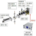
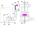
도 1은 마이크로파 응용장치의 상면도 및 측면도이다. 마이크로파 응용장치의 전체 구성은 마그네트론(Magnetron ; 111), 도파관(Waveguie ; 112), 서큘레이터(Circulator ; 113), 3-스텁튜너 (3stub-tuner ;115), 애플리케이터 (Applicator ; 117), sliding short circuit (119), 마르네트론에 전원을 조절하여 공급하는 전력공급기 혹은 파워(Power ; 121)로 구성된다. 즉 파워에서 마그네트론(Magnetron ; 111)의 필라멘트와 양극에 전원을 공급하면 마그네트론에서 생성된 마이크로파는 도파관을 통하여, 서큘레이터(Circulator ; 113), 3-스텁튜너 (3 stub-tuner ; 115)를 거쳐 애플리케이터(Applicator, 응용기 ; 117)에 전달된다. 1 is a top and side view of a microwave application. The overall configuration of the microwave application consists of a magnetron (111), a waveguide (112), a circulator (113), a 3-stub-tuner (115), an applicator (117), sliding
3-스텁튜너란 도파관 또는 공동(空胴) 공진기 내의 3개의 금속봉이 있는 장치로서 마이크로파가 반사되지 않고 최대한 전달되도록 하는 정합(matching, 整合)장치이다. 플런저(Plunger) 혹은 슬라이딩 숏써킷(Sliding Short Circuit : SSC) 역시 반사파를 최소화하기 위하여 정합을 위하여 부가적으로 장착하는 장치이다. 때로는 3-스텁 대신에 4-스텁을 사용하기도 한다. 또한, 수동으로 각 스텁을 수동으로 조절하여 정합하기도 (Manual Tuning) 하나 정합 알고리즘에 의한 자동정합 (Automatic Tuning)을 하기도 한다. 자동정합기는 스텁과, 다이오드, 통합 자동제어보드, 모토 드라이브 유니트로 구성되어 있으며 이로서 부하 임피던스를 ?주어 정합한다. 정합에 대하여 좀 더 자세하게 설명하면 다음과 같다. 일반적으로 두 회로를 결합할 경우 제1 회로의 출력 단자에서 같은 회로의 입력 단자를 본 임피던스를 Z1=R1+jX1, 제2 회로의 입력 임피던스를 Z2=R2+jX2로 했을 경우 두 임피던스 사이에 공역(共役)의 관계, 즉 R1=R2, X1=-X2가 있으면 손실 최소, 출력 최대인 조건이 얻어진다. 여기서 제1회로는 정합기, 제2 회로는 애플리케이터이다. 즉,정합이란 신호 전송로에서 최대 출력을 전송하기 위한 방법이다. 정합의 원리는 신호원이 내부 저항을 가지고 있고 최대 출력 전송을 위해서 부하는 신호원의 임피던스와 동일해야 한다. 능동 소자가 포함되어 있는 곳에서는 입력 임피던스와 출력 임피던스가 상당히 다르다. 그러나 입력 임피던스는 신호원에 정합될 필요가 있고, 출력 부하는 출력 임피던스에 정합되어야 한다. 전력 증폭기와 많은 능동 소자는 내부 전력 손실과 직선성의 요구 조건에 의해 부과된 제한 때문에 기본적 원리에서 벗어난다. 출력 부하 임피던스는 이러한 제한 조건에서 최대 출력 전송이 이루어지도록 임피던스가 정합되어 최적으로 선택되어야 한다. 정합을 하는 방식에는 도체 봉에 의한 정합, 도파관내 도체판 창에 의한 정합, 무반사 종단회로에 의한 정합, 테이퍼 도파관에 의한 정합, 변성기(/4 임피던스 변환기)에 의한 정합 등 여러 종류의 정합방법이 있다. 도 2에 예시한 바와 같이 3-스텁튜너의 경우는 도파관의 넓은 면에서 도파관내로 도체봉을 삽입하여 정합을 시키는데, 도파관에 반사파가 존재하는 경우 도체봉에 의한 전자계에 의해 반사파를 상쇄시킨다. 플런저 정합방식은 도파관내 도체판 창에 의한 정합방식으로서 도파관내에서 관측에 직각으로 도체판과 같은 장애물을 간격을 떼어서 삽입하고 부하까지의 거리를 적당히 선정하여 정합을 시키는 방식이다. 도 1과 도 2의 경우는 3-스텁튜너 정합방식과 플런저 정합방식을 혼용한 경우이다. A three-stub tuner is a device with three metal rods in a waveguide or cavity resonator, which is a matching device that allows microwaves to be transmitted without reflection. The plunger or sliding short circuit (SSC) is also an additional device for matching to minimize reflected waves. Sometimes 4- stubs are used instead of 3-stubs. In addition, manual tuning of each stub may be performed by manual tuning, or automatic tuning may be performed using a matching algorithm. The automatic matcher consists of a stub, a diode, an integrated automatic control board, and a motor drive unit, which match the load impedance. The more detailed description of matching is as follows. In general, when two circuits are combined, when the input terminal of the same circuit is seen at the output terminal of the first circuit and the impedance of Z1 = R1 + jX1 is set, and the input impedance of the second circuit is Z2 = R2 + jX2, the airspace is between the two impedances. If there is a relationship (i), that is, R1 = R2 and X1 = -X2, a condition of loss minimum and output maximum is obtained. The first circuit is a matcher and the second circuit is an applicator. That is, matching is a method for transmitting the maximum output in the signal transmission path. The principle of matching is that the signal source has internal resistance and the load must be equal to the impedance of the signal source for maximum output transmission. Where active elements are included, the input impedance and output impedance are quite different. However, the input impedance needs to match the signal source, and the output load must match the output impedance. Power amplifiers and many active devices deviate from the basic principle because of the limitations imposed by internal power loss and linearity requirements. The output load impedance should be chosen optimally by matching the impedance to ensure maximum output transfer under these constraints. There are several types of matching methods, such as matching by conductor rod, matching by conductor plate window in waveguide, matching by non-reflective termination circuit, matching by taper waveguide, and matching by transformer (/ 4 impedance converter). have. As illustrated in FIG. 2, in the case of the 3-stub tuner, the conducting rod is inserted into the waveguide at the wide side of the waveguide to match. When the reflected wave is present in the waveguide, the reflected wave is canceled by the electromagnetic field caused by the conductor rod. The plunger matching method is a matching method based on the conductor plate window in the waveguide. The plunger matching method inserts obstacles such as the conductor plate at a right angle to the observation in the waveguide, and selects a suitable distance to the load. 1 and 2 show a case where a 3-stub tuner matching method and a plunger matching method are mixed.
마이크로파가 애플리케이터에서 흡수되지 않고 반사되어 돌아오는 경우, 이 반사 마이크로파는 마그네트론에 치명적인 피해를 줄 수 있는데, 이 경우에 반사파의 방향을 전환시켜 마그네트론을 보호하며, 방향전환이 된 반사파는 더미로드 (Dummy Load ; 123)에서 그 에너지가 흡수된다. 더미로드에는 냉각수가 공급되어 흡수된 열을 외부로 방출한다. 마그네트론에서 발진되는 마이크로파의 진행방향으로 전파되는 전력을 순방향 전력 (Forward Power ; 順方向電力 혹은 입사파전력 혹은 진행파전력) 이라 하며, 애플리케이터에서 흡수되지 않고 돌아가는 전력을 반사파 전력(Reflected Power, 反波射電力) 혹은 역류파 전력이라 한다. 정합이 안 되어 마이크로파가 돌아오는 반사파는 그대로 전달되는 경우 고가품인 마그네트론(111)을 손상시키기 때문에 이러한 반사파를 서큘레이터(113)에 내재된 자석에 의하여 별도로 반사파의 방향을 전환시킨 후 더미로드(123)에 있는 흡수체에 흡수하여 소멸하도록 한다. 열을 흡수하는 더미로드(123), 열이 발생되는 마그네트론(111)과 파워공급모듈 혹은 전력공급기(121)는 온도가 상승되지 않도록 공기 혹은 냉각수를 공급하여 냉각하며, 이 냉각수에 흡수된 반사파에너지는 외부로 방출된다. 이러한 순방향전력과 반사파전력을 측정하기 위하여 써큘레이터와 3스텁튜너 사이에 방향성결합기 (Directional Coupler)를 설치하기도 한다. 도파관에 2개의 마이크로파를 측정할 수 있는 포트를 만들어서 하나는 포트의 방향이 응용기로 향하게 하여 순방향전력을 측정하고, 다른 한개는 반대방향, 즉 마그네트론쪽으로 위치하여 반사파전력을 측정하는데 사용한다. If the microwaves are reflected back from the applicator without being absorbed, the reflected microwaves can cause catastrophic damage to the magnetrons, in which case they divert the reflected waves to protect the magnetrons. The energy is absorbed in the load (123). The dummy rod is supplied with cooling water to release the absorbed heat to the outside. The power propagated in the traveling direction of the microwave generated from the magnetron is called forward power, or the power returned without being absorbed by the applicator is the reflected power. This is called electrostatic or backflow power. If the reflected wave that is not matched and the microwave is returned as it is, it damages the
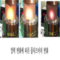
마이크로파를 이용한 플라즈마 발생장치의 조립도를 도2에 예시하였다. 도3은 이러한 마이크로파를 이용하여 플라즈마를 발생한 사진들을 보여 주고 있다. 중요한 공정변수인 압력을 변화하며 각 압력에서의 플라즈마가 발생한 사진들을 예시하고 있다.2 illustrates an assembly diagram of a plasma generator using microwaves. 3 shows photographs of plasma generated using such microwaves. Changes in pressure, an important process variable, illustrate the generation of plasma at each pressure.
마이크로파를 음식을 가열하여 익히거나 해동하는 데 사용하는 가정용 조리기의 예시도를 도 4에 나타내었다. 이 경우에는 로드 임피던스를 계산하여 설계하였고 가열하는 목적의 응용장치이므로 플라즈마의 응용분야에 비하여 장치가 간단하다.An illustration of a home cooker using microwaves to heat or cook food is shown in FIG. 4. In this case, the load impedance is calculated and designed and Applied devices are simpler than plasma applications.
마이크로파가 전달되는 관로인 도파관(waveguide)은 파(波)를 가두어 유도시켜 전파하는 임의의 구조체로서. 주로, 전자파가 진행하도록 만든 속이 비어있는(hollow) 도체금속관을 지칭한다. 도파관은 고출력(high-power), 낮은 손실(low-loss), 밀리미터파시스템등에 응용되며, 사용례로는 전술한 바와 같이 레이더, 위성중계기, 방송용 전파 송출 혹은 가열용, 플라즈마 발생 등 전자기파의 전달을 위하여 사용된다. 도파관의 구조 형태는 전자기파 도파 공간을 둘러싸는 금속도체(구리, 황동, 알루미늄등)로서 기계적 강도를 위해 도체 두께를 1~3 mm 정도로 충분히 확보되어야 하며, 또한, 응용 주파수범위에서 표피 침투 깊이의 수 배가 되도록 한다.A waveguide, which is a channel through which microwaves are transmitted, is an arbitrary structure that traps, guides, and propagates waves. It refers mainly to the hollow conductor metal tube which makes electromagnetic waves propagate. Waveguides are applied to high-power, low-loss, millimeter wave systems, etc. As examples of use, waveguides can be used to transmit electromagnetic waves such as radars, satellite repeaters, broadcasting radio waves or heating, and plasma generation. To be used. The structure of the waveguide is a metal conductor (copper, brass, aluminum, etc.) that surrounds the electromagnetic waveguide space, and should be sufficiently secured with a conductor thickness of 1 to 3 mm for mechanical strength, and the number of skin penetration depths in the application frequency range. Make it double.
국제전파협회에서 통신용으로 주로 사용하는 통신주파수 이외의 산업분야, 과학분야, 의료분야를 (Industrial, Scientific, Medial : ISM) 위하여 허용한 마이크로파의 주파수는 2.45GHz와 915MHz(0.915GHz)이다. 2.45GHz 마이크로파의 경우에 사용되는 도파관의 규격은 WR-284(내부크기: 72.14 x 34.04 mm), WR-340 (내부크기: 86.36 x 43.18 mm), WR-430 (내부크기: 109.22 x 54.61 mm)을 주로 사용하며, 915MHz의 경우에는 WR-975 (내부크기: 247.65 x 43.18 mm)도파관을 사용한다. 이와 같이 통상적으로 도파관의 크기는 마이크로파의 주파수에 따라 결정된다. 도파관은 WR-2300(내부크기: 584.2 x 292.1 mm ; 사용주파수 0.32~0.49 GHz) 부터 WR-3 까지 (내부크기: 0.86 x 0.43mm ; 사용주파수 217~333 GHz) 다양하다. 사용주파수가 커질수록 도파관 내부크키가 작아진다.The frequencies of microwaves allowed for industrial, scientific, and medical fields (Industrial, Scientific, Medial: ISM) other than those used by the International Radio Association for communication are 2.45 GHz and 915 MHz (0.915 GHz). Waveguides used for 2.45 GHz microwave are WR-284 (internal size: 72.14 x 34.04 mm), WR-340 (internal size: 86.36 x 43.18 mm), WR-430 (internal size: 109.22 x 54.61 mm) For 915 MHz, the WR-975 (internal size: 247.65 x 43.18 mm) waveguide is used. As such, the size of the waveguide is typically determined according to the frequency of the microwave. Waveguides range from WR-2300 (internal size: 584.2 x 292.1 mm; frequency of use 0.32-0.49 GHz) to WR-3 (internal size: 0.86 x 0.43mm; frequency of use 217-333 GHz). The higher the frequency used, the smaller the internal wave height of the waveguide.
마이크로파 발진기에서 조사부인 마이크로파 에너지의 전송으로, 전선은 마이크로파를 외부로 방사하기 때문에 사용할 수 없으며, 통상 도파관으로 불리는 금속 중공형 파이프가 사용된다. 도파관은 단면형상에 따라 사각형 또는 원형 도파관, 복잡한 형상의 릿지형 도파관이 있다. 일반적으로 이용되는 것은 사각형 도파관이며, 원형, 릿지형 도파관은 특수한 목적으로 사용한다. In the microwave oscillator, the transmission of microwave energy, which is an irradiation part, cannot be used because the electric wire radiates microwaves to the outside, and a metal hollow pipe commonly referred to as a waveguide is used. Waveguides are rectangular or circular waveguides according to the cross-sectional shape, and ridge waveguides of complex shape. Commonly used are rectangular waveguides, and circular and ridge waveguides are used for special purposes.
통상적으로 마이크로파를 전달하는 도파관은 사각관의 형태이며 퍼지는 특성을 지닌 마이크로파를 사각관에 가두어 전달하며, 보통 전도도가 좋은 황동이나 구리로 제작된다. 따라서 이러한 사각 도파관은 마이크로파를 이용한 공정이나 장치의 설치시 장비가 무거워지고 커지며, 조립이 어려워진다. 특히 저전력의 경우에도 장치가 중후장대하여서 설치의 어려움과 응용이 제한되어 진다. 이러한 마이크로파 전달장치를 (도 1과 도 2 참조) 이용한 플라즈마 발생장치의 예를 도 6에 예시하였다. In general, a waveguide that transmits microwaves is in the form of a square tube and traps the microwave having the propagating property in the square tube and is usually made of brass or copper with good conductivity. Therefore, such a square waveguide is heavy, large, and difficult to assemble in the installation of a microwave process or apparatus. In particular, even in the case of low power, the installation is limited due to the heavy and heavy equipment. An example of a plasma generator using such a microwave delivery device (see FIGS. 1 and 2) is illustrated in FIG. 6.
마이크로파 전송용에는 도파관 이외에 동축케이블(동축관)이 있다. 주파수가 높아 질수록 파가 외부로 쉽게 빠져 나간다는 것이 문제점이 되는데, 60Hz 이상의 주파수의 경우에 파가 외부로 빠져 나가는 것을 줄이기 위하여 폐쇄도파관을 사용한다. 폐쇄도파관방식으로 동축케이블 (Co-Axial Cable), 금속도파관(Metallic WaveGuide), 스트립라인(Strip Line)방식 등이 있다. 동축케이블은 일반 전력송신라인(Power Transmission Line) 혹은 와이어 (Twisted Wire 2줄의 전선을 꼬아 놓은 케이블) 보다 더 높은 주파수 신호를 보낼 수 있도록 내부도체에 절연체로 둘러싸고 외부 도체를 쉴딩(shielding)을 하는 형태로 외부도체로 인해 파가 케이블 밖으로 빠져 나가는 것을 줄이기 위한 형태이다. Microwave transmissions include coaxial cables (coaxial tubes) in addition to waveguides. The problem is that the wave easily escapes to the outside as the frequency increases. For frequencies above 60 Hz, a closed waveguide is used to reduce the wave exiting to the outside. Closed waveguides include co-axial cables, metallic waveguides, and strip lines. Coaxial cable is used for shielding the outer conductor with the insulator around the inner conductor so that it can send higher frequency signals than the regular power transmission line or wire (twisted wire twisted pair). It is a form to reduce the wave coming out of the cable by the external conductor.
동축케이블은 도체로 만들어진 파이프 중심축에 폴리에틸렌으로 지지되는 중심도체를 가진 전송선로이며, 파워모니터의 출력 신호전송에 이용한다. 동축케이블은 가연성이며, 취급이 용이하지만, 마이크로파 전송에너지의 전력허용치가 작다. 임피던스 50ohm을 맞추어서 저손실 동축케이블의 경우에 마이크로파 전송에너지의 최대 전력허용치는 주파수 2.45 GHz의 경우에는, 330 Watt (외경 10mm) ~ 520Watt정도 (외경 15mm)이고 주파수 915 MHz의 경우에는, 330 Watt (외경 10mm) ~ 520Watt정도 (외경 15mm)이고 580 Watt (외경 10mm) ~ 900Watt (외경 15mm)정도이다. 동축케이블은 고주파가열장치에 사용하지만 마이크로파가열 장치에는 300 ~ 500 W 이상의 고전력에서는 이용하지 않는다.Coaxial cable is a transmission line having a center conductor supported by polyethylene on a pipe central axis made of a conductor, and used for output signal transmission of a power monitor. Coaxial cables are flammable and easy to handle, but have a small power allowance for microwave transmission energy. For low loss coaxial cable with an impedance of 50 ohms, the maximum power allowance for microwave transmission energy is between 330 Watts (10 mm outside) and 520 Watts (15 mm outside) for frequencies 2.45 GHz and 330 Watts (for outside frequencies 915 MHz). 10mm) ~ 520Watt (outer diameter 15mm) and 580 Watt (outer diameter 10mm) ~ 900Watt (outer diameter 15mm). Coaxial cable is used for high frequency heating devices, but not for high power over 300 ~ 500W for microwave heating devices.
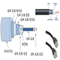
전송선로 및 도파관의 차이는 TEM 모드에 의해 전파하는 전송선로 (동축선로 포함)도 도파관으로 볼 수 있으나, 일반적으로 TEM 모드에 의한 전파 전달은 도파관이라고 하지 않는다. 즉, 주로 TE 모드(Transverse Electric Field/Wave, 횡방향 전계 ) 및 TM 모드(Transverse Magnetic Field/Wave, 횡방향 자계)에 의한 전파만을 도파관이라는 표현을 쓴다. 전송선로의 모양 형상은 2개 이상의 도체로 구성되는데, 2개의 도체가 유전체에 의해 격리되어있는 구조이다. 에너지 전달 방식은 2개 도체에 흐르는 왕복 전류/전압 파동 형태로 에너지가 전달된다. 전파 형태는 전자기파 형태로 볼 때에는 TEM 파로 전달되며, 전류파, 전압파의 전달에 의한다. 차단주파수 없기 때문에, 직류부터 매우 높은 주파수까지 동작이 가능하며, 저출력, 다소 낮은 주파수에 응용하나, 초고주파 대역에서는 표피효과 및 유전체 손실로 인해 비효율적이다. 동축케이블은 전송선로의 일종으로 통상적으로 2선식 평행케이블은 표피효과(Skin Effect)로 인해 높은 주파수에서는 도선의 실효 저항이 상승하는 결함이 생기는데 이를 보완하기 위해 개발된 것이 동축케이블이며, 그 형태는 도5와 같다. 상기한 동축케이블 구조를 상세히 살펴 보면, 2개의 원통형 도체및 유전체가 중심축을 공유하고 내부 도체는, 실제적인 신호전송을 위하여 사용되며 외부 도체는, 알루미늄/구리로 만들어진 그물 모양의 차폐용 실드(Shield)(편조 또는 박지)이며, 그 사이를 유전체/절연체(폴리에틸렌등)로 채워서 분리하여 만들어진다. 가장 바깥쪽에는 외피 피복에 케이블 재킷(비닐,폴리에틸렌 등)으로 둘러 쌓인다.The difference between the transmission line and the waveguide is that the transmission line (including the coaxial line) that propagates in the TEM mode can be seen as a waveguide, but in general, the propagation transmission in the TEM mode is not called a waveguide. In other words, the waveguide is used mainly for propagation in the TE mode (Transverse Electric Field / Wave) and the TM mode (Transverse Magnetic Field / Wave). The shape of the transmission line consists of two or more conductors, two conductors separated by a dielectric. In the energy transfer method, energy is transferred in the form of a reciprocating current / voltage wave flowing through two conductors. The propagation form is transmitted as a TEM wave when viewed in the form of electromagnetic waves, and is transmitted by current waves and voltage waves. Because there is no cutoff frequency, it can operate from DC to very high frequency, and it is applied to low power, rather low frequency, but it is inefficient due to skin effect and dielectric loss in ultra high frequency band. Coaxial cable is a type of transmission line. In general, two-wire parallel cable has a defect that increases the effective resistance of wire at high frequency due to skin effect. Coaxial cable was developed to compensate for this. Same as FIG. Looking at the above coaxial cable structure in detail, two cylindrical conductors and dielectrics share a central axis, the inner conductor is used for the actual signal transmission, and the outer conductor is a mesh-shaped shield made of aluminum / copper. (Braided or foiled), separated by filling them with a dielectric / insulator (polyethylene etc.). On the outermost side, the outer jacket is surrounded by a cable jacket (vinyl, polyethylene, etc.).
상기한 동축케이블의 장점은 외부적인 간섭이 거의 영향을 미치지 못하는 차폐된 구조를 가진 전송선로이며, 도파관처럼 차단주파수가 없기 때문에 직류 (DC)부터 마이크로파, 밀리미터파까지 사용가능하다. 현재 단거리에서는 약 50 이상 까지도 가능하다. 그러나, 수 GHz 대역이상은 거리에 따라 손실이 커서, 도파관구조를 사용하게 되고, 외경이 작으면 작을수록 더 높은 고주파사용이 가능하나, 운반 가능한 전력이 제한되며, 제작에 어려움이 있다. 전파모드는 일반적으로 TEM 모드에서 동작한다. 용도는 장거리전화망, CATV, 비디오전송, 구내정보 통신망 등(통상 1GHz 이하 많이 사용)에서 사용된다. An advantage of the coaxial cable is that the transmission line has a shielded structure with little influence from external interference, and since there is no cutoff frequency like a waveguide, it can be used from direct current (DC) to microwave and millimeter wave. At present, short distances of up to about 50 are possible. However, more than a few GHz band, the loss is large depending on the distance, the waveguide structure is used, the smaller the outer diameter, the higher the frequency can be used, the power that can be carried is limited, there is a difficulty in manufacturing. Propagation mode generally operates in TEM mode. It is used in long distance telephone network, CATV, video transmission, local area communication network, etc. (commonly used below 1GHz).
동축케이블의 커넥터는 BNC, TNC, FT-type, N-type, F-type, 미니어처타입(SMA, SMB, SMC)등을 사용한다. 동축케이블은 보통 UHF이하의 주파수에서 전송선로로 많이 사용되지만 그 이상의 마이크로파 회로에서도 내부도체는 강선에 은도금을 사용하여 신호가 도체표면의 은도금부분을 통하여 흐르도록 하여 마이크로파 대역에서 표피효과 (Skin Effect)로 인한 손실을 낮게 하고, 절연체로는 테프론 같은 재질을 사용하여 유전체 손실을 낮추어 사용하기도 한다.Coaxial cable connector uses BNC, TNC, FT-type, N-type, F-type, miniature type (SMA, SMB, SMC). Coaxial cables are commonly used as transmission lines at frequencies below UHF, but even in microwave circuits above, internal conductors use silver plating on steel wires so that signals flow through the silver plated portion of the conductor surface. Due to the low loss, the dielectric material is used to reduce the dielectric loss, such as Teflon.
저전력의 마이크로파를 사용하는 경우에는 도파관 대신에 동축케이블을 사용하여 부피, 무게 등을 감소하여 설치하는 방법이 있다. 도 6에 예시된 마이크로파를 이용한 플라즈마 발생장치를 예로 들어 설명하면 다음과 같다. 마그네트론(‘M’라 칭함), 써큘레이터(‘C’라 칭함), 더미로드(‘D’’라 칭함)등이 외부에 있으면 별도의 공간을 차지하므로 이 마그네트론, 써큘레이터, 더미로드를 전원공급장치에 내부에 설치하여 일체화 및 일원화를 한다. 이와같이 하여 상당한 공간적인 축소가 가능하며 마그네트론에 공급하는 전원을 내부에서 직접 연결하여 공급하고 냉각라인 등을 공유하는 등 동선이 작아지고 설치가 용이한 장점이 있다. 3스텁-튜너(매처 혹은 정합기 )는 수동인 경우에는 스텁을 동작하여야 매칭을 하여야 하므로 외부에 위치시킨다. 자동튜너의 경우에는 도 7에 예시한 바와 같이 임피던스를 매칭하기 위하여 스텁들이 자동으로 조절되므로 이 경우에는 튜너가 전력공급기 안으로 위치하는 것이 가능하다.In the case of using low-power microwave, there is a method of reducing the volume, weight, and the like by using a coaxial cable instead of the waveguide. Referring to the plasma generating apparatus using a microwave illustrated in Figure 6 as an example. When the magnetron (called 'M'), circulator (called 'C'), and dummy rod (called 'D') are outside, they occupy a separate space. It is installed inside the feeder to integrate and unify. In this way, it is possible to considerably reduce the space, and to connect the power supply to the magnetron directly from the inside, and to share the cooling line, there is an advantage that the copper wire is small and easy to install. The 3 stub-tuner (matcher or matcher) is located outside because it must be matched only when the stub is operated. In the case of the auto tuner, as shown in FIG. 7, the stubs are automatically adjusted to match the impedance, so in this case it is possible for the tuner to be placed into the power supply.
도 6과 도 7의 경우에는 아이솔레이터(써큘레이터와 더미로드의 합을 아이솔레이터라고 함)부터 애플리케이터까지 도파관을 사용하여 연결하여야 함으로써 불편함이 있다. 이러한 부분을 해소하기 위하여, 본 발명에서는 마이크로파의 도파관 전송방식을 동축케이블 전송방식으로 전환하는 방법을 개시한다. 즉, 도파관을 동축케이블로 전환하는 도파관-동축(케이블) 전환어댑터(Co-Axial Adaptor)를 사용하면 도파관대신에 동축케이블을 사용하여 애플리케이터(117)에 최종적으로 연결하여 마이크로파를 전달할 수 있다. In FIG. 6 and FIG. 7, it is inconvenient to connect the isolator (the sum of the circulator and the dummy rod is called an isolator) to the applicator using a waveguide. In order to solve such a part, the present invention discloses a method of converting a microwave waveguide transmission method into a coaxial cable transmission method. That is, when a waveguide-coaxial adapter is used to convert the waveguide into a coaxial cable, a coaxial cable may be used instead of the waveguide to finally connect to the
이 경우에 추가적으로 설치공간이 감소하며 설치를 용이하게 할 수 있다는 장점이 있다. 도 8과 도 9는 각각 튜너가 전력공급기 외부에 있는 경우(도 6)와, 튜너가 전력공급기 내부에 있는 경우(도 7)에 도파관-동축케이블 전환 어댑터를 설치하여 간소화하여 사용하는 경우를 보여주는 예시도이다. 도 8과 도 9에서는 튜너의 도파관 플랜지에 도파관-동축케이블 전환어댑터을 연결하여 동축케이블로 전환하고 다시 도파관-동축케이블 전환어댑터를 사용하여 애플리케이터에 연결하여 사용하는 실시예를 보여준다. 즉, 튜너 -> 도파관-동축케이블 전환어댑터 -> 동축케이블 -> 동축케이블-도파관 전환어댑터를 연결하여 사용하는 방법이다. 도 8과 도 9의 차이는 튜너가 전력공급장치박스에 내재하는 경우(도9)와 전력공급장치박스 밖에 외재하는 경우 (도 8)이다. 상기한 바와 같이 본 발명에서는 도파관-동축케이블 전환 어댑터(Co-Axial Adaptor)와 동축케이블을 사용하여 마이크로파 장치를 간소화하는 것을 특징으로 한다. 또한 본 발명에서는 아이솔레이터와 정합기를 전력공급기 안에 내재하여 동축케이블로 연결하여 설치가 용이하게 하는 방법도 포함한다. In this case, there is an additional advantage that the installation space is reduced and can be easily installed. 8 and 9 respectively show the case where the tuner is installed outside the power supply (FIG. 6) and when the tuner is inside the power supply (FIG. 7) by simply installing a waveguide-coaxial cable conversion adapter. This is an illustration. 8 and 9 show an embodiment in which the waveguide-coaxial cable switching adapter is connected to the waveguide flange of the tuner to convert to a coaxial cable and then connected to an applicator using the waveguide-coaxial cable switching adapter. That is, it is a method of connecting a tuner-> waveguide-coaxial cable adapter-> coaxial cable-> coaxial cable-waveguide converter. The difference between FIG. 8 and FIG. 9 is the case where the tuner is inherent in the power supply box (FIG. 9) and in the case outside the power supply box (FIG. 8). As described above, the present invention is characterized by simplifying the microwave device using a waveguide-coaxial adapter and a coaxial cable. In addition, the present invention also includes a method of integrating the isolator and matching device in the power supply to facilitate installation by coaxial cable.
마이크로파가 전달되는 경로에 3-스텁튜너와 아이솔레이터가 필요로 하지 않도록 정확한 임피던스 매칭을 위한 길이를 사전에 설계하여 특정화하는등의 방법을 사용하여 장치를 구성하는 경우에 마이크로파 응용장치가 훨씬 간소화될 수 있다. 이러한 경우 이외에 , 특히 플라즈마발생등의 경우에는 임피던스 매칭을 위하여 튜너(정합기)를 사용하여야 한다. 종래의 튜너(115)를 사용하지 않는 방법으로는 종래 방식의 3스텁방식의 튜너 대용으로 플런저(119)를 애플리케이터(117)와 융합하여 사용하는 방법이 있다 (도 1~도 2, 도 7~도 9 참조). 본 발명에서는 플런저 형태로 임피던스를 정합하여 사용하는 방법을 포함한다. Microwave applications can be greatly simplified if the device is constructed using methods such as pre-designing and specifying lengths for accurate impedance matching so that 3-stub tuners and isolators are not needed in the path through which the microwaves are delivered. have. In addition to these cases, especially in the case of plasma generation, a tuner (matcher) must be used for impedance matching. As a method of not using the
또한 종래의 마그네트론과 튜너(정합기)를 사용하지 않고 이러한 종래방식 대용으로 반도체초고주파 발생 모듈을 사용하고, 또한 이의 발생주파수를 변조하여 튜닝하여 (FVTM) 사용하거나, 혹은 동축튜너 혹은 플런저를 애플리케터와 융합하여, 임피던스를 정합하여 사용하는 경우에 마이크로파 장비를 훨씬 더 간소화하여 사용할 수 있다. 본 발명에서는 이러한 주파수 변조방식 (FVTM) 혹은 플런저 형태의 정합방법이 구비된 애플리케이터 방식을 포함한다. 이에 대한 상세한 방법은 후술한다.In addition, instead of using a conventional magnetron and a tuner, a semiconductor ultra-high frequency generation module is used instead of the conventional method, and the frequency is modulated and tuned (FVTM), or a coaxial tuner or plunger is used. In combination with, the microwave equipment can be used much simpler when used with matching impedances. The present invention includes an applicator method equipped with such a frequency modulation method (FVTM) or a plunger type matching method. Detailed method thereof will be described later.
상기한 도 1 내지 도 9의 경우와 같이 종래의 마이크로파를 발진하는 마그네트론을 사용하는 방법을 지양하기 위하여 최근에는 마그네트론 대신에 반도체소자를 이용하여 마이크로파를 발진하며, 이를 반도체 마이크로파 (Solid-State Micro-Wave : SSMW) 방식이라고 한다. 이 때 사용하는 반도체는 실리콘 기반의 횡확산 금속산화물반도체 [Laterally Diffused-Metal Oxide Semiconducotor LDMOS] 전계효과(電界效果) 트랜지스터(Field-Effective Transistor ; FET )이다. In order to avoid the method of using a magnetron that oscillates a conventional microwave as in the case of FIGS. 1 to 9, the microwave is oscillated using a semiconductor device instead of a magnetron. Wave: SSMW). The semiconductor used in this case is a silicon-based, lateral-diffused-metal oxide semiconducotor LDMOS field-effect transistor (FET).
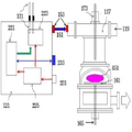
도 10에 반도체 마이크로파 전력 공급기를 사용한 플라즈마 발생장치를 예시하였다. 반도체 마이크로파 발생장치는 기존에 사용한 마그네트론 대신에 반도체를 사용하여 마이크로파를 발진시키는 방식이다. 반도체 마이크로파 발생모듈은 직류전원의 공급이 필요하므로 전력공급기(121)에 공급된 교류입력 전원(231)을 직류로 변환하기 위하여 교류-직류전환 인버터(225)를 포함하며, 인버터는 전력제어보드 (Control Board ; 221)와 반도체 마이크로파 발생모듈(223)에 전력을 공급한다. 또한 공급해야할 마이크로파 전력을 설정 및 제어하기 위하여 전력제어보드는 통신용 게이트웨이(GateWay ; 233)를 통하여 외부와 신호를 주고 받는다. 외부와 통신하는 방식으로는 Analog, Profibus, CanOpen, or Modbus RS232/RS485 등이 있다. 동작시 반도체 마이크로파 모듈에서 정합이 제대로 이루어지지 않는 경우 반사파등이 발생하여 이를 냉각하기 위하여 냉각라인(131)을 설치한다. 냉각방식은 공랭의 경우에 냉각수를 공급할 필요 없이 팬만 설치하고 팬에서 공급된 공기가 열을 품고 전력공급기 외부로 방출되면 되므로 상대적으로 설치등이 간편하다. 그러나 반사파 전력이 큰 경우, 열 발생이 많고 마이크로파 반도체소자에게 치명적일 수 있으므로, 냉각수 라인을 설치하는 것이 안전하다. 10 illustrates a plasma generator using a semiconductor microwave power supply. The semiconductor microwave generator is a method of oscillating microwaves using a semiconductor instead of a magnetron. Since the semiconductor microwave generation module requires the supply of a DC power supply, the semiconductor microwave generation module includes an AC-
도 10에 냉각수 라인까지 내재된 고주파반도체 모듈에 의한 마이크로파 발생하여 애플리케이터에 전달하는 방법을 예시하였다. 도 10에 예시한 바와 같이 고주파반도체 모듈에 의해서 발생된 마이크로파는 전력공급장치단에 부착된 커넥터, 동축케이블, 동축케이블-도파관 전환어댑터를 거쳐서 애플리케이터에 전달된다. 마이크로파 전력공급기(121) 내부에 소형의 아이솔레이터(227)의 내재가 가능하며 반사파 발생하는 경우, 공급되는 파워의 즉각적인 자동감소와 중단을 통하여 반도체 마이크로파 발생장치 모듈(223)를 보호한다. 도 10에서 아이솔레이터의 냉각라인은 예시하지 않았으나 반도체 마이크로파 발생장치 모듈(223)에 공급되는 냉각라인(131)을 공유하거나 개별적으로 설치하여 사용할 수 있다. 도 11은 반도체 마이크로파 발생장치를 이용한 한 개의 선형안테나에 의한플라즈마발생을 예시한다. 반도체 마이크로파 발생 전력공급기(121)로부터 마이크로파를 발생하여 커넥터(동축) -> 동축케이블 ->커넥터(동축)를 거쳐 선형플라즈마 안테나와 연결하여 전송하고 있다. 도 11에서 마이크로파의 에너지가 전달되어 플라즈마가 발생되고 있음을 보여준다. 10 illustrates a method of generating microwaves by the high frequency semiconductor module embedded up to the cooling water line and transmitting the same to the applicator. As illustrated in FIG. 10, the microwaves generated by the high frequency semiconductor module are transmitted to the applicator through a connector, a coaxial cable, and a coaxial cable-waveguide conversion adapter attached to the power supply stage. The
도 11은 반도체 마이크로파 발생장치를 이용한 한 개의 선형안테나에 의한 플라즈마발생을 예시한다. 반도체 마이크로파 발생 전력공급기(121)로부터 마이크로파를 발생하여 커넥터(동축) -> 동축케이블 -> 커넥터(동축)를 거쳐 선형플라즈마 안테나와 연결하여 전송하고 있다. 이러한 방법에 의하여 마이크로파의 에너지가 전달되어 플라즈마가 발생되고 있음을 도 11에서 보여준다. 도 11에 예시된 바와 같이 종래의 마그네트론으로부터 발생된 마이크로파를 도파관플랜지로 연결하여, 아이솔레이터, 튜너 등을 연결하여 사용하는 방법에 비교하여 반도체 초고주파 발생모듈과 주파수변조튜닝방식을 사용하는 경우, 응용장치가 훨씬 경박단소화 되고 설치가 간편함을 볼 수 있다.11 illustrates plasma generation by one linear antenna using a semiconductor microwave generator. Microwaves are generated from the semiconductor microwave generating
이러한 반도체소자를 이용한 마이크로파 발생장치는 다음과 같은 장점이 있다. (1) 1 ~ 최대허용출력(예를 들면 최대 허용전력은 임피던스가 정합된 동축케이블의 외경에 따라 300 ~ 500Watt 정도 크기임) 1W 단위로 정확한 전력조정이 가능하다. (2)주파수는 2450MHz의 상하로 50MHz, 즉, 2450MHZ 50MHz (2400 ~ 2500 MHz 범위)의 주파수 변조가 가능하다. (3) 마그네트론 방식보다 수명이 길다. (4)전력공급기 내부에 소형의 아이솔레이터의 내재가 가능하며 반사파 발생하는 경우, 공급되는 파워의 즉각적인 자동감소와 중단을 통하여 발생장치 회로를 보호한다. (5) 부피가 작고 경량이다. (6) 입사파 전력과 반사파 전력 정확하게 측정이 가능하다. (6) 리플(Ripple)이 적고 파워 전달효율성이 높다. (7) (대면적을 카버해야할 필요성이 있는 등) 복수 개의 애플리케이터가 필요한 산업적 응용의 경우 이를 경박단소화하여 다양한 방법으로 최적화하여 설치하여 사용자의 목적을 달성할 수 있다.The microwave generator using the semiconductor device has the following advantages. (1) 1 ~ maximum allowable output (e.g. maximum allowable power is about 300 ~ 500Watt depending on the coaxial cable whose impedance is matched). (2) The frequency is up to 2450MHz, 50MHz, that is, 2450MHZ 50MHz frequency range (2400 ~ 2500MHz) is possible. (3) It has longer life than magnetron method. (4) It is possible to have a small isolator inside the power supply and to protect the generator circuit through immediate automatic reduction and interruption of the supplied power in case of reflected wave. (5) It is small in volume and light in weight. (6) Accurate measurement of incident wave power and reflected wave power. (6) Low ripple and high power transmission efficiency. (7) For industrial applications that require multiple applicators (such as the need to cover large areas), this can be achieved by minimizing the size of the applicator and installing it in various ways to achieve the user's purpose.
동축케이블을 사용하는 경우, 300 ~ 500 Watt 이하의 저전력 영역에서 적용되기는 하지만 이러한 점은 개선되는 방안이 나올 예정이며, 보다 높은 전력에서도 마이크로파의 전달이 가능하다. 또한 최대 전력 허용치가 높은 동축케이블이 나오거나 다른 전달 방식이 나오기 전이라도 응용분야에 따라, 각각의 고주파 반도체모듈에서 발진되는 마이크로파 전달장치를 복수개로 분리하여 설치함으로써(도 13, 도 14 참조) 응용장치가 필요로 하는 적절한 전력 (에너지)의 마이크로파를 분배하여 전송함은 물론 각 고주파 반도체 전력 모듈을 개별적으로 조절함으로써 응용장치의 미세 조정이 가능하다. 따라서 본 발명은 이러한 복수개의 마이크로파 전력공급기와 전송라인과 어댑터 등을 이용한 전송방식과 장치를 특징으로 하며 이를 포함한다. In the case of using coaxial cable, although it is applied in the low power range of 300 to 500 Watt or less, this will be improved, and microwave transmission can be performed at higher power. In addition, even before a coaxial cable having a high maximum power allowance or another transmission method is released, a plurality of microwave transmission devices oscillated in each high frequency semiconductor module are separately installed and installed according to the application field (see FIGS. 13 and 14). It is possible to fine tune the application by individually distributing and transmitting microwaves of the appropriate power (energy) required by the device, as well as individually adjusting each high frequency semiconductor power module. Therefore, the present invention features and includes a transmission scheme and apparatus using the plurality of microwave power supplies, transmission lines, and adapters.
마이크로파는 주파수(진동수) 300MHz ~ 30GHz, 파장으로 보면 1cm ~ 1m인 전자기파의 한 영역을 말한다. 전자기파의 영역은 진동수에 의해 임의로 구분되어지는데 진동수는 1초 동안 파동이 진동하는 횟수이다. 진동수의 단위는 Hz로 나타내며 1Hz는 1초에 파동이 1번 진동한 것을 나타낸다. 진동수(f), 파장, 빛의 속도(C)의 관계는 다음과 같다.Microwave refers to a region of electromagnetic waves with a frequency (frequency) of 300 MHz to 30 GHz and a wavelength of 1 cm to 1 m. The area of the electromagnetic wave is arbitrarily divided by the frequency, which is the number of times the wave vibrates for 1 second. The frequency unit is expressed in Hz, and 1Hz indicates that the wave vibrates once in one second. The relationship between the frequency f, the wavelength, and the speed C of light is as follows.
= C / f (1) = C / f (1)
즉, 파장이 짧을수록 진동수가 크고 파장이 긴 전자기파는 진동수가 작다. 여기서 빛의 속도 C 는 2.99792458*108 m/s 이다 . In other words, the shorter the wavelength, the higher the frequency and the longer the electromagnetic wave the lower the frequency. Where the speed C of light is 2.99792458 * 10 8 m / s.
이렇게 파장에 따라 전자기파는 가장 짧은 영역부터 감마선, x선, 자외선, 가시광선, 적외선, 마이크로파, 라디오파 등으로 구분되며, 통상 적외선 이상은 빛, 그 이하는 전파라고 한다. 즉, 마이크로파는 빛 보다는 진동수가 낮고 파장이 긴 전파지만, 전파 중에서는 진동수가 크고 파장이 짧은 편으로, 전술한 바와 같이 레이더, 내비게이션, 통신과 가열, 플라즈마 등 각종 산업분야등에 이용된다. 임피던스 매칭을 위한 전송(tansmission) 길이 Li 는 다음과 같다.According to the wavelength, electromagnetic waves are classified into gamma rays, x-rays, ultraviolet rays, visible rays, infrared rays, microwaves, radio waves, etc. from the shortest region, and in general, infrared rays or more are called radio waves. In other words, although microwaves have a lower frequency and longer wavelength than light, microwaves have a higher frequency and shorter wavelength, and are used in various industrial fields such as radar, navigation, communication and heating, and plasma as described above. The transmission length Li for impedance matching is as follows.
Li = / 4 (2) Li = / 4 (2)
상기한 전송길이에 의해서 마이크로파 전달 어댑터를 제작한다. 마이크로파를 발진하기 위하여 반도체소자를 이용하는 경우에도 임피던스의 부정합으로 반사파가 발생할 수 있다. 반도체소자를 이용한 마이크로파 장치에서는 반도체소자의 주파수를 변화가 일부 범위에서 가능하기 때문에 (식 1)과 (식 2)에 의하여 주파수를 변조하여 임피던스 매칭을 할 수 있으며, 본 발명에서는 이러한 주파수 변조에 의한 임피던스 매칭방법을 포함한다. 즉, 본 발명에서는 애플리케이터와 임피던스가 매칭이 안되거나 Li가 맞지 않아서 부정합이 되는 경우에 주파수를 조절 및 튜닝하여 정합하는 알고리즘에 의하여 반사파를 최소화 하는 것을 특징으로 한다. 즉, 반도체 모둘로부터 발생되어 출력되는 경우, 주파수를 변조하는 것이 가능하므로 이러한 주파수 변조를 통하여 정합하는 것이 가능하며 이를 주파수변조 튜닝방법(Frequency Variation Tuning Method - FVMM) 이라한다. 요약하면, 본 발명에서는 종래의 튜너(정합기)를 사용하지 않는 방법으로서 주파수 변조방식 (FVTM) 형태의 임피던스 정합방법이 구비된 마이크로파 시스템을 개시한다, 이러한 경우에 마이크로파 장비를 훨씬 더 간소화하여 용이하게 사용할 수 있다. The microwave transmission adapter is manufactured according to the above transmission length. Even when a semiconductor device is used to oscillate microwaves, reflected waves may be generated due to impedance mismatch. In the microwave device using the semiconductor element, since the frequency of the semiconductor element can be changed within a certain range, impedance matching can be performed by modulating the frequency according to (Equation 1) and (Equation 2). Impedance matching method. That is, the present invention is characterized in that the reflected wave is minimized by an algorithm for adjusting and tuning the frequency when the applicator and the impedance are not matched or the Li is not matched to match. That is, when generated and output from the semiconductor module, it is possible to modulate the frequency so that it can be matched through such frequency modulation, which is referred to as a frequency variation tuning method (FVMM). In summary, the present invention discloses a microwave system equipped with an impedance matching method in the form of frequency modulation (FVTM) as a method that does not use a conventional tuner (matcher), in which case the microwave equipment is further simplified and easily Can be used.
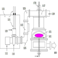
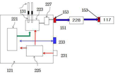
이외에도, 반도체 마이크로파 전력공급장치와 애플리케이터 사이를 동축케이블로 연결하는 경우에 그 사이에 동축 임피던스 조정장치를 사용하여 추가로 튜닝(정합)을 할 수 있으며, 이를 동축 혹은 동축 임피던스 튜너방법 (Co-Axial Impedance Tuning Method) 라 한다. 이러한 방법을 사용하는 동축 임피던스튜너(228)의 설치예를 도 12에 예시한다. 이는 반도체마이크로파 발생장치(121)와 애플리케이터 (117)사이에 설치되며 동축케이블로 연결한다. 동축 임피던스 튜너(228)에는 임피던스를 변화시킬 수 있도록 구성되어 있으며, 이는 수동 혹은 자동으로 조절이 가능하다. 즉, 마이크로파 검출센서에 의하여 측정된 반사파의 크기를 전력공급장치(121)에 디스플레이하고 이에 의하여 동축 임피던스 튜너(228)의 임피던스를 자동 혹은 수동으로 조절하여 반사파를 최소화하는 방향으로 조절하여 튜닝한다. 자동으로 튜닝하는 경우에는 마이크로파 전력공급장치(121) 내에 내재하도록 설치가 가능함을 밝힌다. 본 발명에서는 주파수변조 튜닝방법 이외에도 동축 임피던스 튜닝방법도 포함한다.In addition, when a coaxial cable is connected between a semiconductor microwave power supply device and an applicator, a coaxial impedance adjusting device can be further tuned (co-axed), which is used as a coaxial or coaxial impedance tuner method (Co-Axial). Impedance Tuning Method). An example of installation of the
또한, 본 발명에서는 3-스텁튜너(혹은 4-스텁튜너)등 종래의 방식이나 상기한 주파수변조 등의 새로운 정합방법 등과는 별도로 또 다른 정합방법으로서 애플리케이터에 플런저(Plunger)를 복합적으로 결합하여 수동 혹은 자동으로 정합이 이루어질 수 있는 방법을 개시한다. 애플리케이터(117)는 도파관 혹은 동축케이블 형태로 연결이 가능한데, 애플리케이터(117) 배후에 플런저(119)를 설치하여 튜닝하여 사용할 수 있다. 플런저(119)도 도파관 형식 혹은 동축케이블 방식이 다 가능하다In addition, in the present invention, in addition to the conventional matching method such as a 3-stub tuner (or 4-stub tuner) or a new matching method such as the frequency modulation, etc., another coupling method is a combination of the plunger and the passive. Or a method in which matching can be made automatically.
종합하면, 본 발명에서는 주파수변조튜닝, 동축 임피던스튜너(228) 혹은 플런저(119) 사용하여 임피던스 매칭하여 반사파를 최소화시켜 사용하는 방법을 포함한다.In summary, the present invention includes a method of minimizing reflected waves by impedance matching using frequency modulation tuning,
또한, 본 발명에서는 순간적인 반사파가 발생하는 경우, 이로부터 마이크로파 발생장치를 보호하기 위하여 반사파를 회절시켜 고주파반도체모듈을 보호하는 냉각라인이 구비된 아이솔레이터를 소형화하여 상기한 고주파 반도체 전력공급장치 내에 내재하는 것을 특징으로 한다.In addition, in the present invention, when an instantaneous reflected wave is generated, an isolator having a cooling line for diffusing the reflected wave to protect the high frequency semiconductor module in order to protect the microwave generator therefrom is made smaller in the high frequency semiconductor power supply. Characterized in that.
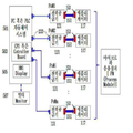
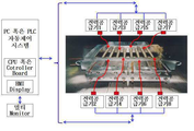
복수 개의 반도체 마이크로파발생장치에 대한 개념을 도 13에 도시하였다. 복수 개의 파워모듈(전력공급기, Power Module , PoM로 표기 ; 121)가 설치되고, 각 모듈별로 애플리케이터(응용기)가 적용이 된다. 각 애플리케이터는 전체 애플리케이터의 한 부분별 애플리케이터이거나 완전 별개의 독립적인 애플리케이터일 수 있다. 도 10에 예시된 바와 같이 각 파워공급모듈에는 각 제어보드가 있고, 외부등과 통신할 수 있는 통신시스템이 존재한다. 따라서 중앙제어컴퓨터(Personal Computer PC ; 501) 시스템 혹은 PLC(Programmable Logic Controller ; 501)에서 각 파워모듈에 대하여 중앙에서 제어가 가능하다. 외부와 통신하는 방식으로는 PC를 사용하는 경우 Modbus RS232 / RS485 방식이 있고, PLC를 사용하는 경우에는 Profibus 혹은 CanOpen, 방식 등이 있다. 중앙제어컴퓨터 시스템(501)이 각 파워모듈(121)에 대하여 원하는 전력값을 셋팅하고, 이 셋팅값의 전력을 최적화하여 찾아 들어가는 것은 각 파워모듈이 실행한다. 각 모듈이 실행후 측정된 순방향전력과 반사파전력을 통신게이트웨이(233)를 통하여 중앙제어 컴퓨터 시스템(501)에 전달한다. 중앙제어 컴퓨터 시스템(501)은 이 데이터 값들 받아 셋팅값과 디스플레이하며 비교 분석하여 응용장치의 원하는 스펙을 맞는지 파악하여 최적화 알고리즘에 따라 다음 명령을 지시한다. 통상적으로 마이크로 응용장치 옆에 설치되는 중앙제어 컴퓨터 시스템(501) 자체에 HMI (Human Machine DIsplay) 디스플레이(505)를 설치하여 현장에서 각 파워모듈(121)의 작동상태를 모니터링 한다. 누설 문제로 위험할 수 있는 마이크로 응용장치가 격리된 공간에 설치된 경우, 리모트 인터페이스장치를 통하여 별도의 제어룸(Control Room)에서 다중 모니터(Multi-Monitor ; 507)를 이용하여 복수개의 파워모듈의 각 순방향전력과 반사파전력, 정합과정 궤적 곡선을 스미스차트(Smith Chart)상에서 모니터링한다. 상기한 방법을 통하여 마이크로파 응용장치를 보다 경박단소화 할 수 있을 뿐더러 마이크로파를 분기하여 사용할 수 있으므로 동시에 사용자의 여러 목적에 회적합하게 다양한 방법으로 적용이 가능하다는 큰 장점이 있다. A concept of a plurality of semiconductor microwave generators is illustrated in FIG. 13. A plurality of power modules (denoted by power supply, Power Module, PoM; 121) are installed, and an applicator (application) is applied to each module. Each applicator can be a partial applicator of the entire applicator or a completely separate and independent applicator. As illustrated in FIG. 10, each power supply module has each control board, and there is a communication system capable of communicating with an external lamp. Therefore, it is possible to centrally control each power module from a Personal Computer PC (501) system or a PLC (Programmable Logic Controller) 501. In case of using PC, Modbus RS232 / RS485 type is used. In case of PLC, Profibus or CanOpen type is used. The central control computer system 501 sets a desired power value for each
상기한 복수개의 반도체 마이크로 파워모듈을 이용한 마이크로파를 전달하는 장치예를 도 14에 대표적으로 예시한다. 균일도를 유지하기 위하여 대면적 플라즈마를 발생하는 것은 매우 어려운 분야이다. 특히 12인치 이상의 웨이퍼나 5 ~ 8세대 이상의 LCD를 처리하기 위한 대면적 플라즈마 소스가 절대적으로 필요하다. 1개의 마이크로파 전력공급기와 1개의 애플리케이터를 이용하여 대면적 플라즈마를 균일하게 만드는 것은 매우 어려운 일이다. 또한, 각 반응 챔버의 형상, 기체의 흐름패턴, 기체의 주입구, 라디칼을 생성하여 사용하는 경우, 라디칼 디스트리뷰터의 형상등 공정 처리 조건에 맞춰 플라즈마를 제어하여 공급하는 것이 필요하며, 1개의 대면적 소스로 원하는 균일도와 쓰루풋(throughput, 반응속도) 맞춘다는 것이 거의 불가능하다. 따라서 이를 다중 소스로 분할하여 구성하여 하나의 큰 소소를 만드는 방법이 필요하다. 도 14에 보는 바와 같이 각 절연체에 감싸진 동축봉에 각 파워모듈의 전력을 공급하여 선형플라즈마(Line Plasma)를 형성하되, 이러한 선형플라즈마 안테나를 복수 개로 설치하여 플라즈마 소스를 조합 및 구성하여 대면적 플라즈마(Large Area Plasma)를 구성한다. 이러한 경우에는 다수개의 전력공급장치를 연결하여 사용하여야 하기 때문에 전체 장치를 구성하는 것이 복잡하고 비용이 많이 든다는 단점이 있다. 이를 개선하기 위한 방법으로 선형플라즈마안테나를 병렬로 집합처리하여 한 개로 동축봉에 연결하는 방법(도 15참조) 혹은 소수개로 분할병렬처리하여 연결하는 방법(도 16참조) 으로 마이크로파를 전달하는 것이 가능하다. An example of a device for transmitting microwaves using the plurality of semiconductor micro power modules is representatively illustrated in FIG. 14. Generating large area plasma to maintain uniformity is a very difficult field. In particular, a large-area plasma source is needed to process 12-inch or larger wafers or LCDs of 5-8 generations or larger. It is very difficult to make a large area plasma uniform using one microwave power supply and one applicator. In addition, when generating and using the shape of each reaction chamber, the flow pattern of the gas, the gas inlet, and the radical, it is necessary to control and supply the plasma in accordance with the processing conditions such as the shape of the radical distributor. It is almost impossible to achieve the desired uniformity and throughput. Therefore, there is a need for a method of dividing this into multiple sources to make one large source. As shown in FIG. 14, power of each power module is supplied to coaxial rods wrapped in each insulator to form a linear plasma, but a plurality of such linear plasma antennas are installed to combine and configure a plasma source to provide a large area. A plasma is composed of a large area plasma. In this case, since a plurality of power supplies must be connected and used, it is disadvantageous that the entire device is complicated and expensive. In order to improve this, it is possible to transmit microwaves by combining linear plasma antennas in parallel and connecting them to one coaxial rod (see FIG. 15) or by connecting them by dividing and paralleling them into a few (see FIG. 16). Do.
본 발명에서는 반도체 마이크로파 발생방법과 장치에 대한 새로운 방법과 일부 예만을 개시한 것으로서 플라즈마등 개별적인 응용에 대한 것은 별도의 발명으로 보다 상세하게 구체화하여 별도로 출원하고자 한다.In the present invention, only a new method and some examples of the semiconductor microwave generating method and apparatus are disclosed, and the individual application such as plasma is specifically described in detail as a separate invention and separately filed.
상기한 도 14의 예시의 경우처럼 복수개의 고주파반도체 전력모듈을 사용하는 방법 이외에 종래의 마그네트론을 사용하여 마이크로파를 발진하여 전달하는 별도의 방법도 가능하다. 각각의 여러 개의 동축안테나로 구성된 다중 선형플라즈마소스(도 14참조)의 경우에는 각각의 동축봉에 각각의 마이크로파 장치를 개별적으로 연결도 가능하다. 즉, 이러한 경우에는 도 9에 예시된 바와 같이 마그네트론, 아이솔레이터, 튜너 (양단이 도파관 형태임), 도파관-동축케이블 전환어댑터가 내재된 여러 개의 각각의 마이크로웨이브 전력공급장치에 최종 도파관-동축케이블 전환어댑터의 커넥터를 통하여 각각의 동축케이블로 연결하여 선형플라즈마소스의 각각의 동축봉에 일대일로 연결하여 사용하는 방법이다. 따라서 이 경우에는 각각의 동축봉에 각각의 마그네트론, 아이솔레이터, 튜너, 도파관-동축케이블 전환어댑터가 내재된 다수개의 전력공급장치를 연결하여 사용하여야 하기 때문에 전체 장치를 구성하는 것이 복잡하고 비용이 많이 든다는 단점이 있다.In addition to the method of using a plurality of high-frequency semiconductor power modules as in the example of FIG. 14, a separate method of oscillating and transmitting microwaves using a conventional magnetron is possible. In the case of multiple linear plasma sources (see FIG. 14) composed of several coaxial antennas, it is also possible to individually connect each microwave device to each coaxial rod. That is, in this case, as shown in Figure 9, the final waveguide-to-coaxial cable switch is applied to each of several microwave power supplies incorporating a magnetron, an isolator, a tuner (both ends in the form of a waveguide), and a waveguide-coaxial cable conversion adapter. It is connected to each coaxial cable through the connector of the adapter and connected to each coaxial rod of the linear plasma source one-to-one. Therefore, in this case, it is complicated and expensive to configure the whole device because each coaxial rod has to use a plurality of power supply devices each including magnetron, isolator, tuner, and waveguide-coaxial cable switching adapter. There are disadvantages.
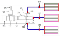
상기한 문제점을 개선하기 위하여 1개의 전력공급장치, 마그네트론과 도파관을 이용하되 마이크로파를 전달받을 선형플라즈마의 동축안테나들을 병렬로 묶어서 처리하는 것이 가능하다. 이 경우에는 마그네트론과 도파관으로 전달된 마이크로파를 동축(케이블)-도파관 전환어댑터를 사용하여 동축케이블 혹은 동축봉 형태로 전환한 후 이를 각 선형플라즈마의 동축봉을 병렬로 연결하여 처리하는 방법이다. 이러한 방법을 도 15에 예시하였다. 플라즈마를 발생시키기 위하여 진공이 필요한 경우에는 상기한 동축봉 배열판 표면에 진공을 위한 오링 혹은 메탈 가스킷 등을 배치하는 구조로 구성하여 진공상태를 유지하도록 한다. 또한, 금속봉이 응용공정에 미치는 영향(공정오염물질발생등)을 최소화하기 위하여 금속봉 주변을 절연재이면서 마이크로파가 투과할 수 있는 석영 혹은 사파이어등의 재료로 감싼다. 또한, 필요한 경우에는 금속봉과 이러한 절연재등의 양단에 진공이 유지 되도록 진공실링 어댑터 등을 설치한다.In order to solve the above problems, it is possible to use a single power supply, a magnetron and a waveguide, and process coaxial antennas of a linear plasma to receive microwaves in parallel. In this case, the microwaves transmitted to the magnetron and the waveguide are converted into coaxial cables or coaxial rods using a coaxial (cable) -waveguide conversion adapter, and the coaxial rods of each linear plasma are connected in parallel. This method is illustrated in FIG. 15. When a vacuum is required to generate a plasma, an O-ring or a metal gasket for vacuum is disposed on the surface of the coaxial rod array plate to maintain a vacuum state. In addition, in order to minimize the influence of the metal rods on the application process (process pollutant generation, etc.), the metal rod is wrapped with a material such as quartz or sapphire that is insulated and microwaves can transmit. If necessary, a vacuum sealing adapter or the like is installed to maintain the vacuum at both ends of the metal rod and the insulating material.
상기한 방법은 한 개의 마그네트론에서 발생된 마이크로파를 도파관 -> 도파관-동축케이블 전환어댑터 -> 동축케이블 -> 동축봉안테나의 순서로 연결하여 선평플라즈마소소의 다수개의 안테나를 집합하여 병렬로 연결된 최종 동축봉에 연결하여 전달하는 방법이다. 이러한 방법과는 별도로 도파관에 도파관스플리터(Spliter) 를 이용하여 분기한 후 이를 각각의 선형플라즈마안테나의 동축봉에 개별적으로 연결하거나 혹은 부분적으로 병렬집합된 동축봉에 연결하는 방법이 가능하다. 즉, 이 경우에는 도파관 -> 도파관 스플리터 -> 다수개의 도파관-동축케이블 전환어댑터 -> 다수개의 동축케이블 -> 다수개의 동축봉안테나와 연결하는 방식이다. 병렬집합된 동축봉에 연결하는 경우를 도 16에 예시하였다. 다만, 이 경우에는 한 개의 파워만을 사용하므로 각각의 선형플라즈마에 공급되는 전력과 이에 따른 각 선형플라즈마 전자온도, 전자밀도 등을 개별적으로 조절 및 제어하는 것은 어렵다. 상기한 방법과는 별도의 방법 중의 하나로 도파관 스플리터를 사용하는 방법 대신에 동축케이블 스플리터를 사용하는 것이 가능하다. 즉, 한 개의 마그네트론에서 발생된 마이크로파를 도파관 -> 도파관-동축케이블 전환어댑터 -> 동축케이블 -> 동축케이블 스플리터 -> 다수개의 동축케이블 -> 다수개의 동축봉안테나와 연결하는 방식이며, 본 발명에서는 상기한 바와 같이 다양하게 변형되거나 및 균등한 타 실시예가 가능하다는 점을 밝힌다.In the above method, the microwaves generated in one magnetron are connected in the order of waveguide-> waveguide-coaxial cable conversion adapter-> coaxial cable-> coaxial rod antenna to collect a plurality of antennas of a flat plasma element, and the final coaxially connected in parallel. It is connected to the rod and delivered. Apart from this method, it is possible to branch the waveguide using a waveguide splitter and then connect it to the coaxial rods of the respective linear plasma antennas or to the coaxial rods partially paralleled. That is, in this case, a waveguide-> waveguide splitter-> a plurality of waveguides-coaxial cable conversion adapter-> a plurality of coaxial cables-> a plurality of coaxial rod antennas. 16 illustrates a case of connecting to a parallel assembled coaxial rod. However, in this case, since only one power is used, it is difficult to individually control and control the power supplied to each linear plasma, and thus the linear plasma electron temperature and electron density. It is possible to use a coaxial cable splitter instead of the waveguide splitter as one of the methods separate from the above method. That is, the method of connecting the microwave generated from one magnetron to the waveguide-> waveguide-coaxial cable conversion adapter-> coaxial cable-> coaxial cable splitter-> a plurality of coaxial cables-> a plurality of coaxial rod antennas, As described above, various modifications and equivalent other embodiments are possible.
본 발명에서는 동축케이블 (Co-Axial Cable) 혹은 도파관을 사용하는 방식에 대하여 언급하였으나, 마이크로파를 전송라인방식으로서 스트립라인 (Strip Line) 방식 혹은 기타 방식도 포함하며 전송라인의 종류에 따라 각 라인방식에 적합한 전환어댑터를 채택하는 것을 포함한다.In the present invention, a method of using a coaxial cable or a waveguide is mentioned, but a microwave includes a strip line method or other method as a transmission line method, and each line method according to the type of transmission line. And employing a suitable adaptation adapter.
요약하면, 본 발명에서는 상기한 바와 같은 1개의 고파워와 마그네트론을 이용하여 발생시킨 마이크로파를 전환어댑터, 동축케이블 및 스플리터 등을 사용하여 다중으로 분배하는 방식으로 응용장치에 연결하여 용이하게 마이크로파를 전달하는 방법도 포함한다.In summary, in the present invention, microwaves generated by using one high-power and magnetron as described above are easily distributed by connecting to an application device by using a switching adapter, a coaxial cable, and a splitter. It also includes how to do it.
상기한 바와 같이 본 발명에서는 고주파반도체소자에 의하여 발생된 마이크로파와 전송라인과 어댑터를 통하여 이를 전달하는 마이크로파 응용장치를 특징으로 한다. 이러한 방법을 통하여 보다 무게와 부피가 작고 설치가 용이하다. 또한, 복수 개를 분리하여 설치하여 전달함으로서 다양한 분야에서 좋은 균일도, 대면적화 미세한 마이크로파 에너지의 전달 및 조절이 가능하다. 또한, 본 발명에서는 종래의 마그네트론을 사용하여 마이크로파를 발생하여 사용하더라도 도파관-동축케이블 전환어댑터와 스플리터 등을 사용하여, 보다 용이하게 개별적으로, 부분집합병렬, 혹은 총괄집합병렬처리하는 방식으로 마이크로파를 전달하는 방법을 개시하였다.As described above, the present invention is characterized by a microwave application device for transmitting it through the microwave generated by the high-frequency semiconductor device and the transmission line and the adapter. In this way, the weight and volume are smaller and easier to install. In addition, it is possible to transmit and adjust the uniformity, large area and fine microwave energy in a variety of fields by separating and installing a plurality. In addition, in the present invention, even if the microwave is generated and used using a conventional magnetron, the microwave is easily and individually subdivided or collectively paralleled by using a waveguide-coaxial cable switching adapter and a splitter. Disclosed is a method of delivery.
실시예는 예시적인 것에 불과하며, 본 발명이 속한 기술 분야의 통상의 지식을 가진 자라면 이로부터 다양한 변형 및 균등한 타 실시예가 가능하다는 점을 잘 알 수 있을 것이다.The embodiments are merely exemplary, and it will be apparent to those skilled in the art that various modifications and equivalent other embodiments are possible.
그러므로 본 발명은 상기의 상세한 설명에서 언급되는 형태로만 한정되는 것은 아님을 잘 이해할 수 있을 것이다. 따라서 본 발명의 진정한 기술적 보호 범위는 첨부된 특허청구범위의 기술적 사상에 의해 정해져야 할 것이다. 또한, 본 발명은 첨부된 청구범위에 의해 정의되는 본 발명의 정신과 그 범위 내에 있는 모든 변형물과 균등물 및 대체물을 포함하는 것으로 이해되어야 한다.Therefore, it will be understood that the present invention is not limited to the forms mentioned in the above detailed description. Therefore, the true technical protection scope of the present invention will be defined by the technical spirit of the appended claims. It is also to be understood that the present invention includes all modifications, equivalents and substitutions within the spirit and scope of the invention as defined by the appended claims.
111 : 마그네트론 112 : 도파관
113 : 서큘레이터 115 : 3-스텁튜너
117 : 애플리케이터 119 : 플런저 혹은 슬라이딩숏써킷
121 : 마이크로파 전력공급기 131 : 냉각라인
151 : 동축케이블 153 : 커넥터
155 : 동축케이블과 웨이브가이드 변환어댑터
156 : 금속동축봉
157 : 석영, 사파이어 혹은 강화유리등 절연재
159 : 금속봉과 절연재의 진공실링 어댑터
171 : 플라즈마 173 : 안테나
175 : 플라즈마 발생을 위한 동축봉 배열판
181 : 마이크로파 스플리터
161 : [웨이퍼 등] 서브스트레이트) 165 : 냉각라인이 구비된 홀더
221 : 자동제어보드 223 : 반도체 마이크로파 발생모듈
225 : 교류 -직류 전환 인버터 231 : 전원공급부
233 : 외부통신 게이트웨이 501 : PC 혹은 PLC 자동제어 시스템
503 : CPU 혹은 Cotroller Board 505 : HMI Display
507 : 멀티 모니터111: magnetron 112: waveguide
113: Circulator 115: 3-Stub Tuner
117: applicator 119: plunger or sliding short circuit
121: microwave power supply 131: cooling line
151: coaxial cable 153: connector
155: coaxial cable and waveguide conversion adapter
156: metal coaxial rod
157: insulating material such as quartz, sapphire or tempered glass
159: vacuum sealing adapter of metal rod and insulation
171: plasma 173: antenna
175: coaxial rod array plate for plasma generation
181: Microwave Splitter
161: [wafer etc. substrate] 165: holder with cooling line
221: automatic control board 223: semiconductor microwave generating module
225: AC-DC switching inverter 231: power supply
233: External communication gateway 501: PC or PLC automatic control system
503: CPU or Cotroller Board 505: HMI Display
507: multi monitor
Claims (3)
입력된 교류전원을 직류로 변환하여 마그네트론에 전원을 공급하는 교류-직류전환 인버터;
전력을 조절하여 공급하고 반사파 발생 시에 전원을 감소하거나 혹은 차단하는 자동제어보드;
외부와 신호를 주고받는 게이트웨이가 구비된 전력공급장치;
상기 전력공급장치 내에 내제하여 반사파전력이 발생하는 경우에 튜너에 의하여 반사파를 최소화하는 알고리즘;
상기 전력공급장치 내에 내재하여 반사파를 회절시켜 고주파반도체 모듈을 보호하는 아이솔레이터 ;
마이크로파를 도파관-동축(케이블) 전환어댑터를 사용하여 동축케이블 형태로 전환한 후 동축케이블에 의하여 마이크로파를 전달하는 것을 포함하는 마이크로파 시스템
A magnetron module for oscillating microwaves;
An AC-DC switching inverter for converting an input AC power into DC to supply power to the magnetron;
An automatic control board that regulates and supplies power and reduces or cuts off power when a reflected wave is generated;
A power supply device having a gateway for exchanging signals with the outside;
An algorithm which minimizes the reflected wave by the tuner when the reflected wave power is generated in the power supply device;
An isolator inherent in the power supply device to diffract reflected waves to protect the high frequency semiconductor module;
Microwave system comprising converting microwaves into coaxial cable form using a waveguide-coaxial (cable) conversion adapter and then transmitting microwaves by the coaxial cable
마그네트론과 도파관으로 전달된 마이크로파를 도파관-동축(케이블) 전환어댑터와 동축케이블을 사용하여 각각의 선형안테나의 병렬로 총집합된 동축봉들에 연결하여 처리하는 마이크로파 시스템.
The method of claim 1,
Microwave system for processing microwaves transmitted to magnetron and waveguide by connecting waveguide-coaxial (adaptable) adapters and coaxial cables to coaxial rods aggregated in parallel with each linear antenna.
마그네트론과 도파관으로 전달된 마이크로파를 도파관 혹은 동축케이블 스플리터, 도파관-동축 케이블 전환어댑터와 동축케이블을 사용하여 각각의 선형안테나의 각각의 동축봉 혹은 부분집합된 동축봉들과 개별적으로 연결하여 처리하는 마이크로파 시스템.The method of claim 1,
Microwaves, which are delivered to magnetrons and waveguides, are individually processed using waveguides or coaxial cable splitters, waveguide-coaxial cable conversion adapters, and coaxial cables, individually connected to each coaxial rod or subset of coaxial rods of each linear antenna. system.
Priority Applications (1)
| Application Number | Priority Date | Filing Date | Title |
|---|---|---|---|
| KR1020200021156A KR102383781B1 (en) | 2018-07-27 | 2020-02-20 | Microwave System |
Applications Claiming Priority (2)
| Application Number | Priority Date | Filing Date | Title |
|---|---|---|---|
| KR1020180088186A KR102267544B1 (en) | 2018-01-05 | 2018-07-27 | Microwave System |
| KR1020200021156A KR102383781B1 (en) | 2018-07-27 | 2020-02-20 | Microwave System |
Related Parent Applications (1)
| Application Number | Title | Priority Date | Filing Date |
|---|---|---|---|
| KR1020180088186A Division KR102267544B1 (en) | 2018-01-05 | 2018-07-27 | Microwave System |
Publications (2)
| Publication Number | Publication Date |
|---|---|
| KR20200021067A true KR20200021067A (en) | 2020-02-27 |
| KR102383781B1 KR102383781B1 (en) | 2022-04-05 |
Family
ID=69647444
Family Applications (1)
| Application Number | Title | Priority Date | Filing Date |
|---|---|---|---|
| KR1020200021156A KR102383781B1 (en) | 2018-07-27 | 2020-02-20 | Microwave System |
Country Status (1)
| Country | Link |
|---|---|
| KR (1) | KR102383781B1 (en) |
Cited By (1)
| Publication number | Priority date | Publication date | Assignee | Title |
|---|---|---|---|---|
| EP3893605A1 (en) | 2020-04-07 | 2021-10-13 | LG Electronics Inc. | Transfer connector with improved operational reliability |
Citations (5)
| Publication number | Priority date | Publication date | Assignee | Title |
|---|---|---|---|---|
| KR20060026424A (en) * | 2003-06-17 | 2006-03-23 | 닛테쯔 고우교 가부시키가이샤 | Gas processing method and gas processing apparatus utilizing oxidation catalyst and low-temperature plasma |
| JP2007103244A (en) * | 2005-10-06 | 2007-04-19 | Mitsubishi Heavy Ind Ltd | Vacuum processing apparatus and high frequency power supplying method in vacuum processing apparatus |
| JP2007212361A (en) * | 2006-02-10 | 2007-08-23 | Mie Tsuda Denki Sangyo Kk | Device and method for inspecting resin molded article |
| JP2010189731A (en) * | 2009-02-19 | 2010-09-02 | Nippon Telegr & Teleph Corp <Ntt> | Plasma system |
| US20140066838A1 (en) * | 2007-11-06 | 2014-03-06 | Creo Medical Limited | Microwave plasma sterilisation system and applicators therefor |
-
2020
- 2020-02-20 KR KR1020200021156A patent/KR102383781B1/en active IP Right Grant
Patent Citations (5)
| Publication number | Priority date | Publication date | Assignee | Title |
|---|---|---|---|---|
| KR20060026424A (en) * | 2003-06-17 | 2006-03-23 | 닛테쯔 고우교 가부시키가이샤 | Gas processing method and gas processing apparatus utilizing oxidation catalyst and low-temperature plasma |
| JP2007103244A (en) * | 2005-10-06 | 2007-04-19 | Mitsubishi Heavy Ind Ltd | Vacuum processing apparatus and high frequency power supplying method in vacuum processing apparatus |
| JP2007212361A (en) * | 2006-02-10 | 2007-08-23 | Mie Tsuda Denki Sangyo Kk | Device and method for inspecting resin molded article |
| US20140066838A1 (en) * | 2007-11-06 | 2014-03-06 | Creo Medical Limited | Microwave plasma sterilisation system and applicators therefor |
| JP2010189731A (en) * | 2009-02-19 | 2010-09-02 | Nippon Telegr & Teleph Corp <Ntt> | Plasma system |
Cited By (2)
| Publication number | Priority date | Publication date | Assignee | Title |
|---|---|---|---|---|
| EP3893605A1 (en) | 2020-04-07 | 2021-10-13 | LG Electronics Inc. | Transfer connector with improved operational reliability |
| KR20210124800A (en) | 2020-04-07 | 2021-10-15 | 엘지전자 주식회사 | Transfer connector with improved operational reliability |
Also Published As
| Publication number | Publication date |
|---|---|
| KR102383781B1 (en) | 2022-04-05 |
Similar Documents
| Publication | Publication Date | Title |
|---|---|---|
| US20210005430A1 (en) | Microwave applicator with solid-state generator power source | |
| JP5161086B2 (en) | Microwave plasma source and plasma processing apparatus | |
| JP4572213B2 (en) | Microwave irradiation device | |
| US8222579B2 (en) | Microwave irradiation system | |
| GB2048589A (en) | Supply for electrodeless discharge apparatus with double ended power coupling | |
| KR20050094464A (en) | Plasma processor and plasma processing method | |
| KR102383781B1 (en) | Microwave System | |
| CN111620407A (en) | Novel microwave electrodeless ultraviolet lighting structure and lighting mode thereof | |
| US9697977B2 (en) | Magnetron and high-frequency heating apparatus having the same | |
| KR102267544B1 (en) | Microwave System | |
| KR102470220B1 (en) | Microwave System | |
| KR20200021066A (en) | Microwave System | |
| CN109921745B (en) | Side output type radio frequency resonance generator and insecticidal sterilization device | |
| Meiners et al. | Simple low‐cost microwave plasma source | |
| CN213357015U (en) | Novel microwave electrodeless ultraviolet lighting structure | |
| EP0604935B1 (en) | Power balanced coupling structure for electrodeless discharge lamp | |
| Surducan et al. | Microwave generator for scientific and medical applications | |
| CN106450637A (en) | Coupling apparatus and microwave heating apparatus | |
| KR102451250B1 (en) | Rf plasma ion source | |
| JP2007082172A (en) | Magnetron oscillation device | |
| KR20240023359A (en) | Subminiature and Light-Weight Microwave Plasma Applicator | |
| KR20240025894A (en) | Large area plasma generator and matching method | |
| KR20240029457A (en) | Compact and lightweight high-frequency plasma applicator | |
| CN115000662B (en) | Microwave transmission system integrated with solid-state microwave source | |
| CN101660675A (en) | Ultraviolet irradiation device |
Legal Events
| Date | Code | Title | Description |
|---|---|---|---|
| A107 | Divisional application of patent | ||
| A201 | Request for examination | ||
| E902 | Notification of reason for refusal | ||
| AMND | Amendment | ||
| E90F | Notification of reason for final refusal | ||
| AMND | Amendment | ||
| E601 | Decision to refuse application | ||
| AMND | Amendment | ||
| X701 | Decision to grant (after re-examination) | ||
| GRNT | Written decision to grant |