EP3893399B1 - Verfahren und vorrichtung zur vertikalen geschichteten decodierung von quasi-cyclischen low-density-parity-check-codes mit vereinfachter prüfknotenverarbeitung - Google Patents
Verfahren und vorrichtung zur vertikalen geschichteten decodierung von quasi-cyclischen low-density-parity-check-codes mit vereinfachter prüfknotenverarbeitung Download PDFInfo
- Publication number
- EP3893399B1 EP3893399B1 EP21167522.8A EP21167522A EP3893399B1 EP 3893399 B1 EP3893399 B1 EP 3893399B1 EP 21167522 A EP21167522 A EP 21167522A EP 3893399 B1 EP3893399 B1 EP 3893399B1
- Authority
- EP
- European Patent Office
- Prior art keywords
- check node
- magnitude
- check
- variable
- magnitudes
- Prior art date
- Legal status (The legal status is an assumption and is not a legal conclusion. Google has not performed a legal analysis and makes no representation as to the accuracy of the status listed.)
- Active
Links
Images




Classifications
-
- H—ELECTRICITY
- H03—ELECTRONIC CIRCUITRY
- H03M—CODING; DECODING; CODE CONVERSION IN GENERAL
- H03M13/00—Coding, decoding or code conversion, for error detection or error correction; Coding theory basic assumptions; Coding bounds; Error probability evaluation methods; Channel models; Simulation or testing of codes
- H03M13/03—Error detection or forward error correction by redundancy in data representation, i.e. code words containing more digits than the source words
- H03M13/05—Error detection or forward error correction by redundancy in data representation, i.e. code words containing more digits than the source words using block codes, i.e. a predetermined number of check bits joined to a predetermined number of information bits
- H03M13/11—Error detection or forward error correction by redundancy in data representation, i.e. code words containing more digits than the source words using block codes, i.e. a predetermined number of check bits joined to a predetermined number of information bits using multiple parity bits
- H03M13/1102—Codes on graphs and decoding on graphs, e.g. low-density parity check [LDPC] codes
- H03M13/1105—Decoding
- H03M13/1111—Soft-decision decoding, e.g. by means of message passing or belief propagation algorithms
- H03M13/1117—Soft-decision decoding, e.g. by means of message passing or belief propagation algorithms using approximations for check node processing, e.g. an outgoing message is depending on the signs and the minimum over the magnitudes of all incoming messages according to the min-sum rule
- H03M13/1122—Soft-decision decoding, e.g. by means of message passing or belief propagation algorithms using approximations for check node processing, e.g. an outgoing message is depending on the signs and the minimum over the magnitudes of all incoming messages according to the min-sum rule storing only the first and second minimum values per check node
-
- H—ELECTRICITY
- H03—ELECTRONIC CIRCUITRY
- H03M—CODING; DECODING; CODE CONVERSION IN GENERAL
- H03M13/00—Coding, decoding or code conversion, for error detection or error correction; Coding theory basic assumptions; Coding bounds; Error probability evaluation methods; Channel models; Simulation or testing of codes
- H03M13/03—Error detection or forward error correction by redundancy in data representation, i.e. code words containing more digits than the source words
- H03M13/05—Error detection or forward error correction by redundancy in data representation, i.e. code words containing more digits than the source words using block codes, i.e. a predetermined number of check bits joined to a predetermined number of information bits
- H03M13/11—Error detection or forward error correction by redundancy in data representation, i.e. code words containing more digits than the source words using block codes, i.e. a predetermined number of check bits joined to a predetermined number of information bits using multiple parity bits
- H03M13/1102—Codes on graphs and decoding on graphs, e.g. low-density parity check [LDPC] codes
- H03M13/1105—Decoding
-
- H—ELECTRICITY
- H03—ELECTRONIC CIRCUITRY
- H03M—CODING; DECODING; CODE CONVERSION IN GENERAL
- H03M13/00—Coding, decoding or code conversion, for error detection or error correction; Coding theory basic assumptions; Coding bounds; Error probability evaluation methods; Channel models; Simulation or testing of codes
- H03M13/03—Error detection or forward error correction by redundancy in data representation, i.e. code words containing more digits than the source words
- H03M13/05—Error detection or forward error correction by redundancy in data representation, i.e. code words containing more digits than the source words using block codes, i.e. a predetermined number of check bits joined to a predetermined number of information bits
- H03M13/11—Error detection or forward error correction by redundancy in data representation, i.e. code words containing more digits than the source words using block codes, i.e. a predetermined number of check bits joined to a predetermined number of information bits using multiple parity bits
- H03M13/1102—Codes on graphs and decoding on graphs, e.g. low-density parity check [LDPC] codes
- H03M13/1105—Decoding
- H03M13/1108—Hard decision decoding, e.g. bit flipping, modified or weighted bit flipping
-
- H—ELECTRICITY
- H03—ELECTRONIC CIRCUITRY
- H03M—CODING; DECODING; CODE CONVERSION IN GENERAL
- H03M13/00—Coding, decoding or code conversion, for error detection or error correction; Coding theory basic assumptions; Coding bounds; Error probability evaluation methods; Channel models; Simulation or testing of codes
- H03M13/03—Error detection or forward error correction by redundancy in data representation, i.e. code words containing more digits than the source words
- H03M13/05—Error detection or forward error correction by redundancy in data representation, i.e. code words containing more digits than the source words using block codes, i.e. a predetermined number of check bits joined to a predetermined number of information bits
- H03M13/11—Error detection or forward error correction by redundancy in data representation, i.e. code words containing more digits than the source words using block codes, i.e. a predetermined number of check bits joined to a predetermined number of information bits using multiple parity bits
- H03M13/1102—Codes on graphs and decoding on graphs, e.g. low-density parity check [LDPC] codes
- H03M13/1105—Decoding
- H03M13/1111—Soft-decision decoding, e.g. by means of message passing or belief propagation algorithms
- H03M13/1114—Merged schedule message passing algorithm with storage of sums of check-to-bit node messages or sums of bit-to-check node messages, e.g. in order to increase the memory efficiency
-
- H—ELECTRICITY
- H03—ELECTRONIC CIRCUITRY
- H03M—CODING; DECODING; CODE CONVERSION IN GENERAL
- H03M13/00—Coding, decoding or code conversion, for error detection or error correction; Coding theory basic assumptions; Coding bounds; Error probability evaluation methods; Channel models; Simulation or testing of codes
- H03M13/03—Error detection or forward error correction by redundancy in data representation, i.e. code words containing more digits than the source words
- H03M13/05—Error detection or forward error correction by redundancy in data representation, i.e. code words containing more digits than the source words using block codes, i.e. a predetermined number of check bits joined to a predetermined number of information bits
- H03M13/11—Error detection or forward error correction by redundancy in data representation, i.e. code words containing more digits than the source words using block codes, i.e. a predetermined number of check bits joined to a predetermined number of information bits using multiple parity bits
- H03M13/1102—Codes on graphs and decoding on graphs, e.g. low-density parity check [LDPC] codes
- H03M13/1105—Decoding
- H03M13/1111—Soft-decision decoding, e.g. by means of message passing or belief propagation algorithms
- H03M13/1117—Soft-decision decoding, e.g. by means of message passing or belief propagation algorithms using approximations for check node processing, e.g. an outgoing message is depending on the signs and the minimum over the magnitudes of all incoming messages according to the min-sum rule
- H03M13/112—Soft-decision decoding, e.g. by means of message passing or belief propagation algorithms using approximations for check node processing, e.g. an outgoing message is depending on the signs and the minimum over the magnitudes of all incoming messages according to the min-sum rule with correction functions for the min-sum rule, e.g. using an offset or a scaling factor
-
- H—ELECTRICITY
- H03—ELECTRONIC CIRCUITRY
- H03M—CODING; DECODING; CODE CONVERSION IN GENERAL
- H03M13/00—Coding, decoding or code conversion, for error detection or error correction; Coding theory basic assumptions; Coding bounds; Error probability evaluation methods; Channel models; Simulation or testing of codes
- H03M13/03—Error detection or forward error correction by redundancy in data representation, i.e. code words containing more digits than the source words
- H03M13/05—Error detection or forward error correction by redundancy in data representation, i.e. code words containing more digits than the source words using block codes, i.e. a predetermined number of check bits joined to a predetermined number of information bits
- H03M13/11—Error detection or forward error correction by redundancy in data representation, i.e. code words containing more digits than the source words using block codes, i.e. a predetermined number of check bits joined to a predetermined number of information bits using multiple parity bits
- H03M13/1102—Codes on graphs and decoding on graphs, e.g. low-density parity check [LDPC] codes
- H03M13/1105—Decoding
- H03M13/1131—Scheduling of bit node or check node processing
- H03M13/1137—Partly parallel processing, i.e. sub-blocks or sub-groups of nodes being processed in parallel
-
- H—ELECTRICITY
- H03—ELECTRONIC CIRCUITRY
- H03M—CODING; DECODING; CODE CONVERSION IN GENERAL
- H03M13/00—Coding, decoding or code conversion, for error detection or error correction; Coding theory basic assumptions; Coding bounds; Error probability evaluation methods; Channel models; Simulation or testing of codes
- H03M13/03—Error detection or forward error correction by redundancy in data representation, i.e. code words containing more digits than the source words
- H03M13/05—Error detection or forward error correction by redundancy in data representation, i.e. code words containing more digits than the source words using block codes, i.e. a predetermined number of check bits joined to a predetermined number of information bits
- H03M13/11—Error detection or forward error correction by redundancy in data representation, i.e. code words containing more digits than the source words using block codes, i.e. a predetermined number of check bits joined to a predetermined number of information bits using multiple parity bits
- H03M13/1102—Codes on graphs and decoding on graphs, e.g. low-density parity check [LDPC] codes
- H03M13/1105—Decoding
- H03M13/1131—Scheduling of bit node or check node processing
- H03M13/114—Shuffled, staggered, layered or turbo decoding schedules
-
- H—ELECTRICITY
- H03—ELECTRONIC CIRCUITRY
- H03M—CODING; DECODING; CODE CONVERSION IN GENERAL
- H03M13/00—Coding, decoding or code conversion, for error detection or error correction; Coding theory basic assumptions; Coding bounds; Error probability evaluation methods; Channel models; Simulation or testing of codes
- H03M13/03—Error detection or forward error correction by redundancy in data representation, i.e. code words containing more digits than the source words
- H03M13/05—Error detection or forward error correction by redundancy in data representation, i.e. code words containing more digits than the source words using block codes, i.e. a predetermined number of check bits joined to a predetermined number of information bits
- H03M13/11—Error detection or forward error correction by redundancy in data representation, i.e. code words containing more digits than the source words using block codes, i.e. a predetermined number of check bits joined to a predetermined number of information bits using multiple parity bits
- H03M13/1102—Codes on graphs and decoding on graphs, e.g. low-density parity check [LDPC] codes
- H03M13/1148—Structural properties of the code parity-check or generator matrix
- H03M13/116—Quasi-cyclic LDPC [QC-LDPC] codes, i.e. the parity-check matrix being composed of permutation or circulant sub-matrices
-
- H—ELECTRICITY
- H03—ELECTRONIC CIRCUITRY
- H03M—CODING; DECODING; CODE CONVERSION IN GENERAL
- H03M13/00—Coding, decoding or code conversion, for error detection or error correction; Coding theory basic assumptions; Coding bounds; Error probability evaluation methods; Channel models; Simulation or testing of codes
- H03M13/31—Coding, decoding or code conversion, for error detection or error correction; Coding theory basic assumptions; Coding bounds; Error probability evaluation methods; Channel models; Simulation or testing of codes combining coding for error detection or correction and efficient use of the spectrum
-
- H—ELECTRICITY
- H03—ELECTRONIC CIRCUITRY
- H03M—CODING; DECODING; CODE CONVERSION IN GENERAL
- H03M13/00—Coding, decoding or code conversion, for error detection or error correction; Coding theory basic assumptions; Coding bounds; Error probability evaluation methods; Channel models; Simulation or testing of codes
- H03M13/37—Decoding methods or techniques, not specific to the particular type of coding provided for in groups H03M13/03 - H03M13/35
- H03M13/3707—Adaptive decoding and hybrid decoding, e.g. decoding methods or techniques providing more than one decoding algorithm for one code
-
- H—ELECTRICITY
- H03—ELECTRONIC CIRCUITRY
- H03M—CODING; DECODING; CODE CONVERSION IN GENERAL
- H03M13/00—Coding, decoding or code conversion, for error detection or error correction; Coding theory basic assumptions; Coding bounds; Error probability evaluation methods; Channel models; Simulation or testing of codes
- H03M13/37—Decoding methods or techniques, not specific to the particular type of coding provided for in groups H03M13/03 - H03M13/35
- H03M13/3723—Decoding methods or techniques, not specific to the particular type of coding provided for in groups H03M13/03 - H03M13/35 using means or methods for the initialisation of the decoder
-
- H—ELECTRICITY
- H03—ELECTRONIC CIRCUITRY
- H03M—CODING; DECODING; CODE CONVERSION IN GENERAL
- H03M13/00—Coding, decoding or code conversion, for error detection or error correction; Coding theory basic assumptions; Coding bounds; Error probability evaluation methods; Channel models; Simulation or testing of codes
- H03M13/37—Decoding methods or techniques, not specific to the particular type of coding provided for in groups H03M13/03 - H03M13/35
- H03M13/3746—Decoding methods or techniques, not specific to the particular type of coding provided for in groups H03M13/03 - H03M13/35 with iterative decoding
-
- H—ELECTRICITY
- H03—ELECTRONIC CIRCUITRY
- H03M—CODING; DECODING; CODE CONVERSION IN GENERAL
- H03M13/00—Coding, decoding or code conversion, for error detection or error correction; Coding theory basic assumptions; Coding bounds; Error probability evaluation methods; Channel models; Simulation or testing of codes
- H03M13/65—Purpose and implementation aspects
- H03M13/6508—Flexibility, adaptability, parametrability and configurability of the implementation
-
- H—ELECTRICITY
- H03—ELECTRONIC CIRCUITRY
- H03M—CODING; DECODING; CODE CONVERSION IN GENERAL
- H03M13/00—Coding, decoding or code conversion, for error detection or error correction; Coding theory basic assumptions; Coding bounds; Error probability evaluation methods; Channel models; Simulation or testing of codes
- H03M13/65—Purpose and implementation aspects
- H03M13/6577—Representation or format of variables, register sizes or word-lengths and quantization
-
- H—ELECTRICITY
- H03—ELECTRONIC CIRCUITRY
- H03M—CODING; DECODING; CODE CONVERSION IN GENERAL
- H03M13/00—Coding, decoding or code conversion, for error detection or error correction; Coding theory basic assumptions; Coding bounds; Error probability evaluation methods; Channel models; Simulation or testing of codes
- H03M13/65—Purpose and implementation aspects
- H03M13/6577—Representation or format of variables, register sizes or word-lengths and quantization
- H03M13/6588—Compression or short representation of variables
-
- H—ELECTRICITY
- H03—ELECTRONIC CIRCUITRY
- H03M—CODING; DECODING; CODE CONVERSION IN GENERAL
- H03M13/00—Coding, decoding or code conversion, for error detection or error correction; Coding theory basic assumptions; Coding bounds; Error probability evaluation methods; Channel models; Simulation or testing of codes
- H03M13/03—Error detection or forward error correction by redundancy in data representation, i.e. code words containing more digits than the source words
- H03M13/05—Error detection or forward error correction by redundancy in data representation, i.e. code words containing more digits than the source words using block codes, i.e. a predetermined number of check bits joined to a predetermined number of information bits
- H03M13/11—Error detection or forward error correction by redundancy in data representation, i.e. code words containing more digits than the source words using block codes, i.e. a predetermined number of check bits joined to a predetermined number of information bits using multiple parity bits
- H03M13/1102—Codes on graphs and decoding on graphs, e.g. low-density parity check [LDPC] codes
- H03M13/1148—Structural properties of the code parity-check or generator matrix
- H03M13/116—Quasi-cyclic LDPC [QC-LDPC] codes, i.e. the parity-check matrix being composed of permutation or circulant sub-matrices
- H03M13/1168—Quasi-cyclic LDPC [QC-LDPC] codes, i.e. the parity-check matrix being composed of permutation or circulant sub-matrices wherein the sub-matrices have column and row weights greater than one, e.g. multi-diagonal sub-matrices
Definitions
- This invention generally relates to error correction coding for information transmission, storage and processing systems, such as wired and wireless communications systems, optical communication systems, computer memories, mass data storage systems, etc. More particularly, it relates to the simplification and the optimization of the low complexity implementation of vertical layered iterative decoders for low-density parity check (LDPC) codes, and more specifically to LDPC codes composed of block circulant permutation matrices, called quasi-cyclic LDPC (QC-LDPC) codes.
- LDPC low-density parity check
- Error correcting codes play a vital role in communication, computer, and storage systems by ensuring the integrity of data.
- the past decades have witnessed a surge in research in coding theory which resulted in the development of efficient coding schemes based on LDPC codes.
- Iterative message passing decoding algorithms together with suitably designed LDPC codes have been shown to approach the information-theoretic channel capacity in the limit of infinite codeword length.
- LDPC codes are standardized in a number of applications such as wireless networks, satellite communications, deep-space communications, and power line communications.
- PCM parity check matrix
- the ( d v , d c )-regular LDPC codes represent a special interesting type of LDPC codes.
- x T denotes the transposition of x, both for vectors and matrices.
- An element in a matrix can be denoted indifferently by H m,n or H ( m, n ).
- an element in a vector is denoted by x n or x ( n ) .
- the horizontal concatenation and vertical concatenation, of vectors and matrices are denoted [ A, B ] and [ A ; B ], respectively.
- the present invention relates to the class of QC-LDPC.
- the PCM H is composed of square blocks or sub-matrices of size L ⁇ L , as described in equation (2), in which each block H i , j is either (i) a all-zero L ⁇ L block, or (ii) a circulant permutation matrix (CPM).
- H H 1 , 1 H 1 , 2 ... H 1 , N b H 2 , 1 H 2 , 2 ... H 2 , N b ⁇ ⁇ ⁇ ⁇ H M b , 1 H M b , 2 ... H M b , N b
- a CPM is defined as the power of a primitive element of a cyclic group.
- a CPM ⁇ k with k ⁇ ⁇ 0, . . . , L - 1 ⁇ has the form of the identity matrix, shifted k positions to the left. Said otherwise, the row-index of the nonzero value of the first column of ⁇ k is k + 1.
- the value of k is referred to as the CPM value.
- CPM has only a single nonzero element in each row/column and can be defined by its first row/column together with a process to generate the remaining rows/columns.
- the simplicity of this process translates to low complexity needed for realizing physical connections between subsets of codeword bits and subsets of parity check equations in an QC-LDPC encoder or decoder.
- the variable nodes represent the codeword bits and the check nodes represent the parity-check equations, of the LDPC code.
- the degree of check node c m denoted d c ( m )
- the degree of variable node v n denoted d v ( n )
- the LDPC code is said to be irregular otherwise. Let us further denote by ( c m ) the set of variable nodes connected to c m , and by ( v n ) the set of check nodes connected to v n .
- An iterative decoder operating on a Tanner graph of an LDPC code exchanges messages between the VNs and the CNs, along the edges connecting the two kinds of nodes.
- An edge supports messages in the two directions: variable-to-check messages, denoted ⁇ v n ,c m and check-to-variable messages, denoted ⁇ c m ,v n .
- layered decoding that is used to improve the decoder convergence speed while still maintaining a low complexity.
- Layered LDPC decoding schemes effectively improve the convergence by reducing the required number of decoding iterations needed to reach successful decoding.
- a layered decoder produces messages from a subset of the check nodes to a subset of the variable nodes, and then produces messages from a subset of the variable nodes to a subset of the check nodes.
- a row-layer is typically composed of L consecutive rows of the PCM, defined by a set of L ⁇ L circulant permutation matrices.
- the i-th block-row in equation (2) defines the i-th row-layer.
- a column-layer is composed of L consecutive columns of the PCM.
- the j-th block-column in equation (2) defines the j-th column-layer.
- a row-layer could be composed of a plurality of block-rows of CPMs
- a column-layer could be composed of a plurality of block-columns.
- An iterative decoder is usually defined by the VN update (VNU) rule, the CN update (CNU) rule, and the sceduling of the message computation.
- the scheduling defines the order in which the VNU and the CNU operations are performed in the entire Tanner graph of the LDPC code.
- the HL and VL schedules are typically used in conjunction with QC-LDPC codes. In HL decoding the message updating is performed row-layer by row-layer, while in VL decoding the message computation is performed column-layer by column-layer.
- the present invention applies to any binary input symmetric channel, and can be generalized easily to channels with non-binary inputs.
- Let x be a codeword of a length N QC-LDPC code.
- the codeword is sent over a noisy memoryless channel with outputs y , which values belong to a q -ary alphabet y .
- the channel precision n q is the number of bits required to represent the q -ary alphabet, i.e. 2 n q ⁇ q.
- the inputs of the decoder, denoted channel values can be defined by the quantized measurements of the noisy channel, i . e . the values of y , or by any transformation of these measurements.
- x 0) / prob ( y
- x 1).
- LLRs log-likelihood ratios
- the embodiments of the present invention are further related to a class of iterative message-passing decoders called finite alphabet iterative decoders (FAIDs).
- FAIDs finite alphabet iterative decoders
- the messages ⁇ c,v and ⁇ v,c belong to a finite alphabet which consists of a finite - typically small - number of levels, denoted s.
- the s levels can be represented using n s bits of precision, such that 2 n s ⁇ s .
- the message alphabet and the channel alphabet can have different cardinalities, s ⁇ q .
- variable node update for a variable node v of degree d v in a FAID is implemented using a pre-defined function ⁇ v : y ⁇ which in this description is referred to as VN update function. It computes the outgoing message on a particular edge as a function of a channel value y and d v - 1 incoming messages at the node, excluding the incoming message on that particular edge.
- ⁇ ⁇ , c d ⁇ ⁇ ⁇ y , ⁇ c 1 , ⁇ , ... , ⁇ c d ⁇ ⁇ 1 , ⁇ ⁇ c 1 , ⁇ ⁇ M ... ⁇ c d ⁇ ⁇ 1 , ⁇ ⁇ M
- the VN update function can be optimized to improve the error-correction capability of the decoder.
- the CNU can be implemented in various ways. The specifics about the CNU implementation for VL decoding will be presented
- index m,n as the index of the block-column containing the n -th VN connected to check node c m .
- index m,n can represent the index of the edge, among d c edges, connecting v n to c m . Both conventions for index m,n aim at defining the position of the message ⁇ v n ,c m that is processed.
- a pair ( mag k , index k ) in the magnitude state will be referred to as a magnitude pair.
- each CN has at most one VN neighbor in each block-column of the parity check matrix, i.e. index k ⁇ index l , k ⁇ l. This condition is not mandatory for VL decoding, and the algorithm can be extended easily when a CN has more than one neighbor in the block-columns.
- a general VL iterative decoder is presented in Algorithm 1.
- the algorithm takes as inputs the channel values, and produces the hard decision estimates x ⁇ .
- the decoder runs for a maximum of It max iterations, and each iteration processes the block-columns sequentially, in arbitrary order.
- the computation of the messages and the update of the CNSs are organized in three steps: (i) the check-to-variable message generation with CNU-step-A , (ii) the variable-to-check message computation with VNU-step, and finally (iii) the CNS update with CNU-step-B.
- the initialization step and the VNU-step can change. For example, if FAID algorithm is used in the VL decoder, the initialization is performed with the direct channel outputs y, while if a min-sum algorithm is used in the VL decoder, the initialization is performed with the LLRs.
- the hard decision estimates ⁇ x ⁇ n ⁇ 1 ⁇ n ⁇ N In order to compute the hard decision estimates ⁇ x ⁇ n ⁇ 1 ⁇ n ⁇ N , one needs to compute the APP from (8) using the messages ⁇ c m ,v n generated during CNU-Step-A, and take a decision using equation (9). If the hard decision estimates verify the zero syndrome condition (10), then they form a valid codeword.
- the APP values can be computed at the end of the It max iterations, or alternatively can be computed during the decoding process, at the end of each iteration or at the end of each block-column processing. In the case of the APP values being computed during decoding, the value of the syndrome Hx ⁇ can be used as an early stopping criterion. Whenener the syndrome is equal to 0, the decoder can be stopped since it has converged to a valid codeword.
- the general VL decoder presented in Algorithm 1 has a very large computational and storage complexity, and a classical solution to reduce the complexity is to truncate the magnitude state MAG ( d c ) to only a small number ⁇ of the smallest magnitudes.
- the truncated CNS is used in the CNU-Step-A and CNU-Step-B in Algorithm 1 to reduce the decoding complexity.
- the CNU-step-A only the two smallest magnitudes in the CNS are used for the processing. Therefore, the truncation of the magnitude state does not change the CNU-step-A as long as ⁇ ⁇ 2.
- the CNU-step-B is impacted by the truncation of the CNS.
- Algorithm 2 the simplified VL decoder when a truncated CNS is used in the case of ⁇ ⁇ 2.
- This invention relates to the simplification and the optimization of the low complexity implementation of CNU-Step-A and CNU-Step-B in VL decoders, while using a minimum number of magnitude states in the CNS.
- the invention is defined in the claims.
- the present invention relates to decoding QC-LDPC codes using an iterative message passing algorithm. More specifically it relates to decoders following a vertical layered (VL) scheduling scheme.
- VL vertical layered
- the present invention relates to a method and apparatus to implement VL LDPC decoders targeting very low implementation complexity. This is achieved by simplifying the equations of the check-node update during iterative processing, and by reducing the amount of memory required for storing the relevant information about the messages exchanged between the variable nodes and the check nodes.
- the algorithm of the present invention exchanges messages between the VNs and the CNs in the Tanner Graph of the LDPC code, updating the messages with variable node update (VNU) processing and check node update (CNU) processing.
- VNU variable node update
- CNU check node update
- the smallest magnitudes and associated indices of the messages are stored in check node states (CNSs) within a check node memory (CNM).
- CNU is implemented in two steps: the CNU-Generator step and the CNU-Updater step.
- the method of the present invention simplifies the CNU-Generator and the CNU-Updater processing steps, while reducing the size of the CNM, with the objective of minimizing the resource usage of the VL decoder implementation, and reduce its computational complexity.
- the method of the present invention implements the closest approximation of the CNU that would use a CNS with ⁇ + 1 magnitudes, while using only values available from a CNS with ⁇ magnitudes.
- the additional magnitude is generated from the ⁇ magnitudes available in a CNS, using a predictive magnitude map (PMM) function.
- PMM predictive magnitude map
- the apparatus of the present invention implements modifications to the CNU-Generator and to the CNU-Updater units to generate an additional magnitude using the PMM functions.
- the modified units denoted PMM-CNU-Generator and PMM-CNU-Updater integrate the PMM additional magnitude into the CNU equations.
- PMM-VL decoder When the decoding algorithm uses the PMM additional magnitude, it is denoted PMM-VL decoder.
- the CNS is limited to its minimum configuration, composed of only the smallest magnitude and its corresponding index, and the PMM function is designed to predict the value of a second smallest magnitude.
- the CNU-Generator and CNU-Updater are designed to make use of the predicted second smallest magnitude for their processing.
- the CNS contains the two smallest magnitudes and their corresponding indices, and the PMM function is designed to predict the value of a third smallest magnitude.
- the CNU-Generator and CNU-Updater are designed to make use of the predicted third smallest magnitude for their processing.
- the method of the present invention uses a plurality of PMM functions in order to improve decoding performance.
- Switching between different PMM functions can be done at any time during the decoding process, based on the value of the block-column index or based on the iteration number.
- switching between different PMM functions can be done whenever some constraint is satisfied. Such constraint can involve, for example, counting the number of unsatisfied syndrome bits, and comparing this number to a threshold.
- the method of the present invention relates to an iterative message-passing LDPC decoder operating on QC-LDPC codes, whose parity-check matrix consists of circulant permutation matrices (CPMs) of size L ⁇ L.
- the parity-check matrix is configured to have N b block-columns and M b block-rows.
- the j-th block-column contains d v ( j ) CPMs
- the i-th block-row contains d c ( i ) CPMs.
- the message-passing decoder of the present invention follows the VL scheduling, exchanging messages between the VNU module and the CNU module.
- the messages passing from the VNU module to the CNU module are named variable-to-check messages, denoted ⁇ v n ,c m
- the messages passing from the CNU module to the VNU module are named check-to-variable messages, denoted ⁇ c m ,v n .
- the messages ⁇ v n ,c m and ⁇ c m ,v n are associated to the edge in the Tanner Graph of the LDPC code connecting VN v n and CN c m .
- the messages are represented using a fixed, typically small, number of precision bits, denoted n s .
- the messages belong to a finite alphabet , as described in the background.
- the VL decoder processes the N b block-columns of the QC-LDPC code in an arbitrary order, during a decoding iteration.
- the current block-column will be denoted as the processed block-column.
- each block-column is composed of L variable nodes.
- the VL decoder performs the processing of a plurality of block-columns, each of them composed of L variable nodes.
- the method is described assuming the processing of a single processed block-column, the skilled in the art could easily generalize the method to a plurality of processed block-columns.
- the VL decoder requires the use of several smallest magnitudes, denoted mag k , and their corresponding block-column indices, denoted index k , which are stored in the CNM.
- CNU-Step-A and CNU-Step-B we propose to simplify the CNU processing (CNU-Step-A and CNU-Step-B) and reduce the size of the CNM, with the objective of reducing the resource usage of the VL decoder implementation, and minimizing its computational complexity.
- the proposed method implements the closest approximation of the CNU that would use a CNS with MAG ( ⁇ + 1), but using only values available in a CNS with MAG ( ⁇ ) .
- PMM function predictive magnitude map
- the proposed method is of special interest for small values of ⁇ .
- the PMM is defined for the following cases:
- mag ⁇ ⁇ + 1 ⁇ mag ⁇ we must have mag ⁇ ⁇ + 1 ⁇ mag ⁇ .
- the VL decoder that is proposed in this invention uses the PMM additional magnitude in the CNU processing, and is referred to as PMM-VL decoder.
- PMM-VL decoder the two steps of the CNU presented in Algorithm 2 are replaced with a PMM-CNU with a PMM-CNU-Step-A for the check-to-variable message generation, and with a PMM-CNU-Step-B for the CNS update.
- the main steps of the PMM-VL decoder are described in Algorithm 3.
- FIG. 1 An apparatus for the top level architecture of the PMM-VL decoder proposed in this invention is depicted in FIG. 1 .
- This architecture, and especially the PMM-CNU module, is primarily designed around the Check Node Memory (CNM) 103, which stores the check node states CNS ( c m ) for all check nodes in the LDPC code.
- Each CNS ( c m ) is composed of the syndrome bit, s m , the corresponding check node, and the magnitude state MAG ( ⁇ ) , which contains ⁇ pairs of ( mag k , index k ) .
- the sign memory 106 stores the signs sign m,n of the variable-to-check messages ⁇ v n ,c m . Consequently, there is one sign for each edge connecting a VN to a CN.
- the initializer unit 102 takes the channel values 101, or any transformation of the channel values as inputs, and uses them to initialize the CNSs in the CNM 103. It computes the initial syndrome bits for all CNs, and the initial values of the magnitude states, which depend only on the magnitudes of the channel values or of their transformation. Alternatively, the initial magnitude states could be set by the initializer unit to fixed, predetermined values. After the initialization is performed, the CNM contains the initial values of the CNSs. The initializer unit also computes the initial values of the variable-to-check message signs, which are stored in the sign memory 106.
- the PMM-CNU module is composed of two processing units: the PMM-CNU-Generator 105, which implements the message generation of PMM-CNU-Step-A, and the PMM-CNU-Updater 104, which implements the CNS update of PMM-CNU-Step-B.
- the PMM-CNU module and the VNU module exchange messages iteratively, flowing through the Barrel Shifter units 107 and 108.
- the barrel shifters re-order the messages addresses according to the circulant permutation matrices of the QC-LDPC code.
- the decoder proceeds as follows for each processed VN v n in the block-column.
- the PMM-CNU-Generator 105 reads the CNS from the CNM and the message sign from the sign memory 106, computes the PMM additional magnitude, and generates the check-to-variable messages ⁇ c m ,v n that will serve as inputs to the VNU module.
- the messages are then cyclically shifted by the barrel shifter unit 108 according to the d v CPMs of the processed block-column.
- the VNU module 109 receives d v check-to-variable messages and the channel value corresponding to the processed VN.
- the VNU module computes d v variable-to-check messages ⁇ v n ,c m using the variable node update function ⁇ v , according to equation (5).
- the messages are cyclically shifted by the barrel shifter unit 107 and sent to the PMM-CNU-Updater 104.
- the PMM-CNU-Updater takes as inputs the corresponding variable-to-check message from 107, its associated CNS from 103 and the corresponding sign from 106. Note that the sign sign m,n coming from the sign memory is the sign of the corresponding variable-to-check message ⁇ v n ,c m , but from the previous decoding iteration. Then, the PMM-CNU-Updater computes the PMM additional magnitude, updates the new CNS for the processed CN which is written in the CNM 103, and extracts the new sign of the message ⁇ v n ,c m which is written in the sign memory 106.
- the VNU module also computes the APP following (8) for all VNs in the processed block-column and computes hard-decision estimates x ⁇ .
- the hard decision estimates are sent to the validation unit 110 to check if the decoder has converged to a codeword.
- the validation unit computes the syndrome of the LDPC code with the most recent values of x ⁇ received from the VNU module, and stops the decoding whenever the syndrome is zero, following equation (10), meaning that the hard-decision estimates x ⁇ 111 form a valid codeword.
- Both the computation of the APP and the validation of the syndrome can be performed at any time during the decoding process, at the end of the processing of a block-column.
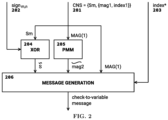
- the CNU-Generator computes the incoming messages to the VNU module using the CNM and the sign memory.
- a CNU-Generator that uses the PMM functions is referred to as PMM-CNU-Generator and implements the PMM-CNU-Step-A of Algorithm 3.
- the PMM unit 205 computes the predicted value of mag ⁇ 2 from MAG (1), using function ⁇ 1 .
- the message generation unit 206 implements the step PMM-CNU-Step-A- (c) of Table 1. At the output of unit 206, we get the check-to-variable message ⁇ c m ,v n which serves as input to the VNU.
- the PMM unit 205 is bypassed and the message generation unit 206 takes only the CNS values, the temporary extrinsic sign s ⁇ , and the processed block-column index as inputs.
- d v check-to-variable messages are sent to the VNU module to compute the variable-to-check messages ⁇ v n ,c m , that will serve as inputs to the CNU-Updater.
- the VNU update function is defined as a low precision function ⁇ v , corresponding to the FAID algorithm as described in the background.
- VNU update function ⁇ v can be defined as a closed-form function, a look-up table, an arbitrary map, a set of equations, or any other applicable finite precision update function.
- the messages are represented in n s bits of precision, and the VNU update function will be referred to as a n s -bits FAID update function, which can be applied indifferently to hard output channels, or any n q -bits soft input channel.
- the VNU module can use multiple VNU update functions ⁇ ⁇ 1 , ... , ⁇ ⁇ d for the computation of the variable-to-check messages, in order to improve the error correction performance of the decoder.
- VNU update functions can be used for different block-column processing.
- the CNU-Updater For each processed VN v n in the processed block-column, composed of d v circulants, the CNU-Updater computes new values of the CNS for the d v processed CNs connected to v n .
- a CNU-Updater that uses the PMM functions is referred to as PMM-CNU-Updater and implements the PMM-CNU-Step-B of Algorithm 3.
- the PMM-CNU-Updater described in Table 2 differs from the CNU-Updater of the classical VL decoder in steps (f) and (i).
- the PMM function ⁇ ⁇ computes an additional magnitude mag ⁇ ⁇ + 1 , which forms a additional magnitude pair together with the current block-column index: ( mag ⁇ ⁇ + 1 , index * ).
- the PMM additional pair is also considered in the sorted list before truncation, in step (i).
- FIG. 3 we show the architecture of the apparatus implementing the PMM-CNU-Updater, which updates the CNS stored in the CNM, for the general case of ⁇ magnitude states.
- the PMM-CNU-Updater takes as inputs the new variable-to-check message ⁇ v n ,c m 301 that has been generated by the VNU module, the corresponding sign sign m,n 303 from the previous iteration, and the old CNS for c m 302.
- the CNS is composed of the syndrome bit s m and ⁇ pairs ( mag k , index k ) in the magnitude state, MAG ( ⁇ ) .
- and sign* sign ( ⁇ v n ,c m ) .
- the value sign* corresponds to the new sign sign m , n new 310 to be stored in the sign memory 101.
- the updated syndrome bit s m new is obtained using a 3-input XOR unit 306 which performs an XOR operation of the old syndrome bit s m with the old sign sign m,n , and with the sign of the new input message sign*.
- the PMM unit 307 computes the value of mag ⁇ ⁇ + 1 from the magnitudes in MAG ( ⁇ ) , using the PMM function ⁇ ⁇ .
- the Magnitude State Updater proceeds as follows. First, the unit checks if the current index index* is present in the old magnitude state MAG ( ⁇ ) , and removes the corresponding pair ( mag k , index k ) . If index* does not appear in MAG ( ⁇ ) , no pair is removed. Then, we associate the current block-column index to the PMM additional magnitude to form a PMM pair mag ⁇ ⁇ + 1 , index * . The PMM pair and the newly generated pair (mag*, index*) are inserted in the sorted list to compute the new magnitude state, MAG new ( ⁇ ) .
- the sorted magnitude state MAG new ( ⁇ ) is truncated to the smallest ⁇ magnitudes, in order to form the updated magnitude state MAG new ( ⁇ ) .
- the PMM-VL decoder may also use a plurality of PMM functions in order to improve the error correction performance.
- PMM functions for a magnitude state of size ⁇ , there are d PMM functions in the set ⁇ ⁇ 1 , ... , ⁇ ⁇ d that are available to use.
- the proposed method is based on the fact that a PMM-VL decoder that uses ⁇ ⁇ k and a PMM-VL decoder that uses ⁇ ⁇ k ′ with k ⁇ k' can have different iterative decoding dynamics, and therefore yield different decoding results.
- some PMM functions could be more effective to correct the errors in the so-called waterfall region of the error rate performance of the LDPC code, while other PMM functions could be more efficient in the error floor region of the error rate performance of the LDPC code.
- Static Switching we refer to static switching as the case when the Multiple-PMM-VL decoder uses sequentially different PMM functions and re-initializes the decoding with the channel values each time the decoder switches to a new PMM function.
- the Multiple-PMM-VL starts the decoding of PMM-VL using ⁇ ⁇ 1 , for a maximum of It max 1 iterations. If the decoder has not converged to a valid codeword, then the decoding of PMM-VL is restarted with the same inputs but uses the next PMM function ⁇ ⁇ 2 , for a maximum of It max 2 iterations. When the decoder is restarted, the channel values 101 are used as inputs, going through the Initializer unit 102, therefore initializing the CNM 103 and the sign memory 106 with the same values as in the beginning of the decoding. This process is repeated until decoding is successful, or all d PMM functions have been exhausted.
- Dynamical Switching based on the block-column index and / or the iteration number we refer to dynamical switching as the case when the Multiple-PMM-VL decoder can select dynamically a particular PMM function, among the d available functions, during decoding and at each block-column processing, according to some constraint or a particular value of a decoder parameter. In dynamical switching, the decoder does not restart with a new initialization, and proceeds with the decoding only modifying the PMM function.
- the Multiple-PMM-VL switches between different PMM functions based on the iteration number and/or the index of the block-column.
- a list of D pre-determined values for the iteration numbers and for the block-column indices needs to be chosen.
- the iteration numbers are denoted ⁇ It (1) ,...,It ( D ) ⁇ , with It ( k ) ⁇ It ( k+ 1) and the block-column indices are denoted ⁇ index (1) ,...,index ( D ) ⁇ .
- Each pair of value ( It ( k ) ,index ( k ) ) is associated with a particular PMM function PMM(k).
- the architecture of the apparatus which implements the Multiple-PMM selection unit is described in FIG. 4 .
- the Multiple-PMM unit described in this figure replaces the PMM units, 205 in the PMM-CNU-Generator and 307 in the PMM-CNU-Updater.
- the magnitudes in MAG ( ⁇ ) are input in 401 and are used to generate the PMM additional magnitude 406, using one of the available PMM functions.
- the multiplexer 405 selects PMM k 404 to generate the PMM additional magnitude.
- the number of PMM functions d is allowed to be different than the number of switches D. For example, if D > d, the same PMM functions can be selected multiple times during the decoding process.
- the architecture of this embodiment of the Multiple-PMM-VL decoder is shown in FIG. 5 .
- the decoder is equipped with a syndrome weight computation unit 512 which uses, as inputs, the syndrome bits produced by the Validation unit 510.
- the value of the syndrome weight is sent to the Multiple-PMM-CNU modules 504 and 505.
- the PMM units, 205 in the PMM-CNU-Generator and 307 in the PMM-CNU-Updater, are replaced with the Multiple-PMM unit described in FIG. 6 .
- d 2 PMM functions
- the decoding starts with the first PMM function 603, and the syndrome weight S ⁇ in 602 is monitored at each block-column processing.
- the decision to switch between the two PMM functions 603 and 604 is taken by comparing the syndrome weight to a fixed, predetermined threshold ⁇ , in unit 606.
- PMM 1 When the constraint S ⁇ ⁇ ⁇ is satisfied, PMM 1 is selected, and when the constraint S ⁇ ⁇ ⁇ is satisfied, then PMM 2 is selected.
- the generalization to d > 2 PMM functions requires the use of d - 1 predetermined thresholds ⁇ ⁇ (1) ,..., ⁇ ( d -1) ⁇ .
- Multiple-PMM-VL decoder include (i) using a combination of the iteration and block-column index together with the syndrome weight for taking the decision to switch to a different PMM functions, or (ii) using a different metric than S ⁇ for switching between different PMM functions, including metrics that combine the syndrome bits and the values of the magnitudes stored in the CNSs.
- each PMM function in the set ⁇ ⁇ 1 , ... , ⁇ ⁇ d is associated to a VNU update function to form pairs of functions ⁇ ⁇ k ⁇ ⁇ k .
- the Multiple-PMM-VL decoder switches to a different PMM function, according to one of the switching strategies described previously, the new PMM function is used in the Multiple-PMM-CNU modules while the associated new VNU update function is used in the VNU module 509.
Landscapes
- Physics & Mathematics (AREA)
- Probability & Statistics with Applications (AREA)
- Engineering & Computer Science (AREA)
- Theoretical Computer Science (AREA)
- Mathematical Physics (AREA)
- Error Detection And Correction (AREA)
Claims (16)
- Verfahren zur vertikalen geschichteten Decodierung von quasi-zyklischen LDPC (Low-Density Parity-Check, niederverdichtete Paritätsprüfung), -Codes, wobei entsprechende Paritätsprüfungsmatrizen der quasi-zyklischen LDPC-Codes aus zirkulanten Permutationsmatrizen bestehen, die Blockspalten bilden, wobei das Verfahren umfasst:Empfangen von Kanalwerten, die zu einem Kanalausgangsalphabet gehören, als Eingaben;Verwenden der Kanalwerte für die Initialisierung und iterative Verarbeitung von Nachrichten zwischen Variablenknoten und Prüfknoten innerhalb von Blockspalten in beliebiger Reihenfolge und sequenziell von einer Gruppe von ein oder mehreren Blockspalten zu einer anderen Gruppe von ein oder mehreren Blockspalten;Initialisieren, während der Initialisierung, von Prüfknotenzuständen, die den Prüfknoten zugeordnet sind, durch Berechnen von Syndrombits und Magnituden der Prüfknotenzustände;Berechnen, während der Initialisierung, der jeweiligen Vorzeichen der Variablenknoten-zu-Prüfknoten-Nachrichten;Speichern der Prüfknotenzustände in einem Prüfknotenspeicher, wobei jeder Prüfknotenzustand einem Prüfknoten zugeordnet ist, der ein Syndrombit, das aus den Vorzeichen der Variablenknoten-zu-Prüfknoten-Nachrichten des zugeordneten Prüfknotens berechnet wird, und einen Satz von Werten, der eine oder mehrere kleinste Magnituden der Variablenknoten-zu-Prüfknoten-Nachrichten des zugeordneten Prüfknotens umfasst, zusammen mit einer gleichen Anzahl von jeweiligen Blockspaltenindizes umfasst;iteratives Verarbeiten einer Gruppe der ein oder mehreren Blockspalten, wobei die iterative Verarbeitung umfasst:Berechnen neuer Prüfknoten-zu-Variablenknoten-Nachrichten mit Eingängen, die die Prüfknotenzustände und die Vorzeichen der Variablenknoten-zu-Prüfknoten-Nachrichten als Eingaben umfassen, wobei für jeden Prüfknoten die Berechnung unter Verwendung eines CNU (Check Node Update, Prüfknotenaktualisierungs) - Erzeuger-Schritts durchgeführt wird, der die ein oder mehreren kleinsten Magnituden des zugeordneten Prüfknotenzustands und eine oder mehrere zusätzliche Magnituden verwendet, die aus den ein oder mehreren kleinsten Magnituden des zugeordneten Prüfknotenzustands erzeugt werden, indem eine oder mehrere prädiktive Magnitudenkarten verwendet werden, wobei eine prädiktive Magnitudenkarte eine Funktion ist, die die ein oder mehreren kleinsten Magnituden des zugeordneten Prüfknotenzustands auf eine zusätzliche Magnitude abbildet;Berechnen neuer Variablenknoten-zu-Prüfknoten-Nachrichten mit Eingaben, die die Kanalwerte und die Prüfknoten-zu-Variablenknoten-Nachrichten umfassen, unter Verwendung einer oder mehrerer Variablenknoten-Aktualisierungsfunktionen; undAktualisieren der Prüfknotenzustände auf neue Werte mit Eingaben, die die Variablenknoten-zu-Prüfknoten-Nachrichten umfassen, wobei für jeden Prüfknotenzustand die Aktualisierung unter Verwendung eines CNU (Check Node Update) -Aktualisierer-Schritts durchgeführt wird, der die ein oder mehreren kleinsten Magnituden des zugeordneten Prüfknotenzustands und eine oder mehrere zusätzliche Magnituden verwendet, die aus den ein oder mehreren kleinsten Magnituden des zugeordneten Prüfknotenzustands unter Verwendung einer oder mehrerer prädiktiver Magnitudenkarten erzeugt werden;Berechnen der Syndrombits aus den Hard-Decision (harte Entscheidung) -Schätzungen und Überprüfen, ob die Hard-Decision-Schätzungen ein Codewort darstellen; undAusgeben des Codeworts gemäß den Hard-Decision-Schätzungen, die ein Codewort darstellen.
- Verfahren nach Anspruch 1, wobei:jeder Prüfknotenzustand, der einem Prüfknoten zugeordnet ist, das Syndrombit, das aus den Vorzeichen der Variablenknoten-zu-Prüfknoten-Nachrichten des zugeordneten Prüfknotens berechnet wird, und einen Satz von zwei kleinsten Magnituden der Variablenknoten-zu-Prüfknoten-Nachrichten des zugeordneten Prüfknotens umfasst, zusammen mit deren beiden jeweiligen Blockspaltenindizes; undwährend des CNU-Aktualisierer-Schritts an jedem Prüfknoten der zugeordnete Prüfknotenzustand unter Verwendung der beiden Magnituden des zugeordneten Prüfknotenzustands und einer dritten Magnitude, die aus den beiden Magnituden des zugeordneten Prüfknotenzustands unter Verwendung einer prädiktiven Magnitudenkarte erzeugt wird, aktualisiert wird.
- Verfahren nach Anspruch 1, wobei:jeder Prüfknotenzustand, der einem Prüfknoten zugeordnet ist, das Syndrombit, das aus den Vorzeichen der Variablenknoten-zu-Prüfknoten-Nachrichten des zugeordneten Prüfknotens berechnet wird, und eine einzelne kleinste Magnitude der Variablenknoten-zu-Prüfknoten-Nachrichten des zugeordneten Prüfknotens umfasst, zusammen mit ihrem jeweiligen Blockspaltenindex;während des CNU-Aktualisierer-Schritts an jedem Prüfknoten der zugeordnete Prüfknotenzustand unter Verwendung der einzelnen Magnitude des zugeordneten Prüfknotenzustands und einer zweiten Magnitude, die aus der einzelnen Magnitude des zugeordneten Prüfknotenzustands unter Verwendung einer prädiktiven Magnitudenkarte erzeugt wird, aktualisiert wird; undwährend des CNU-Erzeuger-Schritts an jedem Prüfknoten die neuen Prüfknoten-zu-Variablenknoten-Nachrichten unter Verwendung der einzelnen Magnitude des zugeordneten Prüfknotenzustands und einer zweiten Magnitude, die aus der Magnitude des zugeordneten Prüfknotenzustands unter Verwendung einer prädiktiven Magnitudenkarte erzeugt wird, berechnet werden.
- Verfahren nach Anspruch 1, wobei:die iterative Verarbeitung sequentiell in beliebiger Reihenfolge von einer Blockspalte zu einer anderen Blockspalte durchgeführt wird;jeder Prüfknotenzustand, der einem Prüfknoten zugeordnet ist, das Syndrombit, das aus den Vorzeichen der Variablenknoten-zu-Prüfknoten-Nachrichten des zugeordneten Prüfknotens berechnet wird, und einen Satz von zwei kleinsten Magnituden der Variablenknoten-zu-Prüfknoten-Nachrichten des zugeordneten Prüfknotens umfasst, zusammen mit deren beiden jeweiligen Blockspaltenindizes;während des CNU-Aktualisierer-Schritts an jedem Prüfknoten der zugeordnete Prüfknotenzustand unter Verwendung der beiden Magnituden des zugeordneten Prüfknotenzustands und einer dritten Magnitude, die aus einer Mehrzahl von Magnituden ausgewählt wird, die aus den beiden Magnituden des zugeordneten Prüfknotenzustands unter Verwendung einer Mehrzahl von prädiktiven Magnitudenkarten erzeugt werden, aktualisiert wird; unddie dritte Magnitude aus einer Mehrzahl von Magnituden zur Verwendung im CNU-Aktualisierer-Schritt basierend auf dem Index der Blockspalte, die verarbeitet wird, ausgewählt wird.
- Verfahren nach Anspruch 1, ferner umfassend das Berechnen des Syndromgewichts während der iterativen Verarbeitung jeder Gruppe von ein oder mehreren Blockspalten, und wobei:jeder Prüfknotenzustand, der einem Prüfknoten zugeordnet ist, das Syndrombit, das aus den Vorzeichen der Variablenknoten-zu-Prüfknoten-Nachrichten des zugeordneten Prüfknotens berechnet wird, und einen Satz von zwei kleinsten Magnituden der Variablenknoten-zu-Prüfknoten-Nachrichten des zugeordneten Prüfknotens umfasst, zusammen mit deren beiden jeweiligen Blockspaltenindizes;während des CNU-Aktualisierer-Schritts an jedem Prüfknoten der zugeordnete Prüfknotenzustand unter Verwendung der beiden Magnituden des zugeordneten Prüfknotenzustands und einer dritten Magnitude, die aus einer Mehrzahl von Magnituden ausgewählt wird, die aus den beiden Magnituden des zugeordneten Prüfknotenzustands unter Verwendung einer Mehrzahl von prädiktiven Magnitudenkarten erzeugt werden, aktualisiert wird; unddie dritte Magnitude aus einer Mehrzahl von Magnituden zur Verwendung im CNU-Aktualisierer-Schritt basierend auf dem Wert des Syndromgewichts ausgewählt wird.
- Verfahren nach Anspruch 1, wobei:jeder Prüfknotenzustand, der einem Prüfknoten zugeordnet ist, das Syndrombit, das aus den Vorzeichen der Variablenknoten-zu-Prüfknoten-Nachrichten des zugeordneten Prüfknotens berechnet wird, und einen Satz von zwei kleinsten Magnituden der Variablenknoten-zu-Prüfknoten-Nachrichten des zugeordneten Prüfknotens umfasst, zusammen mit deren beiden jeweiligen Blockspaltenindizes;während des CNU-Aktualisierer-Schritts an einem Prüfknoten der zugeordnete Prüfknotenzustand unter Verwendung der beiden Magnituden des zugeordneten Prüfknotenzustands und einer dritten Magnitude, die aus einer Mehrzahl von Magnituden ausgewählt wird, die aus den beiden Magnituden des zugeordneten Prüfknotenzustands unter Verwendung einer Mehrzahl von prädiktiven Magnitudenkarten erzeugt werden, aktualisiert wird; undeine dritte Magnitude aus einer Mehrzahl von Magnituden zur Verwendung im CNU-Aktualisierer-Schritt an einem Prüfknoten während der Verarbeitung einer Gruppe von ein oder mehreren Blockspalten ausgewählt wird und eine andere dritte Magnitude aus der Mehrzahl von Magnituden zur Verwendung im CNU-Aktualisierer-Schritt während der Verarbeitung einer anderen Gruppe von ein oder mehreren Blockspalten ausgewählt wird.
- Verfahren nach Anspruch 1, wobei:die iterative Verarbeitung sequentiell in beliebiger Reihenfolge von einer Blockspalte zu einer anderen Blockspalte durchgeführt wird;jeder Prüfknotenzustand, der einem Prüfknoten zugeordnet ist, das Syndrombit, das aus den Vorzeichen der Variablenknoten-zu-Prüfknoten-Nachrichten des zugeordneten Prüfknotens berechnet wird, und eine einzelne kleinste Magnitude der Variablenknoten-zu-Prüfknoten-Nachrichten des zugeordneten Prüfknotens umfasst, zusammen mit ihrem jeweiligen Blockspaltenindex;während des CNU-Aktualisierer-Schritts an einem Prüfknoten der zugeordnete Prüfknotenzustand unter Verwendung der einzelnen Magnitude des zugeordneten Prüfknotenzustands und einer zweiten Magnitude, die aus einer Mehrzahl von Magnituden ausgewählt wird, die aus der einzelnen Magnitude des zugeordneten Prüfknotenzustands unter Verwendung einer Mehrzahl von prädiktiven Magnitudenkarten erzeugt werden, aktualisiert wird;die zweite Magnitude aus einer Mehrzahl von Magnituden zur Verwendung im CNU-Aktualisierer-Schritt basierend auf dem Index der Blockspalte, die verarbeitet wird, ausgewählt wird;während des CNU-Erzeuger-Schritts an einem Prüfknoten die neuen Prüfknoten-zu-Variablenknoten-Nachrichten unter Verwendung der einzelnen Magnitude des zugeordneten Prüfknotenzustands und einer zweiten Magnitude, die aus einer Mehrzahl von Magnituden ausgewählt wird, die aus der einzelnen Magnitude des zugeordneten Prüfknotenzustands unter Verwendung einer Mehrzahl von prädiktiven Magnitudenkarten erzeugt werden, berechnet werden; unddie zweite Magnitude aus einer Mehrzahl von Magnituden zur Verwendung im CNU-Erzeuger-Schritt basierend auf dem Index der Blockspalte, die verarbeitet wird, ausgewählt wird.
- Verfahren nach Anspruch 1, ferner umfassend das Berechnen des Syndromgewichts während der iterativen Verarbeitung jeder Gruppe von ein oder mehreren Blockspalten, und wobei:jeder Prüfknotenzustand, der einem Prüfknoten zugeordnet ist, das Syndrombit, das aus den Vorzeichen der Variablenknoten-zu-Prüfknoten-Nachrichten des zugeordneten Prüfknotens berechnet wird, und eine einzelne kleinste Magnitude der Variablenknoten-zu-Prüfknoten-Nachrichten des zugeordneten Prüfknotens umfasst, zusammen mit ihrem jeweiligen Blockspaltenindex;während des CNU-Aktualisierer-Schritts an einem Prüfknoten der zugeordnete Prüfknotenzustand unter Verwendung der einzelnen Magnitude des zugeordneten Prüfknotenzustands und einer zweiten Magnitude, die aus einer Mehrzahl von Magnituden ausgewählt wird, die aus der einzelnen Magnitude des zugeordneten Prüfknotenzustands unter Verwendung einer Mehrzahl von prädiktiven Magnitudenkarten erzeugt werden, aktualisiert wird;die zweite Magnitude aus einer Mehrzahl von Magnituden zur Verwendung im CNU-Aktualisierer-Schritt basierend auf dem Syndromgewicht ausgewählt wird;während des CNU-Erzeuger-Schritts an einem Prüfknoten die neuen Prüfknoten-zu-Variablenknoten-Nachrichten unter Verwendung der einzelnen Magnitude des zugeordneten Prüfknotenzustands und einer zweiten Magnitude, die aus einer Mehrzahl von Magnituden ausgewählt wird, die aus der einzelnen Magnitude des zugeordneten Prüfknotenzustands unter Verwendung einer Mehrzahl von prädiktiven Magnitudenkarten erzeugt werden, berechnet werden; unddie zweite Magnitude aus einer Mehrzahl von Magnituden zur Verwendung im CNU-Erzeuger-Schritt basierend auf dem Wert des Syndromgewichts ausgewählt wird.
- Verfahren nach Anspruch 1, wobei:jeder Prüfknotenzustand, der einem Prüfknoten zugeordnet ist, das Syndrombit, das aus den Vorzeichen der Variablenknoten-zu-Prüfknoten-Nachrichten des zugeordneten Prüfknotens berechnet wird, und eine einzelne kleinste Magnitude der Variablenknoten-zu-Prüfknoten-Nachrichten des zugeordneten Prüfknotens umfasst, zusammen mit ihrem jeweiligen Blockspaltenindex;während des CNU-Aktualisierer-Schritts an einem Prüfknoten der zugeordnete Prüfknotenzustand unter Verwendung der einzelnen Magnitude des zugeordneten Prüfknotenzustands und einer zweiten Magnitude, die aus einer Mehrzahl von Magnituden ausgewählt wird, die aus der einzelnen Magnitude des zugeordneten Prüfknotenzustands unter Verwendung einer Mehrzahl von prädiktiven Magnitudenkarten erzeugt werden, aktualisiert wird;eine zweite Magnitude aus einer Mehrzahl von Magnituden zur Verwendung im CNU-Aktualisierer-Schritt an einem Prüfknoten während der Verarbeitung einer Gruppe von ein oder mehreren Blockspalten ausgewählt wird und eine andere zweite Magnitude aus der Mehrzahl von Magnituden zur Verwendung im CNU-Aktualisierer-Schritt während der Verarbeitung einer anderen Gruppe von ein oder mehreren Blockspalten ausgewählt wird;während des CNU-Erzeuger-Schritts an einem Prüfknoten die neuen Prüfknoten-zu-Variablenknoten-Nachrichten unter Verwendung der einzelnen Magnitude des zugeordneten Prüfknotenzustands und einer zweiten Magnitude, die aus einer Mehrzahl von Magnituden ausgewählt wird, die aus der einzelnen Magnitude des zugeordneten Prüfknotenzustands unter Verwendung einer Mehrzahl von prädiktiven Magnitudenkarten erzeugt werden, berechnet werden; undeine zweite Magnitude aus einer Mehrzahl von Magnituden zur Verwendung im CNU-Erzeuger-Schritt an einem Prüfknoten während der Verarbeitung einer Gruppe von ein oder mehreren Blockspalten ausgewählt wird und eine andere zweite Magnitude aus der Mehrzahl von Magnituden zur Verwendung im CNU-Erzeuger-Schritt während der Verarbeitung einer anderen Gruppe von ein oder mehreren Blockspalten ausgewählt wird.
- Verfahren nach Anspruch 1, ferner umfassend das Berechnen des Syndromgewichts während der iterativen Verarbeitung jeder Gruppe von ein oder mehreren Blockspalten, und wobei:jeder Prüfknotenzustand, der einem Prüfknoten zugeordnet ist, das Syndrombit, das aus den Vorzeichen der Variablenknoten-zu-Prüfknoten-Nachrichten des zugeordneten Prüfknotens berechnet wird, und einen Satz von zwei kleinsten Magnituden der Variablenknoten-zu-Prüfknoten-Nachrichten des zugeordneten Prüfknotens umfasst, zusammen mit deren beiden jeweiligen Blockspaltenindizes;während des CNU-Aktualisierer-Schritts an einem Prüfknoten der zugeordnete Prüfknotenzustand unter Verwendung der beiden Magnituden des zugeordneten Prüfknotenzustands und einer dritten Magnitude, die aus zwei Werten ausgewählt wird, die aus den beiden Magnituden des zugeordneten Prüfknotenzustands unter Verwendung von zwei verschiedenen prädiktiven Magnitudenkarten erzeugt werden, aktualisiert wird; undder erste Wert der beiden Werte als die dritte Magnitude zur Verwendung im CNU-Aktualisierer-Schritt ausgewählt wird, wenn das Syndromgewicht größer als ein vorbestimmter Schwellenwert ist, und der zweite Wert der beiden Werte als die dritte Magnitude zur Verwendung im CNU-Aktualisierer-Schritt ausgewählt wird, wenn das Syndromgewicht kleiner oder gleich dem vorbestimmten Schwellenwert ist.
- Verfahren nach Anspruch 1, ferner umfassend das Berechnen des Syndromgewichts während der iterativen Verarbeitung jeder Gruppe von ein oder mehreren Blockspalten, und wobei:jeder Prüfknotenzustand, der einem Prüfknoten zugeordnet ist, das Syndrombit, das aus den Vorzeichen der Variablenknoten-zu-Prüfknoten-Nachrichten des zugeordneten Prüfknotens berechnet wird, und eine einzelne kleinste Magnitude der Variablenknoten-zu-Prüfknoten-Nachrichten des zugeordneten Prüfknotens umfasst, zusammen mit ihrem jeweiligen Blockspaltenindex;während des CNU-Aktualisierer-Schritts an einem Prüfknoten der zugeordnete Prüfknotenzustand unter Verwendung der einzelnen Magnitude des zugeordneten Prüfknotenzustands und einer zweiten Magnitude, die aus zwei Werten ausgewählt wird, die aus der einzelnen Magnitude des zugeordneten Prüfknotenzustands unter Verwendung von zwei verschiedenen prädiktiven Magnitudenkarten erzeugt werden, aktualisiert wird;der erste Wert der beiden Werte als die zweite Magnitude zur Verwendung im CNU-Aktualisierer-Schritt ausgewählt wird, wenn das Syndromgewicht größer als ein vorbestimmter Schwellenwert ist, und der zweite Wert der beiden Werte als die zweite Magnitude zur Verwendung im CNU-Aktualisierer-Schritt ausgewählt wird, wenn das Syndromgewicht kleiner oder gleich dem vorbestimmten Schwellenwert ist;während des CNU-Erzeuger-Schritts an einem Prüfknoten die neuen Prüfknoten-zu-Variablenknoten-Nachrichten unter Verwendung der einzelnen Magnitude des zugeordneten Prüfknotenzustands und einer zweiten Magnitude, die aus zwei Werten ausgewählt wird, die aus der einzelnen Magnitude des zugeordneten Prüfknotenzustands unter Verwendung von zwei verschiedenen prädiktiven Magnitudenkarten erzeugt werden, berechnet werden; undder erste Wert der beiden Werte als die zweite Magnitude zur Verwendung im CNU-Erzeuger-Schritt ausgewählt wird, wenn das Syndromgewicht größer als ein vorbestimmter Schwellenwert ist, und der zweite Wert der beiden Werte als die zweite Magnitude zur Verwendung im CNU-Erzeuger-Schritt ausgewählt wird, wenn das Syndromgewicht kleiner oder gleich dem vorbestimmten Schwellenwert ist.
- Verfahren nach Anspruch 1, wobei:jeder Prüfknotenzustand, der einem Prüfknoten zugeordnet ist, das Syndrombit, das aus den Vorzeichen der Variablenknoten-zu-Prüfknoten-Nachrichten des zugeordneten Prüfknotens berechnet wird, und einen Satz von kleinsten Magnituden der Variablenknoten-zu-Prüfknoten-Nachrichten des zugeordneten Prüfknotens umfasst, zusammen mit deren jeweiligen Blockspaltenindizes;eine prädiktive Magnitudenkarte aus einer Mehrzahl von prädiktiven Magnitudenkarten ausgewählt wird, um eine oder mehrere Magnituden aus den Magnituden jedes Prüfknotenzustands für die Berechnung der neuen Prüfknoten-zu-Variablenknoten-Nachrichten während des CNU-Erzeuger-Schritts zu erzeugen;eine Variablenknoten-Aktualisierungsfunktion aus einer Mehrzahl von Variablenknoten-Aktualisierungsfunktionen ausgewählt wird, um die neuen Variablenknoten-zu-Prüfknoten-Nachrichten an jedem Variablenknoten unter Verwendung des Kanalwerts und der Prüfknoten-zu-Variablenknoten-Nachrichten des zugeordneten Variablenknotens als Eingaben zu berechnen; unddie Variablenknoten-Aktualisierungsfunktion basierend auf der prädiktiven Magnitudenkarte, die während des CNU-Erzeuger-Schritts an jedem Prüfknoten verwendet wird, ausgewählt wird.
- Einrichtung zur vertikalen geschichteten Decodierung von quasi-zyklischen LDPC (Low-Density Parity-Check, niederverdichtete Paritätsprüfung), - Codes, wobei entsprechende Paritätsprüfungsmatrizen der quasi-zyklischen LDPC-Codes aus zirkulanten Permutationsmatrizen bestehen, die Blockspalten bilden, wobei die Einrichtung umfasst:eine Initialisierungseinheit (102), die Kanalwerte (101), die zu einem Kanalausgangssalphabet gehören, als Eingaben erhält und sie verwendet, um Prüfknotenzustände zu initialisieren, die Prüfknoten zugeordnet sind;einen Prüfknotenspeicher (103), der die Prüfknotenzustände enthält, die Prüfknoten zugeordnet sind, wobei jeder Prüfknotenzustand, der einem Prüfknoten zugeordnet ist, ein Syndrombit, das aus den Vorzeichen von Variablenknoten-zu-Prüfknoten-Nachrichten des zugeordneten Prüfknotens berechnet wird, und einen Satz von Werten, der eine oder mehrere kleinste Magnituden der Variablenknoten-zu-Prüfknoten-Nachrichten des zugeordneten Prüfknotens umfasst, zusammen mit einer gleichen Anzahl von jeweiligen Blockspaltenindizes umfasst;eine PMM-CNU (Predictive Magnitude Map Check Node Update-Generator, prädiktive Magnitudenkarte Prüfknotenaktualisierungs-Erzeuger) - Verarbeitungseinheit (105), die neue Prüfknoten-zu-Variablenknoten-Nachrichten mit Eingängen berechnet, die die Prüfknotenzustände und die Vorzeichen der Variablenknoten-zu-Prüfknoten-Nachrichten als Eingaben umfassen, wobei für jeden Prüfknoten die Berechnung unter Verwendung der ein oder mehreren kleinsten Magnituden des zugeordneten Prüfknotenzustands und eine oder mehrere zusätzliche Magnituden, die aus den ein oder mehreren kleinsten Magnituden des zugeordneten Prüfknotenzustands erzeugt werden, durchgeführt wird, indem eine oder mehrere prädiktive Magnitudenkarten verwendet werden, wobei eine prädiktive Magnitudenkarte eine Funktion ist, die die ein oder mehreren kleinsten Magnituden des zugeordneten Prüfknotenzustands auf eine zusätzliche Magnitude abbildet;ein Variablenknoten-Aktualisierungsmodul (109), das die Kanalwerte und die Prüfknoten-zu-Variablenknoten-Nachrichten als Eingaben empfängt und neue Variablenknoten-zu-Prüfknoten-Nachrichten unter Verwendung einer oder mehrerer Variablenknoten-Aktualisierungsfunktionen berechnet; undeine PMM-CNU (Predictive Magnitude Map Check Node Update-Updater, prädiktive Magnitudenkarte Prüfknotenaktualisierungs-Aktualisierer) - Verarbeitungseinheit (104), die die Prüfknotenzustände auf neue Werte mit Eingaben, die die Variablenknoten-zu-Prüfknoten-Nachrichten umfassen, aktualisiert, wobei für jeden Prüfknoten die Aktualisierung unter Verwendung der ein oder mehreren kleinsten Magnituden des zugeordneten Prüfknotenzustands und einer oder mehrerer zusätzlicher Magnituden durchgeführt wird, die aus den ein oder mehreren kleinsten Magnituden des zugeordneten Prüfknotenzustands unter Verwendung einer oder mehrerer prädiktiver Magnitudenkarten erzeugt werden.
- Einrichtung nach Anspruch 13, wobei:jeder Prüfknotenzustand, der einem Prüfknoten zugeordnet ist, das Syndrombit, das aus den Vorzeichen der Variablenknoten-zu-Prüfknoten-Nachrichten des zugeordneten Prüfknotens berechnet wird, und einen Satz von zwei kleinsten Magnituden der Variablenknoten-zu-Prüfknoten-Nachrichten des zugeordneten Prüfknotens umfasst, zusammen mit deren beiden jeweiligen Blockspaltenindizes; unddie PMM-CNU-Aktualisierer-Verarbeitungseinheit den Prüfknotenzustand jedes Prüfknotens unter Verwendung der beiden Magnituden des zugeordneten Prüfknotenzustands und einer dritten Magnitude, die aus einer Mehrzahl von Magnituden ausgewählt wird, die aus den beiden Magnituden des zugeordneten Prüfknotenzustands unter Verwendung einer Mehrzahl von prädiktiven Magnitudenkarten erzeugt werden, aktualisiert.
- Einrichtung nach Anspruch 13, wobei:jeder Prüfknotenzustand, der einem Prüfknoten zugeordnet ist, das Syndrombit, das aus den Vorzeichen der Variablenknoten-zu-Prüfknoten-Nachrichten des zugeordneten Prüfknotens berechnet wird, und eine einzelne kleinste Magnitude der Variablenknoten-zu-Prüfknoten-Nachrichten des zugeordneten Prüfknotens umfasst, zusammen mit ihrem jeweiligen Blockspaltenindex;die PMM-CNU-Erzeuger-Verarbeitungseinheit die neuen Prüfknoten-zu-Variablenknoten-Nachrichten an jedem Prüfknoten unter Verwendung der einzelnen Magnitude des zugeordneten Prüfknotenzustands und einer zweiten Magnitude, die aus einer Mehrzahl von Magnituden ausgewählt wird, die aus der einzelnen Magnitude des zugeordneten Prüfknotenzustands unter Verwendung einer Mehrzahl von prädiktiven Magnitudenkarten erzeugt werden, berechnet; unddie PMM-CNU-Aktualisierer-Verarbeitungseinheit den Prüfknotenzustand jedes Prüfknotens unter Verwendung der einzelnen Magnitude des zugeordneten Prüfknotenzustands und einer zweiten Magnitude, die aus einer Mehrzahl von Magnituden ausgewählt wird, die aus der einzelnen Magnitude des zugeordneten Prüfknotenzustands unter Verwendung einer Mehrzahl von prädiktiven Magnitudenkarten erzeugt werden, aktualisiert.
- Einrichtung nach Anspruch 13, wobei das Variablenknoten-Aktualisierungsmodul eine Mehrzahl von Variablenknoten-Aktualisierungsfunktionen verwendet und wobei:jeder Prüfknotenzustand, der einem Prüfknoten zugeordnet ist, das Syndrombit, das aus den Vorzeichen der Variablenknoten-zu-Prüfknoten-Nachrichten des zugeordneten Prüfknotens berechnet wird, und einen Satz von kleinsten Magnituden der Variablenknoten-zu-Prüfknoten-Nachrichten des zugeordneten Prüfknotens umfasst, zusammen mit deren jeweiligen Blockspaltenindizes;die PMM-CNU-Erzeuger-Verarbeitungseinheit eine prädiktive Magnitudenkarte aus einer Mehrzahl von prädiktiven Magnitudenkarten auswählt, um eine oder mehrere Magnituden aus den Magnituden jedes Prüfknotenzustands für die Berechnung der neuen Prüfknoten-zu-Variablenknoten-Nachrichten an jedem Prüfknoten zu erzeugen;das Variablenknoten-Aktualisierungsmodul eine Variablenknoten-Aktualisierungsfunktion aus einer Mehrzahl von Variablenknoten-Aktualisierungsfunktionen auswählt, um die neuen Variablenknoten-zu-Prüfknoten-Nachrichten an jedem Variablenknoten unter Verwendung des Kanalwerts und der Prüfknoten-zu-Variablenknoten-Nachrichten des zugeordneten Variablenknotens als Eingaben zu berechnen; unddas Variablenknoten-Aktualisierungsmodul die Variablenknoten-Aktualisierungsfunktion basierend auf der prädiktiven Magnitudenkarte auswählt, die an jedem Prüfknoten von der PMM-CNU-Erzeuger-Verarbeitungseinheit verwendet wird.
Applications Claiming Priority (2)
| Application Number | Priority Date | Filing Date | Title |
|---|---|---|---|
| US202063007841P | 2020-04-09 | 2020-04-09 | |
| US17/224,064 US11496155B2 (en) | 2020-04-09 | 2021-04-06 | Method and apparatus for vertical layered decoding of quasi-cyclic low-density parity check codes using predictive magnitude maps |
Publications (2)
| Publication Number | Publication Date |
|---|---|
| EP3893399A1 EP3893399A1 (de) | 2021-10-13 |
| EP3893399B1 true EP3893399B1 (de) | 2025-05-28 |
Family
ID=75441726
Family Applications (1)
| Application Number | Title | Priority Date | Filing Date |
|---|---|---|---|
| EP21167522.8A Active EP3893399B1 (de) | 2020-04-09 | 2021-04-08 | Verfahren und vorrichtung zur vertikalen geschichteten decodierung von quasi-cyclischen low-density-parity-check-codes mit vereinfachter prüfknotenverarbeitung |
Country Status (3)
| Country | Link |
|---|---|
| EP (1) | EP3893399B1 (de) |
| CN (1) | CN113517895A (de) |
| TW (1) | TWI911208B (de) |
Families Citing this family (3)
| Publication number | Priority date | Publication date | Assignee | Title |
|---|---|---|---|---|
| CN115913250B (zh) * | 2022-10-24 | 2026-01-06 | 东南大学 | 适用于5g ldpc码的有限精度量化分层非满射有限字符集译码方法 |
| CN115801022B (zh) * | 2022-11-18 | 2025-07-08 | 成都中科微信息技术研究院有限公司 | 一种低复杂度的适用于nr标准的ldpc译码方法、介质及装置 |
| EP4456436B1 (de) | 2023-04-24 | 2025-12-24 | Samsung Electronics Co., Ltd. | Fehlerkorrekturcodeschaltung mit low-density-parity-check-decodierer im adaptiven betriebsmodus, betriebsverfahren der ecc-schaltung und speichersteuergerät mit der ecc-schaltung |
Family Cites Families (8)
| Publication number | Priority date | Publication date | Assignee | Title |
|---|---|---|---|---|
| CN101534166B (zh) * | 2008-03-10 | 2012-07-11 | 上海明波通信技术有限公司 | 准循环低密度奇偶校验码解码器及解码方法 |
| EP2464019A1 (de) * | 2010-12-09 | 2012-06-13 | Nxp B.V. | Decodierung von Low-Density-Parity-Check (LDPC) -Codes |
| US8819515B2 (en) * | 2011-12-30 | 2014-08-26 | Lsi Corporation | Mixed domain FFT-based non-binary LDPC decoder |
| EP3264610A1 (de) * | 2016-06-27 | 2018-01-03 | Alcatel Lucent | Vorwärtsfehlerkorrektur mit veränderlicher codierungsrate |
| US10567116B2 (en) * | 2017-05-12 | 2020-02-18 | Mediatek Inc. | Wireless communication using codebooks from a QC-LDPC code for shorter processing latency and improved decoder throughput efficiency |
| US10530392B2 (en) * | 2017-07-31 | 2020-01-07 | Codelucida, Inc. | Vertical layered finite alphabet iterative decoding |
| KR102706725B1 (ko) * | 2018-07-03 | 2024-09-19 | 에스케이하이닉스 주식회사 | 메모리 컨트롤러 및 이의 동작 방법 |
| US10715178B2 (en) * | 2018-09-25 | 2020-07-14 | Western Digital Technologies, Inc. | Generalized low-density parity-check codes |
-
2021
- 2021-04-08 EP EP21167522.8A patent/EP3893399B1/de active Active
- 2021-04-09 CN CN202110385012.0A patent/CN113517895A/zh active Pending
- 2021-04-09 TW TW110112899A patent/TWI911208B/zh active
Also Published As
| Publication number | Publication date |
|---|---|
| TWI911208B (zh) | 2026-01-11 |
| CN113517895A (zh) | 2021-10-19 |
| EP3893399A1 (de) | 2021-10-13 |
| TW202203238A (zh) | 2022-01-16 |
Similar Documents
| Publication | Publication Date | Title |
|---|---|---|
| US11381255B2 (en) | Vertical layered finite alphabet iterative decoding | |
| US11496155B2 (en) | Method and apparatus for vertical layered decoding of quasi-cyclic low-density parity check codes using predictive magnitude maps | |
| EP4231532B1 (de) | Codierverfahren und -vorrichtung sowie decodierungsverfahren und -vorrichtung für strukturierten ldpc | |
| US7395494B2 (en) | Apparatus for encoding and decoding of low-density parity-check codes, and method thereof | |
| US8347170B2 (en) | Method and apparatus for performing decoding using LDPC code | |
| US8261170B2 (en) | Multi-stage decoder for error-correcting codes | |
| CN101159436B (zh) | 解码设备及方法 | |
| JP4563454B2 (ja) | 検査行列生成方法、符号化方法、復号方法、通信装置、通信システム、符号化器および復号器 | |
| US8713397B2 (en) | Apparatus and method for layered decoding in a communication system using low-density parity-check codes | |
| US11258460B2 (en) | Method and apparatus for vertical layered decoding of quasi-cyclic low-density parity check codes built from clusters of circulant permutation matrices | |
| EP3893399A1 (de) | Verfahren und vorrichtung zur vertikalen geschichteten decodierung von quasi-cyclischen low-density-parity-check-codes mit vereinfachter prüfknotenverarbeitung | |
| US7607075B2 (en) | Method and apparatus for encoding and decoding data | |
| JP2009503996A (ja) | Ldpc符号のブロックおよびレートに独立な復号の方法および装置 | |
| Zhang et al. | On bit-level decoding of nonbinary LDPC codes | |
| US8190977B2 (en) | Decoder of error correction codes | |
| Chen et al. | Nonbinary LDPC codes constructed based on a cyclic MDS code and a low-complexity nonbinary message-passing decoding algorithm | |
| JP4832447B2 (ja) | チャネルコードを用いた復号化装置及び方法 | |
| El Hassani et al. | A comparison study of binary and non-binary LDPC codes decoding | |
| KR102635444B1 (ko) | 비이진 저밀도 패리티 검사 코드 디코더, 그것의 동작방법 및 메모리 시스템 | |
| Pignoly et al. | High speed LDPC decoding for optical space link | |
| Soltanpur et al. | Lowering error floors by concatenation of low-density parity-check and array code | |
| Wu et al. | Decoding scheduling for unequal error protection quasi-cyclic low-density parity-check codes | |
| Zhou et al. | Efficient symbol reliability based decoding for QCNB-LDPC codes | |
| Baldi | Low-Density Parity-Check Codes | |
| Soltanpur et al. | Lowering Error Floors by Concatenation of Low-Density Parity-Check (LDPC) and Array Code |
Legal Events
| Date | Code | Title | Description |
|---|---|---|---|
| PUAI | Public reference made under article 153(3) epc to a published international application that has entered the european phase |
Free format text: ORIGINAL CODE: 0009012 |
|
| STAA | Information on the status of an ep patent application or granted ep patent |
Free format text: STATUS: REQUEST FOR EXAMINATION WAS MADE |
|
| 17P | Request for examination filed |
Effective date: 20210408 |
|
| AK | Designated contracting states |
Kind code of ref document: A1 Designated state(s): AL AT BE BG CH CY CZ DE DK EE ES FI FR GB GR HR HU IE IS IT LI LT LU LV MC MK MT NL NO PL PT RO RS SE SI SK SM TR |
|
| STAA | Information on the status of an ep patent application or granted ep patent |
Free format text: STATUS: EXAMINATION IS IN PROGRESS |
|
| 17Q | First examination report despatched |
Effective date: 20230428 |
|
| GRAP | Despatch of communication of intention to grant a patent |
Free format text: ORIGINAL CODE: EPIDOSNIGR1 |
|
| STAA | Information on the status of an ep patent application or granted ep patent |
Free format text: STATUS: GRANT OF PATENT IS INTENDED |
|
| INTG | Intention to grant announced |
Effective date: 20241223 |
|
| GRAS | Grant fee paid |
Free format text: ORIGINAL CODE: EPIDOSNIGR3 |
|
| GRAA | (expected) grant |
Free format text: ORIGINAL CODE: 0009210 |
|
| STAA | Information on the status of an ep patent application or granted ep patent |
Free format text: STATUS: THE PATENT HAS BEEN GRANTED |
|
| AK | Designated contracting states |
Kind code of ref document: B1 Designated state(s): AL AT BE BG CH CY CZ DE DK EE ES FI FR GB GR HR HU IE IS IT LI LT LU LV MC MK MT NL NO PL PT RO RS SE SI SK SM TR |
|
| REG | Reference to a national code |
Ref country code: GB Ref legal event code: FG4D |
|
| REG | Reference to a national code |
Ref country code: CH Ref legal event code: EP |
|
| REG | Reference to a national code |
Ref country code: IE Ref legal event code: FG4D Ref country code: DE Ref legal event code: R096 Ref document number: 602021031347 Country of ref document: DE |
|
| P01 | Opt-out of the competence of the unified patent court (upc) registered |
Free format text: CASE NUMBER: APP_31778/2025 Effective date: 20250701 |
|
| REG | Reference to a national code |
Ref country code: NL Ref legal event code: MP Effective date: 20250528 |
|
| PG25 | Lapsed in a contracting state [announced via postgrant information from national office to epo] |
Ref country code: FI Free format text: LAPSE BECAUSE OF FAILURE TO SUBMIT A TRANSLATION OF THE DESCRIPTION OR TO PAY THE FEE WITHIN THE PRESCRIBED TIME-LIMIT Effective date: 20250528 Ref country code: ES Free format text: LAPSE BECAUSE OF FAILURE TO SUBMIT A TRANSLATION OF THE DESCRIPTION OR TO PAY THE FEE WITHIN THE PRESCRIBED TIME-LIMIT Effective date: 20250528 |
|
| REG | Reference to a national code |
Ref country code: LT Ref legal event code: MG9D |
|
| PG25 | Lapsed in a contracting state [announced via postgrant information from national office to epo] |
Ref country code: NO Free format text: LAPSE BECAUSE OF FAILURE TO SUBMIT A TRANSLATION OF THE DESCRIPTION OR TO PAY THE FEE WITHIN THE PRESCRIBED TIME-LIMIT Effective date: 20250828 Ref country code: GR Free format text: LAPSE BECAUSE OF FAILURE TO SUBMIT A TRANSLATION OF THE DESCRIPTION OR TO PAY THE FEE WITHIN THE PRESCRIBED TIME-LIMIT Effective date: 20250829 |
|
| PG25 | Lapsed in a contracting state [announced via postgrant information from national office to epo] |
Ref country code: NL Free format text: LAPSE BECAUSE OF FAILURE TO SUBMIT A TRANSLATION OF THE DESCRIPTION OR TO PAY THE FEE WITHIN THE PRESCRIBED TIME-LIMIT Effective date: 20250528 Ref country code: PL Free format text: LAPSE BECAUSE OF FAILURE TO SUBMIT A TRANSLATION OF THE DESCRIPTION OR TO PAY THE FEE WITHIN THE PRESCRIBED TIME-LIMIT Effective date: 20250528 |
|
| PG25 | Lapsed in a contracting state [announced via postgrant information from national office to epo] |
Ref country code: BG Free format text: LAPSE BECAUSE OF FAILURE TO SUBMIT A TRANSLATION OF THE DESCRIPTION OR TO PAY THE FEE WITHIN THE PRESCRIBED TIME-LIMIT Effective date: 20250528 |
|
| PG25 | Lapsed in a contracting state [announced via postgrant information from national office to epo] |
Ref country code: HR Free format text: LAPSE BECAUSE OF FAILURE TO SUBMIT A TRANSLATION OF THE DESCRIPTION OR TO PAY THE FEE WITHIN THE PRESCRIBED TIME-LIMIT Effective date: 20250528 |
|
| PG25 | Lapsed in a contracting state [announced via postgrant information from national office to epo] |
Ref country code: RS Free format text: LAPSE BECAUSE OF FAILURE TO SUBMIT A TRANSLATION OF THE DESCRIPTION OR TO PAY THE FEE WITHIN THE PRESCRIBED TIME-LIMIT Effective date: 20250828 |
|
| PG25 | Lapsed in a contracting state [announced via postgrant information from national office to epo] |
Ref country code: IS Free format text: LAPSE BECAUSE OF FAILURE TO SUBMIT A TRANSLATION OF THE DESCRIPTION OR TO PAY THE FEE WITHIN THE PRESCRIBED TIME-LIMIT Effective date: 20250928 |
|
| PG25 | Lapsed in a contracting state [announced via postgrant information from national office to epo] |
Ref country code: LV Free format text: LAPSE BECAUSE OF FAILURE TO SUBMIT A TRANSLATION OF THE DESCRIPTION OR TO PAY THE FEE WITHIN THE PRESCRIBED TIME-LIMIT Effective date: 20250528 |
|
| REG | Reference to a national code |
Ref country code: AT Ref legal event code: MK05 Ref document number: 1799245 Country of ref document: AT Kind code of ref document: T Effective date: 20250528 |
|
| PG25 | Lapsed in a contracting state [announced via postgrant information from national office to epo] |
Ref country code: AT Free format text: LAPSE BECAUSE OF FAILURE TO SUBMIT A TRANSLATION OF THE DESCRIPTION OR TO PAY THE FEE WITHIN THE PRESCRIBED TIME-LIMIT Effective date: 20250528 Ref country code: DK Free format text: LAPSE BECAUSE OF FAILURE TO SUBMIT A TRANSLATION OF THE DESCRIPTION OR TO PAY THE FEE WITHIN THE PRESCRIBED TIME-LIMIT Effective date: 20250528 Ref country code: SM Free format text: LAPSE BECAUSE OF FAILURE TO SUBMIT A TRANSLATION OF THE DESCRIPTION OR TO PAY THE FEE WITHIN THE PRESCRIBED TIME-LIMIT Effective date: 20250528 |
|
| PG25 | Lapsed in a contracting state [announced via postgrant information from national office to epo] |
Ref country code: CZ Free format text: LAPSE BECAUSE OF FAILURE TO SUBMIT A TRANSLATION OF THE DESCRIPTION OR TO PAY THE FEE WITHIN THE PRESCRIBED TIME-LIMIT Effective date: 20250528 |
|
| PG25 | Lapsed in a contracting state [announced via postgrant information from national office to epo] |
Ref country code: EE Free format text: LAPSE BECAUSE OF FAILURE TO SUBMIT A TRANSLATION OF THE DESCRIPTION OR TO PAY THE FEE WITHIN THE PRESCRIBED TIME-LIMIT Effective date: 20250528 |
|
| PG25 | Lapsed in a contracting state [announced via postgrant information from national office to epo] |
Ref country code: SK Free format text: LAPSE BECAUSE OF FAILURE TO SUBMIT A TRANSLATION OF THE DESCRIPTION OR TO PAY THE FEE WITHIN THE PRESCRIBED TIME-LIMIT Effective date: 20250528 |
|
| PG25 | Lapsed in a contracting state [announced via postgrant information from national office to epo] |
Ref country code: IT Free format text: LAPSE BECAUSE OF FAILURE TO SUBMIT A TRANSLATION OF THE DESCRIPTION OR TO PAY THE FEE WITHIN THE PRESCRIBED TIME-LIMIT Effective date: 20250528 |
|
| REG | Reference to a national code |
Ref country code: DE Ref legal event code: R097 Ref document number: 602021031347 Country of ref document: DE |
|
| PLBE | No opposition filed within time limit |
Free format text: ORIGINAL CODE: 0009261 |
|
| STAA | Information on the status of an ep patent application or granted ep patent |
Free format text: STATUS: NO OPPOSITION FILED WITHIN TIME LIMIT |
|
| REG | Reference to a national code |
Ref country code: CH Ref legal event code: L10 Free format text: ST27 STATUS EVENT CODE: U-0-0-L10-L00 (AS PROVIDED BY THE NATIONAL OFFICE) Effective date: 20260409 |
|
| 26N | No opposition filed |
Effective date: 20260303 |